Embed Size (px)
Citation preview

NICA project at JINRNICA project at JINR(N(Nuclotronuclotron--basedbased IIonon CColliderollider ffAAcility)cility)
G. TrubnikovG. Trubnikovforfor NICA CollaborationNICA Collaborationforfor NICA CollaborationNICA Collaboration
BDO workshop, St-PetersburgJune 29, 2010
1

Contents
1. Physics case
2. NICA facility – scheme and operation scenario2.1 injection/extraction schemes 2.2 ion storage with BB technique in collider 2 3 ibl ti i j ti t fi d t (f 3 5 G V/ ) d2.3 possible option: injection at fixed parameters (for ex. 3.5 GeV/u) and
acceleration/deceleration in collider up to experiment energy2.4 stochastic cooling in the energy range of 2.5 ÷ 4.5 GeV/u 2 5 electron cooling in all energy range2.5 electron cooling in all energy range
3. Status of the project3 1 KRION3.1. KRION3.2. HILAC3.3. Booster3 4 Nuclotron3.4. Nuclotron3.5. Collider3.6. Polarized beams in NICA
4 Civil engineering, infrastructure and official expertise

http://theor.jinr.ru/twiki-cgi/view/NICA/WebHome
Project NICA/MPD is dedicated toProject NICA/MPD is dedicated to
study of hot & dense baryonic matter
and
development of the home accelerator facility providing relativistic heavy ions & polarized beams
all these allow to start a new strategic course of JINR towards the leading role in the relevant fields
f hi h h iof high energy physics
the Project is initiated & led by A N Sissakian & A S Sorinthe Project is initiated & led by A.N.Sissakian & A.S.Sorin
4

Physics tasks for MultiPurpose Detector
- event-by-event fluctuation in hadron productions (multiplicity Pt etc )(multiplicity, Pt etc.)
- HBT correlations indicating the space-time size of the systems involving π K p Λinvolving π, K, p, Λ
- directed & elliptic flows for various hadronslti t h d ti- multi-strange hyperon production:
- yield & spectra (the probes of nuclear media phases)- photon & electron probes- search for P- & CP violation as a charge asymmetry
should be studied for different ions (from p to Au) by scanning in b & energy (in the range √SNN = 4 - 11 GeV/u)
5

3D view of the MPD (conceptual design)
Forward spectrometer Bspectrometer-B
SC SolenoidSC Solenoid
6Toroid
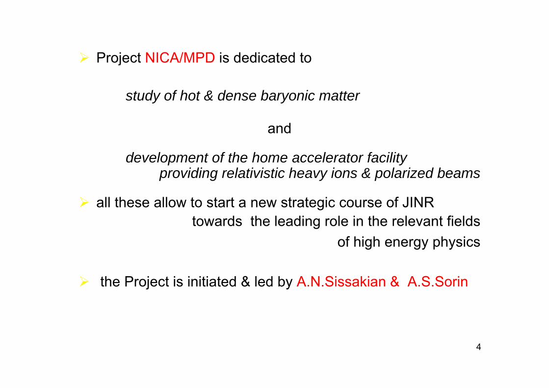
Physics tasks for Spin Physics Detector
MMT DY processes with L&T polarized p & D beams:
Physics tasks for Spin Physics Detector
- MMT-DY processes with L&T polarized p & D beams:- extraction of unknown (poor known) PDF- PDFs from J/y production processes
- Spin effects in baryon, meson & photon productions
- Spin effects in various exclusive reactions & diffractive processes
- Cross sections, helicity amplitudes & double spin asymmetries (Krisch effect) in elastic reactions( sc e ect) e ast c eact o s
- Spectroscopy of quarkoniums
- Polarimetry
7

NICA/MPD –competitive & complimentary toNICA/MPD competitive & complimentary to
i i t- running experiments:- STAR, Phenix at RHIC- NA49/NA61 at CERN- HADES at GSI
- in preparation:p p- ALICE at CERN- CBM at GSI
NICA / MPD advantages- optimal energy range for max baryonic density close to 4 pi geometry- homogeneous acceptance & resolution functions versus measured & scanned parameters (kinematics, b, energy etc.)
8
p ( , , gy )

The NICA Project goals formulated in NICA CDR are the following:
1a) Heavy ion colliding beams 197Au79+ x 197Au79+ at √sNN = 4 ÷ 11 GeV (1 ÷ 4.5 GeV/u ion kinetic energy )
at Laverage= 1⋅1027 cm-2⋅s-1 (at √sNN = 9 GeV)
1b) Light-Heavy ion colliding beams of the same energy range and luminosity
2) Polarized beams of protons and deuterons:p↑p↑ √sNN = 12 ÷ 25 GeV (5 ÷ 12.6 GeV kinetic energy )
d↑d↑ √sNN = 4 ÷ 13.8 GeV (2 ÷ 5.9 GeV/u ion kinetic energy )
9

Colliders & Synchrotrons: Luminosity vs Energy (√s)
Relativistic Nuclear Physics
1000
Colliders & Synchrotrons: Luminosity vs Energy (√s)
Synchrotrons:SIS100
SIS300
1
10
1001e32L(E)
1 30
SIS100
SPS
0,01
0,1
11e30
1e28
U-10
Nuclotron U-70
0,0001
0,001
1e26 LHC (Pb82+)RHIC (Au79+)
NICA
0,000001
0,00001
0,1 1 10 100 1000 100000.1 1.0 GeV 10 100 1.0 TeV 10 1e24
RHIC (Au )
√sη ρω φ J/Ψ Υ W±Z0 t
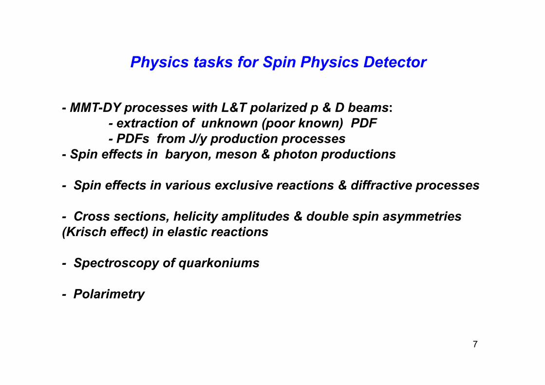
Rezults of the 41th run at Nuclotron (March, 2010)
Generated and accelerated ions of :С (А 12 Z 4)С (А=12, Z=4)Хе (А=124, Z=42) QuickTime™ and a
decompressorare needed to see this picture.
Image of the Хе beam (Е 0 6 GeV/n)Image of the Хе beam (Е = 0,6 GeV/n)On the photoplate (extraction flange)
Хе beam (124, 42+) was accelerated up to 570 MeV/n and 1 GeV/n and succesfulyand 1 GeV/n, and succesfuly extracted.

NICA statusNICA status(leader Igor Meshkov)(leader Igor Meshkov) MPD
ColliderC = 400 m
2.3 m
4.0 m
Booster
Ion source &
KRION-6T & HILac
Nuclotron beam transfer line
Nuclotron beam lines & fixed target
experiments
Ion source & “Old” linac
experiments(to be optimized)
Spin Physics Detector (SPD)Synchrophasotron
Nuclotron
Detector (SPD)yokeBeam transfer lines & New research area
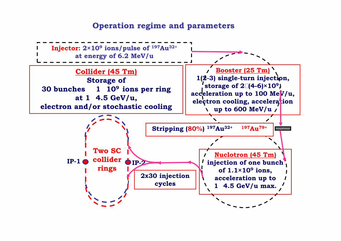
Operation regime and parameters
Injector: 2×10⁹ ions/pulse of 197Au32+
at energy of 6.2 MeV/u
Collider (45 Tm)Storage of
30 bunches � 1�109 ions per ring
Booster (25 Tm)1(2-3) single-turn injection,
storage of 2 (4-6)×109,acceleration up to 100 MeV/uat 1�4.5 GeV/u,
electron and/or stochastic cooling
acceleration up to 100 MeV/u,electron cooling, acceleration
up to 600 MeV/u
Stripping (80%) 197Au32+ � 197Au79+
Nuclotron (45 Tm)injection of one bunch
of 1.1×10⁹ ions,IP-1 IP-2
Two SCcollider rings
2х30 injection acceleration up to 1�4.5 GeV/u max.
2х30 injection cycles

St in P c ssOperation regime and parameters
64 injection cycles to Collider ringsof 1⋅109 ions 197Au79+ per cycle
1 7⋅1010 ions/ring Storing Process
2 Booster magnetic field
nits
electron
1.7 10 ions/ring
0 5
11,5
t), a
rb. u
nelectroncooling Extraction,
stripping to 197Au79+
00,5
0 2 4 6B
(tt, [s] 1 (2-3) injection cycles,
electron cooling (?)
1,5
2
ts
Nuclotron magnetic fieldelectron cooling (?)
bunch compression
0,5
1
,5
, arb
. uni
t bunch compression,extraction
injection
0
,
0 2 4 6
B(t)
,
t, [s]
j

Collider (2T) Conceptual Design ⇒ in progress
Ring circumference m 450Ring circumference, m 450Number of interaction points (IP) 2Bρ max, T⋅m 45.0Ion kinetic energy (197Au79+), GeV/u 1.0 ÷ 4.50gy ( ),Dipole field (max), T 2Quad gradient (max), T/m 30Long straight sections: number / length, m 2 / 82Short straight sections: number / length, m 2 / 25Free space at IP (for MPD detector) m 9Free space at IP (for MPD detector), m 9Beam crossing angle at IP 0Number of dipoles (arc)/ length, m 48 / 1.5Number of quads (arc)/ length, m 24 / 0.6βx_max / βy_max in arc, m 16 / 16Dx_max / Dy_max in arc, m 3.0 / 0.1βx_min / βy_min in IP, m 0.35 / 0.35D / D i IP1 0 0 / 0 0Dx / Dy in IP1, m 0.0 / 0.0Betatron tunes Qx / Qy 6.6 / 7.6Chromaticity Q′x / Q′y -23 / -26Transition energy γ tr 4 89
15
Transition energy, γ_tr 4.89Vacuum, pTorr 100 ÷ 10at 3.5 AGeV -> L= 10^27
at 1.0 AGeV -> L = 5*10^25
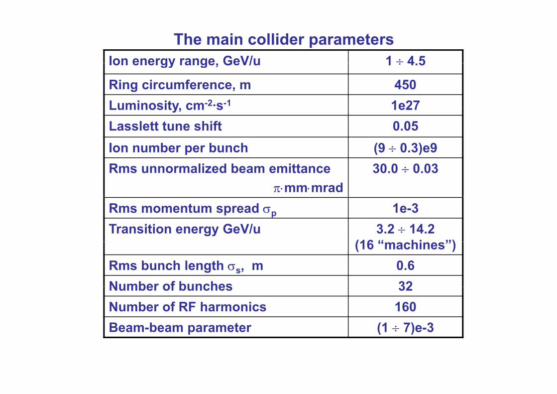
The main collider parametersIon energy range GeV/u 1 ÷ 4 5Ion energy range, GeV/u 1 ÷ 4.5
Ring circumference, m 450Luminosity cm-2·s-1 1e27Luminosity, cm s 1e27Lasslett tune shift 0.05Ion number per bunch (9 ÷ 0.3)e9o u be pe bu c (9 0.3)e9Rms unnormalized beam emittance
π⋅mm⋅mrad30.0 ÷ 0.03
Rms momentum spread σp 1e-3Transition energy GeV/u 3.2 ÷ 14.2
(16 “ hi ”)(16 “machines”)Rms bunch length σs, m 0.6Number of bunches 32Number of bunches 32Number of RF harmonics 160Beam-beam parameter (1 ÷ 7)e-3Beam beam parameter (1 ÷ 7)e 3

Main requirements to NICA ring design.
• Ring circumference ~ 400 m
• Racetrack shape of the ring with fixed distance between IP points.
• Stochastic cooling (Palmer method): Stochastic cooling (Palmer method): Longitudinal + Horizontal needs (2n + 1)π – betatron phase advance between PickUp (located at βmax, Dmax) and Kicker (longitudinal – located at Dmax)Vertical needs (2n + 1/2) π – betatron phase advance between PickUp andVertical needs (2n 1/2) π betatron phase advance between PickUp and Kicker
• Electron cooler – at straight section – needs ~9 m length with (D=0, βx z ~ 10m g g ( , βx,z– adjustable)
• 4.5 – 1 GeV/n – experiment kinetic energy (for Au) & possibility of the acceleration of the proton beam & slip factor requirements => variation of γtr !
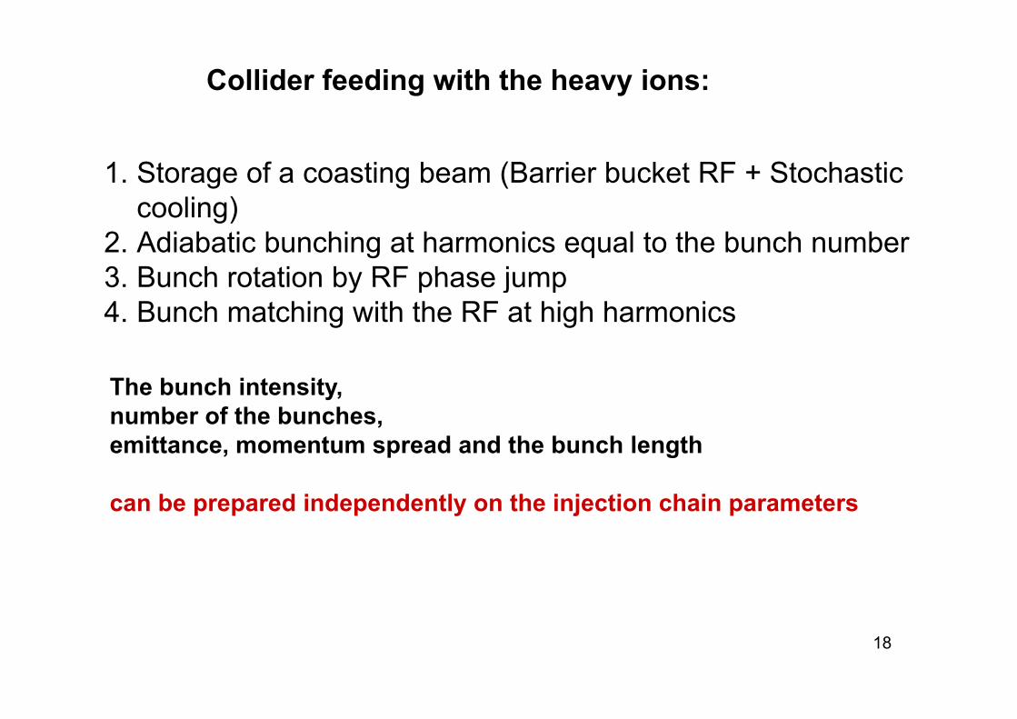
Collider feeding with the heavy ions:
1. Storage of a coasting beam (Barrier bucket RF + Stochastic )cooling)
2. Adiabatic bunching at harmonics equal to the bunch number3 Bunch rotation by RF phase jump3. Bunch rotation by RF phase jump4. Bunch matching with the RF at high harmonics
The bunch intensity, number of the bunches, emittance momentum spread and the bunch lengthemittance, momentum spread and the bunch length
can be prepared independently on the injection chain parameters
18
h h ( )
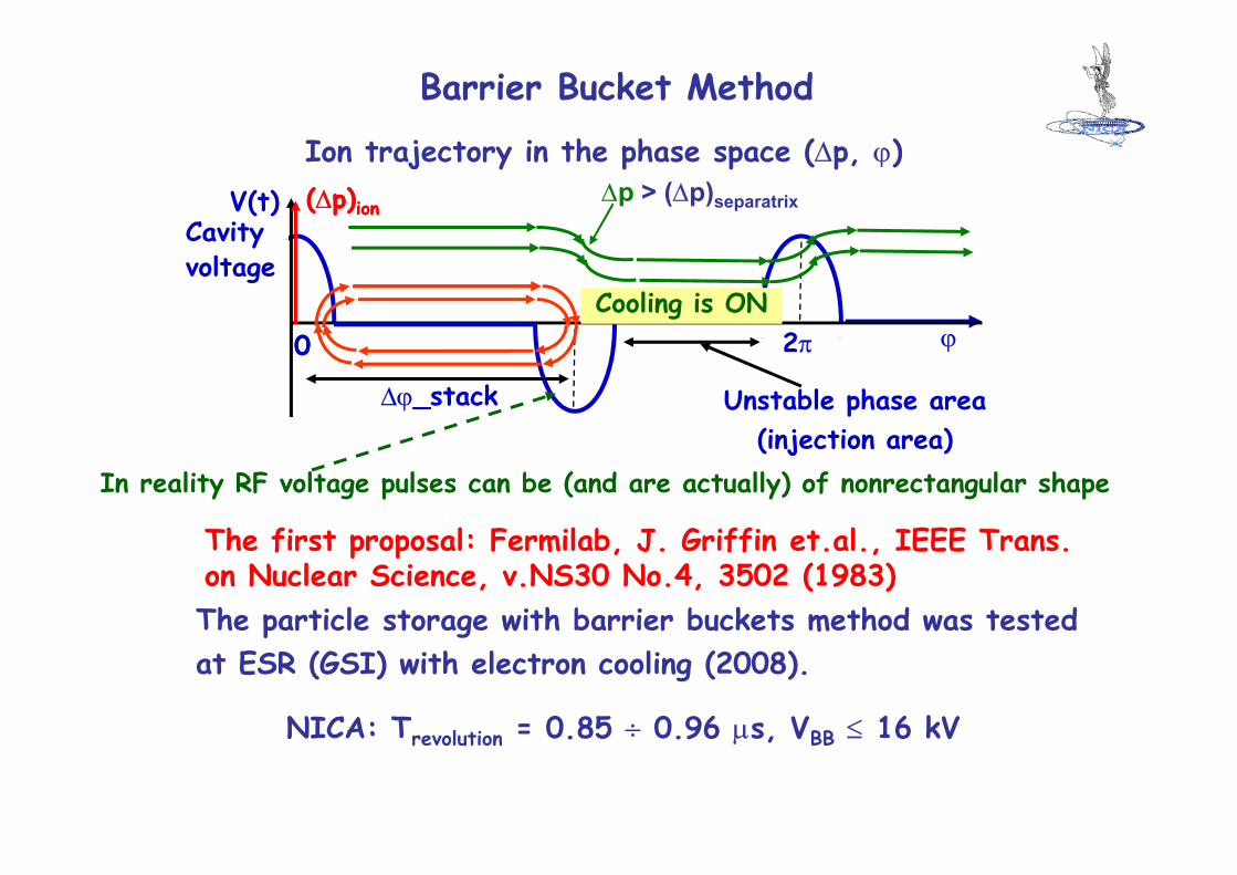
Barrier Bucket Method
Ion trajectory in the phase space (∆p, ϕ)V(t)
Cavity(∆p)ion(∆p)ion ∆p > (∆p)separatrix
2
Cavityvoltage
ϕ00Cooling is ON
2π ϕ00
Unstable phase area (injection area)
∆ϕ_stack(injection area)
In reality RF voltage pulses can be (and are actually) of nonrectangular shape
The first proposal: Fermilab J Griffin et al IEEE Trans
The particle storage with barrier buckets method was tested
The first proposal: Fermilab, J. Griffin et.al., IEEE Trans.on Nuclear Science, v.NS30 No.4, 3502 (1983)
NICA: Trevolution = 0.85 ÷ 0.96 µs VBB ≤ 16 kV
p gat ESR (GSI) with electron cooling (2008).
NICA: Trevolution 0.85 ÷ 0.96 µs, VBB ≤ 16 kV

Stochastic cooling Electron coolingUseful for stacking Ineffective at E < 2 GeV/u
Effective at whole energy range;Ineffective for stacking, Problems due to recombination
Collisions
Long bunch ~ 1.5 - 2 m Short bunch 0.3 – 0.6 m
Low VRF ~ 20-30 kV Large VRF ~ 100 kV
The luminosity is limited by Luminosity is limited by bunchIBS stability∆Q < 0.02, Ipeak < 2 A, ξ < 0.005 ∆Q ~ 0.05, Ipeak ~ 5-10 A
T l i i i IT β* 0 5 i blTo concentrate luminosity in IT β* ~ 0.2–0.3 m
β* ~ 0.5 m is acceptable
η < 0.03 Does not sensitive to ηη 0.03 Does not sensitive to η(choice of η is determined by RFsystem)
R i IBS i i i C li i l h20
Requires IBS optimization Cooling power is large enough to suppress IBS
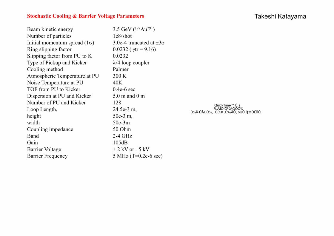
Stochastic Cooling & Barrier Voltage Parameters
Beam kinetic energy 3.5 GeV (197Au79+)Number of particles 1e8/shot
Takeshi Katayama
Number of particles 1e8/shotInitial momentum spread (1σ) 3.0e-4 truncated at ±3σRing slipping factor 0.0232 ( γtr = 9.16)Slipping factor from PU to K 0.0232Type of Pickup and Kicker λ/4 loop coupleryp p p pCooling method PalmerAtmospheric Temperature at PU 300 KNoise Temperature at PU 40KTOF from PU to Kicker 0.4e-6 sec
QuickTime™ Ë a ‰ÂÍÓÏÔ¾ÂÒÒÓ¾
ھ·ÛÂÚÒ½, ˜ÚÓ·Þ ‚ˉÂÚ¸ ðÚÛ Í‡¾ÚËÌÍÛ.
Dispersion at PU and Kicker 5.0 m and 0 mNumber of PU and Kicker 128Loop Length, 24.5e-3 m, height 50e-3 m,g ,width 50e-3mCoupling impedance 50 OhmBand 2-4 GHzGain 105dBBarrier Voltage ± 2 kV or ±5 kVBarrier Frequency 5 MHz (T=0.2e-6 sec)

Collider luminosity vs Ion EnergyT t t t ∆Q C tTwo outmost cases at ∆QLasslett = Const :
1) L(E) = Const ⇒ ;53norm32ion1,1)E(Nγβ
εγβ
∝∝
2) Nion(E) = Const ⇒ .322norm )E(L,1 γβ
βγε ∝∝
101.6
N1 E( )
1.6
1.4 N_ion/bunch vs Energy
[1E9]
βγ2
L1 E( )
10
1.0
L(E) [1E27 cm-2·s-1]
ε_norm(E) [π·mm·mrad]
10N1 E( )
N2 E( )1.2
1.0
L1 E( )
L2 E( )
0.1
ε1_norm E( )
ε2_norm E( )1.0 0.8
4.50.5 E0.8
0.5 1.5 2.5 3.5 4.5 E, GeV/u
0.01
4.50.5 E0.01
0.5 1.5 2.5 3.5 4.5 E, GeV/u
E0.1
0.5 1.5 2.5 3.5 4.5 E GeV/uE, GeV/u

Collider: electron cloud effect
Electron cloud formation criteria
The necessary condition: ,lZb)N(
22
necessarybunch ⋅≥ βy
The sufficient condition (“multipactor effect”):lZr spacee
necessarybunch β
b iεβ
Here βc is ion velocity, Z – ion charge number, b – vacuum chamber radius,
.cm2Zr
b)N( 2e
crit
esufficientbunch
εβ⋅≥
re – electron classic radius, lspace – distance between bunches, me – electron mass, c – the speed of light,ε ~ 1 keV electron energy sufficient for secondary electron generation
For NICA bunch parameters (109 197Au79+ ions/bunch)
εcrit ~ 1 keV – electron energy sufficient for secondary electron generation.
p ( )
(Nbunch)necessary ~ 7⋅108, (Nbunch)sufficient ~ 6⋅109.

Collider lattice related problems to be solved
Ring structure optimization on higher IBS time,An attempt of combination of “Flexible lattice” (transition energy change with energy) with “IBS requirement”energy change with energy) with IBS requirement ,Insertion devices in structure (Ecool, Spin rotators, MPD). Coupling compensation,Optimization of correction systems (orbit, chromaticity, resonances),DA l l ti i li fi ld ( t h ti it DA calculation in non-linear fields (magnets, chromaticity correctors),……
24

Beam stability
Chosen beam parameters for NICA at 3.5 GeV/u and Nb = 109 b h l th 0 3 t b li bl ith i f109, bunch length 0.3 m seems to be realizable with using of the following cures:
• Suppression of high order modes (HOM) in accelerating cavities.
• Design of good chamber with small coupling impedances
• Use of the chromaticity correction circuit for suppression of high order head tail modes (or octupole families to increasehigh order head tail modes (or octupole families to increase non-linear Landau damping).

The problem of the slippage factor and RF voltage is discussed in the Collider CDR, wherewe have found rather strict requirements to ringlattice tuning:
40 kV ≤ V (E ) ≤ 140 kV40 kV ≤ VRF(EA) ≤ 140 kVat σs = 0.6 m, σp = 1e-3
Several different values of γcrit

NICA project status and plans
Since publication of the 1-st version of the NICA CDRpThe Concept was developed, the volumes I,II and III of the TDR have been completed:
Volume I – Part 1, General description- Part 2, Injector complexPart 2, Injector complex
Volume II – Part 3, Booster-Synchrotron- Part 4 Nuclotron - NICA- Part 4, Nuclotron - NICA
Volume III – Part 5, ColliderV l IV P t 6 B di ti & t lVolume IV - Part 6, Beam diagnostics & control
- Part 7, Cryogenic system- Part 8, Radiation safety & control system
Volume V – Part 9, Civil Engineering
27

Q-
nC 22 20 18
Q- = aB3
18 16 14 12
f(B) = C⋅B3
Nion ∝ B3
12 10 8
(Nion)eTotal numberOf electrons/ions inthe electron strings
6
4 2
0
xp
(Ne)exp
(nC) vs appliedmagnetic field [T]
0.0 1.0 2.0 3.0 4.0 5.0 6.0 7.0 T, B
0
Source B [T] Ions Nion/pulseKRION-2 3.0 Au30+ 5⋅108 exp
2010:- run at Nuclotron;
KRION 2 3.0 Au 5 10 expKRION-6Т 6.0 Au32+ 2⋅109 scaled B2- KRION-6Тs commissioning
is planned for end of 2010
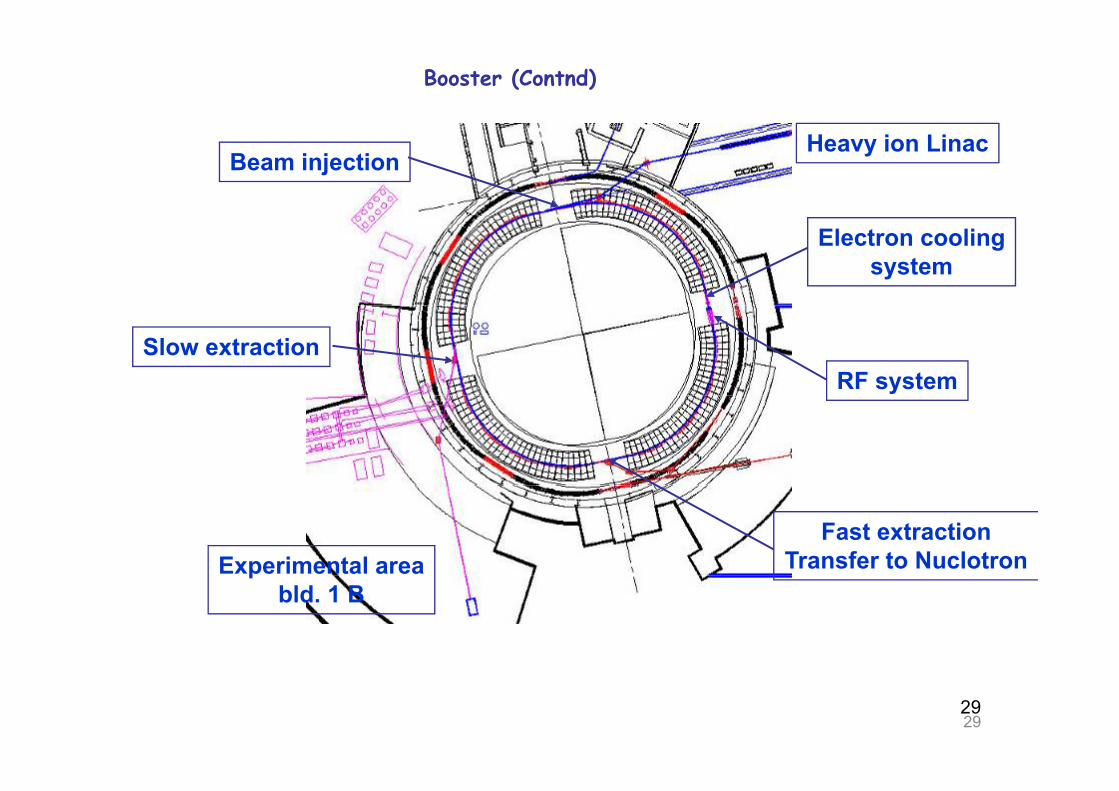
Booster (Contnd)
Heavy ion LinacBeam injection
2.3 m
Electron coolingsystem
4.0 mSlow extractionRF system
Experimental areaFast extraction
Transfer to Nuclotronpbld. 1 B
2929

Booster FODO latticeBooster FODO lattice
Working point ~ 5.8 / 5.85
Chromaticity -6.5
∆p/p (max/min) 1E–3 / 8E–4p p ( )
Norm. emittance 1 π·mm·mrad
Booster superperiod lattice functionsBooster superperiod lattice functionsBeta function (max) 14.5 m
3030

Magnetic system design ⇒ in progress
Name of the parameter Unit Dipole QuadrupoleNumber of magnets 64 + 1 32 + 2 Maximum magnetic induction (field T (T/m) 2.0 23Maximum magnetic induction (fieldgradient)
T (T/m) 2.0 23
Effective magnetic length m 2.2 0.52Ramp rate dB/dt T/s ≤ 0.5 -Field quality ∆ B/ B (∆ G/ G ) at R=30mm ± 6⋅10-4q y / ( G/ G )Useable aperture mm 70 70Pole radius m - 0.036Bending angle deg 5 5/8 -
Radius of curvature m 22.5 -Yoke width m 0.204 0.22Yoke height m 0. 504 0.52Distance between the beams mm 320Overall weight kg 1200 230g gCurrent at maximum field kA 12 12Number of turns in the winding 10 4 Inductance µH 370 22Stored energy kJ 26.6 1.58Vacuum shell outer diameter mm 700Heat releases W 10 4.8SC cable cooling channel diameter mm 3.0 3.0Cable length in the two windings m 110 14
• Construction of the dipole magnet prototype is scheduled for 2010.
31
Pressure difference between the helium headers kPa 27Maximal temperature of helium K 4.65
• Design of the regular collider twin bore quadrupole lens with hyperbolic poles is in progress.
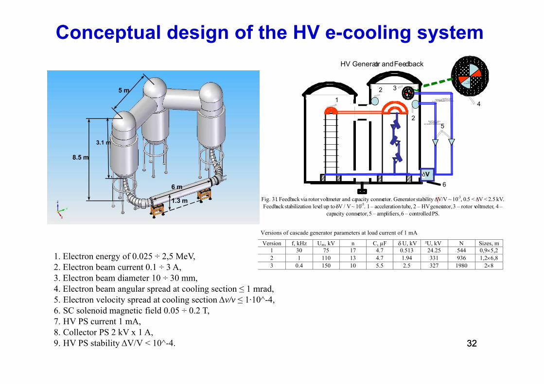
Conceptual design of the HV e-cooling systemHV G dF db k
5 m
HV Generator andFeedback
2
4
3
1 QuickTime™ and a decompressor
are needed to see this picture.
QuickTime™ and a decompressor
are needed to see this picture.
QuickTime™ and a decompressor
are needed to see this picture.
QuickTime™ and a decompressor
are needed to see this picture.
QuickTime™ and a decompressor
are needed to see this picture.
QuickTime™ and a decompressor
are needed to see this picture.QuickTime™ and a decompressor
are needed to see this picture.
3.1 m
4
52
QuickTime™ and a decompressor
are needed to see this picture.
8.5 m
6 m
V 6
1.3 m Fig. 31. Feedback via rotor voltmeter and capacity connector. Generator stability V/V ~ 10-3, 0.5 < V < 2.5 kV. Feedback stabilization level up to V / V ~ 10-5. 1 – acceleration tube, 2 – HV generator, 3 – rotor voltmeter, 4 –
capacity connector,5 – amplifiers,6 – controlledPS.
Versions of cascade generator parameters at load current of 1 mA
1. Electron energy of 0.025 ÷ 2,5 MeV,2. Electron beam current 0.1 ÷ 3 A,3 Electron beam diameter 10 ÷ 30 mm
g p
Version f, kHz Um, kV n C, µF U, kV ²U, kV N Sizes, m 1 30 75 17 4.7 0.513 24.25 544 0,9×5,2 2 1 110 13 4.7 1.94 331 936 1,2×6,8 3 0.4 150 10 5.5 2.5 327 1980 2×8
3. Electron beam diameter 10 ÷ 30 mm,4. Electron beam angular spread at cooling section ≤ 1 mrad,5. Electron velocity spread at cooling section ∆v/v ≤ 1·10^-4,6. SC solenoid magnetic field 0.05 ÷ 0.2 T,7 HV PS current 1 mA
3232
7. HV PS current 1 mA,8. Collector PS 2 kV x 1 A,9. HV PS stability ∆V/V < 10^-4.

Stochastic cooling system prototype at Nuclotron for HESR/NICAB
η= 0.032E = 3.5 AGeVParticles (d C) 1e9
BParticles (d, C) = 1e9Momentum spread = 1.0e-3TOF PU-KK = 0.42*1.0e-6Revolution f = 1.2e-6
Creation of test-bench for pick-up measurements (warm/cold);measurements (warm/cold);
Using of COSY equipment in Nuclotron cryostaty
Slot-coupler structure
2 ÷ 4 GHz (~10 sec)
33

Civil engineeringState Specialized Design Institute (Moscow):
34
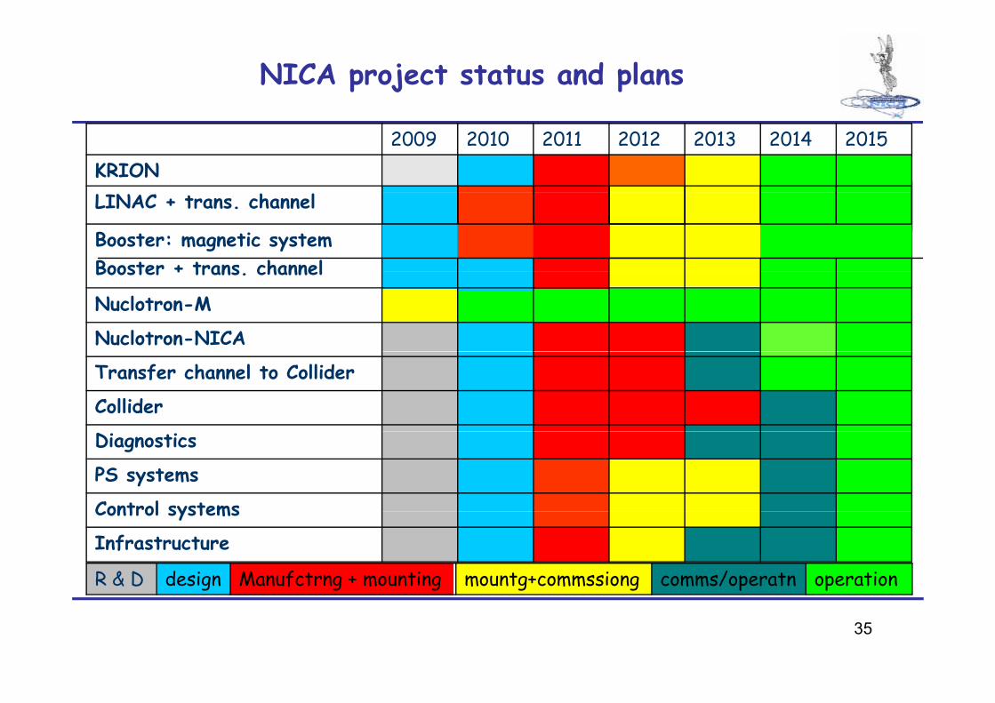
NICA project status and plans
KRION2015201420132012201120102009
Booster + trans channel
LINAC + trans. channel
Booster: magnetic system
Nuclotron-NICA
Nuclotron-M
Booster + trans. channel
Collider
Transfer channel to Collider
Control systems
PS systems
Diagnostics
Infrastructure
Control systems
operationcomms/operatnmountg+commssiong Manufctrng + mountingdesignR & D
35
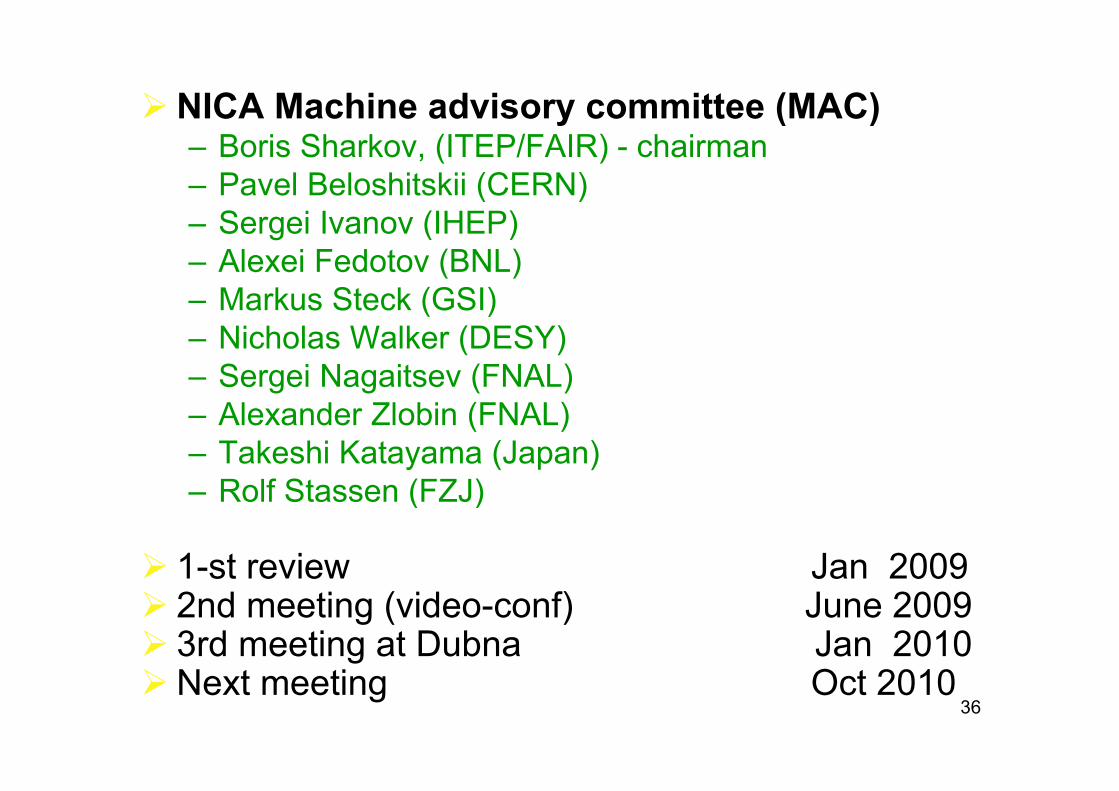
NICA Machine advisory committee (MAC)– Boris Sharkov, (ITEP/FAIR) - chairman– Pavel Beloshitskii (CERN)
S i I (IHEP)– Sergei Ivanov (IHEP)– Alexei Fedotov (BNL) – Markus Steck (GSI)Markus Steck (GSI)– Nicholas Walker (DESY)– Sergei Nagaitsev (FNAL)– Alexander Zlobin (FNAL)– Takeshi Katayama (Japan)
Rolf Stassen (FZJ)– Rolf Stassen (FZJ)
1-st review Jan 20091 st review Jan 20092nd meeting (video-conf) June 20093rd meeting at Dubna Jan 2010
36Next meeting Oct 2010
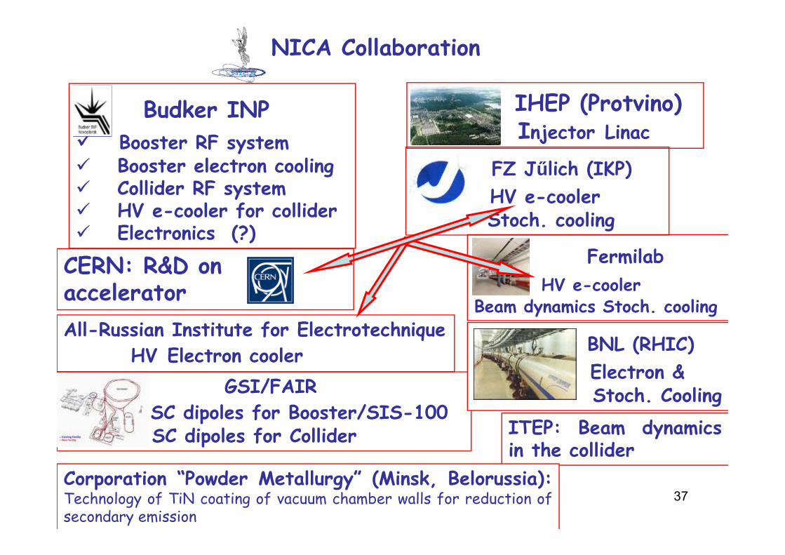
NICA Collaboration
Budker INPBooster RF system
IHEP (Protvino)Injector Linacy
Booster electron coolingCollider RF systemHV e-cooler for collider
FZ Jűlich (IKP)HV e-coolerSt h li HV e cooler for collider
Electronics (?)Stoch. cooling
Fermilab l
CERN: R&D onHV e-cooler
Beam dynamics Stoch. coolingAll-Russian Institute for Electrotechnique
BNL (RHIC)
accelerator
GSI/FAIR
qHV Electron cooler BNL (RHIC)
Electron &Stoch. Cooling
SC dipoles for Booster/SIS-100SC dipoles for Collider
gITEP: Beam dynamicsin the collider
37Corporation “Powder Metallurgy” (Minsk, Belorussia):Technology of TiN coating of vacuum chamber walls for reduction ofsecondary emission

Thank you for your attention!
38