Embed Size (px)
Citation preview
1
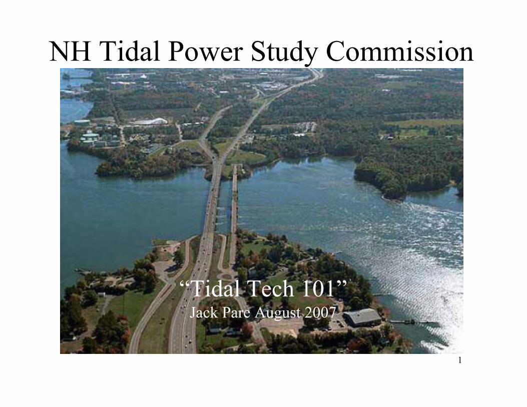
NH Tidal Power Study Commission
“Tidal Tech 101”Jack Pare August 2007
2
NH Electricity Prices/Costs
• In 2005, NH had the 3rd highest electricity prices
in the US, behind Hawaii and New York.
• In 2006, NH prices held steady, while other rose.
NH is now 6th - behind Hawaii, Connecticut,
Massachusetts, New York and Rhode Island.
• Cost of energy generation sources (e.g. coal, oil,
gas) is a major contributor
– all must be imported
from US Dept of Energy - Electric Power Monthly January 12, 2007
http://www.eia.doe.gov/cneaf/electricity/epm/table5_6_a.html
State-by-state rank values computed from data
3
NH Electricity Prices/Costs
National average cost of Electricity 8.83 cents per kilowatt hour
NH average cost of Electricity 13.53 cents per kilowatt hour
from US Dept of Energy - Electric Power Monthly January 12, 2007
www.eia.doe.gov/cneaf/electricity/epm/table5_6_a.html
• These electric rates permit Tidal Power to be cost competitive in NH – even before Renewable Energy Certificates are applied.
4
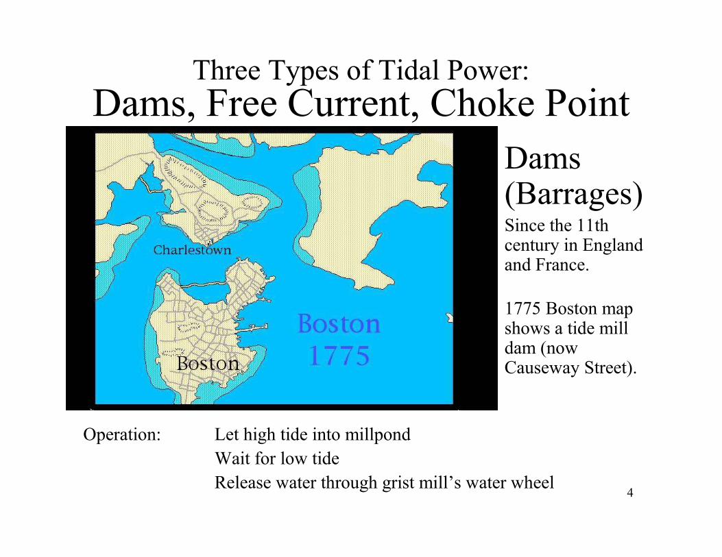
Three Types of Tidal Power:
Dams, Free Current, Choke Point
• Dams (Barrages)
• Since the 11th century in England and France.
• 1775 Boston map shows a tide mill dam (now Causeway Street).
Operation: Let high tide into millpond
Wait for low tide
Release water through grist mill’s water wheel
5
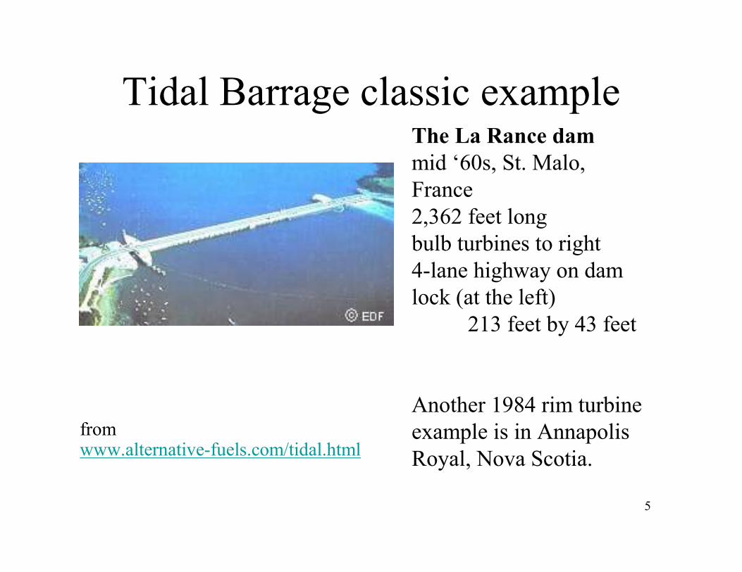
Tidal Barrage classic example
from www.alternative-fuels.com/tidal.html
The La Rance dam
mid ‘60s, St. Malo,
France
2,362 feet long
bulb turbines to right
4-lane highway on dam
lock (at the left)
213 feet by 43 feet
Another 1984 rim turbine
example is in Annapolis
Royal, Nova Scotia.
6
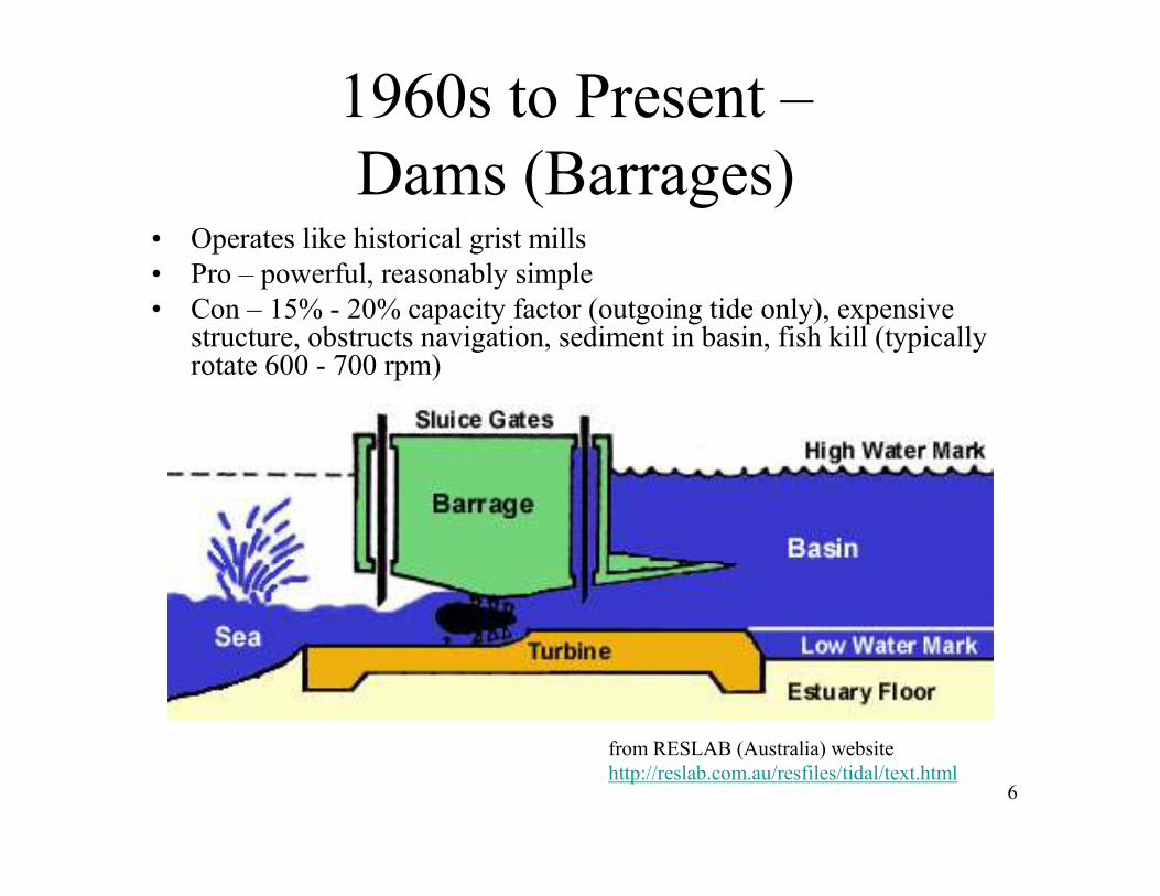
1960s to Present –
Dams (Barrages)• Operates like historical grist mills
• Pro – powerful, reasonably simple
• Con – 15% - 20% capacity factor (outgoing tide only), expensive structure, obstructs navigation, sediment in basin, fish kill (typically rotate 600 - 700 rpm)
from RESLAB (Australia) website
http://reslab.com.au/resfiles/tidal/text.html
7
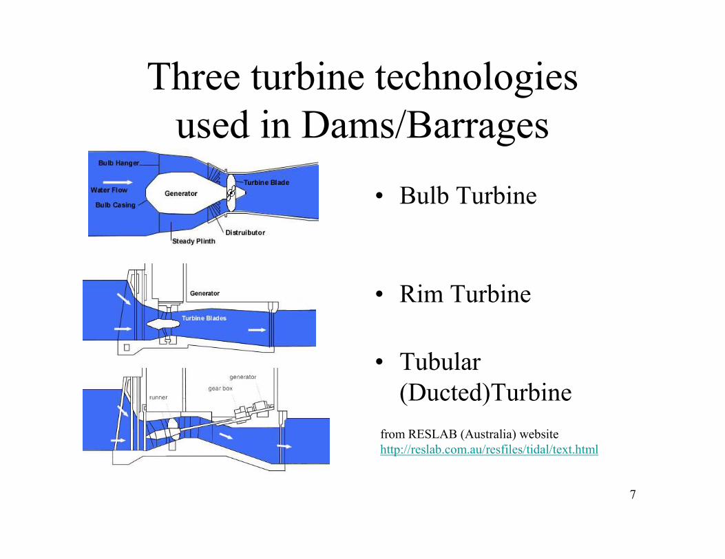
Three turbine technologies
used in Dams/Barrages
• Bulb Turbine
• Rim Turbine
• Tubular
(Ducted)Turbine
from RESLAB (Australia) website
http://reslab.com.au/resfiles/tidal/text.html

8
Ebb Flow Power from Barrage
high
tide
low tide
High tide water retained for falling tide generation
Tide H
eight
Power Output
Max
Time
An 'Ideal' Ebb Flow Power Generator
Time
high
tide
low tide low tide
9
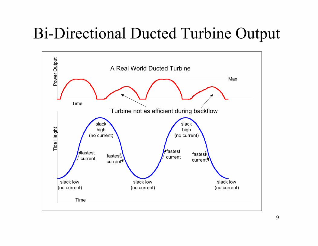
Bi-Directional Ducted Turbine Output
fastest
current
slack
high
(no current)
slack low
(no current)
slack low
(no current)
slack low
(no current)
fastest
current
fastest
currentfastest
current
slack
high
(no current)
Tide Height
Power Output
Max
Time
A Real World Ducted Turbine
Turbine not as efficient during backflow
Time
10
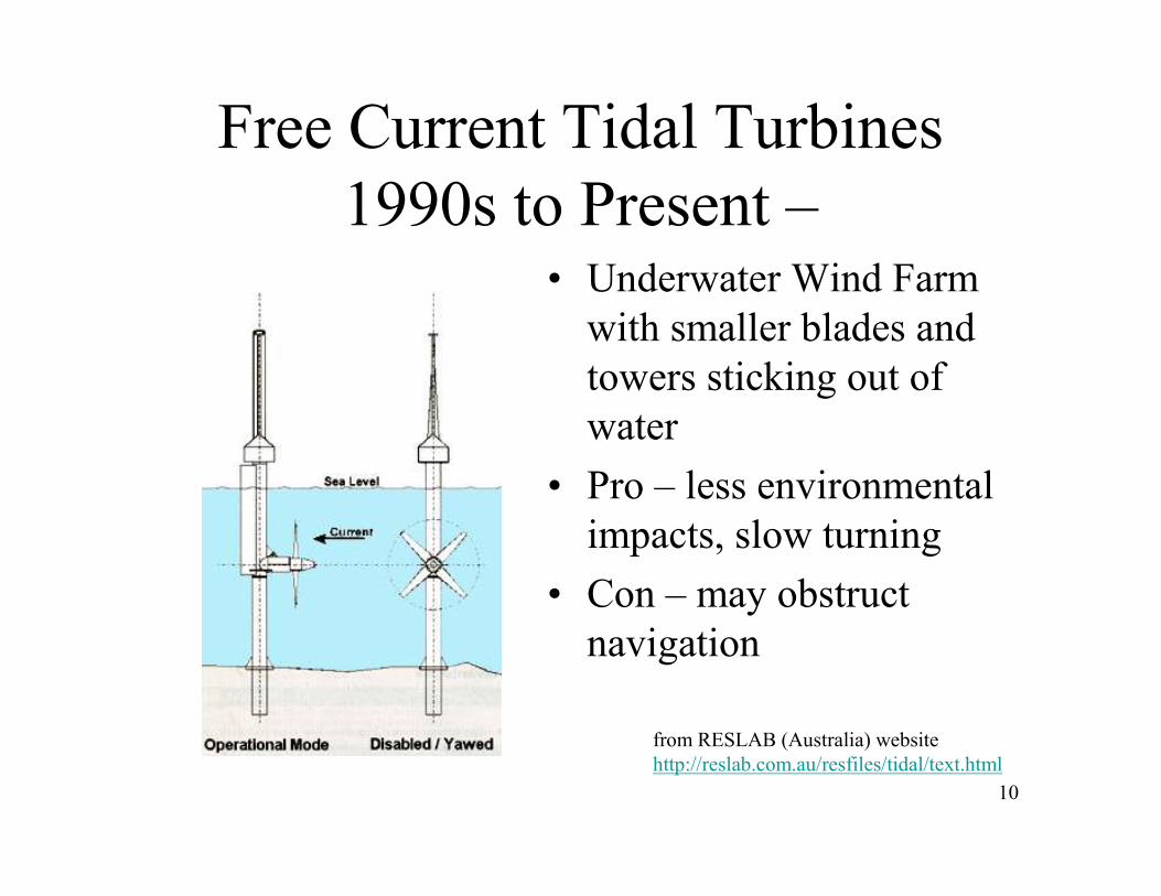
Free Current Tidal Turbines
1990s to Present –• Underwater Wind Farm
with smaller blades and
towers sticking out of
water
• Pro – less environmental
impacts, slow turning
• Con – may obstruct
navigation
from RESLAB (Australia) website
http://reslab.com.au/resfiles/tidal/text.html
11
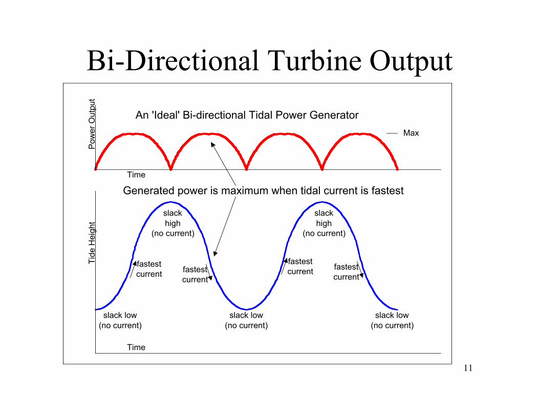
Bi-Directional Turbine Output
fastest
current
slack
high
(no current)
slack low
(no current)
slack low
(no current)
slack low
(no current)
fastest
current
fastest
currentfastest
current
slack
high
(no current)
Generated power is maximum when tidal current is fastest
Tide Height
Power Output
Max
Time
An 'Ideal' Bi-directional Tidal Power Generator
Time
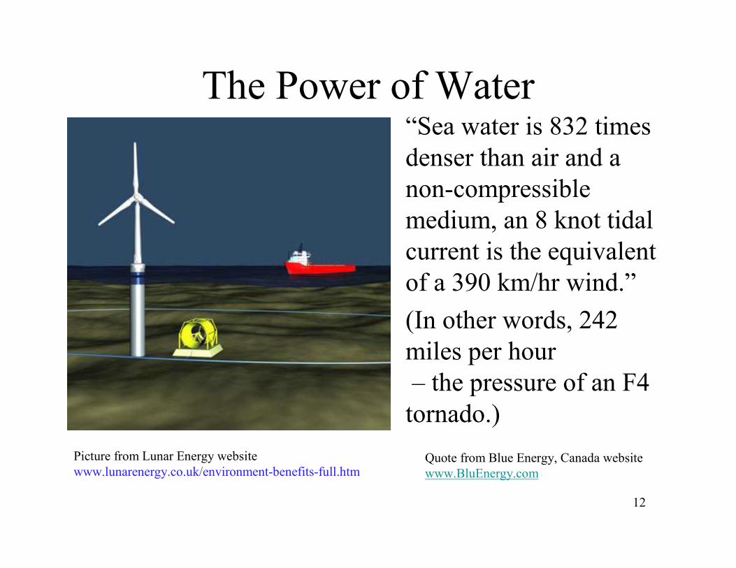
12
The Power of Water• “Sea water is 832 times
denser than air and a
non-compressible
medium, an 8 knot tidal
current is the equivalent
of a 390 km/hr wind.”
• (In other words, 242
miles per hour
– the pressure of an F4
tornado.)
Quote from Blue Energy, Canada website
www.BluEnergy.com
Picture from Lunar Energy website
www.lunarenergy.co.uk/environment-benefits-full.htm
13
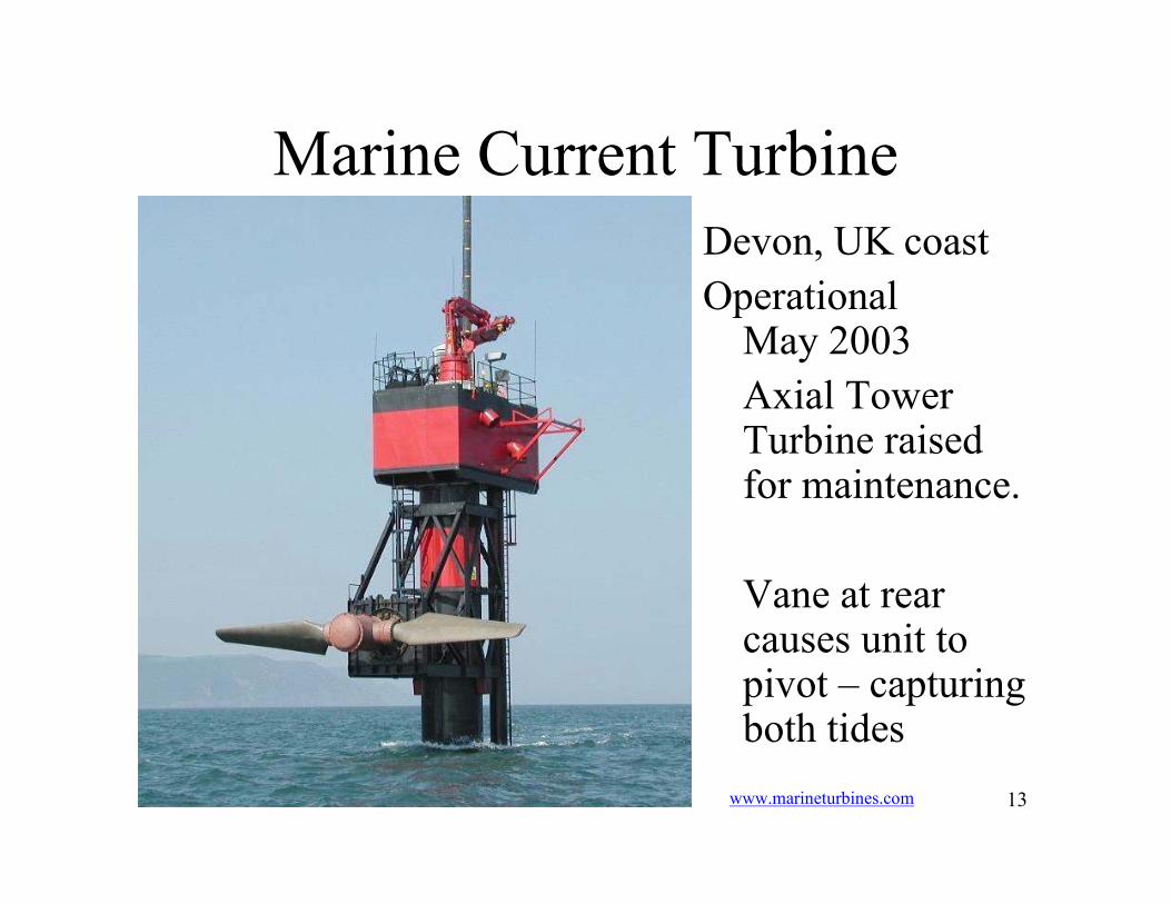
Marine Current Turbine
Devon, UK coast
Operational May 2003
Axial Tower Turbine raised for maintenance.
Vane at rear causes unit to pivot – capturing both tides
www.marineturbines.com
14
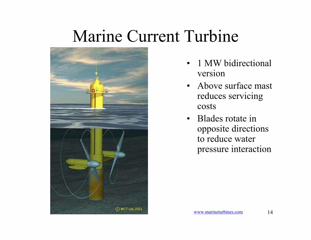
Marine Current Turbine
• 1 MW bidirectional version
• Above surface mast reduces servicing costs
• Blades rotate in opposite directions to reduce water pressure interaction
www.marineturbines.com
15
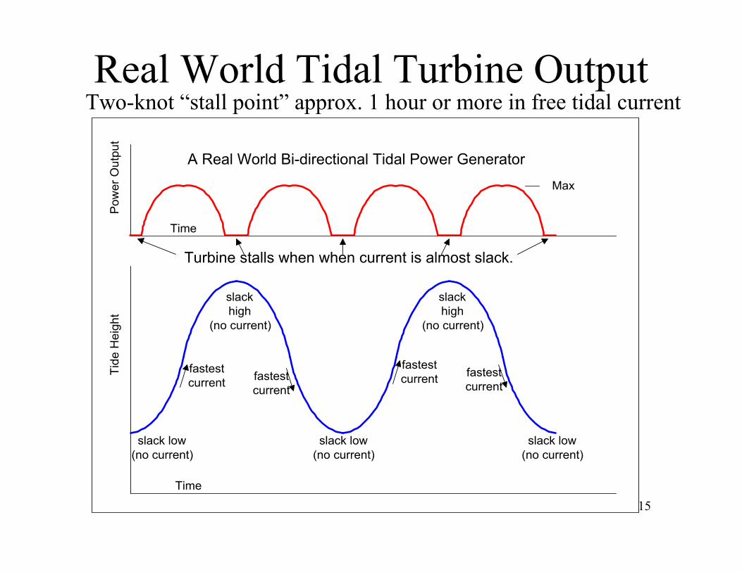
Real World Tidal Turbine OutputTwo-knot “stall point” approx. 1 hour or more in free tidal current
fastest
current
slack
high
(no current)
slack low
(no current)
slack low
(no current)
slack low
(no current)
fastest
current
fastest
currentfastest
current
slack
high
(no current)
Tide H
eight
Power Output
Max
Time
A Real World Bi-directional Tidal Power Generator
Turbine stalls when when current is almost slack.
Time

16
CAPACITY FACTORPower Output
Max
Typical Bi-directional Tidal Power Generator
Time
Capacity Factor defined
Power Output
Max
Typical Hydrocarbon Power Generator
Time
Power Output
MaxMax Power for 100% of Time = 100% Capacity Factor
Time
down for scheduled maintenance
Max Power for 95% of Time = 95% Capacity Factor
varying % Power for varying % of Time = X % Capacity Factor
down for scheduled maintenance

17
TIDAL - FOSSIL FUEL COMBINATIONS
Forecasted D
emand for Power
Power Output
Time
Resulting net power delivered from fossil fuel
Power normally supplied by generator using a fossil fuel
Power supplied by tidal generator
This power curve can be very dependably forecasted
Time
Max
18
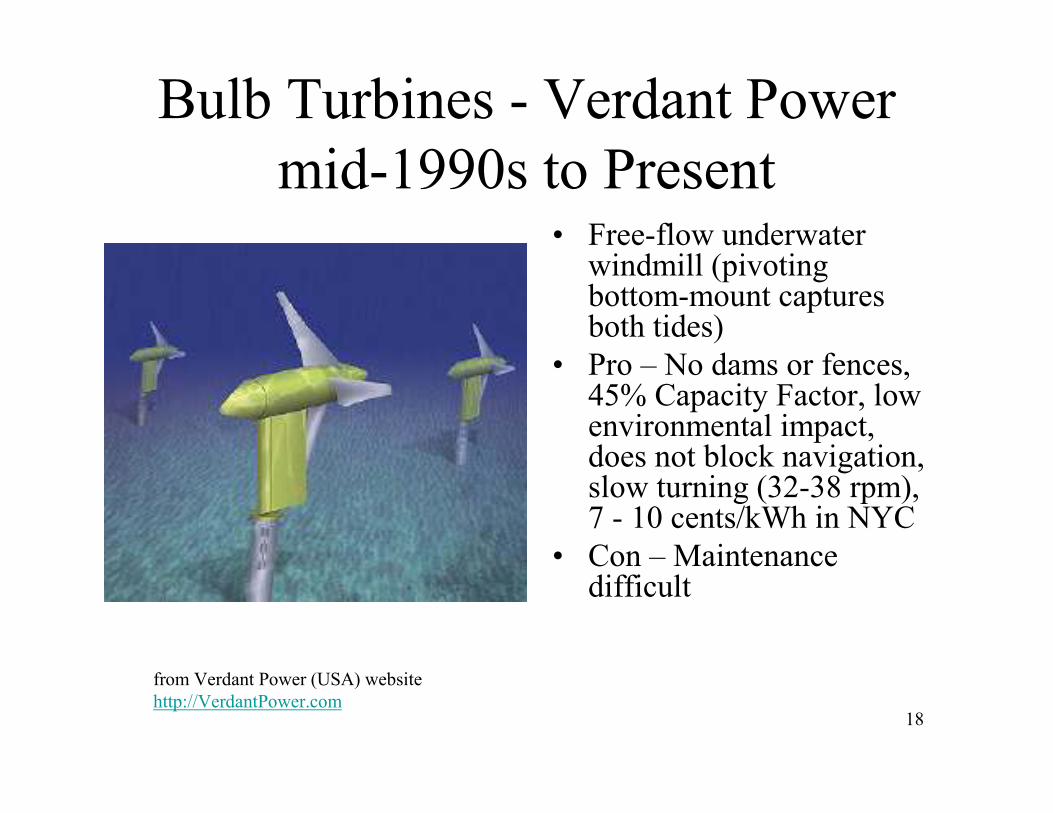
Bulb Turbines - Verdant Power
mid-1990s to Present• Free-flow underwater
windmill (pivoting bottom-mount captures both tides)
• Pro – No dams or fences, 45% Capacity Factor, low environmental impact, does not block navigation, slow turning (32-38 rpm), 7 - 10 cents/kWh in NYC
• Con – Maintenance difficult
from Verdant Power (USA) website
http://VerdantPower.com
19
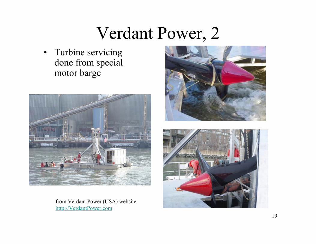
Verdant Power, 2• Turbine servicing
done from special motor barge
from Verdant Power (USA) website
http://VerdantPower.com
20
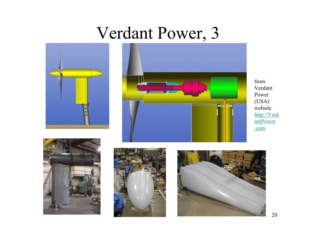
Verdant Power, 3
from
Verdant
Power
(USA)
website
http://Verd
antPower
.com
21
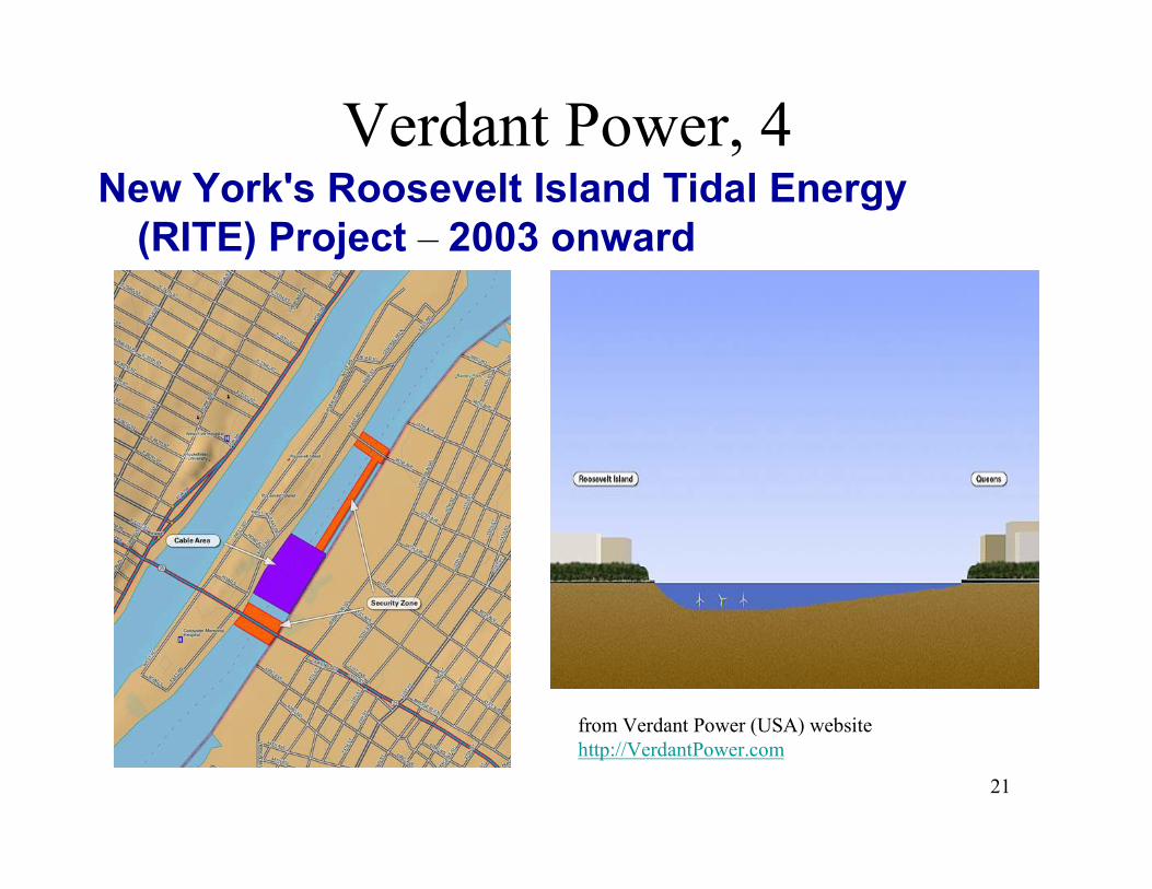
Verdant Power, 4New York's Roosevelt Island Tidal Energy
(RITE) Project – 2003 onward
from Verdant Power (USA) website
http://VerdantPower.com

22
Lunar Energy Ltd, UK
• Venturi-Ducted axial turbine
• Allows 40 degrees off-axis flow
• Ducts reduce interference with nearby turbines
from www.lunarenergy.co.uk
23
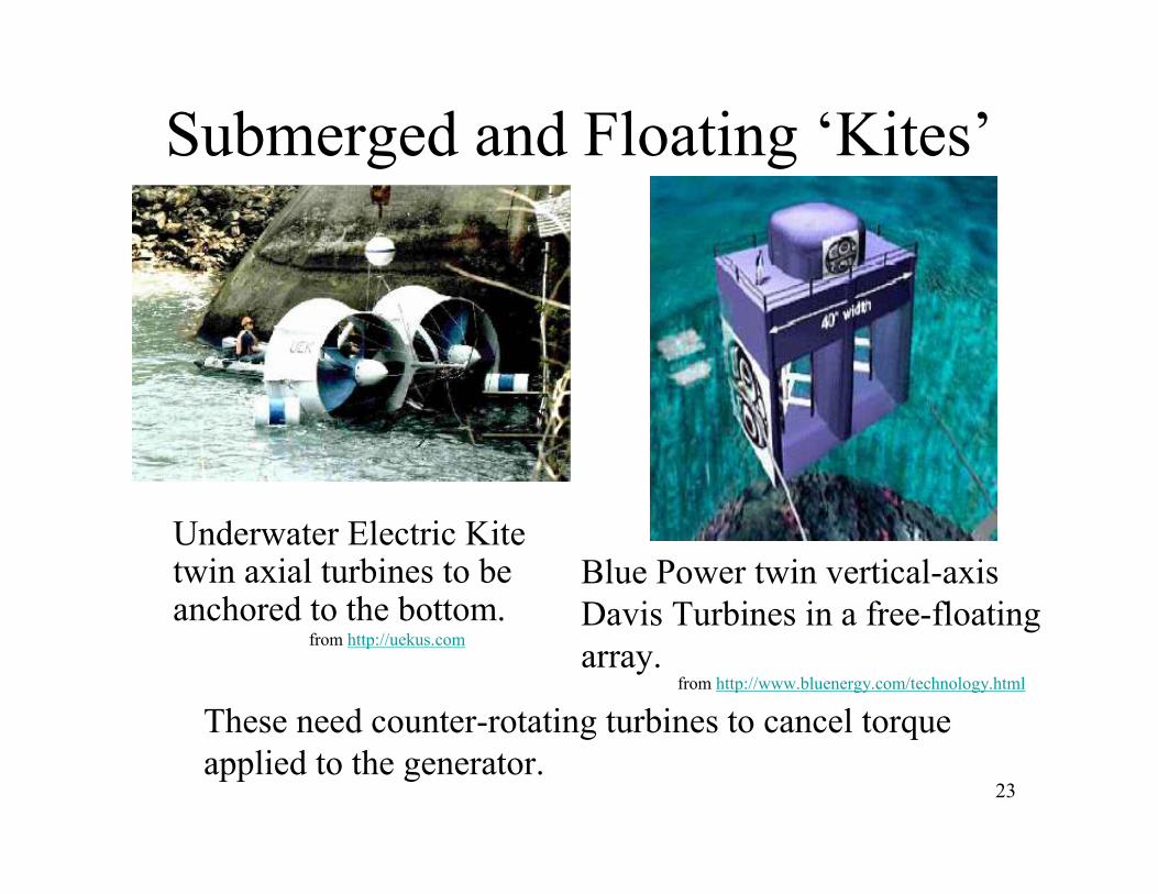
Submerged and Floating ‘Kites’
Underwater Electric Kite twin axial turbines to be anchored to the bottom.
Blue Power twin vertical-axis
Davis Turbines in a free-floating
array.
These need counter-rotating turbines to cancel torque
applied to the generator.
from http://www.bluenergy.com/technology.html
from http://uekus.com
24
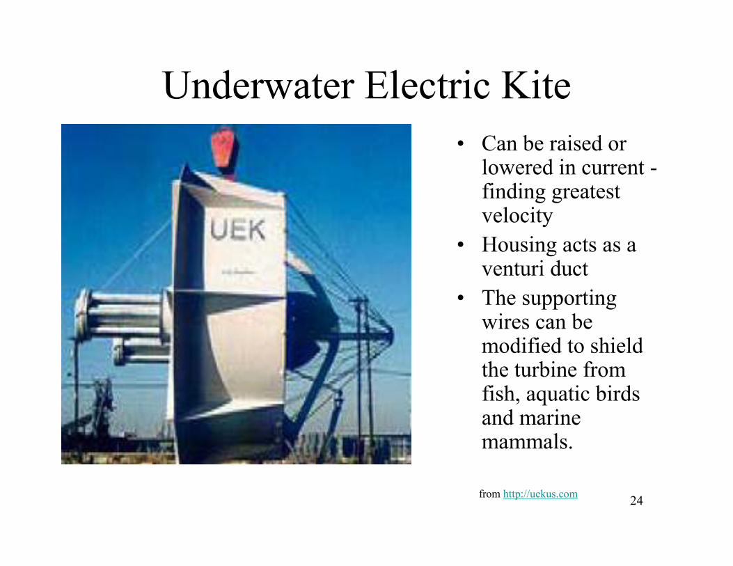
Underwater Electric Kite
• Can be raised or lowered in current -finding greatest velocity
• Housing acts as a venturi duct
• The supporting wires can be modified to shield the turbine from fish, aquatic birds and marine mammals.
from http://uekus.com
25
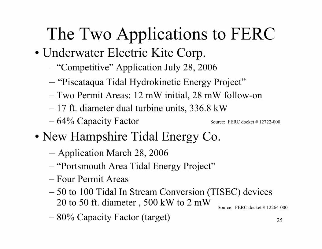
The Two Applications to FERC• Underwater Electric Kite Corp.
– “Competitive” Application July 28, 2006
– “Piscataqua Tidal Hydrokinetic Energy Project”
– Two Permit Areas: 12 mW initial, 28 mW follow-on
– 17 ft. diameter dual turbine units, 336.8 kW
– 64% Capacity Factor
• New Hampshire Tidal Energy Co.
– Application March 28, 2006
– “Portsmouth Area Tidal Energy Project”
– Four Permit Areas
– 50 to 100 Tidal In Stream Conversion (TISEC) devices20 to 50 ft. diameter , 500 kW to 2 mW
– 80% Capacity Factor (target)
Source: FERC docket # 12264-000
Source: FERC docket # 12722-000
26
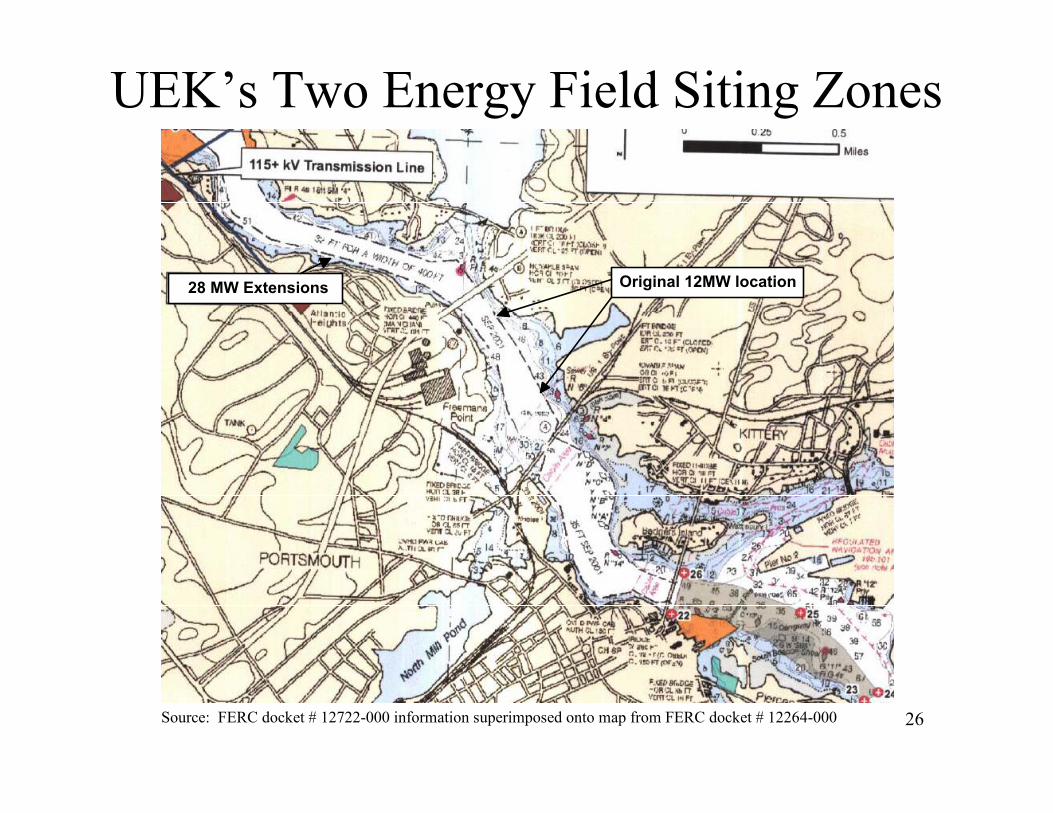
UEK’s Two Energy Field Siting Zones
Source: FERC docket # 12722-000 information superimposed onto map from FERC docket # 12264-000
Original 12MW location28 MW Extensions
27
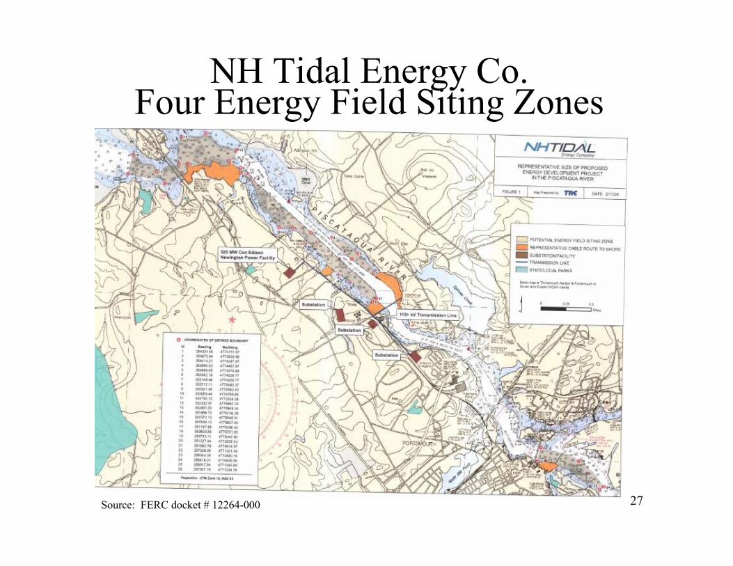
NH Tidal Energy Co. Four Energy Field Siting Zones
Source: FERC docket # 12264-000
28
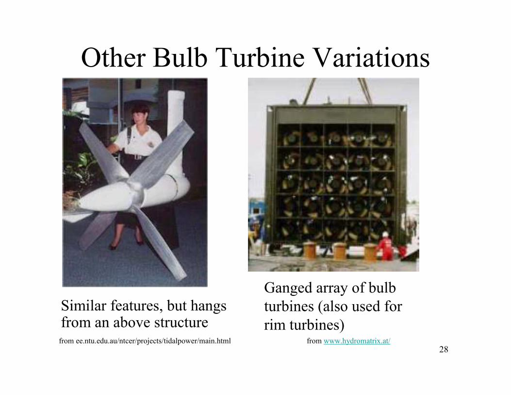
Other Bulb Turbine Variations
Similar features, but hangs from an above structurefrom ee.ntu.edu.au/ntcer/projects/tidalpower/main.html
Ganged array of bulb
turbines (also used for
rim turbines)from www.hydromatrix.at/
29
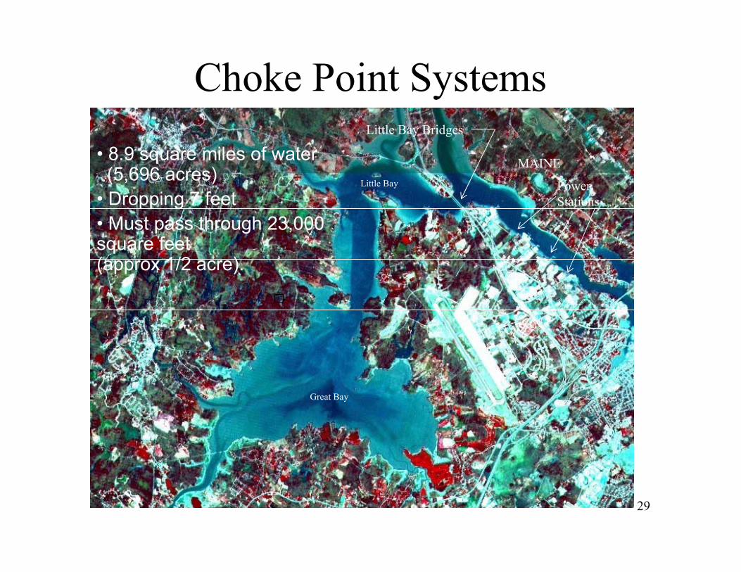
Choke Point Systems
MAINE
Great Bay
Little Bay
Little Bay Bridges
Power
Stations
• 8.9 square miles of water(5,696 acres)
• Dropping 7 feet
• Must pass through 23,000 square feet (approx 1/2 acre).
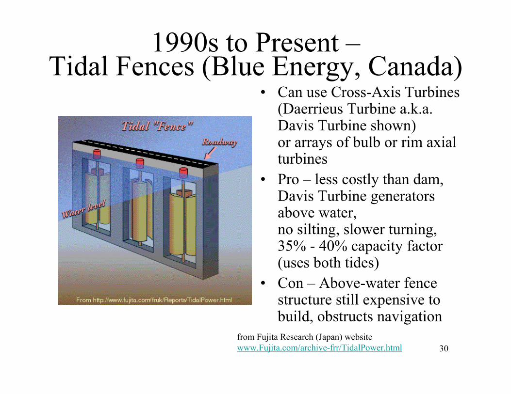
30
1990s to Present –Tidal Fences (Blue Energy, Canada)
• Can use Cross-Axis Turbines(Daerrieus Turbine a.k.a. Davis Turbine shown) or arrays of bulb or rim axial turbines
• Pro – less costly than dam, Davis Turbine generators above water, no silting, slower turning, 35% - 40% capacity factor (uses both tides)
• Con – Above-water fence structure still expensive to build, obstructs navigation
from Fujita Research (Japan) website
www.Fujita.com/archive-frr/TidalPower.html
31
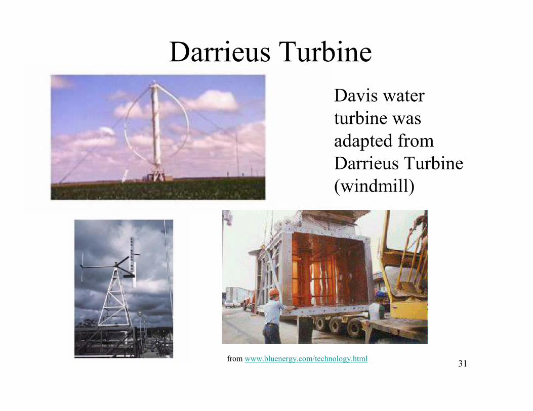
Darrieus Turbine
• Davis water
turbine was
adapted from
Darrieus Turbine
(windmill)
from www.bluenergy.com/technology.html
32
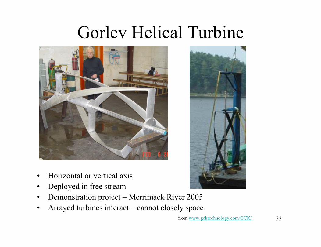
Gorlev Helical Turbine
• Horizontal or vertical axis
• Deployed in free stream
• Demonstration project – Merrimack River 2005
• Arrayed turbines interact – cannot closely space
from www.gcktechnology.com/GCK/
33
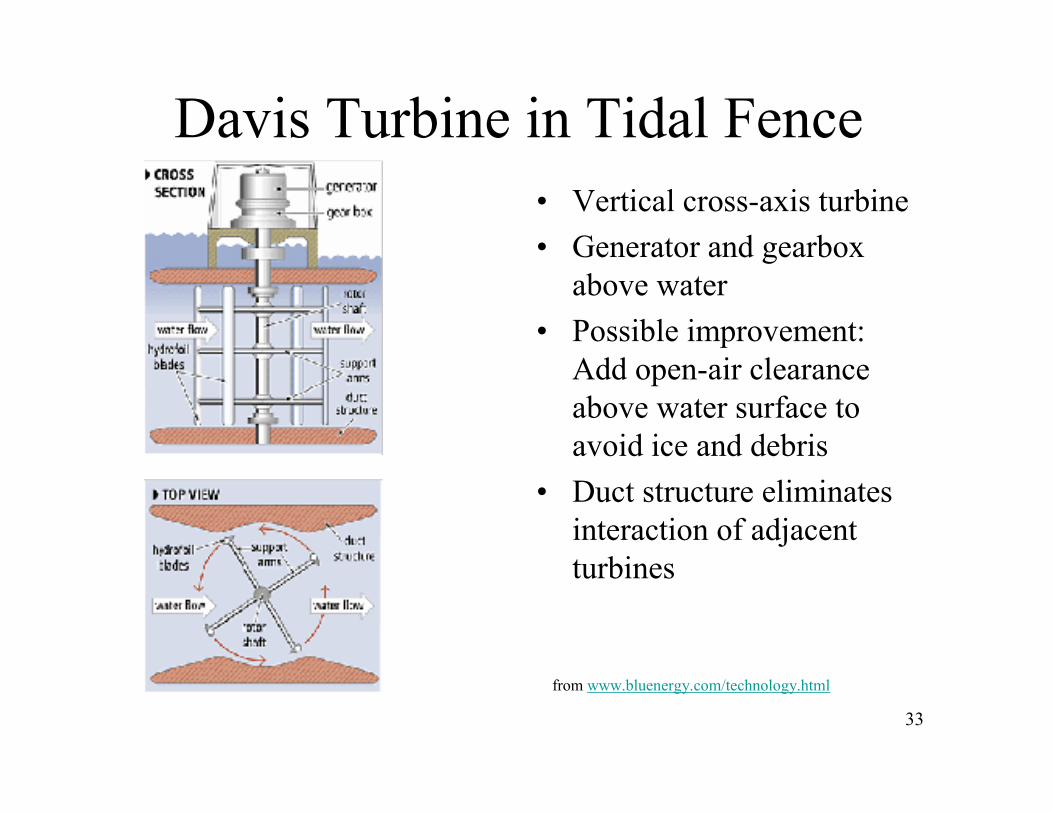
Davis Turbine in Tidal Fence
• Vertical cross-axis turbine
• Generator and gearbox
above water
• Possible improvement:
Add open-air clearance
above water surface to
avoid ice and debris
• Duct structure eliminates
interaction of adjacent
turbines
from www.bluenergy.com/technology.html
34
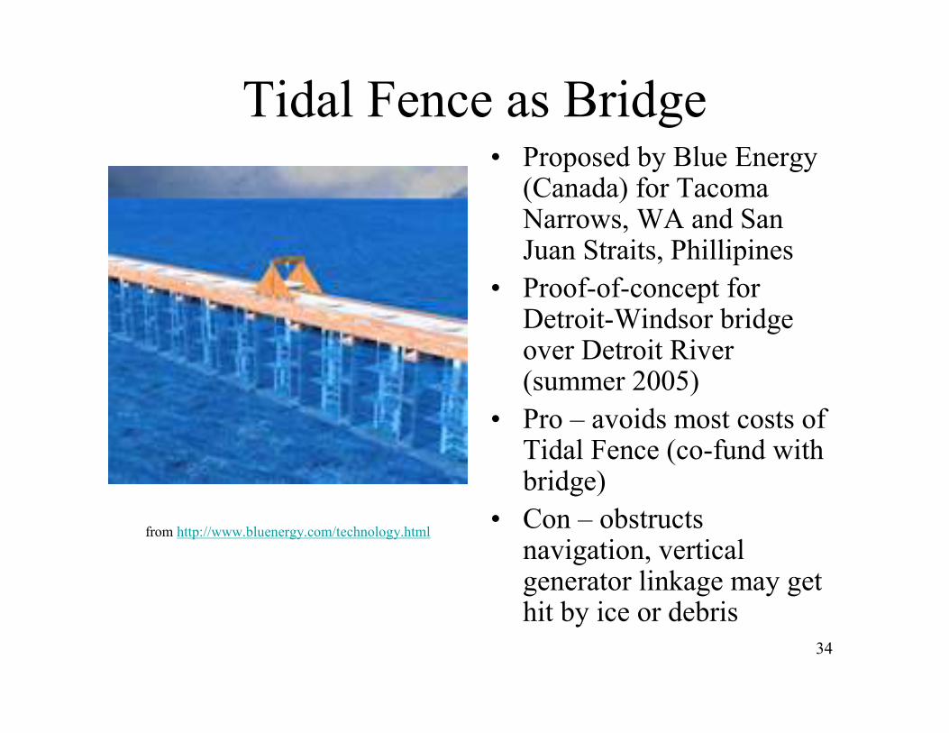
Tidal Fence as Bridge• Proposed by Blue Energy
(Canada) for Tacoma Narrows, WA and San Juan Straits, Phillipines
• Proof-of-concept for Detroit-Windsor bridge over Detroit River (summer 2005)
• Pro – avoids most costs of Tidal Fence (co-fund with bridge)
• Con – obstructs navigation, vertical generator linkage may get hit by ice or debris
from http://www.bluenergy.com/technology.html
35
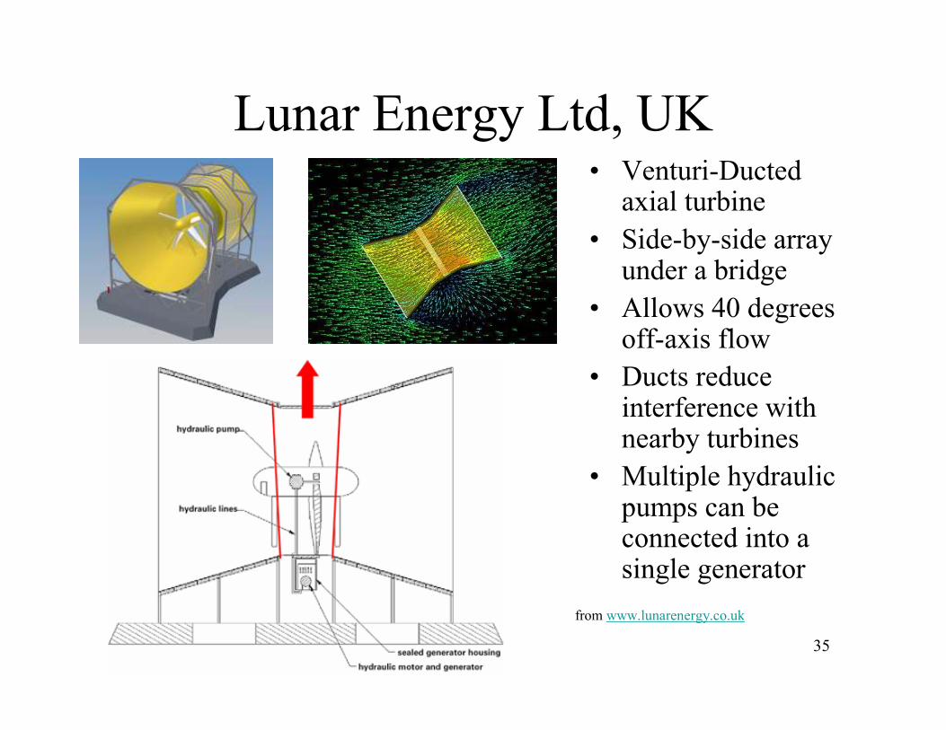
Lunar Energy Ltd, UK• Venturi-Ducted
axial turbine
• Side-by-side array under a bridge
• Allows 40 degrees off-axis flow
• Ducts reduce interference with nearby turbines
• Multiple hydraulic pumps can be connected into a single generator
from www.lunarenergy.co.uk
36
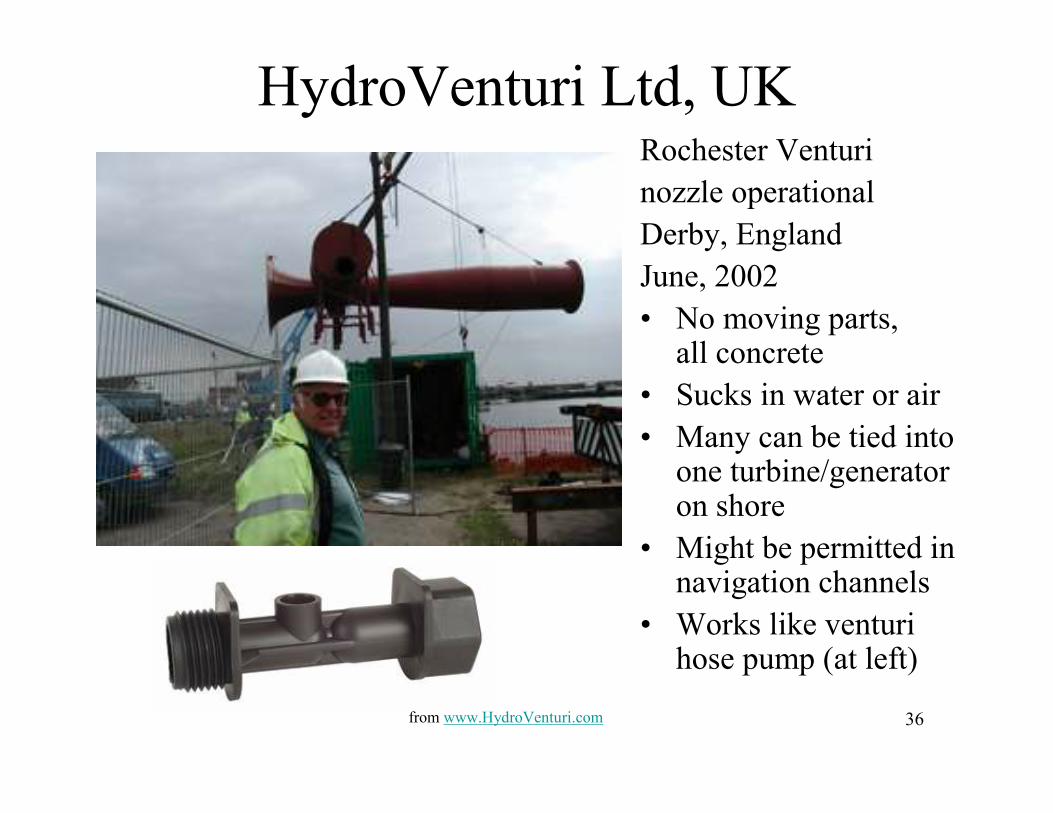
HydroVenturi Ltd, UKRochester Venturi
nozzle operational
Derby, England
June, 2002
• No moving parts, all concrete
• Sucks in water or air
• Many can be tied into one turbine/generator on shore
• Might be permitted in navigation channels
• Works like venturihose pump (at left)
from www.HydroVenturi.com

37
Little Bay Bridges site
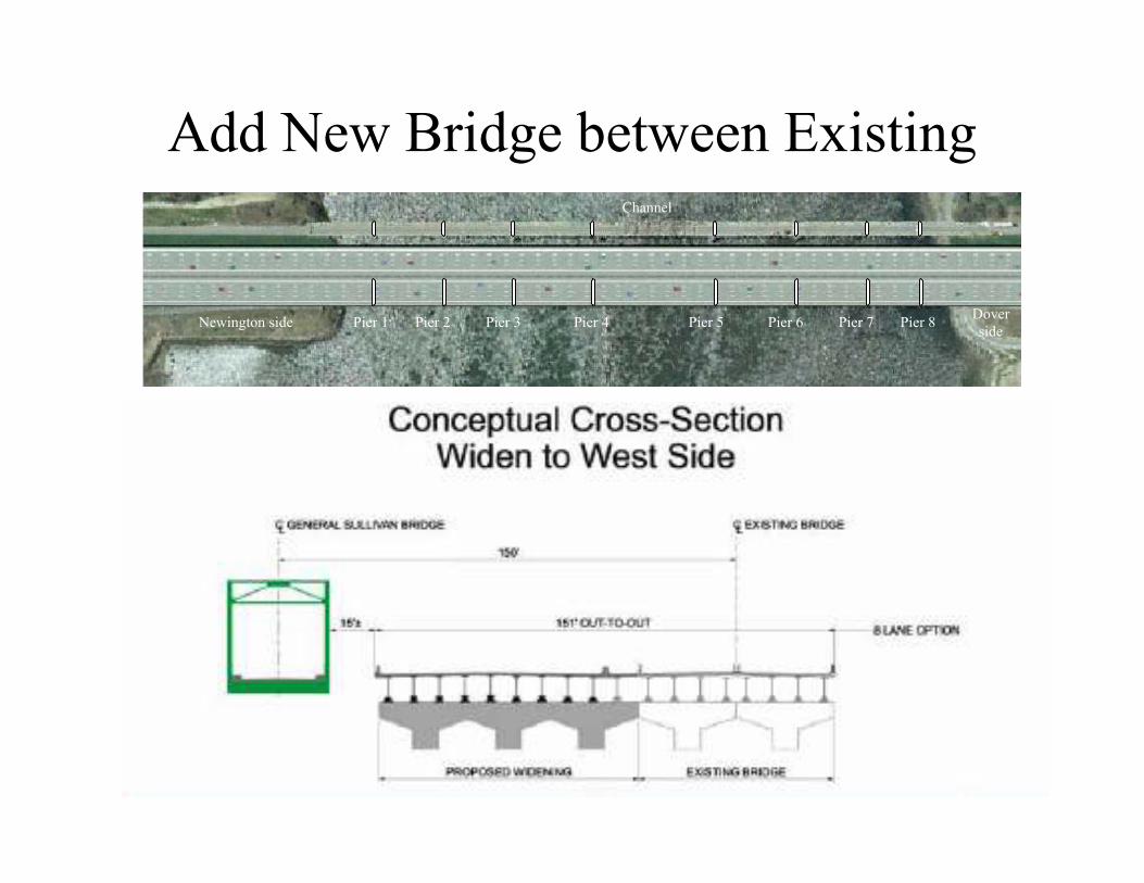
• New bridge to be added between the existing two
http://www.newington-dover.com/images/photo11.jpg
38
Add New Bridge between Existing
Newington side Pier 1 Pier 2 Pier 3 Pier 4 Pier 5 Pier 6 Pier 7 Pier 8Dover
side
Channel
39
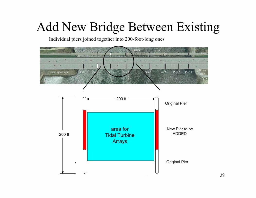
Add New Bridge Between ExistingIndividual piers joined together into 200-foot-long ones
Newington side Pier 1 Pier 2 Pier 3 Pier 4 Pier 5 Pier 6 Pier 7 Pier 8Dover
side
Channel
Original Pier
Original Pier
New Pier to be
ADDED200 ft
200 ft
area for
Tidal Turbine
Arrays
40
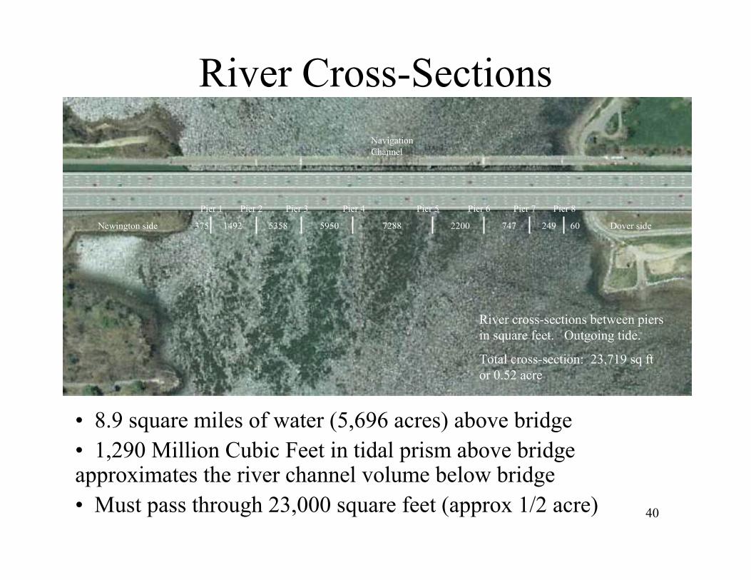
River Cross-Sections
Newington side
Pier 1 Pier 2 Pier 3 Pier 4 Pier 5 Pier 6 Pier 7 Pier 8
Dover side375 1492 5358 5950 7288 2200 747 249 60
Navigation
Channel
River cross-sections between piers
in square feet. Outgoing tide.
Total cross-section: 23,719 sq ft
or 0.52 acre
• 8.9 square miles of water (5,696 acres) above bridge
• 1,290 Million Cubic Feet in tidal prism above bridge approximates the river channel volume below bridge
• Must pass through 23,000 square feet (approx 1/2 acre)

41
Current at Little Bay Bridges• Two-knot “stall point” is less than 25 minutes
• Zero velocity seldom exceeds 10 minutes
• Can yield a capacity factor of around 60%
fastest
current
slack
high
(no current)
slack low
(no current)
slack low
(no current)
slack low
(no current)
fastest
current
fastest
currentfastest
current
slack
high
(no current)
Tide H
eight
Power Output
Max
Time
A Real World Bi-directional Tidal Power Generator
Turbine stalls when when current is almost slack.
Time
42
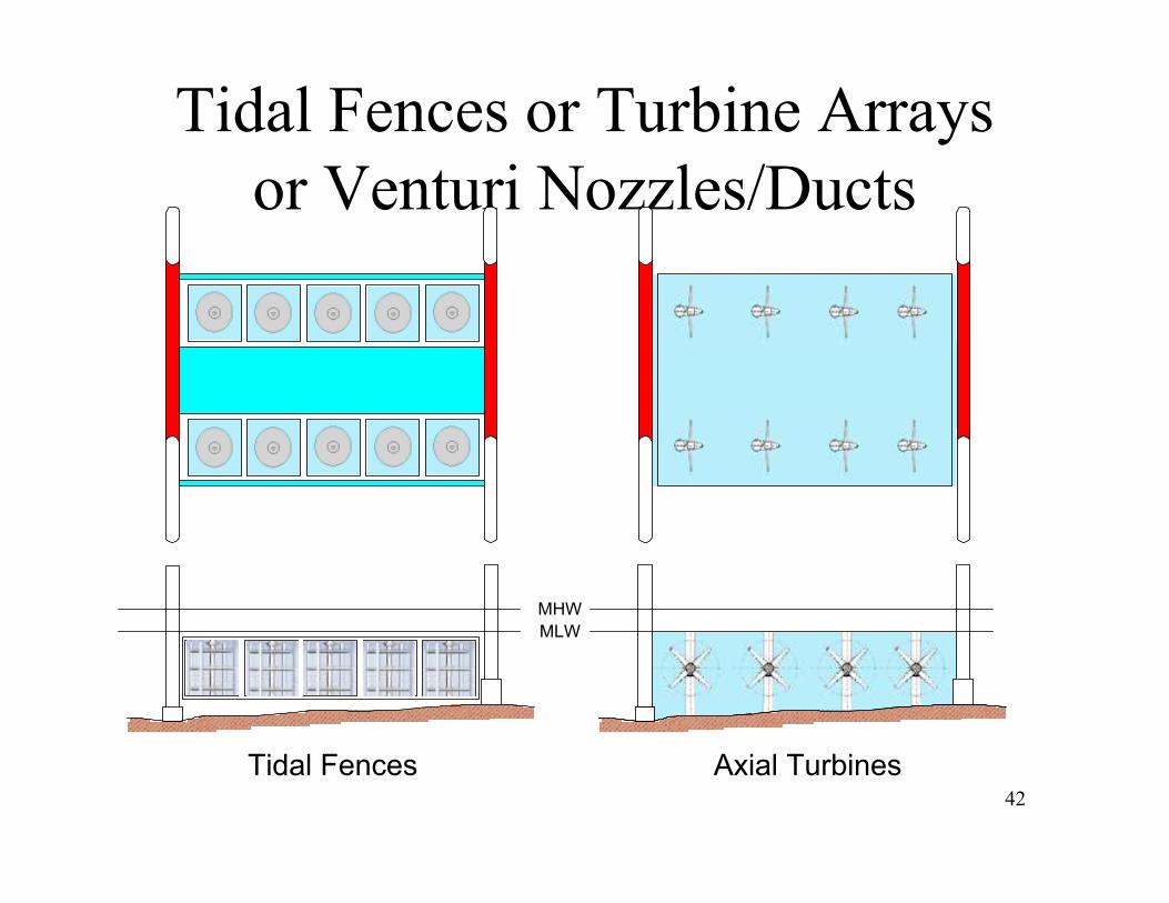
Tidal Fences or Turbine Arrays
or Venturi Nozzles/Ducts
MHW
MLW
Tidal Fences Axial Turbines