Embed Size (px)
Citation preview

June 2005 ITU/BDT NGN Network Architecture - O.G.S. - slide 1
ITU/BDT ITU/BDT RegionalRegional Seminar Seminar onon
Costs and Tariffs for Member Countries of the Tariff Group Costs and Tariffs for Member Countries of the Tariff Group for Africafor Africa (TAF)(TAF)
MidrandMidrand, South Africa, June 2005, South Africa, June 2005
NGN Network Architecture
Oscar González SotoITU Consultant Expert
Strategic Planning and Assessment
June 2005 ITU/BDT NGN Network Architecture - O.G.S. - slide 2
NGN NGN NetworkNetwork Architecture Architecture Content Content
• NGN concepts • Concepts and motivation
• Requirements
• Network architecture• Functional Network
• Network elements and protocols
• Network design issues• Dimensioning for multiple flows
• Cost drivers and trends

June 2005 ITU/BDT NGN Network Architecture - O.G.S. - slide 3
NGN NGN NetworkNetwork ArchitectureArchitectureNGN concept
•A multi-service network able to support voice, data and video
•A network with a control plane (signaling, control) separated from
the transport/switching plane
•A network with open interfaces between transport, control and
applications
•A network using packet mode technology to transport of all kind
of information
•A network with guaranteed QoS for different traffic types and SLAs

June 2005 ITU/BDT NGN Network Architecture - O.G.S. - slide 4
NGN NGN NetworkNetwork ArchitectureArchitectureWhyWhy
• Flexibility for service building and offering
• Expectation of cost reductions by sharing infrastructure and
systems
• Simplification of O&M, thus lowering OPEX.
• Use of open interfaces leads for:
- quick deployment of services and applications
- new services (third parties)

June 2005 ITU/BDT NGN Network Architecture - O.G.S. - slide 5
NGN NGN NetworkNetwork ArchitectureArchitectureNGN LayersNGN Layers
NetworkIndependent
Services
Legacy Network Signaling/Service
Legacy Network Media

June 2005 ITU/BDT NGN Network Architecture - O.G.S. - slide 6
NGN NGN NetworkNetwork ArchitectureArchitectureTargetTarget architecturearchitecture
OtherNetworks
DLC
Control
Transport/Media Distributed Switching
DSL
TrunkgatewayAccess
gateway
Wirelessgateway
Accessgateway
Accessgateway
Softswitch
OSS Services
PacketNetwork

June 2005 ITU/BDT NGN Network Architecture - O.G.S. - slide 7
NGN NGN NetworkNetwork ArchitectureArchitectureKey Factors: Operator Requirements(I)Key Factors: Operator Requirements(I)
• Business continuity required to maintain ongoing dominant services and customers that require carrier-grade service
• Flexibility to incorporate existing new services and react quickly to theones that appear on real time (main advantage of IP mode)
• Profitability to allow feasible return on investments and in the best practices market values

June 2005 ITU/BDT NGN Network Architecture - O.G.S. - slide 8
NGN NGN NetworkNetwork ArchitectureArchitectureKey Factors: Operator Requirements (II)Key Factors: Operator Requirements (II)
• Survivabilty to allow service assurance in case of failures and externalunexpected events
• Quality of Service to guarantee the Service Level Agreements for different traffic mixes, conditions and overload.
• Interoperabilty across networks to allow to carry end to end services for flows in different network domains

June 2005 ITU/BDT NGN Network Architecture - O.G.S. - slide 9
NGN NGN NetworkNetwork Architecture Architecture Content Content
• NGN concepts • Concepts and motivation
• Requirements
• Network architecture• Functional Network
• Network elements and protocols
• Network design issues• Dimensioning for multiple flows
• Cost drivers and trends

June 2005 ITU/BDT NGN Network Architecture - O.G.S. - slide 10
NGN NGN NetworkNetwork ArchitectureArchitectureNetwork ArchitectureNetwork Architecture
PBX
SoftswitchMedia Gateway
Controller
IP/XX Network
Intelligent NetworkAppl. Servers
Access Gateway
Access Gateway
N7 Signalling
PSTN
Access Gateway
TrunkingGateway
H.248
H.248H.248
H.248

June 2005 ITU/BDT NGN Network Architecture - O.G.S. - slide 11
NGN NGN NetworkNetwork ArchitectureArchitectureNetwork ElementsNetwork Elements
• Packet based networks– Trend is to use IP based networks over various transport possibilities (ATM, SDH, WDM…)– IP based networks must offer guarantees of Quality of Service (QoS) regarding the real time characteristics of voice, video and multimedia
• Access Gateways– Allows the connection of subscriber lines to the packet network– Converts the traffic flows of analogue access (Pots) or 2 Mb/s access devices into packets – Provides subscriber access to NGN network and services
• Trunking Gateways– Allows interworking between classical TDM telephony network and Packet-based NGN networks, – Converts TDM circuits/ trunks (64kbps) flows into data packets, and vice versa

June 2005 ITU/BDT NGN Network Architecture - O.G.S. - slide 12
NGN NGN NetworkNetwork ArchitectureArchitectureNetwork Elements Network Elements
• Softswitch/MGC
– referred to as the Call Agent or Media Gateway Controller (MGC).
– provides the “service delivery control” within the network
– in charge of Call Control and handling of Media Gateways control (Access and/or Trunking) via H.248 protocol
– performs signalling gateway functionality or uses a signalling gateway for interworking with PSTN N7 signalling network
– provides connection to Intelligent Network /applications servers to offer the same services as those available to TDM subscribers
• Application Server (AS):– A unit that supports service execution, e.g. to control Call Servers and NGN special resources (e.g. media server, message server).
June 2005 ITU/BDT NGN Network Architecture - O.G.S. - slide 13
NGN NGN NetworkNetwork ArchitectureArchitectureNetwork Elements Network Elements
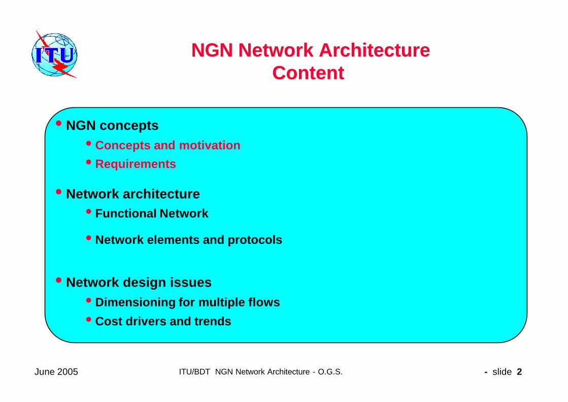
• H.248 Protocol
– Known also as MEGACO: standard protocol, defined by ITU-T, for signalling and session management needed during a communication between a media gateway, and the media gateway controller managing it
– H.248/MEGACO allows to set up, keep, and terminate calls between multiple endpoints as between telephone subscribers using the TDM
• SIP– Session Initiation Protocol in order to handle call establishment, maintenance and termination from packet mode terminals.
• Signalling Gateway (SG):
– A unit that provides signalling conversion between the NGN and the other networks (e.g. STP in SS7).

June 2005 ITU/BDT NGN Network Architecture - O.G.S. - slide 14
NGN NGN NetworkNetwork ArchitectureArchitectureNetwork Elements Network Elements
• ENUM– Electronic NUMbering: Protocol that allows to establish a correspondance betweenthe traditional telafone numbering (E.164 ) and the network addresses related to thepacket mode networks ( RFC 2916 "E.164 number and DNS" IETF).
• MPLS– Multiprotocol Label Switch or protocol that assigns labels to information packets in order to allow the node routers to treat and route flows in the network paths according to established priority for each category.
• CAC
– Call Acceptance Control function in order to accept/reject traffic in the network that allows guarantee of QoS for services with a Service Level Agreement
• BGP– Border Gateway Protocol to negotiate flow routing procedures and capacities across different NGN network domains

June 2005 ITU/BDT NGN Network Architecture - O.G.S. - slide 15
NGN NGN NetworkNetwork ArchitectureArchitectureArchitecture Consolidation: Topology Architecture Consolidation: Topology
Topological changes impact on infrastructure and are slower to implement than technology substitution
• Less network nodes and links due to the higher capacity of systems (one order of magnitude).
• Same capilarity at access level due to identical customer location
• Topological connectivity higher for high capacity nodes and paths for security
• High protection level and diversity paths/sources in all high capacity systems, both at functional and physical levels

June 2005 ITU/BDT NGN Network Architecture - O.G.S. - slide 16
Smooth migration to NGNSmooth migration to NGNNGN NGN NetworkNetwork ArchitectureArchitectureOverall Architecture Overall Architecture
MultiserviceNode
AccessAccess
CustomersCustomers
CoreCorePSTN Class 4
Subscriber unit
RSP
DS
DataMux
IN
EdgeEdgePSTN Class 5
SSP
InternationalInternationalCoreCore
June 2005 ITU/BDT NGN Network Architecture - O.G.S. - slide 17
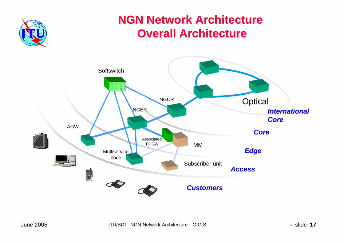
NGN NGN NetworkNetwork ArchitectureArchitectureOverall Architecture Overall Architecture
Multiservicenode
AccessAccess
CustomersCustomers
CoreCore
Subscriber unit
MM
NGCR Optical
AGW
Softswitch
AssociatedTK GW
EdgeEdge
International International CoreCore
NGER
June 2005 ITU/BDT NGN Network Architecture - O.G.S. - slide 18
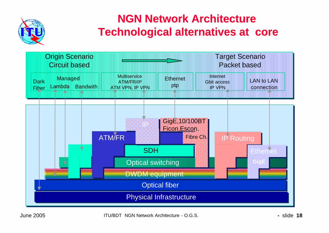
NGN NGN NetworkNetwork ArchitectureArchitectureTechnological alternatives at coreTechnological alternatives at core
Lambda BandwithDarkFiber
Origin Scenario Circuit based
Target Scenario Packet based
Managed Multiservice ATM/FR/IP
ATM VPN, IP VPN
Ethernet ptp
LAN to LANconnection
Internet Gbit access
IP VPN
Optical fiberOptical fiberDWDM equipmentDWDM equipmentOptical switchingOptical switching
SDHSDH
IP RoutingIP Routing
EthernetEthernetGigEGigE
ATM/FRATM/FR
GigE,10/100BTFicon,Escon, GigE,10/100BTFicon,Escon,
FibreFibre Ch..Ch..
IPIP
Physical InfrastructurePhysical Infrastructure

June 2005 ITU/BDT NGN Network Architecture - O.G.S. - slide 19
NGN NGN NetworkNetwork Architecture Architecture Content Content
• NGN concepts • Concepts and motivation
• Requirements
• Network architecture• Functional Network
• Network elements and protocols
• Network design issues• Dimensioning for multiple flows
• Cost drivers and trends

June 2005 ITU/BDT NGN Network Architecture - O.G.S. - slide 20
NGN NGN NetworkNetwork Architecture Architecture The Network Design Criteria The Network Design Criteria
• A) Match realistic service demands and workloads for a given time
– Node and links loads based on proper multiservice flow
characterization, measurements and projections
• B) Consider equilibrium between QoS and cost
– Statistical behavior for the flows
– Traffic modeling for given quality, efficiency and protection
– Overload protection and control
• C) Anticipate capacity as a function of service grow rate and needed
installation time. Reserve capacity
• D) Follow SLA when different service classes coexist

June 2005 ITU/BDT NGN Network Architecture - O.G.S. - slide 21
NGN NGN NetworkNetwork Architecture Architecture Network Design Network Design andand DimensioningDimensioning
The 5 basic Traffic activitiesThe 5 basic Traffic activities
• Traffic Characterization for services and network flows
• Traffic Demand forecasting and aggregation at the user and Network interfaces
• Traffic Dimensioning for all network elements
• Traffic Measurements and Validation for key parameters
• Traffic Management in focussed and generalized overload

June 2005 ITU/BDT NGN Network Architecture - O.G.S. - slide 22
NGN NGN NetworkNetwork Architecture Architecture Network Design Network Design andand DimensioningDimensioning
Service demand Characterization
– By a profile through days in a year/week
– By a busy period within a day
– By superposition of non-coincidence of busy periods (for inter-
country traffic in different time zone)
– By aggregation or convolution of flows for different services
– By interest factors between areas (adjusting matrices in the two
dimensions ie: Kruithof, affinity, correlation)

June 2005 ITU/BDT NGN Network Architecture - O.G.S. - slide 23
NGN NGN NetworkNetwork Architecture Architecture Traffic Characterization Traffic Characterization
• Aggregated average traffic per level as a weighted average of the services (i) and customer classes (j) at that level.
• Generalized utilization time and levels per user activityin the busy period : Example for IP mode
Activity/Connection time at Application level
Customer Service time at Session level
Communication time at Burst level
Transmission time at Packet level

June 2005 ITU/BDT NGN Network Architecture - O.G.S. - slide 24
NGN NGN NetworkNetwork ArchitectureArchitectureTrafficTraffic CharacterizationCharacterization
• Different relation between peak traffic and average traffic per service classes:CBR (1), VBR(2), VBR(3)

June 2005 ITU/BDT NGN Network Architecture - O.G.S. - slide 25
NGN NGN NetworkNetwork Architecture Architecture Traffic Characterization Traffic Characterization
• Traffic Units definition– At call, session and packet level – Needed additional clarification on the different type of traffic averages
and meaning (CBR,SBR, Billed)
• Reference periods– Should be common when aggregating services to ensure validity and
represent behavior of IP flows• Statistical laws
– For calls, sessions and packets
• Aggregation process – Considering reference period above and coincidence/non-
coincidence of busy periods among services

June 2005 ITU/BDT NGN Network Architecture - O.G.S. - slide 26
NGN NGN NetworkNetwork Architecture Architecture TrafficTraffic flowflow typestypes forfor QualityQuality ofof ServiceService
basedbased dimensioningdimensioning
– QoS constant stream: bandwidth transmission at a constant speed with a specified delivery and jitter (ie: video distribution)
– QoS variable stream : bandwidth transmission at a variable speed derived from a user information and coding algorithm whichrequires guaranteed quality and specified jitter (ie: VoIP, Video streaming, audio streaming, etc.)
– QoS elastic: bandwidth transmission at a variable speed without jitter restrictions and asynchronous delivery (ie: browsing, file transfer, mail, UMS, etc.)

June 2005 ITU/BDT NGN Network Architecture - O.G.S. - slide 27
NGN NGN NetworkNetwork Architecture Architecture Traffic Flows to be modeledTraffic Flows to be modeled
• L1) Global Network Level
– Overall topological network (access and/or core) including routing procedures and all alternative paths.
• L2) End to End Path or sub-path
– For different user type scenarios: VoIP to VoIP, VoIP to POTS, etc. and network segments: user to LEX, user to GW, etc.
• L3) Network Elements
– For Network Nodes
• LEX, RSU,POP,GW, SS, TGW,IP router, etc.
– Network Links
• At functional, transmission and physical levels
To simplify analysis, the following partition is made:

June 2005 ITU/BDT NGN Network Architecture - O.G.S. - slide 28
NGN NGN NetworkNetwork Architecture Architecture NGN NGN ServiceService demanddemand evaluationevaluation processprocess
Traffic aggregation per O/D and flow category
Traffic matrices
Services per customer type Traffic per service/customer typeServices projectionMapping services per customer
Traffic units per service (multi-service IP)Traffic aggregation per customer type
Traffic aggregation per IP flow categoryTraffic flow aggregation per O/D
Matrix per IP flow category (original BW)Dimensioning matrix (capacity BW)

June 2005 ITU/BDT NGN Network Architecture - O.G.S. - slide 29
NGN NGN NetworkNetwork ArchitectureArchitectureCost drivers and trendsCost drivers and trends
• Network physical infrastructure as a function of location and density (costs proportion around 70% in the access segment)
• Volume of customers per category
• Bandwidth demand per origin/destination
• Packet processing rates for control related functions
• Variety of applications/services and related platforms
• Content storage and location within the network
• Leasing of physical or communication resources
Fundamental importance of economies of scale by volume and convergence at network resources, service platforms and OSS

June 2005 ITU/BDT NGN Network Architecture - O.G.S. - slide 30
NGN NGN NetworkNetwork ArchitectureArchitectureCost drivers and trendsCost drivers and trends
Cost trends for NGN
• Cost reduction in CAPEX due to technological economy of scale by larger capacities
• Similar values for costs in the physical civil infrastructure
• OPEX in NGN trends to be lower due to the integrated operation and maintenance
• Plan higher investments in security/survivability with diversity paths and protection for large capacity systems
Check and validate correct cost modelling with fixed and variable components as a function of economy of scale

June 2005 ITU/BDT NGN Network Architecture - O.G.S. - slide 31
NGN NGN NetworkNetwork ArchitectureArchitectureSummary of Key ConceptsSummary of Key Concepts
• Multimedia open service network.
• Applications and control functions separated from media
• Guarantee of Quality of Service needed
• Motivated by new services, flexibility and cost reductions
• Maturity level progressing and needing consolidation