Embed Size (px)
Citation preview
New Rolling Method f Reversing Cold Rolling Mill
Tanehiro Kikkawa JP Steel Plantech Co.,
3-1, Kinko-cho, Kanagawa-ku, Yokohama 221-0056, Japan
Tel: +81-45-440-5942 Fax: +81-45-440-5867
Email: [email protected]
Key words: Zoom-MillTM, Off-gauge, Minimization, Yield, Productivity, Leader strip, Spot welding
INTRODUCTION
For production of cold rolling steel strips in the size of yearly production capacity ranged from 150 to 300 thousands tons, a reversing cold rolling mill, which takes relatively inexpensive capital investment, is put into use. The reversing cold rolling mill is used mainly for producing coils of normal carbon steel in emerging countries, and is used for producing small lots of variety coils of high-grade steel or special steel in advanced countries. Since not being continuous rolling, the reversing cold rolling mill has had drawbacks such that unrolled portions necessarily produced in head and tail ends reduce yield, and time consuming works such as replacement of coils, threading of the strip and holding of the strip with the winding reel decrease productivity. In this article, the development of a new rolling method (Zoom-MillTM, Zero-oriented off-gauge minimization) that enables unrolled portions to be reduced using a leader strip and a spot welding machine and thereby aims improvement of productivity will be presented.
OUTLINE OF REVERSING COLD ROLLING MILL
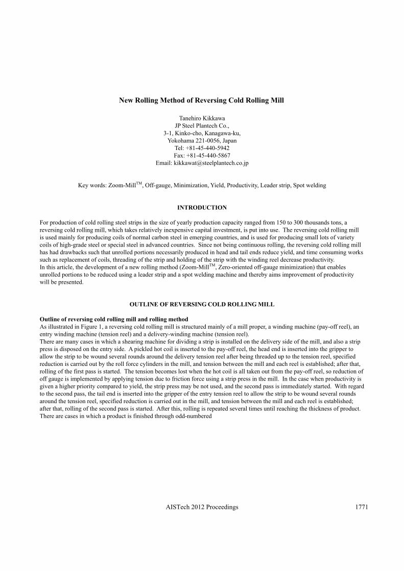
Outline of reversing cold rolling mill and rolling method As illustrated in Figure 1, a reversing cold rolling mill is structured mainly of a mill proper, a winding machine (pay-off reel), an entry winding machine (tension reel) and a delivery-winding machine (tension reel). There are many cases in which a shearing machine for dividing a strip is installed on the delivery side of the mill, and also a strip press is disposed on the entry side. A pickled hot coil is inserted to the pay-off reel, the head end is inserted into the gripper to allow the strip to be wound several rounds around the delivery tension reel after being threaded up to the tension reel, specified reduction is carried out by the roll force cylinders in the mill, and tension between the mill and each reel is established; after that, rolling of the first pass is started. The tension becomes lost when the hot coil is all taken out from the pay-off reel, so reduction of off gauge is implemented by applying tension due to friction force using a strip press in the mill. In the case when productivity is given a higher priority compared to yield, the strip press may be not used, and the second pass is immediately started. With regard to the second pass, the tail end is inserted into the gripper of the entry tension reel to allow the strip to be wound several rounds around the tension reel, specified reduction is carried out in the mill, and tension between the mill and each reel is established; after that, rolling of the second pass is started. After this, rolling is repeated several times until reaching the thickness of product. There are cases in which a product is finished through odd-numbered
AISTech 2012 Proceedings 1771
Figure 1. Conventional rolling method of a reversing cold rolling mill
AISTech 2012 Proceedings1772
passes such as one pass, three passes, five passes, and so on, or cases in which a product is finished through even-numbered passes such as two passes, four passes, six passes, and so on; however, the case in which a product is finished mainly through odd-numbered passes seems to be often realized because of the constraint from the equipment constituting the line, the constraint from the flow being continued to the following line, or the like. A final process illustrated in Figure 1 is an example in which a product coil is taken out from the delivery tension reel after being subjected to odd-numbered passes. Although a portion that does not become a product because of not being rolled (off-gauge portion) is included in the end on both sides in the longitudinal direction (i.e., the entry side and the delivery side) of a strip, the end on the entry side is cut out by means of a shearing machine on the delivery side of the mill and is taken out from the entry tension reel as a small coil (pup coil) to be disposed. On the other hand, an off-gauge portion in the end on the delivery side remains in the inner periphery of the product coil taken out from the delivery tension reel, and is disposed in the following line or by an end user. (2) Conventional technology for reducing an unrolled portion Hitherto, there have been proposed various kinds of measures for reducing an unrolled portion (off-gauge portion) produced on both ends of rolled material in the longitudinal direction. One of these is a method such that rolling is carried out with no tensioning in a state in which the both ends of the material in the longitudinal direction are each released from the tension reel, and after that, reverse rolling is continuously continued by holding the material again with the tension reel 1). Since this method is to carry out rolling without tensioning any portion near both ends, there is a fear that strip threading becomes unstable, or the shape and/or thickness of the strip become worse. Moreover, since the rolling without tensioning is carried out in a low speed and it takes time to have a strip held by and released from the tension reel, reduction in productivity is unavoidable. The second one is such an example that a coil preparation line is provided in next to reversible rolling equipment 2). In the coil preparation line, there are carried out works to make a coil to be prolonged by weld-joining respective ends of the strip with each other, or to weld a dummy member (leader piece) to both ends of the strip. This method needs installation costs, a broad (long) installation area, operating personnel and running costs aside from rolling facilities.
DEVELOPMENT OF Zoom-MillTM USING A LEADER STRIP AND A SPOT WELDER
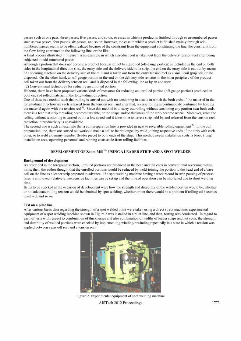
Background of development As described in the foregoing section, unrolled portions are produced in the head and tail ends in conventional reversing rolling mills; then, the author thought that the unrolled portions would be reduced by weld-joining the portion to the head end of a base coil on the line as a leader strip prepared in advance. If a spot welding machine having a track record in strip passing of process lines is employed, relatively inexpensive facilities can be set up and the time of operation can be shortened due to short welding time. Items to be checked at the occasion of development were how the strength and durability of the welded portion would be, whether or not adequate rolling tension would be obtained by spot welding, whether or not there would be a problem if rolling oil becomes involved, and so on. Test on a pilot line After various basic data regarding the strength of a spot welded point were taken using a direct stress machine, experimental equipment of a spot welding machine shown in Figure 2 was installed in a pilot line, and then, testing was conducted. In regard to each of tests with respect to combination of thicknesses and also combination of widths of leader strips and hot coils, the strength and durability of welded portions were checked by implementing winding/rewinding repeatedly in a state in which a tension was applied between a pay-off reel and a tension reel.
Figure 2. Experimental equipment of spot welding machine
AISTech 2012 Proceedings 1773
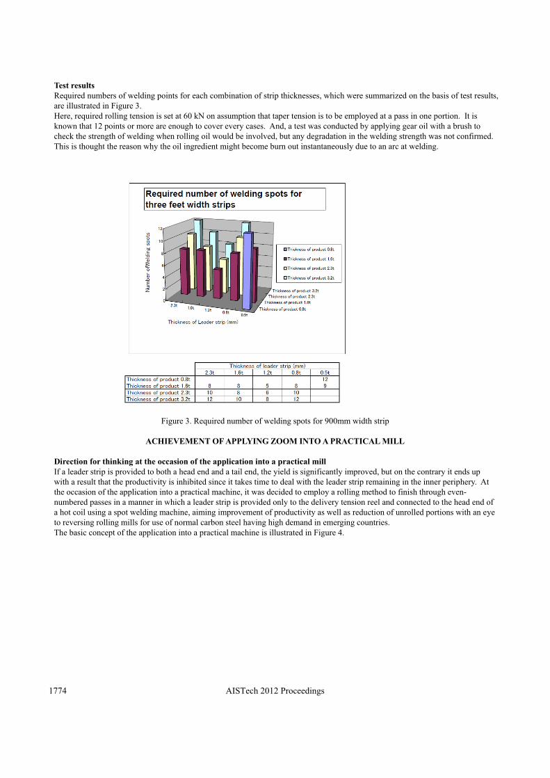
Test results Required numbers of welding points for each combination of strip thicknesses, which were summarized on the basis of test results,are illustrated in Figure 3. Here, required rolling tension is set at 60 kN on assumption that taper tension is to be employed at a pass in one portion. It is known that 12 points or more are enough to cover every cases. And, a test was conducted by applying gear oil with a brush to check the strength of welding when rolling oil would be involved, but any degradation in the welding strength was not confirmed.This is thought the reason why the oil ingredient might become burn out instantaneously due to an arc at welding.
Figure 3. Required number of welding spots for 900mm width strip
ACHIEVEMENT OF APPLYING ZOOM INTO A PRACTICAL MILL
Direction for thinking at the occasion of the application into a practical mill If a leader strip is provided to both a head end and a tail end, the yield is significantly improved, but on the contrary it ends up with a result that the productivity is inhibited since it takes time to deal with the leader strip remaining in the inner periphery. At the occasion of the application into a practical machine, it was decided to employ a rolling method to finish through even-numbered passes in a manner in which a leader strip is provided only to the delivery tension reel and connected to the head end of a hot coil using a spot welding machine, aiming improvement of productivity as well as reduction of unrolled portions with an eye to reversing rolling mills for use of normal carbon steel having high demand in emerging countries. The basic concept of the application into a practical machine is illustrated in Figure 4.
AISTech 2012 Proceedings1774
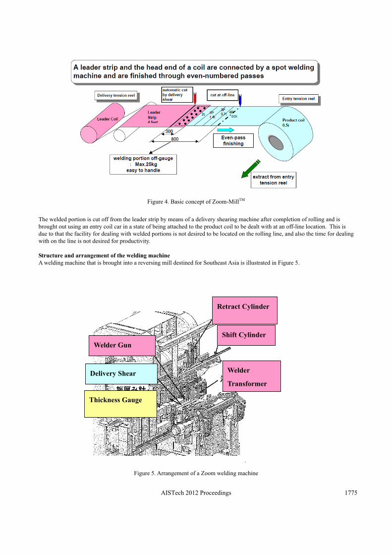
Figure 4. Basic concept of Zoom-MillTM
The welded portion is cut off from the leader strip by means of a delivery shearing machine after completion of rolling and is brought out using an entry coil car in a state of being attached to the product coil to be dealt with at an off-line location. This is due to that the facility for dealing with welded portions is not desired to be located on the rolling line, and also the time for dealing with on the line is not desired for productivity. Structure and arrangement of the welding machine A welding machine that is brought into a reversing mill destined for Southeast Asia is illustrated in Figure 5.
Figure 5. Arrangement of a Zoom welding machine
Retract Cylinder
Shift Cylinder
Welder
Transformer
Welder Gun
Delivery Shear
Thickness Gauge
AISTech 2012 Proceedings 1775
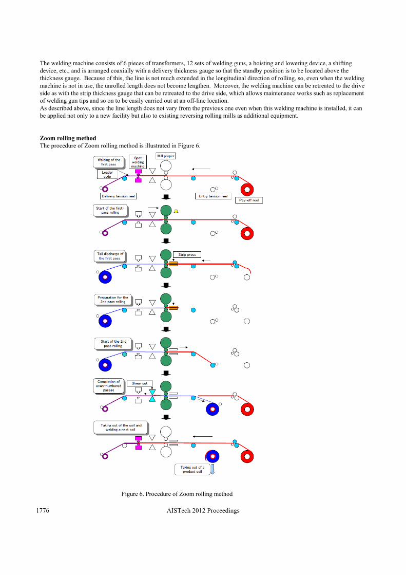
The welding machine consists of 6 pieces of transformers, 12 sets of welding guns, a hoisting and lowering device, a shifting device, etc., and is arranged coaxially with a delivery thickness gauge so that the standby position is to be located above the thickness gauge. Because of this, the line is not much extended in the longitudinal direction of rolling, so, even when the welding machine is not in use, the unrolled length does not become lengthen. Moreover, the welding machine can be retreated to the drive side as with the strip thickness gauge that can be retreated to the drive side, which allows maintenance works such as replacement of welding gun tips and so on to be easily carried out at an off-line location. As described above, since the line length does not vary from the previous one even when this welding machine is installed, it can be applied not only to a new facility but also to existing reversing rolling mills as additional equipment. Zoom rolling method The procedure of Zoom rolling method is illustrated in Figure 6.
Figure 6. Procedure of Zoom rolling method
AISTech 2012 Proceedings1776
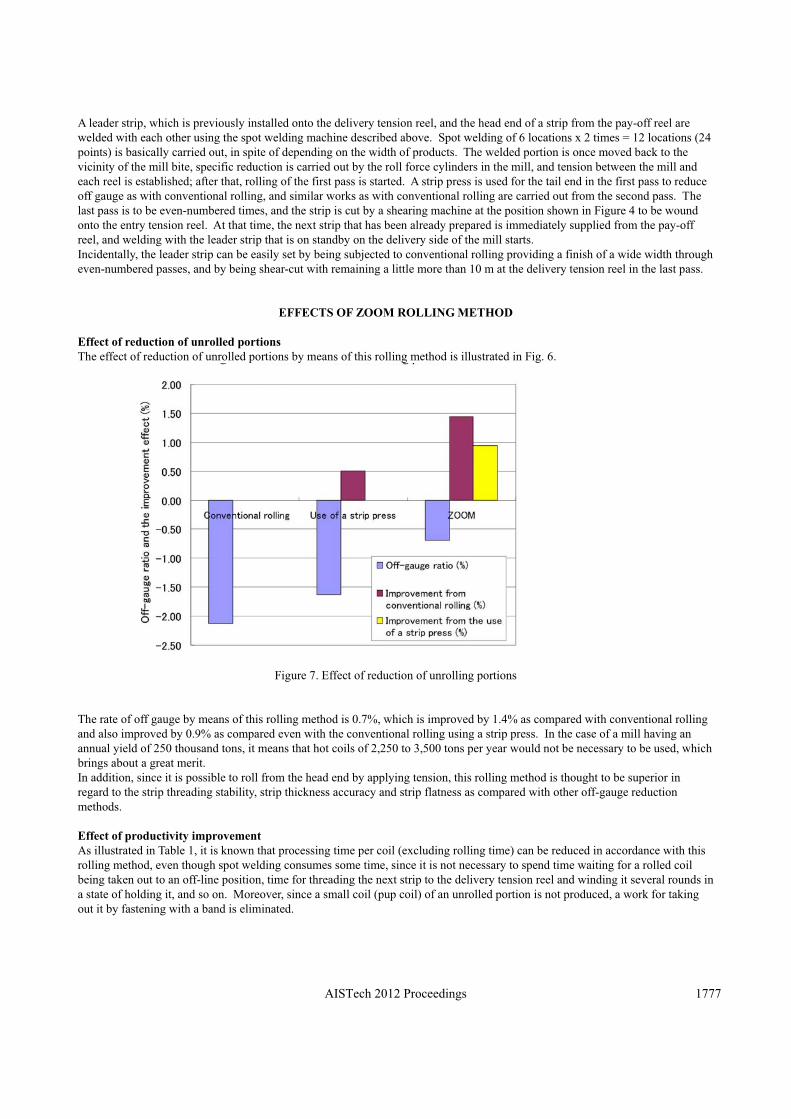
A leader strip, which is previously installed onto the delivery tension reel, and the head end of a strip from the pay-off reel are welded with each other using the spot welding machine described above. Spot welding of 6 locations x 2 times = 12 locations (24points) is basically carried out, in spite of depending on the width of products. The welded portion is once moved back to thevicinity of the mill bite, specific reduction is carried out by the roll force cylinders in the mill, and tension between the mill and each reel is established; after that, rolling of the first pass is started. A strip press is used for the tail end in the first pass to reduce off gauge as with conventional rolling, and similar works as with conventional rolling are carried out from the second pass. Thelast pass is to be even-numbered times, and the strip is cut by a shearing machine at the position shown in Figure 4 to be woundonto the entry tension reel. At that time, the next strip that has been already prepared is immediately supplied from the pay-off reel, and welding with the leader strip that is on standby on the delivery side of the mill starts. Incidentally, the leader strip can be easily set by being subjected to conventional rolling providing a finish of a wide width through even-numbered passes, and by being shear-cut with remaining a little more than 10 m at the delivery tension reel in the last pass.
EFFECTS OF ZOOM ROLLING METHOD
Effect of reduction of unrolled portions The effect of reduction of unrolled portions by means of this rolling method is illustrated in Fig. 6.
Figure 7. Effect of reduction of unrolling portions
The rate of off gauge by means of this rolling method is 0.7%, which is improved by 1.4% as compared with conventional rolling and also improved by 0.9% as compared even with the conventional rolling using a strip press. In the case of a mill having an annual yield of 250 thousand tons, it means that hot coils of 2,250 to 3,500 tons per year would not be necessary to be used, whichbrings about a great merit. In addition, since it is possible to roll from the head end by applying tension, this rolling method is thought to be superior inregard to the strip threading stability, strip thickness accuracy and strip flatness as compared with other off-gauge reductionmethods.
Effect of productivity improvement As illustrated in Table 1, it is known that processing time per coil (excluding rolling time) can be reduced in accordance with this rolling method, even though spot welding consumes some time, since it is not necessary to spend time waiting for a rolled coil being taken out to an off-line position, time for threading the next strip to the delivery tension reel and winding it several rounds in a state of holding it, and so on. Moreover, since a small coil (pup coil) of an unrolled portion is not produced, a work for taking out it by fastening with a band is eliminated.
AISTech 2012 Proceedings 1777
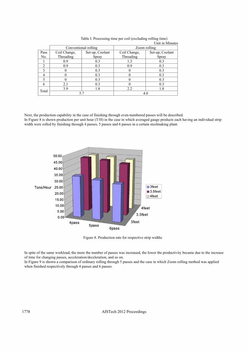
Table I. Processing time per coil (excluding rolling time) Unit in Minutes
Conventional rolling Zoom rolling Pass No.
Coil Change, Threading
Set-up, Coolant Spray
Coil Change, Threading
Set-up, Coolant Spray
1 0.9 0.3 1.3 0.3 2 0.9 0.3 0.9 0.33 0 0.3 0 0.34 0 0.3 0 0.35 0 0.3 0 0.36 2.1 0.3 0 0.3
Total 3.9 1.8 2.2 1.8 5.7 4.0
Next, the production capability in the case of finishing through even-numbered passes will be described. In Figure 8 is shown production per unit hour (T/H) in the case in which averaged gauge products each having an individual stripwidth were rolled by finishing through 4 passes, 5 passes and 6 passes in a certain steelmaking plant.
Figure 8. Production rate for respective strip widths
In spite of the same workload, the more the number of passes was increased, the lower the productivity became due to the increase of time for changing passes, acceleration/deceleration, and so on. In Figure 9 is shown a comparison of ordinary rolling through 5 passes and the case in which Zoom rolling method was applied when finished respectively through 4 passes and 6 passes.
AISTech 2012 Proceedings1778
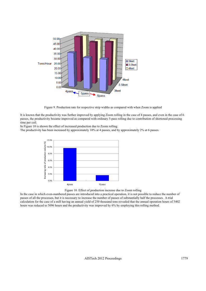
Figure 9. Production rate for respective strip widths as compared with when Zoom is applied It is known that the productivity was further improved by applying Zoom rolling in the case of 4 passes, and even in the case of 6 passes, the productivity became improved as compared with ordinary 5-pass rolling due to contribution of shortened processing time per coil. In Figure 10 is shown the effect of increased production due to Zoom rolling. The productivity has been increased by approximately 10% at 4 passes, and by approximately 2% at 6 passes.
Figure 10. Effect of production increase due to Zoom rolling In the case in which even-numbered passes are introduced into a practical operation, it is not possible to reduce the number of passes of all the processes, but it is necessary to increase the number of passes of substantially half the processes. A trial calculation for the case of a mill having an annual yield of 250 thousand tons revealed that the annual operation hours of 5402 hours was reduced to 5096 hours and the productivity was improved by 6% by employing this rolling method.
AISTech 2012 Proceedings 1779
REFFERENCES OF Zoom-MillTM
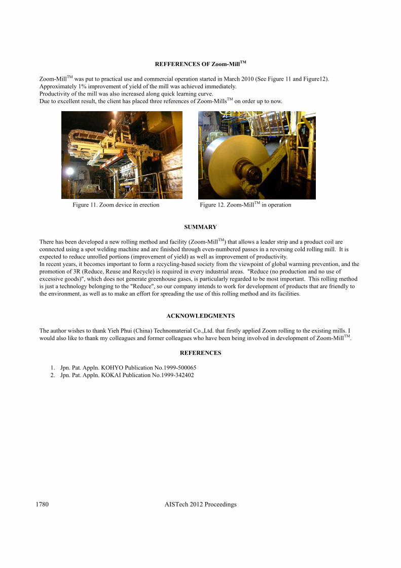
Zoom-MillTM was put to practical use and commercial operation started in March 2010 (See Figure 11 and Figure12). Approximately 1% improvement of yield of the mill was achieved immediately. Productivity of the mill was also increased along quick learning curve. Due to excellent result, the client has placed three references of Zoom-MillsTM on order up to now.
Figure 11. Zoom device in erection Figure 12. Zoom-MillTM in operation
SUMMARY
There has been developed a new rolling method and facility (Zoom-MillTM) that allows a leader strip and a product coil are connected using a spot welding machine and are finished through even-numbered passes in a reversing cold rolling mill. It is expected to reduce unrolled portions (improvement of yield) as well as improvement of productivity. In recent years, it becomes important to form a recycling-based society from the viewpoint of global warming prevention, and the promotion of 3R (Reduce, Reuse and Recycle) is required in every industrial areas. "Reduce (no production and no use of excessive goods)", which does not generate greenhouse gases, is particularly regarded to be most important. This rolling method is just a technology belonging to the "Reduce", so our company intends to work for development of products that are friendly to the environment, as well as to make an effort for spreading the use of this rolling method and its facilities.
ACKNOWLEDGMENTS
The author wishes to thank Yieh Phui (China) Technomaterial Co.,Ltd. that firstly applied Zoom rolling to the existing mills. I would also like to thank my colleagues and former colleagues who have been being involved in development of Zoom-MillTM.
REFERENCES
1. Jpn. Pat. Appln. KOHYO Publication No.1999-500065 2. Jpn. Pat. Appln. KOKAI Publication No.1999-342402
AISTech 2012 Proceedings1780