Embed Size (px)
Citation preview
Higher Technological Institute Mechanical Engineering Department
A Report on
Industrial Training ( Volkswagen service center )
Submitted by :
Name : Mustafa Amin Mohamed Mahfouze I.D : 20121441
Course code : ITR 102
Supervised By :
DR : Iman Ibrahim
August 2015
1 | P a g e
Acknowledge
Special tahnks to :
DR Iman who subervised our training along this course
All doctors and engineering who provided to us a lot information in this field
All tecnicns and engineering at the center specialy ENG: Ahmed sheriff El-znaty
2 | P a g e
Abstract
This report is going to handle whit service which Volkis service center specially Oboor
branch presented it and How they try to fix the problem at no time with very high quality
This services consists of main components like : Mechanical service , after buying services ,
body and paint service and others whish handle it at this report
3 | P a g e

List of content :
ContentsCHPTER ( 1 )......................................................................................................................................................................8
Introduction to Volkswagen company..............................................................................................................................8
Company History..........................................................................................................................................................8
Main Models :.............................................................................................................................................................10
Component of car.......................................................................................................................................................11
Mechanicaly parts :....................................................................................................................................................12
Motor.....................................................................................................................................................................12
A / crank shat..........................................................................................................................................................12
B / cams shaft ......................................................................................14
c/ Fly wheel............................................................................................................................................................16
D / piston................................................................................................................................................................17
E/ connection rod ( B.L)..........................................................................................................................................18
Volkes maintenance types :........................................................................................................................................19
1 – mechanically maintenance..............................................................................................................................19
2 – Body and painting maintenance.......................................................................................................................19
3 – after buying service...........................................................................................................................................19
4- genral service.....................................................................................................................................................19
CHAPTER ( 2 )..................................................................................................................................................................20
Mechanically Maintenance............................................................................................................................................20
Introduction :..............................................................................................................................................................20
2 – detecting the problem..........................................................................................................................................22
3 – fixation steps........................................................................................................................................................22
A ) Gear box fixiation..............................................................................................................................................23
B ) full fixation........................................................................................................................................................25
chapter ( 3 )....................................................................................................................................................................28
Body And Painting..........................................................................................................................................................28
4 | P a g e
Introduction :..............................................................................................................................................................28
Fixation step :.............................................................................................................................................................28
3 - Painting..................................................................................................................................................................31
CHAPTER ( 5 )..................................................................................................................................................................34
SERVICES AFTER BUYING................................................................................................................................................34
1 – intrudction :..........................................................................................................................................................34
2 – types of this maintenance....................................................................................................................................34
A – oil change :.......................................................................................................................................................34
CHAPTER ( 6 )..................................................................................................................................................................38
Cautchouc service..........................................................................................................................................................38
1 – intrudction............................................................................................................................................................38
Basic Alignment Procedures.......................................................................................................................................38
Attach the Targets/Pods.............................................................................................................................................39
For outside rim mounting:..........................................................................................................................................39
Balance procedure......................................................................................................................................................41
5 | P a g e
Table of figure
Figure 1: compare between volks logo...................................................................................11Figure 2: cranck shat...............................................................................................................15Figure 3: cams shaft................................................................................................................17Figure 4: fly wheel...................................................................................................................19Figure 5 :.................................................................................................................................20Figure 6 : connection rod (B.L)................................................................................................21Figure 7 : pro.diagnosis system..............................................................................................23Figure 8 : pro diagosis system 2..............................................................................................24Figure 9 : jop model................................................................................................................25Figure 10 : gear box................................................................................................................26Figure 11 : gear box jack.........................................................................................................27Figure 12 : bored control unit.................................................................................................28Figure 13 : engine sling...........................................................................................................29Figure 14 : instal engin sling...................................................................................................29Figure 15 : displacement motor..............................................................................................29Figure 16 :dameged piston from motor..................................................................................29Figure 17 : processing of cleaning motor................................................................................30Figure 18 : new piston installtion............................................................................................31Figure 19 : torqe hand............................................................................................................31Figure 20 : model of analogize................................................................................................33Figure 21 : car welding...........................................................................................................33Figure 22 : fixation hydro device.............................................................................................34Figure 23 : types of gage........................................................................................................35Figure 24 : softing of car.........................................................................................................35Figure 25 : embrey car body...................................................................................................36Figure 26 : painting furnans....................................................................................................36Figure 27 :coloring codin system............................................................................................37Figure 28 : types of painting...................................................................................................37Figure 29 : covering the car process.......................................................................................38
6 | P a g e
Figure 30 : painting car proess................................................................................................38Figure 31 : car lever................................................................................................................40Figure 32 : dissemble the togge of oil.....................................................................................40Figure 33 : empting oil progress.............................................................................................41Figure 34 : removing old filter oil process...............................................................................42Figure 35 : putting new filtter process....................................................................................42Figure 36 : adiing oil...............................................................................................................43Figure 37 : car lever................................................................................................................44Figure 38 : the pods are atteched to the wheel......................................................................46Figure 39 : balancing machine................................................................................................47Figure 40 : fixation the tire on the device...............................................................................47Figure 41 : sensor edge angle.................................................................................................48
7 | P a g e
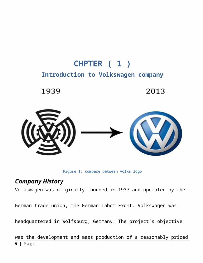
CHPTER ( 1 )Introduction to Volkswagen company
Figure 1: compare between volks logo
Company HistoryVolkswagen was originally founded in 1937 and operated by the German trade union, the
German Labor Front. Volkswagen was headquartered in Wolfsburg, Germany. The project’s
objective was the development and mass production of a reasonably priced yet still speedy
automobile that could sell for less than 1,000 Reich marks (approximately $140 at the time).
Known as Volkswagenwerk, or "The People's Car Company" at the time, to provide the
8 | P a g e
design for this "people's car," the German Labor Front called in the Austrian automotive
engineer Ferdinand Porsche.
However, shortly after the KdF (Kraft-durch-Freude)-Wagen ("Strength-Through-Joy" car)
was presented for the first time at the Berlin Motor Show in 1939, World War II began, and
Volkswagen ceased production. After the war ended, with the plant in ruins, the Allies
would make Volkswagen the center of their attempts to revive the German auto industry. In
1959, the advertising agency Doyle Dane Bernbach launched an innovative campaign,
naming the car the "Beetle" and turning its miniature size as a distinct advantage to
consumers. Over the next several years, Volkswagen became the top-selling auto import in
the United States. In 1960, the German government vended 60 percent of Volkswagen's
stock to the German public, successfully denationalizing it. Twelve years later, the Beetle
bettered the longstanding worldwide manufacturing record of 15 million automobiles. With
the Beetle's design comparatively unchanged since 1935, sales grew lazy in the early 1970s.
Volkswagen reboundedwith the introduction of sportier models such as the Rabbit and
later, the Golf. In 1998, the company began selling the vastly advertised "New Beetle"
although still continuing production of its predecessor. After nearly 70 years and more than
9 | P a g e
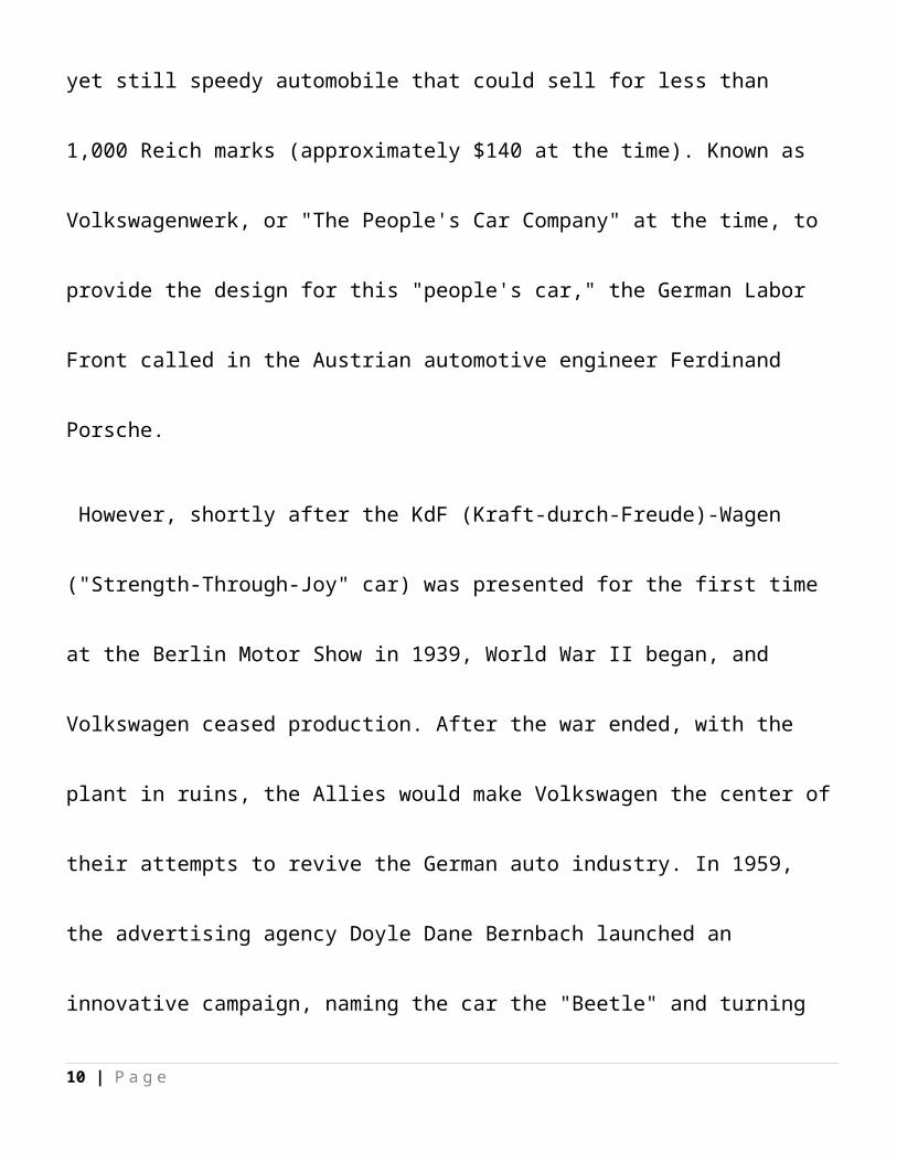
21 million units produced, the last original Beetle rolled off the line in Puebla,Mexico, on
July 30, 2003.
Main Models :Germany: Wolfsburg (Golf, Tiguan, Touran), Emden (Passat), Zwickau (Golf, Passat), Dresden
(Phaeton).
Belgium: Brussels (Polo, Golf)
Spain: Pamplona (Polo)
Portugal: Palmela (Eos, Sharan)
Slovakia: Bratislava (Up, Polo, Touareg)
Mexico: Puebla (Jetta, New Beetle)
Brazil: Anchieta (Gol, Polo, Fox), Curitiba (Golf, Fox)
South Africa: Uitenhage (Polo, Golf, Jetta)
10 | P a g e
Component of car 1 - Mechanically parts
2 – body parts
3 – interment parts
11 | P a g e

Mechanicaly parts :
Motor This is the most important part in the car due to it is responsible of move the car but it
consist of many parts :
A / crank shat
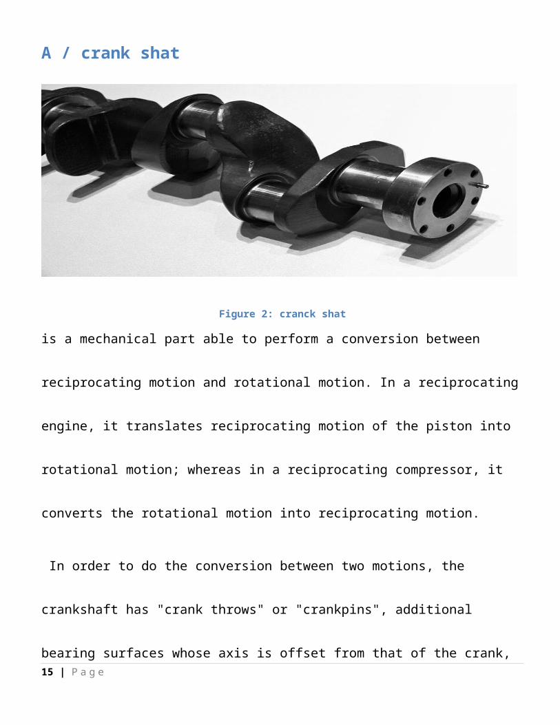
Figure 2: cranck shat
is a mechanical part able to perform a conversion between reciprocating motion and
rotational motion. In a reciprocating engine, it translates reciprocating motion of the piston
12 | P a g e
into rotational motion; whereas in a reciprocating compressor, it converts the rotational
motion into reciprocating motion.
In order to do the conversion between two motions, the crankshaft has "crank throws" or
"crankpins", additional bearing surfaces whose axis is offset from that of the crank, to which
the "big ends" of the connecting rods from each cylinder attach.
It is typically connected to a flywheel to reduce the pulsation characteristic of the four-
stroke cycle, and sometimes a torsional or vibrational damper at the opposite end, to
reduce the torsional vibrations often caused along the length of the crankshaft by the
cylinders farthest from the output end acting on the torsional elasticity of the metal.
13 | P a g e
B / cams shaft
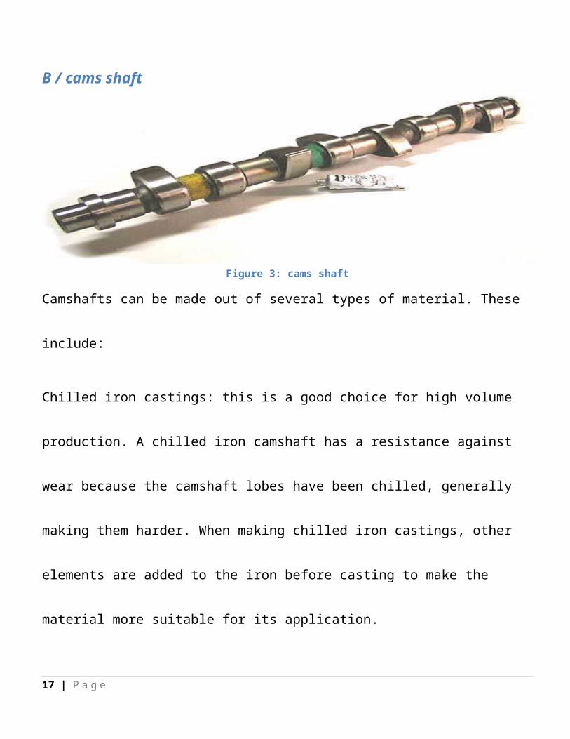
Figure 3: cams shaft
Camshafts can be made out of several types of material. These include:
Chilled iron castings: this is a good choice for high volume production. A chilled iron
camshaft has a resistance against wear because the camshaft lobes have been chilled,
generally making them harder. When making chilled iron castings, other elements are added
to the iron before casting to make the material more suitable for its application.
Billet Steel: When a high quality camshaft is required, engine builders and camshaft
manufacturers choose to make the camshaft from steel billet. This method is also used for
low volume production. This is a much more time consuming process, and is generally more
expensive than other methods. However the finished product is far superior.
14 | P a g e
When making the camshaft, CNC lathes, CNC milling machines and CNC camshaft grinders
will be used. Different types of steel bar can be used, one example being EN40b. When
manufacturing a camshaft from EN40b, the camshaft will also be heat treated via gas
nitriding, which changes the micro-structure of the material. It gives a surface hardness of
55-60 HRC. These types of camshafts can be used in high-performance engines.
15 | P a g e
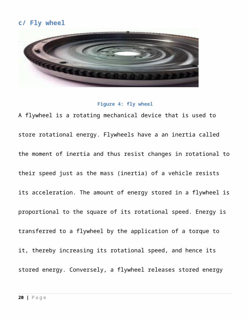
c/ Fly wheel
Figure 4: fly wheel
A flywheel is a rotating mechanical device that is used to store rotational energy. Flywheels
have a an inertia called the moment of inertia and thus resist changes in rotational to their
speed just as the mass (inertia) of a vehicle resists its acceleration. The amount of energy
stored in a flywheel is proportional to the square of its rotational speed. Energy is
transferred to a flywheel by the application of a torque to it, thereby increasing its
rotational speed, and hence its stored energy. Conversely, a flywheel releases stored energy
by applying torque to a mechanical load, thereby decreasing the flywheel's rotational
speed.c/ fly wheel
16 | P a g e
D / piston
Figure 5 : piston
is a component of reciprocating engines, reciprocating pumps, gas compressors and pneumatic cylinders, among other similar mechanisms. It is the moving component that is contained by a cylinder and is made gas-tight by piston rings. In an engine, its purpose is to transfer force from expanding gas in the cylinder to the crankshaft via a piston rod and/or connecting rod. In a pump, the function is reversed and force is transferred from the crankshaft to the piston for the purpose of compressing or ejecting the fluid in the cylinder. In some engines, the piston also acts as a valve by covering and uncovering ports in the cylinder wall.
17 | P a g e
E/ connection rod ( B.L)
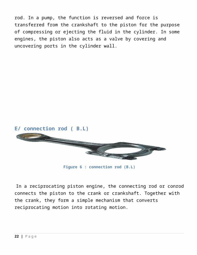
Figure 6 : connection rod (B.L)
In a reciprocating piston engine, the connecting rod or conrod connects the piston to the crank or crankshaft. Together with the crank, they form a simple mechanism that converts reciprocating motion into rotating motion.
Connecting rods may also convert rotating motion into reciprocating motion. Historically, before the development of engines, they were first used in this way.
As a connecting rod is rigid, it may transmit either a push or a pull and so the rod may rotate the crank through both halves of a revolution, i.e. piston pushing and piston pulling. Earlier mechanisms, such as chains, could only pull. In a few two-stroke engines, the connecting rod is only required to push.
18 | P a g e

Volkes maintenance types :
1 – mechanically maintenance This type presented to us the mechanical problem at motor
or another part of car and the wright way to fix it
2 – Body and painting maintenance It represent the body of cars and problem of body due to
accident and crushes and how to back it to original shape
3 – after buying service This type of service represented changing oil and oils filter and
other that we handle it with details later
4- genral service Like caoutchouc service and angle fixation and stabilization
19 | P a g e
CHAPTER ( 2 )
Mechanically Maintenance
Introduction :At this chapter we detail exposed to the mechanically parts and mainly problem of it
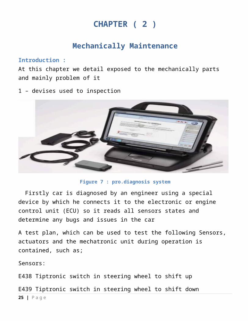
1 – devises used to inspection
Figure 7 : pro.diagnosis system
Firstly car is diagnosed by an engineer using a special device by which he connects it to the electronic or engine control unit (ECU) so it reads all sensors states and determine any bugs and issues in the car
A test plan, which can be used to test the following Sensors, actuators and the mechatronic unit during operation is contained, such as;
Sensors:
E438 Tiptronic switch in steering wheel to shift up
E439 Tiptronic switch in steering wheel to shift down
G182 Gearbox input speed sender
G270 Gearbox hydraulic pressure sender
20 | P a g e
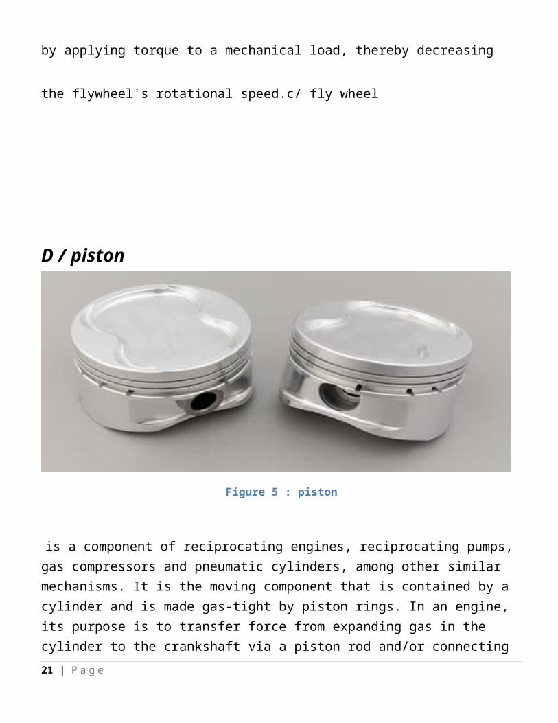
Figure 8 : pro diagosis system 2
This devises are used to established the car after maintenance and another mainly purpose to detect the problems of cars
21 | P a g e
2 – detecting the problem After inspection and firstly look on the car it takes which called jop and transport to the engineer on charge who presented it to the suitable technicians
Figure 9 : jop model
3 – fixation stepsFirstly tecnicas start to take the jop and see whts is the part which has the problem and get to ix it
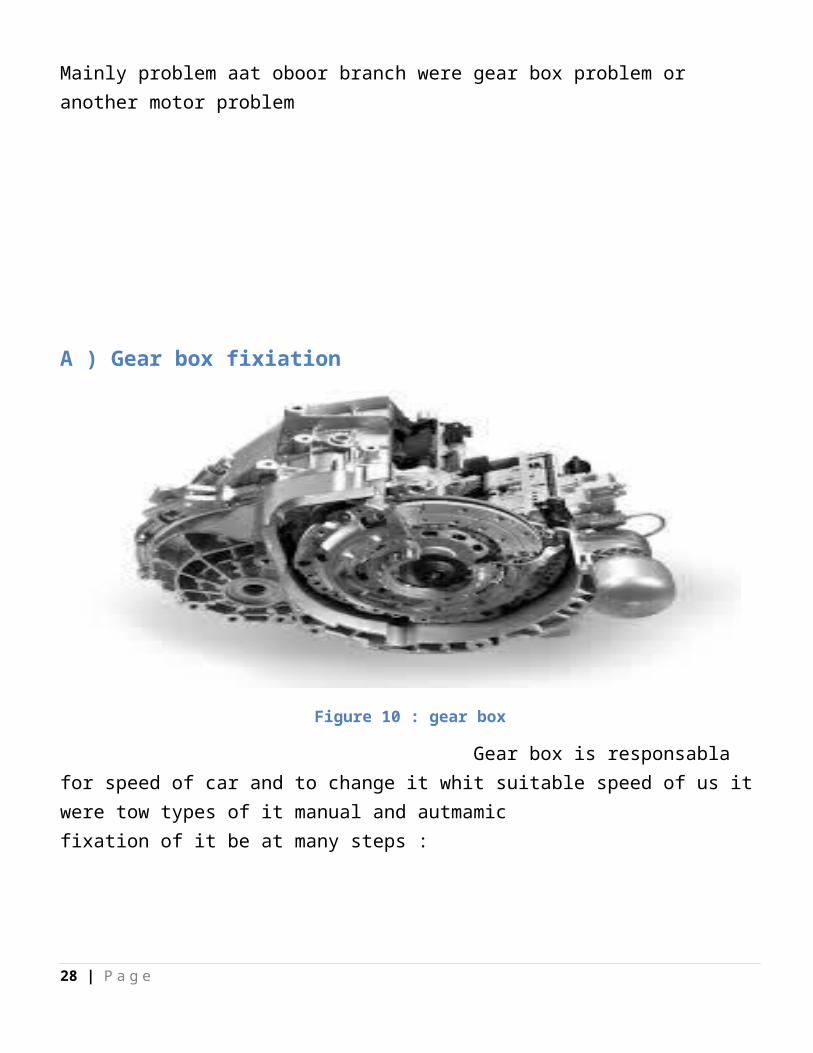
Mainly problem aat oboor branch were gear box problem or another motor problem
22 | P a g e
A ) Gear box fixiation
Figure 10 : gear box
Gear box is responsabla for speed of car and to change it whit suitable speed of us it were tow types of it manual and autmamic fixation of it be at many steps :
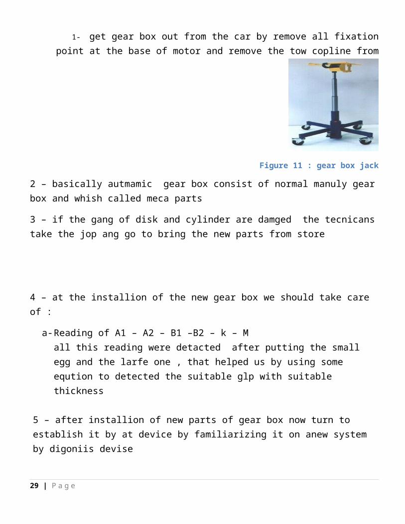
1- get gear box out from the car by remove all fixation point at the base of motor and
remove the tow copline from
Figure 11 : gear box jack
2 – basically autmamic gear box consist of normal manuly gear box and whish called meca parts
3 – if the gang of disk and cylinder are damged the tecnicans take the jop ang go to bring the new parts from store
23 | P a g e
4 – at the installion of the new gear box we should take care of :
a- Reading of A1 – A2 – B1 –B2 – k – Mall this reading were detacted after putting the small egg and the larfe one , that helped us by using some eqution to detected the suitable glp with suitable thickness
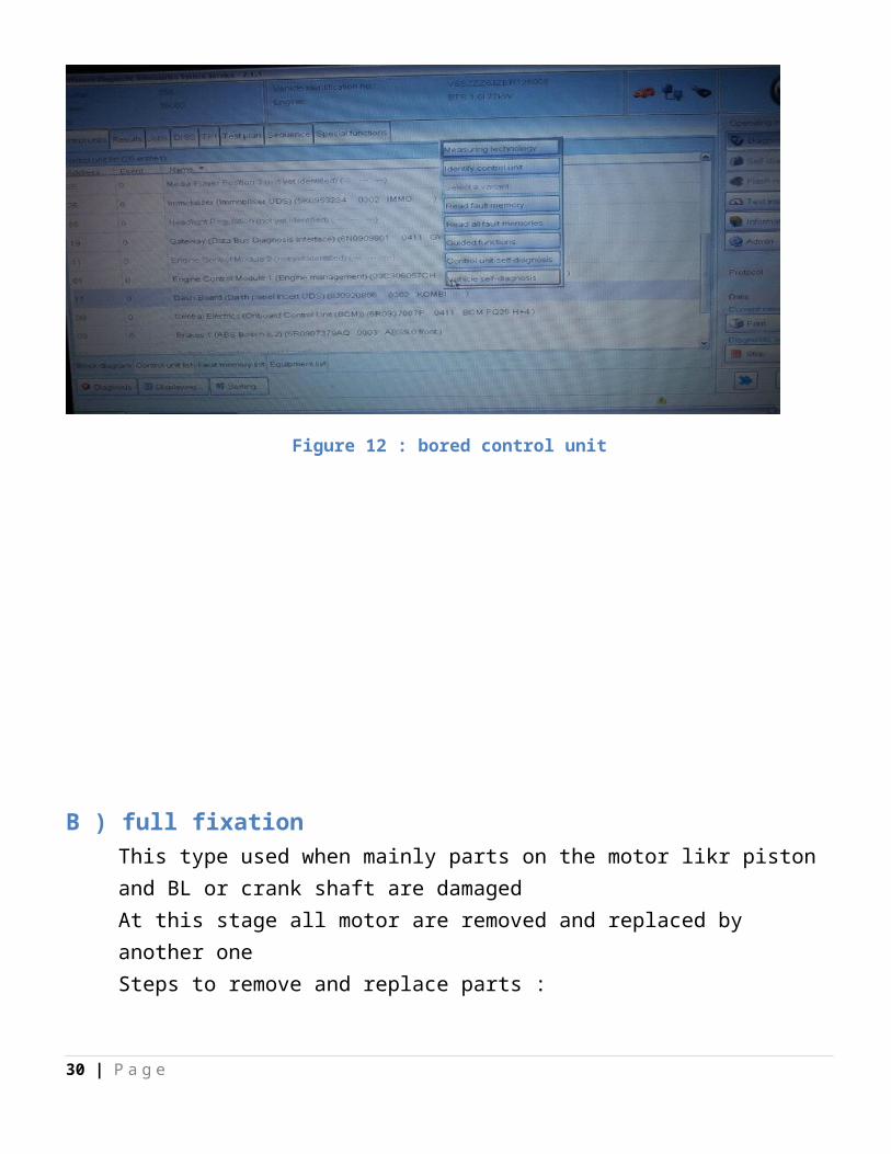
5 – after installion of new parts of gear box now turn to establish it by at device by familiarizing it on anew system by digoniis devise
Figure 12 : bored control unit
24 | P a g e
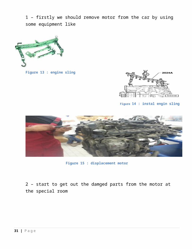
B ) full fixationThis type used when mainly parts on the motor likr piston and BL or crank shaft are damaged At this stage all motor are removed and replaced by another oneSteps to remove and replace parts :1 – firstly we should remove motor from the car by using some equipment like
Figure 14 : instal engin sling
Figure 15 : displacement motor
2 – start to get out the damged parts from the motor at the special room
25 | P a g e
Figure 13 : engine sling
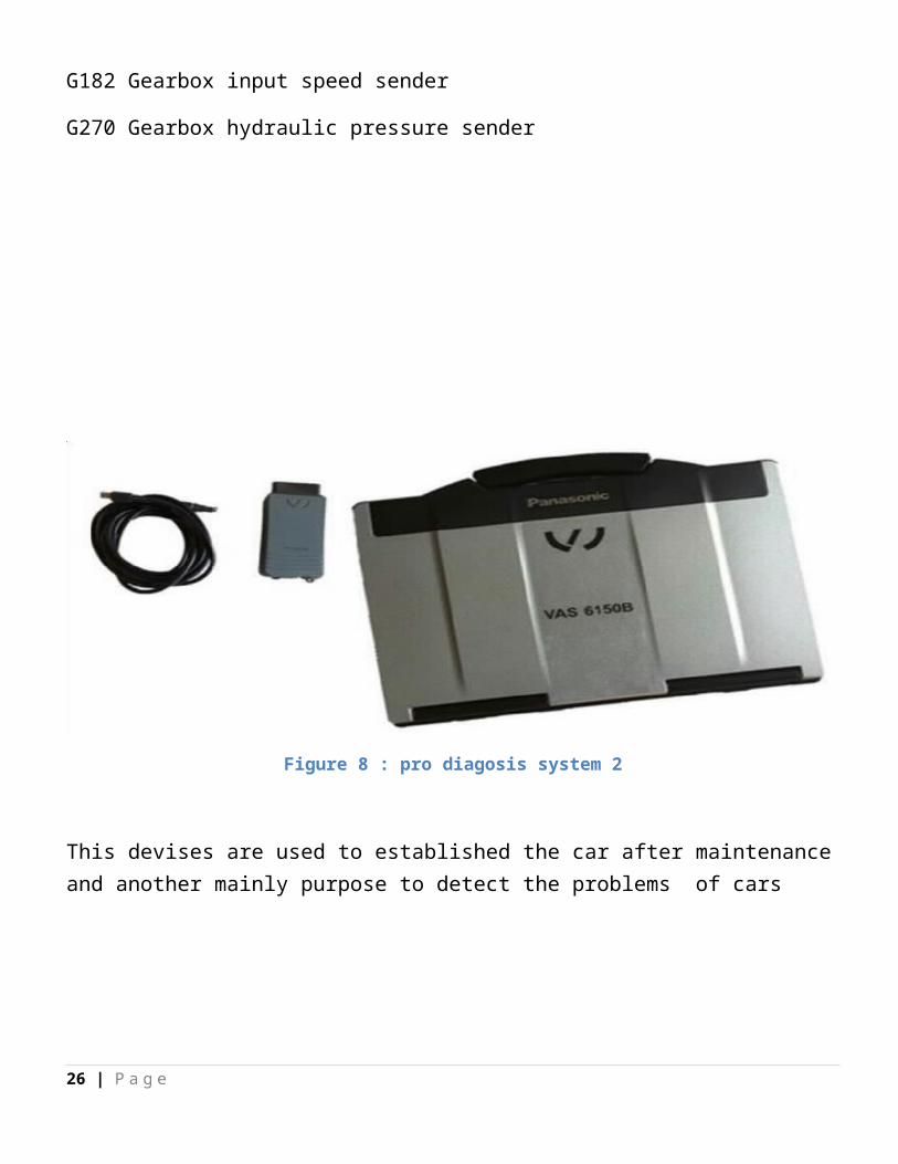
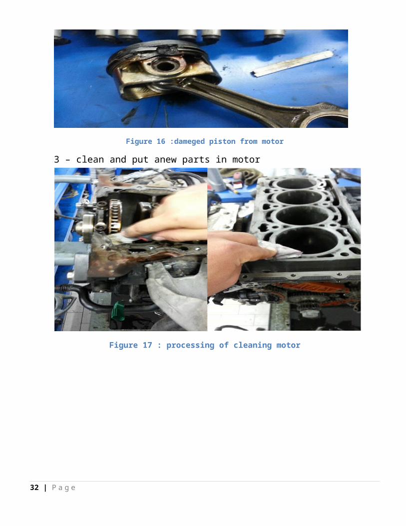
Figure 16 :dameged piston from motor
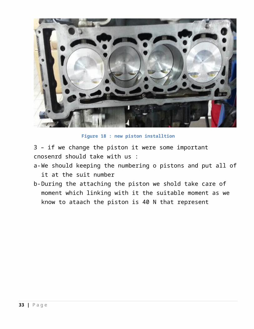
3 – clean and put anew parts in motor
Figure 17 : processing of cleaning motor
26 | P a g e
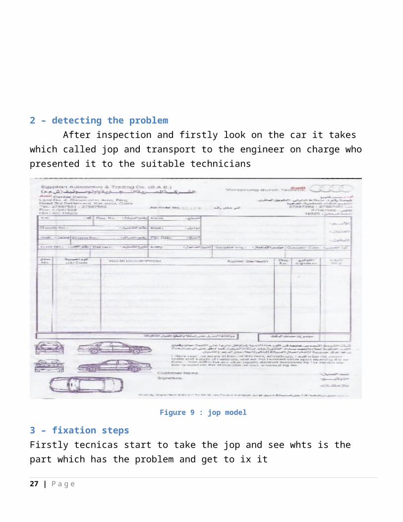
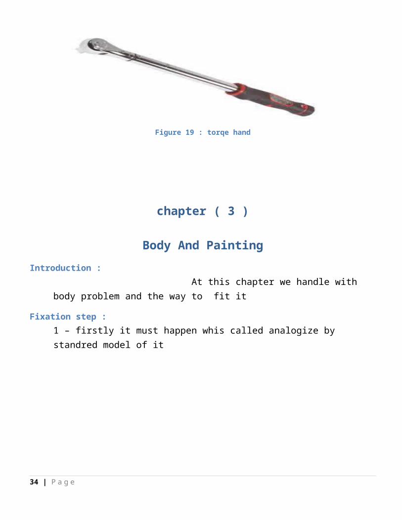
Figure 18 : new piston installtion
3 – if we change the piston it were some important cnosenrd should take with us :a- We should keeping the numbering o pistons and put all of it at the suit number b- During the attaching the piston we shold take care of moment which linking with it
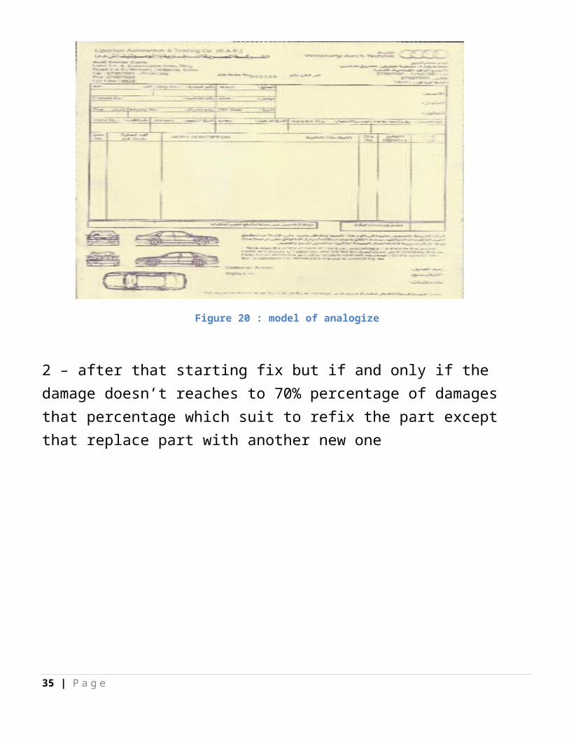
the suitable moment as we know to ataach the piston is 40 N that represent
Figure 19 : torqe hand
27 | P a g e
chapter ( 3 )
Body And Painting
Introduction : At this chapter we handle with body problem and the way to fit it
Fixation step :1 – firstly it must happen whis called analogize by standred model of it
Figure 20 : model of analogize
2 – after that starting fix but if and only if the damage doesn’t reaches to 70% percentage of damages that percentage which suit to refix the part except that replace part with another new one
28 | P a g e
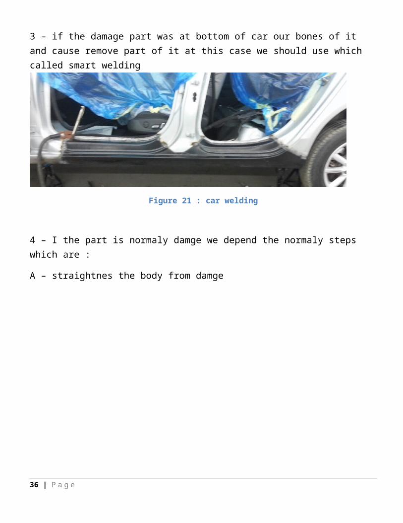
3 – if the damage part was at bottom of car our bones of it and cause remove part of it at this case we should use which called smart welding
Figure 21 : car welding
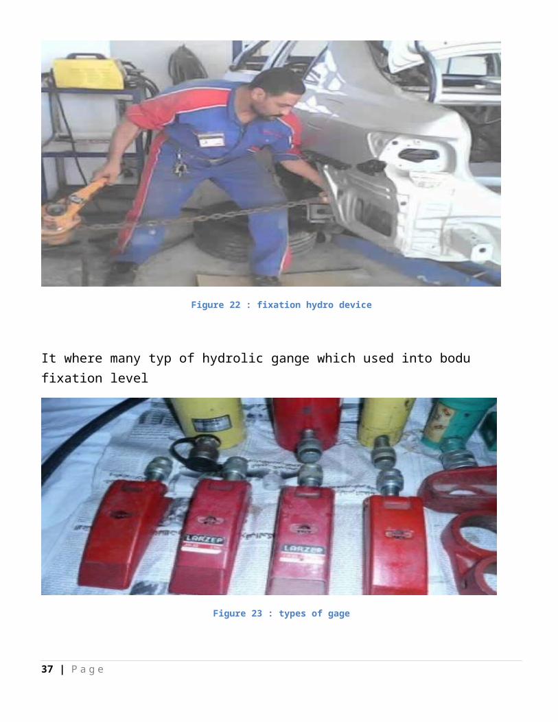
4 – I the part is normaly damge we depend the normaly steps which are :
A – straightnes the body from damge
Figure 22 : fixation hydro device
29 | P a g e
It where many typ of hydrolic gange which used into bodu fixation level
Figure 23 : types of gage
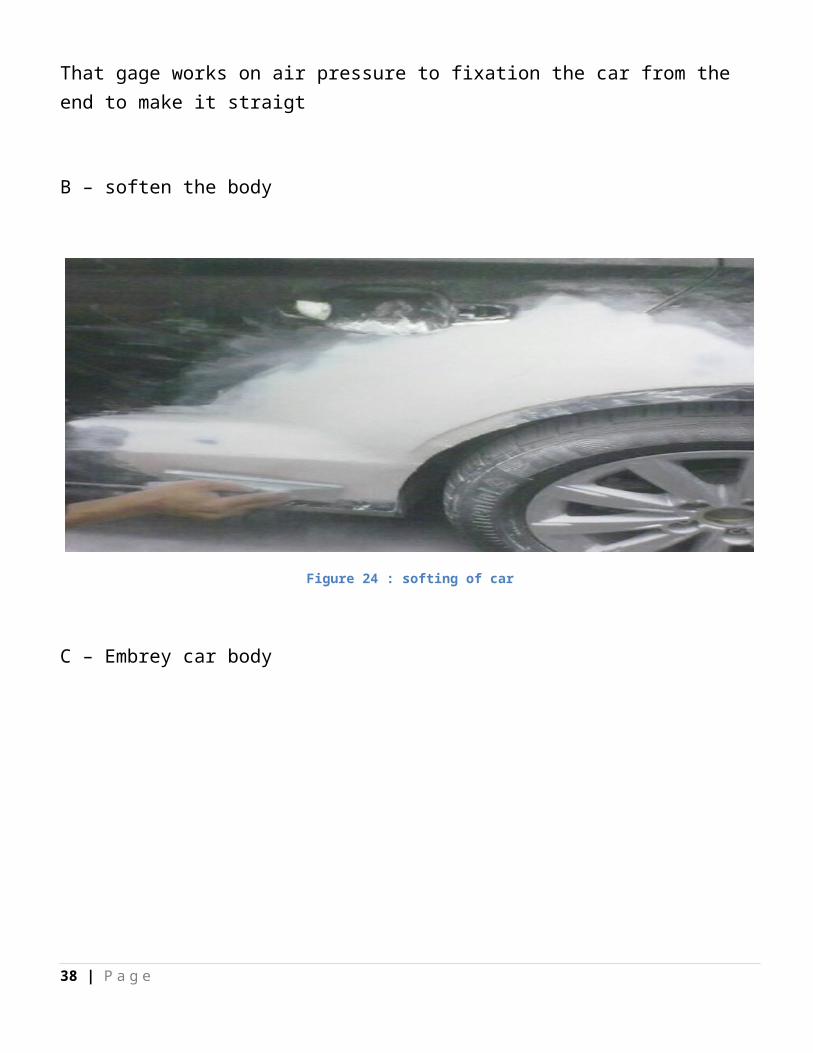
That gage works on air pressure to fixation the car from the end to make it straigt
B – soften the body
Figure 24 : softing of car
30 | P a g e
C – Embrey car body
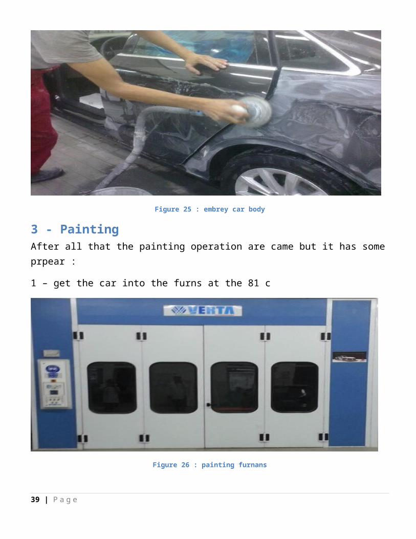
Figure 25 : embrey car body
3 - Painting After all that the painting operation are came but it has some prpear :
1 – get the car into the furns at the 81 c
Figure 26 : painting furnans
31 | P a g e
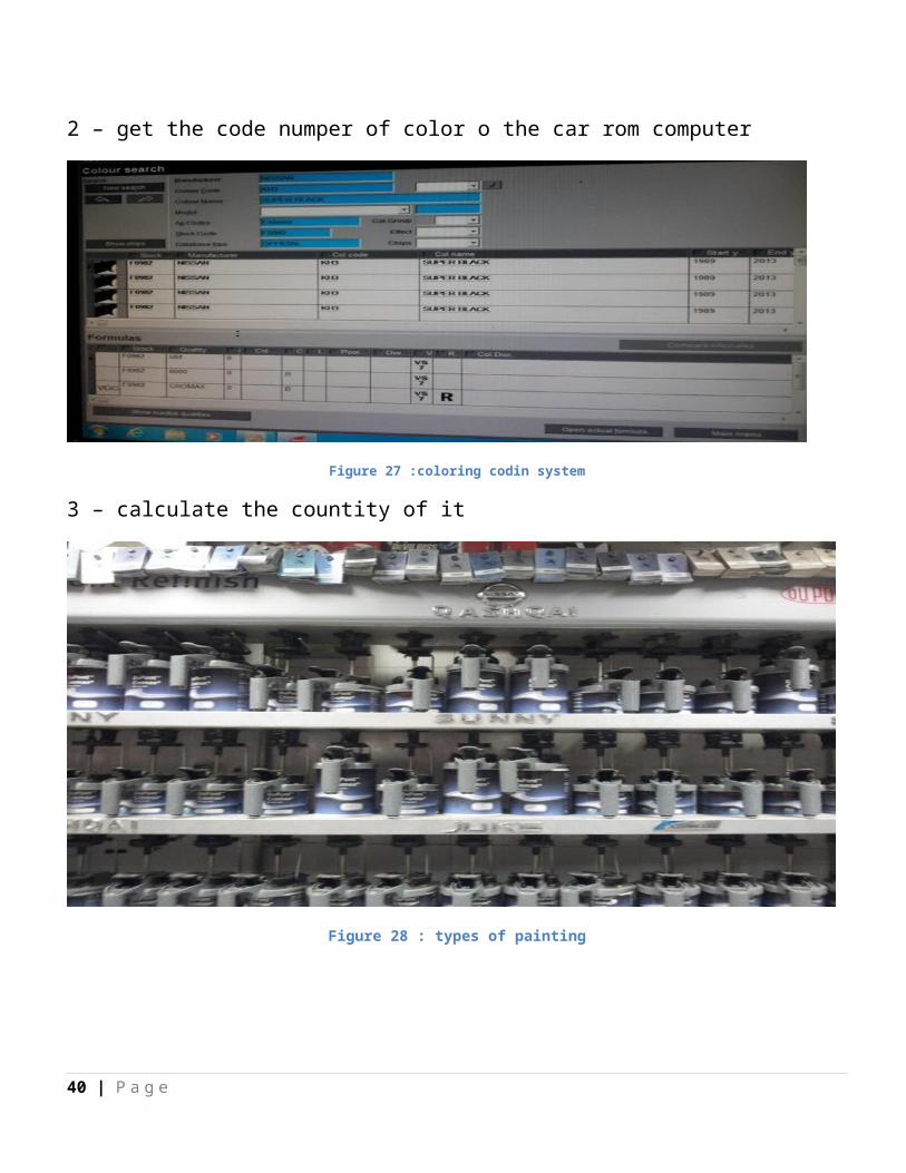
2 – get the code numper of color o the car rom computer
Figure 27 :coloring codin system
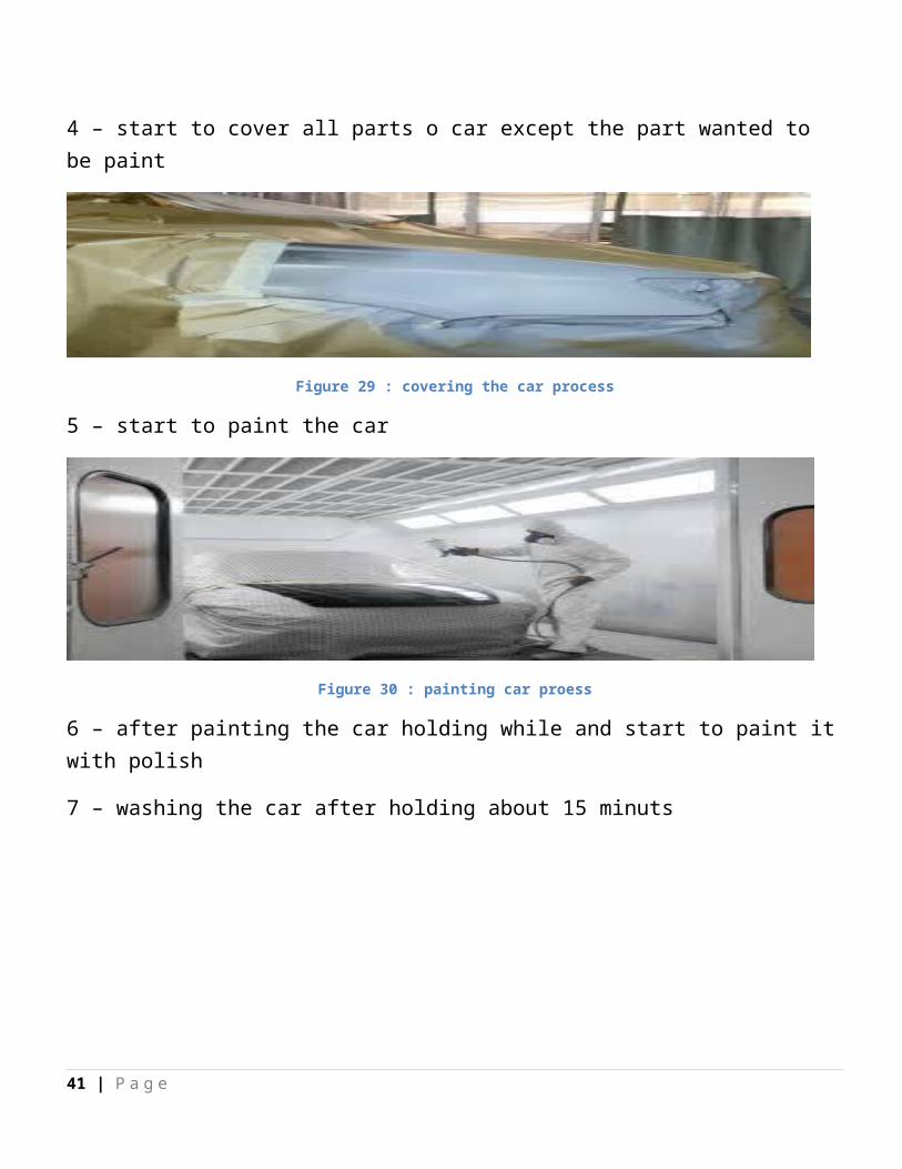
3 – calculate the countity of it
Figure 28 : types of painting
32 | P a g e
4 – start to cover all parts o car except the part wanted to be paint
Figure 29 : covering the car process
5 – start to paint the car
Figure 30 : painting car proess
6 – after painting the car holding while and start to paint it with polish
7 – washing the car after holding about 15 minuts
33 | P a g e
CHAPTER ( 5 )
SERVICES AFTER BUYING
1 – intrudction : AT THIS PART WE HANDLE WITH periodic maintenance that th client should do after excating time
2 – types of this maintenance
A – oil change :
It recommented to change oil after 10,000 KM to save the motor rom damge
Steps of oil change :
1 – first get the car on the lever
Figure 31 : car lever
34 | P a g e
2 – dissemble the toggle of oil
Figure 32 : dissemble the togge of oil
3 – hold on to empty all dirty oil rom the motor
Figure 33 : empting oil progress
4 – bind the toggle of oil finaly
5 – get the car down
35 | P a g e
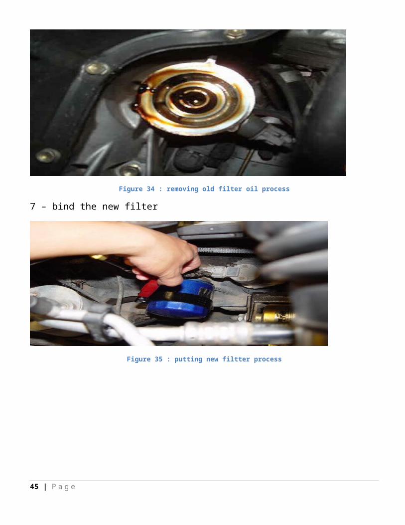
6 – desimmpe the filtter of oil
Figure 34 : removing old filter oil process
7 – bind the new filter
Figure 35 : putting new filtter process
36 | P a g e
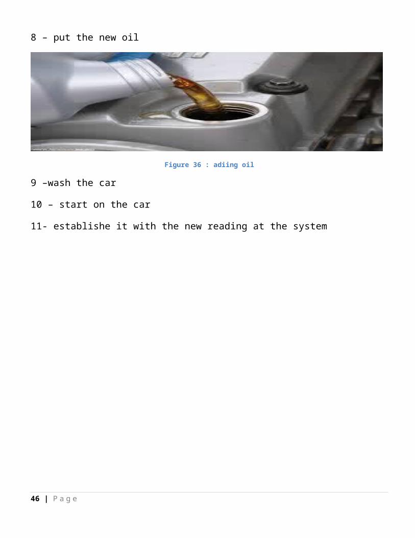
8 – put the new oil
Figure 36 : adiing oil
9 –wash the car
10 – start on the car
11- establishe it with the new reading at the system
37 | P a g e
CHAPTER ( 6 )
Cautchouc service
1 – intrudction At this part we see the problem of tires from pressure of it to stability
Figure 37 : car lever
Basic Alignment ProceduresPositioning the Vehicle on the LiftProper vehicle positioning on the alignment lift is an important step for safety and accuracy.
1 .Make sure the front turntable and rear slip plate locking pins are in place.NOTE: Steps 2 - 5 are recommended to make sure the front tires are placed in the center of the turntables.NOTE: If an optional drive-on camera aid is available proceed to step 2, if not available skip to step 3.
2 .From the Home Screen click on the “Rack Drive-on Aid” icon located on the upper tool-bar. View the screen while positioning the vehicle.
3 .Drive the vehicle onto the alignment lift and stop just before the turntables. Take care to insure the vehicle is centered on the runways.
38 | P a g e
4 .Place the vehicle in park (or in gear on a standard transmission), turn the ignition off, and set the parking brake on. Place wheel chocks behind the tires to prevent rolling.Failure to use the wheel chocks can allow the vehicle to roll off the rack/lift.
5 .Position the turntables as needed to insure the tires will be centered.6 .Drive the vehicle forward onto the center of the turntables.
Alternative Method: This method extends turntable life due to relief of load and stresses encountered when the brakes are applied (or acceleration on a FWD vehicle).
7 .Place the vehicle in neutral, release the parking brake, and pull or push the vehicle forward onto the turntables. Reposition the wheel chocks, place the vehicle in park, and reapply the parking brake.To avoid personal injury or damage to property, follow the rack/lift manufacturer’s operating and safety procedures.
8 .Raise the alignment lift, then lower the lift onto its mechanical stops.9 .Place the transmission in neutral and release the parking brake just before beginning the
Vehicle Positioning process.
Attach the Targets/PodsThe targets/pods are attached to the wheels using the wheel clamps. The targets go on the front wheels, the measuring pods on the rear.There are several methods of attachment depending on the wheel lip configuration. The integrated claws provide the versatility needed to grab virtually any wheel. The claws can be rotated to adjust for different wheel configurations.Claws may have sharp edges. To avoid personal injury, use caution when working with wheel clamps.The clamps should be installed in a straight-up vertical manner (knob at the top).Use the mounting method that provides the greatest security to keep the target from falling off the wheel. Most wheels can be grabbed from the outside-in by placing the claws between the bead of the tire and the outside edge of the rim. Others can be mounted on the inside of the rim such as with steel wheels.
For outside rim mounting:
1 .Extend the clamp to a size slightly larger than the rim by turning the knob.2 .Place the upper claws on the outside of the top of the rim. Push the claws in between the
tire bead and the rim. It may be necessary to “pop” the upper clamp bracket with the palm of your hand to seat well. Note that it is not necessary for the clamp to be mounted perfectly vertical on the wheel.
3 .Tighten the clamp by turning the knob clockwise until the lower claws engage the rim.
39 | P a g e
4 .Push the lower claws into place. Again, it may be necessary to pop them in further for security. Continue tightening the knob until secure.
5 .Test the security by pulling outwards on the clamp. If it comes off easily, reattach the clamp or select an alternative mounting method.
Figure 38 : the pods are atteched to the wheel
.Wheel balance machine
Figure 39 : balancing machine
40 | P a g e
Balance procedure
Install the tire on wheel balance machine
Figure 40 : fixation the tire on the device
Use sensor on the edge of tire to measure diameter of tire
41 | P a g e
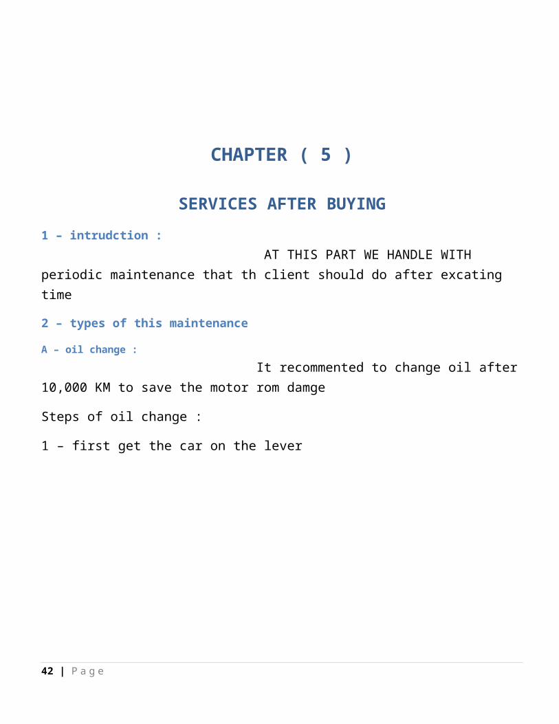
Figure 41 : sensor edge angle
Figure 42 : reading of device
get off the cover of the machine on the wheel to turn it
42 | P a g e
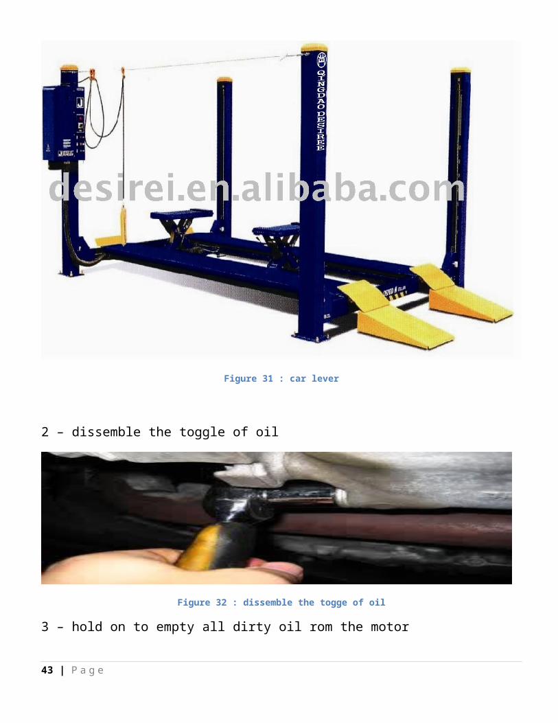
Figure 43 : the tire turn on machine
The machine determine the amount of Wight need to install and the correct place on tire edge
Figure 44 : instruction from device
check again the tire
43 | P a g e
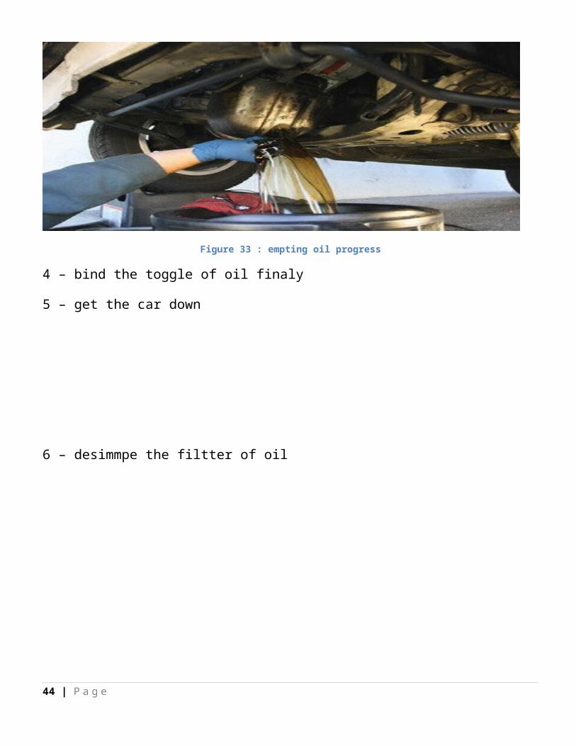
Figure 45 : checking the tire
Coclusion :
From all the past information we learn about how the car maintnenanse at the service center and the level which all type of maintenance take
44 | P a g e
Recommendation
It is recommended to increase the period of the course to achieve the max benefit and gain the experience which qualifies us to the work after graduate
45 | P a g e
References :
1- wikipedia 2- 2 – automotive reference3- Some of online website about car maintenance
46 | P a g e


![Introduction - interoperability.blob.core.windows.netMS-OFFDI]-160914.docx · Web view, by using Microsoft Word 2013, Microsoft Word 2010, Microsoft Office Word 2007, Microsoft](https://img.dokumen.tips/doc/110x75/5d51318488c993b0478b9899/introduction-ms-offdi-160914docx-web-view-by-using-microsoft-word-2013-microsoft.jpg)