Embed Size (px)
Citation preview

New Holland
TC35DA, TC40DA, TC45DAParts List & Mounting Instructions
Jodale • Perry
Printed: 2004/08
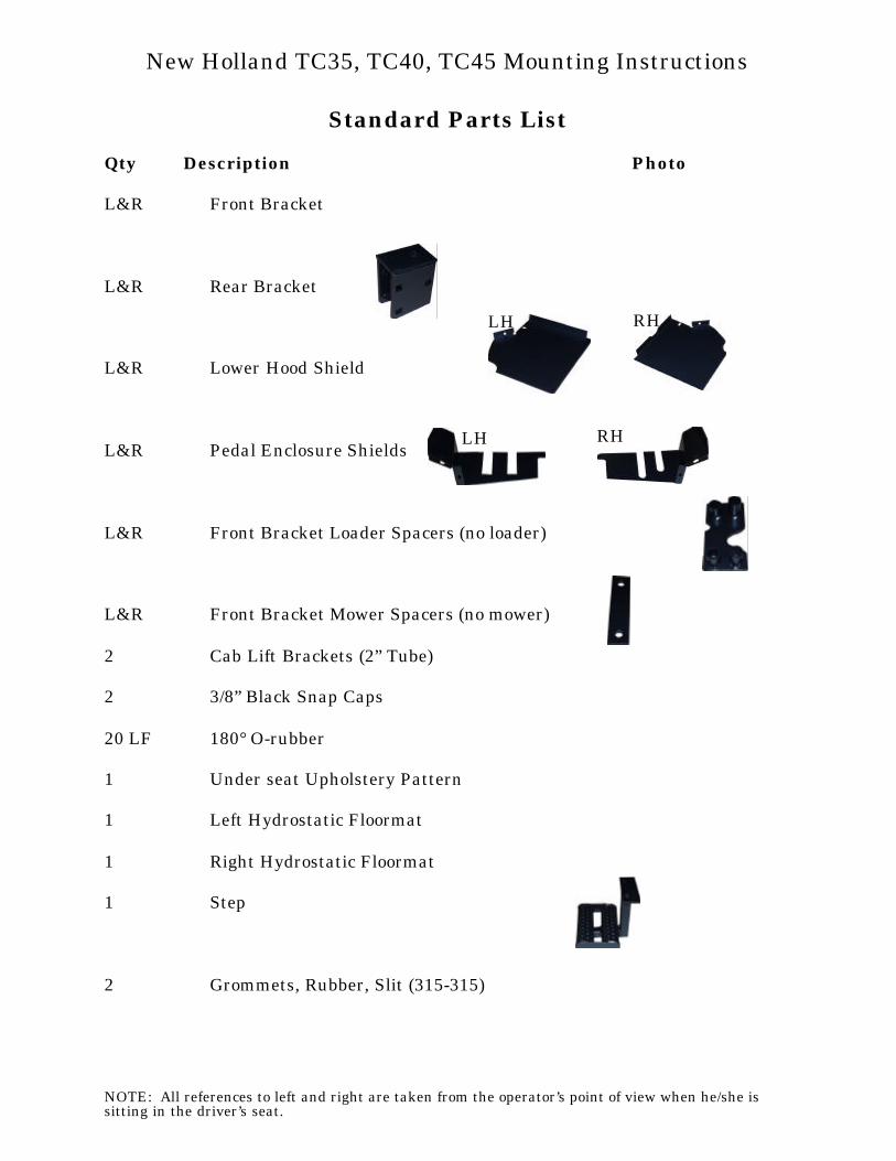
Standard Parts List
Qty Description Photo
L&R Front Bracket
L&R Rear Bracket
L&R Lower Hood Shield
L&R Pedal Enclosure Shields
L&R Front Bracket Loader Spacers (no loader)
L&R Front Bracket Mower Spacers (no mower)
2 Cab Lift Brackets (2” Tube)
2 3/8” Black Snap Caps
20 LF 180° O-rubber
1 Under seat Upholstery Pattern
1 Left Hydrostatic Floormat
1 Right Hydrostatic Floormat
1 Step
2 Grommets, Rubber, Slit (315-315)
NOTE: All references to left and right are taken from the operator’s point of view when he/she issitting in the driver’s seat.
New Holland TC35, TC40, TC45 Mounting Instructions
RH
LH
LH
RH
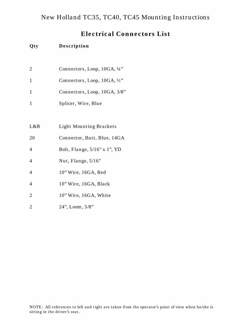
Electrical Connectors List
Qty Description
2 Connectors, Loop, 10GA, ¼”
1 Connectors, Loop, 10GA, ½”
1 Connectors, Loop, 10GA, 3/8”
1 Splicer, Wire, Blue
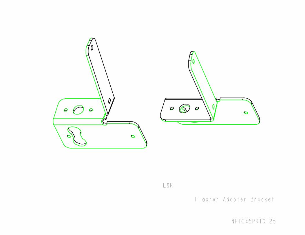
L&R Light Mounting Brackets
20 Connector, Butt, Blue, 14GA
4 Bolt, Flange, 5/16” x 1”, YD
4 Nut, Flange, 5/16”
4 10” Wire, 16GA, Red
4 10” Wire, 16GA, Black
2 10” Wire, 16GA, White
2 24”, Loom, 5/8”
NOTE: All references to left and right are taken from the operator’s point of view when he/she issitting in the driver’s seat.
New Holland TC35, TC40, TC45 Mounting Instructions
Standard Bolts List
Qty Description
6 Bolt, Carriage, 5/8”x 3 ½”, Grade 8, Yellow Dichrome
4 Bolt, Hex, 5/8” x 3”, Grade 8, Yellow Dichrome
8 Bolt, Hex, 16MM x 2.0 x 100MM, Grade 10.9, Yellow Dichrome
6 Nut, Hex, 5/8”, Grade 8, Yellow Dichrome
14 Washer, Lock, 5/8”
4 Washer, Flat, 5/8” x 2”, Yellow Dichrome
4 Washer, Rubber, 5/8” x 2 ½”
4 Isolator, Rubber, 5/8” x 2”
14 Nut, Flange, ¼”, Macro-black
14 Bolt, Flange, ¼” x ¾”, Yellow Dichrome
2 Nut, Flange, M8 x 1.25, Yellow Dichrome
2 Bolt, Flange, 3/8” x ¾”, Yellow Dichrome
4 Nut, Hex, Nylon-Locking, 5/8”, Grade 8, Yellow Dichrome
NOTE: All references to left and right are taken from the operator’s point of view when he/she issitting in the driver’s seat.
New Holland TC35, TC40, TC45 Mounting Instructions
Optional Parts ListsHeater Option (if equipped)
Qty Description Photo
1 3/8 NPT x 5/8” barb 180° fitting (suction)
1 3/8 NPT x 5/8” barb 90° fitting (pressure)
2 HS-10 Hose Clamps
30 LF 5/8” Heater Hose
NOTE: All references to left and right are taken from the operator’s point of view when he/she issitting in the driver’s seat.
New Holland TC35, TC40, TC45 Mounting Instructions
NOTE: Use the following torquespecifications for all hardware: ½”hardware 73 ft-lbs, 3/8” hardware 42ft-lbs, 5/8” hardware 177 ft-lbs.
1. Remove the upper 2-post ROPSsection and hardware, left and right grab handles, disconnect flashers, removeseat from seat pan.
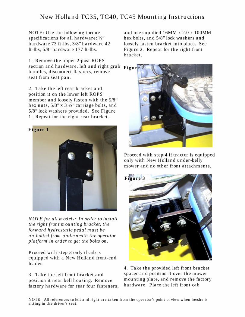
2. Take the left rear bracket andposition it on the lower left ROPSmember and loosely fasten with the 5/8”hex nuts, 5/8” x 3 ½” carriage bolts, and5/8” lock washers provided. See Figure1. Repeat for the right rear bracket.
NOTE for all models: In order to installthe right front mounting bracket, theforward hydrostatic pedal must beun-bolted from underneath the operatorplatform in order to get the bolts on.
Proceed with step 3 only if cab isequipped with a New Holland front-endloader.
3. Take the left front bracket andposition it near bell housing. Removefactory hardware for rear four fasteners,
and use supplied 16MM x 2.0 x 100MMhex bolts, and 5/8” lock washers andloosely fasten bracket into place. SeeFigure 2. Repeat for the right frontbracket.
Proceed with step 4 if tractor is equipped only with New Holland under-bellymower and no other front attachments.
4. Take the provided left front bracketspacer and position it over the mowermounting plate, and remove the factoryhardware. Place the left front cab
NOTE: All references to left and right are taken from the operator’s point of view when he/she issitting in the driver’s seat.
New Holland TC35, TC40, TC45 Mounting Instructions
Figure 1
Figure 2
Figure 3
bracket over the spacer, and use supplied 16MM x 2.0 x 100MM hex bolts, and 5/8” lock washers and loosely fasten bracketinto place. See Figure 3. Repeat for theright front bracket.
Proceed with step 5 if tractor has noattachments on the bell housing.
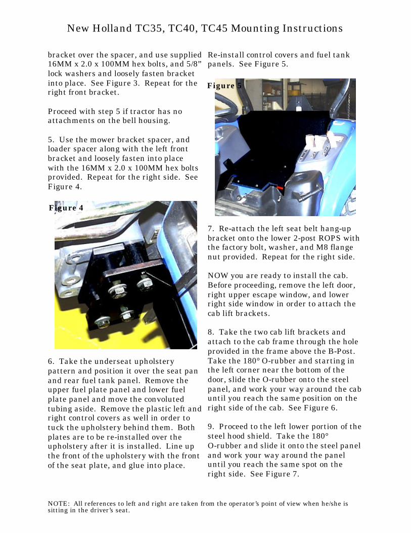
5. Use the mower bracket spacer, andloader spacer along with the left frontbracket and loosely fasten into placewith the 16MM x 2.0 x 100MM hex boltsprovided. Repeat for the right side. SeeFigure 4.
6. Take the underseat upholsterypattern and position it over the seat panand rear fuel tank panel. Remove theupper fuel plate panel and lower fuelplate panel and move the convolutedtubing aside. Remove the plastic left and right control covers as well in order totuck the upholstery behind them. Bothplates are to be re-installed over theupholstery after it is installed. Line upthe front of the upholstery with the frontof the seat plate, and glue into place.
Re-install control covers and fuel tankpanels. See Figure 5.
7. Re-attach the left seat belt hang-upbracket onto the lower 2-post ROPS with the factory bolt, washer, and M8 flangenut provided. Repeat for the right side.
NOW you are ready to install the cab. Before proceeding, remove the left door,right upper escape window, and lowerright side window in order to attach thecab lift brackets.
8. Take the two cab lift brackets andattach to the cab frame through the holeprovided in the frame above the B-Post. Take the 180° O-rubber and starting inthe left corner near the bottom of thedoor, slide the O-rubber onto the steelpanel, and work your way around the cab until you reach the same position on theright side of the cab. See Figure 6.
9. Proceed to the left lower portion of the steel hood shield. Take the 180° O-rubber and slide it onto the steel panel and work your way around the paneluntil you reach the same spot on theright side. See Figure 7.
NOTE: All references to left and right are taken from the operator’s point of view when he/she issitting in the driver’s seat.
New Holland TC35, TC40, TC45 Mounting Instructions
Figure 4
Figure 5
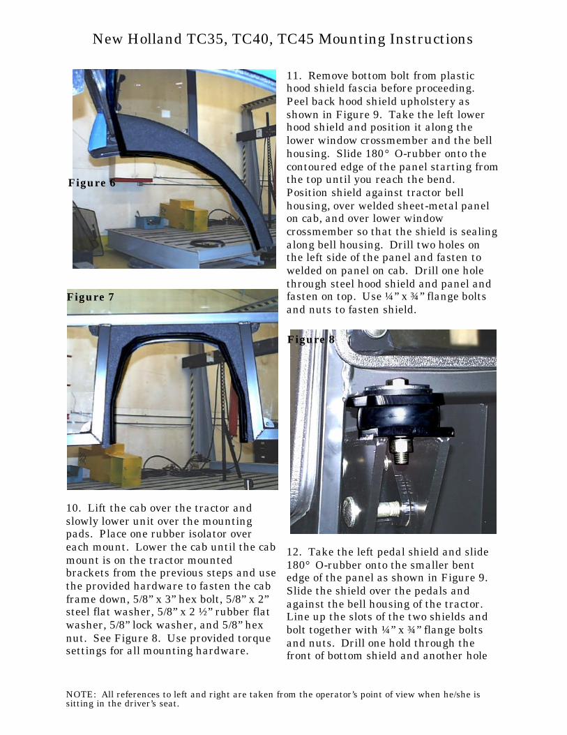
10. Lift the cab over the tractor andslowly lower unit over the mountingpads. Place one rubber isolator overeach mount. Lower the cab until the cabmount is on the tractor mountedbrackets from the previous steps and use the provided hardware to fasten the cabframe down, 5/8” x 3” hex bolt, 5/8” x 2”steel flat washer, 5/8” x 2 ½” rubber flatwasher, 5/8” lock washer, and 5/8” hexnut. See Figure 8. Use provided torquesettings for all mounting hardware.
11. Remove bottom bolt from plastichood shield fascia before proceeding. Peel back hood shield upholstery asshown in Figure 9. Take the left lowerhood shield and position it along thelower window crossmember and the bellhousing. Slide 180° O-rubber onto thecontoured edge of the panel starting from the top until you reach the bend. Position shield against tractor bellhousing, over welded sheet-metal panelon cab, and over lower windowcrossmember so that the shield is sealing along bell housing. Drill two holes onthe left side of the panel and fasten towelded on panel on cab. Drill one holethrough steel hood shield and panel andfasten on top. Use ¼” x ¾” flange boltsand nuts to fasten shield.
12. Take the left pedal shield and slide180° O-rubber onto the smaller bentedge of the panel as shown in Figure 9. Slide the shield over the pedals andagainst the bell housing of the tractor. Line up the slots of the two shields andbolt together with ¼” x ¾” flange boltsand nuts. Drill one hold through thefront of bottom shield and another hole
NOTE: All references to left and right are taken from the operator’s point of view when he/she issitting in the driver’s seat.
New Holland TC35, TC40, TC45 Mounting Instructions
Figure 6
Figure 7
Figure 8
through the platform extension behindthe mounting bracket plate. Useprovided hardware to fasten.
13. Repeat steps 11 and 12 for the rightside, and use Figure 10.
14. Take the left pedal floormat andpostion over the shield installed in step12. Glue floormat into place. See Figure 11. Repeat for the right pedal floormat.
If cab is equipped with the heater optionproceed with the following steps.
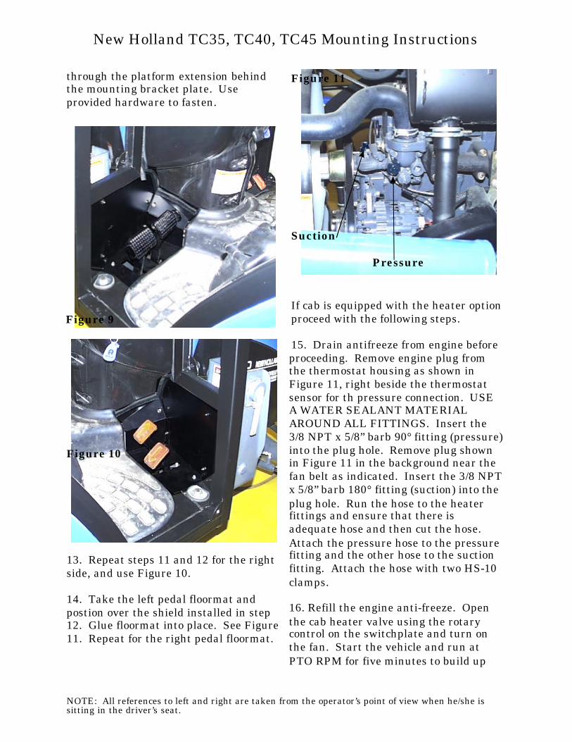
15. Drain antifreeze from engine beforeproceeding. Remove engine plug from the thermostat housing as shown inFigure 11, right beside the thermostatsensor for th pressure connection. USEA WATER SEALANT MATERIALAROUND ALL FITTINGS. Insert the3/8 NPT x 5/8” barb 90° fitting (pressure) into the plug hole. Remove plug shownin Figure 11 in the background near thefan belt as indicated. Insert the 3/8 NPT x 5/8” barb 180° fitting (suction) into theplug hole. Run the hose to the heaterfittings and ensure that there isadequate hose and then cut the hose. Attach the pressure hose to the pressurefitting and the other hose to the suctionfitting. Attach the hose with two HS-10clamps.
16. Refill the engine anti-freeze. Openthe cab heater valve using the rotarycontrol on the switchplate and turn onthe fan. Start the vehicle and run atPTO RPM for five minutes to build up
NOTE: All references to left and right are taken from the operator’s point of view when he/she issitting in the driver’s seat.
New Holland TC35, TC40, TC45 Mounting Instructions
Figure 9
Figure 10
Figure 11
Suction
Pressure
engine heat. Check for leaks and addanti-freeze if required. For maximumheater efficiency, all air trapped in theheater system must be evacuated. Continue running the engine and addingantifreeze as required until cab heaterproduces hot air. TIP: when purgingsystem of air, open radiator cap whenrunning the engine.
17. Once installation is complete, take ablack silicone sealant and seal allshields, floormat, and upholstery.
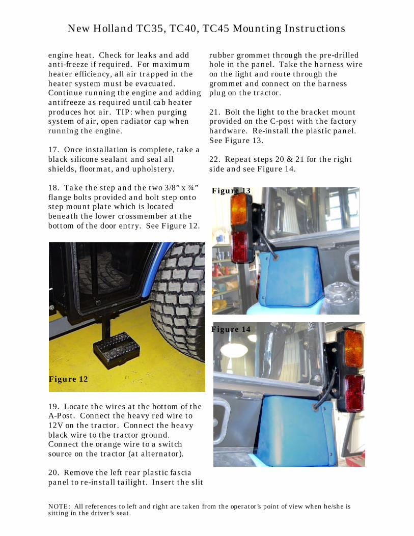
18. Take the step and the two 3/8” x ¾”flange bolts provided and bolt step ontostep mount plate which is locatedbeneath the lower crossmember at thebottom of the door entry. See Figure 12.
19. Locate the wires at the bottom of the A-Post. Connect the heavy red wire to12V on the tractor. Connect the heavyblack wire to the tractor ground. Connect the orange wire to a switchsource on the tractor (at alternator).
20. Remove the left rear plastic fasciapanel to re-install tailight. Insert the slit
rubber grommet through the pre-drilledhole in the panel. Take the harness wire on the light and route through thegrommet and connect on the harnessplug on the tractor.
21. Bolt the light to the bracket mountprovided on the C-post with the factoryhardware. Re-install the plastic panel. See Figure 13.
22. Repeat steps 20 & 21 for the rightside and see Figure 14.
NOTE: All references to left and right are taken from the operator’s point of view when he/she issitting in the driver’s seat.
New Holland TC35, TC40, TC45 Mounting Instructions
Figure 12
Figure 13
Figure 14