Embed Size (px)
Citation preview
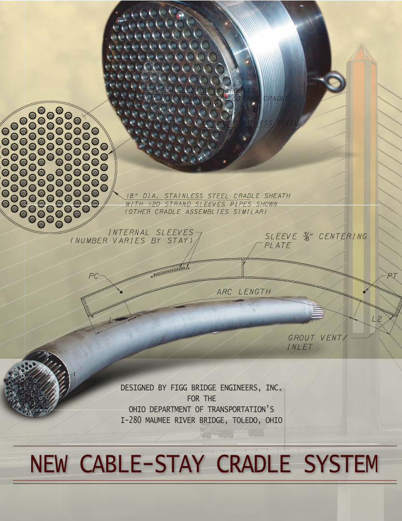
DESIGNED BY FIGG BRIDGE ENGINEERS, INC.
FOR THE
OHIO DEPARTMENT OF TRANSPORTATION’S
I-280 MAUMEE RIVER BRIDGE, TOLEDO, OHIO
NEW CABLE-STAY CRADLE SYSTEM
INTRODUCTION
December 2001 brought thesuccessful completion of all testingassociated with the innovative newcradle stay system designed byFigg Engineering Group (FIGG) forinitial use on the Maumee RiverCrossing Bridge (1.2 million squarefoot bridge deck) in Toledo, Ohiofor the Ohio Department ofTransportation (ODOT).
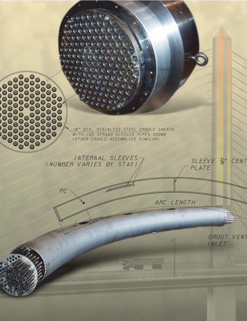
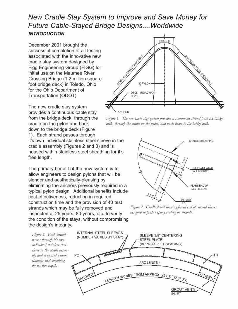
The new cradle stay systemprovides a continuous cable stayfrom the bridge deck, through thecradle on the pylon and backdown to the bridge deck (Figure1). Each strand passes throughit’s own individual stainless steel sleeve in thecradle assembly (Figures 2 and 3) and ishoused within stainless steel sheathing for it’sfree length.
The primary benefit of the new system is toallow engineers to design pylons that will beslender and aesthetically-pleasing byeliminating the anchors previously required in atypical pylon design. Additional benefits includecost-effectiveness, reduction in requiredconstruction time and the provision of 40 teststrands which may be fully removed andinspected at 25 years, 80 years, etc. to verifythe condition of the stays, without compromisingthe design’s integrity.
New Cradle Stay System to Improve and Save Money forFuture Cable-Stayed Bridge Designs....Worldwide
CRADLE
C PYLONLSTAINLE
SS STEEL S
HEATHING
ANCHOR
DECK (ROADWAY)LEVEL
STAINLESS STEEL SHEATHING
Figure 1. The new cable stay system provides a continuous strand from the bridgedeck, through the cradle on the pylon, and back down to the bridge deck.
INTERNAL STEEL SLEEVES(NUMBER VARIES BY STAY) SLEEVE 3/8" CENTERING
STEEL PLATE(APPROX. 5 FT SPACING)
TANGENTTANGENT
GROUT VENT/INLET
PC PT
LENGTH VARIES FROM APPROX. 29 FT. TO 37 FT.
ARC LENGTH
Figure 3. Each strandpasses through it’s ownindividual stainless steelsleeve in the cradle assem-bly and is housed withinstainless steel sheathingfor it’s free length.
CRADLE SHEATHING
1/8" FILLET WELD(ALL AROUND)
FLARE END OFEACH SLEEVE
3/8" END PLATE
2 1/4"
1 1/
4"
Figure 2. Cradle detail showing flared end of strand sleevesdesigned to protect epoxy coating on strands.
Testing of the new system included material/production/acceptance testing for the components of the stay cables, alongwith fatigue and strength testing of full-scale cable assembliesand was conducted by CTL (Construction Testing Laboratories,Inc.) under contract to ODOT. All tests were conducted inaccordance with the PTI requirements and reviewed in advanceby the FHWA.
MAUMEE RIVER CROSSING - an initial application
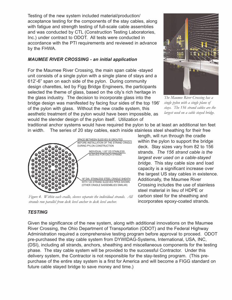
For the Maumee River Crossing, the main span cable -stayedunit consists of a single pylon with a single plane of stays and a612’-6” span on each side of the pylon. During communitydesign charettes, led by Figg Bridge Engineers, the participantsselected the theme of glass, based on the city’s rich heritage inthe glass industry. The decision to incorporate glass into thebridge design was manifested by facing four sides of the top 196’of the pylon with glass. Without the new cradle system, thisaesthetic treatment of the pylon would have been impossible, aswould the slender design of the pylon itself. Utilization oftraditional anchor systems would have required the pylon to be at least an additional ten feetin width. The series of 20 stay cables, each inside stainless steel sheathing for their free
length, will run through the cradlewithin the pylon to support the bridgedeck. Stay sizes vary from 82 to 156strands. The 156 strand cable is thelargest ever used on a cable-stayedbridge. This stay cable size and loadcapacity is a significant increase overthe largest US stay cables in existence.Additionally, the Maumee RiverCrossing includes the use of stainlesssteel material in lieu of HDPE orcarbon steel for the sheathing andincorporates epoxy-coated strands.
TESTING
Given the significance of the new system, along with additional innovations on the MaumeeRiver Crossing, the Ohio Department of Transportation (ODOT) and the Federal HighwayAdministration required a comprehensive testing program before approval to proceed. ODOTpre-purchased the stay cable system from DYWIDAG-Systems, International, USA, INC,(DSI), including all strands, anchors, sheathing and miscellaneous components for the testingphase. The stay cable system will be provided to the successful Contractor. Under thisdelivery system, the Contractor is not responsible for the stay-testing program. (This pre-purchase of the entire stay system is a first for America and will become a FIGG standard onfuture cable stayed bridge to save money and time.)
The Maumee River Crossing has asingle pylon with a single plane ofstays. The 156 strand cables are thelargest used on a cable stayed bridge.
SPACE BETWEEN SLEEVES IS GROUTEDBEFORE INSTALLATION OF THE STRAND CRADLEDURING PYLON CONSTRUCTION
INDIVIDUAL 1.00" OD STAINLESSSLEEVES FOR EACH STRAND
18" DIA. STAINLESS STEEL CRADLE SHEATHWITH 120 STRAND SLEEVES PIPES SHOWN(OTHER CRADLE SASSEMBLIES SIMILAR)
Figure 4. Within each cradle, sleeves separate the individual strands. Allstrands run parallel from deck level anchor to deck level anchor.
The acceptance testing program consisted of the following tests:
Axial fatigue and ultimate static test of an 82-strand specimen that is fullyrepresentative of all materials, details, fabrication and assembly procedures proposed forproduction anchorages. Each specimen consisted of two anchorages with a clear spaceof approximately 180 inches between anchor faces.
Axial fatigue and leak test of a 119-strand specimen. In addition the the fatiguetesting of the specimen and, as part of the corrosion protection qualification of theanchorage assembly, the stay cable anchorage specimen, complete with transition zone,a minimum of one meter of free length, and all seals,coatings and coverings that will be installed in theactual application were subjected to a leak test.
Axial fatigue and ultimate static test of a 156-strand specimen (a world record for stay size) that isfully representative of all materials, details, fabricationand assembly procedures proposed for productionanchorages. Each specimen consisted of twoanchorages with a clear space of approximately 180inches between anchor faces.
Single strand cradle testing. Prior to conductinga test of the full size cradle specimen for the combinedaxial/flexural fatigue test, three similar tests (each witha different radius) were conducted one one-strandspecimens. The purpose of these single strand testswas twofold. First, it provided a value for the frictioncoefficient between the epoxy-coated stay cable strandand the stainless steel sleeve inside the cradle.Second, it provided an initial indication of the fatiguebehavior of the epoxy-coated stay cable strandinteraction with the stainless steel sleeve.
Axial/flexural (Cradle Test) test of a 119-strandspecimen. The specimen for the test was fullyrepresentative of all materials, details, fabrication andassembly procedures proposed for the production anchorages and stay cable cradles.The specimen consisted of two anchorages and one complete stay cable cradleassembly.
Acceptance testing was done in accordance with the 1993 PTI Recommendations for StayCable Design, Testing and Installation (and included the leak test which was adopted fromthe 2000 edition). All testing was completed successfully in early December, 2001.
OUTCOMEThe successful completion of the testing phase validated the FIGG-designed cradlesystem and allowed the Maumee River Crossing to move forward to bid on January 17,2002. It also offers ODOT many benefits:
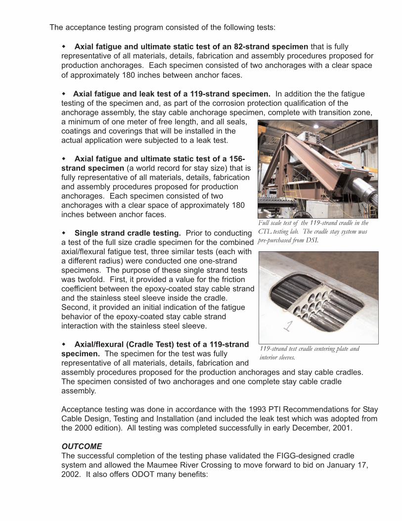
Full scale test of the 119-strand cradle in theCTL testing lab. The cradle stay system waspre-purchased from DSI.
119-strand test cradle centering plate and interior sleeves.
Cost-effectiveness with savings of over $3 million on the Maumee River CrossingBridge. When cable stay anchors are used in pylons, the pylons need to be large enoughto permit internal access during construction for stressing operations of the stays and forinspection of the anchors after construction. Also, significant additional reinforcing isneeded to overcome the large splitting stresses in the concrete pylon. By using our cradleinternal to the pylon, access requirements are eliminated allowing the use of a smallerpylon cross section, saving not only concrete and steel, but also construction time.Additionally, the unit cost of a cradle is lower than that of the two anchors it replaces.
Perceived concerns about strand-to-strand interaction in the curved portion of the cableare eliminated by the use of individual sleeves inside the cradle for each strand. Allstrands run parallel from anchor at deck level to cradle to anchor at deck level.
Allows use of a continuous primary tensile element from deck level anchor to deck level anchor.
The load transfer to the concrete pylon occurs in a natural compressive contact stress applied vertically to the pylon. Not only is this a more desirable structural condition, but italso saves time and money since no additional reinforcing is required in the pylon tocontrol the high splitting forces introduced into a pylon by the use of anchors in the pylon.
Provides the flexibility of 40 "reference" strands that can be removed in entirety atdesired time intervals for inspection...15 years, 50 years, etc. so that ODOT will alwaysknow the condition of the stays. This is the only cable stay system with this “fool proof”stay inspection system.
CONCLUSION
“The new system that we have designed will revolutionize the design of cable-stayed bridges.This system provides a solution that eliminates stay anchors in the pylon and allowsdesigners to create slender pylons with unique shapes, saves money and provides pleasingaesthetics. It also allows for easy inspection of the stays at 20 years, 75 years, etc. in thefuture.”, W. Denney Pate, P.E., senior vice president and principal bridge engineer at FiggBridge Engineers.
The innovative cable stay cradle system designed by Figg Engineering Group, initially for theMaumee River Crossing, and for use on future cable stay bridges, will revolutionize cable staybridge design. It will allow this type of bridge to be even more economical, thus attractive formany major spans around the world. The elimination of pylon anchors allows the designingengineer to utilize a wide variety of shapes and aesthetics in designing the pylons of cable-stayed bridges. This greater freedom will encourage engineers to design bridges as art.