Embed Size (px)
Citation preview

NEUTRON IRRADIATION EFFECTS ONMICROWAVE TRANSISTOR AMPLIFIERS*
J. G. Webb and R. J. ChaffinSandia Laboratories
Albuquerque, New Mexico
Abstract
Studies are presented of neutron irradi-ation effects on microwave bipolar transistorsin two applications--small signal, low noiseamplifiers and large signal, power amplifiers.In both applications microwave transistors arefound to be neutron tolerant. In the lownoise case, the amplifier noise figure in-creases by less thgn 1 d! after a neutronfluence of 2 x 101 n/cm (E > 10 keV). Theobserved degradation in noise figure isrelated both theoretically and experimentallyto neutron-induced decreases in DC and lowfrequency current gain, and good agreement isfound. In the power amplifier case, saturatedoutput power and power gain decrease by 1.8and 3 dB, respectively, after 2 x 10¹⁵ n/cm2.The change in saturated output power is re-lated to increased high frequency Ve(sat),while the decreased gain is due to ecreasedhigh frequency current gain. Neutron effectson these transistor parameters are calculatedfrom the power output and gain data, and com-pared with radiation effects on these param-eters at low frequencies.
Introduction
Recent technological advances have ex-tended the frequency range of the bipolartransistor into the low microwave range. Twoimportant applications of these devices arefound in low noise, small signal amplifiersand in high efficiency, high power amplifiers.This paper investigates the effect of neutronfluence on the noise performance, power gain,and power output of microwave bipolar tran-sistor amplifiers.
Low Noise Amplifiers
Previous authorsl'2 have studied theeffects of gamma and neutron radiation on thelow frequency noise behavior of bipolar andfield effect transistors. They have foundlarge increases in the output noise of thesedevices at fairly low radiation fluences.This has been attributed to surface effectsand increased generation-recombination noise.Flicker noise (1/f), surface noise, andgeneration-recombination noise are low-fre-quency effects and should not be important atmicrowave frequencies. Therefore, the radia-tion damage produced generation-recombinationcenters should not be of direct important tothe microwave transistor noise figure. Hence,the only degradation in microwave transistornoise performance due to irradiation shouldcome about indirectly because of changes intransistor parameters (a, 3, etc.) with radi-ation. The noise figure of high-frequencytransistors has been studied by many
*This work was supported by the United
States Atomic Energy Commission.
authors.3'4 The principal sources of noisewithin a microwave transistor are shot noisedue to the emitter and collector currents andthermal noise in the base resistance. Fukui4has shown that the noise figure of a micro-wave bipolar transistor can be expressed(ignoring header parasitic effects) as:
F = (1 + )( +Rg kT2eI R
c g
eI 2[l+ c (r + R )L
2kTR9 b g/nd
+L12so
+ f 2
(1)where SO = low frequency current gain,5dc = Ic/IB, e = electronic charge, R = inputsource impedance, fT = unity gain fre&uency,and f = operating frequency.
If no new high-frequency noise sourcesare introduced into the transistor by radi-ation, then the noise figure of a microwavetransistor amplifier should still be pre-dicted by Eq. 1 in the post-irradiated case.To test this theory, a 1.2 GHz amplifier wasconstructed using a Hewlett-Packard hp-35821Emicrowave bipolar transistor. This tran-sistor has an fT of approximately 4 GHz. Theamplifier had a pre-rad gain of 10 dB and apre-rad noise figure of 3.9 dB. Ten tran-sistors were used in the test with two beingheld as controls. The transistors wereneutron irradiated at the Sandia ACPR andthen replaced in the amplifier and its gainand noise figure were remeasured. The col-lector current was held constant at 10 mA forall measurements. The experimental dataobtained are shown in Figures 1 and 2. (Theseare 8 sample averages, although the variancewas less than 0.5 dB from sample to sample.)Figure 2 shows the measured noise figure aswell as the theoretical values of noisefigure predicted by Eq. 1. The effect ofneutron irradiation was brought into Eq. 1through variation of SO (Fig. 1) and 5dc withneutron fluence. Figure 2 shows that theexperimental data agree very well with thetheoretical prediction of Eq. 1. The valuesused in Eq. 1 are rb = 40, fT = 4.1 GHz(typical for the 35821E transistor), Rg = 50Q,IC = 0.01A, and T = 2900K. The effects ofneutron fluence on r] and fT were ignored.However, a decrease in fT at high fluencelevels has been observed.5 This would tend toimprove the agreement between experiment andtheory at high fluences. The agreementbetween experiment and theory implies that theoriginal hypothesis, that no new high-frequen-cy noise sources are introduced by neutronirradiation of microwave bipolar transistors,is correct.
340
Power Amplifiers
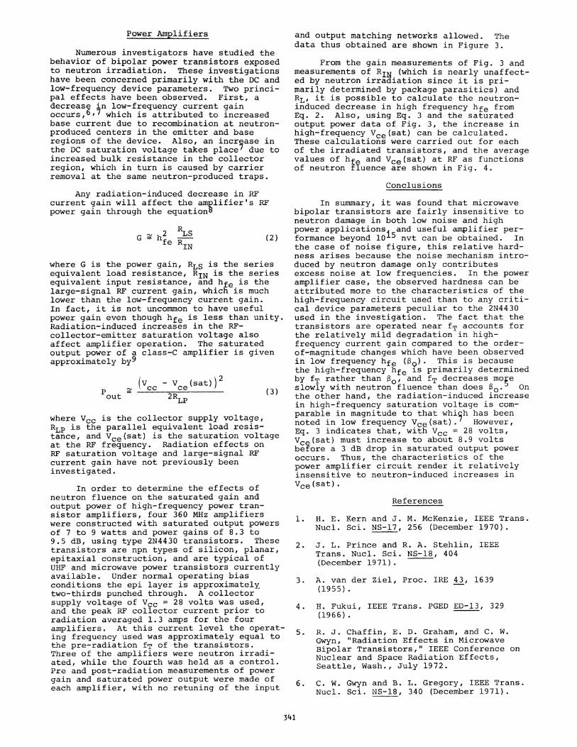
Numerous investigators have studied thebehavior of bipolar power transistors exposedto neutron irradiation. These investigationshave been concerned primarily with the DC andlow-frequency device parameters. Two princi-pal effects have been observed. First, adecrease in low-frequency current gainoccurs,6,7 which is attributed to increasedbase current due to recombination at neutron-produced centers in the emitter and baseregions of the device. Also, an increase inthe DC saturation voltage takes place7 due toincreased bulk resistance in the collectorregion, which in turn is caused by carrierremoval at the same neutron-produced traps.
Any radiation-induced decrease in RFcurrent gain will affect the amplifier's RFpower gain through the equation8
2RLhfe RIN(2)
where G is the power gain, RLS is the seriesequivalent load resistance, RIN is the seriesequivalent input resistance, and hfe is thelarge-signal RF current gain, which is muchlower than the low-frequency current gain.In fact, it is not uncommon to have usefulpower gain even though hfe is less than unity.Radiation-induced increases in the RF-collector-emitter saturation voltage alsoaffect amplifier operation. The saturatedoutput power of a class-C amplifier is givenapproximately by9
(Vcc - Vce(sat))2out 2RLP(3
where Vcc is the collector supply voltage,RLP is the parallel equivalent load resis-tance, and Vce(sat) is the saturation voltageat the RF frequency. Radiation effects onRF saturation voltage and large-signal RFcurrent gain have not previously beeninvestigated.
In order to determine the effects ofneutron fluence on the saturated gain andoutput power of high-frequency power tran-sistor amplifiers, four 360 MHz amplifierswere constructed with saturated output powersof 7 to 9 watts and power gains of 8.3 to9.5 dB, using type 2N4430 transistors. Thesetransistors are npn types of silicon, planar,epitaxial construction, and are typical ofUHF and microwave power transistors currentlyavailable. Under normal operating biasconditions the epi layer is approximatelytwo-thirds punched through. A collectorsupply voltage of Vcc = 28 volts was used,and the peak RF collector current prior toradiation averaged 1.3 amps for the fouramplifiers. At this current level the operat-ing frequency used was approximately equal tothe pre-radiation fT of the transistors.Three of the amplifiers were neutron irradi-ated, while the fourth was held as a control.Pre and post-radiation measurements of powergain and saturated power output were made ofeach amplifier, with no retuning of the input
and output matching networks allowed. Thedata thus obtained are shown in Figure 3.
From the gain measurements of Fig. 3 andmeasurements of RIg (which is nearly unaffect-ed by neutron irradiation since it is pri-marily determined by package parasitics) andRL, it is possible to calculate the neutron-induced decrease in high frequency hfe fromEq. 2. Also, using Eq. 3 and the saturatedoutput power data of Fig. 3, the increase inhigh-frequency Vce(sat) can be calculated.These calculations were carried out for eachof the irradiated transistors, and the averagevalues of hfe and Vce(sat) at RF as functionsof neutron fluence are shown in Fig. 4.
Conclusions
In summary, it was found that microwavebipolar transistors are fairly insensitive toneutron damage in both low noise and highpower applications and useful amplifier per-formance beyond 10'5 nvt can be obtained. Inthe case of noise figure, this relative hard-ness arises because the noise mechanism intro-duced by neutron damage only contributesexcess noise at low frequencies. In the poweramplifier case, the observed hardness can beattributed more to the characteristics of thehigh-frequency circuit used than to any criti-cal device parameters peculiar to the 2N4430used in the investigation. The fact that thetransistors are operated near fT accounts forthe relatively mild degradation in high-frequency current gain compared to the order-of-magnitude changes which have been observedin low frequency hfe (39). This is becausethe high-frequency hfe is primarily determinedby fT rather than 13, and fT decreases moreslowly with neutron fluence than does SO. Onthe other hand, the radiation-induced increasein high-frequency saturation voltage is com-parable in magnitude to that whi5h has beennoted in low frequency Vce(sat). However,Eq. 3 indicates that, with Vcc = 28 volts,Vce(sat) must increase to about 8.9 voltsbefore a 3 dB drop in saturated output poweroccurs. Thus, the characteristics of thepower amplifier circuit render it relativelyinsensitive to neutron-induced increases invce(sat).
References
1. H. E. Kern and J. M. McKenzie, IEEE Trans.Nucl. Sci. NS-17, 256 (December 1970).
2. J. L. Prince and R. A. Stehlin, IEEETrans. Nucl. Sci. NS-18, 404(December 1971).
3. A. van der Ziel, Proc. IRE 43, 1639(1955).
4. H. Fukui, IEEE Trans. PGED ED-13, 329(1966).
5. R. J. Chaffin, E. D. Graham, and C. W.Gwyn, "Radiation Effects in MicrowaveBipolar Transistors," IEEE Conference onNuclear and Space Radiation Effects,Seattle, Wash., July 1972.
6. C. W. Gwyn and B. L. Gregory, IEEE Trans.Nucl. Sci. NS-18, 340 (December 1971).
341

7. J. A. Hood, Sandia Corporation ReportSC-TM-64-69, March 1964.
8. R. A. Battisti and K. 0. Morey, TRWSemiconductors Applications Note,"Amplifier and Oscillator Applications
35 - -
30 -
2525
_z0
15 hp - 35821E
1c 10-
10
of the Gigahertz Family of UHFTransistors."
9. P. M. Chirlian, Analysis and Design ofElectronic Circuits, McGraw-Hill, 1965,ch. 8.
NEUTRON FLUENCE - nkum2, (E >10 keY)
Figure 1. Low frequency current gainversus neutron fluence (hp 35821E).
00
z
-j
NEUTRON FLUENCE - nkm2 (E > 10 kW)
Figure 2. Theoretical and experimentalnoise figure versus neutron fluence(hp 35821E).
342

1016NEUTRON FLUENCE -nlcm2 (E>lOKeV)
Figure 3. Power amplifier gain andsaturated output power versus neutronfluence (2N4430).
4,
zI
cI(9I
NEUTRON FLUENCE-nicm2(E>10KeV)
Figure 4. High frequency large signalcurrent gain and saturation voltageversus neutron fluence (2N4430).
343
cIo z
o0<
a)
14
4(
zWD0W
LL
I
I