Embed Size (px)
Citation preview

NEURON DESIGN IN NEUROMORPHIC COMPUTING SYSTEMS AND ITS APPLICATION IN WIRELESS COMMUNICATIONS
THE UNIVERSITY OF KANSAS CENTER FOR RESEARCH, INC. MARCH 2017 FINAL TECHNICAL REPORT
APPROVED FOR PUBLIC RELEASE; DISTRIBUTION UNLIMITED
STINFO COPY
AIR FORCE RESEARCH LABORATORY INFORMATION DIRECTORATE
AFRL-RI-RS-TR-2017-057
UNITED STATES AIR FORCE ROME, NY 13441 AIR FORCE MATERIEL COMMAND

NOTICE AND SIGNATURE PAGE
Using Government drawings, specifications, or other data included in this document for any purpose other than Government procurement does not in any way obligate the U.S. Government. The fact that the Government formulated or supplied the drawings, specifications, or other data does not license the holder or any other person or corporation; or convey any rights or permission to manufacture, use, or sell any patented invention that may relate to them.
This report is the result of contracted fundamental research deemed exempt from public affairs security and policy review in accordance with SAF/AQR memorandum dated 10 Dec 08 and AFRL/CA policy clarification memorandum dated 16 Jan 09. This report is available to the general public, including foreign nationals. Copies may be obtained from the Defense Technical Information Center (DTIC) (http://www.dtic.mil).
AFRL-RI-RS-TR-2017-057 HAS BEEN REVIEWED AND IS APPROVED FOR PUBLICATION IN ACCORDANCE WITH ASSIGNED DISTRIBUTION STATEMENT.
FOR THE CHIEF ENGINEER:
/ S / MICHAEL J. MEDLEY Work Unit Manager
/ S / JOHN D. MATYJAS Technical Advisor, Computing & Communications Division Information Directorate
This report is published in the interest of scientific and technical information exchange, and its publication does not constitute the Government’s approval or disapproval of its ideas or findings.

REPORT DOCUMENTATION PAGE Form Approved OMB No. 0704-0188
The public reporting burden for this collection of information is estimated to average 1 hour per response, including the time for reviewing instructions, searching existing data sources, gathering and maintaining the data needed, and completing and reviewing the collection of information. Send comments regarding this burden estimate or any other aspect of this collection of information, including suggestions for reducing this burden, to Department of Defense, Washington Headquarters Services, Directorate for Information Operations and Reports (0704-0188), 1215 Jefferson Davis Highway, Suite 1204, Arlington, VA 22202-4302. Respondents should be aware that notwithstanding any other provision of law, no person shall be subject to any penalty for failing to comply with a collection of information if it does not display a currently valid OMB control number. PLEASE DO NOT RETURN YOUR FORM TO THE ABOVE ADDRESS. 1. REPORT DATE (DD-MM-YYYY)
MARCH 2017 2. REPORT TYPE
FINAL TECHNICAL REPORT 3. DATES COVERED (From - To)
FEB 2015 – SEP 2016 4. TITLE AND SUBTITLE
NEURON DESIGN IN NEUROMORPHIC COMPUTING SYSTEMS AND ITS APPLICATION IN WIRELESS COMMUNICATIONS
5a. CONTRACT NUMBER
5b. GRANT NUMBER FA8750-15-1-0052
5c. PROGRAM ELEMENT NUMBER 62702F
6. AUTHOR(S)
Yang Yi
5d. PROJECT NUMBER T2RB
5e. TASK NUMBER KU
5f. WORK UNIT NUMBER YY
7. PERFORMING ORGANIZATION NAME(S) AND ADDRESS(ES)The University of Kansas Center for Research, Inc. 2385 Irving Hill Road Lawrence, KS 66045-7568
8. PERFORMING ORGANIZATIONREPORT NUMBER
9. SPONSORING/MONITORING AGENCY NAME(S) AND ADDRESS(ES)
Air Force Research Laboratory/RITF 525 Brooks Road Rome NY 13441-4505
10. SPONSOR/MONITOR'S ACRONYM(S)
AFRL/RI 11. SPONSOR/MONITOR’S REPORT NUMBER
AFRL-RI-RS-TR-2017-057 12. DISTRIBUTION AVAILABILITY STATEMENTApproved for Public Release; Distribution Unlimited. This report is the result of contracted fundamental research deemed exempt from public affairs security and policy review in accordance with SAF/AQR memorandum dated 10 Dec 08 and AFRL/CA policy clarification memorandum dated 16 Jan 09. 13. SUPPLEMENTARY NOTES
14. ABSTRACTThe objective of this effort is to: (a) develop novel and fundamental methodologies for data representation using hardware spike timing dependent encoding for neuromorphic processors; (b) explore the applications of neuromorphic computing in channel estimation for the Multiple-Input and Multiple-Output (MIMO) communications. This project will introduce an interdisciplinary approach for exploring the application of neuromorphic computing in wireless communications. This will bridge high-performance computing, nanotechnology, and telecommunications, as well as improve the computational efficiency and accuracy of channel estimation in MIMO communications. The project’s envisioned architecture will serve as the foundation for unprecedented capabilities in real-time applications such as the MIMO channel estimation that fall within Air Force Research Lab (AFRL) communication and computing consolidated programs.
15. SUBJECT TERMSSpike timing, neuromorphic computing, reservoir computing, channel estimation in MIMO communications
16. SECURITY CLASSIFICATION OF: 17. LIMITATION OF ABSTRACT
UU
18. NUMBEROF PAGES
19a. NAME OF RESPONSIBLE PERSON MICHAEL J. MEDLEY
a. REPORT U
b. ABSTRACT U
c. THIS PAGEU
19b. TELEPHONE NUMBER (Include area code) N/A
Standard Form 298 (Rev. 8-98) Prescribed by ANSI Std. Z39.18
47
i
TABLE OF CONTENTS
Section Page
List of Figures . . . . . . . . . . . . . . . . . . . . . . . . . . . . . . . . . . . . . . . . . . . . . . . . . . . . . . . . . . . . . . . . ii
List of Tables . . . . . . . . . . . . . . . . . . . . . . . . . . . . . . . . . . . . . . . . . . . . . . . . . . . . . . . . . . . . . . . iii 1.0 SUMMARY . . . . . . . . . . . . . . . . . . . . . . . . . . . . . . . . . . . . . . . . . . . . . . . . . . . . . . . . . . . . . . 1
2.0 INTRODUCTION . . . . . . . . . . . . . . . . . . . . . . . . . . . . . . . . . . . . . . . . . . . . . . . . . . . . . . . . . 2
3.0 METHODS, ASSUMPTIONS, AND PROCEDURES. . . . . . . . . . . . . . . . . . . . . . . . . . . . . . 5
3.1 ANALOG NEURON DESIGN IN NEUROMORPHIC COMPUTING. . . . . . . . . . . . . . . . 7
3.2 APPLICATION OF NEUROMORPHIC COMPUTING IN WIRELESS
COMMUNICATIONS. . . . . . . . . . . . . . . . . . . . . . . . . . ………... . . . . . . . . . . . . . . . . . . . . . . . 19
4.0 RESULTS AND DISCUSSION. . . . . . . . . . . . . . . . . . . . . . . . . . . . . . . . . . . . . . . . . . . . . . . . . . . . .24
4.1 PERFORMANCE ANAYSIS OF ANALOG NEURONS…………………………………..24
4.2 PERFORMANCE EVALUATION AND DISCUSSION OF RC-BASED CHANNEL
ESTIMATION………………………………………………………………………………….. 28
5.0 CONCLUSIONS . . . . . . . . . . . . . . . . . . . . . . . . . . . . . . . . . . . . . . . . . . . . . . . . . . . . . . . . . . .30
6.0 REFERENCES. . . . . . . . . . . . . . . . . . . . . . . . . . . . . . . . . . . . . . . . . . . . . . . . . . . . . . . . . . . . . . .32
APPENDIX – PUBLICATIONS AND PRESENTATIONS ………………………………….33
LIST OF SYMBOLS, ABBREVIATIONS, AND ACRONYMS………………………………40

ii
Figure Page 1 Action Potential of Biological Neuron. . . . …… . . . . . . . .. . . . . . . . . .. . . . . . . . . ……. . . . . . 8
2 Simplified Circuits for (a) Integrate-and-fire model; (b) Hodgkin-Huxley Model; (c) Fitzhugh
Nagumo Model; (d) Leaky Integrate-and fire Model……………………..…….………………...9
3 Output Spike Train of LIF Neuron Model…………………………...…………………...……10
4 Examples of Rate Encode and Temporal Encode in Both Digital and Analog Form...…..11
5 System Structure of the Proposed Temporal Encoder……………………………………….14
6 Simplified Input Layer Circuit……………………………………………………………….14
7 Neuron Pool Signal Flow Diagram…………………………………………………………….15
8 Simplified Neuron Pool of the Proposed Temporal Encoder …………………………………16
9 Membrane Potential Variation Diagram and Relevant Active Elements……………………18
10 Output Layer Signal Flow Diagram…………………………………………………………18
11 Simplified Output Layer Circuit……………………………………………………………..19
12 Architecture of a delayed feedback reservoir with a nonlinear node and delay line………..20
13 Discrete-time equivalent baseband OFDM system…………………………………………22
14 General Model of Reservoir Computing System…………………………………………..23
15 Whole Layout View of the Encoder Chip……………………………………………………24
16 Single Neuron Layout View…………………………………………………………………25
17 Neuron Cluster Layout View………………………………………………………………..25
18 Post Simulation of the Proposed Temporal Encoder…………………………………………25
19 One Sample of the Post Simulation Results………………………………………………….26
20 Die Photo of the Proposed Temporal Encoder Chip…………………………………………26
21 Measurement Results of Two Samples……………………………………………………….26
22 Normalized Verification Value……………………………………………………………….27
23 Output Temporal Encode From the Chip……………………………………………………..27
24 Inspection Error…………………………………………………………………………… .27
25 BER for Different Number of Reservoir Neurons in MIMO OFDM System………………29
26 Bit Error Rate vs. Signal-to-noise Ratio for a nonlinear MIMO OFDM system……………..29
LIST OF FIGURES

iii
LIST OF TABLES
Table Page 1 Project Timeline Table . . . . . . . . . . . . . . . . . . . . . . . . . . . . . . . . . . . . . . . . . . . . . . . . . . . . . . . . . . . . .7
Approved for Public Release; Distribution Unlimited. 1
1.0 SUMMARY The objective of this effort is to: (a) develop novel and fundamental methodologies for data
representation using hardware spike timing dependent encoding for neuromorphic processors; (b) explore the applications of neuromorphic computing in channel estimation for the Multiple-Input and Multiple-Output (MIMO) communications. This project will introduce an interdisciplinary approach for exploring the application of neuromorphic computing in wireless communications. This will bridge high-performance computing, nanotechnology, and telecommunications, as well as improve the computational efficiency and accuracy of channel estimation in MIMO communications. The project’s envisioned architecture will serve as the foundation for unprecedented capabilities in real-time applications such as the MIMO channel estimation that fall within Air Force Research Lab (AFRL) communication and computing consolidated programs.
Approved for Public Release; Distribution Unlimited. 2
2.0 INTRODUCTION The Air Force is becoming a network-enabled paradigm, wherein many of its capabilities will
be generated through, and dependent on, the integrated efforts of multiple components. In general, robust dynamic tactical networks can support 10,000 to 500,000 communicating devices in theater. It goes beyond the traditional tactical network, which is oriented to the voice and human users, and beyond traditional ad hoc networks. Furthermore, the Air Force network must provide robust data and communication services to tens or hundreds of fixed and mobile users with different service levels. Some of the service challenges include guaranteed rates, communication over difficult channels, hard time-deadlines, security, and policy-driven resource allocation. These characteristics are primarily driven by defense needs.
As semiconductor technologies continue to scale further into the nanometer regime, it is
important to study how non-traditional computer architectures may be uniquely suited for many emerging technologies. Neuromorphic computing systems represent a type of non-traditional architecture. The emerging field of neuromorphic computing is close to achieving a critical mass that will enable significant improvement and novel applications to mission critical problems. Neuromorphic computers promise to solve a number of specific classes of stressing problems that clearly have not been solved by the leveraging of the current state-of-the-art in Complementary metal–oxide–semiconductor (CMOS) digital computing. Furthermore, there are growing expectations that functions difficult to perform efficiently even with large clusters of high-performance computers or supercomputers will one day be accomplished with neuromorphic processors that embody approaches to computing that are found in the natural world.
The scope of this proposed research is to develop a novel technology that builds integrated
computational environments for neuromorphic computing systems and distributes a set of advanced computational platforms based on this technology to achieve improved performance in channel estimation for MIMO communications. Comparing with current technologies, this project is to build a brain-like computing system with analog reservoir integrated circuits, which can offer potentially disruptive capabilities in the real time signature analysis, time series predictions, and the environmental perception for autonomous operations and dynamic control systems. The resulting dynamic time-series data will be processed using reservoir computing processors. Current predictive control strategies typically take the form of black-box systems. These systems are based on process models built from physical concepts and data-driven simulations that cannot cope with problems that have strong temporal aspects. By contrast, control systems built on the nonlinear dynamics of reservoir computing are capable of addressing these issues and have the potential to form the foundation for a new generation of deterministic adaptive processors.
The key technologies and components for successfully achieving the goals of this proposal are:
design and analysis of the spiking neuron with multiplexed temporal scales, development of a reservoir computing platform with time series spike encoding, application of reservoir computing to the multi-channel estimation in MIMO systems. The project can be summarized into two interconnected research thrusts:
1) Thrust 1: design and implement analog neuron for data representation using spike timing
dependent encoding in neuromorphic computing systems.

Approved for Public Release; Distribution Unlimited. 3
In the proposed research, we will compare the analog and digital implementations of neurons using Leaky Integrate-and-Fire (LIF) model, and design a robust and compact analog neuron using CMOS technology. We will show how signal-processing tasks can be modularly decomposed into elementary operators. Analog neurons were chosen rather than a digital implementation for power and area efficiency considerations. Design aspects such as integration time, threshold voltage, refractory period, and encoding resolution will be examined in an effort to optimize the adaptability and configurability of the neurons’ operational parameters. The designed neuron’s power consumption, area, robustness to process variability, and signal-to-noise ratio will also be reported.
2) Thrust 2: explore the application of reservoir computing in MIMO Communications. In this project, we will employ the reservoir computing to communication channel estimation in MIMO systems. Reservoir computing employs artificial recurrent neural networks in a way that has recently been proposed independently as a learning mechanism in biological brains. The learning method is computationally efficient and easy to use. We will apply reservoir computing to the channel estimation for MIMO systems (channel transfer matrix based estimation and parametric channel model based), and demonstrate its computational efficiency and accuracy improvement.
The proposed research will introduce an interdisciplinary approach for the spike timing
dependent encoding integrated circuit design, and explore the promising applications of neuromorphic computing in wireless communications. The implementation of real-time neuromorphic systems is ideal for the pattern and signature recognition in mobile platforms with severe size, weight, and power (SWAP) constraints. As a practical matter, such resource restrictions rule out traditional software approaches, which often require high-performance processing or run too slowly due to the inherent serial nature of von Neumann architectures.
We summarize the new technical ideas embodied by the research and list as follows:
• Robust and compact analog neuron design with CMOS technology, which exploits the physical characteristics of the hardware to more closely mimic biological neurons.
• Avoid using power-consuming analog-to-digital converters (ADCs) and operational amplifiers (Op-AMPs), leading to a substantial reduction in power consumption and die area in the design.
• Spike timing dependent encoder design with the inter-spike intervals (ISI) encoding, making use of the correlations between spike times that cannot be explained by rate modulations
• Application of reservoir computing to wireless communication and networks. Reservoir computing holds great promise for many important engineering and scientific applications. Such system exhibits rich dynamical behaviors within a simple architecture, and is capable of high-speed parallel signal processing. The expected impacts of the research are listed as follows:
• This work will result in an agile analog integrated-circuit implementation of a spike timing dependent encoding circuit as a signal conditioner for reservoir computing systems.
• The proposed approach allows us to avoid using power-consuming analog-to-digital converters (ADCs) and operational amplifiers (Op-AMPs), which significantly reduces power requirements and design area.

Approved for Public Release; Distribution Unlimited. 4
• The proposed hardware implementation is capable of exploring the full potential of the intrinsic parallelism of neural networks for generating revolutionary applications in time-series data analysis, processing, and control.
• The proposed circuits and systems are ideal for cognitive computing in mobile platforms with severe size, weight, and power (SWAP) constraints. The research project holds great promise for many important engineering and scientific
applications. Such systems, which represent a type of non-traditional architecture, will address specific classes of mission-critical problems that have not been solved by the current state-of-the-art CMOS digital computing.
In the following sections, we describe the Methods, Assumptions, Procedures, Results and
Discussions for each of the aforementioned contributions.

Approved for Public Release; Distribution Unlimited. 5
3.0 METHODS, ASSUMPTIONS, AND PROCEDURES The project can be summarized into two interconnected research thrusts: 1) Thrust 1: design
and implement analog neuron for data representation using spike timing dependent encoding in neuromorphic computing systems; 2) Thrust 2: explore the application of reservoir computing in MIMO Communications.
In Thrust 1, the following research tasks were conducted to achieve the goals of the proposed
research on Leaky Integrate-and-Fire (LIF)-based neuron design for reservoir computing systems: Task 1.1: Design and analyze the spiking neuron with LIF model In the proposed research, we compared analog and digital implementations of neurons using
the LIF model and showed how signal-processing tasks can be modularly decomposed into elementary operators. We utilized the LIF model since it afforded both a simple structure and high accuracy compared to other neuron models; circuits designed using the LIF model have adequate balance between scale and accuracy. In a LIF circuit, the membrane capacitor is the key component for generating the membrane current. The LIF system fires when the membrane voltage exceeds a specific threshold voltage. A reset signal changes the membrane voltage and sets the refractory period. Subsequently, we modeled and designed a robust and compact analog neuron using CMOS technology. Design aspects such as integration time, threshold voltage, refractory period, and encoding resolution were examined to optimize the adaptability and configurability of the neurons’ operational parameters. Other characteristics, including power consumption, area, robustness to process variability, and signal-to-noise ratio (SNR) were also reported.
Task 1.2: Develop neural encoding with multiplexed temporal scales In this project, we encoded neural responses at different time scales with different stimulus
attributes, resulting in a temporal multiplexing of sensory information. Evidence was presented that showed that multiple neural codes operate simultaneously at different temporal scales, with each code carrying complementary information. The performance of multiplexed codes was compared with that of rate and temporal codes and the computational advantages of such coding, including a reduction of the ambiguity inherent to single-scale codes and enhanced robustness of neural representations to environmental noises, were demonstrated.
Task 1.3: Apply the time series spiking encoding to reservoir computing In this project, spike encoding methodologies for autonomous classification of time series
signatures using near chaotic reservoir computing were explored. Reservoir computing, a computational paradigm inspired by neural systems, has become increasingly popular for solving a variety of complex recognition and classification problems as it combines the memory and spatio-temporal processing of recurrent neural network with the ease of training of linear regression. Reservoir computing has been demonstrated to outperform the classical techniques for several complex machine learning tasks such as speech recognition and motion detection.
Herein we produced deliverables that include spike timing dependent encoding circuit design
SPICE (Simulation Program with Integrated Circuit Emphasis) circuit models, and prototypes of
Approved for Public Release; Distribution Unlimited. 6
the circuits. As its final outcome, we demonstrated an agile hardware implementation of spike time encoding as a signal conditioner for dynamical reservoir computing processor designs.
In Thrust 2, we completed the following tasks related the application of reservoir computing
to MIMO Communications: Task 2.1: Build a mathematical model for multi-channel estimation A mathematical model and simulation platform for reservoir computing framework has been
developed. Different types of reservoir computing, including the Liquid State Machine (LSM), the Echo State Network (ESN) and delay feedback reservoir networks, were considered. We found solutions to construct a good dynamical reservoir and develop efficient learning algorithms. The nonlinear dynamics and delay feedback of reservoirs enabled networks to mimic transient neuronal response and to project time-dependent input into high dimensionalities for categorization by an outside classifier.
Task 2.2: Apply reservoir computing for channel estimation in MIMO systems In this task, we applied reservoir computing to communication channel estimation in MIMO
systems. Reservoir computing employs artificial recurrent neural networks in a way that has recently been proposed independently as a learning mechanism in biological brains. The learning method is computationally efficient and easy to use. In order to efficiently estimate channel state information for thousands of channels, MIMO systems depend on the accuracy of the underlying channel estimation, a challenging task with massive active entries in the channel matrix.
Task 2.3: Demonstrate the computational efficiency and accuracy improvement. We compared the computational efficiency and accuracy of our proposed methodology with
the classic methods including the least-square (LS)-based MIMO channel estimation and the minimum-mean-square-error (MMSE)-based MIMO channel estimation. The LS system conducts LS-based MIMO channel estimation first, and subsequently performs transmit symbol detection and demodulation based on the corresponding channel estimate. The MMSE system conducts a similar procedure using an MMSE MIMO channel estimator. Note that the MMSE estimator is currently the most popular choice, and has been adopted in modern Long-Term Evolution (LTE)/LTE-Advanced systems.
The result of this task included a dynamic reservoir computing methodology specifically for
channel estimation in MIMO system, as well as an analytical demonstration of the efficiency and accuracy comparison with state-of-the-art methodologies. The detailed schedule is listed in the timeline table as follows:

Approved for Public Release; Distribution Unlimited. 7
Table 1. Project Timeline
The proposed research yielded technical status reports for program reviews, a final technical report, as well as the following items: • Circuit design, fabrication, and measurement materials including SPICE (Simulation Program
with Integrated Circuit Emphasis) models, circuit schematics, layout, pre-layout and post-layout simulation results, as well as the testing data for the analog neurons in neuromorphic computing;
• Simulation results of reservoir computing based channel estimator, performance comparison among the reservoir computing, the LS, and the MMSE in channel estimation for MIMO system;
• Publication in archival international journals and refereed professional conferences.
3.1 ANALOG NEURON DESIGN IN NEUROMORPHIC COMPUTING Von Neumann Bottleneck, which refers to the limited throughput between the CPU and
memory, has already become the major factor hindering the technical advances of computing systems. In recent years, neuromorphic systems started to gain increasing attention as compact and energy-efficient computing platforms. As one of the most crucial components in a neuromorphic computing system, neural encoders transform the stimulus (input signals) into spike trains. In this project, we adapted the inter-spike intervals (ISI) temporal encoding scheme and presented an analog temporal neural encoder with verification and recovery schemes. The proposed neural encoder allowed efficient mapping of signal amplitude information into a spike time sequence that represented the input data and offered perfect recovery for band-limited stimuli. With the novel iterative structure, the number of spikes increased exponentially with the number of neurons. From the measurements obtained from the fabricated neural encoder chip, our temporal encoder with the ISI encoding proved to be robust and error-tolerant.
3.1.1 OPERATING PRINCIPLE Over the past decades, dedicated researchers have focused on understanding and investigating
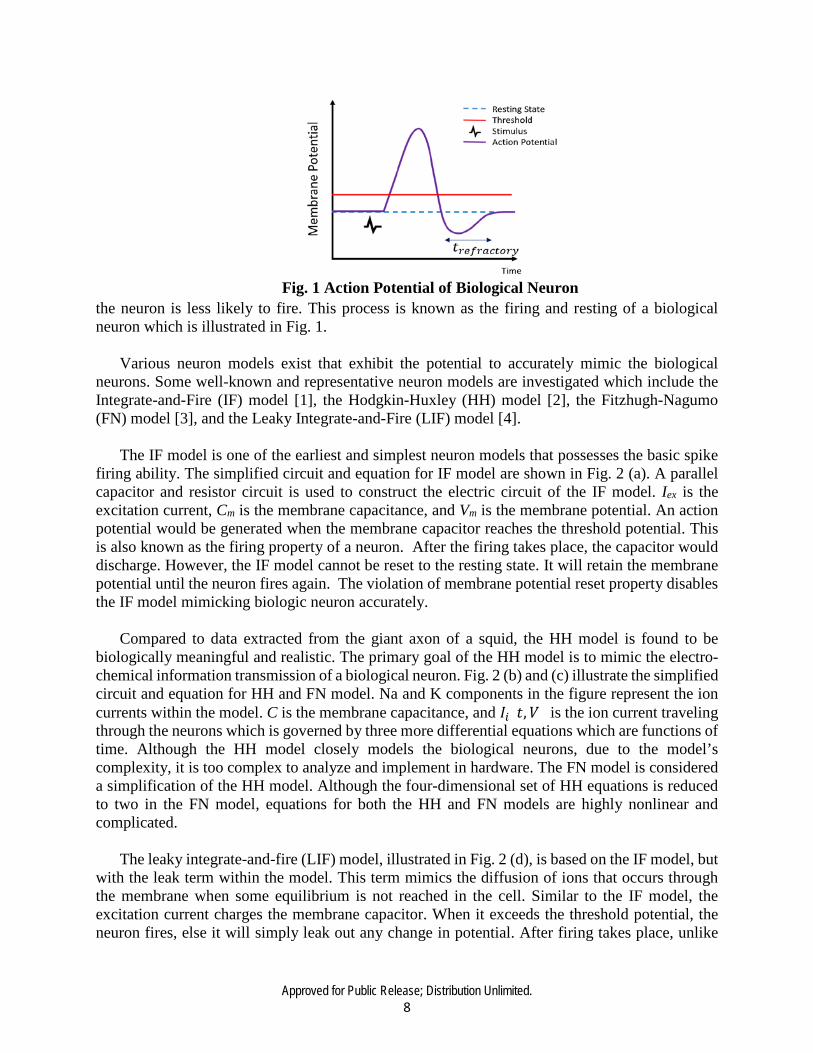
the biological neuron’s behavior. A neuron consists of four main parts: dendrites, soma, axon, and synapse. Signals are collected and transmitted to soma by dendrites. The soma serves as the central processing unit where the nonlinear processing is carried out. When the input exceeds a threshold, an output signal is generated, a so-called “firing stage.” The output is transmitted along the axon, and then to the other neurons through the synapse. In a biological neuron, the signals are in the form of a nerve impulse, called action potentials or spikes. When the stimulus reaches the threshold potential, an action potential is generated. If the threshold is not reached, the membrane potential will leak out. The depolarization and repolarization relate to the movement of sodium and potassium ions in the cell. After the firing, the neuron will go through a refractory period where
Approved for Public Release; Distribution Unlimited. 8
the neuron is less likely to fire. This process is known as the firing and resting of a biological neuron which is illustrated in Fig. 1.
Various neuron models exist that exhibit the potential to accurately mimic the biological
neurons. Some well-known and representative neuron models are investigated which include the Integrate-and-Fire (IF) model [1], the Hodgkin-Huxley (HH) model [2], the Fitzhugh-Nagumo (FN) model [3], and the Leaky Integrate-and-Fire (LIF) model [4].
The IF model is one of the earliest and simplest neuron models that possesses the basic spike
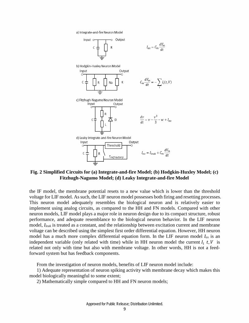
firing ability. The simplified circuit and equation for IF model are shown in Fig. 2 (a). A parallel capacitor and resistor circuit is used to construct the electric circuit of the IF model. Iex is the excitation current, Cm is the membrane capacitance, and Vm is the membrane potential. An action potential would be generated when the membrane capacitor reaches the threshold potential. This is also known as the firing property of a neuron. After the firing takes place, the capacitor would discharge. However, the IF model cannot be reset to the resting state. It will retain the membrane potential until the neuron fires again. The violation of membrane potential reset property disables the IF model mimicking biologic neuron accurately.
Compared to data extracted from the giant axon of a squid, the HH model is found to be
biologically meaningful and realistic. The primary goal of the HH model is to mimic the electro-chemical information transmission of a biological neuron. Fig. 2 (b) and (c) illustrate the simplified circuit and equation for HH and FN model. Na and K components in the figure represent the ion currents within the model. C is the membrane capacitance, and 𝐼𝐼𝑖𝑖(𝑡𝑡,𝑉𝑉) is the ion current traveling through the neurons which is governed by three more differential equations which are functions of time. Although the HH model closely models the biological neurons, due to the model’s complexity, it is too complex to analyze and implement in hardware. The FN model is considered a simplification of the HH model. Although the four-dimensional set of HH equations is reduced to two in the FN model, equations for both the HH and FN models are highly nonlinear and complicated.
The leaky integrate-and-fire (LIF) model, illustrated in Fig. 2 (d), is based on the IF model, but
with the leak term within the model. This term mimics the diffusion of ions that occurs through the membrane when some equilibrium is not reached in the cell. Similar to the IF model, the excitation current charges the membrane capacitor. When it exceeds the threshold potential, the neuron fires, else it will simply leak out any change in potential. After firing takes place, unlike
Fig. 1 Action Potential of Biological Neuron
Approved for Public Release; Distribution Unlimited. 9
the IF model, the membrane potential resets to a new value which is lower than the threshold voltage for LIF model. As such, the LIF neuron model possesses both firing and resetting processes. This neuron model adequately resembles the biological neuron and is relatively easier to implement using analog circuits, as compared to the HH and FN models. Compared with other neuron models, LIF model plays a major role in neuron design due to its compact structure, robust performance, and adequate resemblance to the biological neuron behavior. In the LIF neuron model, Ileak is treated as a constant, and the relationship between excitation current and membrane voltage can be described using the simplest first order differential equation. However, HH neuron model has a much more complex differential equation form. In the LIF neuron model Iex is an independent variable (only related with time) while in HH neuron model the current 𝐼𝐼𝑖𝑖(𝑡𝑡,𝑉𝑉) is related not only with time but also with membrane voltage. In other words, HH is not a feed-forward system but has feedback components.
From the investigation of neuron models, benefits of LIF neuron model include: 1) Adequate representation of neuron spiking activity with membrane decay which makes this
model biologically meaningful to some extent; 2) Mathematically simple compared to HH and FN neuron models;
Fig. 2 Simplified Circuits for (a) Integrate-and-fire Model; (b) Hodgkin-Huxley Model; (c)
Fitzhugh-Nagumo Model; (d) Leaky Integrate-and-fire Model

Approved for Public Release; Distribution Unlimited. 10
3) Since this neuron model possesses relatively simple structure, it is easier to be implemented in hardware. LIF neuron model is extensively employed in the state-of-art neuromorphic chips. IBM’s neurosynaptic core consists of 256 LIF neurons. In the BrainScaleS project, LIF neuron model is also adapted.
After this comprehensive investigation of neuron models and their implementations in
hardware, analog LIF neuron models were employed in our proposed neural encoder design. In the LIF based analog neuron, there are several key parameters, excitation current Iex, threshold voltage Vth, membrane capacitance Cm, and leakage current Ileak, that need to be carefully designed and analyzed. The relationship correlating these parameters is expressed as
𝐼𝐼𝑒𝑒𝑒𝑒 = 𝐼𝐼𝑙𝑙𝑒𝑒𝑙𝑙𝑙𝑙 + 𝐶𝐶𝑚𝑚𝑑𝑑𝑉𝑉𝑚𝑚𝑚𝑚𝑚𝑚𝑑𝑑𝑑𝑑
, (1) where Vmem represents membrane potential. In equation (1), the membrane potential is controlled by the excitation current and the leakage current, and vice versa. A simple resistor model is adapted to represent such relationship. Equation (1) can then be rewritten as the following,
𝐼𝐼𝑒𝑒𝑒𝑒 = 𝑉𝑉𝑚𝑚𝑚𝑚𝑚𝑚𝑅𝑅𝑙𝑙𝑚𝑚𝑙𝑙𝑙𝑙
+ 𝐶𝐶𝑚𝑚𝑑𝑑𝑉𝑉𝑚𝑚𝑚𝑚𝑚𝑚𝑑𝑑𝑑𝑑
, (2) where Rleak defines the weight resistor of leakage current. By solving equation (2), the expression for the membrane potential can now be determined,
𝑉𝑉𝑚𝑚𝑒𝑒𝑚𝑚 = 𝐼𝐼𝑒𝑒𝑒𝑒𝑅𝑅𝑙𝑙𝑒𝑒𝑙𝑙𝑙𝑙 − 𝑒𝑒𝑡𝑡
𝑅𝑅𝐶𝐶𝑚𝑚 (3) When the membrane potential reaches the firing threshold voltage Vth, this membrane potential
will reset to a new value which is lower than Vth. Such dynamic behavior is the firing and resetting process of LIF model. In our design, LIF model serves as the fundamental unit to ensure that the proposed encoder works stably and robustly.
Typically, there are two types of implementations: analog and digital. Digital designs, as the most commonly used and developed, offer the usual digital advantages: noise immunity, ease of implementation, high density and mature manufacturing processes. However, in order to ensure the real-time operation, the digital signals are required to interface with the analog world which leads to the addition of digital-to-analog and analog-to-digital converters. Hence, when implementing some neural operations, such as multiplications, digital designs cannot achieve as small and simple structures as their analog counterparts. Analog implementation has the advantage of implicit real-time operation, resulting in smaller design area and lower power consumption. The total area of the 1 million neuron analog learning system is about 14 times smaller than that of the digital implementation at the 10 nm node [5]. Furthermore, since the analog neuron does not
Fig. 3 Output Spike Train of LIF Neuron Model
Approved for Public Release; Distribution Unlimited. 11
require the signal to noise ratio (SNR) to be as high as the digital one, analog implementation was found to be approximately 20 times more energy efficient [5]. Most importantly, as the behavior of analog neuron is closer to the biological one, the analog implementation seems to be the logical choice for neuromorphic computing emulating the biological neural networks to a better extent. Fig. 3 illustrates the analog output spike trains of LIF neuron model. 3.1.2 ENCODING METHODS
In order to understand how the brain processes information, it is essential to discover the format of neural codes and how they relate to the sensory information. This requires a multidisciplinary approach involving psychophysics, neuroscience, et cetera.
Neural encoders transform sensory information into spikes. Research of the neural code format
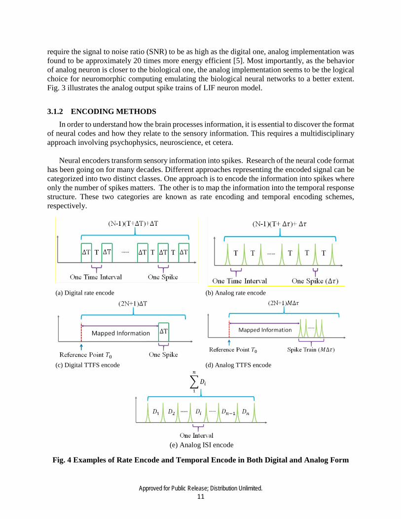
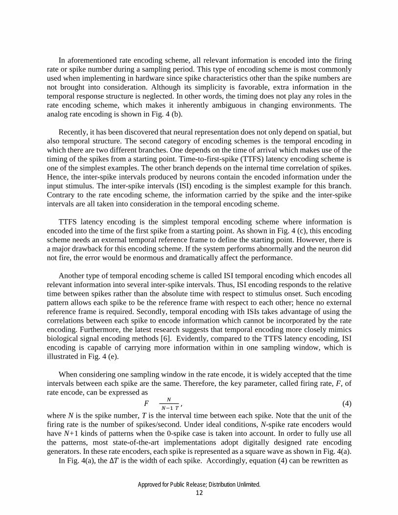
has been going on for many decades. Different approaches representing the encoded signal can be categorized into two distinct classes. One approach is to encode the information into spikes where only the number of spikes matters. The other is to map the information into the temporal response structure. These two categories are known as rate encoding and temporal encoding schemes, respectively.
(a) Digital rate encode (b) Analog rate encode
(c) Digital TTFS encode (d) Analog TTFS encode
(e) Analog ISI encode
Fig. 4 Examples of Rate Encode and Temporal Encode in Both Digital and Analog Form
Approved for Public Release; Distribution Unlimited. 12
In aforementioned rate encoding scheme, all relevant information is encoded into the firing
rate or spike number during a sampling period. This type of encoding scheme is most commonly used when implementing in hardware since spike characteristics other than the spike numbers are not brought into consideration. Although its simplicity is favorable, extra information in the temporal response structure is neglected. In other words, the timing does not play any roles in the rate encoding scheme, which makes it inherently ambiguous in changing environments. The analog rate encoding is shown in Fig. 4 (b).
Recently, it has been discovered that neural representation does not only depend on spatial, but
also temporal structure. The second category of encoding schemes is the temporal encoding in which there are two different branches. One depends on the time of arrival which makes use of the timing of the spikes from a starting point. Time-to-first-spike (TTFS) latency encoding scheme is one of the simplest examples. The other branch depends on the internal time correlation of spikes. Hence, the inter-spike intervals produced by neurons contain the encoded information under the input stimulus. The inter-spike intervals (ISI) encoding is the simplest example for this branch. Contrary to the rate encoding scheme, the information carried by the spike and the inter-spike intervals are all taken into consideration in the temporal encoding scheme.
TTFS latency encoding is the simplest temporal encoding scheme where information is
encoded into the time of the first spike from a starting point. As shown in Fig. 4 (c), this encoding scheme needs an external temporal reference frame to define the starting point. However, there is a major drawback for this encoding scheme. If the system performs abnormally and the neuron did not fire, the error would be enormous and dramatically affect the performance.
Another type of temporal encoding scheme is called ISI temporal encoding which encodes all
relevant information into several inter-spike intervals. Thus, ISI encoding responds to the relative time between spikes rather than the absolute time with respect to stimulus onset. Such encoding pattern allows each spike to be the reference frame with respect to each other; hence no external reference frame is required. Secondly, temporal encoding with ISIs takes advantage of using the correlations between each spike to encode information which cannot be incorporated by the rate encoding. Furthermore, the latest research suggests that temporal encoding more closely mimics biological signal encoding methods [6]. Evidently, compared to the TTFS latency encoding, ISI encoding is capable of carrying more information within in one sampling window, which is illustrated in Fig. 4 (e).
When considering one sampling window in the rate encode, it is widely accepted that the time
intervals between each spike are the same. Therefore, the key parameter, called firing rate, F, of rate encode, can be expressed as
𝐹𝐹 = 𝑁𝑁(𝑁𝑁−1)𝑇𝑇
, (4) where N is the spike number, T is the interval time between each spike. Note that the unit of the firing rate is the number of spikes/second. Under ideal conditions, N-spike rate encoders would have N+1 kinds of patterns when the 0-spike case is taken into account. In order to fully use all the patterns, most state-of-the-art implementations adopt digitally designed rate encoding generators. In these rate encoders, each spike is represented as a square wave as shown in Fig. 4(a).
In Fig. 4(a), the ∆𝑇𝑇 is the width of each spike. Accordingly, equation (4) can be rewritten as

Approved for Public Release; Distribution Unlimited. 13
𝐹𝐹𝑑𝑑𝑖𝑖𝑑𝑑𝑖𝑖𝑑𝑑𝑙𝑙𝑙𝑙 = 𝑁𝑁(𝑁𝑁−1)(𝑇𝑇+∆T)+∆T
. (5) The firing rate decreases in equation (5), leading to fewer pattern variations within one constant
time period. Analog implementation of rate encoding is illustrated in Fig. 4(b). As shown therein, analog rate encoding can handle smaller spike widths, and, as a result, the firing rate can be expressed as
𝐹𝐹𝑙𝑙𝑎𝑎𝑙𝑙𝑙𝑙𝑎𝑎𝑑𝑑 = 𝑁𝑁(𝑁𝑁−1)(𝑇𝑇+∆τ)+∆τ
, (6) where ∆𝜏𝜏 is one spike width. It is clear that 𝐹𝐹𝑙𝑙𝑎𝑎𝑙𝑙𝑙𝑙𝑎𝑎𝑑𝑑 > 𝐹𝐹𝑑𝑑𝑖𝑖𝑑𝑑𝑖𝑖𝑑𝑑𝑙𝑙𝑙𝑙 , since ∆𝜏𝜏 < ∆𝑇𝑇 when other conditions are the same. However, error rate would become very large when the smallest resolution is adopted in the analog rate encoder. Therefore, various techniques for decreasing resolution must be applied to attain an acceptable error rate as compared to its corresponding digital implementation.
In TTFS encoding, when the same spike width is adopted as in rate encoding, the total number of patterns for such kind of data format is 2𝑁𝑁 + 1. The minimum resolution of TTFS encode can be assumed as the spike width ∆𝑇𝑇 without loss of generality. The time interval from reference point to the first spike can be expressed as
𝑇𝑇𝑇𝑇𝑇𝑇𝑇𝑇𝑇𝑇 = 𝑇𝑇1−𝑇𝑇0∆𝑇𝑇
, (7) where 𝑇𝑇1 represent the first spike’s appearing time point. Although an analog implementation of TTFS may generate more patterns than that of the digital implementation within the same time period, it suffers from high error rate if the minimum resolution is adopted. A balance is made by using a small spike train to substitute only one spike, which is illustrated in Fig. 4(d). The spike train must obey the constraint rule
𝑀𝑀∆𝜏𝜏 = ∆𝑇𝑇, (8) where 𝑀𝑀 is the spike number and ∆𝜏𝜏 is one spike width.
As shown in Fig. 4(e), 𝑛𝑛 + 1 spikes can build an 𝑛𝑛 − 𝑖𝑖𝑛𝑛𝑡𝑡𝑒𝑒𝑖𝑖𝑖𝑖𝑖𝑖𝑖𝑖 ISI encoder. In the analog
implementation, only spike intervals are taken into account. In the ideal case, each interval is independent of each other which can generate infinite types of patterns. This property of ISI encode can be described as
𝑐𝑐𝑐𝑐𝑖𝑖(𝐷𝐷1,𝐷𝐷2, … ,𝐷𝐷𝑎𝑎) = 0, (9) where 𝑐𝑐𝑐𝑐𝑖𝑖() represents the correlation operation. As shown in Fig. 4, the total number of patterns is much larger than the TTFS and rate encoders even if we take the resolution and error rate into consideration. Therefore, the ISI encoder is one of the best encoding schemes for spiking neural networks. However, it is very complex and challenging to implement this kind of infinite-pattern ISI encoder in hardware. In order to reduce the implementation complexity, we proposed a finite pattern ISI (FPISI) encoding format applicable for analog hardware implementation. In such an FPISI encoder, the correlation between each interval is not 0 anymore. The simplest case relates later intervals to previous ones; implementation of temporal encoding was first suggested in [6]. All of the approaches used TTFS latency encoding.
Approved for Public Release; Distribution Unlimited. 14
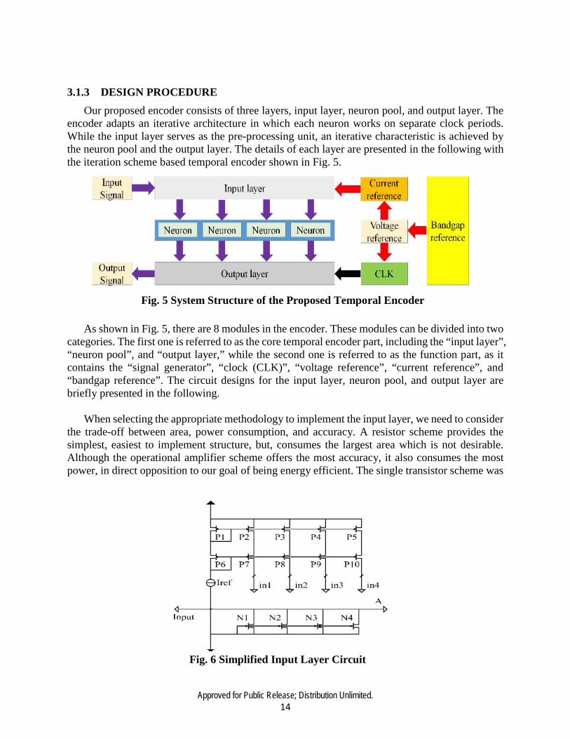
3.1.3 DESIGN PROCEDURE Our proposed encoder consists of three layers, input layer, neuron pool, and output layer. The
encoder adapts an iterative architecture in which each neuron works on separate clock periods. While the input layer serves as the pre-processing unit, an iterative characteristic is achieved by the neuron pool and the output layer. The details of each layer are presented in the following with the iteration scheme based temporal encoder shown in Fig. 5.
As shown in Fig. 5, there are 8 modules in the encoder. These modules can be divided into two
categories. The first one is referred to as the core temporal encoder part, including the “input layer”, “neuron pool”, and “output layer,” while the second one is referred to as the function part, as it contains the “signal generator”, “clock (CLK)”, “voltage reference”, “current reference”, and “bandgap reference”. The circuit designs for the input layer, neuron pool, and output layer are briefly presented in the following.
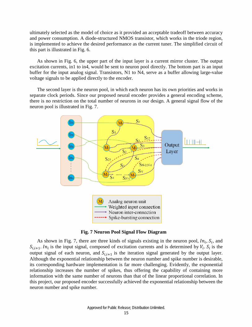
When selecting the appropriate methodology to implement the input layer, we need to consider
the trade-off between area, power consumption, and accuracy. A resistor scheme provides the simplest, easiest to implement structure, but, consumes the largest area which is not desirable. Although the operational amplifier scheme offers the most accuracy, it also consumes the most power, in direct opposition to our goal of being energy efficient. The single transistor scheme was
Fig. 5 System Structure of the Proposed Temporal Encoder
Fig. 6 Simplified Input Layer Circuit
Approved for Public Release; Distribution Unlimited. 15
ultimately selected as the model of choice as it provided an acceptable tradeoff between accuracy and power consumption. A diode-structured NMOS transistor, which works in the triode region, is implemented to achieve the desired performance as the current tuner. The simplified circuit of this part is illustrated in Fig. 6.
As shown in Fig. 6, the upper part of the input layer is a current mirror cluster. The output
excitation currents, in1 to in4, would be sent to neuron pool directly. The bottom part is an input buffer for the input analog signal. Transistors, N1 to N4, serve as a buffer allowing large-value voltage signals to be applied directly to the encoder.
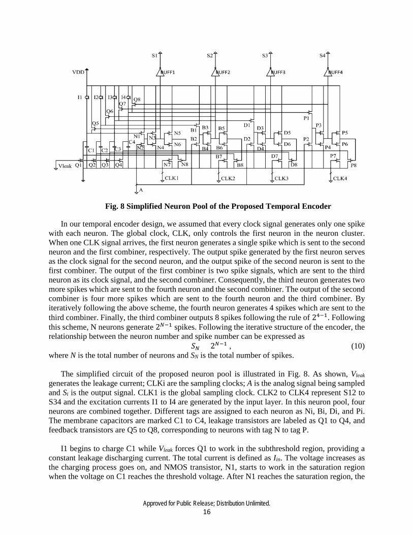
The second layer is the neuron pool, in which each neuron has its own priorities and works in
separate clock periods. Since our proposed neural encoder provides a general encoding scheme, there is no restriction on the total number of neurons in our design. A general signal flow of the neuron pool is illustrated in Fig. 7.
As shown in Fig. 7, there are three kinds of signals existing in the neuron pool, 𝐼𝐼𝑛𝑛𝑖𝑖, 𝑆𝑆𝑖𝑖, and 𝑆𝑆𝑖𝑖,𝑖𝑖+1. 𝐼𝐼𝑛𝑛𝑖𝑖 is the input signal, composed of excitation currents and is determined by 𝑉𝑉𝑖𝑖. 𝑆𝑆𝑖𝑖 is the output signal of each neuron, and 𝑆𝑆𝑖𝑖,𝑖𝑖+1 is the iteration signal generated by the output layer. Although the exponential relationship between the neuron number and spike number is desirable, its corresponding hardware implementation is far more challenging. Evidently, the exponential relationship increases the number of spikes, thus offering the capability of containing more information with the same number of neurons than that of the linear proportional correlation. In this project, our proposed encoder successfully achieved the exponential relationship between the neuron number and spike number.
Fig. 7 Neuron Pool Signal Flow Diagram
Approved for Public Release; Distribution Unlimited. 16
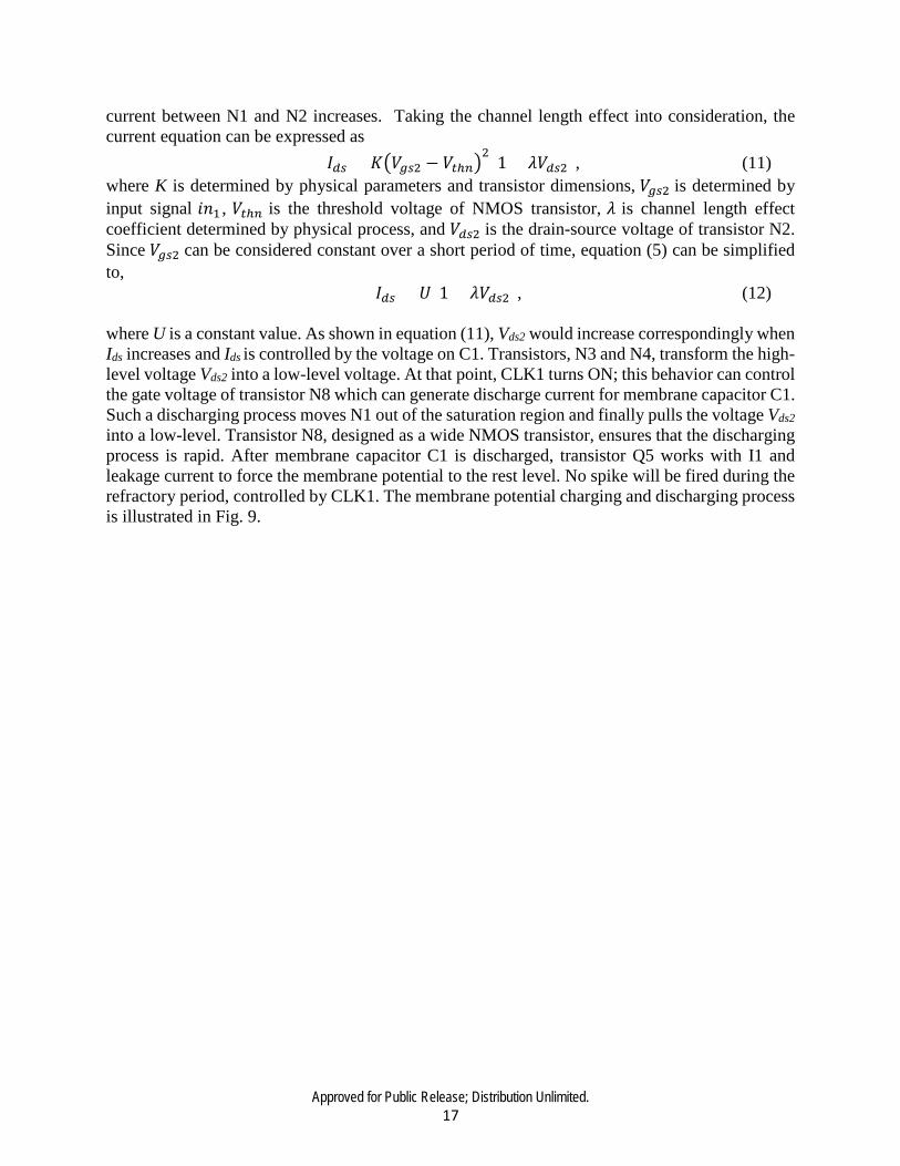
In our temporal encoder design, we assumed that every clock signal generates only one spike with each neuron. The global clock, CLK, only controls the first neuron in the neuron cluster. When one CLK signal arrives, the first neuron generates a single spike which is sent to the second neuron and the first combiner, respectively. The output spike generated by the first neuron serves as the clock signal for the second neuron, and the output spike of the second neuron is sent to the first combiner. The output of the first combiner is two spike signals, which are sent to the third neuron as its clock signal, and the second combiner. Consequently, the third neuron generates two more spikes which are sent to the fourth neuron and the second combiner. The output of the second combiner is four more spikes which are sent to the fourth neuron and the third combiner. By iteratively following the above scheme, the fourth neuron generates 4 spikes which are sent to the third combiner. Finally, the third combiner outputs 8 spikes following the rule of 24−1. Following this scheme, N neurons generate 2𝑁𝑁−1 spikes. Following the iterative structure of the encoder, the relationship between the neuron number and spike number can be expressed as
𝑆𝑆𝑁𝑁 = 2𝑁𝑁−1 , (10) where N is the total number of neurons and SN is the total number of spikes.
The simplified circuit of the proposed neuron pool is illustrated in Fig. 8. As shown, Vleak generates the leakage current; CLKi are the sampling clocks; A is the analog signal being sampled and Si is the output signal. CLK1 is the global sampling clock. CLK2 to CLK4 represent S12 to S34 and the excitation currents I1 to I4 are generated by the input layer. In this neuron pool, four neurons are combined together. Different tags are assigned to each neuron as Ni, Bi, Di, and Pi. The membrane capacitors are marked C1 to C4, leakage transistors are labeled as Q1 to Q4, and feedback transistors are Q5 to Q8, corresponding to neurons with tag N to tag P.
I1 begins to charge C1 while Vleak forces Q1 to work in the subthreshold region, providing a
constant leakage discharging current. The total current is defined as Iin. The voltage increases as the charging process goes on, and NMOS transistor, N1, starts to work in the saturation region when the voltage on C1 reaches the threshold voltage. After N1 reaches the saturation region, the
Fig. 8 Simplified Neuron Pool of the Proposed Temporal Encoder
Approved for Public Release; Distribution Unlimited. 17
current between N1 and N2 increases. Taking the channel length effect into consideration, the current equation can be expressed as 𝐼𝐼𝑑𝑑𝑑𝑑 = 𝐾𝐾�𝑉𝑉𝑑𝑑𝑑𝑑2 − 𝑉𝑉𝑑𝑑ℎ𝑎𝑎�
2(1 + 𝜆𝜆𝑉𝑉𝑑𝑑𝑑𝑑2), (11)
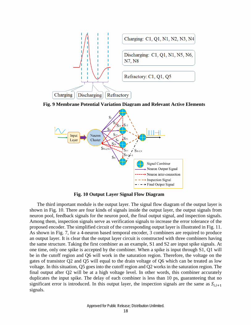
where K is determined by physical parameters and transistor dimensions, 𝑉𝑉𝑑𝑑𝑑𝑑2 is determined by input signal 𝑖𝑖𝑛𝑛1 , 𝑉𝑉𝑑𝑑ℎ𝑎𝑎 is the threshold voltage of NMOS transistor, 𝜆𝜆 is channel length effect coefficient determined by physical process, and 𝑉𝑉𝑑𝑑𝑑𝑑2 is the drain-source voltage of transistor N2. Since 𝑉𝑉𝑑𝑑𝑑𝑑2 can be considered constant over a short period of time, equation (5) can be simplified to, 𝐼𝐼𝑑𝑑𝑑𝑑 = 𝑈𝑈(1 + 𝜆𝜆𝑉𝑉𝑑𝑑𝑑𝑑2), (12) where U is a constant value. As shown in equation (11), Vds2 would increase correspondingly when Ids increases and Ids is controlled by the voltage on C1. Transistors, N3 and N4, transform the high-level voltage Vds2 into a low-level voltage. At that point, CLK1 turns ON; this behavior can control the gate voltage of transistor N8 which can generate discharge current for membrane capacitor C1. Such a discharging process moves N1 out of the saturation region and finally pulls the voltage Vds2 into a low-level. Transistor N8, designed as a wide NMOS transistor, ensures that the discharging process is rapid. After membrane capacitor C1 is discharged, transistor Q5 works with I1 and leakage current to force the membrane potential to the rest level. No spike will be fired during the refractory period, controlled by CLK1. The membrane potential charging and discharging process is illustrated in Fig. 9.
Approved for Public Release; Distribution Unlimited. 18
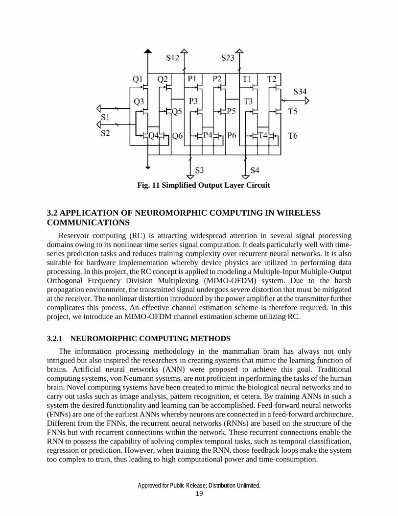
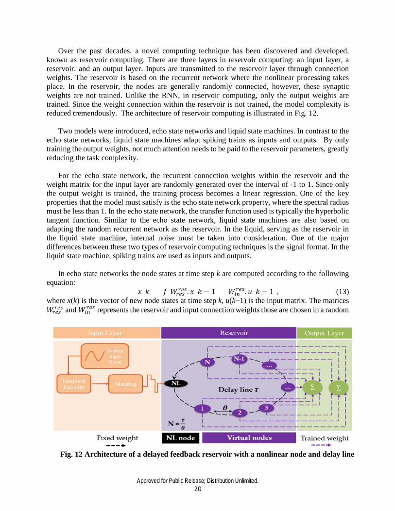
The third important module is the output layer. The signal flow diagram of the output layer is shown in Fig. 10. There are four kinds of signals inside the output layer, the output signals from neuron pool, feedback signals for the neuron pool, the final output signal, and inspection signals. Among them, inspection signals serve as verification signals to increase the error tolerance of the proposed encoder. The simplified circuit of the corresponding output layer is illustrated in Fig. 11. As shown in Fig. 7, for a 4-neuron based temporal encoder, 3 combiners are required to produce an output layer. It is clear that the output layer circuit is constructed with three combiners having the same structure. Taking the first combiner as an example, S1 and S2 are input spike signals. At one time, only one spike is accepted by the combiner. When a spike is input through S1, Q1 will be in the cutoff region and Q6 will work in the saturation region. Therefore, the voltage on the gates of transistor Q2 and Q5 will equal to the drain voltage of Q6 which can be treated as low voltage. In this situation, Q5 goes into the cutoff region and Q2 works in the saturation region. The final output after Q2 will be at a high voltage level. In other words, this combiner accurately duplicates the input spike. The delay of each combiner is less than 10 ps, guaranteeing that no significant error is introduced. In this output layer, the inspection signals are the same as 𝑆𝑆𝑖𝑖,𝑖𝑖+1 signals.
Fig. 9 Membrane Potential Variation Diagram and Relevant Active Elements
Fig. 10 Output Layer Signal Flow Diagram
Approved for Public Release; Distribution Unlimited. 19
3.2 APPLICATION OF NEUROMORPHIC COMPUTING IN WIRELESS COMMUNICATIONS
Reservoir computing (RC) is attracting widespread attention in several signal processing domains owing to its nonlinear time series signal computation. It deals particularly well with time-series prediction tasks and reduces training complexity over recurrent neural networks. It is also suitable for hardware implementation whereby device physics are utilized in performing data processing. In this project, the RC concept is applied to modeling a Multiple-Input Multiple-Output Orthogonal Frequency Division Multiplexing (MIMO-OFDM) system. Due to the harsh propagation environment, the transmitted signal undergoes severe distortion that must be mitigated at the receiver. The nonlinear distortion introduced by the power amplifier at the transmitter further complicates this process. An effective channel estimation scheme is therefore required. In this project, we introduce an MIMO-OFDM channel estimation scheme utilizing RC.
3.2.1 NEUROMORPHIC COMPUTING METHODS The information processing methodology in the mammalian brain has always not only
intrigued but also inspired the researchers in creating systems that mimic the learning function of brains. Artificial neural networks (ANN) were proposed to achieve this goal. Traditional computing systems, von Neumann systems, are not proficient in performing the tasks of the human brain. Novel computing systems have been created to mimic the biological neural networks and to carry out tasks such as image analysis, pattern recognition, et cetera. By training ANNs in such a system the desired functionality and learning can be accomplished. Feed-forward neural networks (FNNs) are one of the earliest ANNs whereby neurons are connected in a feed-forward architecture. Different from the FNNs, the recurrent neural networks (RNNs) are based on the structure of the FNNs but with recurrent connections within the network. These recurrent connections enable the RNN to possess the capability of solving complex temporal tasks, such as temporal classification, regression or prediction. However, when training the RNN, those feedback loops make the system too complex to train, thus leading to high computational power and time-consumption.
Fig. 11 Simplified Output Layer Circuit
Approved for Public Release; Distribution Unlimited. 20
Over the past decades, a novel computing technique has been discovered and developed, known as reservoir computing. There are three layers in reservoir computing: an input layer, a reservoir, and an output layer. Inputs are transmitted to the reservoir layer through connection weights. The reservoir is based on the recurrent network where the nonlinear processing takes place. In the reservoir, the nodes are generally randomly connected, however, these synaptic weights are not trained. Unlike the RNN, in reservoir computing, only the output weights are trained. Since the weight connection within the reservoir is not trained, the model complexity is reduced tremendously. The architecture of reservoir computing is illustrated in Fig. 12.
Two models were introduced, echo state networks and liquid state machines. In contrast to the
echo state networks, liquid state machines adapt spiking trains as inputs and outputs. By only training the output weights, not much attention needs to be paid to the reservoir parameters, greatly reducing the task complexity.
For the echo state network, the recurrent connection weights within the reservoir and the
weight matrix for the input layer are randomly generated over the interval of -1 to 1. Since only the output weight is trained, the training process becomes a linear regression. One of the key properties that the model must satisfy is the echo state network property, where the spectral radius must be less than 1. In the echo state network, the transfer function used is typically the hyperbolic tangent function. Similar to the echo state network, liquid state machines are also based on adapting the random recurrent network as the reservoir. In the liquid, serving as the reservoir in the liquid state machine, internal noise must be taken into consideration. One of the major differences between these two types of reservoir computing techniques is the signal format. In the liquid state machine, spiking trains are used as inputs and outputs.
In echo state networks the node states at time step k are computed according to the following
equation: 𝑥𝑥(𝑘𝑘) = 𝑓𝑓[𝑊𝑊𝑟𝑟𝑒𝑒𝑑𝑑
𝑟𝑟𝑒𝑒𝑑𝑑. 𝑥𝑥(𝑘𝑘 − 1) + 𝑊𝑊𝑖𝑖𝑎𝑎𝑟𝑟𝑒𝑒𝑑𝑑.𝑢𝑢(𝑘𝑘 − 1), (13)
where x(k) is the vector of new node states at time step k, u(k−1) is the input matrix. The matrices 𝑊𝑊𝑟𝑟𝑒𝑒𝑑𝑑
𝑟𝑟𝑒𝑒𝑑𝑑 and 𝑊𝑊𝑖𝑖𝑎𝑎𝑟𝑟𝑒𝑒𝑑𝑑 represents the reservoir and input connection weights those are chosen in a random
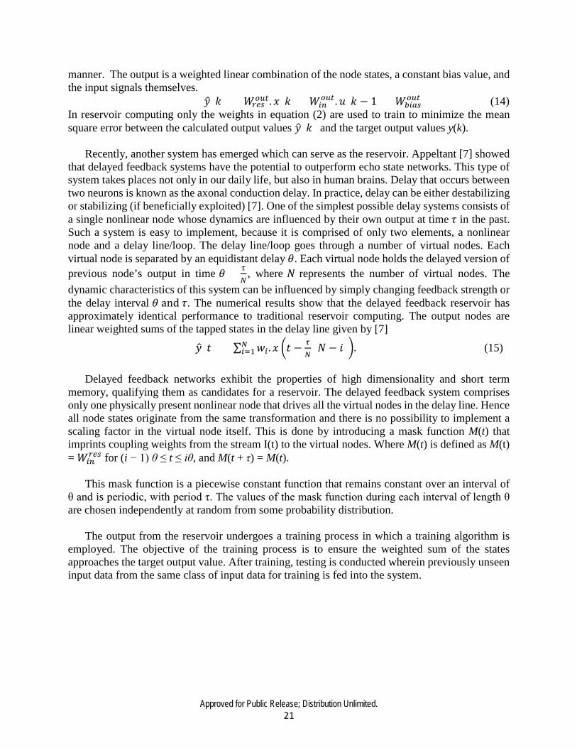
Fig. 12 Architecture of a delayed feedback reservoir with a nonlinear node and delay line
Approved for Public Release; Distribution Unlimited. 21
manner. The output is a weighted linear combination of the node states, a constant bias value, and the input signals themselves.
𝑦𝑦�(𝑘𝑘) = 𝑊𝑊𝑟𝑟𝑒𝑒𝑑𝑑𝑎𝑎𝑜𝑜𝑑𝑑. 𝑥𝑥(𝑘𝑘) + 𝑊𝑊𝑖𝑖𝑎𝑎
𝑎𝑎𝑜𝑜𝑑𝑑.𝑢𝑢(𝑘𝑘 − 1) + 𝑊𝑊𝑏𝑏𝑖𝑖𝑙𝑙𝑑𝑑𝑎𝑎𝑜𝑜𝑑𝑑 (14)
In reservoir computing only the weights in equation (2) are used to train to minimize the mean square error between the calculated output values 𝑦𝑦�(𝑘𝑘) and the target output values y(k).
Recently, another system has emerged which can serve as the reservoir. Appeltant [7] showed
that delayed feedback systems have the potential to outperform echo state networks. This type of system takes places not only in our daily life, but also in human brains. Delay that occurs between two neurons is known as the axonal conduction delay. In practice, delay can be either destabilizing or stabilizing (if beneficially exploited) [7]. One of the simplest possible delay systems consists of a single nonlinear node whose dynamics are influenced by their own output at time 𝜏𝜏 in the past. Such a system is easy to implement, because it is comprised of only two elements, a nonlinear node and a delay line/loop. The delay line/loop goes through a number of virtual nodes. Each virtual node is separated by an equidistant delay 𝜃𝜃. Each virtual node holds the delayed version of previous node’s output in time 𝜃𝜃 = 𝜏𝜏
𝑁𝑁, where 𝑁𝑁 represents the number of virtual nodes. The
dynamic characteristics of this system can be influenced by simply changing feedback strength or the delay interval 𝜃𝜃 and 𝜏𝜏. The numerical results show that the delayed feedback reservoir has approximately identical performance to traditional reservoir computing. The output nodes are linear weighted sums of the tapped states in the delay line given by [7]
𝑦𝑦�(𝑡𝑡) = ∑ 𝑤𝑤𝑖𝑖. 𝑥𝑥 �𝑡𝑡 −𝜏𝜏𝑁𝑁
(𝑁𝑁 − 𝑖𝑖)�𝑁𝑁𝑖𝑖=1 . (15)
Delayed feedback networks exhibit the properties of high dimensionality and short term
memory, qualifying them as candidates for a reservoir. The delayed feedback system comprises only one physically present nonlinear node that drives all the virtual nodes in the delay line. Hence all node states originate from the same transformation and there is no possibility to implement a scaling factor in the virtual node itself. This is done by introducing a mask function M(t) that imprints coupling weights from the stream I(t) to the virtual nodes. Where M(t) is defined as M(t) = 𝑊𝑊𝑖𝑖𝑎𝑎
𝑟𝑟𝑒𝑒𝑑𝑑 for (i − 1) θ ≤ t ≤ iθ, and M(t + τ) = M(t). This mask function is a piecewise constant function that remains constant over an interval of
θ and is periodic, with period τ. The values of the mask function during each interval of length θ are chosen independently at random from some probability distribution.
The output from the reservoir undergoes a training process in which a training algorithm is
employed. The objective of the training process is to ensure the weighted sum of the states approaches the target output value. After training, testing is conducted wherein previously unseen input data from the same class of input data for training is fed into the system.

Approved for Public Release; Distribution Unlimited. 22
3.2.2 SYSTEM MODEL AND ASSUMPTIONS Block-structured nonlinear systems: We are particularly interested in the applications of the
nonlinear MIMO-OFDM communication channel which constitutes one of the most important technologies used in current and emerging telecommunication systems. An interesting issue with these systems is that the communication channel can be modeled as block-structured nonlinear systems, i.e. series cascades of nonlinear and linear blocks. A nonlinear MIMO-OFDM system is composed of memoryless nonlinear blocks in parallel, corresponding to the power amplifier (PA), followed by a linear mixer which in a single-input-single-output OFDM system is a linear Finite Impulse Response (FIR) filter corresponding to the frequency selective fading wireless link.
Fig. 13 Discrete-Time Equivalent Baseband OFDM System
OFDM System: We consider a discrete-time equivalent baseband OFDM system (Fig. 13). The time-domain symbols with the cyclic prefix (CP) are then amplified by a PA that is modeled as a Saleh model. It is worth mentioning that when the PA is linear, the cyclic prefix can avoid inter-symbol interference (ISI) and inter-carrier interference (ICI), ensuring the orthogonality between the subcarriers. However, as shown in the sequel, for a nonlinear PA, some ICI is introduced in the received signals, even when a cyclic prefix is used. The effect of the nonlinear amplifier depends on the operating point, which is the average power of the input signals. Input back-off (IBO) and output back-off (OBO) are two common parameters to verify the nonlinear distortion. It is worth noting that due to the presence of PAs, a high PAPR causes the introduction of nonlinear ICI in the received signal if a high input back-off (IBO) is not used; this can significantly deteriorate the recovery of the information symbols. A high IBO results in a low-power efficiency of the PA and a low signal-to-noise ratio (SNR) at the receiver. Moreover, it may limit the battery life for mobile applications.
Approved for Public Release; Distribution Unlimited. 23
3.2.3 RC BASED CHANNEL ESTIMATION SCHEME Inspired by the fact that there is a nonlinear time-varying distortion of the signal whilst
propagating through the wireless channel, RC is applied to time domain channel estimation. In specific, the wireless channel between the transmitter and receiver is a multipath propagation environment that exhibits the properties of time variance and frequency selectivity.
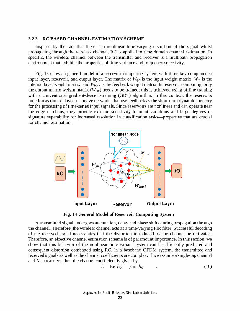
Fig. 14 shows a general model of a reservoir computing system with three key components:
input layer, reservoir, and output layer. The matrix of Wsys is the input weight matrix, Win is the internal layer weight matrix, and Wback is the feedback weight matrix. In reservoir computing, only the output matrix weight matrix (Wout) needs to be trained; this is achieved using offline training with a conventional gradient-descent-training (GDT) algorithm. In this context, the reservoirs function as time-delayed recursive networks that use feedback as the short-term dynamic memory for the processing of time-series input signals. Since reservoirs are nonlinear and can operate near the edge of chaos, they provide extreme sensitivity to input variations and large degrees of signature separability for increased resolution in classification tasks—properties that are crucial for channel estimation.
A transmitted signal undergoes attenuation, delay and phase shifts during propagation through the channel. Therefore, the wireless channel acts as a time-varying FIR filter. Successful decoding of the received signal necessitates that the distortion introduced by the channel be mitigated. Therefore, an effective channel estimation scheme is of paramount importance. In this section, we show that this behavior of the nonlinear time variant system can be efficiently predicted and consequent distortion combatted using RC. In a baseband OFDM system, the transmitted and received signals as well as the channel coefficients are complex. If we assume a single-tap channel and N subcarriers, then the channel coefficient is given by:
ℎ = Re(ℎ0) + 𝑗𝑗Im(ℎ0) . (16)
Fig. 14 General Model of Reservoir Computing System

Approved for Public Release; Distribution Unlimited. 24
Ignoring white noise, the complex time-domain received signal yn is obtained from the complex time-domain input sequence xn by:
Re(𝑦𝑦𝑎𝑎) = Re(𝑥𝑥𝑎𝑎)Re(ℎ0) − Im(𝑥𝑥𝑎𝑎)Im(ℎ0) Im(𝑦𝑦𝑎𝑎) = Re(𝑥𝑥𝑎𝑎)Im(ℎ0) − Im(𝑥𝑥𝑎𝑎)Re(ℎ0) (17)
From (17), it is observed that the real and the imaginary parts of the received signal depend on
both the real and imaginary parts of the transmitted signal and the channel coefficient. However, the RC can only operate on real numbers at its input and output nodes. Therefore, we use an RC scheme with two input and two output nodes. The RC takes as input the complex time-domain received signal with the cyclic prefix added, and outputs an estimate of the complex time domain transmitted signal.
4.0 RESULTS AND DISCUSSION 4.1 PERFORMANCE ANALYSIS OF ANALOG NEURONS
In this section, we show the post layout simulation and measurement results, and robustness and energy efficiency analysis of the proposed temporal encoder. The whole layout view of the encoder chip is illustrated in Fig. 15.
Fig. 15 Whole Layout View of the Encoder Chip
Approved for Public Release; Distribution Unlimited. 25
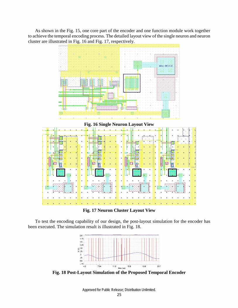
As shown in the Fig. 15, one core part of the encoder and one function module work together to achieve the temporal encoding process. The detailed layout view of the single neuron and neuron cluster are illustrated in Fig. 16 and Fig. 17, respectively.
Fig. 16 Single Neuron Layout View
Fig. 17 Neuron Cluster Layout View To test the encoding capability of our design, the post-layout simulation for the encoder has
been executed. The simulation result is illustrated in Fig. 18.
Fig. 18 Post-Layout Simulation of the Proposed Temporal Encoder
Approved for Public Release; Distribution Unlimited. 26
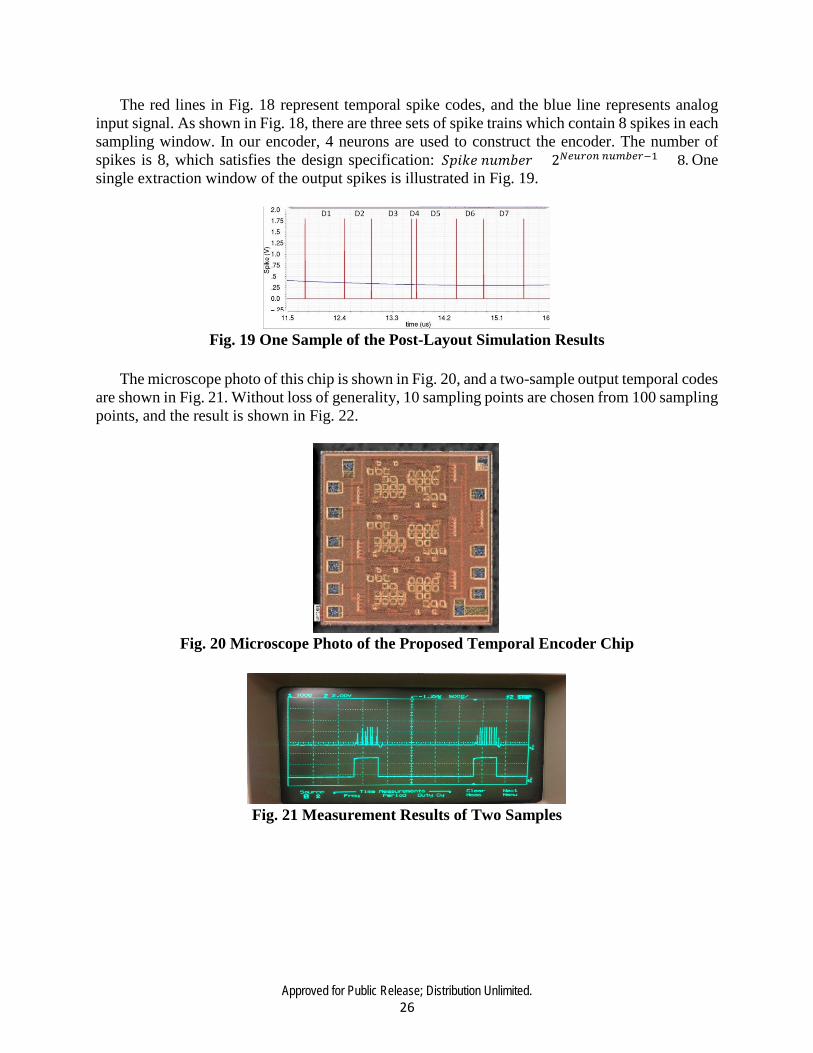
The red lines in Fig. 18 represent temporal spike codes, and the blue line represents analog input signal. As shown in Fig. 18, there are three sets of spike trains which contain 8 spikes in each sampling window. In our encoder, 4 neurons are used to construct the encoder. The number of spikes is 8, which satisfies the design specification: 𝑆𝑆𝑆𝑆𝑖𝑖𝑘𝑘𝑒𝑒 𝑛𝑛𝑢𝑢𝑛𝑛𝑛𝑛𝑒𝑒𝑖𝑖 = 2𝑁𝑁𝑒𝑒𝑜𝑜𝑟𝑟𝑎𝑎𝑎𝑎 𝑎𝑎𝑜𝑜𝑚𝑚𝑏𝑏𝑒𝑒𝑟𝑟−1 = 8. One single extraction window of the output spikes is illustrated in Fig. 19.
Fig. 19 One Sample of the Post-Layout Simulation Results
The microscope photo of this chip is shown in Fig. 20, and a two-sample output temporal codes
are shown in Fig. 21. Without loss of generality, 10 sampling points are chosen from 100 sampling points, and the result is shown in Fig. 22.
Fig. 20 Microscope Photo of the Proposed Temporal Encoder Chip
Fig. 21 Measurement Results of Two Samples
Approved for Public Release; Distribution Unlimited. 27
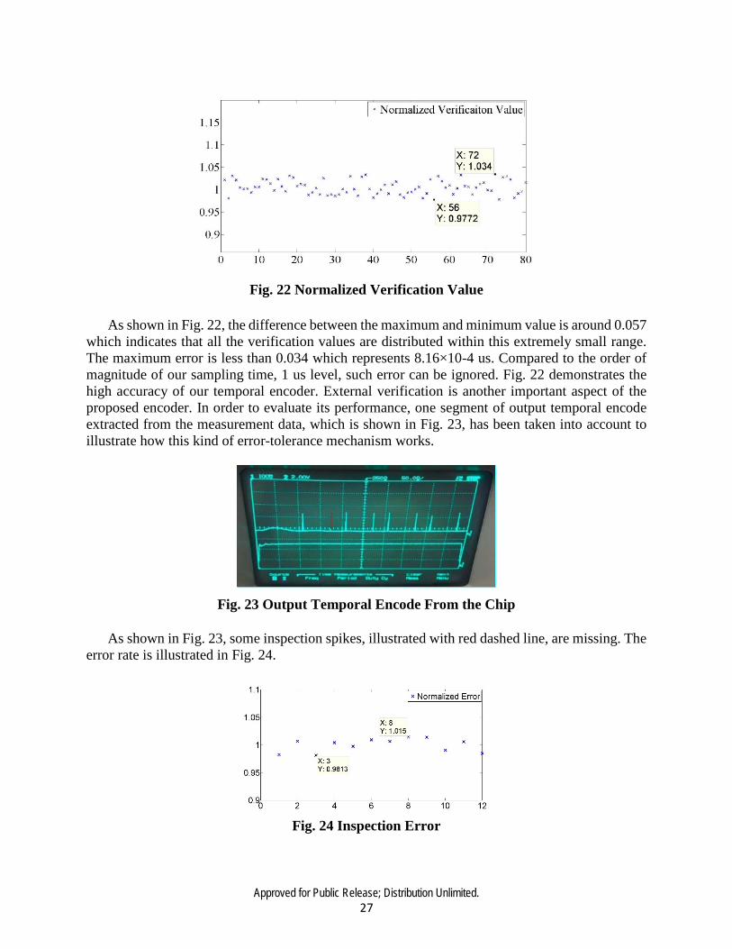
Fig. 22 Normalized Verification Value
As shown in Fig. 22, the difference between the maximum and minimum value is around 0.057 which indicates that all the verification values are distributed within this extremely small range. The maximum error is less than 0.034 which represents 8.16×10⁻⁴ us. Compared to the order of magnitude of our sampling time, 1 us level, such error can be ignored. Fig. 22 demonstrates the high accuracy of our temporal encoder. External verification is another important aspect of the proposed encoder. In order to evaluate its performance, one segment of output temporal encode extracted from the measurement data, which is shown in Fig. 23, has been taken into account to illustrate how this kind of error-tolerance mechanism works.
Fig. 23 Output Temporal Encode From the Chip As shown in Fig. 23, some inspection spikes, illustrated with red dashed line, are missing. The
error rate is illustrated in Fig. 24.
Fig. 24 Inspection Error

Approved for Public Release; Distribution Unlimited. 28
As shown in Fig. 24, the difference between the maximum value and the minimum value is around 0.022 us. This is much smaller than the minimum resolution of each single temporal encoding of 0.1 us.
4.2 PERFOMANCE EVALUATION AND DISCUSSION OF RC-BASED CHANNEL ESTIMATION
In this section, we will present the simulation results for the proposed RC-based channel estimator. We consider a block-fading channel model for the MIMO-OFDM system, in which an independent channel realization occurs for every 19 OFDM symbols. In the construction of the nonlinear block-fading channel model, the nonlinear power amplifier model was incorporated into the channel model. We assume that the parameters of the nonlinear power amplifier are the same across all transmit antennas in the MIMO-OFDM system.
The bandwidth of the OFDM system simulated was set at 2.05 MHz, the Doppler frequency
was set at 100 Hz. For the wireless channel, the channel impulse response length was considered to be 8. A 512-pt FFT was used over a total of 1000 OFDM transmitted symbols, where for 19 OFDM symbols, the channel was considered unchanged. 16-QAM modulation scheme was employed and the parameters for the nonlinear power amplifier, i.e., Clip Level and Shape parameter, were set at 3dB and 1, respectively.
We use the bit error rate (BER) as a performance measure for measuring the effectiveness of
our approach. Two sets of simulations were performed. At first, the BER was simulated for different number of neurons in the reservoir in order to find out a suitable value of the reservoir size. Using this value, we proceed to simulate the BER for different SNR values. The connectivity of the reservoir, which refers to the number of non-zero entries in the internal weight matrix W, and the spectral radius were set at 20% and 0.98, respectively.
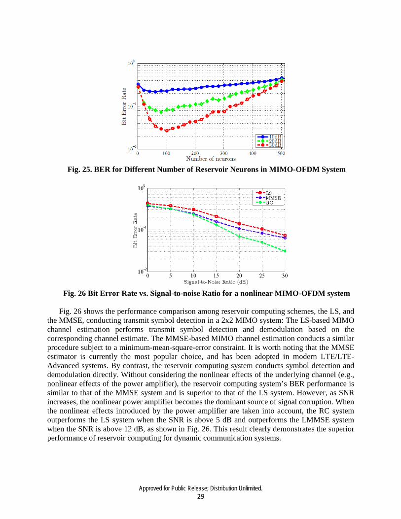
We analyzed the effect on the BER of the MIMO-OFDM systems while increasing the number
of reservoir neurons in increments of 20, starting with 2 neurons, for three different SNR values: 10 dB, 20 dB and 30 dB. The expected trend is that as the number of neurons increases, the performance of the RC should increase and hence a lower BER should be observed. With the increase of the number of neurons, a higher dimensionality is available for resolving the inputs as more neurons are available for the per-input-sample for the same dimensions of the input. Fig. 25 shows the BER curves for the nonlinear MIMO-OFDM system. For this system a convex shaped curve is obtained, with a minimum BER occurring in the approximate region of 50 to 100 neurons. Fig. 25 illustrates that by increasing SNR value, the magnitude of the minimum BER decreases. However, the value of the minimum BER falls in the range from 50 to 100 neurons. The results make intuitive sense, since, as we have simulated an OFDM system with 512 subcarriers and used a reservoir with 20% connectivity, the number of non-sparse connections is around 500 when there are around 50 neurons in the reservoir. In this condition, each of the 512 orthogonal subcarriers can be independently resolved by the reservoir in the projection space. If there are lower than 50 neurons, there is an inadequate number of reservoir connections compared to the number of subcarriers and hence they cannot be independently resolved. When there are more than 50 neurons, a single subcarrier can be resolved into more than one dimension in the projection space, resulting in redundancy, which in effect increases BER.
Approved for Public Release; Distribution Unlimited. 29
Fig. 25. BER for Different Number of Reservoir Neurons in MIMO-OFDM System
Fig. 26 Bit Error Rate vs. Signal-to-noise Ratio for a nonlinear MIMO-OFDM system
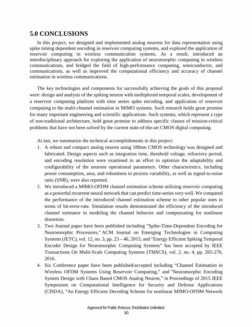
Fig. 26 shows the performance comparison among reservoir computing schemes, the LS, and
the MMSE, conducting transmit symbol detection in a 2x2 MIMO system: The LS-based MIMO channel estimation performs transmit symbol detection and demodulation based on the corresponding channel estimate. The MMSE-based MIMO channel estimation conducts a similar procedure subject to a minimum-mean-square-error constraint. It is worth noting that the MMSE estimator is currently the most popular choice, and has been adopted in modern LTE/LTE-Advanced systems. By contrast, the reservoir computing system conducts symbol detection and demodulation directly. Without considering the nonlinear effects of the underlying channel (e.g., nonlinear effects of the power amplifier), the reservoir computing system’s BER performance is similar to that of the MMSE system and is superior to that of the LS system. However, as SNR increases, the nonlinear power amplifier becomes the dominant source of signal corruption. When the nonlinear effects introduced by the power amplifier are taken into account, the RC system outperforms the LS system when the SNR is above 5 dB and outperforms the LMMSE system when the SNR is above 12 dB, as shown in Fig. 26. This result clearly demonstrates the superior performance of reservoir computing for dynamic communication systems.
Approved for Public Release; Distribution Unlimited. 30
5.0 CONCLUSIONS In this project, we designed and implemented analog neurons for data representation using
spike timing dependent encoding in reservoir computing systems, and explored the application of reservoir computing in wireless communication systems. As a result, introduced an interdisciplinary approach for exploring the application of neuromorphic computing in wireless communications, and bridged the field of high-performance computing, semiconductor, and communications, as well as improved the computational efficiency and accuracy of channel estimation in wireless communications.
The key technologies and components for successfully achieving the goals of this proposal
were: design and analysis of the spiking neuron with multiplexed temporal scales, development of a reservoir computing platform with time series spike encoding, and application of reservoir computing to the multi-channel estimation in MIMO systems. Such research holds great promise for many important engineering and scientific applications. Such systems, which represent a type of non-traditional architecture, hold great promise to address specific classes of mission-critical problems that have not been solved by the current state-of-the-art CMOS digital computing.
At last, we summarize the technical accomplishments in this project: 1. A robust and compact analog neuron using 180nm CMOS technology was designed and
fabricated. Design aspects such as integration time, threshold voltage, refractory period, and encoding resolution were examined in an effort to optimize the adaptability and configurability of the neurons operational parameters. Other characteristics, including power consumption, area, and robustness to process variability, as well as signal-to-noise ratio (SNR), were also reported.
2. We introduced a MIMO-OFDM channel estimation scheme utilizing reservoir computing as a powerful recurrent neural network that can predict time-series very well. We compared the performance of the introduced channel estimation scheme to other popular ones in terms of bit-error-rate. Simulation results demonstrated the efficiency of the introduced channel estimator in modeling the channel behavior and compensating for nonlinear distortion.
3. Two Journal paper have been published including "Spike-Time-Dependent Encoding for Neuromorphic Processors," ACM Journal on Emerging Technologies in Computing Systems (JETC), vol. 12, no. 3, pp. 23 – 46, 2015, and “Energy Efficient Spiking Temporal Encoder Design for Neuromorphic Computing Systems” has been accepted by IEEE Transactions On Multi-Scale Computing Systems (TMSCS), vol. 2, no. 4, pp. 265-276, 2016.
4. Six Conference paper have been published/accepted including “Channel Estimation in Wireless OFDM Systems Using Reservoir Computing,” and "Neuromorphic Encoding System Design with Chaos Based CMOS Analog Neuron,” in Proceedings of 2015 IEEE Symposium on Computational Intelligence for Security and Defense Applications (CISDA), “An Energy Efficient Decoding Scheme for nonlinear MIMO-OFDM Network

Approved for Public Release; Distribution Unlimited. 31
using Reservoir Computing,” has been published in Proceedings of IEEE International Joint Conference on Neural Networks (IJCNN), 2016, “Making neural encoding robust and energy-efficient: an advanced analog temporal encoder for brain-inspired computing systems” has been accepted by 2016 IEEE/ACM International Conference on Computer Aided Design (ICCAD), “Novel Spiking Temporal Encoder for Brain-inspired Computing Systems” has been accepted by 2016 IEEE/ACM Design Automation Conference (DAC) Work-in-Progress Session, and “Analog Spiking Temporal Encoder with Inter-spike Intervals with Verification and Recovery Scheme for Neuromorphic Computing Systems,” has been accepted in IEEE Intl. Symposium on Quality Electronic Design (ISQED)
Approved for Public Release; Distribution Unlimited. 32
6.0 REFERENCES
[1] L. F. Abbott, “Lapicque’s introduction of the integrate-and-fire model neuron (1907),” Brain research bulletin, vol. 50, no. 5, pp. 303-304, 1999.
[2] A. L. Hodgkin, and A. F. Huxley, “A quantitative description of membrane current and its application to conduction and excitation in nerve,” The Journal of physiology, vol. 117, no. 4, pp. 500, 1952.
[3] R. FitzHugh, “Impulses and physiological states in theoretical models of nerve membrane,” Biophysical journal, vol. 1, no. 6, pp. 445-466, 1961.
[4] Y.-H. Liu, and X.-J. Wang, “Spike-frequency adaptation of a generalized leaky integrate-andfire model neuron,” Journal of computational neuroscience, vol. 10, no. 1, pp. 25-45, 2001.
[5] A. Joubert, B. Belhadj, O. Temam, and R. Héliot, "Hardware spiking neurons design: Analog or digital?" pp. 1-5.
[6] D. S. Reich, F. Mechler, K. P. Purpura, and J. D. Victor, “Interspike intervals, receptive fields, and information encoding in primary visual cortex,” J Neurosci, vol. 20, no. 5, pp. 1964-74, 2000.
[7] L. Appeltant, M. C. Soriano, G. Van der Sande, J. Danckaert, S. Massar, J. Dambre, B. Schrauwen, C. R. Mirasso, and I. Fischer, “Information processing using a single dynamical node as complex system,” Nature communications, vol. 2, pp. 468, 2011.

Approved for Public Release; Distribution Unlimited. 33
APPENDIX – PUBLICATIONS AND PRESENTATIONS
PUBLICATIONS
Title:
Spike-Time-Dependent Encoding for Neuromorphic Processors
Authors:
Chenyuan Zhao, Bryant T. Wysocki, Yifang Liu, Clare D. Thiem, Nathan R. McDonald, Yang Yi
Publication date:
September 2015
Publication Venue:
Volume 12 Issue 3, ACM Journal on Emerging Technologies in Computing Systems (JETC)
Publication Keywords:
Neuromorphic Computing, Neural Encoding, Analog Neuron, Spiking Train, Reservoir Computing.
Title:
Novel Spiking Temporal Encoder for Brain-inspired Computing Systems
Authors:
Chenyuan Zhao, Yang Yi
Publication date:
June 2016
Publication Venue:
IEEE/ACM Design Automation Conference (DAC) Work-in-Progress Session.
Publication Keywords:
Temporal encoding, rate encoding, CMOS, parallel scheme, iteration scheme.

Approved for Public Release; Distribution Unlimited. 34
Title:
An Energy Efficient Decoding Scheme for nonlinear MIMO-OFDM Network using Reservoir Computing
Authors:
Susanna Mosleh, Cenk Sahin, Lingjia Liu, Rosa Zheng, and Yang Yi,
Publication date:
July 2016
Publication Venue:
IEEE International Joint Conference on Neural Networks (IJCNN)
Publication Keywords:
Reservoir computing, MIMO-OFDM system, channel estimation, spectral-efficiency
Title:
Making Neural Encoding Robust and Energy Efficient: an Advanced Analog Temporal Encoder for Brain-inspired Computing Systems
Authors:
Chenyuan Zhao, Jialing Li, Yang Yi
Publication date:
November 2016
Publication Venue:
IEEE/ACM International Conference on Computer Aided Design (ICCAD)
Publication Keywords:
Reservoir computing, time dependent encoder, parallel scheme, iteration scheme.
Title:
Energy Efficient Spiking Temporal Encoder Design for Neuromorphic Computing Systems
Authors:
Chenyuan Zhao, Bryant T Wysocki, Clare D Thiem, Nathan R McDonald, Jialing Li, Lingjia Liu, and Yang Yi

Approved for Public Release; Distribution Unlimited. 35
Publication date:
December 2016
Publication Venue:
IEEE Transactions on Multi-Scale Computing Systems
Publication Keywords:
Reservoir computing, time dependent encoder, parallel scheme, iteration scheme.
Title:
Analog Spiking Temporal Encoder with Interspike Intervals with Verification and Recovery Scheme for Neuromorphic Computing Systems
Authors:
Chenyuan Zhao, Jialing Li, Yang Yi
Publication date:
Accepted in December 2016
Publication Venue:
IEEE Intl. Symposium on Quality Electronic Design (ISQED)
Publication Keywords:
Reservoir computing, Analog, Spiking, Neural Encoding
Title:
Neuromorphic Encoding System Design with Chaos Based CMOS Analog Neuron
Authors:
Chenyuan Zhao, Wafi Danesh, Bryant T Wysocki, Yang Yi
Publication date:
Accepted in December 2015
Publication Venue:
IEEE Intl. Symposium on Computational Intelligence for Security and Defense Applications (CISDA)
Publication Keywords:
Neuromorphic Computing, Chaotic Circuit, Temporal Encoding

Approved for Public Release; Distribution Unlimited. 36
Title:
Channel Estimation in Wireless OFDM Systems Using Reservoir Computing
Authors:
Wafi Danesh, Chenyuan Zhao, Bryant T Wysocki , Michael J. Medley, Ngwe N. Thawdar, Yang Yi
Publication date:
Accepted in December 2015
Publication Venue:
IEEE Intl. Symposium on Computational Intelligence for Security and Defense Applications (CISDA)
Publication Keywords:
Recurrent Neural Networks, Reservoir Computing, Echo State Network, Channel Estimation, Orthogonal Frequency Division Multiplexing
PRESENTATIONS
Meeting Name
IEEE/ACM Design Automation Conference (DAC)
Meeting Purpose
Attend the flagship conference in the EDA (Electronics Design Automation) field and showcase leading-edge research and practice in tools and methodologies for the design of circuits and systems.
Meeting Start Date and End Date
JUNE 5-9, 2016
Meeting Location
Austin, TX
Meeting Attendees from this Project
Chenyuan Zhao, Yang Yi
Presentation Made
Novel Spiking Temporal Encoder for Brain-inspired Computing Systems

Approved for Public Release; Distribution Unlimited. 37
Meeting Name
AFCEA Command, Control, Communications, Computers, Intelligence (C4I) and Cyber Conference
Meeting Purpose
The conference explores challenges and research opportunities in the Air Force Research Laboratory’s Information Directorate (AFRL/RI) in C4I and Cyber technologies for Air Force and DoD applications. The Information Institute encourages awarded Summer Research Associates to participate in the C4I conference and give a poster presentation.
Meeting Start Date and End Date
JUNE 14-16, 2016
Meeting Location
Rome, NY
Meeting Attendees from this Project
Michael Medley, Jialing Li, Yang Yi
Presentation Made
Analog Neuron Design in Reservoir Computing Processors and Its Application in Wireless Communications
Meeting Name
Information Institute Summer Research Associate Poster Session and Technical Interchange
Meeting Purpose
All Information Institute Summer Research Associates and NRC fellows are invited to present posters describing their summer research. The events are open to all government and contractors so your work will have a significant platform.
Meeting Start Date and End Date
JULY 12, 2016
Meeting Location
Rome, NY

Approved for Public Release; Distribution Unlimited. 38
Meeting Attendees from this Project
Jialing Li, Yang Yi
Presentation Made
Compact and Energy Efficient Analog Encoder for Neuromorphic Computing Processors
Meeting Name
Technical Presentation in Computing & Communications Division, Air Force Research Lab
Meeting Purpose
Present our work on computationally efficient temporal neural coding for neuromorphic computing to AFRL
Meeting Start Date and End Date
AUG. 3rd, 2016
Meeting Location
Rome, NY
Meeting Attendees from this Project
Michael Medley, Jialing Li, Yang Yi
Presentation Made
Computationally Efficient Temporal Neural Coding for Neuromorphic Computing

Approved for Public Release; Distribution Unlimited. 39
Meeting Name
IEEE/ACM International Conference on Computer Aided Design (ICCAD)
Meeting Purpose
Attend the premier international conference in the EDA (Electronics Design Automation) field and showcase leading-edge research and practice in tools and methodologies for the design of circuits and systems.
Meeting Start Date and End Date
NOV. 7-10, 2016
Meeting Location
Austin, TX
Meeting Attendees from this Project
Chenyuan Zhao, Yang Yi
Presentation Made
Making Neural Encoding Robust and Energy Efficient: an Advanced Analog Temporal Encoder for Brain-inspired Computing Systems
Approved for Public Release; Distribution Unlimited. 40
LIST OF SYMBOLS, ABBREVIATIONS, AND ACRONYMS
ADCs Analog-to-Digital Converters
AFRL Air Force Research Lab
ANN Artificial Neural Networks
BER Bit Error Rate
CLK Clock
CMOS Complementary Metal-Oxide-Semiconductor
CP Cyclic Prefix
ESN Echo State Network
FFT Fast Fourier Transform
FIR Finite Impulse Response
FN FitzHugh-Nagumo
FNN Feed-forward Neural Network
FPISI Infinite-Pattern ISI
GDT Gradient-Descent-Training
HH Hodgkin-Huxley
IBO Input Back-Off
IF Integrate-and-Fire
ISI Inter-Spike Intervals
LIF Leaky Integrate-and-Fire
LS Least-Square
LSM Liquid State Machine
LTE Long-Term Evolution
MIMO Multiple-Input and Multiple-Output
MMSE Minimum-Mean-Square-Error
NMOS N-Channel MOSFET
OBO Output Back-Off
OFDM Orthogonal Frequency Division Multiplexing

Approved for Public Release; Distribution Unlimited. 41
Op-AMPs Operational Amplifiers
PA Power Amplifier
RC Reservoir Computing
RNN Recurrent Neural Network
SNR Signal-to-Noise Ratio
SPICE Simulation Program with Integrated Circuit Emphasis
SWAP Size, Weight, and Power
TTFS Time-to-First-Spike