Embed Size (px)
Citation preview
Networks: Wireless LANs 1
Wireless Local Area Networks
Networks: Wireless LANs 2
Wireless Local Area Networks• The proliferation of laptop computers and
other mobile devices (PDAs and cell phones) created an obvious application level demand for wireless local area networking.
• Companies jumped in, quickly developing incompatible wireless products in the 1990’s.
• Industry decided to entrust standardization to IEEE committee that dealt with wired LANS – namely, the IEEE 802 committee!!
Networks: Wireless LANs 3
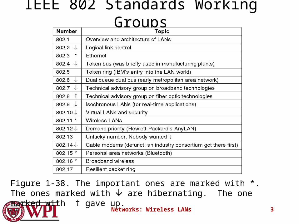
IEEE 802 Standards Working Groups
Figure 1-38. The important ones are marked with *. The ones marked with are hibernating. The one marked with † gave up.
Networks: Wireless LANs 4
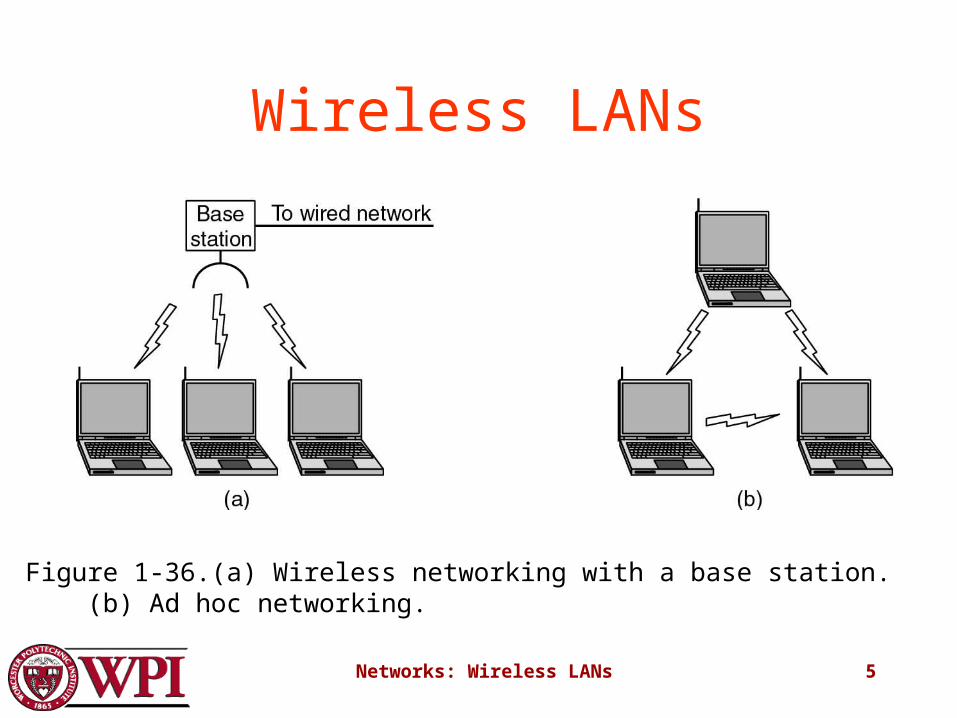
Categories of Wireless Networks• Base Station :: all communication through
an access point {note hub topology}. Other nodes can be fixed or mobile.
• Infrastructure Wireless :: base station network is connected to the wired Internet.
• Ad hoc Wireless :: wireless nodes communicate directly with one another.
• MANETs (Mobile Ad Hoc Networks) :: ad hoc nodes are mobile.
Networks: Wireless LANs 5
Wireless LANs
Figure 1-36.(a) Wireless networking with a base station. (b) Ad hoc networking.
Networks: Wireless LANs 6
The 802.11 Protocol Stack
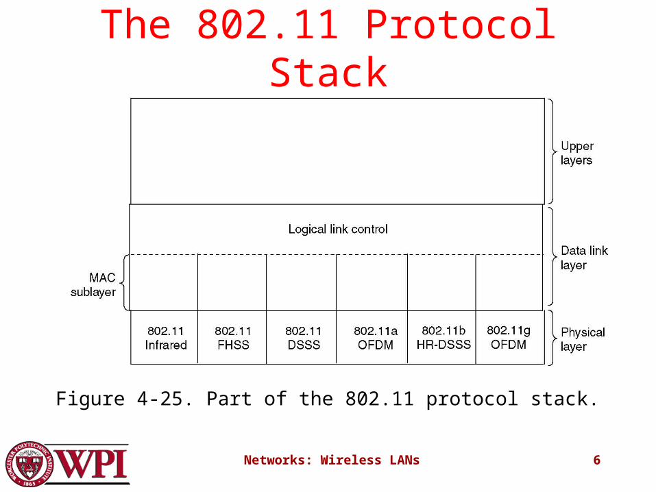
Figure 4-25. Part of the 802.11 protocol stack.
Networks: Wireless LANs 7
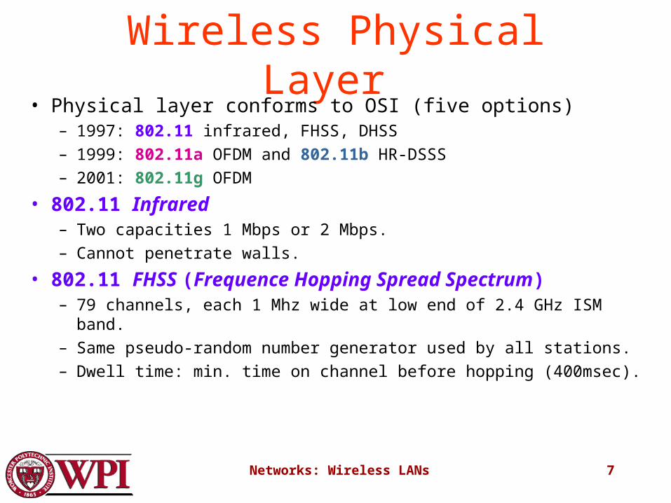
Wireless Physical Layer • Physical layer conforms to OSI (five options)
– 1997: 802.11 infrared, FHSS, DHSS
– 1999: 802.11a OFDM and 802.11b HR-DSSS
– 2001: 802.11g OFDM
• 802.11 Infrared– Two capacities 1 Mbps or 2 Mbps.
– Cannot penetrate walls.
• 802.11 FHSS (Frequence Hopping Spread Spectrum)– 79 channels, each 1 Mhz wide at low end of 2.4 GHz ISM band.
– Same pseudo-random number generator used by all stations.
– Dwell time: min. time on channel before hopping (400msec).
Networks: Wireless LANs 8
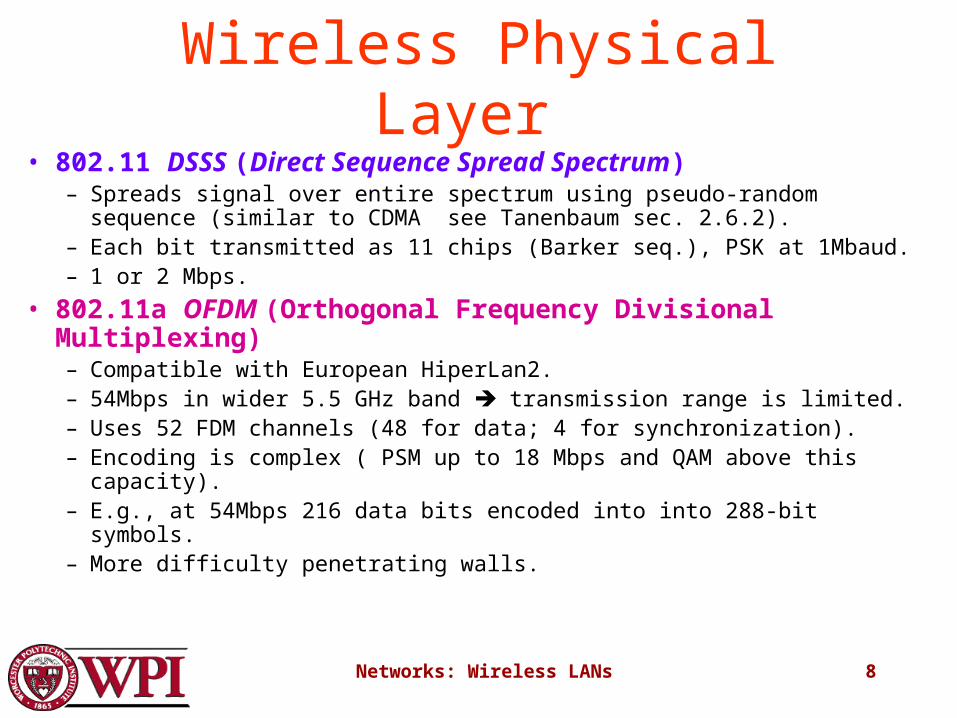
Wireless Physical Layer • 802.11 DSSS (Direct Sequence Spread Spectrum)
– Spreads signal over entire spectrum using pseudo-random sequence (similar to CDMA see Tanenbaum sec. 2.6.2).
– Each bit transmitted as 11 chips (Barker seq.), PSK at 1Mbaud.– 1 or 2 Mbps.
• 802.11a OFDM (Orthogonal Frequency Divisional Multiplexing)– Compatible with European HiperLan2.– 54Mbps in wider 5.5 GHz band transmission range is limited.– Uses 52 FDM channels (48 for data; 4 for synchronization).– Encoding is complex ( PSM up to 18 Mbps and QAM above this capacity).– E.g., at 54Mbps 216 data bits encoded into into 288-bit symbols.– More difficulty penetrating walls.
Networks: Wireless LANs 9
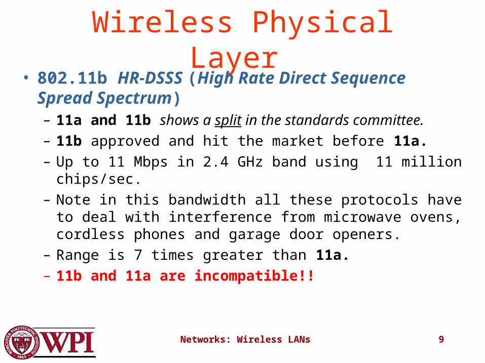
Wireless Physical Layer • 802.11b HR-DSSS (High Rate Direct Sequence
Spread Spectrum)– 11a and 11b shows a split in the standards committee.
– 11b approved and hit the market before 11a.
– Up to 11 Mbps in 2.4 GHz band using 11 million chips/sec.
– Note in this bandwidth all these protocols have to deal with interference from microwave ovens, cordless phones and garage door openers.
– Range is 7 times greater than 11a.
– 11b and 11a are incompatible!!
Networks: Wireless LANs 10
Wireless Physical Layer • 802.11g OFDM(Orthogonal Frequency Division
Multiplexing)– Supports 54 Mbps.
– Uses 2.4 GHz frequency for greater range.
Networks: Wireless LANs 11
802.11 MAC Sublayer Protocol• In 802.11 wireless LANs, “seizing channel” does
not exist as in 802.3 wired Ethernet.• Two additional problems:
– Hidden Terminal Problem– Exposed Station Problem
• To deal with these two problems 802.11 supports two modes of operation DCF (Distributed Coordination Function) and PCF (Point Coordination Function).
• All implementations must support DCF, but PCF is optional.
Networks: Wireless LANs 12
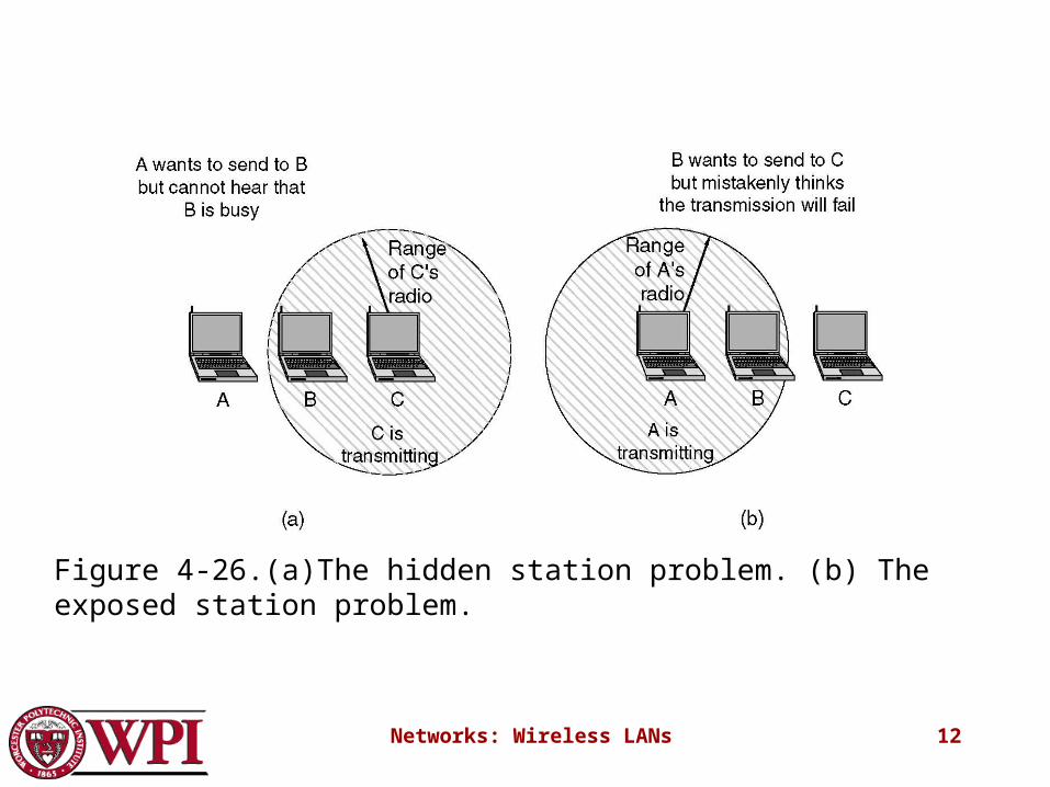
Figure 4-26.(a)The hidden station problem. (b) The exposed station problem.
Networks: Wireless LANs 13
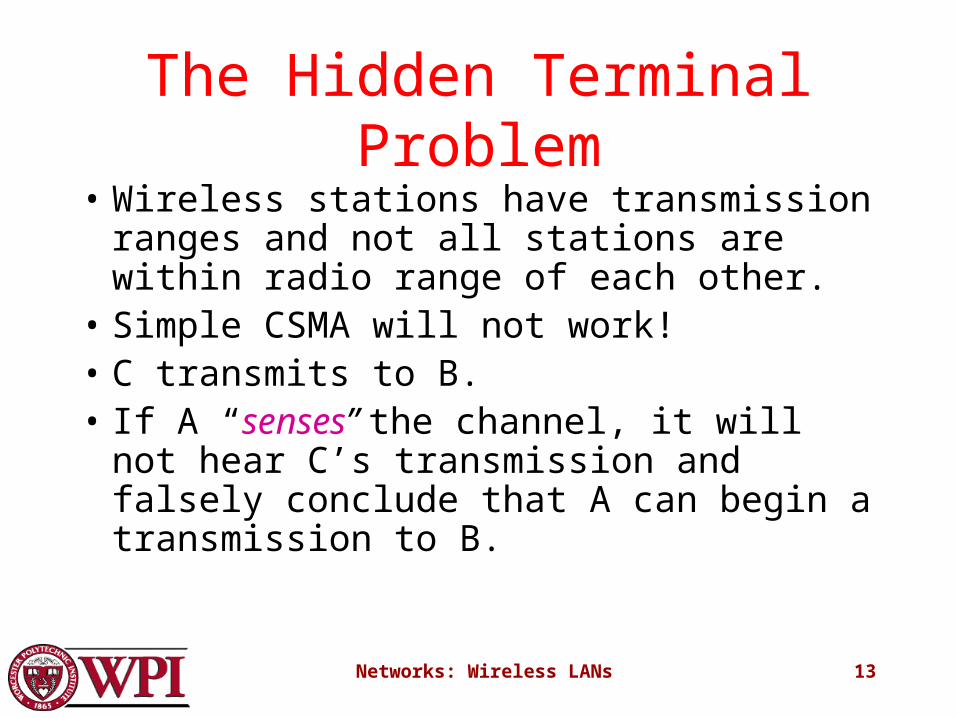
The Hidden Terminal Problem
• Wireless stations have transmission ranges and not all stations are within radio range of each other.
• Simple CSMA will not work!• C transmits to B.• If A “senses” the channel, it will not hear
C’s transmission and falsely conclude that A can begin a transmission to B.
Networks: Wireless LANs 14
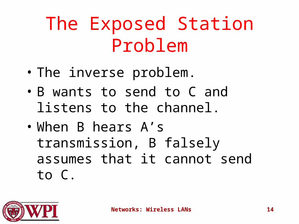
The Exposed Station Problem
• The inverse problem.
• B wants to send to C and listens to the channel.
• When B hears A’s transmission, B falsely assumes that it cannot send to C.

Networks: Wireless LANs 15
Distribute Coordination Function (DCF)
• Uses CSMA/ CA (CSMA with Collision Avoidance).
– Uses both physical and virtual carrier sensing.
– Two methods are supported:
1. based on MACAW with virtual carrier sensing
2. 1-persistent physical carrier sensing.
Networks: Wireless LANs 16
Wireless LAN Protocols
• MACA protocol solved hidden, exposed terminal:– Send Ready-to-Send (RTS) and Clear-to-Send (CTS)
first
– RTS, CTS helps determine who else is in range or busy (Collision avoidance).
– Can a collision still occur?
Professor Agu’s slide
Networks: Wireless LANs 17
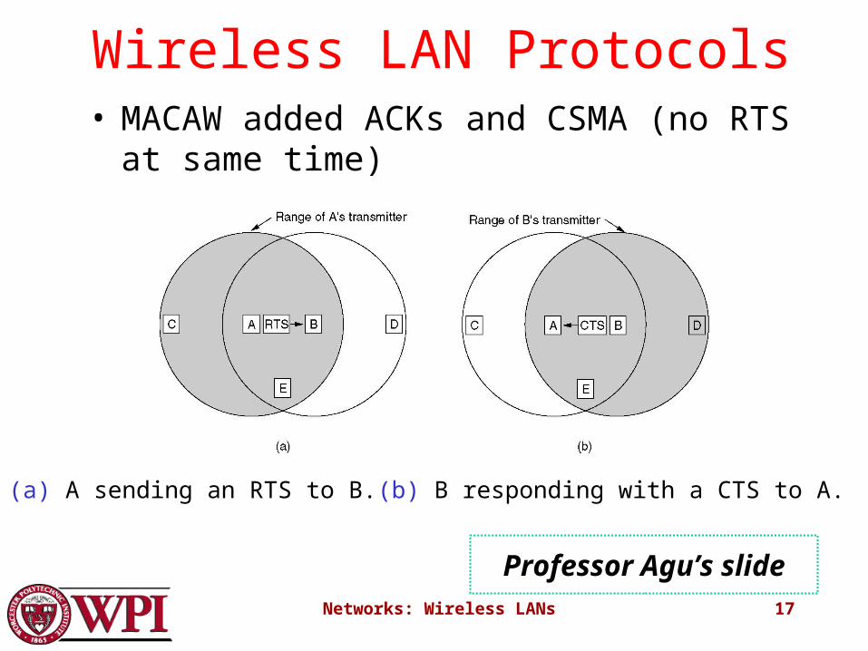
Wireless LAN Protocols
(a) A sending an RTS to B.(b) B responding with a CTS to A.
• MACAW added ACKs and CSMA (no RTS at same time)
Professor Agu’s slide
Networks: Wireless LANs 18
Virtual Channel Sensing in CSMA/CA
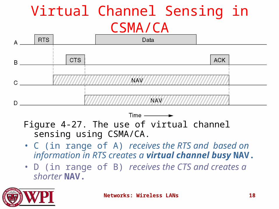
Figure 4-27. The use of virtual channel sensing using CSMA/CA.
• C (in range of A) receives the RTS and based on information in RTS creates a virtual channel busy NAV.
• D (in range of B) receives the CTS and creates a shorter NAV.
Networks: Wireless LANs 19
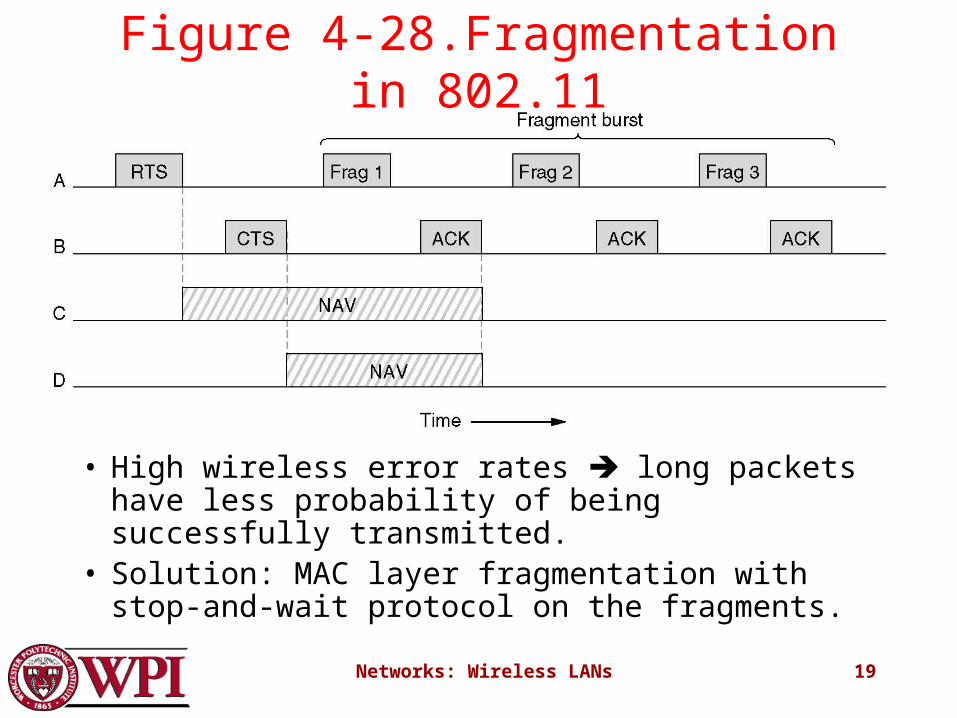
Figure 4-28.Fragmentation in 802.11
• High wireless error rates long packets have less probability of being successfully transmitted.
• Solution: MAC layer fragmentation with stop-and-wait protocol on the fragments.
Networks: Wireless LANs 20
1-Persistent Physical Carrier Sensing
• Station senses the channel when it wants to send.• If idle, station transmits.
– Station does not sense channel while transmitting.
• If the channel is busy, station defers until idle and then transmits.
• Upon collision, wait a random time using binary exponential backoff.

Networks: Wireless LANs 21
Point Coordinated Function (PCF)
• PCF uses a base station to poll other stations to see if they have frames to send.
• No collisions occur.
• Base station sends beacon frame periodically.
• Base station can tell another station to sleep to save on batteries and base stations holds frames for sleeping station.
Networks: Wireless LANs 22
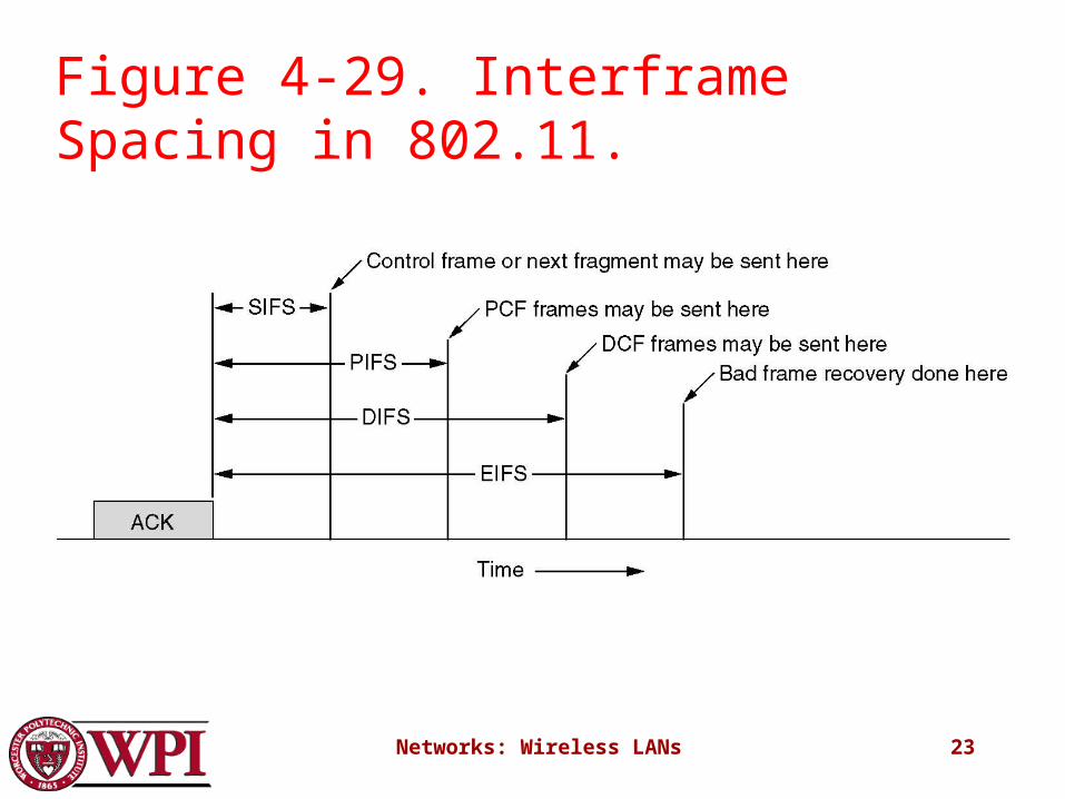
DCF and PCF Co-Existence• Distributed and centralized control can co-exist using
InterFrame Spacing.• SIFS (Short IFS) :: is the time waited between packets
in an ongoing dialog (RTS,CTS,data, ACK, next frame)
• PIFS (PCF IFS) :: when no SIFS response, base station can issue beacon or poll.
• DIFS (DCF IFS) :: when no PIFS, any station can attempt to acquire the channel.
• EIFS (Extended IFS) :: lowest priority interval used to report bad or unknown frame.
Networks: Wireless LANs 23
Figure 4-29. Interframe Spacing in 802.11.