Embed Size (px)
Citation preview
Network Video Recorder (NVR)
User Manual
Issue V4.2
Date 2018-08-15


About This Document
Network Video Recorder
User Manual
Issue: V4.2 (2018-08-15) i
About This Document
Purpose This document describes the network video recorder (NVR) in terms of product
features, hardware installation, network access, network configuration, routine
maintenance, and common fault analysis.
Intended Audience This document is intended for:
Technical support engineers.
Maintenance engineers.
Network video manger system operators.
Symbol Conventions The symbols that can be found in this document are defined as follows:
Symbol Description
Alerts you to a high risk hazard that could, if not avoided,
result in death or serious injury。
Alerts you to a medium or low risk hazard that could, if not
avoided, result in moderate or minor injury.
Alerts you to a potentially hazardous situation which, if not
avoided, result in equipment damage, data loss, performance deterioration, or unanticipated results.
Provides a tip that may help in solving a problem or saving
time.
Provides additional information to emphasize or supplement
important points in the main text.
Important Statement Users are required to enable and maintain the lawful interception (LI) interfaces of
video surveillance products in strict compliance with relevant laws and regulations.
Installation of surveillance devices in an office area by an enterprise or individual to
monitor employee behavior and working efficiency outside the permitted scope of the

ii Issue: V4.2 (2018-08-15)
local law and use of video surveillance devices for eavesdropping of illegal purposes
constitute behaviors of unlawful interception.
Contents
Network Video Recorder
User Manual
Issue: V4.2 (2018-08-15) iii
Contents
About This Document .................................................................................................... i
Contents ........................................................................................................................ iii
1 Preface ........................................................................................................................ 1
1.1 Important Notes .............................................................................................................. 1
1.2 About This User Manual ................................................................................................ 1
1.3 Installation Environment and Precautions ...................................................................... 1
2 Basic Operations ........................................................................................................ 3
2.1 Power on the Device....................................................................................................... 3
2.2 Power off the Device ...................................................................................................... 4
2.3 Log into the System ........................................................................................................ 4
2.4 Add Cameras .................................................................................................................. 5
3 Wizard ........................................................................................................................ 7
4 Quick Navigation ..................................................................................................... 15
4.1 Playback ....................................................................................................................... 16
4.1.1 Time Search ..................................................................................................... 17
4.1.2 Picture Grid ...................................................................................................... 18
4.1.3 Event ................................................................................................................ 19
4.1.4 Backup ............................................................................................................. 20
4.2 Main Menu ................................................................................................................... 21
5 Channel Management ............................................................................................. 23
5.1Camera Management ..................................................................................................... 23
5.1.1 Add a Camera Automatically ........................................................................... 23
5.1.2 Add a Camera Manually ................................................................................... 24
5.1.3 Delete a Camera ............................................................................................... 25
5.2 Encode Parameter ......................................................................................................... 25
5.3 Image Parameter ........................................................................................................... 26
5.4 OSD Settings ................................................................................................................ 27
5.5 Privacy Zone ................................................................................................................ 28
6 Record Management ............................................................................................... 30
6.1 Record Schedule ........................................................................................................... 30
Network Video Recorder
User Manual Contents
iv Issue: V4.2 (2018-08-15)
6.2 Disk .............................................................................................................................. 31
7 Alarm Management ................................................................................................. 33
7.1 General ......................................................................................................................... 33
7.2 Motion Detection.......................................................................................................... 34
7.3 Camera Tamper ............................................................................................................ 35
7.4 Video Loss .................................................................................................................... 36
7.5 Intelligent Analysis ....................................................................................................... 38
7.6 Alarm in ........................................................................................................................ 39
7.7 Device Malfunction ...................................................................................................... 40
8 Network Management ............................................................................................. 41
8.1 Network ........................................................................................................................ 41
8.1.1 IP ...................................................................................................................... 42
8.1.2 Port ................................................................................................................... 42
8.1.3 PoE ................................................................................................................... 43
8.2 DDNS ........................................................................................................................... 43
8.3 E-mail ........................................................................................................................... 44
8.4 UPnP ............................................................................................................................ 45
8.5 P2P ............................................................................................................................... 46
8.6 IP Filter ......................................................................................................................... 47
9 System Setting .......................................................................................................... 50
9.1 Information ................................................................................................................... 50
9.2 General ......................................................................................................................... 51
9.2.1 System .............................................................................................................. 51
9.2.2 Date and Time .................................................................................................. 51
9.2.3 Time Zone ........................................................................................................ 52
9.2.4 DST .................................................................................................................. 53
9.3 User .............................................................................................................................. 54
9.3.1 User .................................................................................................................. 54
9.3.2 Advance Setting ............................................................................................... 57
9.4 Password ...................................................................................................................... 57
9.5 Display ......................................................................................................................... 58
9.6 Logs .............................................................................................................................. 59
9.7 Maintenance ................................................................................................................. 60

Preface
Network Video Recorder
User Manual
Issue: V4.2 (2018-08-15) 1
1 Preface
1.1 Important Notes Thank you for choosing the NVR. Please read the user manual carefully before
using this product.
The NVR is a complex system-based device. To avoid disoperation and malfunctions
caused by environmental factors and human factors during installation, commissioning,
and application, note the following points when installing and using this product:
Read the user manual carefully before installing and using this product.
Use Seagate or Western Digital hard disks as the storage devices of the NVR with
high stability and competitive price/performance ratios (the quality of hard disks
sold on markets varies greatly with different brands and models).
Do not open the outer case of this product unless performed by a professional
person to avoid damage and electric shock.
We are not liable for any video data loss caused by improper installation,
configuration, operation, and hard disk errors.
1.2 About This User Manual Please note the following points before using this user manual:
This user manual is intended for persons who operate and use the NVR.
The information in this user manual applies to the full series NVR, here uses
16ch1HDD NVR as an example for description.
Read this user manual carefully before using the NVR and follow the methods
described in this manual when using the NVR.
If you have any doubts when using the NVR, contact your product seller.
In the case of product upgrade, the information in this document is subject to
change without notice.
1.3 Installation Environment and Precautions
Installation environment
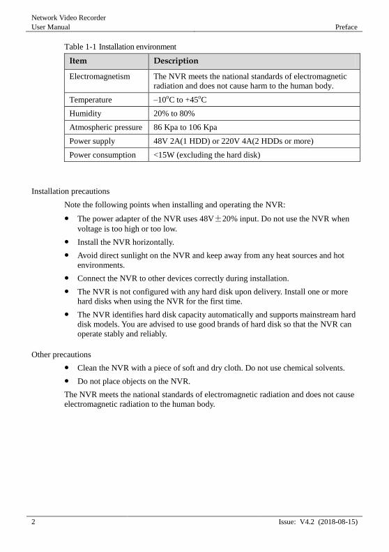
Table 1-1 defines the installation environment of the NVR.
Network Video Recorder
User Manual Preface
2 Issue: V4.2 (2018-08-15)
Table 1-1 Installation environment
Item Description
Electromagnetism The NVR meets the national standards of electromagnetic radiation and does not cause harm to the human body.
Temperature –10oC to +45oC
Humidity 20% to 80%
Atmospheric pressure 86 Kpa to 106 Kpa
Power supply 48V 2A(1 HDD) or 220V 4A(2 HDDs or more)
Power consumption <15W (excluding the hard disk)
Installation precautions
Note the following points when installing and operating the NVR:
The power adapter of the NVR uses 48V±20% input. Do not use the NVR when
voltage is too high or too low.
Install the NVR horizontally.
Avoid direct sunlight on the NVR and keep away from any heat sources and hot
environments.
Connect the NVR to other devices correctly during installation.
The NVR is not configured with any hard disk upon delivery. Install one or more
hard disks when using the NVR for the first time.
The NVR identifies hard disk capacity automatically and supports mainstream hard
disk models. You are advised to use good brands of hard disk so that the NVR can
operate stably and reliably.
Other precautions
Clean the NVR with a piece of soft and dry cloth. Do not use chemical solvents.
Do not place objects on the NVR.
The NVR meets the national standards of electromagnetic radiation and does not cause
electromagnetic radiation to the human body.
Basic Operations
Network Video Recorder
User Manual
Issue: V4.2 (2018-08-15) 3
2 Basic Operations
2.1 Power on the Device
Ensure that the NVR is correctly connected to a power supply, and a display is
correctly connected to the high definition multimedia interface (HD-OUT) or video
graphics array (VGA) port of the NVR before power-on.
In some environments, abnormal power supply may cause the failure of the NVR to
work properly and even damage the NVR in severe cases. It is recommended to use
a regulated power supply to power the NVR in such environments.
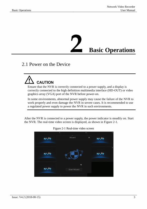
After the NVR is connected to a power supply, the power indicator is steadily on. Start
the NVR. The real-time video screen is displayed, as shown in Figure 2-1.
Figure 2-1 Real-time video screen
Network Video Recorder
User Manual Basic Operations
4 Issue: V4.2 (2018-08-15)
Users need to provide a hard disk for the NVR. The hard disk is strictly detected during
device startup. If the detection result failed, the possible causes are as follows:
The hard disk is new and is not formatted. Log in to the system and format the hard disk.
The hard disk is formatted, but the file system is inconsistent with the file system
supported by the NVR. Format the hard disk.
The hard disk is damaged.
2.2 Power off the Device Click the main menu and choose System > Maintenance, the maintenance page is
displayed. Click Shutdown to power off the NVR. You can choose quick main menu’s
shutdown. If there is a power switch on the real panel of the NVR, you can turn off the
power switch to disconnect the NVR from the power supply.
2.3 Log into the System
Log into the device
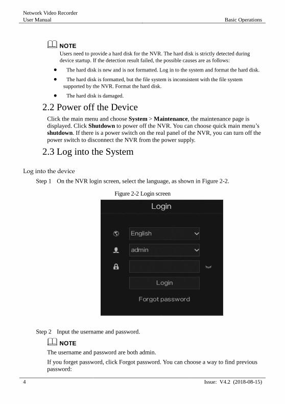
Step 1 On the NVR login screen, select the language, as shown in Figure 2-2.
Figure 2-2 Login screen
Step 2 Input the username and password.
The username and password are both admin.
If you forget password, click Forgot password. You can choose a way to find previous
password:
Basic Operations
Network Video Recorder
User Manual
Issue: V4.2 (2018-08-15) 5
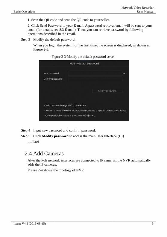
1. Scan the QR code and send the QR code to your seller.
2. Click Send Password to your E-mail. A password retrieval email will be sent to your
email (for details, see 8.3 E-mail). Then, you can retrieve password by following
operations described in the email.
Step 3 Modify the default password.
When you login the system for the first time, the screen is displayed, as shown in
Figure 2-3.
Figure 2-3 Modify the default password screen
Step 4 Input new password and confirm password.
Step 5 Click Modify password to access the main User Interface (UI).
----End
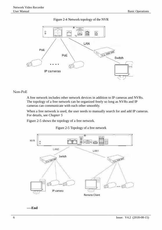
2.4 Add Cameras After the PoE network interfaces are connected to IP cameras, the NVR automatically
adds the IP cameras.
Figure 2-4 shows the topology of NVR
Network Video Recorder
User Manual Basic Operations
6 Issue: V4.2 (2018-08-15)
Figure 2-4 Network topology of the NVR
Non-PoE
A free network includes other network devices in addition to IP cameras and NVRs.
The topology of a free network can be organized freely so long as NVRs and IP
cameras can communicate with each other smoothly.
When a free network is used, the user needs to manually search for and add IP cameras.
For details, see Chapter 5
Figure 2-5 shows the topology of a free network.
Figure 2-5 Topology of a free network
----End

Wizard
Network Video Recorder
User Manual
Issue: V4.2 (2018-08-15) 7
3 Wizard
Start wizard button is on the real-time video screen when you login the NVR, click Start
wizard button, the wizard screen is displayed, as shown in Figure 3-1.
Figure 3-1 Network setting wizard
Operation Steps
Step 1 Set the parameters according to Table 1-2.

Network Video Recorder
User Manual Wizard
8 Issue: V4.2 (2018-08-15)
Table 1-2 NVR network parameters
Parameter Description Setting
Obtain IP address
automatically
The device automatically obtains
the IP address from the DHCP
server.
[Setting method]
Click the button on to enable DHCP.
NOTE
To query the current IP
address of the device, you
must query it on the
platform based on the
device name.
DHCP IP IP address that the DHCP server
assigned to the device.
N/A
IP Address Device IP address that can be set as
required.
[Setting method]
Enter a value manually.
[Default value]
192.168.0.121
Subnet Mask Subnet mask of the network
adapter.
[Setting method]
Enter a value manually.
[Default value]
255.255.255.0
Gateway This parameter must be set if the
client accesses the device through a
gateway.
[Setting method]
Enter a value manually.
[Default value]
192.168.0.1
Obtain DNS
automatically
The device automatically obtains
the DNS address from the DHCP
server.
[Setting method]
Click the button on to
enable Obtain DNS automatically.
NOTE
To query the current DNS
address of the device, you
must query it on the
platform based on the device name.
DNS1 IP address of a DNS server. [Setting method]
Enter a value manually.
[Default value]
192.168.0.1
Wizard
Network Video Recorder
User Manual
Issue: V4.2 (2018-08-15) 9
DNS2 IP address of a domain server.
If the preferred DNS server is
faulty, the device uses the alternate
DNS server to resolve domain
names.
[Setting method]
Enter a value manually.
[Default value]
8.8.8.8
UPnP The method of port mapping. [Setting method]
Select a value from the drop-down list.
[Default value]
Auto
Web Port HTTP port [Setting method]
When UPnP is auto, the ports needn’t set.
When UPnP is manually, Set the ports IP manually.
Data Port -
Client Port -
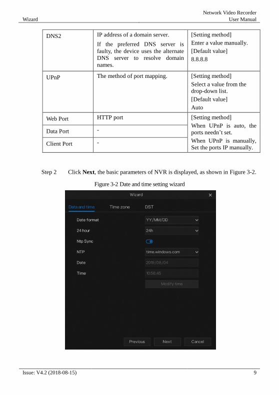
Step 2 Click Next, the basic parameters of NVR is displayed, as shown in Figure 3-2.
Figure 3-2 Date and time setting wizard

Network Video Recorder
User Manual Wizard
10 Issue: V4.2 (2018-08-15)
1. Select a required date format from the Date Format drop-down list.
2. Click drop-down list next to 24 Hour to disable the 24-hour system. Then the 12-
hour system is enabled. If 24 Hour is set on, the 24-hour system is used and is enabled by default.
3. Click next to NTP Sync to disable time synchronization. Time synchronization is enabled by default. Time is synchronized with the PC time.
4. When NTP Sync is disabled, you can set the system time manually.
5. Click Date and scroll the mouse scroll wheel to select the year, month, and date.
6. Click Time and scroll the mouse scroll wheel to select the hour, minute, and
second.
7. Click Modify Time to save the time settings.
Step 3 Go time zone page, select a required time zone from the Time zone drop-down
list, as shown in Figure 3-3.
Figure 3-3 Time zone wizard
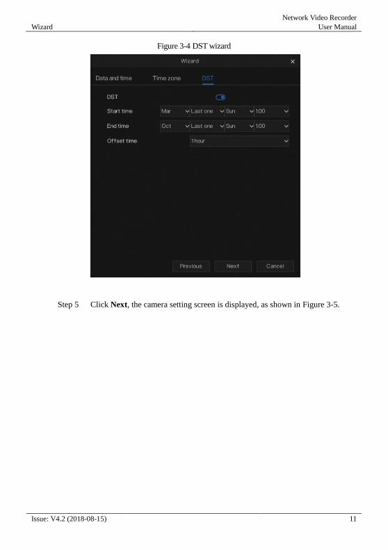
Step 4 Click next to DST to enable DST. And select start time, end time,
offset time from the drop-down list respectively, as shown in Figure 3-4.
Wizard
Network Video Recorder
User Manual
Issue: V4.2 (2018-08-15) 11
Figure 3-4 DST wizard
Step 5 Click Next, the camera setting screen is displayed, as shown in Figure 3-5.
Network Video Recorder
User Manual Wizard
12 Issue: V4.2 (2018-08-15)
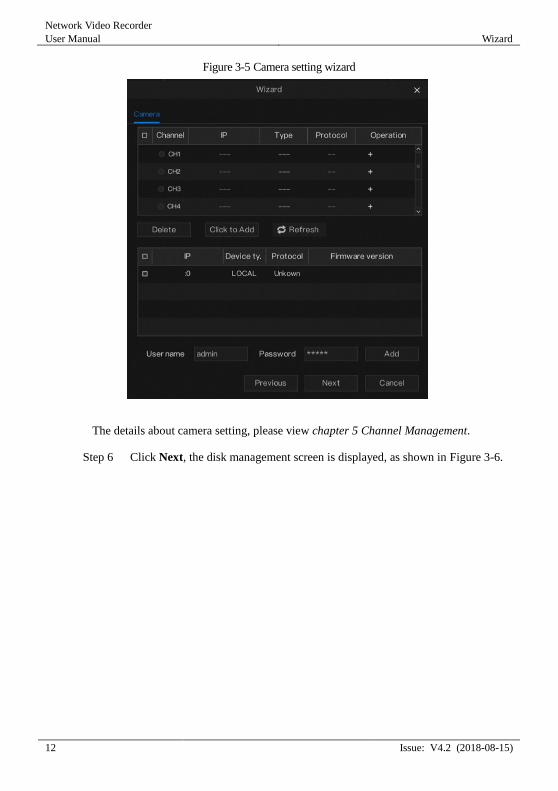
Figure 3-5 Camera setting wizard
The details about camera setting, please view chapter 5 Channel Management.
Step 6 Click Next, the disk management screen is displayed, as shown in Figure 3-6.
Wizard
Network Video Recorder
User Manual
Issue: V4.2 (2018-08-15) 13
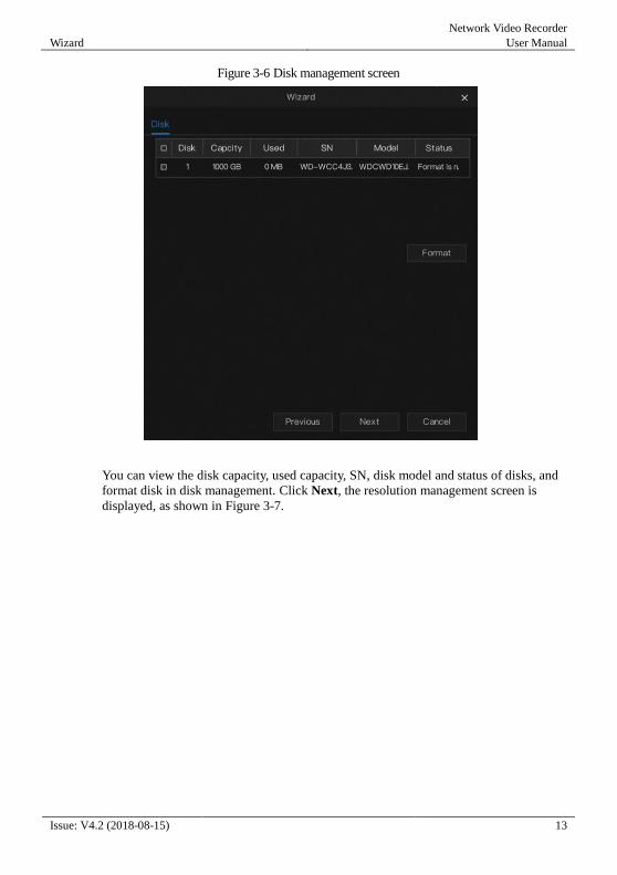
Figure 3-6 Disk management screen
You can view the disk capacity, used capacity, SN, disk model and status of disks, and
format disk in disk management. Click Next, the resolution management screen is
displayed, as shown in Figure 3-7.
Network Video Recorder
User Manual Wizard
14 Issue: V4.2 (2018-08-15)
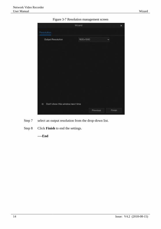
Figure 3-7 Resolution management screen
Step 7 select an output resolution from the drop-down list.
Step 8 Click Finish to end the settings.
----End

Quick Navigation
Network Video Recorder
User Manual
Issue: V4.2 (2018-08-15) 15
4 Quick Navigation
After the NVR operation screen is displayed, move the cursor to the lowest point of the
NVR screen. The NVR floating menu bar is displayed.
Click in the left of NVR floating menu bar, a quick main menu is displayed. The
quick main menu provides Admin, Search, Setup and Shutdown, as shown in Figure
4-1.
Figure 4-1 Quick main menu
In the middle of NVR floating menu bar, the real-time tool bar provides video window
switching, auto SEQ, volume and playback, as shown in Figure 4-2.
Figure 4-2 Real-time video toolbar
The real-time video toolbar is described as follows:
: Layout button. By clicking this button, the real-time video
window is switched between the single-screen mode and multi-screen mode. Click
on the right of screen splitting format and choose the channels to view the video.
Network Video Recorder
User Manual Quick Navigation
16 Issue: V4.2 (2018-08-15)
: Auto SEQ. Click this button to enable/disable SEQ
: Audio button. By clicking this button, the audio setting screen is displayed,
where you can choose the channel and adjust the volume.
An alarm menu quick toolbar is displayed on the right of NVR floating menu bar. The
alarm menu quick toolbar provides Manual Alarm, Alarm information, NVR
information and Time, as shown in Figure 4-3.
Figure 4-3 Alarm menu quick toolbar
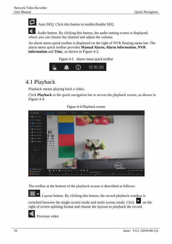
4.1 Playback Playback means playing back a video.
Click Playback in the quick navigation bar to access the playback screen, as shown in
Figure 4-4.
Figure 4-4 Playback screen
The toolbar at the bottom of the playback screen is described as follows:
: Layout button. By clicking this button, the record playback window is
switched between the single-screen mode and multi-screen mode. Click on the
right of screen splitting format and choose the layouts to playback the record.
: Previous video
Quick Navigation
Network Video Recorder
User Manual
Issue: V4.2 (2018-08-15) 17
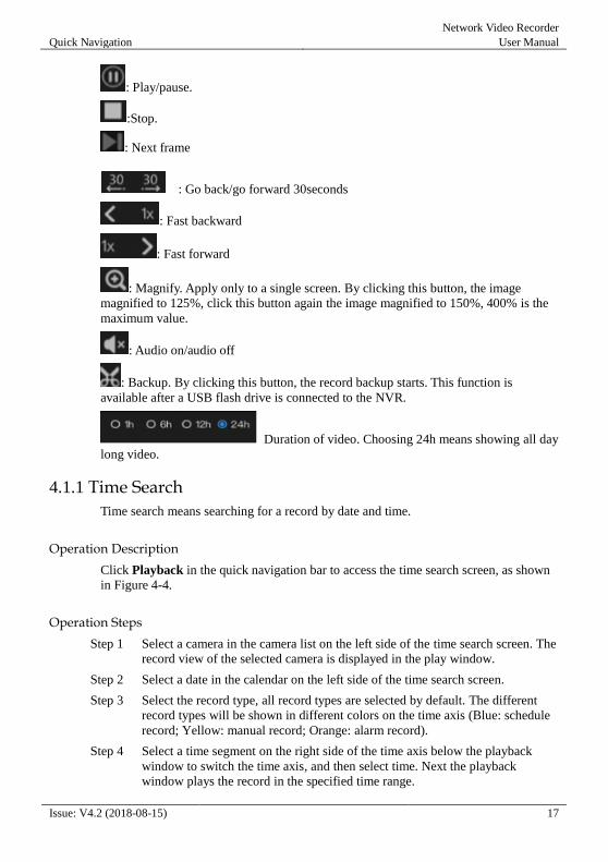
: Play/pause.
:Stop.
: Next frame
: Go back/go forward 30seconds
: Fast backward
: Fast forward
: Magnify. Apply only to a single screen. By clicking this button, the image
magnified to 125%, click this button again the image magnified to 150%, 400% is the
maximum value.
: Audio on/audio off
: Backup. By clicking this button, the record backup starts. This function is
available after a USB flash drive is connected to the NVR.
Duration of video. Choosing 24h means showing all day
long video.
4.1.1 Time Search
Time search means searching for a record by date and time.
Operation Description
Click Playback in the quick navigation bar to access the time search screen, as shown
in Figure 4-4.
Operation Steps
Step 1 Select a camera in the camera list on the left side of the time search screen. The
record view of the selected camera is displayed in the play window.
Step 2 Select a date in the calendar on the left side of the time search screen.
Step 3 Select the record type, all record types are selected by default. The different
record types will be shown in different colors on the time axis (Blue: schedule
record; Yellow: manual record; Orange: alarm record).
Step 4 Select a time segment on the right side of the time axis below the playback
window to switch the time axis, and then select time. Next the playback
window plays the record in the specified time range.
Network Video Recorder
User Manual Quick Navigation
18 Issue: V4.2 (2018-08-15)
----End
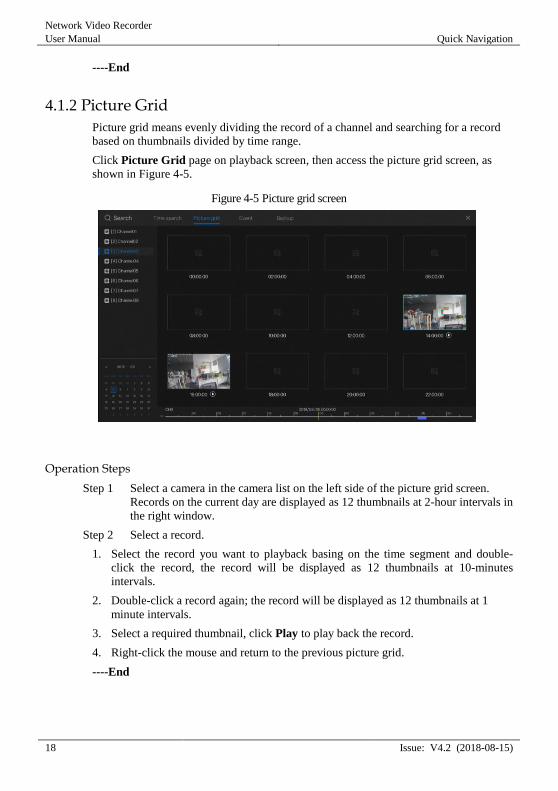
4.1.2 Picture Grid
Picture grid means evenly dividing the record of a channel and searching for a record
based on thumbnails divided by time range.
Click Picture Grid page on playback screen, then access the picture grid screen, as
shown in Figure 4-5.
Figure 4-5 Picture grid screen
Operation Steps
Step 1 Select a camera in the camera list on the left side of the picture grid screen.
Records on the current day are displayed as 12 thumbnails at 2-hour intervals in
the right window.
Step 2 Select a record.
1. Select the record you want to playback basing on the time segment and double-
click the record, the record will be displayed as 12 thumbnails at 10-minutes
intervals.
2. Double-click a record again; the record will be displayed as 12 thumbnails at 1
minute intervals.
3. Select a required thumbnail, click Play to play back the record.
4. Right-click the mouse and return to the previous picture grid.
----End
Quick Navigation
Network Video Recorder
User Manual
Issue: V4.2 (2018-08-15) 19
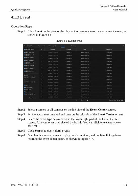
4.1.3 Event
Operation Steps
Step 1 Click Event on the page of the playback screen to access the alarm event screen, as
shown in Figure 4-6.
Figure 4-6 Event screen
Step 2 Select a camera or all cameras on the left side of the Event Center screen.
Step 3 Set the alarm start time and end time on the left side of the Event Center screen.
Step 4 Select the event type below event in the lower right part of the Event Center
screen. All event types are selected by default. You can click one event type to
deselect it.
Step 5 Click Search to query alarm events.
Step 6 Double-click an alarm event to play the alarm video, and double-click again to
return to the event center again, as shown in Figure 4-7.
Network Video Recorder
User Manual Quick Navigation
20 Issue: V4.2 (2018-08-15)
Figure 4-7 Alarm video play screen
----End
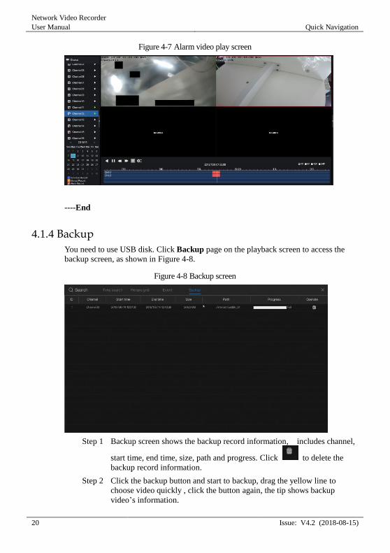
4.1.4 Backup
You need to use USB disk. Click Backup page on the playback screen to access the
backup screen, as shown in Figure 4-8.
Figure 4-8 Backup screen
Step 1 Backup screen shows the backup record information, includes channel,
start time, end time, size, path and progress. Click to delete the
backup record information.
Step 2 Click the backup button and start to backup, drag the yellow line to
choose video quickly , click the button again, the tip shows backup
video’s information.
Quick Navigation
Network Video Recorder
User Manual
Issue: V4.2 (2018-08-15) 21
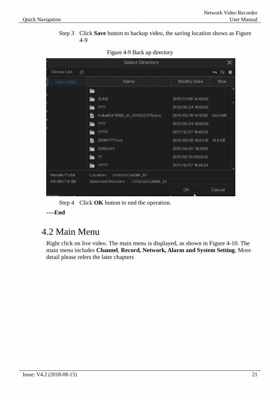
Step 3 Click Save button to backup video, the saving location shows as Figure
4-9
Figure 4-9 Back up directory
Step 4 Click OK button to end the operation.
----End
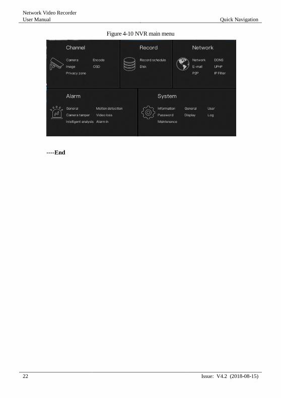
4.2 Main Menu Right click on live video. The main menu is displayed, as shown in Figure 4-10. The
main menu includes Channel, Record, Network, Alarm and System Setting. More
detail please refers the later chapters
Network Video Recorder
User Manual Quick Navigation
22 Issue: V4.2 (2018-08-15)
Figure 4-10 NVR main menu
----End
Channel Management
Network Video Recorder
User Manual
Issue: V4.2 (2018-08-15) 23
5 Channel Management
NVR automatically searches and adds network cameras in the same local area network
(LAN).
Channel management includes adding and deleting cameras, image parameter, encode
parameter, setup OSD and privacy zone.
Operation Description
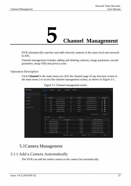
Click Channel in the main menu (or click the channel page of any function screen in
the main menu ) to access the channel management screen, as shown in Figure 5-1.
Figure 5-1 Channel management screen
5.1Camera Management
5.1.1 Add a Camera Automatically
The NVR can add the online camera to the camera list automatically.
Network Video Recorder
User Manual Channel Management
24 Issue: V4.2 (2018-08-15)
On the camera management screen, check the status of channel in the camera list. If the
status of a channel is , this camera has been online. If the status of a channel is ,
this camera has been offline.
Operation Methods
Method 1: Click Refresh button, the cameras show in list, check the need, click Click
to Add, the cameras in the list will be added to the camera list.
Method 2: Select the cameras you wanted to add, and click Add; the selected cameras
will be added to the camera list.
5.1.2 Add a Camera Manually
Operation Steps
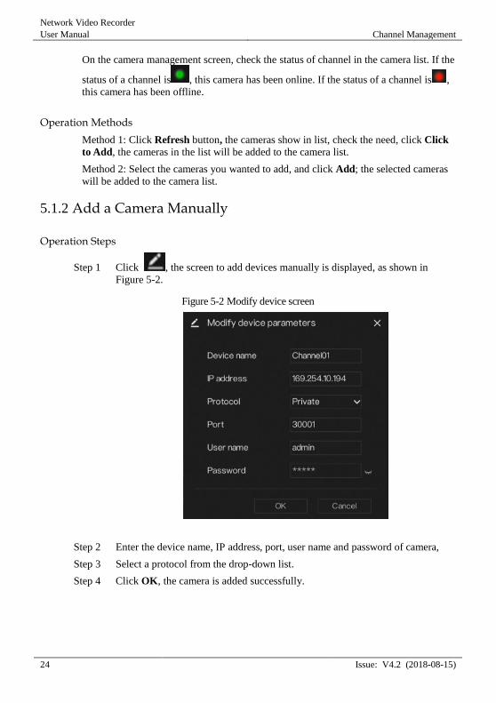
Step 1 Click , the screen to add devices manually is displayed, as shown in
Figure 5-2.
Figure 5-2 Modify device screen
Step 2 Enter the device name, IP address, port, user name and password of camera,
Step 3 Select a protocol from the drop-down list.
Step 4 Click OK, the camera is added successfully.
Channel Management
Network Video Recorder
User Manual
Issue: V4.2 (2018-08-15) 25
If all channels of the NVR are connected by cameras, please delete the cameras that you
don’t need , so that you can add more cameras
If a network camera is added manually, input the correct username and password of the
camera below the online device list. The camera will be added successfully. If not the
camera would be shown on list at offline.
5.1.3 Delete a Camera
Operation Steps
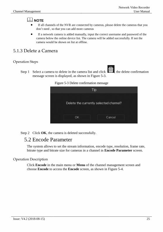
Step 1 Select a camera to delete in the camera list and click , the delete confirmation
message screen is displayed, as shown in Figure 5-3.
Figure 5-3 Delete confirmation message
Step 2 Click OK, the camera is deleted successfully.
5.2 Encode Parameter The system allows to set the stream information, encode type, resolution, frame rate,
bitrate type and bitrate size for cameras in a channel in Encode Parameter screen.
Operation Description
Click Encode in the main menu or Menu of the channel management screen and
choose Encode to access the Encode screen, as shown in Figure 5-4.

Network Video Recorder
User Manual Channel Management
26 Issue: V4.2 (2018-08-15)
Figure 5-4 Encode screen
Operation Steps
Step 1 Select a channel from the drop-down list of channel.
Step 2 Select stream information.
Step 3 Select encode type, resolution, frame rate, bitrate type and bitrate size from the
drop-down lists.
Step 4 Click Copy and select channels, then click OK to apply the parameter settings
to cameras in selected channels , click Apply to save encode parameter settings.
----End
5.3 Image Parameter Image parameters refer to basic attributes of a picture, including the brightness,
sharpness, contrast and saturation. You can set picture parameters for each channel
based on scenarios.
Operation Description
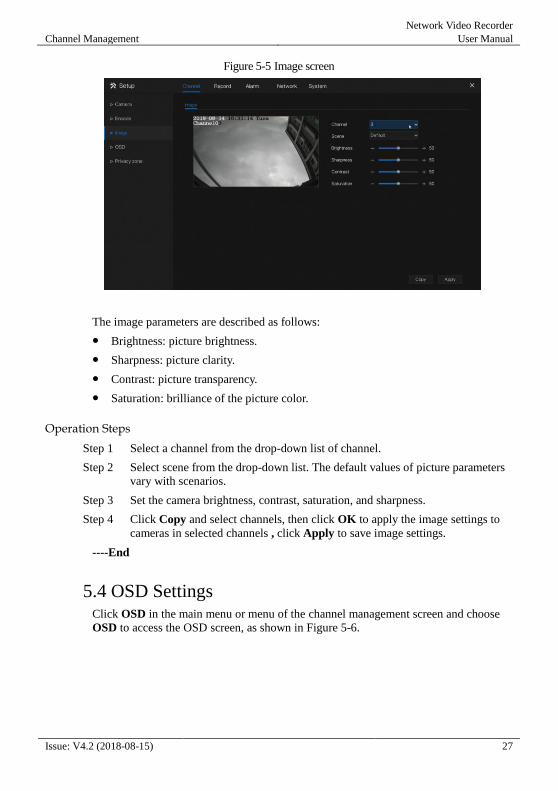
Click Image in the main menu or click menu of the channel management screen and
choose Image to access the image screen, as shown in Figure 5-5.
Channel Management
Network Video Recorder
User Manual
Issue: V4.2 (2018-08-15) 27
Figure 5-5 Image screen
The image parameters are described as follows:
Brightness: picture brightness.
Sharpness: picture clarity.
Contrast: picture transparency.
Saturation: brilliance of the picture color.
Operation Steps
Step 1 Select a channel from the drop-down list of channel.
Step 2 Select scene from the drop-down list. The default values of picture parameters
vary with scenarios.
Step 3 Set the camera brightness, contrast, saturation, and sharpness.
Step 4 Click Copy and select channels, then click OK to apply the image settings to
cameras in selected channels , click Apply to save image settings.
----End
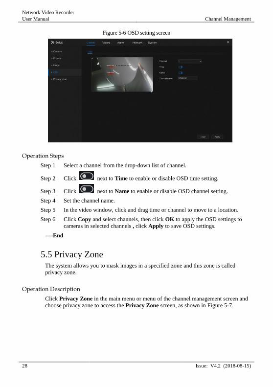
5.4 OSD Settings Click OSD in the main menu or menu of the channel management screen and choose
OSD to access the OSD screen, as shown in Figure 5-6.
Network Video Recorder
User Manual Channel Management
28 Issue: V4.2 (2018-08-15)
Figure 5-6 OSD setting screen
Operation Steps
Step 1 Select a channel from the drop-down list of channel.
Step 2 Click next to Time to enable or disable OSD time setting.
Step 3 Click next to Name to enable or disable OSD channel setting.
Step 4 Set the channel name.
Step 5 In the video window, click and drag time or channel to move to a location.
Step 6 Click Copy and select channels, then click OK to apply the OSD settings to
cameras in selected channels , click Apply to save OSD settings.
----End
5.5 Privacy Zone The system allows you to mask images in a specified zone and this zone is called
privacy zone.
Operation Description
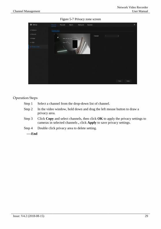
Click Privacy Zone in the main menu or menu of the channel management screen and
choose privacy zone to access the Privacy Zone screen, as shown in Figure 5-7.
Channel Management
Network Video Recorder
User Manual
Issue: V4.2 (2018-08-15) 29
Figure 5-7 Privacy zone screen
Operation Steps
Step 1 Select a channel from the drop-down list of channel.
Step 2 In the video window, hold down and drag the left mouse button to draw a
privacy area.
Step 3 Click Copy and select channels, then click OK to apply the privacy settings to
cameras in selected channels , click Apply to save privacy settings.
Step 4 Double click privacy area to delete setting.
----End
Network Video Recorder
User Manual Record Management
30 Issue: V4.2 (2018-08-15)
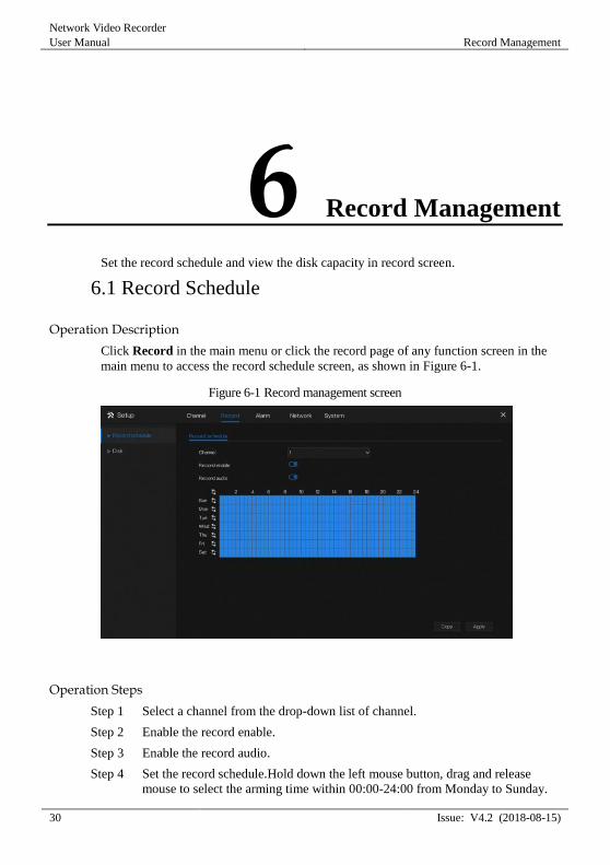
6 Record Management
Set the record schedule and view the disk capacity in record screen.
6.1 Record Schedule
Operation Description
Click Record in the main menu or click the record page of any function screen in the
main menu to access the record schedule screen, as shown in Figure 6-1.
Figure 6-1 Record management screen
Operation Steps
Step 1 Select a channel from the drop-down list of channel.
Step 2 Enable the record enable.
Step 3 Enable the record audio.
Step 4 Set the record schedule.Hold down the left mouse button, drag and release
mouse to select the arming time within 00:00-24:00 from Monday to Sunday.
Record Management
Network Video Recorder
User Manual
Issue: V4.2 (2018-08-15) 31
NOTE
When you select time by dragging the cursor, the cursor cannot be moved out of the time
area. Otherwise, no time can be selected.
Method 2:Click in the record schedule page to select the whole day or whole
week.
Step 5 Deleting record schedule: Click again or inverse selection to delete the
selected record schedule.
Step 6 Click Copy and select channels, then click OK to apply the record
management settings to cameras in selected channels , click Apply to save
settings.
----End
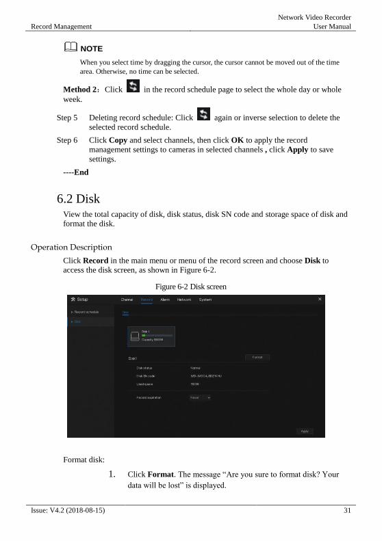
6.2 Disk View the total capacity of disk, disk status, disk SN code and storage space of disk and
format the disk.
Operation Description
Click Record in the main menu or menu of the record screen and choose Disk to
access the disk screen, as shown in Figure 6-2.
Figure 6-2 Disk screen
Format disk:
1. Click Format. The message “Are you sure to format disk? Your
data will be lost” is displayed.
Network Video Recorder
User Manual Record Management
32 Issue: V4.2 (2018-08-15)
2. Click OK, and the disk is formatted.
Record expiration setting:
Step 1 Select record expiration days from the drop-down list of record expiration.
Step 2 Click Apply to save the settings.
----End
Alarm Management
Network Video Recorder
User Manual
Issue: V4.2 (2018-08-15) 33
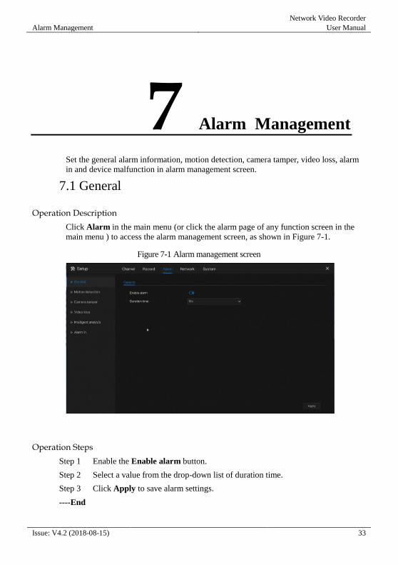
7 Alarm Management
Set the general alarm information, motion detection, camera tamper, video loss, alarm
in and device malfunction in alarm management screen.
7.1 General
Operation Description
Click Alarm in the main menu (or click the alarm page of any function screen in the
main menu ) to access the alarm management screen, as shown in Figure 7-1.
Figure 7-1 Alarm management screen
Operation Steps
Step 1 Enable the Enable alarm button.
Step 2 Select a value from the drop-down list of duration time.
Step 3 Click Apply to save alarm settings.
----End
Network Video Recorder
User Manual Alarm Management
34 Issue: V4.2 (2018-08-15)
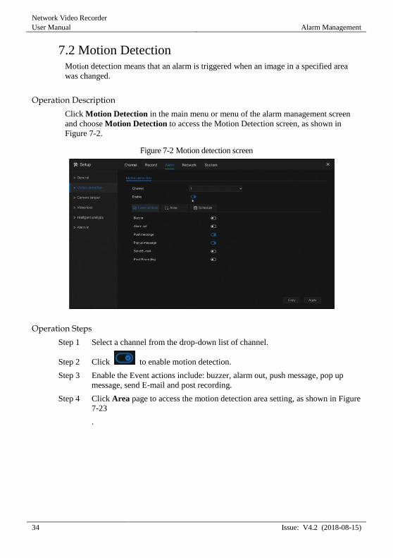
7.2 Motion Detection Motion detection means that an alarm is triggered when an image in a specified area
was changed.
Operation Description
Click Motion Detection in the main menu or menu of the alarm management screen
and choose Motion Detection to access the Motion Detection screen, as shown in
Figure 7-2.
Figure 7-2 Motion detection screen
Operation Steps
Step 1 Select a channel from the drop-down list of channel.
Step 2 Click to enable motion detection.
Step 3 Enable the Event actions include: buzzer, alarm out, push message, pop up
message, send E-mail and post recording.
Step 4 Click Area page to access the motion detection area setting, as shown in Figure
7-23
.
Alarm Management
Network Video Recorder
User Manual
Issue: V4.2 (2018-08-15) 35
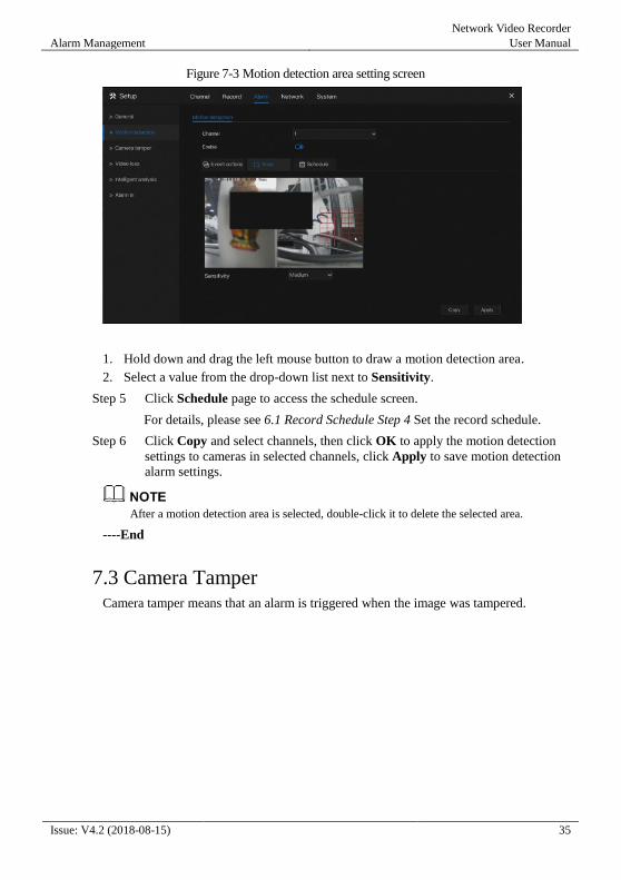
Figure 7-3 Motion detection area setting screen
1. Hold down and drag the left mouse button to draw a motion detection area.
2. Select a value from the drop-down list next to Sensitivity.
Step 5 Click Schedule page to access the schedule screen.
For details, please see 6.1 Record Schedule Step 4 Set the record schedule.
Step 6 Click Copy and select channels, then click OK to apply the motion detection
settings to cameras in selected channels, click Apply to save motion detection
alarm settings.
After a motion detection area is selected, double-click it to delete the selected area.
----End
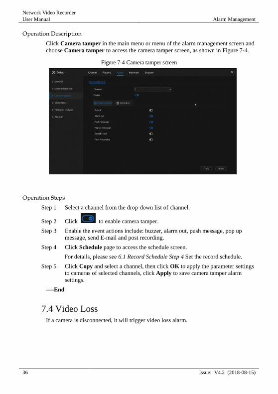
7.3 Camera Tamper Camera tamper means that an alarm is triggered when the image was tampered.
Network Video Recorder
User Manual Alarm Management
36 Issue: V4.2 (2018-08-15)
Operation Description
Click Camera tamper in the main menu or menu of the alarm management screen and
choose Camera tamper to access the camera tamper screen, as shown in Figure 7-4.
Figure 7-4 Camera tamper screen
Operation Steps
Step 1 Select a channel from the drop-down list of channel.
Step 2 Click to enable camera tamper.
Step 3 Enable the event actions include: buzzer, alarm out, push message, pop up
message, send E-mail and post recording.
Step 4 Click Schedule page to access the schedule screen.
For details, please see 6.1 Record Schedule Step 4 Set the record schedule.
Step 5 Click Copy and select a channel, then click OK to apply the parameter settings
to cameras of selected channels, click Apply to save camera tamper alarm
settings.
----End
7.4 Video Loss If a camera is disconnected, it will trigger video loss alarm.
Alarm Management
Network Video Recorder
User Manual
Issue: V4.2 (2018-08-15) 37
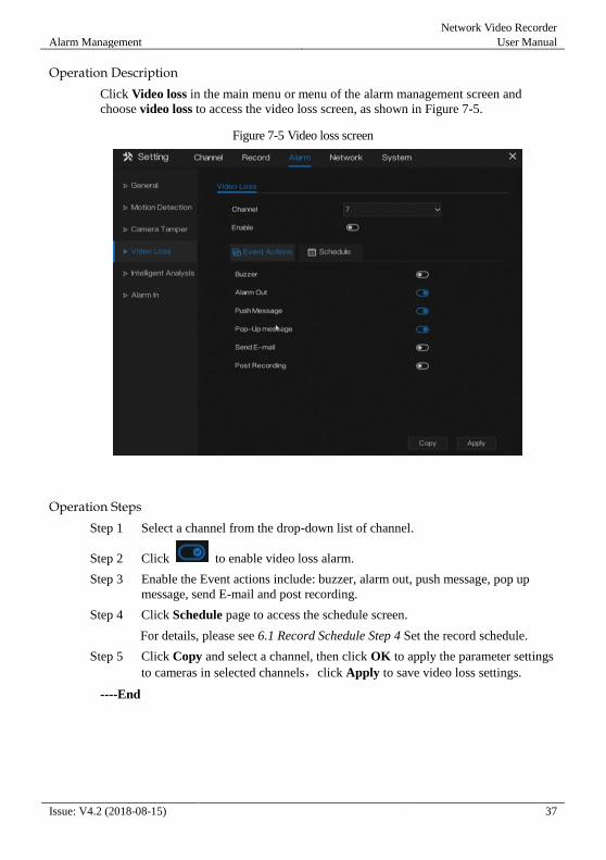
Operation Description
Click Video loss in the main menu or menu of the alarm management screen and
choose video loss to access the video loss screen, as shown in Figure 7-5.
Figure 7-5 Video loss screen
Operation Steps
Step 1 Select a channel from the drop-down list of channel.
Step 2 Click to enable video loss alarm.
Step 3 Enable the Event actions include: buzzer, alarm out, push message, pop up
message, send E-mail and post recording.
Step 4 Click Schedule page to access the schedule screen.
For details, please see 6.1 Record Schedule Step 4 Set the record schedule.
Step 5 Click Copy and select a channel, then click OK to apply the parameter settings
to cameras in selected channels,click Apply to save video loss settings.
----End
Network Video Recorder
User Manual Alarm Management
38 Issue: V4.2 (2018-08-15)
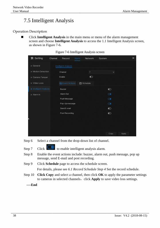
7.5 Intelligent Analysis
Operation Description
Click Intelligent Analysis in the main menu or menu of the alarm management
screen and choose Intelligent Analysis to access the 1.1 Intelligent Analysis screen,
as shown in Figure 7-6.
Figure 7-6 Intelligent Analysis screen
Step 6 Select a channel from the drop-down list of channel.
Step 7 Click to enable intelligent analysis alarm.
Step 8 Enable the event actions include: buzzer, alarm out, push message, pop up
message, send E-mail and post recording.
Step 9 Click Schedule page to access the schedule screen.
For details, please see 6.1 Record Schedule Step 4 Set the record schedule.
Step 10 Click Copy and select a channel, then click OK to apply the parameter settings
to cameras in selected channels,click Apply to save video loss settings.
----End
Alarm Management
Network Video Recorder
User Manual
Issue: V4.2 (2018-08-15) 39
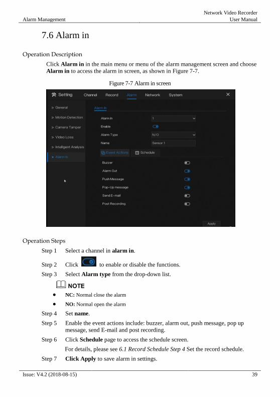
7.6 Alarm in
Operation Description
Click Alarm in in the main menu or menu of the alarm management screen and choose
Alarm in to access the alarm in screen, as shown in Figure 7-7.
Figure 7-7 Alarm in screen
Operation Steps
Step 1 Select a channel in alarm in.
Step 2 Click to enable or disable the functions.
Step 3 Select Alarm type from the drop-down list.
NC: Normal close the alarm
NO: Normal open the alarm
Step 4 Set name.
Step 5 Enable the event actions include: buzzer, alarm out, push message, pop up
message, send E-mail and post recording.
Step 6 Click Schedule page to access the schedule screen.
For details, please see 6.1 Record Schedule Step 4 Set the record schedule.
Step 7 Click Apply to save alarm in settings.
Network Video Recorder
User Manual Alarm Management
40 Issue: V4.2 (2018-08-15)
----End
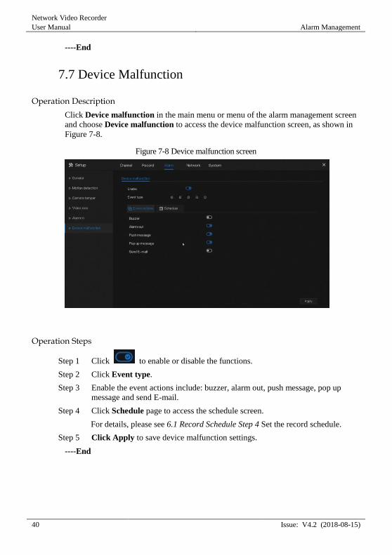
7.7 Device Malfunction
Operation Description
Click Device malfunction in the main menu or menu of the alarm management screen
and choose Device malfunction to access the device malfunction screen, as shown in
Figure 7-8.
Figure 7-8 Device malfunction screen
Operation Steps
Step 1 Click to enable or disable the functions.
Step 2 Click Event type.
Step 3 Enable the event actions include: buzzer, alarm out, push message, pop up
message and send E-mail.
Step 4 Click Schedule page to access the schedule screen.
For details, please see 6.1 Record Schedule Step 4 Set the record schedule.
Step 5 Click Apply to save device malfunction settings.
----End
Network Management
Network Video Recorder
User Manual
Issue: V4.2 (2018-08-15) 41
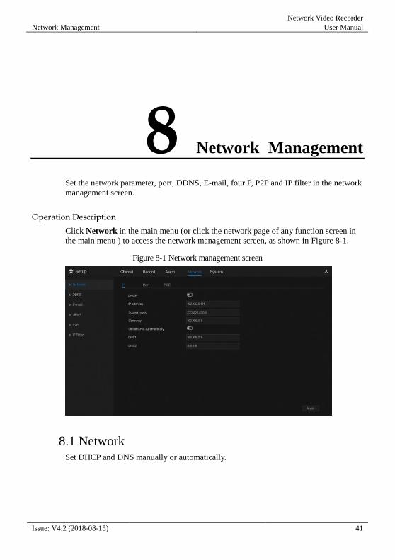
8 Network Management
Set the network parameter, port, DDNS, E-mail, four P, P2P and IP filter in the network
management screen.
Operation Description
Click Network in the main menu (or click the network page of any function screen in
the main menu ) to access the network management screen, as shown in Figure 8-1.
Figure 8-1 Network management screen
8.1 Network Set DHCP and DNS manually or automatically.
Network Video Recorder
User Manual Network Management
42 Issue: V4.2 (2018-08-15)
8.1.1 IP
Operation Steps
Step 1 Click next to DHCP to enable or disable the function of automatically
getting an IP address. The function is disabled by default.
If the function is disabled, click input boxes next to IP, Subnet mask, and
Gateway to set the parameters as required.
Step 2 Click next to Obtain DNS Automatically to enable or disable the function
of automatically getting a DNS address. The function is enabled by default.
If the function is disabled, click input boxes next to DNS1(default 192.168.0.1)
and DNS2(default 8.8.8.8), delete original address, and enter new address.
Step 3 Click Apply to save IP settings.
----End
8.1.2 Port
Operation Steps
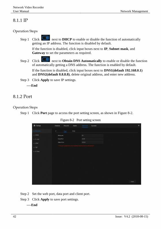
Step 1 Click Port page to access the port setting screen, as shown in Figure 8-2.
Figure 8-2 Port setting screen
Step 2 Set the web port, data port and client port.
Step 3 Click Apply to save port settings.
----End
Network Management
Network Video Recorder
User Manual
Issue: V4.2 (2018-08-15) 43
8.1.3 PoE
Operation Steps
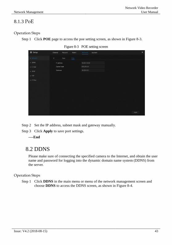
Step 1 Click POE page to access the poe setting screen, as shown in Figure 8-3.
Figure 8-3 POE setting screen
Step 2 Set the IP address, subnet mask and gateway manually.
Step 3 Click Apply to save port settings.
----End
8.2 DDNS Please make sure of connecting the specified camera to the Internet, and obtain the user
name and password for logging into the dynamic domain name system (DDNS) from
the server.
Operation Steps
Step 1 Click DDNS in the main menu or menu of the network management screen and
choose DDNS to access the DDNS screen, as shown in Figure 8-4.

Network Video Recorder
User Manual Network Management
44 Issue: V4.2 (2018-08-15)
Figure 8-4 DDNS setting screen
Step 2 Click next to Enable to enable the DDNS function. It is disabled by default.
Step 3 Select a required value from the protocol drop-down list.
Step 4 Set domain name.
Step 5 Set the DDNS account and password.
Step 6 Click Apply to save DDNS network settings
An external network can access the NVR via an address which is specified in the DDNS
settings.
----End
8.3 E-mail If the simple mail transfer protocol (SMTP) function is enabled, the device
automatically sends alarm information to specified email addresses when an alarm is
generated.
Operation Steps
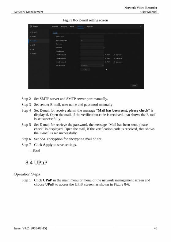
Step 1 Click E-mail in the main menu or menu of the network management screen and
choose E-mail to access the E-mail screen, as shown in Figure 8-5.
Network Management
Network Video Recorder
User Manual
Issue: V4.2 (2018-08-15) 45
Figure 8-5 E-mail setting screen
Step 2 Set SMTP server and SMTP server port manually.
Step 3 Set sender E-mail, user name and password manually.
Step 4 Set E-mail for receive alarm. the message “Mail has been sent, please check” is
displayed. Open the mail, if the verification code is received, that shows the E-mail
is set successfully.
Step 5 Set E-mail for retrieve the password. the message “Mail has been sent, please
check” is displayed. Open the mail, if the verification code is received, that shows
the E-mail is set successfully.
Step 6 Set SSL encryption for encrypting mail or not.
Step 7 Click Apply to save settings.
----End
8.4 UPnP
Operation Steps
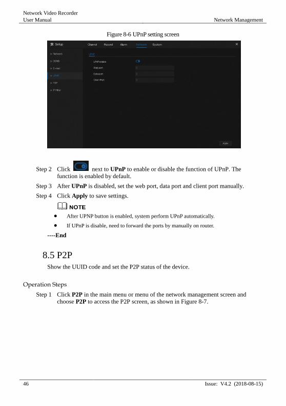
Step 1 Click UPnP in the main menu or menu of the network management screen and
choose UPnP to access the UPnP screen, as shown in Figure 8-6.
Network Video Recorder
User Manual Network Management
46 Issue: V4.2 (2018-08-15)
Figure 8-6 UPnP setting screen
Step 2 Click next to UPnP to enable or disable the function of UPnP. The
function is enabled by default.
Step 3 After UPnP is disabled, set the web port, data port and client port manually.
Step 4 Click Apply to save settings.
After UPNP button is enabled, system perform UPnP automatically.
If UPnP is disable, need to forward the ports by manually on router.
----End
8.5 P2P Show the UUID code and set the P2P status of the device.
Operation Steps
Step 1 Click P2P in the main menu or menu of the network management screen and
choose P2P to access the P2P screen, as shown in Figure 8-7.

Network Management
Network Video Recorder
User Manual
Issue: V4.2 (2018-08-15) 47
Figure 8-7 P2P screen
Step 2 Click the Enable button to enable the P2P function.
Step 3 Click Apply to save P2P network settings or click Cancel to cancel settings.
Step 4 After the Inview Pro4 is installed in mobile phone, run the APP and scan the
UUID QR code to add and access the NVR when the device is online.
----End
8.6 IP Filter Set the IP address in specified network segment to allow access or prohibit access.
Operation Steps
Step 1 Click IP Filter in the main menu or menu of the network management screen and
choose IP Filter to access the IP filter screen, as shown in Figure 8-8.
Network Video Recorder
User Manual Network Management
48 Issue: V4.2 (2018-08-15)
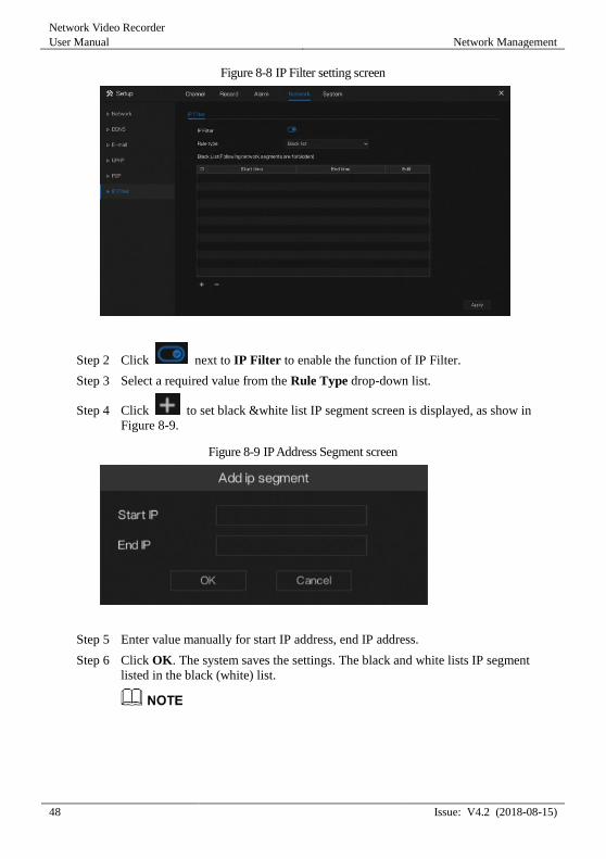
Figure 8-8 IP Filter setting screen
Step 2 Click next to IP Filter to enable the function of IP Filter.
Step 3 Select a required value from the Rule Type drop-down list.
Step 4 Click to set black &white list IP segment screen is displayed, as show in
Figure 8-9.
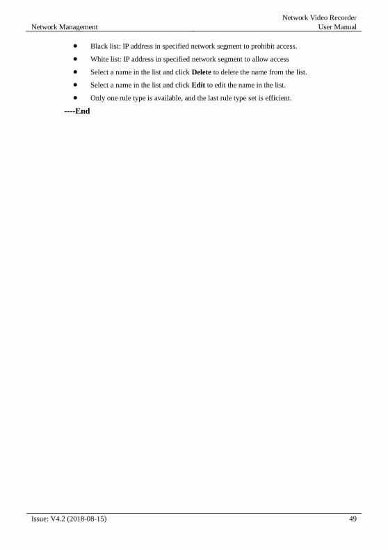
Figure 8-9 IP Address Segment screen
Step 5 Enter value manually for start IP address, end IP address.
Step 6 Click OK. The system saves the settings. The black and white lists IP segment
listed in the black (white) list.
Network Management
Network Video Recorder
User Manual
Issue: V4.2 (2018-08-15) 49
Black list: IP address in specified network segment to prohibit access.
White list: IP address in specified network segment to allow access
Select a name in the list and click Delete to delete the name from the list.
Select a name in the list and click Edit to edit the name in the list.
Only one rule type is available, and the last rule type set is efficient.
----End
Network Video Recorder
User Manual 9 System Setting
50 Issue: V4.2 (2018-08-15)
9 System Setting
View the device information and set general information, user, password, display, logs
and maintenance for the system setting.
Operation Description
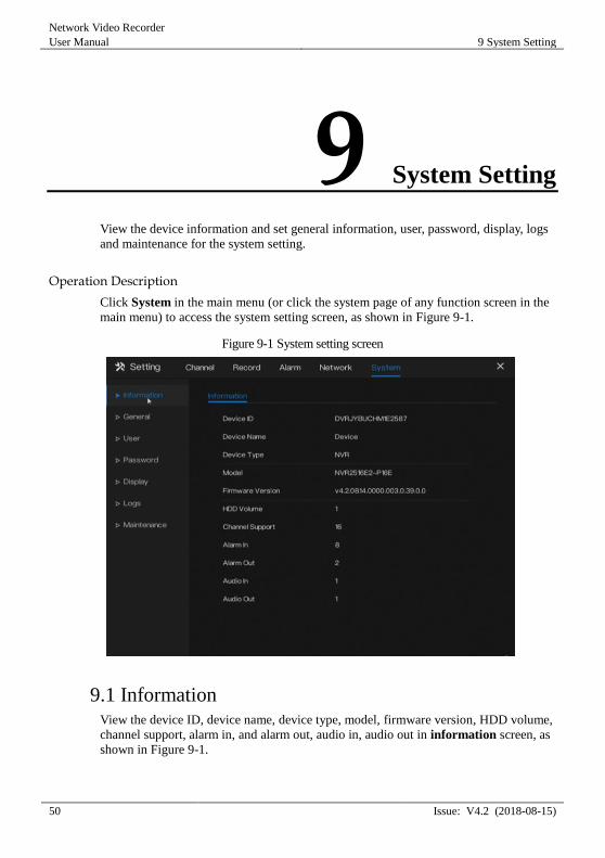
Click System in the main menu (or click the system page of any function screen in the
main menu) to access the system setting screen, as shown in Figure 9-1.
Figure 9-1 System setting screen
9.1 Information View the device ID, device name, device type, model, firmware version, HDD volume,
channel support, alarm in, and alarm out, audio in, audio out in information screen, as
shown in Figure 9-1.
System Setting
Network Video Recorder
User Manual
Issue: V4.2 (2018-08-15) 51
9.2 General
9.2.1 System
Operation Steps
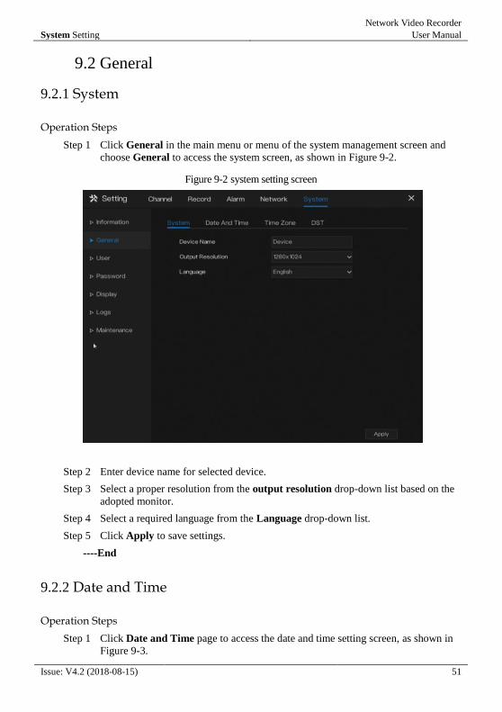
Step 1 Click General in the main menu or menu of the system management screen and
choose General to access the system screen, as shown in Figure 9-2.
Figure 9-2 system setting screen
Step 2 Enter device name for selected device.
Step 3 Select a proper resolution from the output resolution drop-down list based on the
adopted monitor.
Step 4 Select a required language from the Language drop-down list.
Step 5 Click Apply to save settings.
----End
9.2.2 Date and Time
Operation Steps
Step 1 Click Date and Time page to access the date and time setting screen, as shown in
Figure 9-3.
Network Video Recorder
User Manual 9 System Setting
52 Issue: V4.2 (2018-08-15)
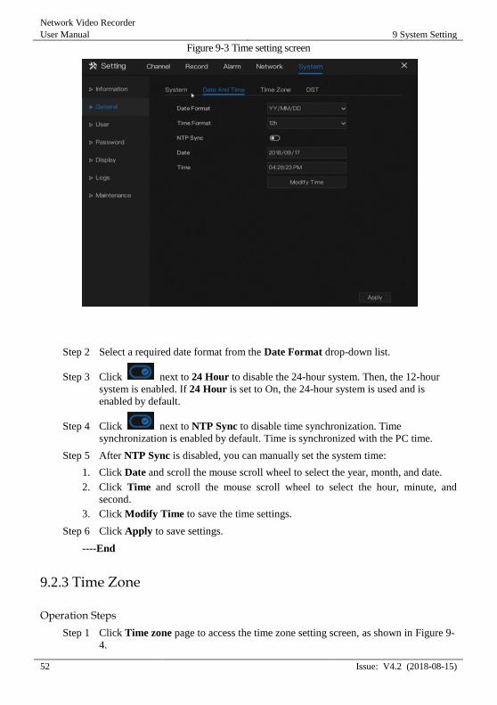
Figure 9-3 Time setting screen
Step 2 Select a required date format from the Date Format drop-down list.
Step 3 Click next to 24 Hour to disable the 24-hour system. Then, the 12-hour
system is enabled. If 24 Hour is set to On, the 24-hour system is used and is
enabled by default.
Step 4 Click next to NTP Sync to disable time synchronization. Time
synchronization is enabled by default. Time is synchronized with the PC time.
Step 5 After NTP Sync is disabled, you can manually set the system time:
1. Click Date and scroll the mouse scroll wheel to select the year, month, and date.
2. Click Time and scroll the mouse scroll wheel to select the hour, minute, and
second.
3. Click Modify Time to save the time settings.
Step 6 Click Apply to save settings.
----End
9.2.3 Time Zone
Operation Steps
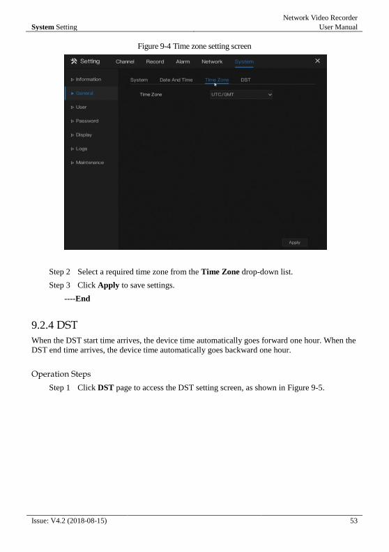
Step 1 Click Time zone page to access the time zone setting screen, as shown in Figure 9-
4.
System Setting
Network Video Recorder
User Manual
Issue: V4.2 (2018-08-15) 53
Figure 9-4 Time zone setting screen
Step 2 Select a required time zone from the Time Zone drop-down list.
Step 3 Click Apply to save settings.
----End
9.2.4 DST
When the DST start time arrives, the device time automatically goes forward one hour. When the
DST end time arrives, the device time automatically goes backward one hour.
Operation Steps
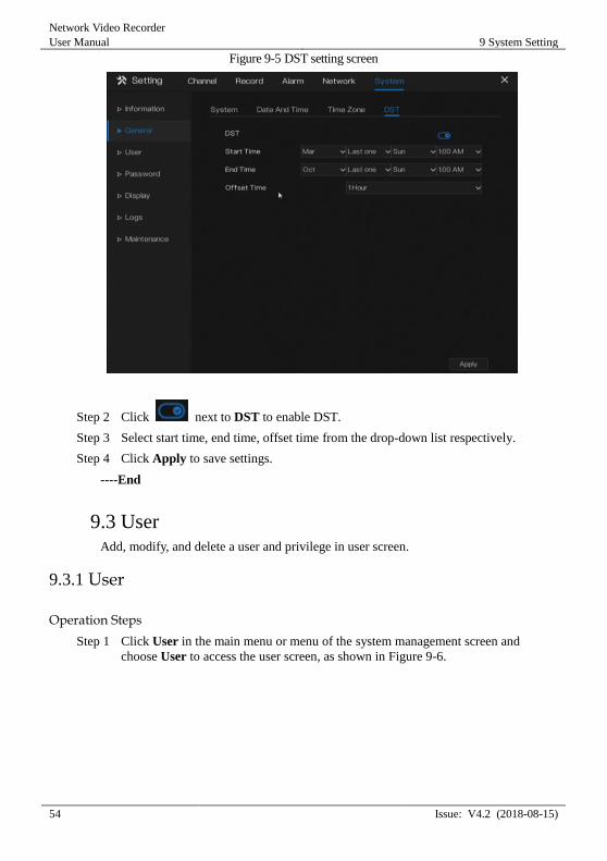
Step 1 Click DST page to access the DST setting screen, as shown in Figure 9-5.
Network Video Recorder
User Manual 9 System Setting
54 Issue: V4.2 (2018-08-15)
Figure 9-5 DST setting screen
Step 2 Click next to DST to enable DST.
Step 3 Select start time, end time, offset time from the drop-down list respectively.
Step 4 Click Apply to save settings.
----End
9.3 User Add, modify, and delete a user and privilege in user screen.
9.3.1 User
Operation Steps
Step 1 Click User in the main menu or menu of the system management screen and
choose User to access the user screen, as shown in Figure 9-6.
System Setting
Network Video Recorder
User Manual
Issue: V4.2 (2018-08-15) 55
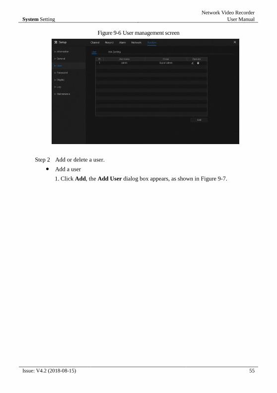
Figure 9-6 User management screen
Step 2 Add or delete a user.
Add a user
1. Click Add, the Add User dialog box appears, as shown in Figure 9-7.
Network Video Recorder
User Manual 9 System Setting
56 Issue: V4.2 (2018-08-15)
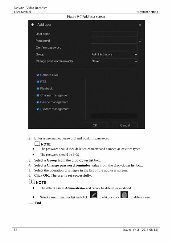
Figure 9-7 Add user screen
2. Enter a username, password and confirm password.
The password should include letter, character and number, at least two types.
The password should be 6~32.
3. Select a Group from the drop-down list box.
4. Select a Change password reminder value from the drop-down list box.
5. Select the operation privileges in the list of the add user screen.
6. Click OK. The user is set successfully.
The default user is Administrator and cannot be deleted or modified.
Select a user from user list and click to edit , or click to delete a user.
-----End
System Setting
Network Video Recorder
User Manual
Issue: V4.2 (2018-08-15) 57
9.3.2 Advance Setting
Operation Steps
Step 1 Click User in the main menu or menu of the system management screen and
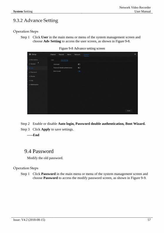
choose Adv Setting to access the user screen, as shown in Figure 9-8.
Figure 9-8 Advance setting screen
Step 2 Enable or disable Auto login, Password double authentication, Boot Wizard.
Step 3 Click Apply to save settings.
-----End
9.4 Password Modify the old password.
Operation Steps
Step 1 Click Password in the main menu or menu of the system management screen and
choose Password to access the modify password screen, as shown in Figure 9-9.
Network Video Recorder
User Manual 9 System Setting
58 Issue: V4.2 (2018-08-15)
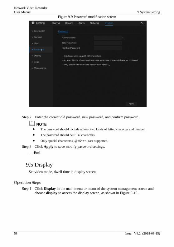
Figure 9-9 Password modification screen
Step 2 Enter the correct old password, new password, and confirm password.
The password should include at least two kinds of letter, character and number.
The password should be 6~32 characters.
Only special characters (!@#$*+=-) are supported,
Step 3 Click Apply to save modify password settings.
----End
9.5 Display Set video mode, dwell time in display screen.
Operation Steps
Step 1 Click Display in the main menu or menu of the system management screen and
choose display to access the display screen, as shown in Figure 9-10.
System Setting
Network Video Recorder
User Manual
Issue: V4.2 (2018-08-15) 59
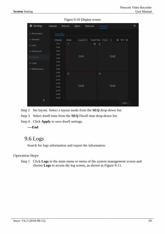
Figure 9-10 Display screen
Step 2 Set layout. Select a layout mode from the SEQ drop-down list.
Step 3 Select dwell time from the SEQ Dwell time drop-down list.
Step 4 Click Apply to save dwell settings.
----End
9.6 Logs Search for logs information and export the information.
Operation Steps
Step 1 Click Logs in the main menu or menu of the system management screen and
choose Logs to access the log screen, as shown in Figure 9-11.
Network Video Recorder
User Manual 9 System Setting
60 Issue: V4.2 (2018-08-15)
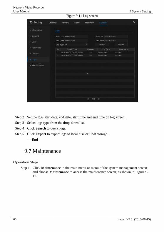
Figure 9-11 Log screen
Step 2 Set the logs start date, end date, start time and end time on log screen.
Step 3 Select logs type from the drop-down list.
Step 4 Click Search to query logs.
Step 5 Click Export to export logs to local disk or USB storage..
----End
9.7 Maintenance
Operation Steps
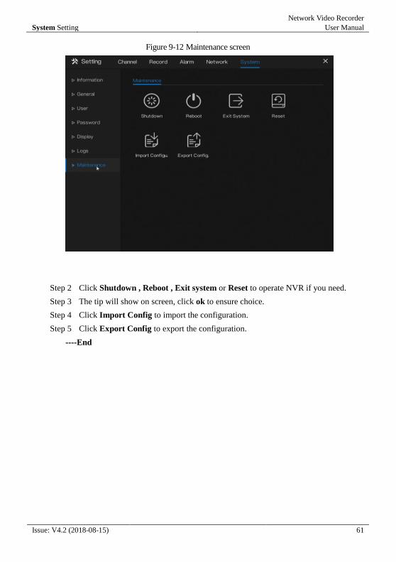
Step 1 Click Maintenance in the main menu or menu of the system management screen
and choose Maintenance to access the maintenance screen, as shown in Figure 9-
12.
System Setting
Network Video Recorder
User Manual
Issue: V4.2 (2018-08-15) 61
Figure 9-12 Maintenance screen
Step 2 Click Shutdown , Reboot , Exit system or Reset to operate NVR if you need.
Step 3 The tip will show on screen, click ok to ensure choice.
Step 4 Click Import Config to import the configuration.
Step 5 Click Export Config to export the configuration.
----End