Embed Size (px)
Citation preview

Network Intrusion Detection System Using
Neural Network Classification of Attack
Behavior
Omar Al-Jarrah Jordan University of Science and Technology, Irbid 22110, Jordan
Email: [email protected]
Ahmad Arafat Systems Engineer, Fortinet, United Arab Emirates
Email: [email protected]
Abstract—Intrusion Detection Systems (IDS) have become a
necessity in computer security systems because of the
increase in unauthorized accesses and attacks. Intrusion
Detection is a major component in computer security
systems that can be classified as Host-based Intrusion
Detection System (HIDS), which protects a certain host or
system and Network-based Intrusion detection system
(NIDS), which protects a network of hosts and systems. This
paper addresses Probes attacks or reconnaissance attacks,
which try to collect any possible relevant information in the
network. Network probe attacks have two types: Host
Sweep and Port Scan attacks. Host Sweep attacks determine
the hosts that exist in the network, while port scan attacks
determine the available services that exist in the network.
This paper uses an intelligent system to maximize the
recognition rate of network attacks by embedding the
temporal behavior of the attacks into a TDNN neural
network structure. The proposed system consists of five
modules: packet capture engine, preprocessor, pattern
recognition, classification, and monitoring and alert module.
Our system uses Principle Component neural network for
recognizing attacks and a classification module to classify
the attacks into host sweep or port scan. We have tested the
system in a real environment where it was able to detect all
attacks. In addition, the system was tested and compared
with SNORT using DARPA datasets. Our system
outperforms SNORT in terms of recognition rate and
throughput. In fact, our system can recognize all attacks in
a constant time.
Index Terms—intrusion detection systems, network probe
attack, host sweep, port scan, TDNN neural network
I. INTRODUCTION
Intrusion or threat can be defined as any deliberate
action that attempts unauthorized access, information
manipulation, or rendering the system unstable by
exploiting the existing vulnerabilities in the system.
These vulnerabilities could result from wrong practices
like weak security policy or software bugs like buffer
Manuscript received November 21, 2014; revised April 11, 2015.
overflows [1]. Instability of the system is mainly caused
by the Denial of Service (DOS) attacks, which attempt to
render certain service(s), such as, mail or web service,
unstable or to allow information disclosure. Intruders
might be system users with restricted privileges who
want to gain higher privileges, or might be internet users
who want to compromise the system or access sensitive
information [2].
Intrusion Detection Systems (IDSs) are used to detect
attacks against hosts or networks. There are two types of
IDSs: Host-based Intrusion Detection System (HIDS) and
Network-based Intrusion Detection System. HIDS
protects a certain host or system, while NIDS protects a
network of hosts and systems [3].
Despite the fact that many researchers attempted to
classify the computer threats and attacks into suitable
categories, there is still no adopted standard threats and
attacks classification [4] [5] [6]. The most widely used
classification for attacks in the research communities is
the one adopted by K. Kendall [7]. This classification
categorizes the computer attacks into:
• DOS Attacks: DOS attacks try to render the
system or certain service unstable.
• User to Root: it tries to gain the root or admin
privilege from normal user privilege.
• Remote to User: it tries to gain local account
privilege for unauthorized entity.
• Probes: In this type of attacks, the attacker tries to
collect any possible relevant information in the
network. In this class, two famous types of attacks
exist: Host Sweep and Port Scan Attacks. Host
Sweep attacks determine the hosts that exist in the
network, while port scan attacks determine the
available services that exist in the network.
The most well-known classification for IDSs is based
on the Approach of Intrusion Detection. There are two
common approaches, Anomaly detection and Misuse
detection [8]. Anomaly Detection works on two phases:
learning phase and detection phase. In the learning phase,
it builds a system profile for the normal system
parameters and states. While in the detection phase, the
1
Journal of Advances in Information Technology Vol. 6, No. 1, February 2015
doi: 10.12720/jait.6.1.1-82015 J. Adv. Inf. Technol. ©
system compares the current system parameters with ones
in the stored normal system profile, if they deviate in
some way, an alert of intrusion is reported to the
administrator or an appropriate action could be taken
[1][3][4]. The most common advantage of Anomaly
Detection is the ability to detect new and novel attacks.
Many Intrusion Detection Systems have been
implemented since the concept of Intrusion Detection has
appeared. One of the most important and open source
NIDSs is SNORT [9]. SNORT is a signature based IDS
in which the signatures are expressed through rules, so it
is a rule-based IDS. Its performance is high when
detecting content-based attacks. Its shortage appears in
discovering new and cyber-attacks. SNORT limits its
responsive action to report the attack to an administrator
console.
Another NIDS, which uses Anomaly Detection, is
Minnesota Intrusion Detection system (MINDS) [10].
MINDS uses three groups of features: features of
individual TCP connection, time-based features, and
connection-based features. MINDS is adaptive NIDS that
was able to detect intrusive activities, which SNORT
cannot detect. It uses statistical methods and AI
techniques in the detection process like Data Mining.
Some Intrusion Detection Systems model the attacks
using state transition diagrams [11]. NetSTAT is a
signature detection NIDS which describes the state of the
network using different parameters like active
connections, state of interactions, and the values of
network tables. Transitions between states occur when
interesting events happened, and the final state could be
safe or compromised.
Others have considered different issues in intrusion
detection systems such as took the high-speed
communication network [12]. These projects present new
concepts in Intrusion Detection like zero-copy-based
packet capture approach [12], which eliminates multiple
copies of the packet to minimize the memory overhead.
Other improvement was the enhanced packet filter to
maximize the number of non-important dropped packets
before entering the intrusion detection engine. In addition,
the efficient application protocol analysis is augmented
into NIDS to detect attacks that are related to specific
application protocol [4]. Some researchers were
interested in attacking and eluding the NIDS itself [13].
This paper uses neural networks as a data processing
technique. It shows that the temporal behavior of the
attack can be represented in neural network structure with
suitable design aspects. The detection process for the
stored signatures will be very effective and fast, and the
time taken to detect an attack will be constant. The
temporal attack behavior is hardwired in the neural
network structure to gain fast response and fast rate of
attack detection. The system is characterized by high rate
of attacks detection and low rate of false positives.
This system works in a universal IP plan, i.e. we do
not design the system for a range of addresses or a class
of addresses. The numerical values of features are not
important but the relations between inputs are the keys.
The system captures packets in real time using packet
capture engine, it uses multiprocessing to extract relevant
information from packets, neural networks that encode
the attack types and their temporal behavior to recognize
and identify port scan and host sweep attacks,
classification neural networks to classify the attacks, and
a monitoring and alert system to alert the system
administrator.
The rest of the paper is organized as follows. The
second section presents an overview of network probes.
The third section describes the proposed system structure
and components. Experimental results and discussion are
presented in the fourth section. Finally, the paper is
concluded in the fifth section.
II. NETWORK PROBES
This section discusses the behavior, importance, and
types of network probes. Network probes are very
important type of network attacks. They are regarded as
the first step to launch most of network attacks [14]. Any
network attack consists of three stages that usually occur
in sequence: network probe, attacks activity, and
footprint clearance. Without network probes, none of
most attacks can be launched. Network probes are known
as reconnaissance attacks [15] because their main
objective is to collect information about hosts and
network services running in the network.
A. Host Sweep Attacks
Network attacks usually start by performing network
discovery, which includes host sweep and port scan
attacks. Host sweep attack determines the live hosts in
the network; the attacker tries to find a gateway to start
with or enter from. Therefore, intruders will be searching
for weak points to compromise. Without this attack, the
intruder will not be able to launch most of the attacks
against network resources. There are three common types
of host sweep scan techniques: TCP ECHO, UDP ECHO,
and ICMP Sweep [16].
B. Port Scan Attacks
Port scanning tries to discover the running services on the victim machine, or tries to check the availability of certain service on the victim. It is well known that each network application running on the machine has a unique port number that it listens to such as port 80 for web browsing. By finding which services are running, a certain attack can be launched against the discovered service, e.g. a mail bomb attack can be launched against mail service to break it down. Port scan techniques presented in this paper have the following three temporal behaviors related to ports and hosts:
•
One host-
different
ports: The attacker scans
different
ports on a certain host, which is the
typical behavior of the port scan. The order of
ports is not important; scanning may be sequential
or random.
•
Different hosts-one port: The attacker scans
multiple hosts at the same time with the same port
number. This attack is launched against network
of hosts looking for hosts running a certain service
2
Journal of Advances in Information Technology Vol. 6, No. 1, February 2015
2015 J. Adv. Inf. Technol. ©
like DNS, SMTP, or HTTP. This type of scans is
more complex than the standard attack.
• Different hosts-different ports: The attacker scans
multiple hosts at the same time and each host is
possibly scanned with different port. This is an
advanced technique for port scanning, which that
tries to hide its activity by initiating random port
scans among random hosts. This attack is the most
complicated port scan.
In this paper, we will consider seven port scan attacks
including TCP SYN, TCP ACK, TCP SYN|ACK, TCP
FIN, TCP NULL, TCP XMAS, and UDP/ICMP Error.
III. NETWORK INTRUSION DETECTION SYSTEM USING
ATTACK BEHAVIOR CLASSIFICATION
This section describes different issues regarding the
structure, theory, and implementation of the system. This
system consists of 5 modules including packet capture
engine, preprocessor neural network, pattern recognition
neural network, classification neural network, and a
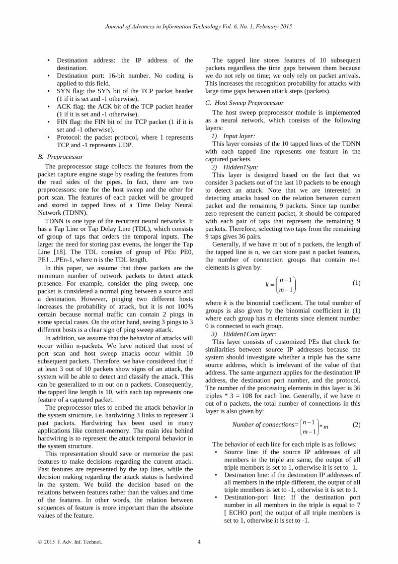
monitoring and alert module [17]. The block diagram of
the system and the relations between its components are
depicted in Fig. 1.
Figure1. System block diagram.
As shown in Fig. 1, the system continuously captures
the packets on the medium using the packet capture
engine module, which is also responsible for extracting
relevant features that are required in the subsequent
stages. The features are transferred to the next stage using
two PIPEs: one for the host sweep and the other for the
port scan. The packet capture engine writes the extracted
features to the PIPEs, which will be read by the next
component. The preprocessor reads these features from
the PIPEs and process them. The preprocessor consists of
two sub components: a host sweep preprocessor and a
port scan preprocessor. The function of the
preprocessor is to convert the sequential inputs, which
have a temporal relation to a set of patterns that can be
processed simultaneously, i.e. it rearranges the features of
the current and previous inputs to make it easier to detect
the attacks.
The preprocessing stage collects the features from the
packet capture engine stage by reading the features from
the read sides of the pipes. As a matter of fact, there are
two preprocessors: one for the host sweep and the other
for port scan. The features of each packet will be grouped
and stored in tapped lines of a Time Delay Neural
Network (TDNN).
TDNN is one type of the recurrent neural networks. It
has a Tap Line or Tap Delay Line (TDL), which consists
of group of taps that orders the temporal inputs. The
larger the need for storing past events, the longer the Tap
Line [18]. The TDL consists of group of Processing
Elements (PE): PE0, PE1…PEn-1, where n is the TDL
length.
The output of the preprocessor is directly connected to
the pattern recognition component, which is responsible
for detecting attacks using neural networks. The pattern
recognition consists of two components, one for host
sweep and the other for port scan. Because we have
different types of attacks, the classification component
classifies the detected attacks in the previous stage into
one of the different host sweep and port scan attack types.
Finally, this classification is reported to the alert and
monitoring module.
The alert and monitoring module is responsible for
alerting the system administrator about any existing
attacks or threats that exists in the network. The system
administrator is responsible for taking the appropriate
action.
A. Packet Capture Engine
Packet capture engine is the stage that is responsible
for capturing relevant traffic from the packet stream. It
uses the libpcap [7], which is a well-known capture
library that is used in many systems [7] [9]. The packet
capture engine captures ICMP, TCP, and UDP packets
that pass through a certain physical interface. Then, we
extract the relevant features that we need in the
recognition phase. For recognition of host sweep attacks,
the extracted features and their corresponding codes are:
• Source address: the Internet Protocol (IP) address
of the source.
• Destination address: the IP address of the
destination.
• Destination port: 16-bit number. No coding is
applied to this field.
• Protocol: describes the packet protocol, where 6, 4,
and 2 represent TCP, UDP, and ICMP protocols,
respectively.
The packet capture engine communicates with the
preprocessor module via two 1 KB two-ends PIPEs; one
PIPE for host sweep attacks and the other for port scan
attacks. The packet capture engine writes host sweep
features to the write-side of the pipe, while the
preprocessor reads these feature from the read-side of the
pipe. Similarly, it writes port scan features to the write
side of the corresponding pipe, while the preprocessor
reads from the other side.
For the port scan attacks, the following features are
extracted:
• Source address: the internet protocol (IP) address
of the source.
3
Journal of Advances in Information Technology Vol. 6, No. 1, February 2015
2015 J. Adv. Inf. Technol. ©
• Destination address: the IP address of the
destination.
• Destination port: 16-bit number. No coding is
applied to this field.
• SYN flag: the SYN bit of the TCP packet header
(1 if it is set and -1 otherwise).
• ACK flag: the ACK bit of the TCP packet header
(1 if it is set and -1 otherwise).
• FIN flag: the FIN bit of the TCP packet (1 if it is
set and -1 otherwise).
• Protocol: the packet protocol, where 1 represents
TCP and -1 represents UDP.
B. Preprocessor
The preprocessor stage collects the features from the
packet capture engine stage by reading the features from
the read sides of the pipes. In fact, there are two
preprocessors: one for the host sweep and the other for
port scan. The features of each packet will be grouped
and stored in tapped lines of a Time Delay Neural
Network (TDNN).
TDNN is one type of the recurrent neural networks. It
has a Tap Line or Tap Delay Line (TDL), which consists
of group of taps that orders the temporal inputs. The
larger the need for storing past events, the longer the Tap
Line [18]. The TDL consists of group of PEs: PE0,
PE1…PEn-1, where n is the TDL length.
In this paper, we assume that three packets are the
minimum number of network packets to detect attack
presence. For example, consider the ping sweep, one
packet is considered a normal ping between a source and
a destination. However, pinging two different hosts
increases the probability of attack, but it is not 100%
certain because normal traffic can contain 2 pings in
some special cases. On the other hand, seeing 3 pings to 3
different hosts is a clear sign of ping sweep attack.
In addition, we assume that the behavior of attacks will
occur within n-packets. We have noticed that most of
port scan and host sweep attacks occur within 10
subsequent packets. Therefore, we have considered that if
at least 3 out of 10 packets show signs of an attack, the
system will be able to detect and classify the attack. This
can be generalized to m out on n packets. Consequently,
the tapped line length is 10, with each tap represents one
feature of a captured packet.
The preprocessor tries to embed the attack behavior in
the system structure, i.e. hardwiring 3 links to represent 3
past packets. Hardwiring has been used in many
applications like content-memory. The main idea behind
hardwiring is to represent the attack temporal behavior in
the system structure.
This representation should save or memorize the past
features to make decisions regarding the current attack.
Past features are represented by the tap lines, while the
decision making regarding the attack status is hardwired
in the system. We build the decision based on the
relations between features rather than the values and time
of the features. In other words, the relation between
sequences of feature is more important than the absolute
values of the feature.
The tapped line stores features of 10 subsequent
packets regardless the time gaps between them because
we do not rely on time; we only rely on packet arrivals.
This increases the recognition probability for attacks with
large time gaps between attack steps (packets).
C. Host Sweep Preprocessor
The host sweep preprocessor module is implemented
as a neural network, which consists of the following
layers:
1) Input layer:
This layer consists of the 10 tapped lines of the TDNN
with each tapped line represents one feature in the
captured packets.
2) Hidden1Syn:
This layer is designed based on the fact that we
consider 3 packets out of the last 10 packets to be enough
to detect an attack. Note that we are interested in
detecting attacks based on the relation between current
packet and the remaining 9 packets. Since tap number
zero represent the current packet, it should be compared
with each pair of taps that represent the remaining 9
packets. Therefore, selecting two taps from the remaining
9 taps gives 36 pairs.
Generally, if we have m out of n packets, the length of
the tapped line is n, we can store past n packet features,
the number of connection groups that contain m-1
elements is given by:
1
1
m
nk (1)
where k is the binomial coefficient. The total number of
groups is also given by the binomial coefficient in (1)
where each group has m elements since element number
0 is connected to each group.
3) Hidden1Com layer:
This layer consists of customized PEs that check for
similarities between source IP addresses because the
system should investigate whether a triple has the same
source address, which is irrelevant of the value of that
address. The same argument applies for the destination IP
address, the destination port number, and the protocol.
The number of the processing elements in this layer is 36
triples * 3 = 108 for each line. Generally, if we have m
out of n packets, the total number of connections in this
layer is also given by:
Number of connections= mm
n*
1
1
(2)
The behavior of each line for each triple is as follows: • Source line: if the source IP addresses of all
members in the triple are same, the output of all
triple members is set to 1, otherwise it is set to -1. • Destination line: if the destination IP addresses of
all members in the triple different, the output of all triple members is set to -1, otherwise it is set to 1.
• Destination-port line: If the destination port
number in all members in the triple is equal to 7
[ ECHO port] the output of all triple members is
set to 1, otherwise it is set to -1.
4
Journal of Advances in Information Technology Vol. 6, No. 1, February 2015
2015 J. Adv. Inf. Technol. ©
• Protocol line: if the protocol of all members in the
triple is TCP (Code 6), the output of all triple
members is set to 4. If the protocol of all members
in the triple is UDP (Code 4), the output of all
triple members is set to 2. However, if the
protocol of all members in the triple is ICMP
(Code 2), the output of all triple members is set to
-2. Otherwise, it is set to -4.
4) Hidden2Syn
This component consists of a set of modular
connections that connect each triple in the hidden1com
layer to one PE in the output layer. This reduces the
number of PEs in the output layer to 108/3= 36 for each
feature. Generally, this layer connects each m-element
group to one PE in the output layer that has k PEs, where
k is the binomial coefficient in (1).
5) Output layer
This layer consists of linear PEs, which produce the
average values as follows:
3/3
1
i
i
iXY (3)
6) Where Y is the output and Xi is the input.
For example, the protocol line will result in an output
of 4 if all inputs are 4 (triple protocol is TCP), 2 if all
inputs are 2 (triple protocol is UDP), and -2 if all inputs
are -2 (triple protocol is ICMP). The same argument
applies to the source line, destination line, and destination
port line. Note that each PE in this layer represents the
status of the corresponding triple in its line. Generally,
the function of this layer is to produce the average value
of the inputs.
7) OutputSyn This component connects all outputs from all feature
lines to a buffer to be sent to the next module with a total of 36*4 = 144 PE. The 144 outputs are arranged in quadruples. Each quadruple consists of corresponding triple status from each feature line. For example, the first quadruple consists of the first source triple status, the first destination triple status, the first destination port triple status, and the first protocol triple status. Since the number of features that are used in the host sweep is 4, the number of processing elements in this stage can be generalized to:
Number of PE= 4*1
1
m
n (4)
D. Port Scan Preprocessor
The port scan preprocessor is implemented as a neural
network, which consists of the following layers:
1) Input layer
This layer is identical to the input layer in the host
sweep processor.
2) Hidden1Syn
This component is identical to the Hidden1Syn
component in the host sweep preprocessor.
3) Hidden1com layer
This layer is similar to the host sweep preprocessor
Hidden1com layer with small differences in the output
code of the lines. The behavior of the lines in this layer is
as follows:
• Source line: the same as in the host sweep
preprocessor.
• Destination line: the output is set to 1 when all the
members of the triple have the same destination IP
address. If the destinations are totally different, the
output is set to -1. Otherwise, the output is set to -
4.
• Destination-port line: the output is set to 1 when
all the members of the triple have the same
destination port address. If the destination port
numbers are totally different, the output is set to -1.
Otherwise the output is set to -4.
• SYN line: the output is set to 1 when all the
members of the triple have the same SYN flag. If
the SYN flags are totally different, the output is
set to -1. Otherwise the output is set to -4.
• ACK line: the same behavior as the SYN line, but
for the ACK flag.
• FIN line: the same behavior as the SYN line, but
for the FIN flag.
• TCP line: the output is set to 1 when the protocol
type in all members in the triple is TCP. If the
protocol in all members in the triple is UDP, the
output is set to -1. Otherwise, the output is set to -
4.
4) Hidden2Syn
This layer is identical to the host sweep preprocessor
Hidden2Syn component.
5) Output layer
This layer is identical to the host sweep preprocessor
output layer.
6) OutputSyn
This component is identical to the host sweep
preprocessor outputSyn component but with the number
of PEs in the output is set to 7*36 = 252. The 252 outputs
are arranged in groups of 7 elements each. Each group
consists of the corresponding triple statuses from each
feature line. For example, the first group consists of the
first source triple status, the first destination triple status,
the destination port triple status, the first SYN triple
status, the first ACK triple status, the first FIN triple
status, and the first protocol triple status. Since the
number of features that are used in the port scan is 7, the
number of processing elements in this stage can be
generalized to
Number of PE=
1
1
m
n * 7 (5)
This makes the system portable to any network with
any IP plan, since it does not depend on rang of IP
addresses or network address to work on.
E. Pattern Recognition Neural Networks
The pattern recognition neural networks use Principal
component analysis (PCA) to produce the principle
components, which differ between host sweep
recognition neural network and port scan recognition
neural network. PCA is a mathematical procedure that
5
Journal of Advances in Information Technology Vol. 6, No. 1, February 2015
2015 J. Adv. Inf. Technol. ©
transforms a number of (possibly) correlated variables
into a (smaller) number of uncorrelated variables called
principal components [19] [20]. The most common rule
that is used in PCA is Sangers which is called
Generalized Hebbian Algorithm (GHA) where the
principal components are extracted in order with respect
to the output unit ordering [21] [22].
For host sweep neural network, the number of
principle components is 4. While for port scan, the
number of principle components is 7. Note that the
number of principle components equals to the number of
features, which means that these features are the main
components that are needed to recognize these types of
attacks. Both of recognition networks, host sweep and
port scan recognition networks, take their input from the
preprocessor stage.
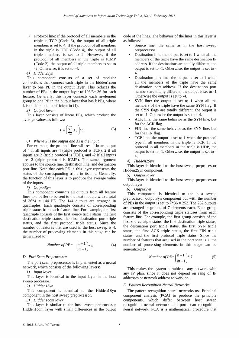
F. Host Sweep Pattern Recognition Neural Network
Recall that we identify 4 features or principle
components for host sweep recognition including IP
source address, destination address, destination port, and
protocol type. As the host sweep preprocessor stage has
144 outputs, which should feed the pattern recognition
stage, we need 144/4 = 36 recognition subsystem or units
to process the 36 quadruples. Fig. 2 illustrates the host
sweep pattern recognition neural network unit. This unit
has to be replicated 36 times to formulate the neural
network for all inputs. Generally, we need recognition
units to process all inputs, and the number of inputs in the
unit network will be equals to the number of used
features. Since an attack can be in any quadruple, all
quadruples are collected in the next stage for complete
attack recognition.
Figure. 2. Host sweep pattern recognition network unit.
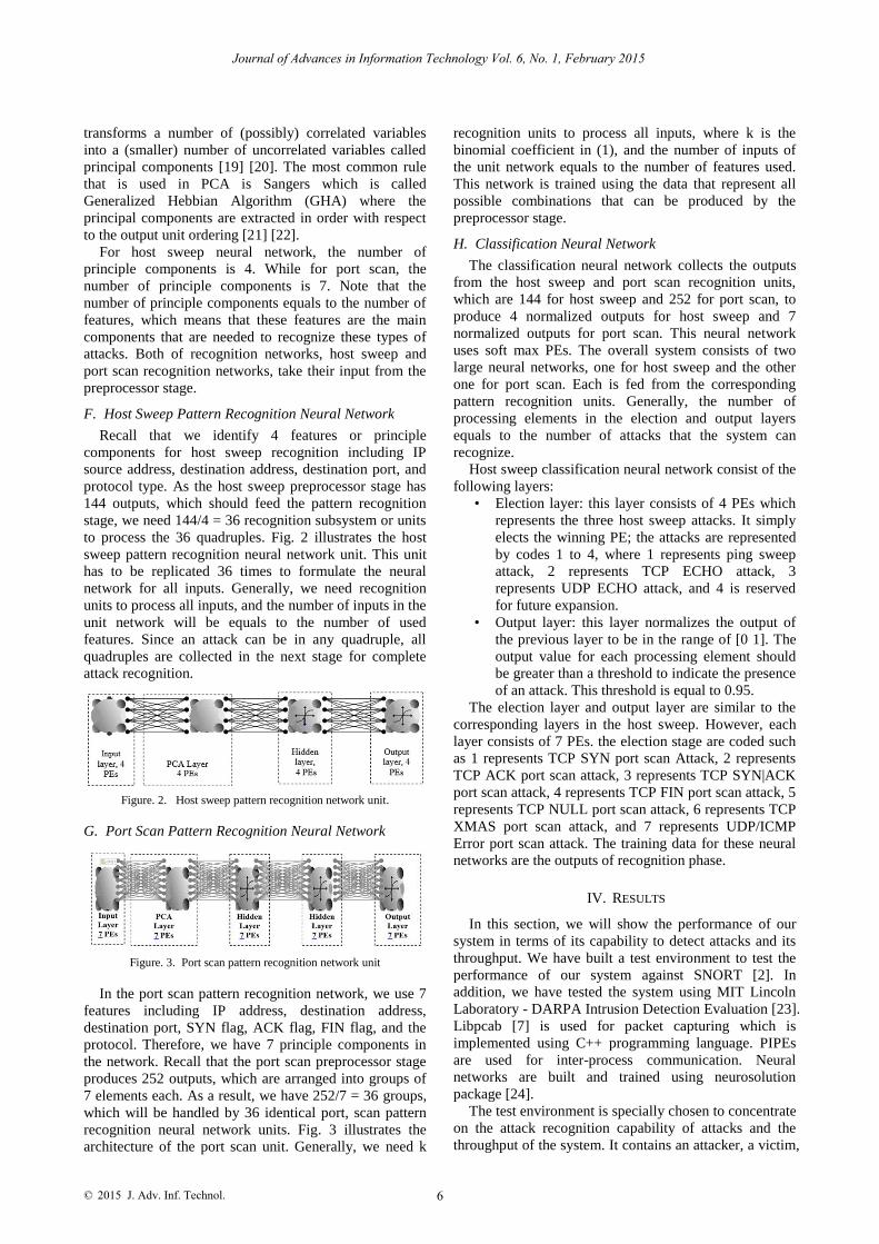
G. Port Scan Pattern Recognition Neural Network
Figure. 3. Port scan pattern recognition network unit
In the port scan pattern recognition network, we use 7
features including IP address, destination address,
destination port, SYN flag, ACK flag, FIN flag, and the
protocol. Therefore, we have 7 principle components in
the network. Recall that the port scan preprocessor stage
produces 252 outputs, which are arranged into groups of
7 elements each. As a result, we have 252/7 = 36 groups,
which will be handled by 36 identical port, scan pattern
recognition neural network units. Fig. 3 illustrates the
architecture of the port scan unit. Generally, we need k
recognition units to process all inputs, where k is the
binomial coefficient in (1), and the number of inputs of
the unit network equals to the number of features used.
This network is trained using the data that represent all
possible combinations that can be produced by the
preprocessor stage.
H. Classification Neural Network
The classification neural network collects the outputs
from the host sweep and port scan recognition units,
which are 144 for host sweep and 252 for port scan, to
produce 4 normalized outputs for host sweep and 7
normalized outputs for port scan. This neural network
uses soft max PEs. The overall system consists of two
large neural networks, one for host sweep and the other
one for port scan. Each is fed from the corresponding
pattern recognition units. Generally, the number of
processing elements in the election and output layers
equals to the number of attacks that the system can
recognize.
Host sweep classification neural network consist of the
following layers:
• Election layer: this layer consists of 4 PEs which
represents the three host sweep attacks. It simply
elects the winning PE; the attacks are represented
by codes 1 to 4, where 1 represents ping sweep
attack, 2 represents TCP ECHO attack, 3
represents UDP ECHO attack, and 4 is reserved
for future expansion.
• Output layer: this layer normalizes the output of
the previous layer to be in the range of [0 1]. The
output value for each processing element should
be greater than a threshold to indicate the presence
of an attack. This threshold is equal to 0.95.
The election layer and output layer are similar to the
corresponding layers in the host sweep. However, each
layer consists of 7 PEs. the election stage are coded such
as 1 represents TCP SYN port scan Attack, 2 represents
TCP ACK port scan attack, 3 represents TCP SYN|ACK
port scan attack, 4 represents TCP FIN port scan attack, 5
represents TCP NULL port scan attack, 6 represents TCP
XMAS port scan attack, and 7 represents UDP/ICMP
Error port scan attack. The training data for these neural
networks are the outputs of recognition phase.
IV. RESULTS
In this section, we will show the performance of our
system in terms of its capability to detect attacks and its
throughput. We have built a test environment to test the
performance of our system against SNORT [2]. In
addition, we have tested the system using MIT Lincoln
Laboratory - DARPA Intrusion Detection Evaluation [23].
Libpcab [7] is used for packet capturing which is
implemented using C++ programming language. PIPEs
are used for inter-process communication. Neural
networks are built and trained using neurosolution
package [24].
The test environment is specially chosen to concentrate
on the attack recognition capability of attacks and the
throughput of the system. It contains an attacker, a victim,
6
Journal of Advances in Information Technology Vol. 6, No. 1, February 2015
2015 J. Adv. Inf. Technol. ©

and the system. We use NMAP port scanner [25] to
generate attacks traffic. The port scan attacks are stored
in batch files for each attack. Thus, we have 24 batch
files, each perform a specific attack.
Attack name Temporal
behavior NIDSNN
Recognition Snort
Recognition
ICMP Host Sweep
- Yes Yes
TCP ECHO - Yes Yes (port scan)
UDP ECHO - Yes Yes (port scan)
TCP SYN Single Dst,
Diff-port Yes Yes
TCP SYN Diff-Dst, Single
port Yes Yes
TCP SYN Diff-Dst, Diff-
port Yes Yes
TCP ACK Single Dst, Diff-port
Yes No
TCP ACK Diff-Dst, Single
port Yes No
TCP ACK Diff-Dst, Diff-port
Yes No
TCP SYN|ACK Single Dst,
Diff-port Yes No
TCP SYN|ACK Diff-Dst, Single port
Yes No
TCP SYN|ACK Diff-Dst, Diff-
port Yes No
TCP FIN Single Dst, Diff-port
Yes Yes
TCP FIN Diff-Dst, Single
port Yes Yes
TCP FIN Diff-Dst, Diff-port
Yes Yes
TCP NULL Single Dst,
Diff-port Yes No
TCP NULL Diff-Dst, Single port
Yes No
TCP NULL Diff-Dst, Diff-
port Yes No
TCP XMAS Single Dst, Diff-port
Yes Yes
TCP XMAS Diff-Dst, Single
port Yes Yes
TCP XMAS Diff-Dst, Diff-port
Yes Yes
UDP Scan Single Dst,
Diff-port Yes Yes
UDP Scan Diff-Dst, Single port
Yes Yes
UDP Scan Diff-Dst, Diff-
port Yes Yes
In the first test, we compare our system with SNORT [9], which is a rule-based IDS. Both of snort and our system are loaded on the same machine as IDS. Both of snort and our system are loaded on the same machine as IDS. Table I illustrates the recognition capability of both SNORT and our system for all attacks that are considered in this paper. Our system in the table is denoted by Network Intrusion Detection System Using Neural networks (NIDSNN).
The results show that our system can recognize all types of attacks that are described in this paper regardless of the temporal behavior of the attack. We noted that SNORT missed some attacks like TCP ACK port scan. Since Snort is a rule based system, the augmentation of
the rules with new ones is applicable, which may make SNORT capable of recognizing the missed attacks.
The second test is using the standard off-line IDSs
evaluation data set of MIT Lincoln Laboratory - DARPA
Intrusion Detection Evaluation [23]. MIT has collected a
7-week traffic form a simulation network. Attack traffic
was shown in the network on the working hours. The
traffic files are stored in the tcpdump [26] format for the
7 weeks. Table II shows the test results after using the
DARPA data sets for host sweep and port scan attacks.
Each test is run on specific week and day. It is clear that
our system recognizes all attacks.
TABLE II. TYPE SIZES FOR CAMERA-READY PAPERS
Week # Day Attack
Name
Source Recognition
2 Monday Port Sweep 192.168.1.10 YES
2 Tuesday IP Sweep 135.13.216.191 YES
2 Friday NMAP 195.73.151.50 YES
3 Monday Port sweep 207.75.239.115 YES
3 Wednesday NMAP 202.72.1.77 YES
3 Wednesday IP sweep 202.77.162.213 YES
3 Friday NMAP 208.240.124.83 YES
4 Wednesday IPSweep 197.182.91.233 YES
4 Wednesday Port Sweep 194.27.251.21 YES
4 Thursday Port sweep 194.7.248.153 YES
4 Friday Port sweep 197.218.177.69 YES
Our tests show that the proposed system can deal with
different temporal behaviors of target attacks. These
results show a high recognition capability of the proposed
system, which is expected since the temporal behaviors
of the attacks are embedded in the structure of the
preprocessor neural network, i.e. the system is optimized
for these attacks patterns. Therefore, the recognition
capability will be high in spite of the temporal behaviors
of these attacks. DARPA test results show that the
proposed system can work with any IP plan with the
same efficiency. Our system is characterized by high
throughput because after the system is trained, it takes a
constant time to detect any attack.
V. CONCLUSIONS
Intrusion detection is an important issue that has
received a lot of attention in computer networks. This
paper uses TDDNN neural network to recognize the
temporal behavior of network attacks. Our system
captures packets in real time using a packet capture
engine that presents the packets to a preprocessing stage
using two pipes. The preprocessing stage extracts the
relevant features for port scan and host sweep attacks,
stores the features in a tapped line of a TDNN, and
produces outputs that represent possible attack behaviors
in a pre-specified number of packets. These outputs are
used by the pattern recognition neural networks to
recognize the attacks, which are classified, by the
classifier network to generate attack alerts. Once trained,
our system can produce immediate response to inputs in a
constant time; the recognition of attack presence can be
very fast regardless of the attack. DARPA data sets are
used to evaluate the systems in terms of recognition
capability and throughput. Test results show that our
7
Journal of Advances in Information Technology Vol. 6, No. 1, February 2015
TABLE I. NIDSNN AGAINST SNORT TEST RESULTS
2015 J. Adv. Inf. Technol. ©

system detects all types of attacks much faster than rule-
based systems such as SNORT.
REFERENCES
[1] S. Aurobindo, An Introduction to Intrusion Detection, ACM
crossroad Issue 2.4, April 1996.
[2] A. Jones and R. Sielken, Computer System Intrusion Detection: A Survey, University of Virginia, Computer Science Department
Technical Report, September 2000.
[3] P. Garcı´a-Teodoro, J. Dı´az-Verdejo, G. Macia -Ferna ndez, and E. Va´zquez, “Anomaly-based network intrusion detection:
Techniques, systems and challenges,” Computer and Security, vol.
28, pp. 18-28, 2009. [4] P. Kazienko and P. Dorosz. (April 7, 2003) Intrusion Detection
Systems (IDS) Part I - network intrusions; attack symptoms; IDS tasks; and IDS architecture. [Online]. Available:
http://www.windowsecurity.com
[5] D. Hollingworth, “Towards threat, attack, and vulnerability taxonomies,” in Proc. 44th IFIP WG 10.4 Meeting, Monterey, CA,
USA, June 25-29, 2003
[6] F. Abdollah, M. Mas’ud, S. Sahib, A. Yaacob, R. Yusof, and S. Selamat, “Host based detection approach using time based module
for fast attack detection behavior,” Lecture Notes in Electrical
Engineering, vol. 157, pp. 163-171, 2012. [7] Winpcap: packet capture tool. [Online]. Available:
http://www.winpcap.org
[8] R. Chen, K. Cheng, and C. Hsieh, “Using rough set and support vector machine for network intrusion detection,” International
Journal of Network Security & Its Applications, vol. 1, no. 1,
April 2009. [9] SNORT Network Intrusion Detection System. [Online]. Available:
http://www.snort.org
[10] Minnesota Intrusion Detection System (MINDS). (2006). [Online]. Available: http://www.cs.umn.edu/research/minds
[11] V. Kemmerer, “NetSTAT: A network-based intrusion detection
system,” Computer Security, vol. 7, no. 1, pp. 37-71, 1999. [12] W. Yang, B. Fang, B. Liu, and H. Zhang, “Intrusion detection
system for high speed network,” Computer Communications, vol.
27, no. 13, pp. 1288-1294. August 2004. [13] T. Ptacek, “Insertion, evasion and denial of service: Eluding
network intrusion detection,” Secure Network Inc., January 1998.
[14] R. Rswatcher, A Port Scanning Detector, M.S. thesis, Florida State University, 1999
[15]
J. Jung, V. Paxson, A. Berger, and H. Balakrishnan, “Fast
portscan detection using sequential hypothesis testing,”
in Proc.
IEEE Symposium on Security and Privacy 2004,. Oakland, CA; May 2004.
[16]
Dethy. (Oct. 16, 2002). Whitepaper: Examining port scan
methods-Analyzing Audible Techniques. [Online]. Available: http://www.windowsecurity.com
[17]
O. Al-Jarrah and A. Arafat, “Network intrusion detection system
using attack behavior classification,” in Proc. the International Conference on Information and Communication Systems, Irbid,
Jordan, April 2014.
[18]
R. Schalkoff, Artificial Neural Networks, McGraw-Hill, 1997. [19]
K. Diamantras and S. Kung, Principal Component Neural
Networks, John Wiley and Sons, 1996.
[20]
E. Oja, “Unsupervised learning in neural computation,”
Theoretical Computer Science, vol. 287, pp. 187 – 207, 2002.
[21]
J. Principe, N. Euliano, and W. Lefebvre, Neural and Adaptive
Systems: Fundamentals through Simulations, John Wiley and Sons, 2000.
[22]
T. Sanger, “Optimal unsupervised learning in a single-layer neural
network,” Neural Networks, vol. 2, pp. 459–473, 1989. [23]
Lincolin Laboratory. Massachusetts Institute of Technology.
[Online]. Available:
http://www.ll.mit.edu/IST/ideval/data/data_index.html [24]
Neuro Solutions: Neural network building and training tool.
[Online]. Available: http://www.neurosolutions.com
[25]
NMAP: advanced port scanner. [Online]. Available: http://www.insecure.org/nmap
[26]
TCPDUMP: windows packet capture engine. [Online]. Available:
http://www.tcpdump.org
Omar M. Al-Jarrah
is a professor of Computer Engineering at Jordan
University of Science and Technology (JUST), Irbid, Jordan. He received the B.Sc. in Electrical Engineering from JUST in 1991, M.Sc.
and Ph.D. in Electrical and Computer Engineering from Ohio State University in 1994 and 1996, respectively. His research interests
include Artificial Intelligence, Computer Networks, and eLearning. Prof.
Al-Jarrah has published 62 technical papers in well-reputed
international journals and conferences. During his career, he has supervised more than 100 graduate and undergraduate students.
Ahmad Arafat
is a senior systems Engineer at Fortinet, United Arab
Emirates. He received his M.Sc. in Computer Engineering from Jordan
University of Science and Technology (JUST), Irbid, Jordan.
8
Journal of Advances in Information Technology Vol. 6, No. 1, February 2015
2015 J. Adv. Inf. Technol. ©