Embed Size (px)
Citation preview

0
Network Dome Camera
Quick Start Guide
Network Dome Camera·Quick Start Guide
1
1 Quick Start Guide
COPYRIGHT © 2017 Hangzhou Hikvision Digital Technology Co., Ltd.
ALL RIGHTS RESERVED.
Any and all information, including, among others, wordings, pictures,
graphs are the properties of Hangzhou Hikvision Digital Technology
Co., Ltd. or its subsidiaries (hereinafter referred to be “Hikvision”).
This user manual (hereinafter referred to be “the Manual”) cannot
be reproduced, changed, translated, or distributed, partially or
wholly, by any means, without the prior written permission of
Hikvision. Unless otherwise stipulated, Hikvision does not make any
warranties, guarantees or representations, express or implied,
regarding to the Manual.
About this Manual
This Manual is applicable to 21xx Network Camera.
The Manual includes instructions for using and managing the
product. Pictures, charts, images and all other information
hereinafter are for description and explanation only. The
information contained in the Manual is subject to change, without
notice, due to firmware updates or other reasons. Please find the
latest version in the company website
(http://overseas.hikvision.com/en/).
Please use this user manual under the guidance of professionals.
Trademarks Acknowledgement
and other Hikvision’s trademarks and logos are the
properties of Hikvision in various jurisdictions. Other trademarks and
Network Dome Camera·Quick Start Guide
2
2 logos mentioned below are the properties of their respective
owners.
Legal Disclaimer
TO THE MAXIMUM EXTENT PERMITTED BY APPLICABLE LAW, THE
PRODUCT DESCRIBED, WITH ITS HARDWARE, SOFTWARE AND
FIRMWARE, IS PROVIDED “AS IS”, WITH ALL FAULTS AND ERRORS,
AND HIKVISION MAKES NO WARRANTIES, EXPRESS OR IMPLIED,
INCLUDING WITHOUT LIMITATION, MERCHANTABILITY,
SATISFACTORY QUALITY, FITNESS FOR A PARTICULAR PURPOSE, AND
NON-INFRINGEMENT OF THIRD PARTY. IN NO EVENT WILL
HIKVISION, ITS DIRECTORS, OFFICERS, EMPLOYEES, OR AGENTS BE
LIABLE TO YOU FOR ANY SPECIAL, CONSEQUENTIAL, INCIDENTAL, OR
INDIRECT DAMAGES, INCLUDING, AMONG OTHERS, DAMAGES FOR
LOSS OF BUSINESS PROFITS, BUSINESS INTERRUPTION, OR LOSS OF
DATA OR DOCUMENTATION, IN CONNECTION WITH THE USE OF
THIS PRODUCT, EVEN IF HIKVISION HAS BEEN ADVISED OF THE
POSSIBILITY OF SUCH DAMAGES.
REGARDING TO THE PRODUCT WITH INTERNET ACCESS, THE USE OF
PRODUCT SHALL BE WHOLLY AT YOUR OWN RISKS. HIKVISION SHALL
NOT TAKE ANY RESPONSIBILITIES FOR ABNORMAL OPERATION,
PRIVACY LEAKAGE OR OTHER DAMAGES RESULTING FROM CYBER
ATTACK, HACKER ATTACK, VIRUS INSPECTION, OR OTHER INTERNET
SECURITY RISKS; HOWEVER, HIKVISION WILL PROVIDE TIMELY
TECHNICAL SUPPORT IF REQUIRED.
SURVEILLANCE LAWS VARY BY JURISDICTION. PLEASE CHECK ALL
RELEVANT LAWS IN YOUR JURISDICTION BEFORE USING THIS
PRODUCT IN ORDER TO ENSURE THAT YOUR USE CONFORMS THE
Network Dome Camera·Quick Start Guide
3
3 APPLICABLE LAW. HIKVISION SHALL NOT BE LIABLE IN THE EVENT
THAT THIS PRODUCT IS USED WITH ILLEGITIMATE PURPOSES.
IN THE EVENT OF ANY CONFLICTS BETWEEN THIS MANUAL AND THE
APPLICABLE LAW, THE LATER PREVAILS.
Regulatory Information
For products that support Wi-Fi or cellular data:
(Marked with a “W”, “GLT”, “GLE”, “GLF”, “GE”, “GT” or “GW” in the
Part C of a product model.
Product Model Example: Part A-Part B-Part C. Part C is optional.)
FCC Information
Please take attention that changes or modification not expressly
approved by the party responsible for compliance could void the
user’s authority to operate the equipment.
FCC compliance: This equipment has been tested and found to
comply with the limits for a Class B digital device, pursuant to part
15 of the FCC Rules. These limits are designed to provide reasonable
protection against harmful interference in a residential installation.
This equipment generates, uses and can radiate radio frequency
energy and, if not installed and used in accordance with the
instructions, may cause harmful interference to radio
communications. However, there is no guarantee that interference
will not occur in a particular installation. If this equipment does
cause harmful interference to radio or television reception, which
can be determined by turning the equipment off and on, the user is
encouraged to try to correct the interference by one or more of the
following measures:
—Reorient or relocate the receiving antenna.
Network Dome Camera·Quick Start Guide
4
4 —Increase the separation between the equipment and receiver.
—Connect the equipment into an outlet on a circuit different from
that to which the receiver is connected.
—Consult the dealer or an experienced radio/TV technician for help.
This equipment should be installed and operated with a minimum
distance 20cm between the radiator and your body.
FCC Conditions
This device complies with part 15 of the FCC Rules. Operation is
subject to the following two conditions:
1. This device may not cause harmful interference.
2. This device must accept any interference received, including
interference that may cause undesired operation.
EU Conformity Statement
This product and - if applicable - the supplied
accessories too are marked with "CE" and comply
therefore with the applicable harmonized European
standards listed under the Radio Equipment Directive 2014/53/EU,
the EMC Directive 2014/30/EU, the RoHS Directive 2011/65/EU.
2012/19/EU (WEEE directive): Products marked
with this symbol cannot be disposed of as unsorted
municipal waste in the European Union. For proper
recycling, return this product to your local supplier
upon the purchase of equivalent new equipment, or dispose of it at
designated collection points. For more information see:
www.recyclethis.info

Network Dome Camera·Quick Start Guide
5
5 2006/66/EC (battery directive): This product
contains a battery that cannot be disposed of as
unsorted municipal waste in the European Union.
See the product documentation for specific battery
information. The battery is marked with this symbol,
which may include lettering to indicate cadmium (Cd), lead (Pb), or
mercury (Hg). For proper recycling, return the battery to your
supplier or to a designated collection point. For more information
see: www.recyclethis.info
Industry Canada ICES-003 Compliance
This device meets the CAN ICES-3 (B)/NMB-3(B) standards
requirements.
This device complies with Industry Canada licence-exempt RSS
standard(s). Operation is subject to the following two conditions:
(1) this device may not cause interference, and
(2) this device must accept any interference, including interference
that may cause undesired operation of the device.
Le présent appareil est conforme aux CNR d'Industrie Canada
applicables aux appareils radioexempts de licence. L'exploitation est
autorisée aux deux conditions suivantes :
(1) l'appareil ne doit pas produire de brouillage, et
(2) l'utilisateur de l'appareil doit accepter tout brouillage
radioélectrique subi, même si le brouillage est susceptible d'en
compromettre le fonctionnement.
Under Industry Canada regulations, this radio transmitter may only
operate using an antenna of a type and maximum (or lesser) gain
approved for the transmitter by Industry Canada. To reduce potential
Network Dome Camera·Quick Start Guide
6
6 radio interference to other users, the antenna type and its gain
should be so chosen that the equivalent isotropically radiated power
(e.i.r.p.) is not more than that necessary for successful
communication.
Conformément à la réglementation d'Industrie Canada, le présent
émetteur radio peut fonctionner avec une antenne d'un type et d'un
gain maximal (ou inférieur) approuvé pour l'émetteur par Industrie
Canada. Dans le but de réduire les risques de brouillage
radioélectrique à l'intention des autres utilisateurs, il faut choisir le
type d'antenne et son gain de sorte que la puissance isotrope
rayonnée équivalente (p.i.r.e.) ne dépasse pas l'intensité nécessaire à
l'établissement d'une communication satisfaisante.
This equipment should be installed and operated with a minimum
distance 20cm between the radiator and your body.
Cet équipement doit être installé et utilisé à une distance minimale
de 20 cm entre le radiateur et votre corps.
For products that do not support Wi-Fi or cellular data:
FCC Information
Please take attention that changes or modification not expressly
approved by the party responsible for compliance could void the
user’s authority to operate the equipment.
FCC compliance: This equipment has been tested and found to
comply with the limits for a Class B digital device, pursuant to part
15 of the FCC Rules. These limits are designed to provide reasonable
protection against harmful interference in a residential installation.
This equipment generates, uses and can radiate radio frequency

Network Dome Camera·Quick Start Guide
7
7 energy and, if not installed and used in accordance with the
instructions, may cause harmful interference to radio
communications. However, there is no guarantee that interference
will not occur in a particular installation. If this equipment does
cause harmful interference to radio or television reception, which
can be determined by turning the equipment off and on, the user is
encouraged to try to correct the interference by one or more of the
following measures:
—Reorient or relocate the receiving antenna.
—Increase the separation between the equipment and receiver.
—Connect the equipment into an outlet on a circuit different from
that to which the receiver is connected.
—Consult the dealer or an experienced radio/TV technician for help.
FCC Conditions
This device complies with part 15 of the FCC Rules. Operation is
subject to the following two conditions:
1. This device may not cause harmful interference.
2. This device must accept any interference received, including
interference that may cause undesired operation.
EU Conformity Statement
This product and - if applicable - the supplied
accessories too are marked with "CE" and comply
therefore with the applicable harmonized European
standards listed under the EMC Directive 2014/30/EU, the RoHS
Directive 2011/65/EU.

Network Dome Camera·Quick Start Guide
8
8 2012/19/EU (WEEE directive): Products marked
with this symbol cannot be disposed of as unsorted
municipal waste in the European Union. For proper
recycling, return this product to your local supplier
upon the purchase of equivalent new equipment, or dispose of it at
designated collection points. For more information see:
www.recyclethis.info
2006/66/EC (battery directive): This product
contains a battery that cannot be disposed of as
unsorted municipal waste in the European Union.
See the product documentation for specific battery
information. The battery is marked with this symbol,
which may include lettering to indicate cadmium (Cd), lead (Pb), or
mercury (Hg). For proper recycling, return the battery to your
supplier or to a designated collection point. For more information
see: www.recyclethis.info
Industry Canada ICES-003 Compliance
This device meets the CAN ICES-3 (B)/NMB-3(B) standards
requirements.
Safety Instruction
These instructions are intended to ensure that user can use the
product correctly to avoid danger or property loss.
The precaution measure is divided into “Warnings” and “Cautions”
Warnings: Serious injury or death may occur if any of the warnings
are neglected. Cautions: Injury or equipment damage may occur if any of the
cautions are neglected.

Network Dome Camera·Quick Start Guide
9
9
Warnings ● In the use of the product, you must be in strict compliance with
the electrical safety regulations of the nation and region. Please
refer to technical specifications for detailed information.
● Input voltage should meet both the SELV (Safety Extra Low
Voltage) and the Limited Power Source with 12 VDC according
to the IEC60950-1 standard. Please refer to technical
specifications for detailed information.
● Do not connect several devices to one power adapter as
adapter overload may cause over-heating or a fire hazard.
● Please make sure that the plug is firmly connected to the power
socket. When the product is mounted on wall or ceiling, the
device shall be firmly fixed.
● If smoke, odor or noise rise from the device, turn off the power
at once and unplug the power cable, and then please contact
the service center.
Warnings Follow these
safeguards to prevent
serious injury or death.
Cautions Follow these
precautions to prevent
potential injury or material
damage.

Network Dome Camera·Quick Start Guide
10
10 ● Proper configuration of all passwords and other security
settings is the responsibility of the installer and/or end-user.
Cautions ● Make sure the power supply voltage is correct before using the
camera.
● Do not drop the camera or subject it to physical shock.
● Do not touch sensor modules with fingers. If cleaning is
necessary, use clean cloth with a bit of ethanol and wipe it
gently. If the camera will not be used for an extended period,
please replace the lens cap to protect the sensor from dirt.
● Do not aim the camera at the sun or extra bright places.
Blooming or smearing may occur otherwise (which is not a
malfunction), and affect the endurance of sensor at the same
time.
● The sensor may be burned out by a laser beam, so when any
laser equipment is in using, make sure that the surface of
sensor will not be exposed to the laser beam.
● Do not place the camera in extremely hot, cold (the operating
temperature shall be -30°C to +60°C, dusty or damp locations,
and do not expose it to high electromagnetic radiation.
● To avoid heat accumulation, good ventilation is required for
operating environment.
● Keep the camera away from liquid while in use.
Network Dome Camera·Quick Start Guide
11
11 ● While in delivery, the camera shall be packed in its original
packing, or packing of the same texture.
● Regular part replacement: a few parts (e.g. electrolytic
capacitor) of the equipment shall be replaced regularly
according to their average enduring time. The average time
varies because of differences between operating environment
and using history, so regular checking is recommended for all
the users. Please contact with your dealer for more details.
● Improper use or replacement of the battery may result in
hazard of explosion. Replace with the same or equivalent type
only. Dispose of used batteries according to the instructions
provided by the battery manufacturer.
● If the product does not work properly, please contact your
dealer or the nearest service center. Never attempt to
disassemble the camera yourself. (We shall not assume any
responsibility for problems caused by unauthorized repair or
maintenance.)
0505031071113

Network Dome Camera·Quick Start Guide
12
12
Table of Contents 1 Appearance Description ............................................................... 13
Type I ............................................................................ 13 1.1
Type II ........................................................................... 14 1.2
Type III .......................................................................... 16 1.3
Type IV .......................................................................... 18 1.4
Type V ........................................................................... 19 1.5
2 Installation .................................................................................... 22 Memory Card Installation .............................................. 23 2.1
Ceiling Mounting ........................................................... 24 2.2
Mounting with Brackets ................................................ 29 2.3
(Optional) Network Cable Waterproof Jacket Installation40 2.4
3 Set the Network Camera over the LAN ......................................... 43 Wiring ........................................................................... 43 3.1
Activate the Camera ...................................................... 44 3.2
Modify the IP Address ................................................... 47 3.3
4 Access via Web Browser ............................................................... 50 5 Operate via Hik-Connect App ....................................................... 52
5.1 Enable Hik-Connect Service on Camera ......................... 52 5.2 Hik-Connect Setup ........................................................ 55 5.3 Add Camera to Hik-Connect .......................................... 55 5.4 Initialize the Memory Card ............................................ 57

Network Dome Camera·Quick Start Guide
13
13
1 Appearance Description
There are five types of camera appearance for this series of camera
according to the different models.
Type I 1.1
12
3
4
789
10
56
Overview of Type I Camera Figure 1-1
Description of Type I Camera Table 1-1
No. Description No. Description
1 Mounting Base 2 Horizontal Stand
3 Vertical Stand 4 Bubble
Network Dome Camera·Quick Start Guide
14
14
No. Description No. Description
5 Network Interface 6 Power Interface
7 IR LED 8 Lens
9 Black Liner 10 Safety Rope
Note:
Press RESET about 10s when the camera is powering on or rebooting
to restore the default settings, including the user name, password, IP
address, port No., etc.
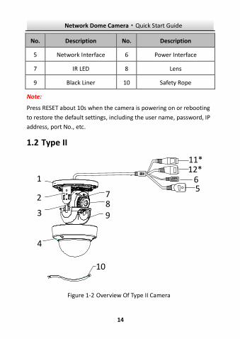
Type II 1.2
51
2
3
4
9
6
78
10
11*12*
Overview Of Type II Camera Figure 1-2
Network Dome Camera·Quick Start Guide
15
15
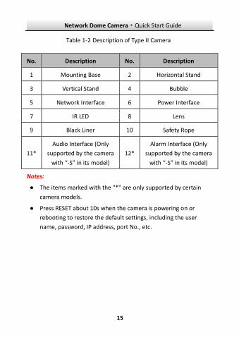
Description of Type II Camera Table 1-2
No. Description No. Description
1 Mounting Base 2 Horizontal Stand
3 Vertical Stand 4 Bubble
5 Network Interface 6 Power Interface
7 IR LED 8 Lens
9 Black Liner 10 Safety Rope
11*
Audio Interface (Only
supported by the camera
with “-S” in its model)
12*
Alarm Interface (Only
supported by the camera
with “-S” in its model)
Notes:
● The items marked with the "*" are only supported by certain
camera models.
● Press RESET about 10s when the camera is powering on or
rebooting to restore the default settings, including the user
name, password, IP address, port No., etc.

Network Dome Camera·Quick Start Guide
16
16
Type III 1.3
5
7
6
8
1
4
3*
DC12VIN
2*
9
10
Overview Of Type III Camera Figure 1-3

Network Dome Camera·Quick Start Guide
17
17
Description of Type III Camera Table 1-3
No. Description
1 Power supply interface (12 VDC)
2* Audio input and output interface
3* Alarm input and output interface
4 RJ45 self-adaptive network interface (PoE)
5 Mounting base
6 Black liner
7 Lens
8 Bubble
9 Memory card slot
10 Reset button
Note:
● The items marked with the "*" are only supported by certain
camera models.
● Press RESET about 10s when the camera is powering on or
rebooting to restore the default settings, including the user
name, password, IP address, port No., etc.
Network Dome Camera·Quick Start Guide
18
18
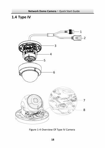
Type IV 1.4
5
6
1
4
3
2
7
8
Overview Of Type IV Camera Figure 1-4

Network Dome Camera·Quick Start Guide
19
19
Description of Type IV Camera Table 1-4
No. Description
1 RJ45 self-adaptive network interface (supports
PoE)
2 HDMI
3 Mounting base
4 Black liner
5 Lens
6 Bubble
7 Memory card slot
8 Reset button
Note:
Press RESET about 10s when the camera is powering on or rebooting
to restore the default settings, including the user name, password, IP
address, port No., etc.
Type V 1.5
Network Dome Camera·Quick Start Guide
20
20
1
2
3
6
7
8
9
45
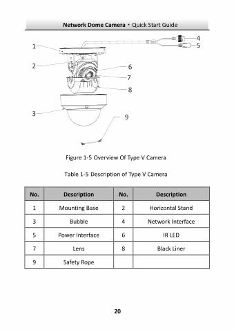
Overview Of Type V Camera Figure 1-5
Description of Type V Camera Table 1-5
No. Description No. Description
1 Mounting Base 2 Horizontal Stand
3 Bubble 4 Network Interface
5 Power Interface 6 IR LED
7 Lens 8 Black Liner
9 Safety Rope

Network Dome Camera·Quick Start Guide
21
21 Note:
Press RESET about 10s when the camera is powering on or rebooting
to restore the default settings, including the user name, password, IP
address, port No., etc.

Network Dome Camera·Quick Start Guide
22
22
2 Installation
Before you start:
● Make sure the device in the package is in good condition and all
the assembly parts are included.
● The standard power supply is 12 VDC or PoE (802.3 af), please
make sure your power supply matches with your camera.
● Make sure all the related equipment is power-off during the
installation.
● Check the specification of the products for the installation
environment.
● Make sure that the wall is strong enough to withstand four
times the weight of the camera and the bracket.
For the camera that supports IR, you are required to pay attention to
the following precautions to prevent IR reflection:
● Dust or grease on the dome cover will cause IR reflection.
Please do not remove the dome cover film until the installation
is finished. If there is dust or grease on the dome cover, clean
the dome cover with clean soft cloth and isopropyl alcohol.
● Make sure that there is no reflective surface too close to the
camera lens. The IR light from the camera may reflect back into
the lens causing reflection.
● The foam ring around the lens must be seated flush against the
inner surface of the bubble to isolate the lens from the IR LEDS.
Fasten the dome cover to camera body so that the foam ring
and the dome cover are attached seamlessly.

Network Dome Camera·Quick Start Guide
23
23
Memory Card Installation 2.1
For camera models that support memory card as local storage, you
can follow the steps to mount and unmount the memory card.
This camera series shares a similar structure, type III camera is used
for demonstration.
Steps:
1. Loosen the screws on the bubble. Remove the bubble to expose
the memory card slot.
Remove Bubble Figure 2-1
Notes:
● In case of losing, screws on bubble cannot be screwed out
thoroughly.
● The bubble is fastened to the camera with a safety rope.

Network Dome Camera·Quick Start Guide
24
24 2. Find the memory card slot to insert the memory card.
Insert Memory Card Figure 2-2
3. (Optional) To unmount the memory card, push to get it ejected.
Ceiling Mounting 2.2
This camera series shares a similar structure, type III camera is used
for demonstration.
Steps:
1. Paste the drill template to desired mounting place.
2. Drill the screw holes on the ceiling according to the drill
template.
Network Dome Camera·Quick Start Guide
25
25
1
1
1
A
Drill TemplateHole A: for cables routed through the ceiling
Screw hole 1: for Mounting Base
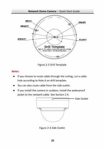
Drill Template Figure 2-3
Notes:
● If you choose to route cable through the ceiling, cut a cable
hole according to Hole A on drill template.
● You can also route cable from the side outlet.
● If you install the camera in outdoor, install the waterproof
jacket to the network cable. See Section 2.4.
Side Outlet Figure 2-4
Side Outlet
Network Dome Camera·Quick Start Guide
26
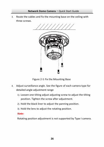
26 3. Route the cables and fix the mounting base on the ceiling with
three screws.
Fix the Mounting Base Figure 2-5
4. Adjust surveillance angle. See the figure of each camera type for
detailed angle adjustment range
1). Loosen one tilting adjust adjusting screw to adjust the tilting
position. Tighten the screw after adjustment.
2). Hold the black liner to adjust the panning position.
3). Hold the lens to adjust the rotating position.
Note:
Rotating position adjustment is not supported by Type I camera.

Network Dome Camera·Quick Start Guide
27
27
Angle Adjustment of Type I Camera Figure 2-6
Tilting Adjust Screw
Rotate: 0° to 355°
Pan:0° to 355°
Tilt: 0° to 75°
Angle Adjustment of Type II Camera Figure 2-7
0°~360°
0°~65°
Tilting AdjustScrew

Network Dome Camera·Quick Start Guide
28
28
Angle Adjustment of Type III Camera Figure 2-8
5. Install the bubble back to the camera.
Install Bubble Figure 2-9

Network Dome Camera·Quick Start Guide
29
29
Mounting with Brackets 2.3
This camera series supports mounting with wall mounting bracket,
pendant mounting bracket, and incline mounting bracket. We take
Type III camera as the demonstration example.
Wall Mounting 2.3.1
The wall mounting bracket is not included in the package. You need
to prepare one, if you adopt this mounting type.
Steps:
1. Mark the screw holes on desired mounting place.
HoleHole
HoleHole
Mark Screw Hole Figure 2-10
Network Dome Camera·Quick Start Guide
30
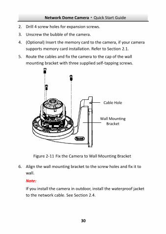
30 2. Drill 4 screw holes for expansion screws.
3. Unscrew the bubble of the camera.
4. (Optional) Insert the memory card to the camera, if your camera
supports memory card installation. Refer to Section 2.1.
5. Route the cables and fix the camera to the cap of the wall
mounting bracket with three supplied self-tapping screws.
Wall Mounting Bracket
Cable Hole
Fix the Camera to Wall Mounting Bracket Figure 2-11
6. Align the wall mounting bracket to the screw holes and fix it to
wall.
Note:
If you install the camera in outdoor, install the waterproof jacket
to the network cable. See Section 2.4.

Network Dome Camera·Quick Start Guide
31
31
Fix the Wall Mounting Bracket to Wall Figure 2-12
7. Adjust surveillance angle of camera. Refer to Step 4 in Section
2.2.
8. Install the bubble back to the camera.
Figure 2-13 Install the Bubble
Network Dome Camera·Quick Start Guide
32
32
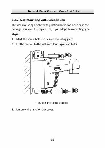
Wall Mounting with Junction Box 2.3.2
The wall mounting bracket with junction box is not included in the
package. You need to prepare one, if you adopt this mounting type.
Steps:
1. Mark the screw holes on desired mounting place.
2. Fix the bracket to the wall with four expansion bolts.
Fix the Bracket Figure 2-14
3. Unscrew the junction box cover.
Network Dome Camera·Quick Start Guide
33
33
Cover
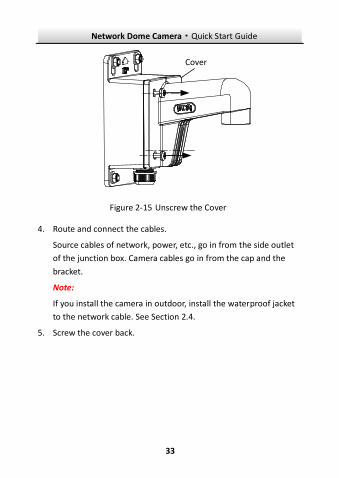
Unscrew the Cover Figure 2-15
4. Route and connect the cables.
Source cables of network, power, etc., go in from the side outlet
of the junction box. Camera cables go in from the cap and the
bracket.
Note:
If you install the camera in outdoor, install the waterproof jacket
to the network cable. See Section 2.4.
5. Screw the cover back.

Network Dome Camera·Quick Start Guide
34
34
Source CableCamera Cable
Cable Routing Figure 2-16
6. Unscrew the bubble of the camera.
7. (Optional) Insert the memory card to the camera, if your camera
supports memory card installation. Refer to Section 2.1.
8. Fix the camera to the cap of the wall mounting bracket with
three supplied self-tapping screws.
Network Dome Camera·Quick Start Guide
35
35
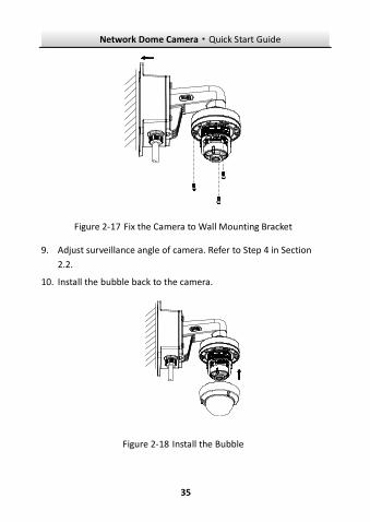
Fix the Camera to Wall Mounting Bracket Figure 2-17
9. Adjust surveillance angle of camera. Refer to Step 4 in Section
2.2.
10. Install the bubble back to the camera.
Install the Bubble Figure 2-18

Network Dome Camera·Quick Start Guide
36
36 Pendant Mounting 2.3.3
The pendant mounting bracket is not included in the package. You
need to prepare one in advance, if you adopt this mounting type.
Steps:
1. Mark the screw holes on desired mounting place.
2. Drill three screw holes for expansion bolts.
3. Route the cables and fix the pendant mounting bracket to
ceiling.
Cables
Figure 2-19 Fix Pendant Mount
4. (Optional) Insert the memory card to the camera, if your camera
supports memory card installation. Refer to Section 2.1.
5. Fix the camera to the cap of the pendant mounting bracket with
3 supplied self-tapping screws.

Network Dome Camera·Quick Start Guide
37
37
Cap
Figure 2-20 Fix the Camera to Cap
6. Screw the cap to the pendant mounting bracket.
Figure 2-21 Install the Cap

Network Dome Camera·Quick Start Guide
38
38 7. Adjust surveillance angle of camera. Refer to Step 4 in Section
2.2.
8. Install the bubble back to the camera.
Incline Mounting 2.3.4
The incline mounting bracket is not included in the package. You
need to prepare one, if you adopt this mounting type.
Steps:
1. Paste the drill template to desired mounting place.
Screw Hole
Ceiling Mounting
Screw Hole
Cable Hole
Drill Template Figure 2-22
2. Drill two screw holes for expansion screws, and a cable hole
according to the template.
3. Fix the incline mounting bracket to ceiling.
Network Dome Camera·Quick Start Guide
39
39
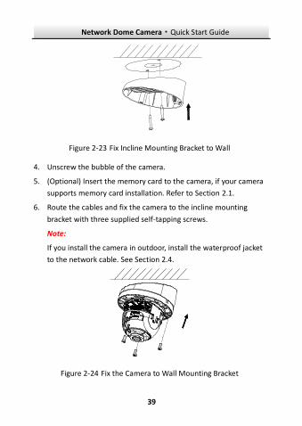
Fix Incline Mounting Bracket to Wall Figure 2-23
4. Unscrew the bubble of the camera.
5. (Optional) Insert the memory card to the camera, if your camera
supports memory card installation. Refer to Section 2.1.
6. Route the cables and fix the camera to the incline mounting
bracket with three supplied self-tapping screws.
Note:
If you install the camera in outdoor, install the waterproof jacket
to the network cable. See Section 2.4.
Fix the Camera to Wall Mounting Bracket Figure 2-24

Network Dome Camera·Quick Start Guide
40
40 7. Adjust surveillance angle of camera. Refer to Step 4 in Section
2.2.
8. Install the bubble back to the camera.
Figure 2-25 Install the Bubble
(Optional) Network Cable Waterproof 2.4Jacket Installation
Purpose:
If the camera is installed outdoor, you can adapt the waterproof
accessory for the network cable after the camera is secured on the
installation surface.
Network Dome Camera·Quick Start Guide
41
41
① ② ③ ④ ⑤ ⑥ ⑦
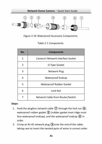
Figure 2-26 Waterproof Accessory Components
Table 2-1 Components
No. Components
1 Camera’s Network Interface Socket
2 O-Type Gasket
3 Network Plug
4 Waterproof Endcap
5 Waterproof Rubber Gasket
6 Lock Nut
7 Network Cable from Router/Switch
Steps:
Feed the plugless network cable ⑦ through the lock nut ⑥, 1.
waterproof rubber gasket ⑤ (rubber gasket inset ridge must
face waterproof endcap), and the waterproof endcap ④ in
order.
Crimp an RJ-45 network plug ③onto the end of the cable, 2.
taking care to insert the twisted pairs of wires in correct order.

Network Dome Camera·Quick Start Guide
42
42 Place the O-type gasket ② onto the end of the camera’s 3.
network interface socket ①.
Insert the network plug ③ into the camera’s network interface 4.
socket ①.
Insert the waterproof rubber gasket ⑤ into the waterproof 5.
endcap ④, and secure lock nut ⑥ with the waterproof
endcap ④.
Align the snap on the waterproof endcap ④ with the notch on 6.
the camera’s network interface socket ①, and then secure the
waterproof endcap ④ to the camera’s network interface
socket ① to finish installation.
Camera
Switch/Router
Align the snap and notch.
i. Insert ⑤ into ④.ii. Secure ⑥ with ④.
Waterproof Accessory Installation Figure 2-27

Network Dome Camera·Quick Start Guide
43
43
3 Set the Network Camera over the LAN
Note:
You shall acknowledge that the use of the product with Internet
access might be under network security risks. For avoidance of any
network attacks and information leakage, please strengthen your
own protection.
If the product does not work properly, contact your dealer or the
nearest service center for help.
Wiring 3.1
Connect the camera to network according to the following figures.
半球
Network Cableor
Network Camera
Computer
Connecting Directly Figure 3-1
网络交换机
半球
Network Cable
Network Cable
or
or
Network Camera Computer
Connecting via a Switch or a Router Figure 3-2

Network Dome Camera·Quick Start Guide
44
44
Activate the Camera 3.2
You are required to activate the camera first by setting a strong
password for it before you can use the camera.
Activation via web browser, activation via SADP, and activation via
client software are all supported. We will take activation via SADP
software and activation via web browser as examples to introduce
the camera activation.
Note:
Refer to the User Manual of Network Camera for Activation via
Client Software.
Activation via Web Browser 3.2.1
Steps:
1. Power on the camera. Connect the camera to your computer or
the switch/router which your computer connects to.
2. Input the IP address into the address bar of the web browser, and
press Enter to enter the activation interface.
Notes:
The default IP address of the camera is 192.168.1.64.
The computer and the camera should belong to the same
subnet.
For the camera enables the DHCP by default, you need to use
the SADP software to search the IP address.
Network Dome Camera·Quick Start Guide
45
45
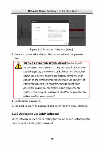
Activation Interface (Web) Figure 3-3
3. Create a password and input the password into the password
field.
STRONG PASSWORD RECOMMENDED– We highly
recommend you create a strong password of your own
choosing (using a minimum of 8 characters, including
upper case letters, lower case letters, numbers, and
special characters) in order to increase the security of
your product. And we recommend you reset your
password regularly, especially in the high security
system, resetting the password monthly or weekly can
better protect your product.
4. Confirm the password.
5. Click OK to save the password and enter the live view interface.
Activation via SADP Software 3.2.2
SADP software is used for detecting the online device, activating the
camera, and resetting the password.
Network Dome Camera·Quick Start Guide
46
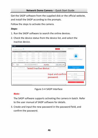
46 Get the SADP software from the supplied disk or the official website,
and install the SADP according to the prompts.
Follow the steps to activate the camera.
Steps:
1. Run the SADP software to search the online devices.
2. Check the device status from the device list, and select the
inactive device.
Select inactive device.
Input and confirm password.
SADP Interface Figure 3-4
Note:
The SADP software supports activating the camera in batch. Refer
to the user manual of SADP software for details.
3. Create and input the new password in the password field, and
confirm the password.
Network Dome Camera·Quick Start Guide
47
47 STRONG PASSWORD RECOMMENDED– We highly
recommend you create a strong password of your own
choosing (using a minimum of 8 characters, including
upper case letters, lower case letters, numbers, and
special characters) in order to increase the security of
your product. And we recommend you reset your
password regularly, especially in the high security
system, resetting the password monthly or weekly can
better protect your product.
Note:
You can enable the Hik-Connect service for the device during
activation. Refer to Chapter 5.1 for detailed information.
4. Click Activate to start activation.
You can check whether the activation is completed on the popup
window. If activation failed, make sure that the password meets
the requirement and try again.
Modify the IP Address 3.3
Purpose:
To view and configure the camera via LAN (Local Area Network), you
need to connect the network camera in the same subnet with your
PC.
Use the SADP software or client software to search and change the
IP address of the device. We take modifying the IP Address via SADP
software as an example to introduce the IP address modification.
For IP address modification via client software, refer to the user
manual of client software.
Network Dome Camera·Quick Start Guide
48
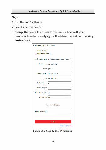
48 Steps:
1. Run the SADP software.
2. Select an active device.
3. Change the device IP address to the same subnet with your
computer by either modifying the IP address manually or checking
Enable DHCP.
Modify the IP Address Figure 3-5
Network Dome Camera·Quick Start Guide
49
49 Note:
You can enable the Hik-Connect service for the device during
activation. Refer to Chapter 5.1 for detailed information.
4. Input the admin password and click Modify to activate your IP
address modification.
The batch IP address modification is supported by the SADP. Refer to
the user manual of SADP for details.
Network Dome Camera·Quick Start Guide
50
50
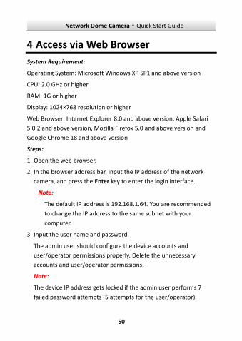
4 Access via Web Browser
System Requirement:
Operating System: Microsoft Windows XP SP1 and above version
CPU: 2.0 GHz or higher
RAM: 1G or higher
Display: 1024×768 resolution or higher
Web Browser: Internet Explorer 8.0 and above version, Apple Safari
5.0.2 and above version, Mozilla Firefox 5.0 and above version and
Google Chrome 18 and above version
Steps:
1. Open the web browser.
2. In the browser address bar, input the IP address of the network
camera, and press the Enter key to enter the login interface.
Note:
The default IP address is 192.168.1.64. You are recommended
to change the IP address to the same subnet with your
computer.
3. Input the user name and password.
The admin user should configure the device accounts and
user/operator permissions properly. Delete the unnecessary
accounts and user/operator permissions.
Note:
The device IP address gets locked if the admin user performs 7
failed password attempts (5 attempts for the user/operator).

Network Dome Camera·Quick Start Guide
51
51 4. Click Login.
Login Interface Figure 4-1
5. Install the plug-in before viewing the live video and managing the
camera. Follow the installation prompts to install the plug-in.
Note:
You may have to close the web browser to finish the installation of
the plug-in.
Download Plug-in Figure 4-2
6. Reopen the web browser after the installation of the plug-in and
repeat steps 2 to 4 to login.
Note:
For detailed instructions of further configuration, please refer to
the user manual of network camera.
Network Dome Camera·Quick Start Guide
52
52
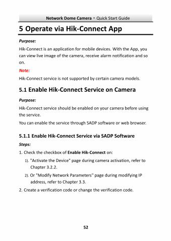
5 Operate via Hik-Connect App
Purpose:
Hik-Connect is an application for mobile devices. With the App, you
can view live image of the camera, receive alarm notification and so
on.
Note:
Hik-Connect service is not supported by certain camera models.
5.1 Enable Hik-Connect Service on Camera
Purpose:
Hik-Connect service should be enabled on your camera before using
the service.
You can enable the service through SADP software or web browser.
Enable Hik-Connect Service via SADP Software 5.1.1
Steps:
1. Check the checkbox of Enable Hik-Connect on:
1). "Activate the Device" page during camera activation, refer to
Chapter 3.2.2.
2). Or "Modify Network Parameters" page during modifying IP
address, refer to Chapter 3.3.
2. Create a verification code or change the verification code.

Network Dome Camera·Quick Start Guide
53
53
Verification Code Setting (SADP) Figure 5-1
Note:
The verification code is required when you add the camera to
Hik-Connect app.
3. Click and read "Terms of Service" and "Privacy Policy".
4. Confirm the settings.
Enable Hik-Connect Service via Web Browser 5.1.2
Before you start:
You need to activate the camera before enabling the service. Refer to
Chapter 3.2.

Network Dome Camera·Quick Start Guide
54
54 Steps:
1. Access the camera via web browser. Refer to Chapter 4.
2. Enter platform access configuration interface: Configuration >
Network > Advanced Settings > Platform Access.
Platform Access Configuration (Web) Figure 5-2
3. Select Platform Access Mode as Hik-Connect.
4. Check Enable.
5. Click and read "Terms of Service" and "Privacy Policy" in pop-up
window.
6. Create a verification code or change the verification code for the
camera.
Note:
The verification code is required when you add the camera to
Hik-Connect app.
7. Save the settings.
Network Dome Camera·Quick Start Guide
55
55
5.2 Hik-Connect Setup
Steps:
1. Download and install the Hik-Connect app by searching
“Hik-Connect” in App Store or Google PlayTM.
2. Launch the app and register for a Hik-Connect user account.
3. Log in Hik-Connect app after registration.
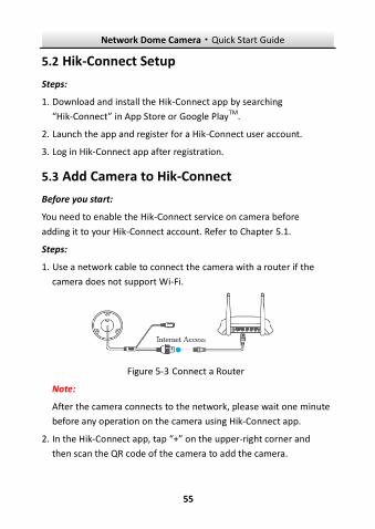
5.3 Add Camera to Hik-Connect
Before you start:
You need to enable the Hik-Connect service on camera before
adding it to your Hik-Connect account. Refer to Chapter 5.1.
Steps:
1. Use a network cable to connect the camera with a router if the
camera does not support Wi-Fi.
Figure 5-3 Connect a Router
Note:
After the camera connects to the network, please wait one minute
before any operation on the camera using Hik-Connect app.
2. In the Hik-Connect app, tap “+” on the upper-right corner and
then scan the QR code of the camera to add the camera.
Network Dome Camera·Quick Start Guide
56
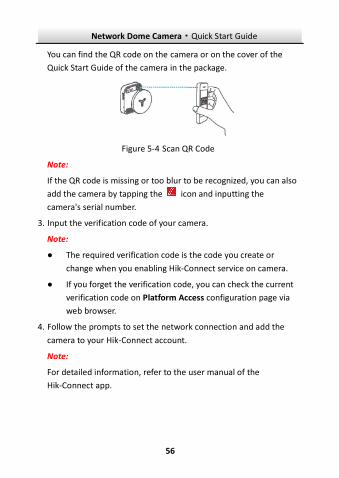
56 You can find the QR code on the camera or on the cover of the
Quick Start Guide of the camera in the package.
Figure 5-4 Scan QR Code
Note:
If the QR code is missing or too blur to be recognized, you can also
add the camera by tapping the icon and inputting the
camera's serial number.
3. Input the verification code of your camera.
Note:
● The required verification code is the code you create or
change when you enabling Hik-Connect service on camera.
● If you forget the verification code, you can check the current
verification code on Platform Access configuration page via
web browser.
4. Follow the prompts to set the network connection and add the
camera to your Hik-Connect account.
Note:
For detailed information, refer to the user manual of the
Hik-Connect app.
Network Dome Camera·Quick Start Guide
57
57
5.4 Initialize the Memory Card
Steps:
Check the memory card status by tapping on the Storage Status in
the Device Settings interface.
If the memory card status displays as Uninitialized, tap to initialize
it. The status will then change to Normal. You can then start
recording any event triggered video in the camera such as motion
detection.

0
UD07705B