Embed Size (px)
Citation preview
2
Outline
> Motivation for Converging L2 Services on MPLS> Network and Service Interworking> Expectations on the New Converged Packet Network> Interworking the User Plane> Interworking the Control Plane> Interworking the Management Plane (OAM)> Conclusions> Further Reading
3
Service Convergence over MPLS
> Service providers are introducing new MPLS based packet switchedcore networks
� They are introducing Ethernet in the access> Motivations:
� Generate new revenues by broadening the range of services delivered from the IP network
� Extend the reach of existing Ethernet/FR/ATM services to new sites� Interconnect regional ATM networks over a national IP/MPLS network� Reduce CAPEX and possibly OPEX� Avoid per-service/per-technology networks
4
Standard Service Convergence Solutions
> Based on Layer 2 Network and Service Interworking functions> Network Interworking:
� Allows networks to communicate transparently across different link layer technologies
� Interworking is performed at the link layer (L2) by encapsulating one link layer in the other
� Typically deployed inside the network and is not visible to end-users> Service Interworking:
� Allows CPEs to exchange service layer PDU across different link layer technologies
� Interworking is performed by terminating the link layers and translating based on knowledge of the payload service context
� Constraints visible to end-users
5
Network and Service Interworking Benefits
ATM
ATMMPLS
Ethernet
Ethernet
Ethernet
ATM PW
Ethernet PW
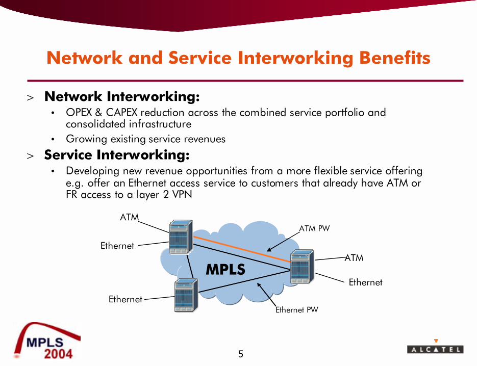
> Network Interworking:� OPEX & CAPEX reduction across the combined service portfolio and
consolidated infrastructure� Growing existing service revenues
> Service Interworking:� Developing new revenue opportunities from a more flexible service offering
e.g. offer an Ethernet access service to customers that already have ATM or FR access to a layer 2 VPN

6
Expectations of the New Converged Packet Network
> Coping with traffic growth in a cost-effective way� Enhance utilization of infrastructure
> Carrier class protection and restoration� Offer flexible levels of protection (e.g., hot-standby versus warm-standby
backup, local versus end-to-end protection)� Provide reactive and pro-active OAM capabilities
> Service level differentiation� Offer different services with different performance objectives (e.g., VoIP,
Virtual Leased Lines, Internet access)� Offer multiple grades of the same service (e.g., VoIP gold, silver)
> Intelligent edge policy decision� Ability to have visibility and to select specific network resources and apply
different policies for routing customer traffic at edge> Maintaining integrity of L2 services
� Transparent carriage of existing L2 services� Seamless interworking with new services at the user, control , and
management (OAM) planes
7
Basics of Pseudo-Wires
MPLSPE /IWF PE /IWF
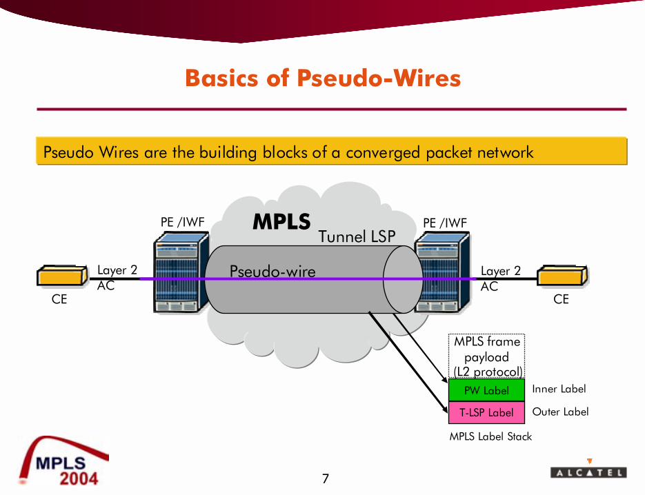
Pseudo Wires are the building blocks of a converged packet network
Layer 2AC
Layer 2AC
CE CE
MPLS framepayload
(L2 protocol)
Tunnel LSP
PW Label Inner Label
T-LSP Label Outer Label
MPLS Label Stack
Pseudo-wire
8
Outline
> Motivation for Converging Services on a Common Packet Network
> Network and Service Interworking> Expectations of the New Converged Packet Network> Interworking the User Plane> Interworking the Control Plane> Interworking the Management Plane (OAM)> Conclusions> Further Reading
9
Some L2 VPN Terminology�
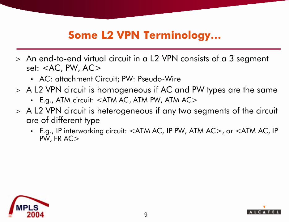
> An end-to-end virtual circuit in a L2 VPN consists of a 3 segment set: <AC, PW, AC>
� AC: attachment Circuit; PW: Pseudo-Wire> A L2 VPN circuit is homogeneous if AC and PW types are the same
� E.g., ATM circuit: <ATM AC, ATM PW, ATM AC>
> A L2 VPN circuit is heterogeneous if any two segments of the circuit are of different type
� E.g., IP interworking circuit: <ATM AC, IP PW, ATM AC>, or <ATM AC, IP PW, FR AC>
10
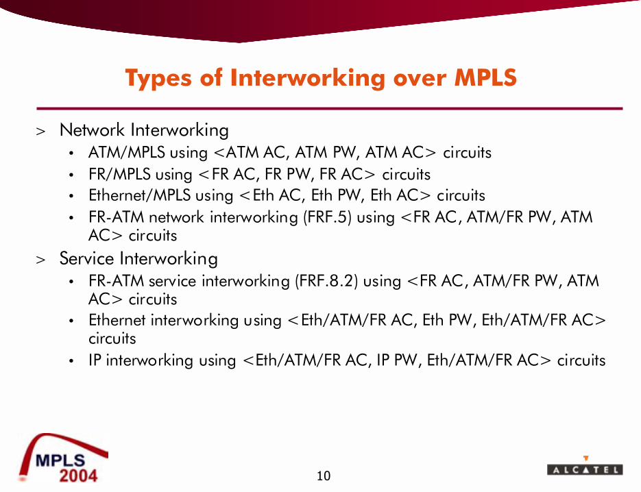
Types of Interworking over MPLS
> Network Interworking� ATM/MPLS using <ATM AC, ATM PW, ATM AC> circuits� FR/MPLS using <FR AC, FR PW, FR AC> circuits� Ethernet/MPLS using <Eth AC, Eth PW, Eth AC> circuits� FR-ATM network interworking (FRF.5) using <FR AC, ATM/FR PW, ATM
AC> circuits> Service Interworking
� FR-ATM service interworking (FRF.8.2) using <FR AC, ATM/FR PW, ATM AC> circuits
� Ethernet interworking using <Eth/ATM/FR AC, Eth PW, Eth/ATM/FR AC> circuits
� IP interworking using <Eth/ATM/FR AC, IP PW, Eth/ATM/FR AC> circuits
11
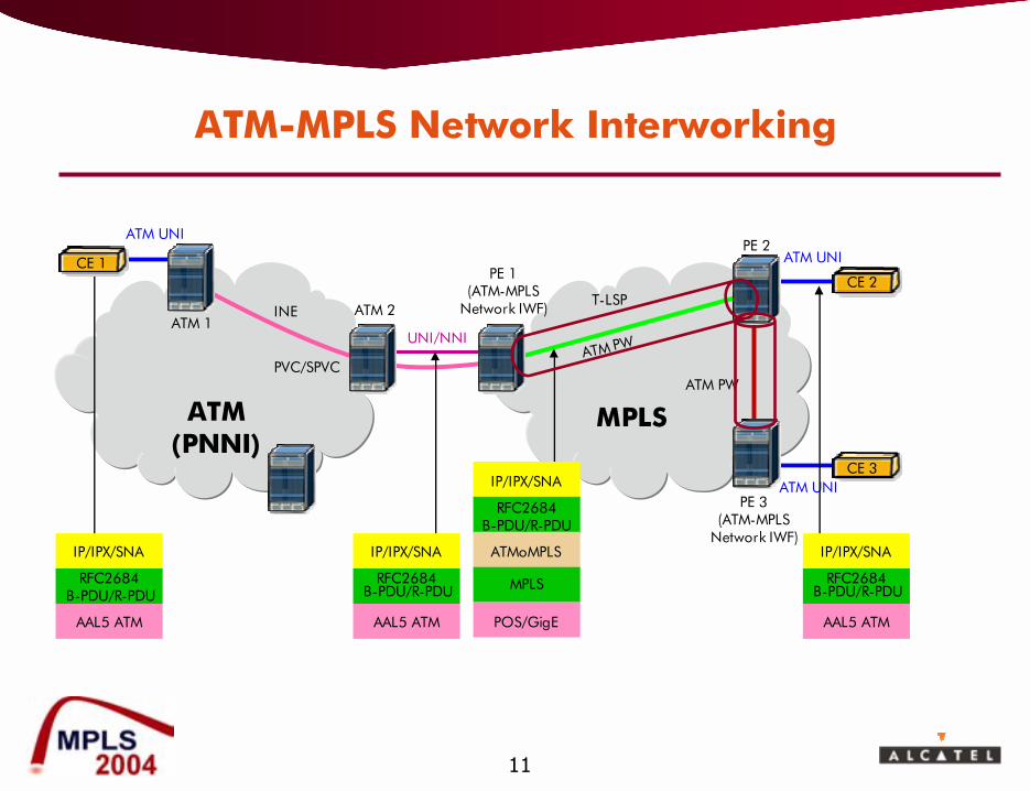
INE
ATM(PNNI)
ATM 2
ATM UNI
ATM UNI
UNI/NNI
T-LSP
PVC/SPVCATM PW
ATM 1
PE 1(ATM-MPLS
Network IWF)
PE 2
MPLS
IP/IPX/SNA
RFC2684B-PDU/R-PDU
AAL5 ATM
PE 3 (ATM-MPLS
Network IWF)
ATM UNI
ATM PW
CE 1
IP/IPX/SNA
RFC2684B-PDU/R-PDU
AAL5 ATM
IP/IPX/SNA
RFC2684B-PDU/R-PDU
ATMoMPLS
MPLS
POS/GigE
CE 2
CE 3
IP/IPX/SNA
RFC2684B-PDU/R-PDU
AAL5 ATM
ATM-MPLS Network Interworking
12
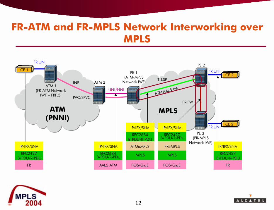
FR-ATM and FR-MPLS Network Interworking over MPLS
INE
ATM(PNNI)
ATM 2
FR UNI
FR UNI
UNI/NNI
T-LSP
PVC/SPVCATM AAL5 PW
ATM 1 (FR-ATM Network
IWF � FRF.5)
PE 1(ATM-MPLS
Network IWF)
PE 2
MPLS
IP/IPX/SNA
RFC2427B-PDU/R-PDU
FR
PE 3 (FR-MPLS
Network IWF)
FR UNI
FR PW
CE 1
IP/IPX/SNA
RFC2684B-PDU/R-PDU
AAL5 ATM
IP/IPX/SNA
RFC2684B-PDU/R-PDU
ATMoMPLS
MPLS
POS/GigE
IP/IPX/SNA
RFC2427B-PDU/R-PDU
FRoMPLS
MPLS
POS/GigE
CE 2
CE 3
IP/IPX/SNA
RFC2427B-PDU/R-PDU
FR
13
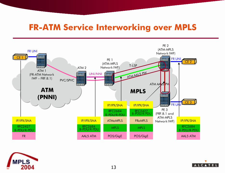
FR-ATM Service Interworking over MPLS
PE 2 (ATM-MPLS
Network IWF)
ATM(PNNI)
ATM 2
FR UNI
FR UNI
UNI/NNI
T-LSP
PVC/SPVCATM AAL5 PW
ATM 1 (FR-ATM Network
IWF � FRF.8.1)
PE 1(ATM-MPLS
Network IWF)
MPLS
IP/IPX/SNA
RFC2427B-PDU/R-PDU
FR
PE 3 (FRF.8.1 and
ATM-MPLS Network IWF)
FR UNI
ATM AAL5 PW
CE 1
IP/IPX/SNA
RFC2684B-PDU/R-PDU
AAL5 ATM
IP/IPX/SNA
RFC2684B-PDU/R-PDU
ATMoMPLS
MPLS
POS/GigE
IP/IPX/SNA
RFC2427B-PDU/R-PDU
FRoMPLS
MPLS
POS/GigE
CE 2
CE 3
IP/IPX/SNA
RFC2684B-PDU/R-PDU
AAL5 ATM
14
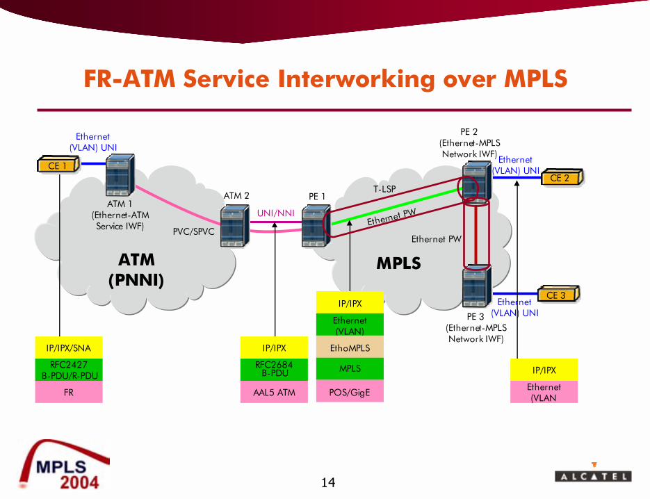
FR-ATM Service Interworking over MPLS
PE 2 (Ethernet-MPLSNetwork IWF)
ATM(PNNI)
ATM 2
UNI/NNI
T-LSP
PVC/SPVCEthernet PW
PE 1
MPLS
IP/IPX/SNA
RFC2427B-PDU/R-PDU
FR
PE 3 (Ethernet-MPLSNetwork IWF)
Ethernet(VLAN) UNI
Ethernet PW
CE 1
IP/IPX
RFC2684B-PDU
AAL5 ATM
IP/IPX
Ethernet(VLAN)
EthoMPLS
MPLS
POS/GigE
CE 2
CE 3
IP/IPX
Ethernet(VLAN
Ethernet(VLAN) UNI
ATM 1 (Ethernet-ATMService IWF)
Ethernet(VLAN) UNI
15
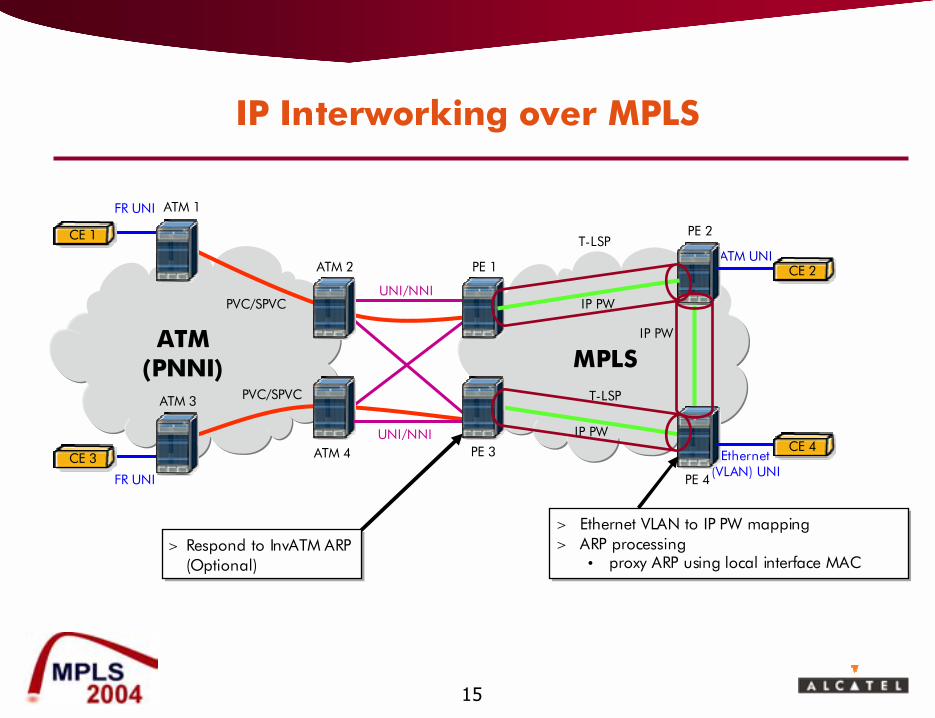
IP Interworking over MPLS
ATM(PNNI) MPLS
ATM 2
ATM 4
FR UNI
Ethernet (VLAN) UNI
UNI/NNI
UNI/NNI
T-LSP
FR UNI
T-LSPPVC/SPVC
PVC/SPVC
ATM 1
ATM 3
PE 4
PE 3
PE 1
PE 2
ATM UNI
IP PW
IP PW
IP PW
CE 1
CE 3
> Respond to InvATM ARP (Optional)
> Respond to InvATM ARP (Optional)
CE 4
CE 2
> Ethernet VLAN to IP PW mapping> ARP processing
� proxy ARP using local interface MAC
> Ethernet VLAN to IP PW mapping> ARP processing
� proxy ARP using local interface MAC
16
End-to-End QoS
> Ingress Classification� MFC, DSCP, 802.1p, L2 I/F context (e.g., ATM Service category & CLP)� <CoS, DP> assigned to packet
> Ingress Policing� Per L2 CoS policing, e.g., Per VPI/VCI/CLP in a ATM AC
> Queuing and Scheduling in PE� Based on assigned <CoS, DP>
> Admission control in PE� Tunnel LSP is assigned bandwidth� PW are CACed against tunnel bandwidth
> Egress remarking in PE� Configurable mapping of <CoS, DP> to EXP
> Queuing and Scheduling in Core LSR� According to the label value and EXP value for a L-LSP� According to the EXP value for a E-LSP
17
AC
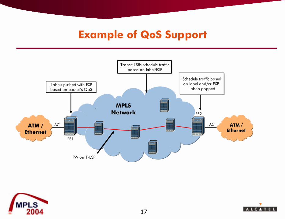
Example of QoS Support
MPLSNetwork
PE1
PE2
ATM / Ethernet
ATM / Ethernet
PW on T-LSP
AC
Labels pushed with EXP based on packet�s QoSLabels pushed with EXP based on packet�s QoS
Schedule traffic based on label and/or EXP.
Labels popped
Schedule traffic based on label and/or EXP.
Labels popped
Transit LSRs schedule traffic based on label/EXP
Transit LSRs schedule traffic based on label/EXP
18
Outline
> Motivation for Converging Services on a Common Packet Network
> Network and Service Interworking> Expectations of the New Converged Packet Network> Interworking the User Plane> Interworking the Control Plane> Interworking the Management Plane (OAM)> Conclusions> Further Reading

19
Connectivity Scenarios Across the MPLS Network
> Scenario 1: � Connectivity of sites attached to the MPLS network
> Scenarios 2 & 3: � Connectivity of sites attached to FR/ATM networks across the
MPLS network
> Scenario 4: � Connectivity of a site attached to a FR/ATM network to a site
attached to the MPLS network
20
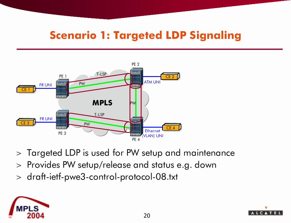
Scenario 1: Targeted LDP Signaling
> Targeted LDP is used for PW setup and maintenance> Provides PW setup/release and status e.g. down> draft-ietf-pwe3-control-protocol-08.txt
MPLS
Ethernet (VLAN) UNI
T-LSP
T-LSP
PW
PW
PE 4
PE 1
PE 2
ATM UNI
PW
FR UNI
FR UNI
CE 1
CE 3
PE 3
CE 2
CE 4
21
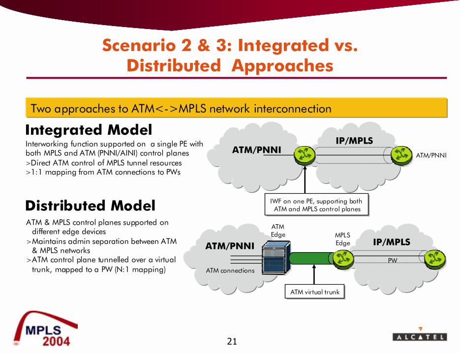
Scenario 2 & 3: Integrated vs. Distributed Approaches
ATM/PNNIIP/MPLS
Integrated Model
ATM/PNNI IP/MPLS
Distributed ModelATMEdge MPLS
Edge
Interworking function supported on a single PE with both MPLS and ATM (PNNI/AINI) control planes>Direct ATM control of MPLS tunnel resources>1:1 mapping from ATM connections to PWs
ATM & MPLS control planes supported on different edge devices
>Maintains admin separation between ATM & MPLS networks
>ATM control plane tunnelled over a virtual trunk, mapped to a PW (N:1 mapping)
ATM/PNNI
ATM connections
PW
Two approaches to ATM<->MPLS network interconnection
IWF on one PE, supporting both ATM and MPLS control planes
IWF on one PE, supporting both ATM and MPLS control planes
ATM virtual trunkATM virtual trunk
22
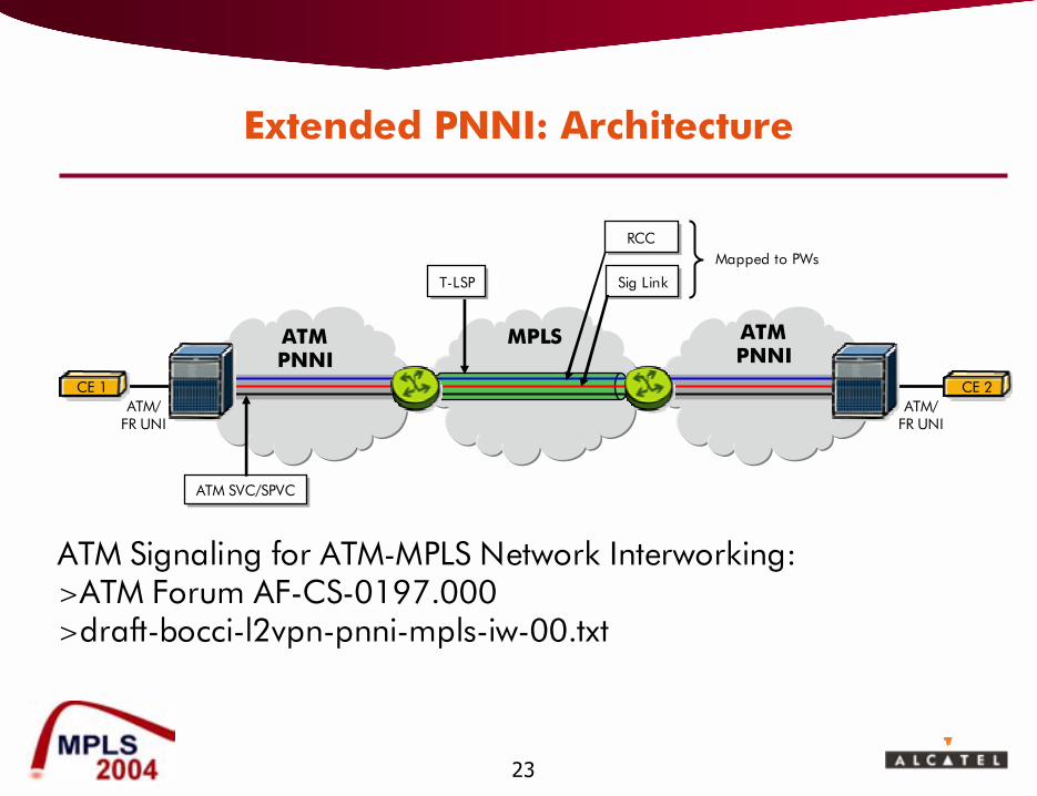
Extended PNNI
> Designed for transparently interconnecting ATM/PNNI networks using SVCs and SPVCs over MPLS core
> ATM/PNNI and MPLS both run on the PE (Integrated model)> Extension to PNNI allows it to allocate PW label on PSN tunnel
� 1:1 mapping between ATM connections and PWs, but can use any PW encapsulation (1:1, N:1, AAL5 SDU, AAL5 PDU)
� PSN tunnel looks like a virtual PNNI port
> Standardised in ATM Forum: AF-CS-0197> Interoperability demonstrated at SuperComm 2004
23
CE 1
ATM PNNI
ATMPNNI
MPLS
CE 2
RCCRCC
Sig LinkSig Link
ATM SVC/SPVCATM SVC/SPVC
Mapped to PWs
ATM/FR UNI
ATM Signaling for ATM-MPLS Network Interworking: >ATM Forum AF-CS-0197.000>draft-bocci-l2vpn-pnni-mpls-iw-00.txt
ATM/FR UNI
T-LSPT-LSP
Extended PNNI: Architecture
24
Properties of Extended PNNI
> Independence between IGP and PNNI routing domains
> Requires PNNI and MPLS on the same PE� No changes to any other switches or LSRs
> Uses any of the standard ATM PW types, but maps 1 ATM connection to 1 PW
� Simple QoS support
� Same OAM model as ATM today
> No impact on MPLS core from high ATM signalling loads
> Full transparency to all ATM switched services and future evolution of PNNI
> PNNI can be used for ATM PW protection / restoration
25
Virtual Trunking
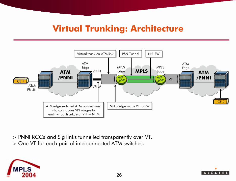
> Range of ATM connections with the same VPI mapped to a virtual trunk at ATM edge
> Virtual trunk is mapped to a N:1 PW at the MPLS edge> Targeted at the distributed model> Virtual trunk is established by provisioning> Two QoS models under discussion:
� Implicit QoS: Each VT is a single QoS class, PW is effectively an L-LSP
� Explicit QoS: Each packet of a given VT can have a different QoStreatment, specified using MPLS EXP bits, PW is effectively an E-LSP
� Requires communication of QoS setting from ATM switch to PE.
26
ATM /PNNI
CE 1
ATM /PNNI
CE 2
ATM/FR UNI
ATMEdge
VPI N
VPI M
MPLS
ATMEdge
VT
MPLSEdge
MPLSEdge
N:1 PWN:1 PWPSN TunnelPSN TunnelVirtual trunk on ATM linkVirtual trunk on ATM link
> PNNI RCCs and Sig links tunnelled transparently over VT.> One VT for each pair of interconnected ATM switches.
ATM edge switched ATM connections into contiguous VPI ranges for
each virtual trunk, e.g. VPI = N..M
ATM edge switched ATM connections into contiguous VPI ranges for
each virtual trunk, e.g. VPI = N..M
MPLS edge maps VT to PWMPLS edge maps VT to PW
Virtual Trunking: Architecture
27
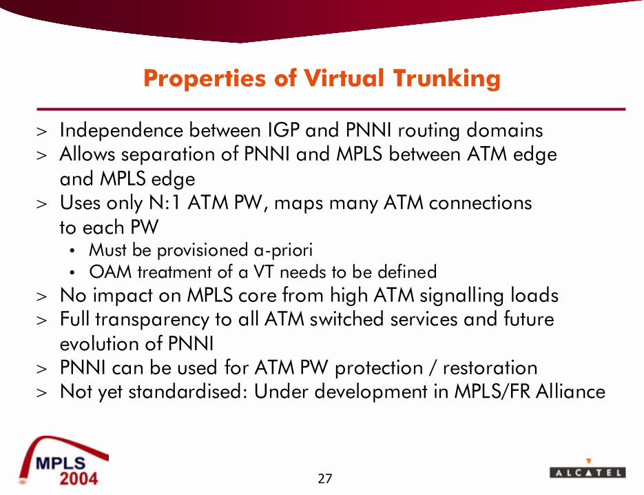
Properties of Virtual Trunking
> Independence between IGP and PNNI routing domains> Allows separation of PNNI and MPLS between ATM edge
and MPLS edge> Uses only N:1 ATM PW, maps many ATM connections
to each PW� Must be provisioned a-priori� OAM treatment of a VT needs to be defined
> No impact on MPLS core from high ATM signalling loads> Full transparency to all ATM switched services and future
evolution of PNNI> PNNI can be used for ATM PW protection / restoration> Not yet standardised: Under development in MPLS/FR Alliance
28
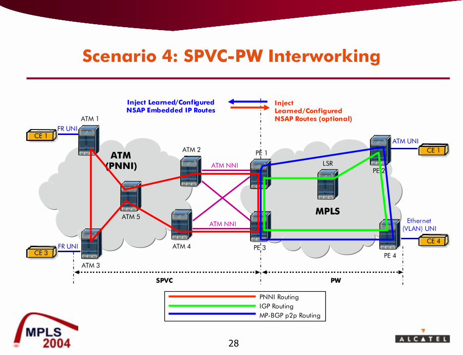
Scenario 4: SPVC-PW Interworking
PE 4
ATM(PNNI)
ATM 1
ATM 3
ATM 2
ATM 4
FR UNI
ATM UNI
ATM 5
PNNI RoutingIGP RoutingMP-BGP p2p Routing
Inject Learned/Configured NSAP Routes (optional)
Inject Learned/Configured NSAP Embedded IP Routes
Ethernet (VLAN) UNI
SPVC PW
ATM NNI
ATM NNI
CE 1
FR UNICE 3
CE 4
PE 1
MPLS
PE 3
LSR
CE 1
PE 2
29
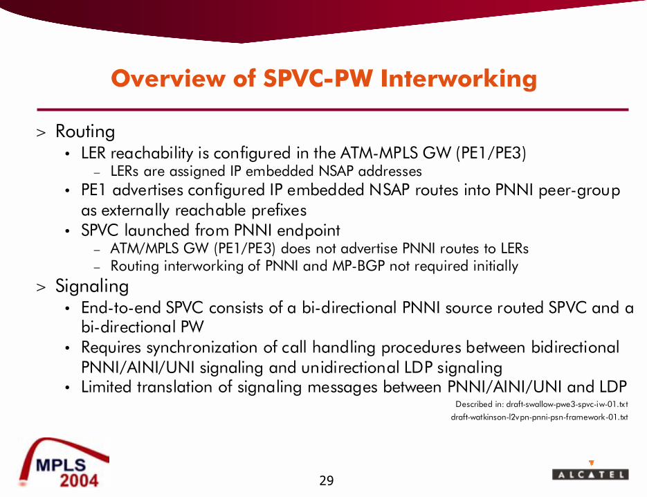
Overview of SPVC-PW Interworking
> Routing� LER reachability is configured in the ATM-MPLS GW (PE1/PE3)
� LERs are assigned IP embedded NSAP addresses� PE1 advertises configured IP embedded NSAP routes into PNNI peer-group
as externally reachable prefixes� SPVC launched from PNNI endpoint
� ATM/MPLS GW (PE1/PE3) does not advertise PNNI routes to LERs� Routing interworking of PNNI and MP-BGP not required initially
> Signaling� End-to-end SPVC consists of a bi-directional PNNI source routed SPVC and a
bi-directional PW� Requires synchronization of call handling procedures between bidirectional
PNNI/AINI/UNI signaling and unidirectional LDP signaling� Limited translation of signaling messages between PNNI/AINI/UNI and LDP
Described in: draft-swallow-pwe3-spvc-iw-01.tx t
draft-watkinson-l2vpn-pnni-psn-framework-01.txt
30
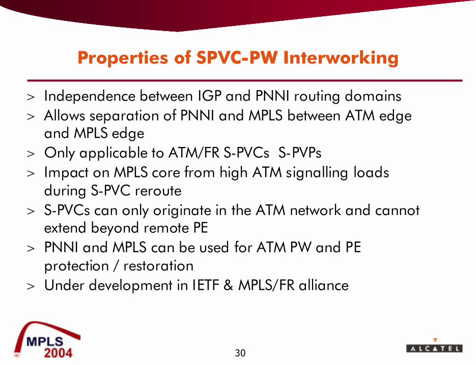
Properties of SPVC-PW Interworking
> Independence between IGP and PNNI routing domains> Allows separation of PNNI and MPLS between ATM edge
and MPLS edge> Only applicable to ATM/FR S-PVCs S-PVPs> Impact on MPLS core from high ATM signalling loads
during S-PVC reroute> S-PVCs can only originate in the ATM network and cannot
extend beyond remote PE> PNNI and MPLS can be used for ATM PW and PE
protection / restoration> Under development in IETF & MPLS/FR alliance

31
Outline
> Motivation for Converging Services on a Common Packet Network
> Network and Service Interworking> Expectations of the New Converged Packet Network> Interworking the User Plane> Interworking the Control Plane> Interworking the Management Plane (OAM)> Conclusions> Further Reading
32
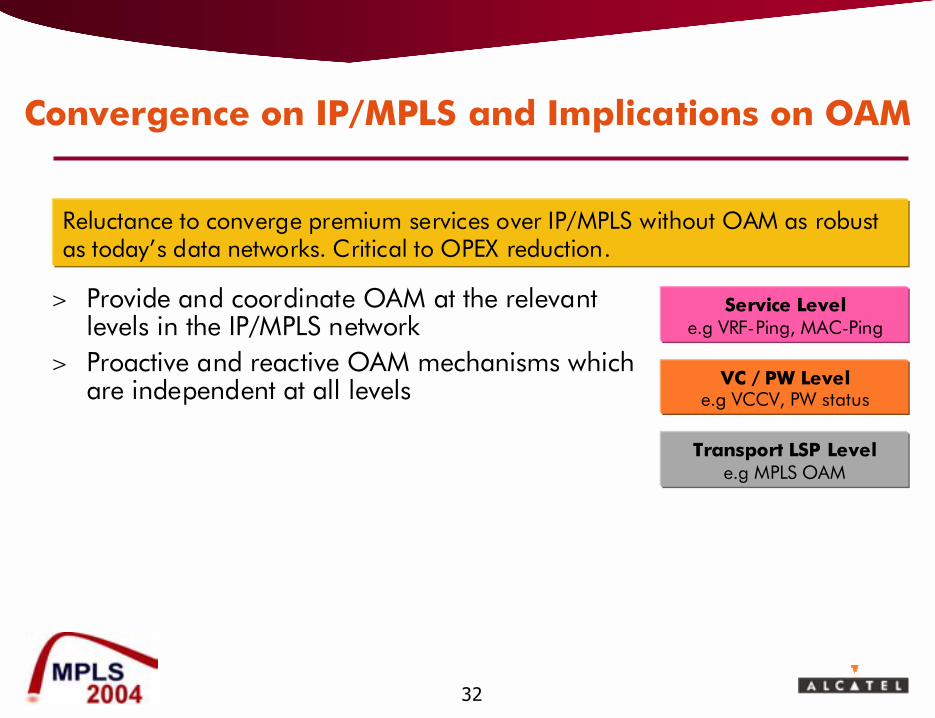
Convergence on IP/MPLS and Implications on OAM
> Provide and coordinate OAM at the relevant levels in the IP/MPLS network
> Proactive and reactive OAM mechanisms which are independent at all levels
Service Levele.g VRF-Ping, MAC-Ping
VC / PW Levele.g VCCV, PW status
Transport LSP Levele.g MPLS OAM
Reluctance to converge premium services over IP/MPLS without OAM as robust as today�s data networks. Critical to OPEX reduction.
33
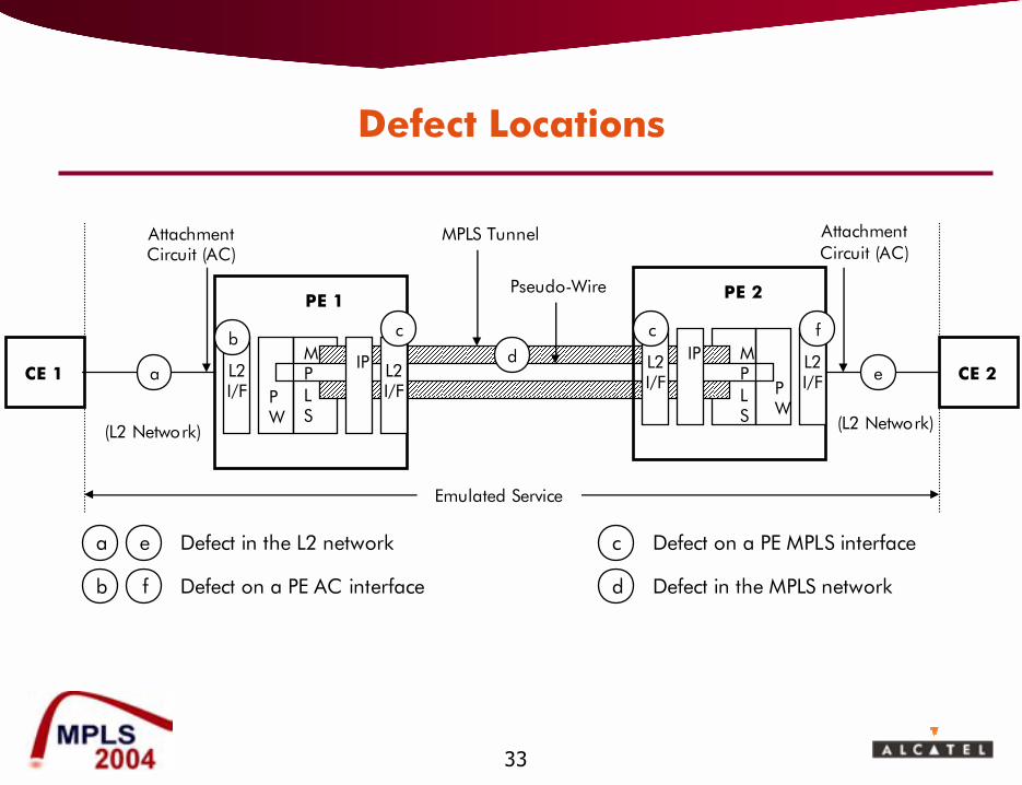
Defect Locations
AttachmentCircuit (AC)
AttachmentCircuit (AC)
Emulated Service
Pseudo-Wire
MPLS Tunnel
CE 2CE 1 a
(L2 Network) (L2 Network)
ed
a e
b f
c
d
Defect in the L2 network
Defect on a PE AC interface
Defect on a PE MPLS interface
Defect in the MPLS network
PE 1
PW
IP L2 I/F
L2 I/F
bMPLS
c
PE 2
PW
IP L2 I/F
L2 I/F
cMPLS
f
34
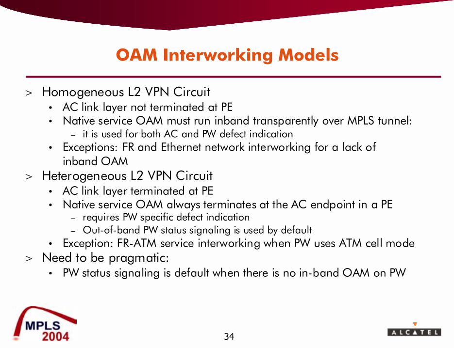
OAM Interworking Models
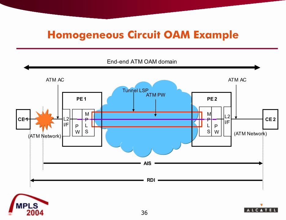
> Homogeneous L2 VPN Circuit� AC link layer not terminated at PE� Native service OAM must run inband transparently over MPLS tunnel:
� it is used for both AC and PW defect indication� Exceptions: FR and Ethernet network interworking for a lack of
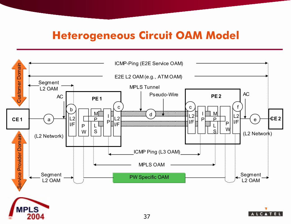
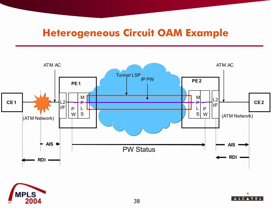
inband OAM> Heterogeneous L2 VPN Circuit
� AC link layer terminated at PE� Native service OAM always terminates at the AC endpoint in a PE
� requires PW specific defect indication� Out-of-band PW status signaling is used by default
� Exception: FR-ATM service interworking when PW uses ATM cell mode> Need to be pragmatic:
� PW status signaling is default when there is no in-band OAM on PW
35
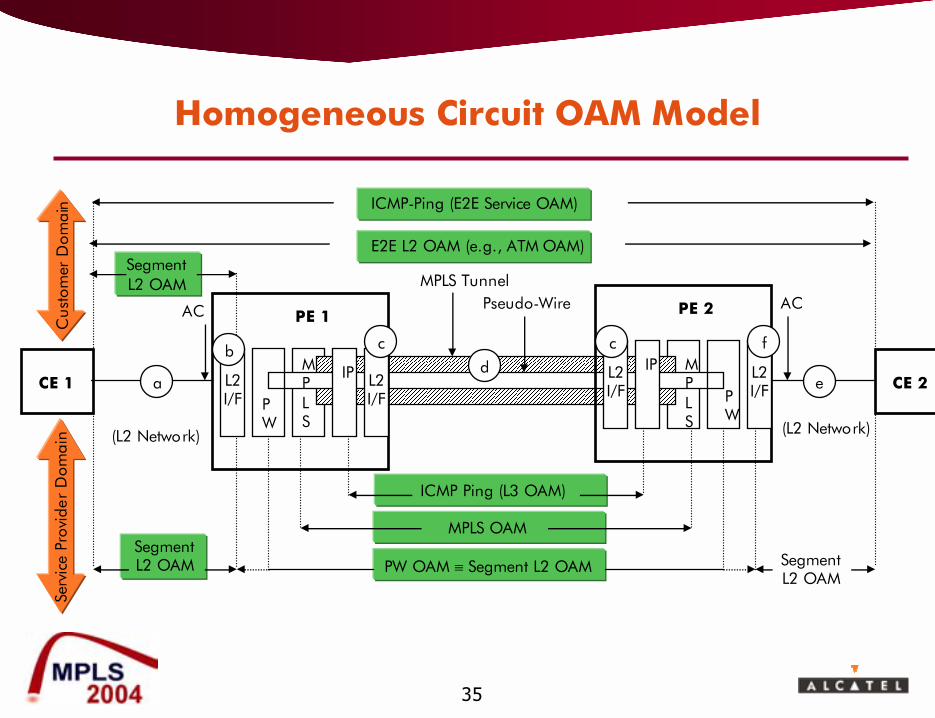
Homogeneous Circuit OAM Model
MPLS OAM
PW OAM ≡ Segment L2 OAM
Serv
ice
Prov
ider
Dom
ain
ICMP-Ping (E2E Service OAM)
E2E L2 OAM (e.g., ATM OAM)Segment L2 OAM
AC ACPseudo-WireMPLS Tunnel
CE 2CE 1 a
(L2 Network) (L2 Network)
ed
PE 1
PW
IP L2 I/F
L2 I/F
bMPLS
c
PE 2
PW
IP L2 I/F
L2 I/F
cMPLS
f
ICMP Ping (L3 OAM)
Segment L2 OAM Segment
L2 OAM
Cus
tom
er D
omai
n
36
Homogeneous Circuit OAM Example
AIS
RDI
ATM AC ATM AC
ATM PWTunnel LSP
CE 2CE 1 a
(ATM Network) (ATM Network)
PE 1
PW
L2 I/F
PE 2
PW
L2 I/F
MPLS
MPLS
End-end ATM OAM domain
37
Heterogeneous Circuit OAM Model
MPLS OAM
PW Specific OAM
Serv
ice
Prov
ider
Dom
ain
ICMP-Ping (E2E Service OAM)
E2E L2 OAM (e.g., ATM OAM)Segment L2 OAM
AC ACPseudo-WireMPLS Tunnel
CE 2CE 1 a
(L2 Network) (L2 Network)
ed
PE 1
PW
IP L2
I/FL2 I/F
bMPLS
c
PE 2
PW
IP L2
I/FL2 I/F
cMPLS
f
ICMP Ping (L3 OAM)
Segment L2 OAM
Segment L2 OAM
Cus
tom
er D
omai
n
38
Heterogeneous Circuit OAM Example
AIS
RDI
ATM AC ATM AC
IP PWTunnel LSP
CE 2CE 1 a
(ATM Network) (ATM Network)
PE 1
PW
L2 I/F
PE 2
PW
L2 I/F
MPLS
MPLS
AIS
RDIPW Status
39
Outline
> Motivation for Converging Services on a Common Packet Network
> Expectations of the New Converged Packet Network> Network and Service Interworking> Interworking the User Plane> Interworking the Control Plane> Interworking the Management Plane (OAM)> Conclusions> Further Reading
40
> Many carriers are looking at MPLS for Service Convergence� Offering or extending the reach of revenue generating Layer 2 services
over an MPLS backbone� Converging layer 2 services to leverage the same backbone to provide
enhanced revenue generating Layer 3 services
> Two approaches to support layer 2 services over MPLS� Layer 2 Network Interworking & Service Interworking� Will require comprehensive interworking at user, control and
management planes to realise potential benefits
Conclusions

41
References*
> Network and Service User Plane Interworking� ATM PW: draft-ietf-pwe3-atm-encap-06.txt� Frame Relay PW: draft-ietf-pwe3-frame-relay-03.txt� Ethernet PW: draft-ietf-pwe3-ethernet-encap-07.txt� IP interworking PW: draft-shah-l2vpn-arp-mediation-01.txt, draft-balus-pwe3-ip-pseudowire-
01.txt� ATM-MPLS network interworking: ATM Forum af-aic-0178.001� ATM-MPLS network interworking: ITU-T Y.1411, Y.1412� FR-ATM network interworking: Frame Relay Forum FRF.5� FR-ATM service interworking: Frame Relay Forum FRF.8.2� FRF.8.2 over MPLS: MPLS FR Alliance work in progress� Ethernet interworking over MPLS: MPLS FR Alliance work in progress
> Control Plane Interworking� PW signaling: draft-ietf-pwe3-control-protocol-08.txt� ATM Signaling for ATM-MPLS Network Interworking (Extended PNNI):
� ATM Forum AF-CS-0197.000� draft-bocci-l2vpn-pnni-mpls-iw-01.txt
� ATM-PWE3 signaling interworking: � draft-swallow-pwe3-spvc-iw-01.txt� draft-watkinson-l2vpn-pnni-psn-framework-01.txt
42
References* (II)
> ATM OAM� ITU-T I.610 Recommendation
> FR OAM� PVC Management (LMI): ITU-T Q.933 Annex A� OAM: Frame Relay Forum FRF.19
> MPLS OAM� LSP-Ping and Trace-Route: draft-ietf-mpls-lsp-ping-04.txt� MPLS OAM requirements: draft-ietf-mpls-oam-requirements-02.txt� MPLS OAM framework: draft-allan-mpls-oam-frmwk-05.txt� MPLS OAM: ITU-T Y.1711
> L2 VPN and Pseudo-Wire (PW) OAM� draft-ietf-l2vpn-vpls-ldp-04.txt� draft-aissaoui-l2vpn-vpws-iw-oam-01.txt� draft-ietf-pwe3-vccv-01.txt� draft-ietf-pwe3-oam-msg-map-00.txt� draft-ietf-pwe3-atm-encap-04.txt� ITU-T Y.1413