Embed Size (px)
Citation preview
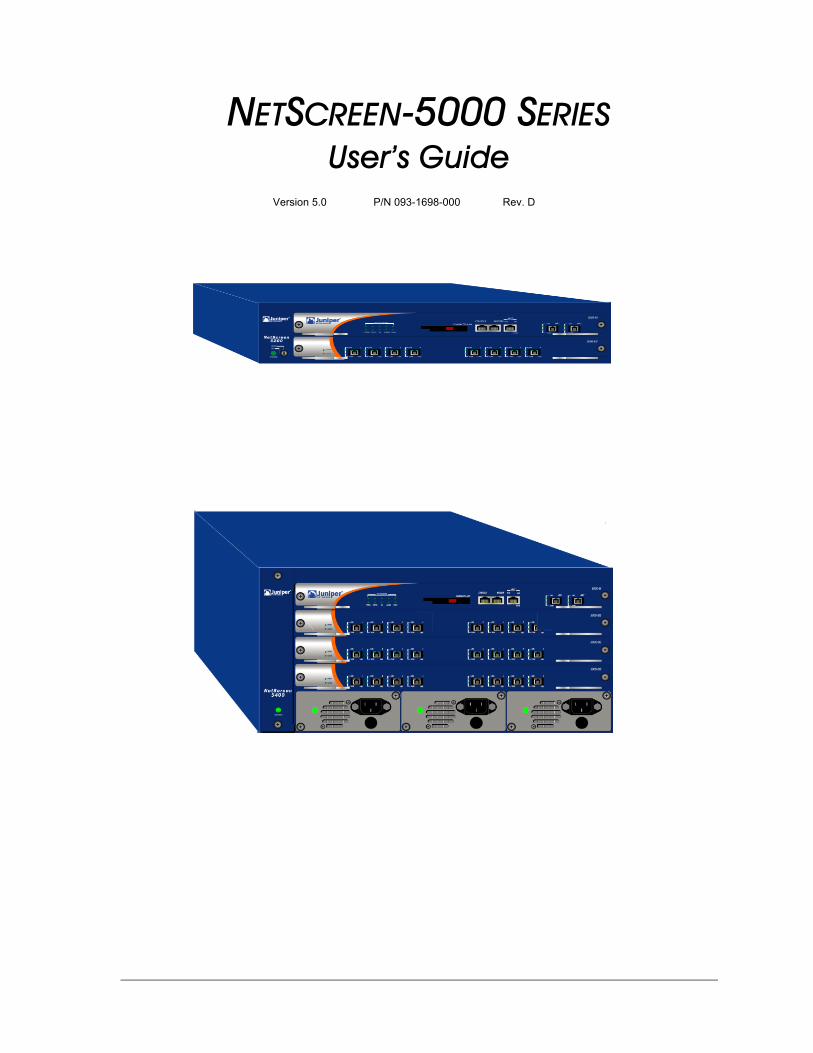
NETSCREEN-5000 SERIESUser’s Guide
Version 5.0 P/N 093-1698-000 Rev. D
Copyright NoticeCopyright © 2006 Juniper Networks, Inc. All rights reserved.Juniper Networks, the Juniper Networks logo, NetScreen, NetScreen Technologies, GigaScreen, and the NetScreen logo are registered trademarks of Juniper Networks, Inc. NetScreen-5GT, NetScreen-5XP, NetScreen-5XT, NetScreen-25, NetScreen-50, NetScreen-100, NetScreen-204, NetScreen-208, NetScreen-500, NetScreen-5200, NetScreen-5400, NetScreen-Global PRO, NetScreen-Global PRO Express, NetScreen-Remote Security Client, NetScreen-Remote VPN Client, NetScreen-IDP 10, NetScreen-IDP 100, NetScreen-IDP 500, GigaScreen ASIC, GigaScreen-II ASIC, and NetScreen ScreenOS are trademarks of Juniper Networks, Inc. All other trademarks and registered trademarks are the property of their respective companies.Information in this document is subject to change without notice.No part of this document may be reproduced or transmitted in any form or by any means, electronic or mechanical, for any purpose, without receiving written permission from: Juniper Networks, Inc.ATTN: General Counsel1194 N. Mathilda Ave.Sunnyvale, CA 94089-1206
FCC StatementThe following information is for FCC compliance of Class A devices: This equipment has been tested and found to comply with the limits for a Class A digital device, pursuant to part 15 of the FCC rules. These limits are designed to provide reasonable protection against harmful interference when the equipment is operated in a commercial environment. The equipment generates, uses, and can radiate radio-frequency energy and, if not installed and used in accordance with the instruction manual, may cause harmful interference to radio communications. Operation of this equipment in a residential area is likely to cause harmful interference, in which case users will be required to correct the interference at their own expense.If this equipment does cause harmful interference to radio or television reception, which can be determined by turning the equipment off and on, the user is encouraged to try to correct the interference by one or more of the following measures:
• Reorient or relocate the receiving antenna.• Increase the separation between the equipment and receiver.• Consult the dealer or an experienced radio/TV technician for help.• Connect the equipment to an outlet on a circuit different from that to which the receiver is connected.
Caution: Changes or modifications to this product could void the user's warranty and authority to operate this device.
DisclaimerTHE SOFTWARE LICENSE AND LIMITED WARRANTY FOR THE ACCOMPANYING PRODUCT ARE SET FORTH IN THE INFORMATION PACKET THAT SHIPPED WITH THE PRODUCT AND ARE INCORPORATED HEREIN BY THIS REFERENCE. IF YOU ARE UNABLE TO LOCATE THE SOFTWARE LICENSE OR LIMITED WARRANTY, CONTACT YOUR NETSCREEN REPRESENTATIVE FOR A COPY.
Table of ContentsPreface...................................................................................................................vii
Guide Organization ................................................................................... vii
Command Line Interface (CLI) Conventions ............................................. viii
Juniper Networks NetScreen Publications ................................................. viii
Chapter 1 Overview ...............................................................................................1
NetScreen-5000 Series ................................................................................ 2NetScreen-5200 .............................................................................................. 2NetScreen-5400 .............................................................................................. 2
Power Supplies ............................................................................................ 3NetScreen-5200 Power Recommendations..................................................... 3NetScreen-5400 Power Recommendations..................................................... 3The DC Power Supply ...................................................................................... 4The AC Power Supply....................................................................................... 4
Fan Modules ............................................................................................... 5
NetScreen-5000 Modules ........................................................................... 5Management Modules.................................................................................... 6
The 5000-M Management Module .............................................................6The 5000-M2 Management Module ...........................................................7
Secure Port Modules........................................................................................ 8The 5000-8G SPM ........................................................................................8The 5000-2G24FE SPM ................................................................................9The 5000-8G2 SPM ....................................................................................10The 5000-2XGE SPM ..................................................................................11
Chapter 2 Installing the Device ............................................................................13
General Installation Guidelines ................................................................ 14
Equipment Rack Installation Guidelines ................................................... 14
Mounting the NetScreen-5000 Series ....................................................... 15NetScreen-5200 Front and Rear Mount......................................................... 15NetScreen-5200 Mid-Mount .......................................................................... 16NetScreen-5400 Front Mount......................................................................... 16
Installing and Connecting the AC Power Supply ...................................... 17
Installing and Wiring a DC Power Supply .................................................. 17
Establishing an HA Connection ................................................................. 19
Connecting the NetScreen-5000 Series to a Router or Switch .................. 19
Chapter 3 Configuring the Device .......................................................................21
Operational Modes .................................................................................. 22Transparent Mode ......................................................................................... 22Route Mode................................................................................................... 22
The NetScreen-5000 Interfaces ................................................................ 23NetScreen-5200 Interfaces............................................................................ 23
NetScreen-5000 Series iii
Table of Contents
NetScreen-5400 Interfaces............................................................................ 24Configurable Interfaces ................................................................................ 24
Performing Initial Connection and Configuration ..................................... 25Establishing a Terminal Emulator Connection................................................ 25Upgrading the Firmware During the Boot Process ......................................... 26Changing Your Admin Name and Password ................................................. 27Setting Port and Interface IP Addresses ......................................................... 27
Viewing Current Interface Settings ............................................................27Setting the IP Address of the Management Interface ...............................27Setting the IP Address for the Trust Zone Interface .....................................28Setting the IP Address for the Untrust Zone Interface .................................28Allowing Outbound Traffic .........................................................................29
Configuring the Device for Telnet and WebUI Sessions ............................. 29Starting a Console Session Using Telnet ......................................................... 29Starting a Console Session Using Dialup........................................................ 30Establishing a GUI Management Session....................................................... 30
Configuring the Chassis Alarm .................................................................. 31
Configuring Jumbo Frames ...................................................................... 32
Configuring Aggregate Interfaces ............................................................ 32
Using CLI Commands to Reset the Device ................................................ 33
Chapter 4 Servicing the Device............................................................................35
Removing and Reseating Modules ........................................................... 36
Replacing a DC Power Supply .................................................................. 36
Replacing an AC Power Supply ................................................................ 37
Replacing the Fan Module ....................................................................... 37NetScreen-5200 Fan Module ........................................................................ 38NetScreen-5200 Fan Tray Filter ...................................................................... 39NetScreen-5400 Fan Module ........................................................................ 40NetScreen-5400 Fan Tray Filter ...................................................................... 42
Connecting and Disconnecting Gigabit Ethernet Cables ........................ 43
Removing and Installing a Mini-GBIC Transceiver ..................................... 43
Appendix A Specifications ....................................................................................A-I
NetScreen-5200 Attributes ....................................................................... A-II
NetScreen-5400 Attributes ....................................................................... A-II
Electrical Specification ............................................................................ A-II
Environmental .......................................................................................... A-II
NEBS Certifications .................................................................................. A-III
Safety Certifications ................................................................................ A-III
iv User’s Guide

EMI Certifications .....................................................................................A-III
Connectors ..............................................................................................A-III
Appendix B Port Descriptions and LED Status........................................................ B-I
Module Port Descriptions ..........................................................................B-II
Module LED Descriptions ......................................................................... B-III
Status LED States ......................................................................................B-IVInterpreting Status LEDs for the Management Modules ...............................B-IVInterpreting Status LEDs for the Secure Port Module ......................................B-VInterpreting Ethernet Port Status LEDs for All Modules ....................................B-V
Power Supply LEDs ...................................................................................B-VIInterpreting Power Supply LED Status for the NetScreen-5200 .....................B-VIInterpreting Power Supply LED Status for the NetScreen-5400 .....................B-VI
Single SPM Installed ................................................................................B-VI
Fan LED ...................................................................................................B-VII
Index .................................................................................................................... IX-I
NetScreen-5000 Series v

Table of Contents
vi User’s Guide
PrefaceThe Juniper Networks NetScreen-5000 Series consists of purpose-built, high-performance security systems that provide IPSec VPN and firewall services for large-scale carrier, enterprise, and data-center networks. Built around NetScreen’s third-generation ASIC technology and distributed system architecture, the NetScreen-5000 Series offers excellent scalability and flexibility.
The NetScreen-5000 Series includes the following device models:• The NetScreen-5200, a chassis-based, two-slot network security device.• The NetScreen-5400, a chassis-based, four-slot network security device.
NetScreen-5000 Series architecture features multiple processing modules. These include a management module that provides overall system control, and security processing modules that allow a variety of port configurations. Together, these modules provide a wide range of performance and security gateway configurations. Because the modules can work in many combinations, you can customize the NetScreen-5000 Series to accommodate the specific requirements of your organization.
The NetScreen-5000 Series also employs a switch fabric for data exchange and a separate multi-bus channel for control information, thus delivering scalable performance for the most demanding environments.
GUIDE ORGANIZATIONThis manual has four chapters and two appendices:
Chapter 1, Overview provides a detailed overview of the system, its modules, Fast Ethernet (FE) and mini-GBIC connectors, power supplies, and fan tray.
Chapter 2, Installing the Device details how to rack mount the NetScreen-5000 Series, connect the power supplies, and connect the modules to the network in addition to providing desktop site requirements and guidelines for rack mounting.
Chapter 3, Configuring the Device details how to obtain an IP address for an interface on one of the modules and how to aggregate ports on one of the modules.
Chapter 4, Servicing the Device provides procedures on how to replace your module and power supplies.
Appendix A, Specifications provides a list of physical specifications about theNetScreen-5000 Series, the modules, and power supplies.
Appendix B, Port Descriptions and LED Status provides descriptions of port and LED behavior.
NetScreen-5000 Series vii
Preface
COMMAND LINE INTERFACE (CLI) CONVENTIONSThe following conventions are used when presenting the syntax of a command line interface (CLI) command:
• Anything inside square brackets [ ] is optional.• Anything inside braces { } is required.• If there is more than one choice, each choice is separated by a pipe ( | ). For
example,set interface { ether1/1 | ether1/2 | ether2/2 } manage
means “set the management options for the ether1/1, ether1/2, or ether2/2 interface”.
• Variables appear in italic. For example:set admin user name1 password xyz
When a CLI command appears within the context of a sentence, it is in bold (except for variables, which are always in italic). For example: “Use the get system command to display the serial number of a NetScreen device.”
JUNIPER NETWORKS NETSCREEN PUBLICATIONSTo obtain technical documentation for any Juniper Networks NetScreen product, visit www.juniper.net/techpubs/.
For technical support, open a support case using the Case Manager link at http://www.juniper.net/support/ or call 1-888-314-JTAC (within the United States) or 1-408-745-9500 (outside the United States).
If you find any errors or omissions in the following content, please contact us at the e-mail address below:
Note: When typing a keyword, you only have to type enough letters to identify the word uniquely. For example, typing set adm u joe j12fmt54 is enough to enter the command set admin user joe j12fmt54. Although you can use this shortcut when entering commands, all the commands documented here are presented in their entirety.
viii User’s Guide
1Chapter 1
OverviewThis chapter provides detailed descriptions of the NetScreen-5000 Series, modules, power supplies, and fan assemblies.
Topics explained in this chapter include:• “NetScreen-5000 Series” on page 2
– “NetScreen-5200” on page 2– “NetScreen-5400” on page 2
• “Power Supplies” on page 3– “NetScreen-5200 Power Recommendations” on page 3– “NetScreen-5400 Power Recommendations” on page 3– “The DC Power Supply” on page 4– “The AC Power Supply” on page 4
• “Fan Modules” on page 5• “NetScreen-5000 Modules” on page 5
– “Management Modules” on page 6– “Secure Port Modules” on page 8
NetScreen-5000 Series 1
Chapter 1 Overview
NETSCREEN-5000 SERIESThis section describes the NetScreen-5000 Series, which currently includes the NetScreen-5200 and the NetScreen-5400.
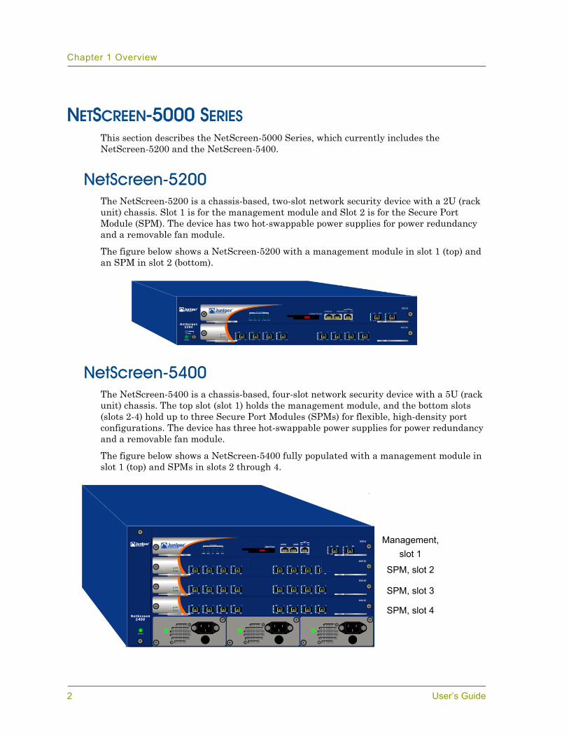
NetScreen-5200The NetScreen-5200 is a chassis-based, two-slot network security device with a 2U (rack unit) chassis. Slot 1 is for the management module and Slot 2 is for the Secure Port Module (SPM). The device has two hot-swappable power supplies for power redundancy and a removable fan module.
The figure below shows a NetScreen-5200 with a management module in slot 1 (top) and an SPM in slot 2 (bottom).
NetScreen-5400The NetScreen-5400 is a chassis-based, four-slot network security device with a 5U (rack unit) chassis. The top slot (slot 1) holds the management module, and the bottom slots (slots 2-4) hold up to three Secure Port Modules (SPMs) for flexible, high-density port configurations. The device has three hot-swappable power supplies for power redundancy and a removable fan module.
The figure below shows a NetScreen-5400 fully populated with a management module in slot 1 (top) and SPMs in slots 2 through 4.
SPM, slot 2
SPM, slot 3
SPM, slot 4
Management,slot 1
2 User’s Guide
Power Supplies
POWER SUPPLIESThe NetScreen-5000 Series can use two kinds of power supplies:
• Direct Current (DC) Power Supply• Alternating Current (AC) Power Supply
The slots for these power supplies are located in the back of the NetScreen-5200 and on the front of the NetScreen-5400.
When two or more power supplies are in service, they share the power load equally. The power supplies are hot-swappable, so you can remove one and replace it without affecting device operation. Each power supply is intended to receive power from separate feeds.
When one power supply fails, the other(s) automatically assume the full load and the device logs a system alarm. This alarm is viewable through the WebUI or a console accessing the NetScreen Command Line Interface (CLI). The Alarm LED on the management module glows red in response to any power supply failure.
NetScreen-5200 Power RecommendationsAlthough the NetScreen-5200 can run with one power supply, it is advisable to install both. This practice minimizes the likelihood of system failure due to individual power supply failure.
When either power supply fails, the Alarm LED on the management module glows red. If both are operational, then the Alarm LED is off. For more information on power supply LEDs, see Appendix B, Port Descriptions and LED Status.
NetScreen-5400 Power RecommendationsWhen the NetScreen-5400 contains only two modules, it can operate with one power supply. However, if the system contains three or four modules, the system requires at least two power supplies. In either case, it is advisable to install all three power supplies. This practice minimizes the likelihood of system failure due to individual power supply failure.
When any power supply fails, the Alarm LED on the management module glows red. While all three are operational, the Alarm LED is off. For more information on power supply LEDs, see Appendix B, Port Descriptions and LED Status.
Note: You can order a NetScreen-5000 Series that runs on DC power. For DC-powered units, the power supply has a DC terminal block with three sockets.
Warning: You must replace the failed power supply as soon as possible; otherwise, system damage can occur. See “Servicing the Device” on page 35 for instructions on how to replace a power supply.
NetScreen-5000 Series 3

Chapter 1 Overview
The DC Power SupplyThe DC power supply weighs about three pounds. The faceplate contains a power LED, a power switch, a cooling fan vent, and three DC power terminal blocks that connect to power cables.
The figure below shows the NetScreen-5200 DC power supply.
The AC Power SupplyThe AC power supply weighs about three pounds. The faceplate contains a power LED, a power switch, a male power outlet, and a cooling fan vent.
The figure below shows the NetScreen-5200 AC power supply.
Thumbscrew
Power LED
DC PowerTerminal Blocks
Power Switch
Grounding Screw
Fuse
Power LED
Power Switch
Male Power Outlet
Thumbscrew
4 User’s Guide
Fan Modules
FAN MODULESThe NetScreen-5200 has a three-fan module and the NetScreen-5400 has a two-fan module. You can access the fan module from the left front side of each chassis.
• To remove the NetScreen-5200 fan module, turn the fan knob in the unlock position, then gently pull the fan module lever toward you to slide the module out.
• To remove the NetScreen-5400 fan module, loosen the two thumb screws that secure the fan module, then gently slide the module out.
If a fan stops operating due to failure or removal, then the system continues to run and generates an alarm. When you replace the fan, do not leave the fan tray empty for more than two minutes. See “Replacing the Fan Module” on page 37 for more information.
NETSCREEN-5000 MODULESThe NetScreen-5000 Series systems support two module types:
• NetScreen-5000 management modules• NetScreen-5000 Secure Port Modules (SPMs)
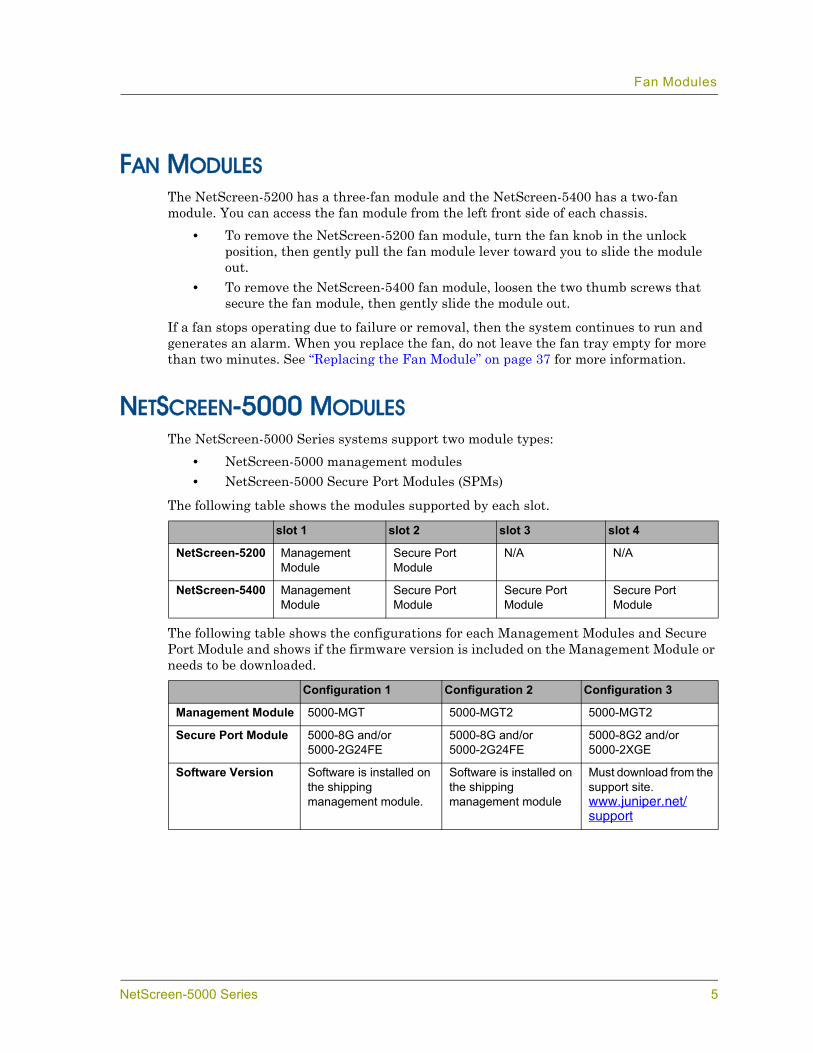
The following table shows the modules supported by each slot.
The following table shows the configurations for each Management Modules and Secure Port Module and shows if the firmware version is included on the Management Module or needs to be downloaded.
slot 1 slot 2 slot 3 slot 4
NetScreen-5200 Management Module
Secure Port Module
N/A N/A
NetScreen-5400 Management Module
Secure Port Module
Secure Port Module
Secure Port Module
Configuration 1 Configuration 2 Configuration 3
Management Module 5000-MGT 5000-MGT2 5000-MGT2
Secure Port Module 5000-8G and/or 5000-2G24FE
5000-8G and/or 5000-2G24FE
5000-8G2 and/or 5000-2XGE
Software Version Software is installed on the shipping management module.
Software is installed on the shipping management module
Must download from the support site. www.juniper.net/support
NetScreen-5000 Series 5

Chapter 1 Overview
Management ModulesThe management module provides general-purpose CPU delivery, and contains dedicated High Availability (HA) and management interfaces. It handles tasks such as management access, session setup and termination, and Internet Key Exchange (IKE) negotiation. There are currently two management modules: The 5000-M and 5000-M2.
The 5000-M Management ModuleThe 5000-M management module is based around a powerful, 600-MHz PowerPC CPU, which assists other system elements, primarily with non-flow related tasks. The 5000-M management module provides overall management and control of the system. Although it performs system management, the primary function of the 5000-M is to support the other modules.
Features of the 5000-M management module include:• A management port, for WebUI management or Command Line Interface
sessions.• An RJ-45 console port, for connecting serial terminal emulation programs such
as HyperTerminal.• Two High Availability (HA) ports.• A modem port.
The 5000-M management module also has port Link and Activity LEDs, CPU utilization indicators, a High Availability (HA) LED, an Alarm LED, a Status LED, a Flash LED, and a Power LED. In addition, it has a compact flash slot for flash memory card installation.
Power LED
Status LED
HA LED
Alarm LED
Flash LED
Compact Flash Slot
Console Port
Modem Port
Management Port High Availability PortsCPU Utilization
LEDs
6 User’s Guide
NetScreen-5000 Modules
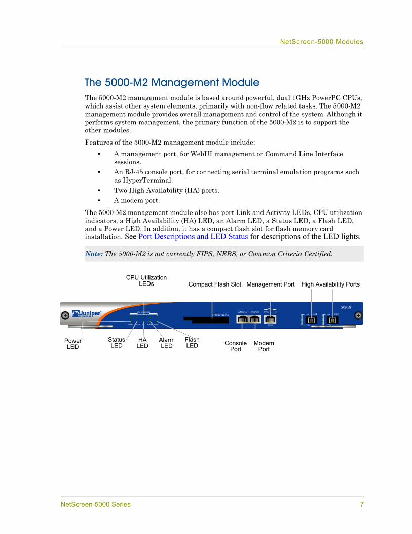
The 5000-M2 Management ModuleThe 5000-M2 management module is based around powerful, dual 1GHz PowerPC CPUs, which assist other system elements, primarily with non-flow related tasks. The 5000-M2 management module provides overall management and control of the system. Although it performs system management, the primary function of the 5000-M2 is to support the other modules.
Features of the 5000-M2 management module include:• A management port, for WebUI management or Command Line Interface
sessions.• An RJ-45 console port, for connecting serial terminal emulation programs such
as HyperTerminal.• Two High Availability (HA) ports.• A modem port.
The 5000-M2 management module also has port Link and Activity LEDs, CPU utilization indicators, a High Availability (HA) LED, an Alarm LED, a Status LED, a Flash LED, and a Power LED. In addition, it has a compact flash slot for flash memory card installation. See Port Descriptions and LED Status for descriptions of the LED lights.
Note: The 5000-M2 is not currently FIPS, NEBS, or Common Criteria Certified.
Power LED
Status LED
HA LED
Alarm LED
Flash LED
Compact Flash Slot
Console Port
Modem Port
Management Port High Availability PortsCPU Utilization
LEDs
NetScreen-5000 Series 7
Chapter 1 Overview
Secure Port ModulesSecure Port Modules (SPMs) perform general packet processing and device connection tasks for devices that communicate with the NetScreen-5000 Series. These modules are based around the GigaScreen-II ASIC.
SPMs handle packets as they enter and exit the system, providing packet parsing, classification, and flow-level processing. SPMs also provide encryption, decryption, Network Address Translation (NAT), and session lookup features. When packets require processing beyond that provided by an SPM, the NetScreen-5000 Series hands them off to the management module for further processing.
There are currently four SPM models:• The 5000-8G SPM provides eight 1-Gigabit Small Form Factor Pluggable (SFP)
mini-Gigabit Interface Converter (GBIC) Ethernet ports. This SPM is supplied with SX gigabit fiber transceivers.
• The 5000-2G24FE SPM provides two mini-GBIC Gigabit Ethernet ports and 24 10/100 Ethernet ports. This SPM is supplied with two SX gigabit fiber transceivers.
• The 5000-8G2 SPM provides eight 1-Gigabit mini-GBIC Ethernet ports. This SPM is supplied with SX gigabit fiber transceivers.
• The 5000-2XGE SPM provides two 10-Gigabit Form Factor Pluggable (XFP) mini-GBIC Ethernet ports. The transceivers for this SPM must be purchased separately.
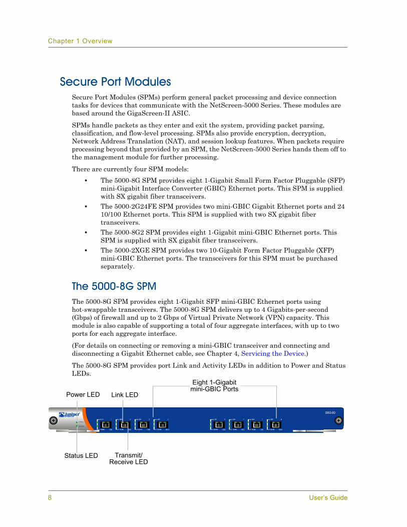
The 5000-8G SPMThe 5000-8G SPM provides eight 1-Gigabit SFP mini-GBIC Ethernet ports using hot-swappable transceivers. The 5000-8G SPM delivers up to 4 Gigabits-per-second (Gbps) of firewall and up to 2 Gbps of Virtual Private Network (VPN) capacity. This module is also capable of supporting a total of four aggregate interfaces, with up to two ports for each aggregate interface.
(For details on connecting or removing a mini-GBIC transceiver and connecting and disconnecting a Gigabit Ethernet cable, see Chapter 4, Servicing the Device.)
The 5000-8G SPM provides port Link and Activity LEDs in addition to Power and Status LEDs.
Power LED
Status LED
Link LED
Transmit/Receive LED
Eight 1-Gigabit mini-GBIC Ports
8 User’s Guide
NetScreen-5000 Modules
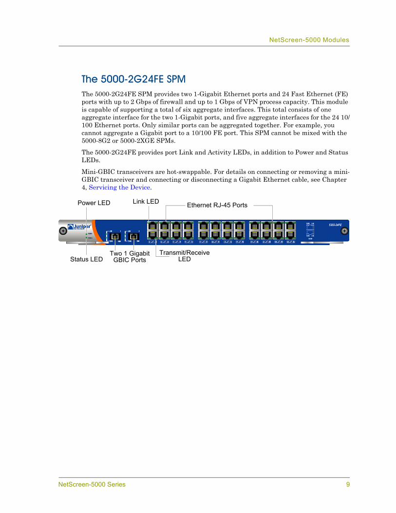
The 5000-2G24FE SPMThe 5000-2G24FE SPM provides two 1-Gigabit Ethernet ports and 24 Fast Ethernet (FE) ports with up to 2 Gbps of firewall and up to 1 Gbps of VPN process capacity. This module is capable of supporting a total of six aggregate interfaces. This total consists of one aggregate interface for the two 1-Gigabit ports, and five aggregate interfaces for the 24 10/100 Ethernet ports. Only similar ports can be aggregated together. For example, you cannot aggregate a Gigabit port to a 10/100 FE port. This SPM cannot be mixed with the 5000-8G2 or 5000-2XGE SPMs.
The 5000-2G24FE provides port Link and Activity LEDs, in addition to Power and Status LEDs.
Mini-GBIC transceivers are hot-swappable. For details on connecting or removing a mini-GBIC transceiver and connecting or disconnecting a Gigabit Ethernet cable, see Chapter 4, Servicing the Device.
Link LED
Status LEDTwo 1 Gigabit GBIC Ports
Transmit/Receive LED
Power LED Ethernet RJ-45 Ports
NetScreen-5000 Series 9
Chapter 1 Overview
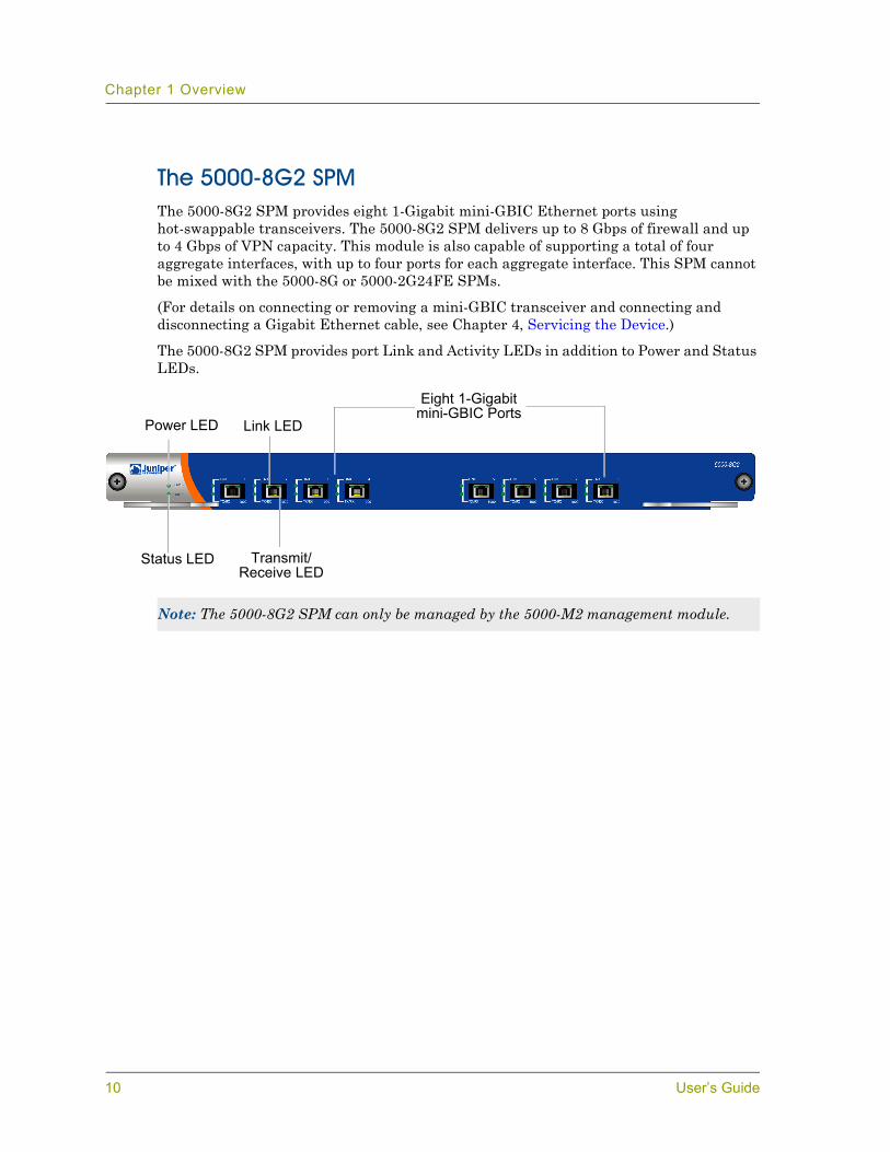
The 5000-8G2 SPMThe 5000-8G2 SPM provides eight 1-Gigabit mini-GBIC Ethernet ports using hot-swappable transceivers. The 5000-8G2 SPM delivers up to 8 Gbps of firewall and up to 4 Gbps of VPN capacity. This module is also capable of supporting a total of four aggregate interfaces, with up to four ports for each aggregate interface. This SPM cannot be mixed with the 5000-8G or 5000-2G24FE SPMs.
(For details on connecting or removing a mini-GBIC transceiver and connecting and disconnecting a Gigabit Ethernet cable, see Chapter 4, Servicing the Device.)
The 5000-8G2 SPM provides port Link and Activity LEDs in addition to Power and Status LEDs.
Note: The 5000-8G2 SPM can only be managed by the 5000-M2 management module.
Power LED
Status LED
Link LED
Transmit/Receive LED
Eight 1-Gigabit mini-GBIC Ports
10 User’s Guide
NetScreen-5000 Modules
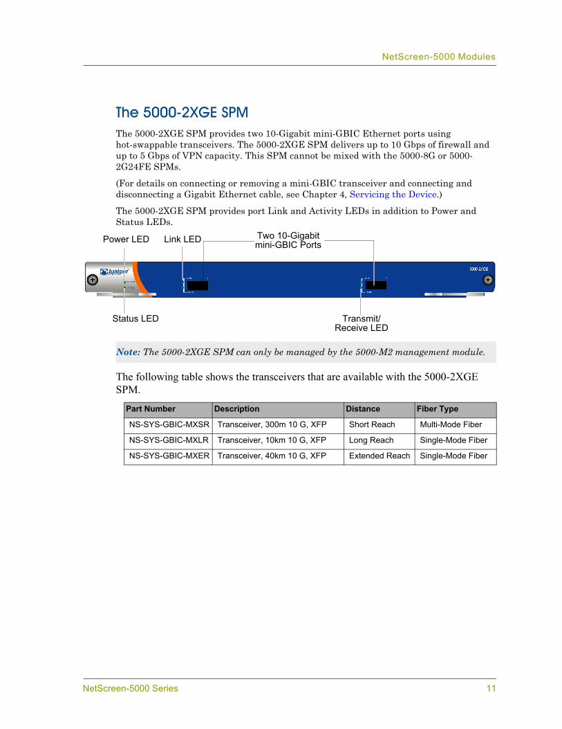
The 5000-2XGE SPMThe 5000-2XGE SPM provides two 10-Gigabit mini-GBIC Ethernet ports using hot-swappable transceivers. The 5000-2XGE SPM delivers up to 10 Gbps of firewall and up to 5 Gbps of VPN capacity. This SPM cannot be mixed with the 5000-8G or 5000-2G24FE SPMs.
(For details on connecting or removing a mini-GBIC transceiver and connecting and disconnecting a Gigabit Ethernet cable, see Chapter 4, Servicing the Device.)
The 5000-2XGE SPM provides port Link and Activity LEDs in addition to Power and Status LEDs.
The following table shows the transceivers that are available with the 5000-2XGE SPM.
Note: The 5000-2XGE SPM can only be managed by the 5000-M2 management module.
Part Number Description Distance Fiber Type
NS-SYS-GBIC-MXSR Transceiver, 300m 10 G, XFP Short Reach Multi-Mode Fiber
NS-SYS-GBIC-MXLR Transceiver, 10km 10 G, XFP Long Reach Single-Mode Fiber
NS-SYS-GBIC-MXER Transceiver, 40km 10 G, XFP Extended Reach Single-Mode Fiber
Power LED
Status LED Transmit/Receive LED
Link LED Two 10-Gigabit mini-GBIC Ports
NetScreen-5000 Series 11

Chapter 1 Overview
12 User’s Guide

2Chapter 2
Installing the DeviceThis chapter describes how to install a NetScreen-5000 Series in an equipment rack or on a desktop and how to configure the device on a network. Topics in this chapter include:
• “General Installation Guidelines” on page 14• “Equipment Rack Installation Guidelines” on page 14• “Mounting the NetScreen-5000 Series” on page 15
– “NetScreen-5200 Front and Rear Mount” on page 15– “NetScreen-5200 Mid-Mount” on page 16– “NetScreen-5400 Front Mount” on page 16
• “Installing and Connecting the AC Power Supply” on page 17• “Installing and Wiring a DC Power Supply” on page 17• “Establishing an HA Connection” on page 19• “Connecting the NetScreen-5000 Series to a Router or Switch” on page 19
NetScreen-5000 Series 13
Chapter 2 Installing the Device
GENERAL INSTALLATION GUIDELINESObserving the following precautions can prevent injuries, equipment failures, and shutdowns:
• Never assume that the power supply is disconnected from a power source. Always check first.
• Room temperature might not be sufficient to keep equipment at acceptable temperatures without an additional circulation system. Ensure that the room in which you operate the NetScreen-5000 Series has adequate air circulation.
• Do not work alone if potentially hazardous conditions exist.• Look carefully for possible hazards in your work area, such as moist floors,
ungrounded power extension cables, frayed power cords, and missing safety grounds.
EQUIPMENT RACK INSTALLATION GUIDELINESThe location of the chassis and the layout of your equipment rack or wiring room are crucial for proper system operation.
Use the following guidelines while configuring your equipment rack:• Enclosed racks must have adequate ventilation. An enclosed rack should have
louvered sides and a fan to provide cooling air.• When mounting a chassis in an open rack, ensure that the rack frame does not
block the intake or exhaust ports. If you install the chassis on slides, then check the position of the chassis when it is seated all the way into the rack.
• In an enclosed rack with a ventilation fan in the top, equipment higher in the rack can draw heat from the lower devices. Always provide adequate ventilation for equipment at the bottom of the rack.
• Baffles can isolate exhaust air from intake air. The best placement of the baffles depends on the airflow patterns in the rack.
You can mount the device in a standard 19-inch equipment rack. Rack mounting requires the following tools:
• 1 Phillips-head screwdriver• Rack-compatible screws • The included rear slide kit (for the rear and front mount method) on the
NetScreen-5200• Front-mount brackets
Important: Although you can place the NetScreen-5000 Series on a desktop for operation, NetScreen does not recommend deploying it in this manner.
Important: To prevent abuse and intrusion by unauthorized personnel, it is extremely important to install the NetScreen device in a locked-room environment.
14 User’s Guide
Mounting the NetScreen-5000 Series
There are two ways to rack mount the NetScreen-5200:• Rear and front mount• Mid-mount
You can only front-mount the NetScreen-5400.
MOUNTING THE NETSCREEN-5000 SERIESThe following sections describe how to rack mount the NetScreen-5000 Series.
• NetScreen-5200 Front and Rear Mount• NetScreen-5200 Mid-Mount• NetScreen-5400 Front Mount
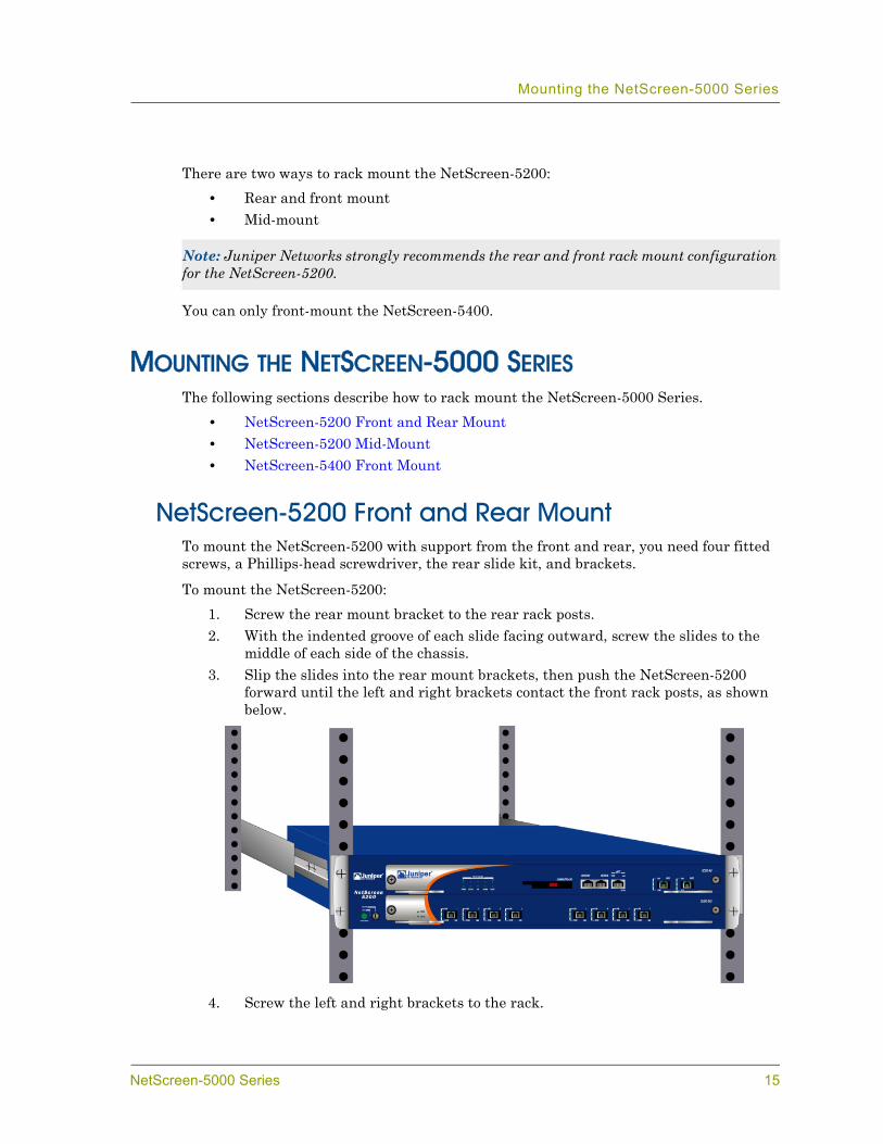
NetScreen-5200 Front and Rear MountTo mount the NetScreen-5200 with support from the front and rear, you need four fitted screws, a Phillips-head screwdriver, the rear slide kit, and brackets.
To mount the NetScreen-5200:1. Screw the rear mount bracket to the rear rack posts.2. With the indented groove of each slide facing outward, screw the slides to the
middle of each side of the chassis.3. Slip the slides into the rear mount brackets, then push the NetScreen-5200
forward until the left and right brackets contact the front rack posts, as shown below.
4. Screw the left and right brackets to the rack.
Note: Juniper Networks strongly recommends the rear and front rack mount configuration for the NetScreen-5200.
NetScreen-5000 Series 15
Chapter 2 Installing the Device
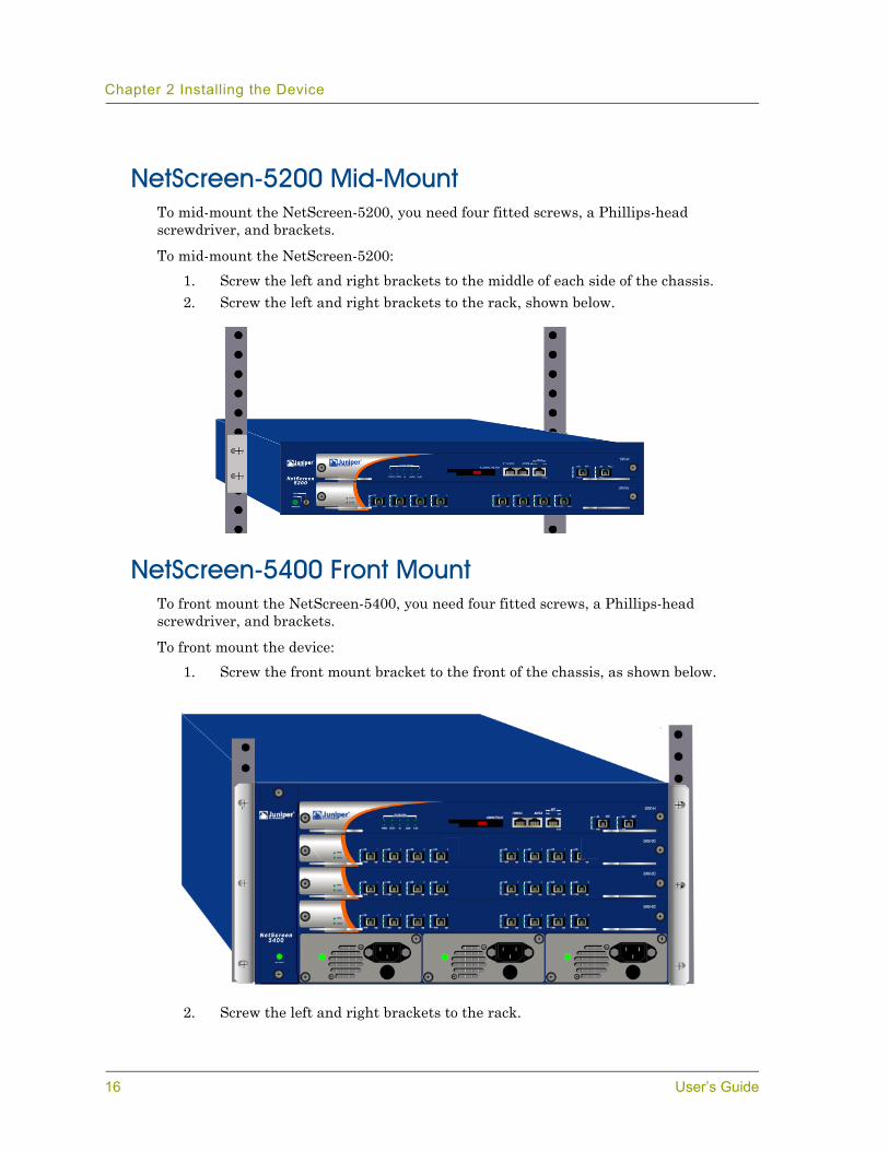
NetScreen-5200 Mid-MountTo mid-mount the NetScreen-5200, you need four fitted screws, a Phillips-head screwdriver, and brackets.
To mid-mount the NetScreen-5200:1. Screw the left and right brackets to the middle of each side of the chassis.2. Screw the left and right brackets to the rack, shown below.
NetScreen-5400 Front MountTo front mount the NetScreen-5400, you need four fitted screws, a Phillips-head screwdriver, and brackets.
To front mount the device:1. Screw the front mount bracket to the front of the chassis, as shown below.
2. Screw the left and right brackets to the rack.
16 User’s Guide

Installing and Connecting the AC Power Supply
INSTALLING AND CONNECTING THE AC POWER SUPPLYTo install and connect the AC power supply to the NetScreen-5000 Series:
1. On the NetScreen-5200, slide the power supply into one of the power compartments in the back of the system.
On the NetScreen-5400, slide the power supply into one of the power compartments on the front of the system.
2. Fasten the power supply to the system by tightening the corner screws into the eyelets on the sides of the power supply.
3. If you want to install two power supplies in the NetScreen-5200 or three power supplies in the NetScreen-5400, then repeat steps 1 and 2 for the remaining power supplies.
4. Connect the female end of a standard power cord to the male connector on the back of each power supply.
5. Connect each power cord to a standard 100-240-Volt power outlet.
6. Turn the power switches on.
INSTALLING AND WIRING A DC POWER SUPPLYTo install and connect the DC power supply to the NetScreen-5000 Series system:
1. On the NetScreen-5200, slide the power supply into one of the power compartments in the back of the system.
On the NetScreen-5400, slide the power supply into one of the power compartments on the front of the system.
2. Fasten the power supply to the system by tightening the corner screws into the eyelets on the sides of the power supply.
3. If you want to install two power supplies in the NetScreen-5200 or three power supplies in the NetScreen-5400, then repeat steps 1 and 2 for the remaining power supplies.
Note: Whenever you deploy two or more power supplies to a NetScreen-5000 Series system, connect each to a different power source. Each power supply is intended to receive power from separate feeds.
Note: If there are multiple power supplies in the NetScreen-5000 Series system and any of them are off, then the Alarm LED on the management module glows red. This alarm indicates that maximum system stability requires all installed power supplies to be operational.
NetScreen-5000 Series 17

Chapter 2 Installing the Device
The DC power supply, power switch, grounding screw, and terminal blocks, are located on the faceplate of the power supply unit.
To connect the DC power supply to a grounding point at your site:1. Remove the hex nut on the grounding screw.2. Place the ground lug on the screw and tighten the hex nut securely.3. Connect the other end of the grounding lug wire to a grounding point at your
site.
To connect DC power feeds to the terminal blocks:1. Loosen the retaining screws on each terminal block.2. Insert the 0V DC (positive voltage) return wire into the center COM connector
and the -48V DC power feed wire into either the left or right connector.3. Fasten the screws over the connectors.4. Turn the power switches on.
Warning: You must shut off the electric current to the DC feed wires before connecting the wires to the power supplies. Also, make sure that the power switch is in the off position.
Note: If there are multiple power supplies in the NetScreen-5000 Series system and any of them are off, then the Alarm LED on the Management Module glows red. This alarm indicates that maximum system stability requires all installed power supplies to be operational.
Thumbscrew
Power LED
DC PowerTerminal Block
Power Switch
GroundingScrew
-48V -48VCOM
18 User’s Guide
Establishing an HA Connection
ESTABLISHING AN HA CONNECTIONTo assure continuous traffic flow in the event of a system failure, you can cable and configure two NetScreen devices in a redundant cluster, with one device acting as a master and the other as its backup. The master propagates all its network, configuration and session information to the backup. Should the master fail, the backup is promoted to master and takes over the traffic processing.
To physically connect the master and backup devices, the 5000-M and 5000-M2 management modules provide a pair of High Availability (HA) ports. To connect the NetScreen-5000 Series systems, you can use the provided Gigabit Ethernet mini-GBIC cable. Use this cable to connect the HA1 port on one system to the HA1 port on another system. Though you cannot connect HA ports between 5000-M and 5000-M2 management modules, you can connect HA ports between the same type of management module. For example, a 5000-M management module to another 5000-M management module.
For information on setting up HA configurations, see the NetScreen Concepts & Examples ScreenOS Reference Guide.
CONNECTING THE NETSCREEN-5000 SERIES TO A ROUTER OR SWITCH
You can establish a high-speed connection to a router or switch, and provide firewall and general security for your network, by connecting a Secure Port Module (SPM) to a fiber-optic or copper wire backbone. There are two ways to create this connection:
• Connect a Fiber Optic cable from one of the mini-GBIC ports to the router (or switch).
• Connect an Unshielded Twisted Pair (UTP) CAT5 cable from an FE port to the router (or switch).
NetScreen-5000 Series 19

Chapter 2 Installing the Device
20 User’s Guide

3Chapter 3
Configuring the DeviceThis chapter describes how to perform initial configuration on the NetScreen-5000 Series once you have mounted it in a rack or desktop, plugged in the necessary cables, and turned the power on. Topics in this chapter include:
• “Operational Modes” on page 22– “Transparent Mode” on page 22– “Route Mode” on page 22
• “The NetScreen-5000 Interfaces” on page 23– “NetScreen-5200 Interfaces” on page 23– “NetScreen-5400 Interfaces” on page 24– “Configurable Interfaces” on page 24
• “Performing Initial Connection and Configuration” on page 25– “Establishing a Terminal Emulator Connection” on page 25– “Upgrading the Firmware During the Boot Process” on page 26– “Changing Your Admin Name and Password” on page 27– “Setting Port and Interface IP Addresses” on page 27
• “Configuring the Device for Telnet and WebUI Sessions” on page 29– “Starting a Console Session Using Telnet” on page 29– “Starting a Console Session Using Dialup” on page 30– “Establishing a GUI Management Session” on page 30
• “Configuring the Chassis Alarm” on page 31• “Configuring Jumbo Frames” on page 32• “Configuring Aggregate Interfaces” on page 32• “Using CLI Commands to Reset the Device” on page 33
Note: You must register your product at www.juniper.net/support so that certain ScreenOS services, such as the Deep Inspection Signature Service, can be activated on the device. After registering your product, use the WebUI or CLI to obtain the subscription for the service. For more information about registering your product and obtaining subscriptions for specific services, see the “System Parameters” chapter in the NetScreen Concepts & Examples ScreenOS Reference Guide.
NetScreen-5000 Series 21
Chapter 3 Configuring the Device
OPERATIONAL MODESThe NetScreen-5000 Series supports two operational modes: Transparent and Route. The default mode is Route.
Transparent ModeIn Transparent mode, a NetScreen-5000 Series systems operates as a Layer-2 bridge. Because the device cannot translate packet IP addresses, it cannot perform Network Address Translation (NAT). Consequently, for the device to access the Internet, any IP address in your trusted (local) networks must be routable and accessible from untrusted (external) networks.
In Transparent mode, the IP addresses for the Layer-2 Trust and Untrust zones are 0.0.0.0, thus making the NetScreen-5000 Series system invisible to the network. However, the device can still perform firewall, VPN, and traffic management according to configured security policies.
Route ModeIn Route mode, a NetScreen-5000 Series system operates at Layer 3. Because you can configure each interface using an IP address and subnet mask, you can configure individual interfaces to perform NAT.
• When the interface performs NAT services, the NetScreen-5000 Series system translates the source IP address of each outgoing packet into the IP address of the untrusted interface. It also replaces the source port number with a randomly-generated value.
• When the interface does not perform NAT services, the source IP address and port number in each packet header remain unchanged. Therefore, to reach the Internet your local hosts must have routable IP addresses.
For more information on NAT, see the NetScreen Concepts & Examples ScreenOS Reference Guide.
22 User’s Guide
The NetScreen-5000 Interfaces
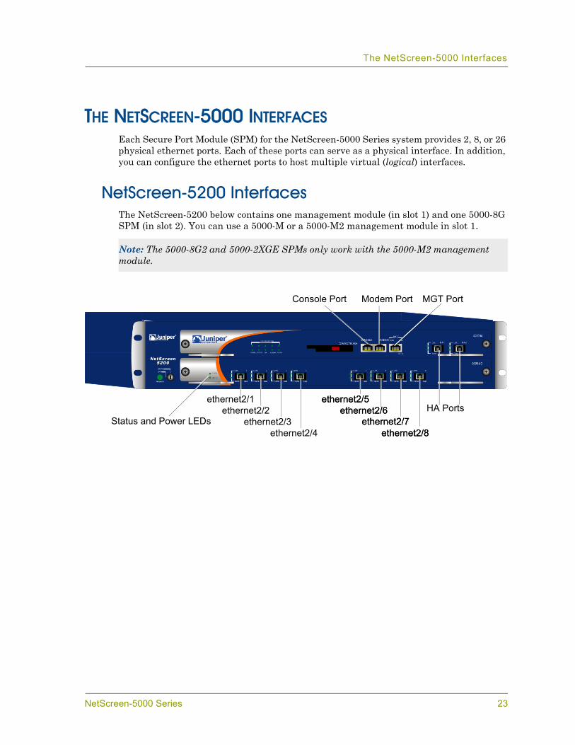
THE NETSCREEN-5000 INTERFACESEach Secure Port Module (SPM) for the NetScreen-5000 Series system provides 2, 8, or 26 physical ethernet ports. Each of these ports can serve as a physical interface. In addition, you can configure the ethernet ports to host multiple virtual (logical) interfaces.
NetScreen-5200 InterfacesThe NetScreen-5200 below contains one management module (in slot 1) and one 5000-8G SPM (in slot 2). You can use a 5000-M or a 5000-M2 management module in slot 1.
Note: The 5000-8G2 and 5000-2XGE SPMs only work with the 5000-M2 management module.
Status and Power LEDs
MGT Port
ethernet2/1
Modem PortConsole Port
HA Portsethernet2/2ethernet2/3
ethernet2/4
ethernet2/5ethernet2/6
ethernet2/7ethernet2/8
ethernet2/5ethernet2/6
ethernet2/7ethernet2/8
NetScreen-5000 Series 23
Chapter 3 Configuring the Device
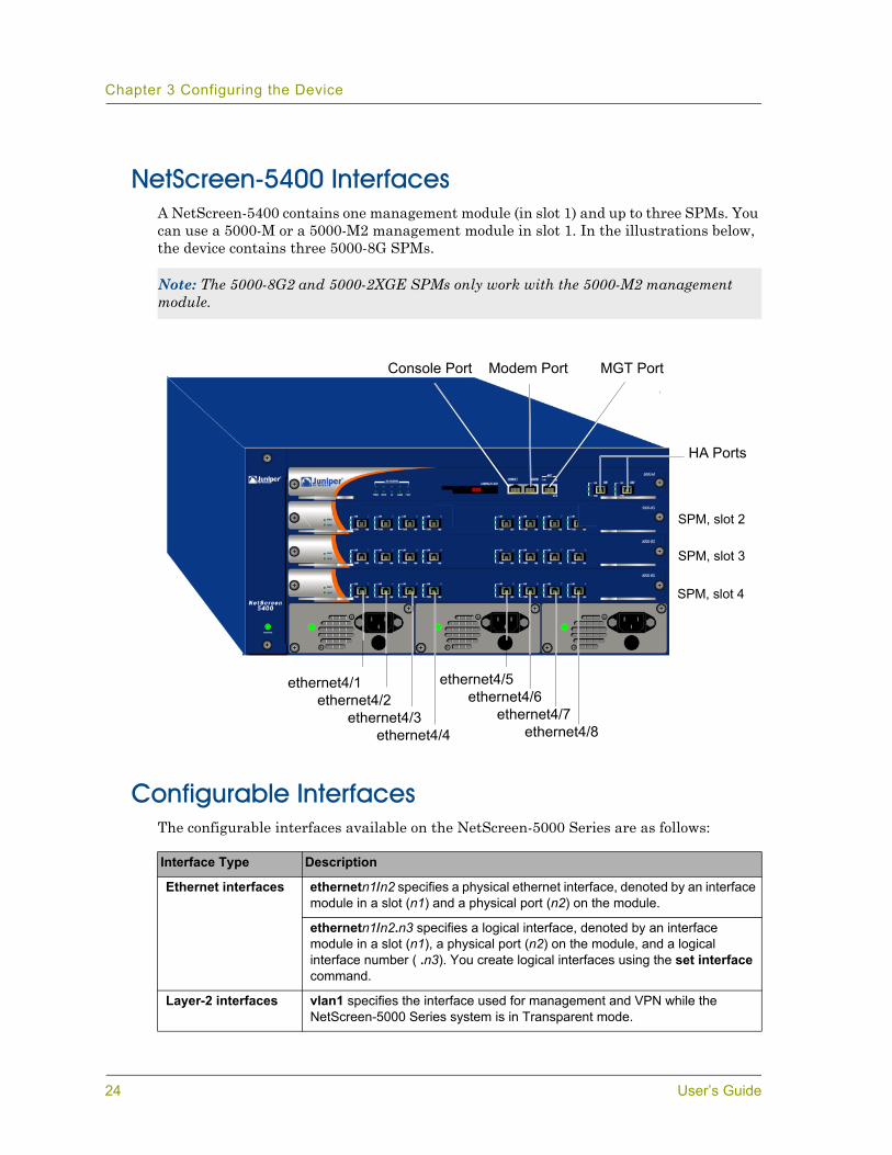
NetScreen-5400 InterfacesA NetScreen-5400 contains one management module (in slot 1) and up to three SPMs. You can use a 5000-M or a 5000-M2 management module in slot 1. In the illustrations below, the device contains three 5000-8G SPMs.
Configurable InterfacesThe configurable interfaces available on the NetScreen-5000 Series are as follows:
Note: The 5000-8G2 and 5000-2XGE SPMs only work with the 5000-M2 management module.
Interface Type Description
Ethernet interfaces ethernetn1/n2 specifies a physical ethernet interface, denoted by an interface module in a slot (n1) and a physical port (n2) on the module.
ethernetn1/n2.n3 specifies a logical interface, denoted by an interface module in a slot (n1), a physical port (n2) on the module, and a logical interface number ( .n3). You create logical interfaces using the set interface command.
Layer-2 interfaces vlan1 specifies the interface used for management and VPN while the NetScreen-5000 Series system is in Transparent mode.
MGT Port
ethernet4/1
Modem PortConsole Port
ethernet4/2ethernet4/3
ethernet4/4
ethernet4/5ethernet4/6
ethernet4/7ethernet4/8
HA Ports
SPM, slot 2
SPM, slot 3
SPM, slot 4
24 User’s Guide

Performing Initial Connection and Configuration
PERFORMING INITIAL CONNECTION AND CONFIGURATIONTo establish the first console session with the NetScreen-5000 Series system, use a vt100 terminal emulator program through the provided RJ-45/DB9 serial port connector.
Establishing a Terminal Emulator ConnectionTo establish an initial console session:
1. Plug the DB-9 end of the supplied RJ-45/DB-9 serial cable into the serial port of your workstation. (Be sure that the DB-9 is seated properly and secured with the screws.)
2. Plug the RJ-45 end of the cable into the Console port of the NetScreen-5000 Series system. (Be sure that the RJ-45 clip snaps into the port and is seated properly.)
3. Launch a Command Line Interface (CLI) session between your workstation and the NetScreen-5000 Series system using a standard serial terminal emulation program such as Hilgraeve HyperTerminal (provided with the Microsoft Windows operating system). The settings should be as follows:
• Baud Rate to 9600
• Parity to No
• Data Bits to 8
• Stop Bit to 1
• Flow Control to none4. At the HyperTerminal window, press the enter key to display the login prompt.5. At the login prompt, type netscreen.6. At the password prompt, type netscreen.
7. (Optional) By default, the console times out and terminates automatically after 10 minutes of idle time. To change this timeout interval, execute the following command:
set console timeout number
where number is the length of idle time in minutes before session termination. To prevent any automatic termination, specify a value of 0.
Tunnel interfaces tunnel.n specifies a tunnel interface. Use this interface for VPN traffic.
Function interfaces mgt specifies a dedicated management interface bound to the MGT zone.
ha1 and ha2 specify the names of the dedicated HA ports.
Note: Use lowercase letters only. Both login and password are case-sensitive.
NetScreen-5000 Series 25
Chapter 3 Configuring the Device
Upgrading the Firmware During the Boot Process1. Connect your computer to the NetScreen-5000 Series system:
a. Using a serial cable, connect the serial port on your computer to the console port on the NetScreen-5000 Series system. This connection, in combination with a terminal application, enables you to manage the NetScreen device.
b. Using an Ethernet cable, connect the network port on your computer to the management port on the NetScreen-5000 Series system. This connection enables the transfer of data between the computer, the TFTP server, and the NetScreen device.
2. Make sure that you have the new ScreenOS image file stored in the TFTP server directory on your computer. For information on obtaining the new firmware, see the NetScreen Concepts & Examples Reference Guide.
3. Run the TFTP server on your computer by double-clicking on the TFTP server application. You can minimize its window but it must be active in the background.
4. Log in to the NetScreen-5000 Series system using a terminal emulator such as HyperTerminal. See “Establishing a Terminal Emulator Connection” on page 25. Log in as the root admin or an admin with read-write privileges.
5. Power on or reboot the NetScreen-5000 Series system.6. Keep your eyes on the terminal emulator screen, then when you see “Hit any key
to load new firmware”, press any key on your computer keyboard to interrupt the startup.
7. At the Boot File Name prompt, enter the file name of the ScreenOS firmware you want to load.
8. At the Self IP Address prompt, enter the IP address of the NetScreen-5000 Series system that is used to communicate to the TFTP server.
9. At the TFTP IP Address prompt, enter the IP address of the TFTP server.
An indication that the firmware is loading successfully is the display of the series of “rtatatatatata...” running on the terminal emulator screen and a series of symbols running on the TFTP server window. When the firmware installation is complete, a message informs you of the success of the installation.
10. Answer Yes to the following question: “Program to on-board flash” ([y]/n)”
Answering “yes” saves the firmware you installed to flash memory.11. Answer Yes to the following question: “Run downloaded program? ([y]/n)”
Answering “yes” instructs the NetScreen-5000 Series system to start running the new ScreenOS firmware.
Note: If you do not interrupt the NetScreen-5000 Series system in time, it proceeds to load the firmware saved in flash memory.
26 User’s Guide
Performing Initial Connection and Configuration
Changing Your Admin Name and PasswordBecause all NetScreen products use the same admin name and password (netscreen), it is highly advisable to change your admin name and password immediately. Enter the following commands:set admin name name_strset admin password pswd_strsave
For information on creating different levels of administrators, see the NetScreen Concepts & Examples ScreenOS Reference Guide.
Setting Port and Interface IP AddressesThrough the CLI, you can execute commands that set IP address and subnet mask values for most of the physical interfaces.
Viewing Current Interface SettingsTo begin the configuration process, it is advisable to view existing port settings by executing the following command:get interface
This command displays current port names, IP addresses, MAC addresses, and other useful information.
Setting the IP Address of the Management InterfaceThe default IP address and subnet mask settings for the MGT interface are 192.168.1.1 and 255.255.255.0, respectively. To access the MGT interface, you must change the IP address and subnet mask of the MGT interface to match your current network. NetScreen recommends using the MGT interface exclusively for out of band management.
To set the IP address of the MGT interface:1. Choose an unused IP address within the current address range of your Local
Area Network.2. Set the MGT interface to this unused IP address by executing the following
command:set interface mgt ip ip_addr/mask
Note: The MGT interface is on the 5000-M or 5000-M2 management modules, which are always in slot 1.
NetScreen-5000 Series 27
Chapter 3 Configuring the Device
For example, to set the IP address and subnet mask of the MGT interface to 10.100.2.183 and 16, respectively:set interface mgt ip 10.100.2.183/16
3. To confirm the new port settings, execute the following command:get interface mgt
Setting the IP Address for the Trust Zone InterfaceThe NetScreen-5000 Series system usually communicates with your protected network through an interface bound to the Trust zone. To allow an interface to communicate with internal devices, you must assign it the IP address and subnet mask for your protected network.
To set up the ethernet2/2 interface to communicate with your trusted network:1. Determine the IP address and subnet mask of your trusted network.2. Set the ethernet2/2 interface to the Trust zone by executing the following
command:set interface ethernet2/2 zone trust
3. Set the IP address and subnet mask by executing the following command:set interface ethernet2/2 ip ip_addr/mask
where ip_addr is the IP address and mask is the subnet mask. For example, to set the IP address and subnet mask of the ethernet2/2 interface to10.250.2.1/16:set interface ethernet2/2 ip 10.250.2.1/16
4. (Optional) To confirm the new port settings, execute the following command:get interface ethernet2/2
Setting the IP Address for the Untrust Zone InterfaceThe NetScreen-5000 Series system usually communicates with external (untrusted) devices through an interface bound to the Untrust zone. To allow an interface to communicate with external devices, you must assign it a public IP address.
To set up the ethernet2/3 interface to communicate with external devices:1. Choose an unused public IP address and subnet mask.2. Set the ethernet2/3 interface to the Untrust zone by executing the following
command:set interface ethernet2/3 zone untrust
28 User’s Guide
Configuring the Device for Telnet and WebUI Sessions
3. Set the IP address and subnet mask by executing the following command:set interface ethernet2/3 ip ip_addr/mask
where ip_addr is the IP address and mask is the subnet mask. For example, to set the IP address and subnet mask of the ethernet2/3 interface to172.16.20.1/16:set interface ethernet2/3 ip 172.16.20.1/16
4. (Optional) To confirm the new interface settings, execute the following command:get interface ethernet2/3
Allowing Outbound TrafficBy default, the NetScreen-5000 Series system does not allow inbound or outbound traffic, nor does it allow traffic to or from the DMZ. To permit (or deny) traffic, you must create access policies.
The following CLI command creates an access policy that permits all kinds of outbound traffic, from any host in your trusted LAN to any device on the untrusted network.set policy from trust to untrust any any any permit
Save your access policy configuration with the following command:save
CONFIGURING THE DEVICE FOR TELNET AND WEBUI SESSIONSIn addition to terminal emulator programs, you can use Telnet (or dialup) to establish console sessions with a NetScreen-5000 Series system. You can also start management sessions using the NetScreen WebUI, a web-based GUI management application.
Starting a Console Session Using TelnetTo establish a Telnet session with the NetScreen-5000 Series system:
1. Connect an RJ-45 cable from the MGT interface to the internal switch, router, or hub in your LAN.
2. Open a Telnet session, specifying the current MGT interface IP address. For example, in Windows, click Start > Run , enter telnet ip_addr (where ip_addr is the address of the MGT interface), then click OK.
Important: Your network might require a more restrictive policy than the one created in the example above. The example is NOT a requirement for initial configuration. For detailed information about access policies, see the NetScreen Concepts & Examples ScreenOS Reference Guide.
NetScreen-5000 Series 29
Chapter 3 Configuring the Device
For example, if the MGT interface has an address of 10.100.2.183, then enter:
telnet 10.100.2.1833. At the Username prompt, type your user name (default is netscreen).4. At the Password prompt, type your password (default is netscreen).
5. (Optional) By default, the console times out and terminates automatically after 10 minutes of idle time. To change this timeout interval, execute the following command:
set console timeout number
where number is the length of idle time in minutes before session termination. To prevent any automatic termination, specify a value of 0.
Starting a Console Session Using DialupEach NetScreen-5000 Series system provides a modem port that allows you to establish a remote console session using a dialup connection through a 9600 bps modem. Dialing into the modem establishes a dialup console connection.
Establishing a GUI Management SessionTo access a NetScreen-5000 Series system with the WebUI management application:
1. Connect your computer (or your LAN hub) to the MGT interface using a Category-5 Ethernet cable. (The MGT interface is on the 5000-M or 5000-M2 management modules, which always reside in slot 1.)
2. Launch your browser, enter the IP address of the MGT interface in the URL field, and then press Enter.
Note: Use lowercase letters only. Both username and password are case-sensitive.
Note: The Terminal type for dialup sessions must be vt100. For example, in Hilgreave HyperTerminal (a commonly-used terminal application), select the File menu. select Properties, select the Settings tab, and then under the Emulation drop-down menu, select VT100.
30 User’s Guide

Configuring the Chassis Alarm
For example, if you assigned the MGT interface an IP address of 10.100.2.183/16, then enter:http://10.100.2.183
The NetScreen WebUI software displays the login prompt.
3. Enter netscreen in both the Admin Name and Password fields, and then click Login. (Use lowercase letters only. The Admin Name and Password fields are both case sensitive.)
The NetScreen WebUI application window appears.
CONFIGURING THE CHASSIS ALARMThe NetScreen-5000 Series system allows you to configure the chassis alarm, an audible warning that sounds when a system failure or hazardous event occurs. To determine which failures and events trigger the chassis alarm:
1. Configure the audible alarms by executing the following command:set chassis audible-alarm string
where string can be any of the following keywords:
2. After configuring the alarm, it is advisable to view alarm environment information by executing the following command:
get chassis
all Enables all chassis alarms.
battery Sets the chassis alarm to sound when a battery fails.
fan-failed Sets the chassis alarm to sound when a fan fails.
power-failed Sets the chassis alarm to sound when a power supply fails.
temperature Sets the chassis alarm to sound when the temperature goes outside of the acceptable range.
NetScreen-5000 Series 31
Chapter 3 Configuring the Device
CONFIGURING JUMBO FRAMESThe 5000-8G2 and 5000-2XGE SPMs support jumbo frames that are up to 9,830 bytes. To set jumbo frames, use the set environment max-frame-size=9830 CLI command. You must reboot the system before this feature can take effect.
CONFIGURING AGGREGATE INTERFACESThe NetScreen-5000 Series system allows you to combine two or more physical ports into a single virtual port. This virtual port is known as an aggregate interface. Only Secure Port Modules (SPMs) support this feature.
• On a 5000-8G SPM, you can create up to four aggregate interfaces.• On a 5000-8G2 SPM, you can create up to four aggregate interfaces.• On a 5000-2G24FE SPM, you can create up to five aggregate interfaces.
The 5000-8G SPM and 5000-8G2 SPM support only certain combinations of ports for aggregate interfaces. For example, a 5000-8G SPM residing in slot 2 only supports the following port combinations:
• ethernet2/1 and ethernet2/2• ethernet2/3 and ethernet2/4• ethernet2/5 and ethernet2/6• ethernet2/7 and ethernet2/8
You must assign one of the following names to the aggregate interface: aggregate1, aggregate2, aggregate3, or aggregate4.
In the following example, you combine two Gigabit Ethernet mini-GBIC ports, each running at 1 Gbps, into an aggregate interface running at 2 Gbps. The aggregate interface consists of Ethernet ports 1 and 2 on a 5000-8G SPM (residing in slot 2).
To create the aggregate interface:1. (Optional) To see what physical ports are available on your NetScreen-5000
Series system:get interface
2. To create an aggregate interface name: set interface string zone zonename
where string is a legal aggregate interface name (aggregate1, aggregate2, aggregate3, or aggregate4).
For example, to create the aggregate interface name aggregate1:set interface aggregate1 zone zonename
3. To assign ports ethernet2/1 and ethernet2/2 to the aggregate1 interface name:set interface ethernet2/1 aggregate aggregate1set interface ethernet2/2 aggregate aggregate1
32 User’s Guide
Using CLI Commands to Reset the Device
4. (Optional) To see the updated port list and details about the new aggregate interface:get interfaceget interface aggregate1
Notice that the listing contains aggregate1, an aggregate interface comprised of ethernet2/1 and ethernet2/2. This aggregate interface runs with a throughput rate of 2 Gbps. Use the following command to bind the aggregate interface, aggregate1, to the trust zone:
set interface aggregate1 zone trust
USING CLI COMMANDS TO RESET THE DEVICEIf you lose the admin password, then you can use the following procedure to reset the NetScreen-5000 Series system to its default settings. This procedure destroys any existing configurations, but restores access to the device. To perform this operation, you need to make a console connection, as described in “Establishing a Terminal Emulator Connection” on page 25.
1. At the login prompt, type the serial number of the NetScreen-5000 Series system.
2. At the password prompt, type the serial number again.
The following message appears:
!!! Lost Password Reset !!! You have initiated a command to reset the device to factory defaults, clearing all current configuration, keys and settings. Would you like to continue? y/[n]
Note: As with most other interfaces, you must assign the aggregate interface an IP address so that other nodes on the network can reach it.
Warning: Resetting the NetScreen-5000 Series system deletes all existing configuration settings, and the firewall and VPN services is rendered inoperative.
Note: After you successfully reset and reconfigure the NetScreen-5000 Series, you should back up the new configuration setting. As a precaution against lost passwords, you should back up a new configuration that contains the NetScreen default password. This will ensure a quick recovery of a lost configuration. You should change the password on the system as soon as possible. For detailed information about configuration backups, see the System Parameters section in the NetScreen Concepts & Examples ScreenOS Reference Guide.
Note: By default the device recovery feature is enabled. You can disable it by entering the following CLI command: unset admin device-reset.
NetScreen-5000 Series 33

Chapter 3 Configuring the Device
3. Press the y key.
The following message appears:
!! Reconfirm Lost Password Reset !! If you continue, the entire configuration of the device will be erased. In addition, a permanent counter will be incremented to signify that this device has been reset. This is your last chance to cancel this command. If you proceed, the device will return to factory default configuration, which is: System IP: 192.168.1.1; username: netscreen; password: netscreen. Would you like to continue? y/[n]
4. Press the y key to reset the device.
You can now login in using netscreen as the default admin name and password.
34 User’s Guide
4Chapter 4
Servicing the DeviceThis chapter details service and maintenance of various components in yourNetScreen-5000 Series system. Topics in this chapter include:
• “Removing and Reseating Modules” on page 36• “Replacing a DC Power Supply” on page 36• “Replacing an AC Power Supply” on page 37• “Replacing the Fan Module” on page 37• “Connecting and Disconnecting Gigabit Ethernet Cables” on page 43• “Removing and Installing a Mini-GBIC Transceiver” on page 43
NetScreen-5000 Series 35

Chapter 4 Servicing the Device
REMOVING AND RESEATING MODULESAlthough NetScreen-5000 Series modules are pre-installed before shipping, you may find it necessary to remove or reseat modules to suit the special security needs of your network.
To remove a module from a NetScreen-5000 Series system:1. Release the module from the chassis by loosening the screws.2. Rotate the ejector/injector levers to disengage the module from the backplane.3. Gently slide the module card out of the chassis.
To install a module in a NetScreen-5000 Series system:1. Be sure the module is right-side-up and the ejector/injector levers are extended.2. Slide the module into the appropriate slot of the chassis, until it is seated in the
backplane.3. To secure the module in the chassis, close the ejector/injector levers by pushing
on them toward the center of the module.4. Tighten the screws using a #2 Phillips-head screwdriver.
REPLACING A DC POWER SUPPLY
To replace a DC power supply:1. Turn off the power supply.2. Loosen the retaining screws on the terminal block.3. Remove the feed wires.4. Turn the thumbscrew counterclockwise to release the power supply.5. Lift and grip the lever, and then gently pull the power supply straight out.6. Insert the new power supply into the bay.7. Secure the power supply in place by tightening the thumbscrew clockwise.8. Reconnect the wires as explained in “Installing and Wiring a DC Power Supply”
on page 17.
Warning: Always be sure the chassis power switch is off before you remove or install a Secure Port Module (SPM) or management module.
Warning: Before replacing a power supply, you MUST shut off current to the DC feed wires that lead to the power supply. Also, be sure that the power switch is in the off position (right side pressed in).
36 User’s Guide

Replacing an AC Power Supply
REPLACING AN AC POWER SUPPLYTo replace an AC power supply:
1. Turn off the power supply.2. Lift the AC power cord retainer clip.3. Unplug the cord from the power supply.4. Turn the thumbscrew counterclockwise to release the power supply.5. Lift and grip the lever, and then gently pull the power supply straight out.6. Insert the new power supply into the bay.7. Secure the power supply in place by tightening the thumbscrew clockwise.8. Lift the retainer clip, and then plug the power cord into the power supply.9. Press the retainer clip over the cord, securing it in place.
REPLACING THE FAN MODULEThe front panel of each device includes an air vent for cooling purposes. The NetScreen-5000 Series fan modules differ according to the device model:
• The NetScreen-5200 fan module has three fans• The NetScreen-5400 fan module has two fans
When a fan or fan module fails, the Fan LED glows red, and the system generates an event alarm and a SNMP trap. Although a NetScreen-5000 Series system can operate with a fan out of service, it is advisable to replace the fan module as soon as possible.
When you remove the fan module, you must reinstall it (or replace it) within two minutes, or system failure can occur.
If the temperature alarm continues to display, we recommend inspecting the fan filter. To remove a filter cover and replace a filter, use the procedures described in this section.
Warning: If the device becomes too hot, then the system shuts down automatically.
Note: During the one-year warranty period, you can obtain a replacement fan module by contacting Juniper Networks Technical support. After the warranty period, contact the Juniper Networks Sales department to renew your support contract.
Note: Depending on the working environment where the device is located, we recommend changing the fan filter every six months. The fan filter SKU number is NS-5200-FLTR or NS-5400-FLTR.
NetScreen-5000 Series 37

Chapter 4 Servicing the Device
NetScreen-5200 Fan Module
To remove the fan module on a NetScreen-5200:1. Pull the fan lever until it is fully extended.2. Grip the sides, then gently slide the assembly straight out.
3. Insert the new fan module in the fan bay, then push it straight in.4. Secure the fan module in place by pushing the fan lever flat against the front
panel.
Warning: Do not remove the fan module while the fans are still spinning.
Fan Lever
Fan Front Fan Module
38 User’s Guide
Replacing the Fan Module
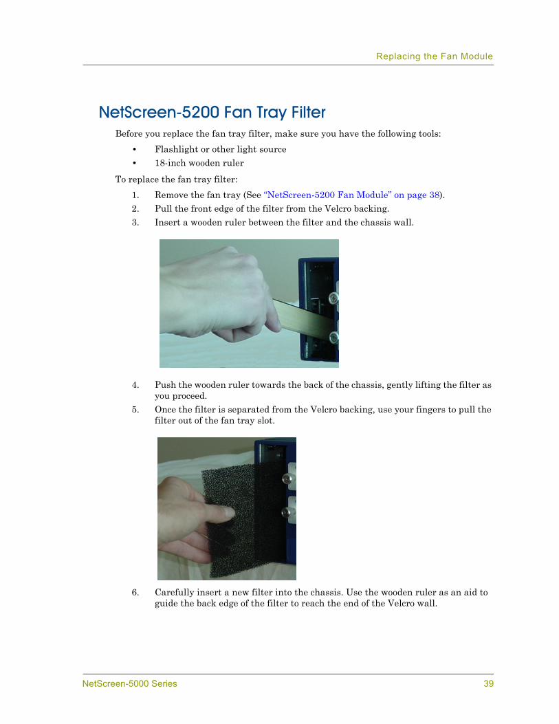
NetScreen-5200 Fan Tray FilterBefore you replace the fan tray filter, make sure you have the following tools:
• Flashlight or other light source• 18-inch wooden ruler
To replace the fan tray filter:1. Remove the fan tray (See “NetScreen-5200 Fan Module” on page 38).2. Pull the front edge of the filter from the Velcro backing.3. Insert a wooden ruler between the filter and the chassis wall.
4. Push the wooden ruler towards the back of the chassis, gently lifting the filter as you proceed.
5. Once the filter is separated from the Velcro backing, use your fingers to pull the filter out of the fan tray slot.
6. Carefully insert a new filter into the chassis. Use the wooden ruler as an aid to guide the back edge of the filter to reach the end of the Velcro wall.
NetScreen-5000 Series 39
Chapter 4 Servicing the Device
7. Once the filter is fully inserted, push the wooden ruler against the filters surface several times to insure that the filter is secure against the chassis wall.
8. Insert the fan tray into the chassis.9. Lock the fan lever.
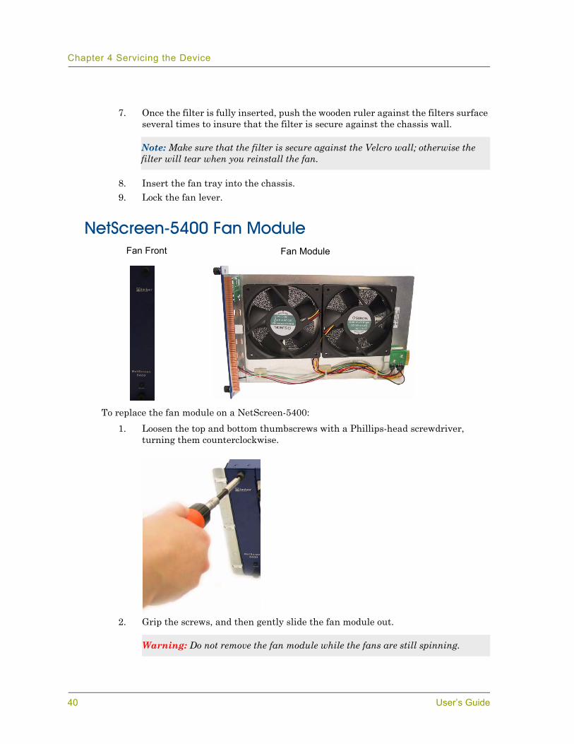
NetScreen-5400 Fan Module
To replace the fan module on a NetScreen-5400:1. Loosen the top and bottom thumbscrews with a Phillips-head screwdriver,
turning them counterclockwise.
2. Grip the screws, and then gently slide the fan module out.
Note: Make sure that the filter is secure against the Velcro wall; otherwise the filter will tear when you reinstall the fan.
Warning: Do not remove the fan module while the fans are still spinning.
Fan Front Fan Module
40 User’s Guide
Replacing the Fan Module
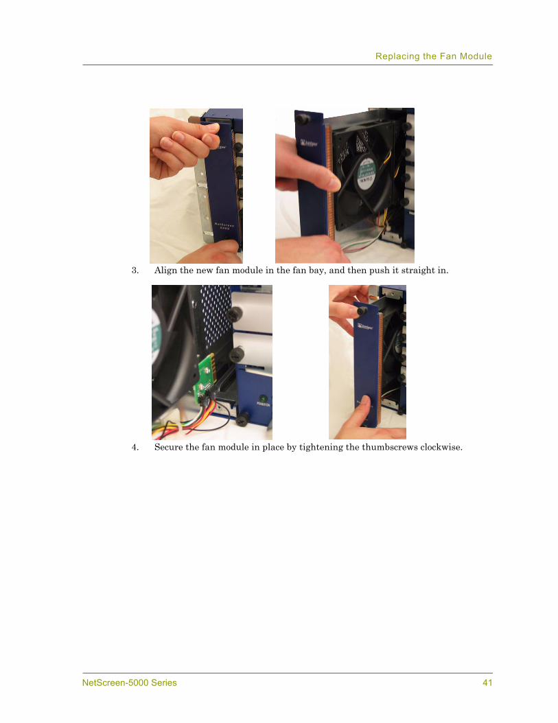
3. Align the new fan module in the fan bay, and then push it straight in.
4. Secure the fan module in place by tightening the thumbscrews clockwise.
NetScreen-5000 Series 41
Chapter 4 Servicing the Device
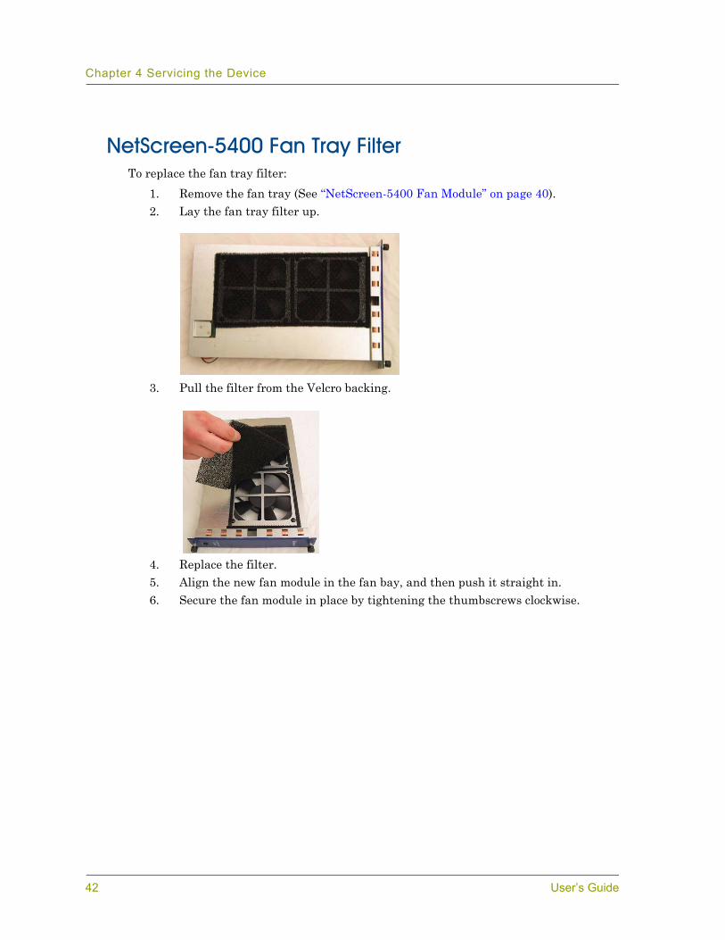
NetScreen-5400 Fan Tray FilterTo replace the fan tray filter:
1. Remove the fan tray (See “NetScreen-5400 Fan Module” on page 40).2. Lay the fan tray filter up.
3. Pull the filter from the Velcro backing.
4. Replace the filter.5. Align the new fan module in the fan bay, and then push it straight in.6. Secure the fan module in place by tightening the thumbscrews clockwise.
42 User’s Guide
Connecting and Disconnecting Gigabit Ethernet Cables
CONNECTING AND DISCONNECTING GIGABIT ETHERNET CABLES
To connect a Gigabit Ethernet cable to a mini-GBIC connector transceiver port:1. Hold the cable clip firmly but gently between your thumb and forefinger, with
your thumb on top of the clip and your finger under the clip. (Do not depress the clip ejector on top of the clip.)
2. Slide the clip into the transceiver port until it clicks into place. Because the fit is close, you may have to apply some force to seat the clip. Apply force evenly and gently to avoid clip breakage.
To remove the cable from the transceiver port:1. Make sure the black transceiver ejector under the port is not pressed in;
otherwise, when you attempt to remove the cable, the transceiver might come out with the cable still attached.
2. Hold the cable clip firmly but gently between your thumb and forefinger, with your thumb on top of the clip and your finger under the clip.
3. Use your thumb to gently press the clip ejector on top of the clip, down, and then forward. This action loosens the clip from the transceiver port.
4. Pull the clip from the transceiver port.
REMOVING AND INSTALLING A MINI-GBIC TRANSCEIVERTo remove a mini-GBIC transceiver from a module:
1. Push in the black ejector (located on the underside of the transceiver) until it locks into place, disengaging the transceiver.
2. Grasp the transceiver at both sides, and then pull the transceiver toward you to remove it from the module.
To install a mini-GBIC transceiver into a module:1. Grasp the transceiver with the label facing up, and then insert it into the
transceiver slot until seated. 2. Check to see if the black transceiver ejector extends fully out to the front of the
ejector slot, flush with the port portion of the transceiver.
NetScreen-5000 Series 43

Chapter 4 Servicing the Device
44 User’s Guide

AAppendix A
SpecificationsThis appendix provides general system specifications for the NetScreen-5000 Series.
• “NetScreen-5200 Attributes” on page A-II• “NetScreen-5400 Attributes” on page A-II• “Electrical Specification” on page A-II• “NEBS Certifications” on page A-III• “Safety Certifications” on page A-III• “EMI Certifications” on page A-III• “Connectors” on page A-III
NetScreen-5000 Series I
Appendix A Specifications
NETSCREEN-5200 ATTRIBUTESHeight: 3.4 inches (8.6 cm)
Depth: 19.5 inches (49.5 cm)
Width: 17.5 inches (44.5 cm)
Weight: 32 pounds (without power supply) (15 kg)
NETSCREEN-5400 ATTRIBUTESHeight: 8.62 inches (21.89 cm)
Depth: 14 inches (35 cm)
Width: 17.5 inches (44.5 cm)
Weight: 42 pounds (without power supply) (19 kg)
ELECTRICAL SPECIFICATIONAC voltage: 100-240 VAC +/- 10%
DC voltage: -36 to -60 VDC
AC Watts: 150 Watts
DC Watts: 150 Watts
Fuse Rating: AC: 3.15 Amps / 250 Volts
DC: 6 Amps / 250 Volts (NetScreen-5200) and 12 Amps / 250 Volts (NetScreen-5400)
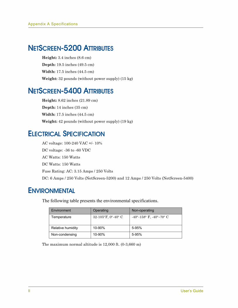
ENVIRONMENTALThe following table presents the environmental specifications.
The maximum normal altitude is 12,000 ft. (0-3,660 m)
Environment Operating Non-operating
Temperature 32-105°F, 0°-40° C -40°-158° F, -40°−70° C
Relative humidity 10-90% 5-95%
Non-condensing 10-90% 5-95%
II User’s Guide
NEBS CERTIFICATIONSLevel 3 NetScreen-5200 with DC power supply.
GR-63-Core: NEBS, Environmental Testing
GR-1089-Core: EMC and Electrical Safety for Network Telecommunications Equipment
SAFETY CERTIFICATIONSUL, CUL, CSA, CE, CB
EMI CERTIFICATIONSFCC class A, CE class A, C-Tick, VCCI class A
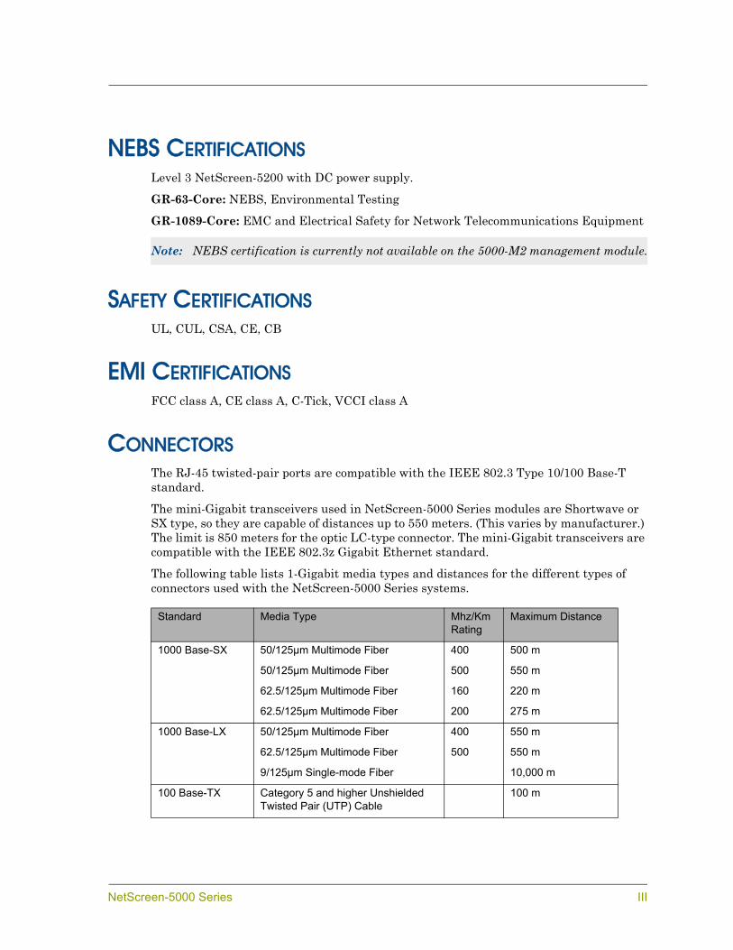
CONNECTORSThe RJ-45 twisted-pair ports are compatible with the IEEE 802.3 Type 10/100 Base-T standard.
The mini-Gigabit transceivers used in NetScreen-5000 Series modules are Shortwave or SX type, so they are capable of distances up to 550 meters. (This varies by manufacturer.) The limit is 850 meters for the optic LC-type connector. The mini-Gigabit transceivers are compatible with the IEEE 802.3z Gigabit Ethernet standard.
The following table lists 1-Gigabit media types and distances for the different types of connectors used with the NetScreen-5000 Series systems.
Note: NEBS certification is currently not available on the 5000-M2 management module.
Standard Media Type Mhz/Km Rating
Maximum Distance
1000 Base-SX 50/125µm Multimode Fiber 400 500 m
50/125µm Multimode Fiber 500 550 m
62.5/125µm Multimode Fiber 160 220 m
62.5/125µm Multimode Fiber 200 275 m
1000 Base-LX 50/125µm Multimode Fiber 400 550 m
62.5/125µm Multimode Fiber 500 550 m
9/125µm Single-mode Fiber 10,000 m
100 Base-TX Category 5 and higher Unshielded Twisted Pair (UTP) Cable
100 m
NetScreen-5000 Series III
Appendix A Specifications
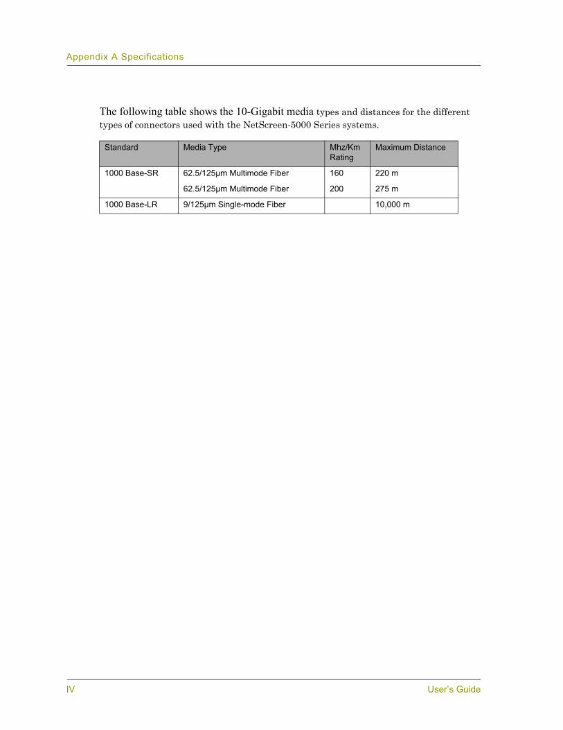
The following table shows the 10-Gigabit media types and distances for the different types of connectors used with the NetScreen-5000 Series systems.
Standard Media Type Mhz/Km Rating
Maximum Distance
1000 Base-SR 62.5/125µm Multimode Fiber 160 220 m
62.5/125µm Multimode Fiber 200 275 m
1000 Base-LR 9/125µm Single-mode Fiber 10,000 m
IV User’s Guide
BAppendix B
Port Descriptions and LED StatusThis appendix provides detail on port descriptions and LED status for the NetScreen-5000 Series modules.
• “Module Port Descriptions” on page B-II• “Module LED Descriptions” on page B-III• “Status LED States” on page B-IV• “Power Supply LEDs” on page B-VI• “Fan LED” on page B-VII
NetScreen-5000 Series I
Appendix B Port Descriptions and LED Status
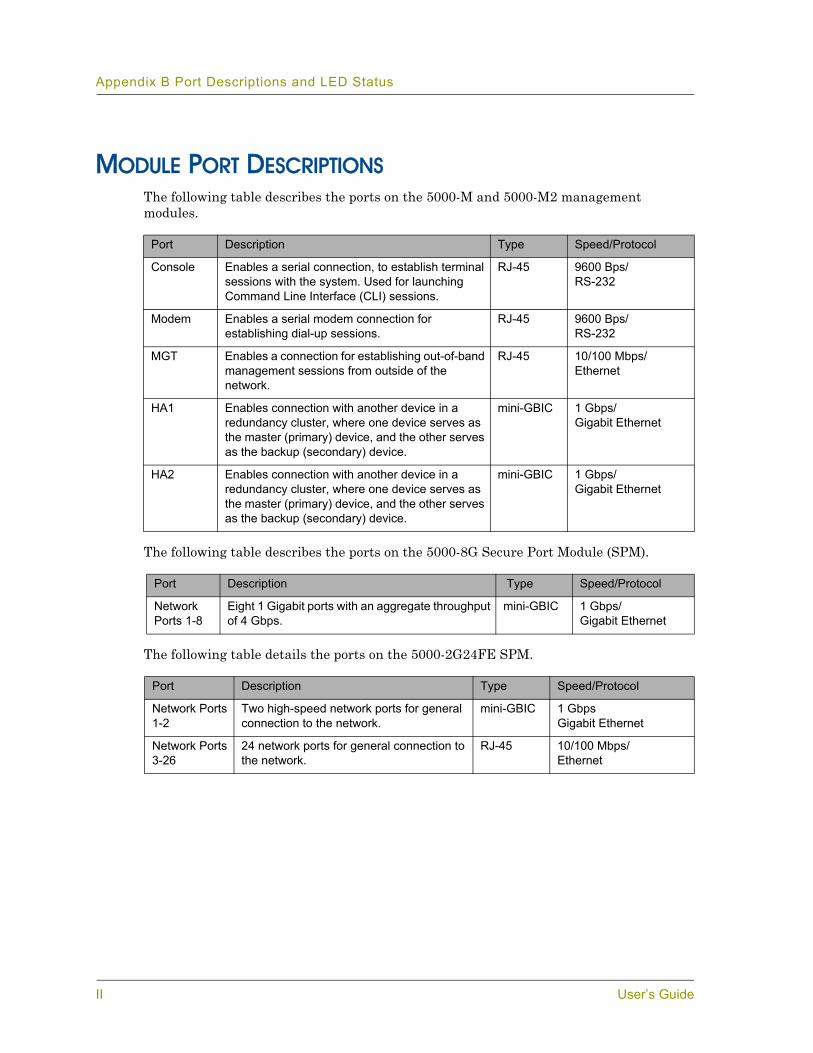
MODULE PORT DESCRIPTIONSThe following table describes the ports on the 5000-M and 5000-M2 management modules.
The following table describes the ports on the 5000-8G Secure Port Module (SPM).
The following table details the ports on the 5000-2G24FE SPM.
Port Description Type Speed/Protocol
Console Enables a serial connection, to establish terminal sessions with the system. Used for launching Command Line Interface (CLI) sessions.
RJ-45 9600 Bps/RS-232
Modem Enables a serial modem connection for establishing dial-up sessions.
RJ-45 9600 Bps/RS-232
MGT Enables a connection for establishing out-of-band management sessions from outside of the network.
RJ-45 10/100 Mbps/Ethernet
HA1 Enables connection with another device in a redundancy cluster, where one device serves as the master (primary) device, and the other serves as the backup (secondary) device.
mini-GBIC 1 Gbps/Gigabit Ethernet
HA2 Enables connection with another device in a redundancy cluster, where one device serves as the master (primary) device, and the other serves as the backup (secondary) device.
mini-GBIC 1 Gbps/Gigabit Ethernet
Port Description Type Speed/Protocol
Network Ports 1-8
Eight 1 Gigabit ports with an aggregate throughput of 4 Gbps.
mini-GBIC 1 Gbps/Gigabit Ethernet
Port Description Type Speed/Protocol
Network Ports 1-2
Two high-speed network ports for general connection to the network.
mini-GBIC 1 GbpsGigabit Ethernet
Network Ports 3-26
24 network ports for general connection to the network.
RJ-45 10/100 Mbps/Ethernet
II User’s Guide

The following table details the ports on the 5000-8G2 SPM.
The following table details the ports on the 5000-2XGE SPM.
MODULE LED DESCRIPTIONSThis section provides descriptions of the LEDs on NetScreen-5000 Series modules. Two types of LEDs exist on the modules:
• Status LEDs. These LEDs reflect certain conditions that exist on the system at large and do not explicitly refer to a given port.
• Port LEDs. These LEDs reflect basic conditions (for example, a link connection status) that exist for a specific port.
Port Description Type Speed/Protocol
Network Ports 1-8
Eight 2-Gigabit ports with an aggregate throughput of 8 Gbps.
mini-GBIC 2 Gbps/Gigabit Ethernet
Port Description Type Speed/Protocol
Network Ports 1 and 2
Two 10-Gigabit Ethernet mini-GBICs with a throughput of 10Gbps.
mini-GBIC 10 Gbps/Gigabit Ethernet
NetScreen-5000 Series III

Appendix B Port Descriptions and LED Status
STATUS LED STATESThis section describes Status LED states on all modules.
Interpreting Status LEDs for the Management Modules
The Status LEDs indicate whether the management module is operating properly. The following table describes the status possibilities for each.
LED LED Color Meaning of the LED
CPU Utilization
green Consists of an array of five LEDs that indicate the current level of CPU utilization. Utilization is defined as the amount of traffic detected on the device at any given time. The CPU utilization LEDs represent the following percentages of possible utilization: 5%, 10%, 25%, 50%, and 90%.
off When all are off, indicates less than 5 percent CPU use.
POWER green Indicates the system is receiving power.
off Indicates the system is not receiving power.
red Indicates the power has a problem.
STATUS blinking green
Indicates the system is operational.
blinking amber
Indicates the system is booting up.
off Indicates the module is not operational.
HA green Indicates the module is a master in a redundancy cluster.
red Indicates the module is ineligible to be a backup.
amber Indicates the module is a backup in a redundancy cluster.
off Indicates that no HA activity has been defined.
ALARM red Indicates an alarm which could mean a system failure.
blinking red Indicates a self-test failure during the bootup process.
off Indicates the system has not detected an event or error at the current time.
FLASH green Indicates the flash card is installed.
blinking green
Indicates flash card activity.
off Indicates no flash card loaded in the flash card slot.
IV User’s Guide
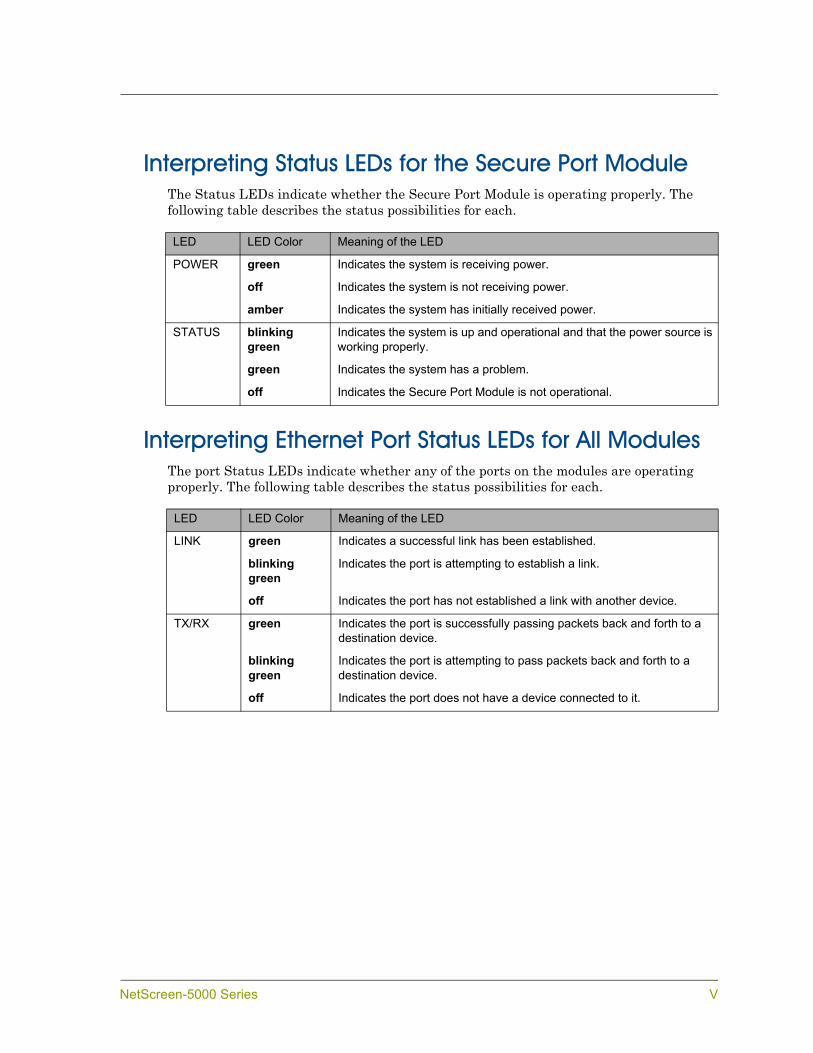
Interpreting Status LEDs for the Secure Port ModuleThe Status LEDs indicate whether the Secure Port Module is operating properly. The following table describes the status possibilities for each.
Interpreting Ethernet Port Status LEDs for All ModulesThe port Status LEDs indicate whether any of the ports on the modules are operating properly. The following table describes the status possibilities for each.
LED LED Color Meaning of the LED
POWER green Indicates the system is receiving power.
off Indicates the system is not receiving power.
amber Indicates the system has initially received power.
STATUS blinking green
Indicates the system is up and operational and that the power source is working properly.
green Indicates the system has a problem.
off Indicates the Secure Port Module is not operational.
LED LED Color Meaning of the LED
LINK green Indicates a successful link has been established.
blinking green
Indicates the port is attempting to establish a link.
off Indicates the port has not established a link with another device.
TX/RX green Indicates the port is successfully passing packets back and forth to a destination device.
blinking green
Indicates the port is attempting to pass packets back and forth to a destination device.
off Indicates the port does not have a device connected to it.
NetScreen-5000 Series V
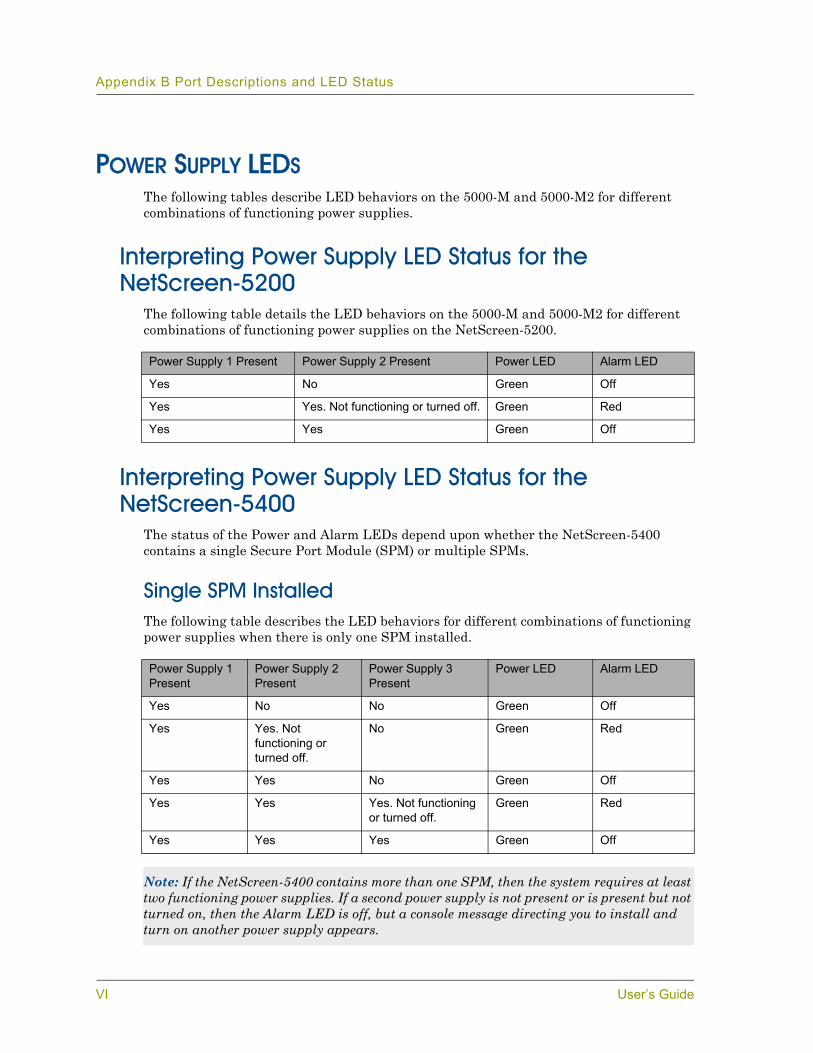
Appendix B Port Descriptions and LED Status
POWER SUPPLY LEDSThe following tables describe LED behaviors on the 5000-M and 5000-M2 for different combinations of functioning power supplies.
Interpreting Power Supply LED Status for the NetScreen-5200
The following table details the LED behaviors on the 5000-M and 5000-M2 for different combinations of functioning power supplies on the NetScreen-5200.
Interpreting Power Supply LED Status for the NetScreen-5400
The status of the Power and Alarm LEDs depend upon whether the NetScreen-5400 contains a single Secure Port Module (SPM) or multiple SPMs.
Single SPM InstalledThe following table describes the LED behaviors for different combinations of functioning power supplies when there is only one SPM installed.
Power Supply 1 Present Power Supply 2 Present Power LED Alarm LED
Yes No Green Off
Yes Yes. Not functioning or turned off. Green Red
Yes Yes Green Off
Power Supply 1 Present
Power Supply 2 Present
Power Supply 3 Present
Power LED Alarm LED
Yes No No Green Off
Yes Yes. Not functioning or turned off.
No Green Red
Yes Yes No Green Off
Yes Yes Yes. Not functioning or turned off.
Green Red
Yes Yes Yes Green Off
Note: If the NetScreen-5400 contains more than one SPM, then the system requires at least two functioning power supplies. If a second power supply is not present or is present but not turned on, then the Alarm LED is off, but a console message directing you to install and turn on another power supply appears.
VI User’s Guide
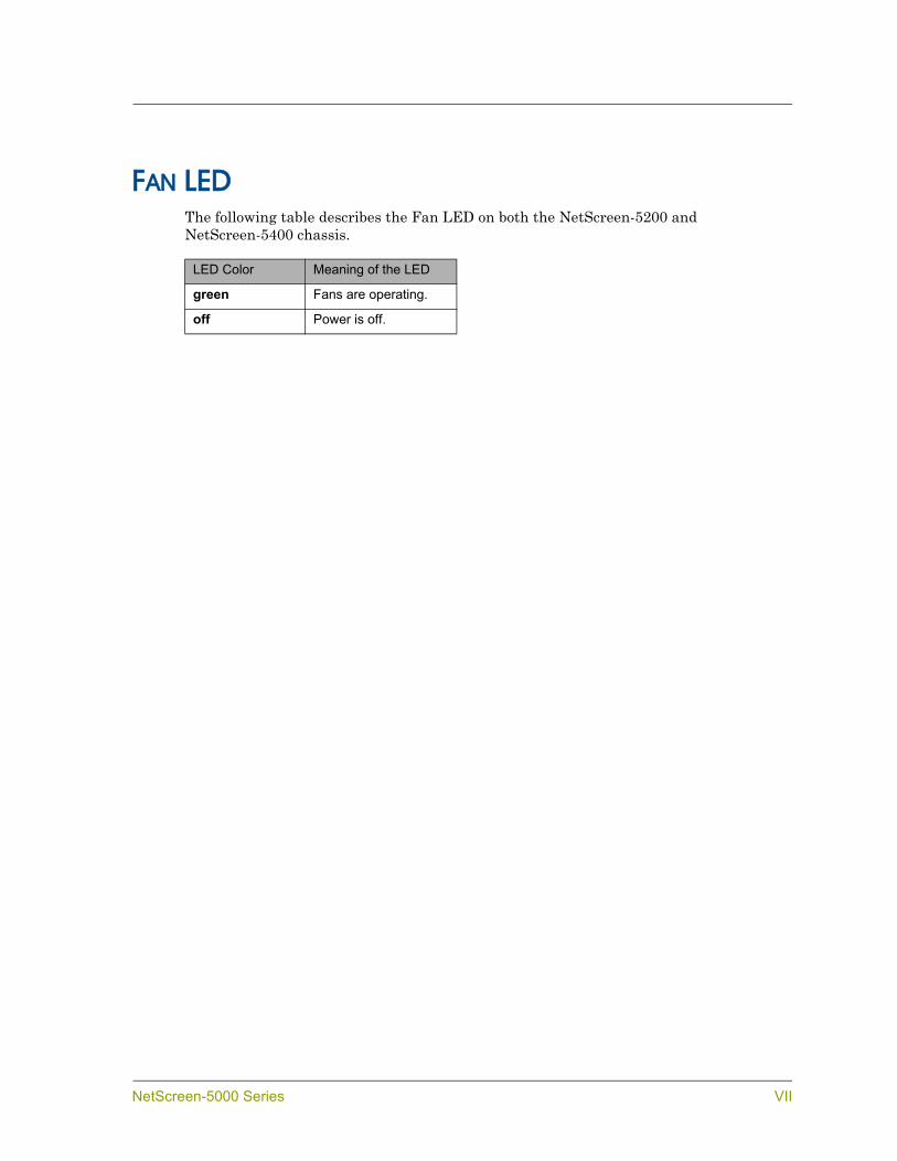
FAN LEDThe following table describes the Fan LED on both the NetScreen-5200 and NetScreen-5400 chassis.
LED Color Meaning of the LED
green Fans are operating.
off Power is off.
NetScreen-5000 Series VII

Appendix B Port Descriptions and LED Status
VIII User’s Guide
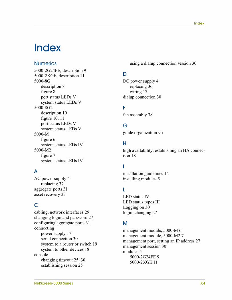
Index
IndexNumerics5000-2G24FE, description 95000-2XGE, description 115000-8G
description 8figure 8port status LEDs Vsystem status LEDs V
5000-8G2description 10figure 10, 11port status LEDs Vsystem status LEDs V
5000-Mfigure 6system status LEDs IV
5000-M2figure 7system status LEDs IV
AAC power supply 4
replacing 37aggregate ports 31asset recovery 33
Ccabling, network interfaces 29changing login and password 27configuring aggregate ports 31connecting
power supply 17serial connection 30system to a router or switch 19system to other devices 18
consolechanging timeout 25, 30establishing session 25
using a dialup connection session 30
DDC power supply 4
replacing 36wiring 17
dialup connection 30
Ffan assembly 38
Gguide organization vii
Hhigh availability, establishing an HA connec-tion 18
Iinstallation guidelines 14installing modules 5
LLED status IVLED status types IIILogging on 30login, changing 27
Mmanagement module, 5000-M 6management module, 5000-M2 7management port, setting an IP address 27management session 30modules 5
5000-2G24FE 95000-2XGE 11
NetScreen-5000 Series IX-I

Index
5000-8G 85000-8G2 10, 115000-M 65000-M2 7allowable slots 5installing 5management module 6secure port modules 7
mountingmid-mount rack installation 16rear and front rack installation 15
NNetScreen publications viiiNetScreen-5000
connecting to a router or switch 19connecting to other devices 18modules 5
NetScreen-5200, about 2NetScreen-5400, about 2
Ppassword
changing 27resetting 33
port settings, viewing 27port status LEDs
5000-2XGE V5000-8G V5000-8G2 V5000-M V5000-M2 V
power suppliesAC
description 4replacing 37
connecting to the system 4
DCground posts 18replacing 36terminal blocks 18wiring 18
installing 17recommendations 3
Rrack
installation guidelines 14mounting 14
replacinga DC power supply 36an AC power supply 37
reset 33
SSecure Port Modules
5000-2G24FE 95000-2XGE 115000-8G 85000-8G2 10, 11
system status LEDs5000-2XGE V5000-8G V5000-8G2 V5000-M IV5000-M2 IV
Ttransparent mode 22
Vventilation 14viewing port settings 27
IX-II User’s Guide


![[MS-PPPI]: PPP Over IrDA Dialup Protocol... · Protocol (PPP Over IrDA Dialup Protocol), and includes contributions from Microsoft, Ericsson, and Nokia. The PPP Over IrDA Dialup Protocol](https://img.dokumen.tips/doc/110x75/5e904da7efdba9511f28b94d/ms-pppi-ppp-over-irda-dialup-protocol-protocol-ppp-over-irda-dialup-protocol.jpg)


![[MS-PPPI]: PPP Over IrDA Dialup Protocol](https://img.dokumen.tips/doc/110x75/61a409ba0dc068626e4d892d/ms-pppi-ppp-over-irda-dialup-protocol.jpg)
