Embed Size (px)
Citation preview
1
2
3
4
5
NESCC Polymer Pipe Task Group (PPTG) 6
Polymer Pipe Codes and Standards for Nuclear 7
Power Plants 8
9
10
Current Status and Recommendations for Future 11
Development 12
13
14
15
16
17
18
19
20
21
22
Preparation of This Report 1
2
This report was prepared by the NESCC Polymer Pipe Task Group (PPTG). Membership on the PPTG 3 was open. Efforts were made to include representatives from standards development organizations 4 (SDO), nuclear plant operators and design, and polyethylene pipe manufacturers that are involved in 5 nuclear power plant construction. 6
7
Convener: The Convener of the PPTG was Aaron M. Forster, Engineering Laboratory, National 8
Institute of Standards and Technology, Gaithersburg (USA) 9
10
11
12
13
14
15
16
17
18
19
20
21
22
23
24
25
26
27
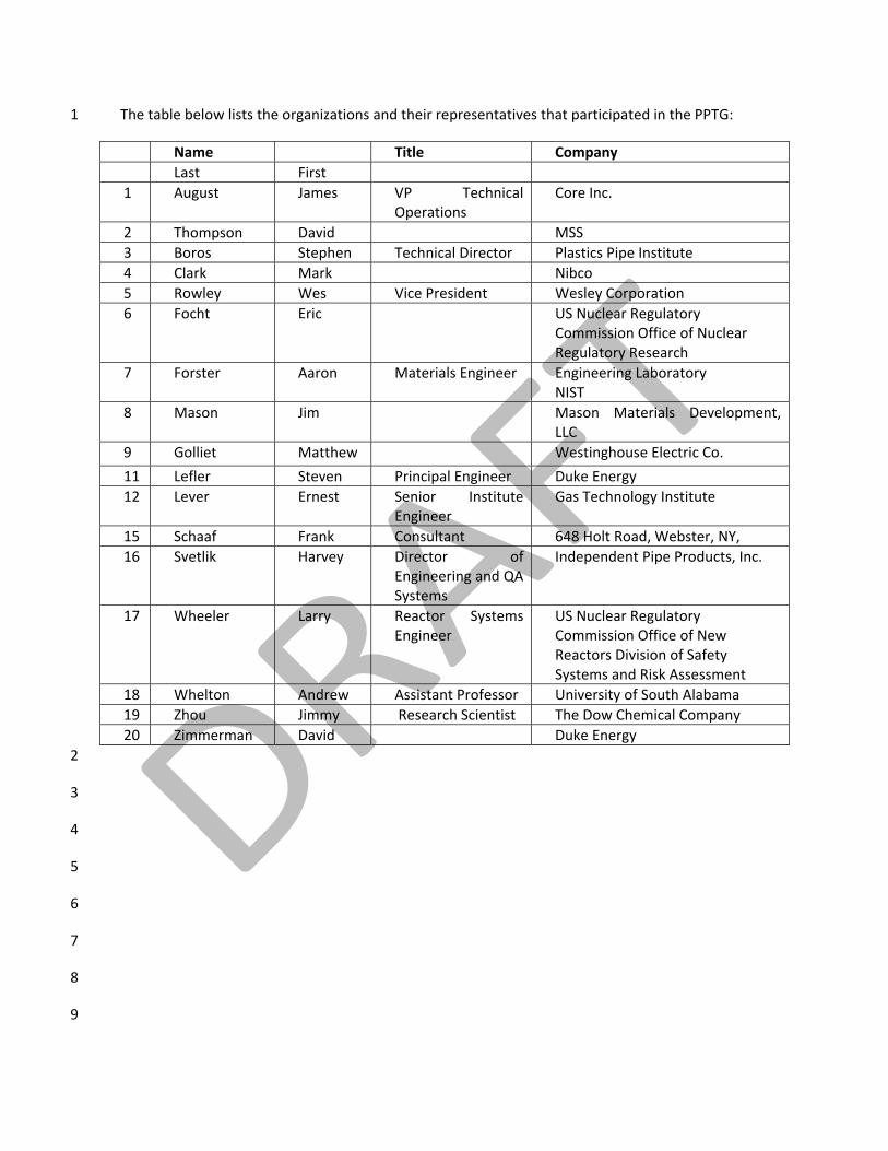
The table below lists the organizations and their representatives that participated in the PPTG: 1
Name Title Company Last First 1 August James VP Technical
Operations Core Inc.
2 Thompson David MSS 3 Boros Stephen Technical Director Plastics Pipe Institute 4 Clark Mark Nibco 5 Rowley Wes Vice President Wesley Corporation 6 Focht Eric US Nuclear Regulatory
Commission Office of Nuclear Regulatory Research
7 Forster Aaron Materials Engineer Engineering Laboratory NIST
8 Mason Jim Mason Materials Development, LLC
9 Golliet Matthew Westinghouse Electric Co.
11 Lefler Steven Principal Engineer Duke Energy 12 Lever Ernest Senior Institute
Engineer Gas Technology Institute
15 Schaaf Frank Consultant 648 Holt Road, Webster, NY, 16 Svetlik Harvey Director of
Engineering and QA Systems
Independent Pipe Products, Inc.
17 Wheeler Larry Reactor Systems Engineer
US Nuclear Regulatory Commission Office of New Reactors Division of Safety Systems and Risk Assessment
18 Whelton Andrew Assistant Professor University of South Alabama 19 Zhou Jimmy Research Scientist The Dow Chemical Company 20 Zimmerman David Duke Energy 2
3
4
5
6
7
8
9
Table of Contents 1
1 Introduction ______________________________________________________________ 6 2
2 Objectives and Overview ___________________________________________________ 7 3
3 Definitions _______________________________________________________________ 9 4
4 Standards Development Organizations and Nuclear Construction Codes ____________ 12 5
5 Review of Current Standards _______________________________________________ 13 6
5.1 Standards for Pipe Resins _____________________________________________________ 13 7
5.2 Standards for Design Basis and Strength Requirements _____________________________ 15 8
5.3 Standards for Valves and Fittings _______________________________________________ 18 9
5.4 Standards for Joining _________________________________________________________ 20 10 5.4.1 Butt Fusion _______________________________________________________________________ 20 11 5.4.2 Electrofusion _____________________________________________________________________ 25 12
5.5 Long‐term Performance Standards _____________________________________________ 27 13 5.5.1 Standards for PE Compounds ________________________________________________________ 27 14 5.5.2 Standards for PE Pipe _______________________________________________________________ 30 15 5.5.3 Standards for PE Fusions ____________________________________________________________ 34 16 5.5.4 Standards to Evaluate Surface Flaws in PE pipe __________________________________________ 34 17 5.5.5 Standards for NDE Testing of Volumetric Flaws __________________________________________ 34 18 5.5.6 Standards to Develop HDB/HDS at Long‐times ___________________________________________ 35 19
5.6 Standards for Chemical Resistance ______________________________________________ 37 20
6 Gaps in Current Standards _________________________________________________ 39 21
7 Roadmap for the Next Decade ______________________________________________ 44 22
7.1 Short Term Gaps (< 3 yrs) _____________________________________________________ 44 23 7.1.1 Standards for Pipe Resins ___________________________________________________________ 44 24 7.1.2 Standards for Design Basis and Strength ________________________________________________ 44 25 7.1.3 Standards for Joining _______________________________________________________________ 45 26 7.1.4 Standards for PE Compounds ________________________________________________________ 45 27 7.1.5 Standards for PE Pipe _______________________________________________________________ 45 28 7.1.6 Standards for NDE Testing of Volumetric Flaws __________________________________________ 46 29 7.1.7 Develop HDB/HDS at Long‐times _____________________________________________________ 46 30 7.1.8 Standards for Chemical Resistance ____________________________________________________ 46 31 7.1.9 Other Standards Gaps ______________________________________________________________ 47 32
7.2 Medium Term Gaps (3 ‐ 8 yrs) __________________________________________________ 48 33 7.2.1 Standards for Design Basis and Strength ________________________________________________ 48 34 7.2.2 Standards for Valves and Fittings _____________________________________________________ 49 35 7.2.3 Standards for Joining _______________________________________________________________ 49 36
7.2.4 Standards for PE Compounds ________________________________________________________ 50 1 7.2.5 Standards for PE Fusions ____________________________________________________________ 50 2 7.2.6 Standards to Evaluate Surface Flaws ___________________________________________________ 50 3 7.2.7 Standards for Ultraviolet and Ionizing Radiation _________________________________________ 50 4
7.3 Long‐term Gaps (> 8 years) ____________________________________________________ 51 5 7.3.1 Standards for PE Compounds, PE Pipe, and PE Fusions ____________________________________ 51 6 7.3.2 Standards for Chemical Resistance ____________________________________________________ 51 7 7.3.3 Incorporation of New Pipe Materials __________________________________________________ 52 8
8 Summary _______________________________________________________________ 52 9
Appendix A _________________________________________________________________ 53 10
Appendix B _________________________________________________________________ 54 11
12 13
14
15
16
17
18
19
20
21
22
Page | 6
1 Introduction 1
The Nuclear Energy Standards Coordination Collaborative (NESCC) is a joint initiative of the 2 American National Standards Institute (ANSI) and the National Institute for Standards and 3 Technology (NIST) to identify and respond to the current needs of the nuclear industry. NESCC 4 was created in June 2009. More details on NESCC and its activities can be found at: 5 (http://www.ansi.org/standards_activities/standards_boards_panels/nescc/overview.aspx?me6 nuid=3). 7
In July 2010, NESCC formed a task group “Polymeric Piping for Nuclear Power Plants Task 8 Group”, referred to as the “Polymer Pipe Task group” (PPTG) in this report. The request 9 (Appendix A) for the formation of the task group had the following scope: 10
• Establish coordination and consistency of safety and non‐safety related polymer 11 pipe requirements in nuclear power plants; 12
• Identify and review all NRC regulatory documents related to polymeric pipes for 13 nuclear power plants; 14
• Identify and review all ASTM, ASME, AWWA, ISO and PPI standards related to 15 polymeric pipe water applications; 16
• Identify ancillary standards needed to certify manufacturers and the installation 17 and inspection of piping 18
19
The scope, as presented at the NESCC meeting, was considered similar to task groups currently 20 operating within ASME to address Boiler and Pressure Vessel code issues. The convener of the 21 PPTG held a meeting at the ASME code week in Washington D.C. with ASME members. The 22 goal of this meeting was to develop a task group scope that was synergistic with ASME efforts 23 and would meet the needs of the NESCC. The scope was expanded to the following: 24
• Conduct a survey of current ASTM, ASME, AWWA, ISO, and PPI standards related 25 to polymeric pipe and fittings. 26
• Comment on the applicability of each piping and fitting standard to current and 27 future applications in the nuclear industry. This includes non‐safety and safety 28 related applications. 29
• Identify existing gaps in piping standards for nuclear applications. 30
• Identify a reasonable mechanism and time frame to fill identified gaps. 31
• Develop a 5 to 10 year roadmap for the application of polymeric piping in non‐32 safety and safety related nuclear applications and the anticipated standards 33 needs. 34
35
36
37
Page | 7
The initial membership was determined from an open call to the ASME community and an 1 announcement by the NESCC. The membership remained open to new members over the 2 course of developing the PPTG report. The group met by virtual meetings regularly, and a 3 face‐to‐face at the ASME Code Week. Each member was asked to contribute on topics 4 related to their expertise and to review the report during meetings. In between meetings, a 5 formal vote was conducted to ensure that the concerns of all members were addressed in 6 the next version of the report. As of 2012, three ballots were conducted by e‐mail. Each time 7 a report and a ballot form were sent to members and reviewers. The comments were, as 8 assigned by the voter, either Primary (P) comments to identify technical issues, or Editorial 9 (E) comments to identify editorial issues. Voters were required to provide references or 10 provide justification for P comments. The ballots were returned to the Convener to organize 11 and update the report. P comments were addressed by the group for clarification. The 12 Convener addressed the E comments directly. After each ballot, a new report in track 13 changes was sent to the members to address the primary comments. It should be noted that 14 this report is limited to discussion of non‐metallic pipe, joints, and fittings. 15
2 Objectives and Overview 16
The PPTG decided that a comprehensive review of all polymeric standards would be 17 cumbersome and difficult to compile within one report. The specific PE standards for ASME 18 Code Case N‐755 may be found in Table III‐I of the Mandatory Appendix III. Indeed, even a 19 focus only on polyethylene standards would be extensive. Three other sources have 20 developed substantial lists of polyethylene standards in the U.S. and globally. The source for 21 U.S. standards for polyethylene and other common non‐metallic piping materials was 22 provided by the ASME working group on non‐metallic materials and is reproduced in 23 Appendix B from their charter document. The second source has been developed and 24 published by the Plastics Pipe Institute (PPI). This document is TR‐5/2010 “Standards for 25 Plastics Piping” and it is an extensive list of standards related to plastic piping. The source for 26 global standards concerning polyethylene was found at The Welding Institute (TWI) in the 27 U.K. This list may be found under the Standard FAQs link under the Standards for 28 Polyethylene Pipe: (http://www.twi.co.uk/services/technical‐information/faqs/standards‐29 faqs/faq‐standards‐used‐for‐polyethylene‐pipe/). 30 31 The task group decided to focus on the current gaps within the polyethylene piping ASME N‐32 755 Code Case process, as this is a focused goal for deriving a gap analysis. PE has been the 33 guiding material through ASME Code Case N‐755 and much work remains to finish the 34 process. Therefore, this material can serve as a template for any additional polymeric 35 materials that seek approval and relief requests for nuclear applications. An anticipated case 36 for the future could be graphite‐based materials. In order to provide completeness, the task 37 group has excerpted a section of the technical plan from the ASME working group Non‐38 Metallic Materials. This provides an overview of ASTM standards that govern the material 39
Page | 8
properties of common thermoplastic, thermoset, and composite pipe materials and is located 1 in Appendix B. The application of PE pipe standards generally follows four categories that the 2 PPTG has tried to adhere to in the layout of this gap analysis. These categories are: 3
• Standards for the resin pellets 4
• Standards for the quality assurance of pipe or fittings produced from the resin 5
• Standards for the industrial application such as nuclear, gas, or water 6
• Standards for long‐term performance, degradation, or disaster resilience of the pipe 7 or fitting 8
9 Five objectives were given to the PPTG as defined in Section 1. A short summary is given here 10 along with a clarification of objectives and references to the appropriate sections. 11
12 1. Conduct a survey of current ASME, ASTM, AWWA, ISO, PPI, and ancillary standards related 13
to polymeric pipe and fittings. 14 15
2. Comment on the applicability of each piping and fitting standard to current and future 16 applications in the nuclear industry. This includes non‐safety and safety related 17 applications. 18 19
3. Identify existing gaps in piping standards for nuclear applications. 20 The report is composed of sections that address a specific structure or procedure related 21 to polymeric piping that is governed by specific standards. Objectives 1 ‐ 3 are combined 22 together within the individual sub‐sections of Section 5. The standards related to each 23 section are discussed in the following manner: 24
Title 25 a) Status today 26 b) What needs to be changed for application to a nuclear power plant? 27 c) Why does the standard need to be changed? 28 d) Is the gap related to a lack of research, material data, or a specific application of 29
the nuclear industry such as pressure or temperature? Is the gap critical? Does it 30 inhibit the wide application of a specific material or structure class to the nuclear 31 industry? 32
33 4. Identify a reasonable mechanism and time frame to fill identified gaps. 34
In Section 6, priority is given to critical gaps and those where a reasonable mechanism 35 exists to fill the identified gaps in a reasonable time frame. In this section the PPTG 36 provided input as to which entity or combination of entities may be best suited to 37 facilitate closing an identified gap. These entities include: standards development 38 organization (SDO), pipe or resin manufacturer, utilities, regulatory, academic, and 39 governmental institutions. 40
Page | 9
1 5. Develop a 5 to 10 year roadmap for the application of polymeric piping in non‐safety and 2
safety related nuclear applications; including ancillary and anticipated standards needs. 3 In Section 7, the PPTG has organized a roadmap to generally address where standards for 4 PE materials should be used in the next decade to maximize the benefit to the nuclear 5 industry. This was done to provide guidance to the NESCC on the future outlook for this 6 class of materials and to anticipate standards coordination concerns before they become 7 critical. 8
There are two types of gaps that may be identified when evaluating a standard. The first 9 gap (a process gap) identifies a missing measurement technique, experimental control, or 10 technology application to address a need of the nuclear industry. The second gap (a 11 specification gap) is related to additional performance requirements to qualify a material 12 or piping system for nuclear plant applications. Specification gaps are not critical for the 13 success of the standard. In the case of the nuclear industry, additional performance 14 qualifiers are often placed within the ASME BPV code to fill the specification gap. This has 15 the advantage of leaving the reference standard relatively uncluttered with nuclear specific 16 requirements and available to other industries such as gas or water. The disadvantage is a 17 reduction in efficiency for the nuclear industry since two sources (the code and the 18 standard) are required for material specification/application. The PPTG has tried to 19 minimize the identification of gaps related to the specification gap, but in certain cases the 20 number of additional requirements is significant compared to the reference standard. In 21 these cases, the PPTG included both process and specification gaps in Section 6 to help 22 identify instances where amplifications were added to the ASME Code Case N‐755. The 23 PPTG has also identified several definitions that will aid in understanding the standards 24 gaps identified within the report and the need of the nuclear industry for PE piping. 25
3 Definitions 26
Nuclear utilities in the United States have replaced or are replacing buried service water lines 27 with bimodal high density polyethylene (HDPE) materials. Currently, there are no other 28 polymer‐based materials used in buried service water systems that are classified as Class 3 by 29 ASME. In above ground applications for nuclear facilities, the number of polymeric materials 30 that have been used or are currently being used is still being assessed1. 31 32 Service water is the heat sink used in the active cooling system of nuclear plants in the case 33 of a design basis accident. Another use of service water is to cool diesel generators that 34
1 Sizewell B in England installed HDPE for plant safety related service water piping using ASME B31.1 in 2005. There have been instances of glass fiber composite pipe has been used in Europe, but references to these installations could not be located by the PPTG.
Page | 10
supply emergency power for the continued operation of important plant equipment in the 1 event of loss of offsite power. A third configuration is to continuously run the water system 2 at a lower pressure and temperature for basic plant operations, but the system is capable of 3 handling higher pressure, temperature, and flow in the case of an accident. 4 5 There are several definitions that are relevant to discussing polymeric piping in nuclear 6 power plant applications. These definitions will be presented in order to frame the 7 discussion of the different standards that are related to the polymeric pipe system in nuclear 8 power plant applications. 9
Safety Related: Piping that is relied upon to remain functional during and following design 10 basis events. The standards and design code for safety related polyethylene piping is covered 11 by ASME Code Case N‐755. 12
Non‐Safety Related: This is all other piping standards and the design code covered by or 13 related to ASME B31.1 code. In addition to in‐plant piping there is buried or embedded yard 14 piping which may be designed to civil building codes in place of ASME B31.1 and includes 15 cooling water piping as well as drain and fire protection piping. Examples of this type of 16 piping in a nuclear plant include cooling water provided for heat exchangers, pump bearings, 17 air compressor and motor cooler equipment associated with the conventional power plant 18 equipment. 19
Underground Piping: Piping that is located below grade such as buried piping and piping 20 located in covered trenches. 21
Buried: Piping that resides underground and covered by backfill. 22
Above ground: Piping that resides above ground whether exposed to outdoor environment 23 or within an environmentally controlled building. 24
Operating Conditions: Conditions of temperature, pressure, and time that the pipe is 25 expected to safely perform in the nuclear plant. 26
Standard: a protocol set up and established by authority as a rule for the measure of 27 quantity, weight, extent, value, or quality. 28
Design: The structure or form of a pipe, fitting, valve, flange, or fusion developed to safely 29 operate at a set operating condition for a set design life. 30
Page | 11
Hydrostatic Design Basis (HDB): The term HDB refers to the categorized long‐term hydrostatic 1 strength (LTHS) in the circumferential or hoop direction, for a given set of end use conditions, 2 as established by ASTM Test Method D 28372. 3
Hydrostatic Design Stress (HDS): The estimated maximum tensile stress the material is 4 capable of withstanding continuously with a high degree of certainty that failure of the pipe 5 will not occur. This stress is circumferential when internal hydrostatic water pressure is 6 applied2. 7
This section categorizes needs for buried service water piping outlined through the ASME 8 Code Case N‐755 process3. 9 10 Information on operating conditions: 11
1. Operating temperatures up to 175 °F (79 °C)for 30 days in an emergency event. 12 2. Nominal operating temperatures not to exceed 140 °F (60 °C), although it is not 13
typical to have a constant elevated temperature. The minimum operating 14 temperature is 50 °F. 15
Information required for design:Error! Reference source not found. 16 3. Determination of tolerable flaw size based on pipe dimension ratio (DR), pressure, 17 3. Determination of tolerable flaw size based on pipe dimension ratio (DR), pressure, 17
and temperatureError! Reference source not found.. 18 4. The apparent modulus of elasticity of HDPE pipe as a function of temperature, 19 4. The apparent modulus of elasticity of HDPE pipe as a function of temperature, 19
pressure, and timeError! Reference source not found.. 20 5. Standardized valves and fittings fabricated or molded. 21 5. Standardized valves and fittings fabricated or molded. 21 6. Availability of long term creep data for design of pipe systemsError! Reference 22
source not found.. 23 7. Models for quantitative service life prediction for parent material and joint that 24 7. Models for quantitative service life prediction for parent material and joint that 24
account for temperature, stress, and tolerable flaw sizeError! Reference source 25 not found.. 26
Information on standards needs: 27 Information on standards needs: 27 1. A standard that describes essential variables, performance demonstrations, and 28
fusion qualifications needed for fusion operators, equipment, and 29 proceduresError! Reference source not found.. 30
2. Standard test method for slow crack growth resistance of butt fusion jointError! 31 2. Standard test method for slow crack growth resistance of butt fusion jointError! 31 Reference source not found.. 32
3. NDE (surface and volumetric) test standards to qualify measurement resolution 33 3. NDE (surface and volumetric) test standards to qualify measurement resolution 33 and sensitivity limits and errors associated with each non‐destructive 34 techniqueError! Reference source not found.. 35
4. Standards to qualify performance of valves and fittings in HDPE pipe systems. 36 2 ASTM D2837‐08 Standard Test Method for Obtaining Hydrostatic Design Basis for Thermoplastic Pipe Materials or Pressure Design Basis for Thermoplastic Pipe Products ASTM International, 2008 3 “Formal Response to NRC Concerns with ASME Code Case N‐755”, Rev. A; ASME B&PV Section III Special Working Group on Polyethylene Pipe (2009)
Page | 12
4. Standards to qualify performance of valves and fittings in HDPE pipe systems. 1 5. Fire and seismic standards for implementation of above ground installations. 2 6. Standard test methods for quantitative service life prediction 3
These needs do not represent guidance from the PPTG on the acceptability of HDPE for 4 nuclear service water applications. The report has been organized to reflect the current 5 attention of the nuclear industry. The body of the report addresses standards for HDPE pipe 6 materials (Section 5) and is focused on safety‐related applications described in ASME Code 7 Case N‐755. Applications not specifically declared in the code case, but immediately relevant 8 to safety applications are discussed in the Gap analysis section. 9
4 Standards Development Organizations and Nuclear 10
Construction Codes 11
The NESCC scope of work was limited to the survey of a few SDOs, but the PPTG incorporated 12 other SDOs related to polymeric pipe and fittings. This section provides a brief outline of the 13 standards determining organizations that are involved in polymeric pipe materials and 14 ancillary systems or components. The standards developed by these organizations were 15 reviewed in the application sub‐sections of this document. 16
American Society of Mechanical Engineers (ASME International) ‐ ASME is a not‐for‐profit 17 professional organization that develops codes and standards relevant to piping in nuclear 18 reactors. The main document is the Boiler and Pressure Vessel code, which is developed 19 through voluntary consensus. This is an ANSI accredited organization. 20
ASTM International (ASTM) – ASTM International develops international standards based on 21 voluntary consensus. This is an ANSI accredited organization. 22
International Organization for Standardization (ISO) – ISO is an international consensus 23 based standards developer. Country membership includes 163 National institutes and 24 industry experts. 25
The following organizations also produce standards related to plastic piping: 26
American Water Works Association (AWWA) – AWWA is a non‐profit professional 27 organization focused on the improvement of water quality and supply. AWWA publishes 28 standard practice and testing articles for drinking and wastewater applications. This is an 29 ANSI accredited organization. 30
Manufacturers Standardization Society (MSS) – MSS is a non‐profit technical association 31 organized for development and improvement of industry, national and international codes 32 and standards for Valves, Valve Actuators, Pipe Fittings, Valve Modification, Flanges, Pipe 33 Hangers, and Associated Supports. This is an ANSI accredited organization. 34
Page | 13
Plastics Pipe Institute (PPI) – Trade association representing the plastic pipe industry, in 1 particular polyethylene pipe. PPI develops technical literature and methodologies to 2 determine the long‐term strength of thermoplastics for piping applications. These reports 3 may be used for the development of voluntary consensus standards by other standards 4 developing organizations. 5
Uni‐Bell – Trade association representing the PVC pipe industry. Uni‐Bell develops technical 6 literature and methodologies to determine strength and lifetime of PVC pipe. These reports 7 may be used for the development of voluntary consensus standards by other standards 8 developing organizations. 9
Plastic Pipe and Fittings Association (PPFA) ‐ National trade association comprised of 10 member companies that manufacture plastic piping, fittings and solvent cements for 11 plumbing and related applications, or supply raw materials, ingredients or machinery for the 12 manufacturing process. 13
FM Global (FM Approvals) ‐ FM Global provides comprehensive global commercial and 14 industrial property insurance, engineering‐driven underwriting and risk management 15 solutions, property loss prevention research and prompt, professional claims handling. As a 16 function of assessing risk for underwriting, industry much meet FM Approval standards. 17 These approval standards may reference voluntary consensus standards developed through 18 other SDOs. 19
Underwriters Laboratories (UL) – UL is a global independent safety science company offering 20 expertise across five key strategic businesses: Product Safety, Environment, Life & Health, 21 Verification Services and Knowledge Services. One component of this expertise is fire 22 resistance and safety of materials and products. 23
5 Review of Current Standards 24
5.1 Standards for Pipe Resins 25
ASTM D3350 Standard Specification for Polyethylene Plastics Pipe and Fittings Materials 26 27
a) Scope and Status today 28 Current edition approved Jan. 1, 2010 and published February 2010. Original 29 approval in 1974. D3350 is a broad standard used to classify and identify the 30 basic properties of PE resins intended for pressure and non‐pressure pipe 31 applications. The standard does not differentiate between pressure and non‐32 pressure applications. The scope of D3350 is broader than applies to the 33 narrow specification of nuclear plant piping. 34 35
b) What needs to be changed for application to a nuclear power plant? 36
Page | 14
Amendments to ASTM D3350 or a development of a new standard for nuclear 1 applications are needed to tailor the end‐user requirements from a nuclear 2 power plant perspective to the new requirements for the nuclear water pipe 3 application. These include, but are not limited to; extension of failure time for 4 PENT testing, limits on maximum stress with elevated temperature, 5 specifications on carbon black content, and restrictions on pipe composition 6 to one resin lot. 7 8 Since these resins will be used in PE pipe that will be subjected to long term 9 elevated temperature testing, it should be considered whether this standard 10 should include the measurement of thermal degradation through Oxidation 11 Induction Temperature (OIT) rather than induction temperature (IT) specified 12 in ASTM D3350 measurements of thermally aged samples. OIT is an 13 isothermal technique that is specified within ASTM D3895‐074 that has been 14 accepted within the PE community for evaluating relative effectiveness of 15 anti‐oxidant ingredients in PE compounds. Guidelines may need to be 16 established for thermal oxidation that are acceptable and meaningful to 17 nuclear applications. 18
19 c) Why does the standard need to be changed? 20
How to select the specific requirements from ASTM D3350 remains an issue to 21 be solved for nuclear piping. The requirements in ASTM D3350 are based on 22 the average of many measurements over several lots, where as nuclear 23 applications focus on individual lots of resin materials. ASME Code Case N755 24 has increased material and performance requirements for nuclear PE resin, 25 which are not reflected in this current standard, but they have been placed in 26 the code case. 27
28 d) Is the gap related to a lack of research, material data, or a specific application 29
of the nuclear industry such as pressure or temperature? Is the gap critical? 30 Does it inhibit the wide application of a specific material or structure class to 31 the nuclear industry? 32 Polymer piping for use in nuclear power plants has occurred only within the 33 last 20 years in the United States. PE materials property specification is more 34 complicated given the semi‐crystalline and viscoelastic nature of polyethylene 35 material. In the past 50 years, many PE pipe standards, specifications, codes 36 and regulations have been developed to ensure the success of a HDPE pipe 37 system for gas, industrial and municipal water applications as provided in 38
4 ASTM D3895‐07 Standard Test Method for Oxidative‐Induction Time of Polyolefins by Differential Scanning Calorimetry ASTM International
Page | 15
ASTM D3350. Resin property characteristics are critical for controlling 1 performance5 in the field and the ability for a utility or pipe manufacturer to 2 specify a high performance PE resin at the onset is critical to the successful 3 long‐term performance of HDPE pipe in nuclear piping applications. Since PE 4 pipe is relatively new to the nuclear industry, the existing standard has 5 specification gaps and regulatory needs concerning operation at elevated 6 temperature and pressure. Currently, these have been hard coded into ASME 7 Code Case N‐755. 8 9 OIT has been utilized in the water and gas industry, but has not been used to 10 identify degradation performance of nuclear resins that have been subjected 11 to elevated temperature exposure beyond the current requirements of ASTM 12 D3350. Research and specification is required to identify the proper thermal 13 stabilizer performance and measurement method to evaluate the resiliency 14 of nuclear PE resins in their expected operating environments. This research 15 should include the development of an oxidation indication test that is 16 indicative of both short and long‐term performance of the PE resin. 17
5.2 Standards for Design Basis and Strength Requirements 18
19 ASTM D 2837, “Test Method for Obtaining Hydrostatic Design Basis for Thermoplastic Pipe 20 Materials or Pressure Design Basis for Thermoplastic Pipe Products” 21
22 a) Scope and Status today 23
In the United States and most of North America, the standard methodology to 24 determine and categorize the long‐term hydrostatic strength (LTHS) of a 25 thermoplastic material for a piping application, or thermoplastic based 26 composite pipe, is ASTM D 2837. A corollary used in other parts of the World 27 is ISO 9080, “Plastics piping and ducting systems – Determination of the 28 long‐term hydrostatic strength of thermoplastics materials in pipe form by 29 extrapolation”. Both methods are similar in their approach, but differ in 30 assumptions made and criteria to arrive at a long‐term strength value. These 31 differences are discussed further in Section 5.5 “Long Time Performance 32 Standards for Pipe”. 33 34 In addition, the Hydrostatic Stress Board (HSB) of the Plastics Pipe Institute 35 (PPI) has developed polices that utilize ASTM D2837 as the basis, along with 36 other requirements as needed, to provide recommendations of the 37
5 Davis, P; Burn, S; Gould, S; Cardy, M; Tjandraatmadja, G; Sadler P; Long Term Performance Prediction for PE Pipes; AWWA Research Foundation, Denver Colorado 2007
Page | 16
Hydrostatic Design Basis (HDB) as well as a recommended maximum 1 Hydrostatic Design Stress (HDS) for the material when used in a piping 2 application. These requirements are in the PPI Technical Report TR‐3, “Policies 3 and Procedures for Developing Hydrostatic Design Basis (HDB), Hydrostatic 4 Design Stress (HDS), Pressure Design Basis (PDB), Strength Design Basis (SDB), 5 and Minimum Required Strength (MRS) Ratings for Thermoplastic Piping 6 Materials or Pipe.” 7 8 These HDB and HDS values are published in PPI Technical Report TR‐4, “PPI 9 Listings of Hydrostatic Design Basis (HDB), Hydrostatic Design Stress (HDS), 10 Strength Design Basis (SDB), Pressure Design Basis (PDB), and Minimum 11 Required Strength (MRS) Ratings for Thermoplastic Piping Materials or Pipe”, 12 and are required by some code bodies and recognized by many standard and 13 certification agencies. 14 15
b) What needs to be changed for application to a nuclear power plant? 16 The methodology in ASTM D2837 used to determine the HDB for a 17 thermoplastic compound is not application specific. It is applicable to nuclear 18 power plant applications, but there are subtle differences between this 19 technique and ISO 9080 that will be discussed in Section 5.5 “Standards for 20 Long Term Performance of Polyethylene”. 21 22 ASME Code Case N‐755 (rev. 1) requires an increased level of performance 23 will only allow the highest performing PE compounds. This higher level of 24 performance includes a 73° F HDB of 1600 psi and HDS of 1000 psi, as well as 25 a 140 °F HDB of 1000 psi as listed in PPI TR‐4. The code case further limits 26 the maximum allowable stress values by assigning a design factor (DF) of 0.5. 27 This design factor is more conservative DF than the 0.63 currently used in PPI 28 TR‐46for these grades of polyethylene compounds. How the current 29 conservative design factor accounts for the impact of temperature and 30 pressure excursions above the HDB and HDS of the piping system should be 31 investigated further. 32 33 Currently, the ASME Code Case N‐755 (rev. 1) limits the application of the 34 allowable stress values to a 50 yr time period. Traditionally, HDS values are 35 considered time independent. The 50 yr limit imposed by the code case 36 should be investigated in order to determine whether HDS (i.e. allowable 37 stress) is time independent for nuclear water applications, and whether the 38
6 TR‐4/2010/HDB/HDS/SDB/PDB/MRS Listed Materials; Plastic Pipe Institute, Irving, TX 2010
Page | 17
potential service life, or design life, of PE piping systems under the code case 1 design parameters are considered limited to a specific time frame. These 2 should be reflected as amendments to the classification system of a nuclear 3 pipe material in ASTM D2837 and published in PPI TR‐4 since this does not 4 reflect the potential service life of the pipe. The development of long‐term 5 performance predictions using ASTM D2837 will be addressed in Section 5.5 6 “Standards for Long Term Performance of Polyethylene”. 7 8
c) Why does the standard need to be changed? 9 The standard currently reflects the design of PE pipe for lower temperature 10 and pressure water applications. The decrease in the maximum stress 11 allowable values (HDS) is a reflection of the desire for a greater design margin 12 for safety applications in nuclear installations vs. a “non‐safety” installation. 13 ASME Code Case N‐755 uses a conservative 0.5 design factor applied to the 14 HDB for safety applications. These changes are not reflected in the ASTM 15 D2837, which does not provide design factor recommendations. While the 16 design factor is conservative, the impact of temporary temperature and 17 pressure excursions on long‐term HDB are not directly considered. 18
19 d) Is the gap related to a lack of research, material data, or a specific application 20
of the nuclear industry such as pressure or temperature? Is the gap critical? 21 Does it inhibit the wide application of a specific material or structure class to 22 the nuclear industry? 23 There are two gaps mentioned for ASTM D2837; the lower HDS values 24 through a lower design factor of 0.5 and limit of a 50 yr applicability of the 25 allowable stress values. These gaps are not critical, but should be addressed 26 because they will require revisiting for new pipe components and resins. 27 These gaps are the result of the nature of safety water piping and the need to 28 maximize the design margin when operating at elevated temperature and 29 pressure in these systems. There is no accepted standard to account for creep 30 that may occur during short‐term temperature or pressure excursions above 31 the HDB or HDS. Utilities should determine whether these excursions are a 32 significant occurrence during the 60 yr life of a nuclear power plant in order to 33 justify additional research. 34
These gaps remain due to a lack of materials research combined with 35 available empirical data. The development of elevated temperature creep 36 data and rate‐process‐method models for nuclear grade resins for both 37 ductile and brittle failure will support HDB and HDS values. This data would 38 also provide a methodology to identify the lifetime of pipe as a function of 39 temperature and stress in order to extend the design lifetime. Power plants 40
Page | 18
are certified for 40 years with recertification up to 20 additional years. The 1 use of validated and tabulated empirical data obtained through the gas 2 industry and water industry historical experience with PE pipe should be used 3 to develop a basis for the design factor. A full discussion of this gap will be 4 addressed in Section 5.5 “Standards for Long Term Performance of 5 Polyethylene”. 6
5.3 Standards for Valves and Fittings 7
8 a) Scope and Status today 9
There are no HDPE fitting standards that presently exist for fittings used in 10 nuclear power plants. ASTM F2880‐11a “Standard Specification for Lap‐Joint 11 Type flange Adapters for Polyethylene Pressure Pipe In Nominal Pipe sizes ¾ 12 in. to 65 in.” has been approved for use in 2011. There are several work 13 groups that have been started within ASTM in 2011 to address standards for 14 numerous types of fittings. 15 16 In regard to plastic bodied valves, standards exist for the design and rating of 17 thermoplastic valves used in the natural gas industry. ASME B16.40 has a 18 description of the design requirements for these valves for buried use in the 19 gas industry. There are currently two efforts underway in ASME to address 20 standards and codes for plastic bodied valves and fittings under the B16 21 process. 22 23
b) What needs to be changed for application to a nuclear power plant? 24 Standards are needed for a wide range of fittings that include molded elbows, 25 mitered elbows, tees, wyes, saddle fittings, reducers and socket electrofusion 26 couplings. Fitting standards need to include manufacturing requirements, 27 dimensional information, tolerances, marking, information needed for 28 procurement, workmanship requirements and requirements for testing to 29 verify pressure rating and lifetime of fitting. 30 31 Plastic bodied valve design standards for the gas industry do not extend to the 32 pipe diameters, design temperatures and pressures required for nuclear 33 applications. For example, the maximum diameter and pressure specified in 34 ASME B16.40 is 6 inches and 100 psig at the HDB design temperature, 35 respectively. Temperature derating tables have been provided in ASME 36 B16.40 for PVC, CPVC, PP, and PVDF valves, unions, and flanges up to 280 °F, 37 but these tables need to be adapted to HDPE materials. ASME Code Case N‐38 755 has provided temperature derating tables for HDPE pipe (Table 3210‐3, 39
Page | 19
3220, and 3223‐3), but these tables would need to be adapted to specific 1 fittings and construction methods including ASTM F2880‐11a. 2 3 In general, conservative values are used for temperature and strength 4 derating. These values are used to derate the HDS/HDB of pipe and pipe 5 fusions developed in ASTM D2837 under long‐term testing. There are no 6 specific standards to address the long‐term performance and modeling of 7 fusion joint performance under the complex stresses experienced in a fitting 8 in order to derate a fitting based on fitting design. 9 10 Two ancillary standards exist for the certification of small diameter (nominal 11 size 12 and smaller) plastic valves, which are the following: 12
• ASTM F1970; Specification for Special Engineered Fittings, Appurtenances 13 or Valves for use in Poly (Vinyl Chloride) (PVC) or Chlorinated Poly (Vinyl 14 Chloride) (CPVC) Systems 15 • MSS SP‐122; Plastic Industrial Ball Valves 16 17 There are several work items within ASTM to address the additional fitting 18 standards. The scope of these standards will include materials and pipe 19 specifications, fusion and molding procedures, and design equations to specify 20 the dimensions of the various fittings. 21 • F17.10.11.18; Standard Specification for Miter‐Bends (Elbows) Fabricated 22
by Heat Fusion Joining Polyethylene Pressure Pipe Segments using 23 Nominal Pipe Sizes 2‐inch to 65‐inch. 24
• F17.10.11.19; Polyethylene Reducing Tee Massive Base Branch Saddles 25 (MBBS) for Outlet Diameters in Nominal Pipe Sizes 2‐inch to 36‐inch, for 26 Sidewall Heat‐Fusion to Polyethylene Pipe Mains. 27
• F17.10.11.20; Mechanical Joint (MJ) Adapters for Polyethylene Pressure 28 Pipe in Nominal Pipe Sizes (NPS) 2‐inch to 60‐inch (63mm to 1524mm). 29
• F17.10.11.21; End Caps for Polyethylene Pressure Pipe in Nominal Pipe 30 Sizes (NPS) 2‐inch to 54‐inch (63mm to 1372mm). 31
• F17.10.11.23; Equal Outlet Pipe Tees Fabricated by Heat Fusion Joining 32 Polyethylene Pressure Pipe Segments of Nominal Pipe Sizes (NPS) 2‐inch 33 to 65‐inch (63 mm to 1651mm). 34
• F17.10.11.24; Pipe WYES Fabricated by Heat‐Fusion Joining Mitered 35 Polyethylene Pipe Segments of Nominal Pipe Sizes (NPS) 2‐inch to 65‐inch, 36 using Flat Heater Plates. 37
38 39 40
c) Why does the standard need to be changed? 41 Development of fitting and plastic bodied valve standards would facilitate 42 design, procurement, and installation of HDPE fittings within a piping system. 43
Page | 20
Fitting, non‐plastic valves, and flange standards would increase the flexibility 1 of piping system design while ensuring reliability of HDPE piping systems. 2 3
d) Is the gap related to a lack of research, material data, or a specific application 4 of the nuclear industry such as pressure or temperature? Is the gap critical? 5 Does it inhibit the wide application of a specific material or structure class to 6 the nuclear industry? 7 The gap is related to material data and research concerning the application of 8 elevated temperature and pressure in the nuclear industry. It is critical in the 9 long term, but may be addressed in the short term. The gap for temperature 10 derating and long‐term properties is based on the performance of the resin 11 and manufactured fitting subjected to hydrostatic testing. The derating values 12 for the fitting geometry are derived from stress analysis based on metallic 13 components. These derating values lead to conservative design stress values. 14 In order to further validate those values, the impact of multi‐axial stress states 15 within fusion joints on SCG resistance and RPM factors are needed to support 16 the development of models with predictive capabilities. In addition, test 17 geometries that reflect the most common stress risers in these fittings should 18 be developed to support SCG resistance and RPM measurements. 19
5.4 Standards for Joining 20
5.4.1 Butt Fusion 21
ASTM F2620 Standard Practice for Heat Fusion Joining of Polyethylene Pipe and 22 Fittings 23
24 a) Scope and Status today 25
Current. Standard was editorially revised in March 2010. This standard is 26 applicable to the nuclear industry since joints are made through the butt 27 fusion process. The standard also addresses saddle and socket fusion 28 practices. 29 30
b) What needs to be changed for application to a nuclear power plant? 31 This standard is applicable for conventional PE installations. In its current 32 form, the standard is not sufficient and would need changes in detail for the 33 nuclear industry. A new standard would need to be developed specifically for 34 those fusion processes allowed in the nuclear industry. 35
ASTM F2620 does not adequately address: 36 37
Page | 21
(i) A code of practice for large diameter pipe that gives the operator 1 guidance on how to: 2
a. Measure critical fusion variables and limits to those variables 3 within the field, 4
b. Determination of whether weather conditions, pipe conditions, 5 and fusion equipment fall within the capabilities of a specific 6 operation, 7
c. How to properly prepare the assembly for fusion, 8 d. How to properly carry out the fusion, 9 e. Recordation of the fusion process for record keeping, 10
(ii) A technical document specific to the large diameter pipe fusion 11 instrument and pipe manufacturer that defines the critical variables for 12 fusing specific types and sizes of pipe: 13
a. Alignment and diameter tolerances, 14 b. Cleaning tolerances, 15 c. Heating/pressure/cooling restrictions, 16 d. Connection of rheological parameters to fusion processing, 17
(iii) A methodology for evaluating the combined effects of alignment 18 tolerances, fusion machine, and ambient conditions on the integrity of the 19 joint 20
(iv) A method to evaluate the integrity of joints, both short and long term 21 performance, in a non‐destructive and quantitative manner. 22
c) Why does the standard need to be changed? 23 Establishing a viable melt bead, controlled movement of the pipe during 24 fusion, and controlling the cooling process are critical for developing a 25 successful fusion bond. 26
a. The standard does not adequately specify where and how often 27 the temperature of the heating tools should be measured and 28 whether those should be recorded. It does not specify the 29 magnitude of a “cold spot”. 30
b. The standard encourages data logging in Appendix X1, but the list 31 is incomplete and not required. 32
c. The standard does provide specifications regarding minimum 33 heating and cleaning tolerances, but does not address pressure 34 and alignment tolerances. The standard does not address 35 maximum cooling rates, especially where adverse weather 36 conditions may be a concern. 37
d. The standard does specify in appendix A1 how fusion operations 38 should change based on weather conditions (i.e. hot, cold, wet). 39 Appendix A1 recommends a trial and error procedure to 40
Page | 22
determine appropriate fusing parameters. The standard is not 1 clear whether these conditions can be met for thick walled, large 2 diameter pipe. 3
e. In general, there are large variations allowed for fusion 4 parameters. The impact of these variations on the strength or 5 lifetime of the fusion bond is not immediately clear. For example, 6 temperatures may range between 400 °F to 450 °F and pressures 7 between 60 psi and 90 psi. Similarly, the approximate melt bead 8 size is not consistent between pipe sizes. This size can range 9 between 0.039 in (1 mm) to 0.196 in (5 mm) for IPS < 24 in, but 10 there is no variation allowed for IPS > 36 in. These parameters 11 should be better connected to the rheological properties of the 12 pipe material. Polyethylene joints were created in large diameter 13 pipe by the industry, in conjunction with ASME, using parameters 14 outside the recommended fusion zone. Sections of the joint were 15 removed from the parent joint and tested using tensile, bend 16 back, and impact tests. Preliminary results indicate acceptable 17 fusion joints were generated in large diameter pipe fused outside 18 this temperature and pressure window. However, a final report 19 has not been released at this time. This empirical result is positive, 20 but the long‐term performance of the fusion joint was not 21 measured in large diameter PE pipe. 22
(ii) Overall, this standard relies heavily on visual inspection to identify fusion 23 errors. This type of inspection puts significant trust in the training and 24 experience of the operator. Visual inspection guidelines have been 25 empirically developed and refined, but visual inspections won’t identify 26 voids within the fusion zone or regions of minimal diffusion. Secondary 27 testing to validate the fusion procedure and overpressure testing of fused 28 pipe sections has been used to qualify procedures. 29 30 For example, the ASME Code Case N‐755 specifies a reverse bend test and 31 a high‐speed tensile impact test to qualify a fusion procedure. These 32 procedures are not linked to an active ASTM standard. Any procedure 33 used to qualify a fusion operation should be linked to an accepted 34 standard methodology. ASME is developing elevated temperature 35 pressure test guidelines based on ASTM D3035 and the addition of a 36 guided side bend test7 into the ASME Code Case N‐755 for plastic fusing. 37 These tests provide a relative measure of strength over a short time scale 38
7 The guided side bend test has been developed by McElroy in conjunction with polyethylene fusion equipment.
Page | 23
without any validation of long‐term behavior, sensitivity of test procedure 1 to fusion conditions, and the SCG resistance of the fusion bond. The 2 combined use of multiple tests provides a measure of assurance that the 3 fusion procedure is creating a strong fusion bond, but it is difficult to 4 extrapolate short‐term performance to long‐term behavior. 5
6 d) Is the gap related to a lack of research, material data, or a specific application 7
of the nuclear industry such as pressure or temperature? Is the gap critical? 8 Does it inhibit the wide application of a specific material or structure class to 9 the nuclear industry? 10 Due to the success of PE pipe in the water and natural gas industry, the 11 complexities for successful fusion joining property may be taken for granted 12 when applied to large diameter pipe used under elevated temperatures. This 13 gap is critical. The standard would require a rewrite to more narrowly define 14 fusion processing parameters, verification of joint performance, and operator 15 training/qualification. In order to define the essential fusion variables and 16 verify joint performance, an understanding of how fusion parameters 17 influence diffusion and microstructure in bimodal PE materials used for large 18 diameter pipe is needed. This requires measurements to identify the 19 essential fusion variables to maximize diffusion, develop ideal microstructure 20 within the thermal zone, and minimize void formation and contamination for 21 nuclear PE fusions. The impact of microstructural changes on strength and 22 lifetime specific to the fusion joint will also need to be developed to support 23 the essential variables. These concerns have been raised by the U.S. NRC, 24 which will inhibit application to the nuclear industry. This gap is a 25 combination of research and material data for thick walled HDPE pipe and the 26 need to identify better test methods, tolerances, and specifications. 27 28 New test methods that are sensitive to relevant failure modes (brittle vs. 29 ductile), stress‐state influence on crack initiation and propagation, and failure 30 time‐scales of the fusion joint should be identified and developed into 31 standards. An example for fusion joints of pipe specimens would be a full pipe 32 tensile creep rupture test that increases the axial stress on the fusion joint8. 33 These tests should be validated using quality of the fusion joint from both 34 diffusion and microstructure of the PE interface. New measurements and 35 material science are required to understand the failure mechanism within the 36 fusion interface as a function of essential variables. Development of methods 37 that quantify joint performance and link performance to microstructural and 38
8 Troughton M J and Scandurra A: “Predicting the long‐term integrity of butt fusion joints in polyethylene pipes”, 17th International Plastic Fuel Gas Pipe Symposium, San Francisco, USA, 19‐23 October 2002.
Page | 24
viscoelastic behavior is important. This will increase the efficiency of the 1 fusion qualification process since a full experimental characterization will not 2 be required for a new resin, pipe diameter, or fitting geometry. Finally, these 3 tests should be used to guide the development and certification of non‐4 destructive evaluation methods that could reliably certify a fusion joint for 5 long‐term performance. 6 7 Note: 8
TR‐33 Generic Butt Fusion Joining Procedure for Field Joining of Polyethylene 9 Pipe 10
(i) This document describes a generic fusion procedure for fusing HDPE pipe 11 very similar to the procedure described in ASTM F2620. The pipe 12 materials used to develop this procedure are sufficiently different in 13 geometry and composition than those in consideration for the nuclear 14 industry. Similarly, the tests conducted, according to 49 C.F.R. 192.283, 15 to verify successful fusions do not exactly match those required in ASME 16 Code Case N755. PPI TR‐33 being reviewed and expected for publication 17 in 2012. 18
(ii) There are several ISO standards relevant to fusion joining of HDPE that do 19 address some shortfalls. These are: 20
a) ISO/DIS 12176‐1: Plastics pipes and fittings ‐‐ Equipment for fusion 21 jointing polyethylene systems ‐‐ Part 1: 22
b) ISO 12176‐2:2008: Plastics pipes and fittings ‐‐ Equipment for fusion 23 jointing polyethylene systems ‐‐ Part 2: Electrofusion 24
c) ISO 12176‐3:2008: Plastics pipes and fittings ‐‐ Equipment for fusion 25 jointing polyethylene systems ‐‐ Part 3: Operator's badge 26
d) ISO 12176‐4:2003 Plastics pipes and fittings ‐‐ Equipment for fusion 27 jointing polyethylene systems ‐‐ Part 4: Traceability coding 28
e) ISO 21307:2011 Plastics pipes and fittings ‐‐ Butt fusion jointing 29 procedures for polyethylene (PE) pipes and fittings used in the 30 construction of gas and water distribution systems 31
Page | 25
5.4.2 Electrofusion 1
ASTM F1055 – 98 (Reapproved 2006) Standard Specification for Electrofusion Type 2 Polyethylene Fittings for Outside Diameter Controlled Polyethylene Pipe and 3 Tubing 4
a) Scope and Status today 5 Major revisions to this standard are currently in the balloting process. Several 6 negatives still need to be resolved. 7
b) What needs to be changed for application to a nuclear power plant? 8 A separate standard should be developed specifically for nuclear applications, 9 as ASTM F1055 will be very difficult to modify to meet the requirements of 10 the nuclear industry. 11
ASTM F1055 does not adequately address: 12
(i) Critical dimensions of fittings and their tolerances, 13 (ii) Tolerance bands for the resistance of the heating element, 14 (iii) Tolerance bands for the output of the control box, 15 (iv) A methodology for evaluating the combined effects of fitting tolerances, 16 control box tolerances and ambient conditions on the integrity of the joint, 17 (v) The compilation of a technical document in which the fitting 18 manufacturer defines the critical variables for a specific fitting that define the 19 allowed application envelope for fusing: 20
a. Maximum allowable gap between pipe and fitting, 21 b. Maximum allowable ovality of pipe to be joined, 22 c. Minimum and maximum allowable ambient temperature at 23
fusion, 24 d. Specifications for a suitable power supply for the control box. 25
(vi) A code of practice that gives the operator guidance on how to: 26 a. Measure critical variables in the field, 27 b. How to determine if a particular pipe/fitting/ambient 28
conditions combination fall within the capabilities of the 29 specific fitting, 30
c. How to properly prepare the assembly for fusion, and 31 d. How to properly carry out the fusion. 32
c) Why does the standard need to be changed? 33
The current standard is widely accepted as a sufficiently well defined and 34 appropriate standard for conventional PE installations. The nuclear plant will 35 require significantly more information about the fusion process for accident 36
Page | 26
investigation and maintenance records. The development of a technical 1 document and code of practice will form the basis to gather that 2 information. Identifying tolerances for equipment and pipe dimensions will 3 facilitate better quality control of fusion joints across operators and climate 4 zones. 5
Qualification tests provide a relative measure of strength over a short time 6 scale without any validation of long‐term behavior or an quantification of 7 test sensitivity. New test methods that are sensitive to the relevant failure 8 modes (ductile and brittle) and time‐scales within the fusion joint should be 9 developed and incorporated into the standard. These tests should be 10 validated against quality of the fusion joint from both diffusion and 11 microstructure of the PE interface. Finally, those tests should be used to 12 guide the development and certification of non‐destructive evaluation 13 methods that could reliably certify a fusion joint for long‐term performance. 14 15
d) Is the gap related to a lack of research, material data, or a specific application 16 of the nuclear industry such as pressure or temperature? Is the gap critical? 17 Does it inhibit the wide application of a specific material or structure class to 18 the nuclear industry? 19 It is essential to address these gaps before electrofusion can be fully 20 supported in Essential Service Water and other safety related applications in 21 the nuclear industry. This gap is critical. The standard would require a rewrite 22 to more narrowly define fusion processing parameters, verification of joint 23 performance, and operator training/qualification. In addition, references for 24 the limits of fusion processing variables for current nuclear HDPE should be 25 provided. The U.S. NRC that will inhibit application to the nuclear industry has 26 raised these concerns. This gap is a combination of research and material 27 data for thick walled HDPE pipe and the need to identify better test methods, 28 tolerances, and specifications. 29 30 Note: 31
(i) PPI document TN34 addresses some of the code of practice issues for large 32 diameter electrofusion fittings. The lack of a standard that defines the items 33 listed in c) above makes it difficult to properly quantify the allowable limits in 34 a field application. 35
(ii) ISO 8085‐3 Polyethylene fittings for use with polyethylene pipes for the 36 supply of gaseous fuels ‐‐ Metric series ‐‐ Specifications ‐‐ Part 3: Electrofusion 37 fittings. ISO 8085‐3 has some of the definitions listed above, but incorporates 38
Page | 27
several other ISO standards that are not recognized in the U.S. ISO 8085‐3 also 1 needs to be more tightly defined in some areas to be suitable for nuclear 2 applications. 3
5.5 Long‐term Performance Standards 4
A challenge for long time performance in PE pipe perceived by the PPTG is the lack of 5 quantitative tests for lifetime prediction. The standard test methods available for 6 generating long time data and analyzing this data are not quantitative service life 7 predictors. Some test methods, such as PENT, serve only as index tests to rank one PE 8 compound against another in terms of performance and have not been tied directly to 9 service life. The standards are used to identify failure conditions and failure type under 10 accelerated conditions in order to specify a hydrostatic design basis (HDB), hydrostatic 11 design stress (HDS), and resistance to slow crack growth. These standards have been used 12 effectively in the water and gas industry for decades to safely design pipe systems, but they 13 remain a guide for selecting a resin for long‐term performance rather than a quantitative 14 lifetime prediction. 15
The ASME and U.S. NRC approach to design of a pipe system, especially the long‐time 16 performance, is broken into three areas: standards for pipe compounds, standards for pipe, 17 and standards for fusions and fittings. There is overlap of standards within the pipe and 18 fitting areas where one standard is used in both instances. There are four important 19 questions that need to be answered within the pipe, fusion, and fitting areas: How high a 20 pressure and at what temperature can the pipe withstand for a design lifetime under 21 specific operation conditions? Will the pipe fail in a ductile or brittle manner during the 22 design lifetime? What is the impact of a stress riser (i.e. stress concentration) (e.g. void, 23 chemical degradation, gouge, edge) on that design lifetime expectation which is not 24 already considered by the current test methods? What is the resistance of the pipe, fusion, 25 or fitting to rapid crack propagation? This section will be arranged to address standards 26 that are specific to collecting and analyzing the long time data for materials (polyethylene) 27 and objects (pipe or fusion). 28
5.5.1 Standards for PE Compounds 29
30 ASTM D1693 Standard Test Method for Environmental Stress‐Cracking of Ethylene 31 Plastics 32 33
a) Scope and Status today 34 Current addition approved March 1, 2008 and published March 2008. Originally 35 approved in 1959. 36 37
b) What needs to be changed for application to a nuclear power plant? 38
Page | 28
This test method covers the determination of the susceptibility of ethylene 1 plastics to environmental stress cracking when subjected to the presence of 2 accelerating liquids. This standard is not suitable for application to nuclear power 3 plant. There are many variables and the test does not produce time to failure that 4 is related to the applied stress or temperature, which is important for the nuclear 5 industry. ASTM D1693 is not a regularly used test method for PE pressure pipe 6 used today. 7 8
c) Why does the standard need to be changed? 9 The significant variables, according to the standard, are stress at the point of crack 10 initiation, specimen thickness, and notch depth. These can be hard to control 11 from laboratory to laboratory and when controlled the standard deviation 12 remains above 10%. Since PE compounds stress relax over time under conditions 13 of constant strain, the stress will dissipate over time and become negligible. 14
15 d) Is the gap related to a lack of research, material data, or a specific application of 16
the nuclear industry such as pressure or temperature? Is the gap critical? Does it 17 inhibit the wide application of a specific material or structure class to the nuclear 18 industry? 19 This gap is related to the adoption of an accelerated notch failure test that utilized 20 a stress cracking liquid. ISO standard 16770: 2004 Plastics. Determination of 21 environmental stress cracking (ESC) of polyethylene (PE). Full‐notch creep test 22 (FNCT) utilizes a full notch specimen under constant load and immersed in an 23 accelerating liquid. The stress and specimen dimensions are sufficiently satisfied to 24 satisfy the gaps identified in ASTM D1693. In addition, the application of a constant 25 stress condition in ISO 16770 prevents relaxation of the polyethylene to reduce the 26 imposed stress compared to the constant strain imposed in the ASTM standard. 27
28 ASTM D1473 Standard Test Method for Notch Tensile Test to Measure the Resistance to 29 Slow Crack Growth of Polyethylene Pipes and Resins 30 31
a) Scope and Status today 32 Current addition approved May 1, 2007 and published May 2007. Originally 33 approved in 1997. 34
35 b) What needs to be changed for application to a nuclear power plant? 36
This test method determines the relative resistance of polyethylene materials to 37 slow crack growth under conditions specified in the standard (2.4 MPa and 80 °C). 38 It is currently used in ASTM 3350 and ASME Code Case N‐755. Certain changes 39 should be addressed to improve testing of large diameter pipe for nuclear 40 applications: 41
Page | 29
(i) Samples are constructed from pipe or compression molded plaques. 1 Thermal and stress history can impact slow crack growth resistance of PE 2 materials9,10. The impact of these processing methods on failure times is 3 not adequately documented in the standard. 4
(ii) When samples are cut from pipe with a wall thicker than 0.79 in (20 mm), 5 the sample must be machined to the proper thickness. The side opposite 6 to the machined surface is notched. The standard does not provide 7 guidance on how to handle pipe specimens where a cooling gradient from 8 extrusion may result in a gradient in material properties. 9
(iii) The standard does not provide equations to calculate the stress intensity 10 factor of the notch or the stress intensity factor as a function of the 11 growing notch. 12
(iv) The standard does not provide guidance on identifying tests that may 13 result in extended failure times due to ductile failure in the last ligament 14 of the specimen at end of test. 15
(v) The standard notch dimensions provide for a constant stress intensity 16 factor, but the standard does not address slow crack growth resistance of 17 failures created by flaws that is a concern for the U.S. NRC. 18
(vi) The standard does not identify how failure times from ASTM D1473 relate 19 to the elevated temperature, long time performance measured in ASTM 20 D2837. ASTM D1473 is expected to provide a conservative estimate of 21 long time performance, assuming the stress intensity at the notch tip is 22 much larger than any flaw induced into the pipe within the field. 23
24 c) Why does the standard need to be changed? 25
This standard forms the backbone for the measurement of the slow crack growth 26 resistance of PE material used in piping. Given the larger diameters used by the 27 nuclear industry and specific questions from the U.S. NRC, the standard would 28 need to be better specified to properly address those concerns. 29 30
d) Is the gap related to a lack of research, material data, or a specific application of 31 the nuclear industry such as pressure or temperature? Is the gap critical? Does it 32 inhibit the wide application of a specific material or structure class to the nuclear 33 industry? 34 Currently, ASME Code Case N‐755 specifies no flaw within the piping to maintain 35 the conservative estimate provided by ASTM D1473. This gap is related to the 36 specific application of large diameter piping in the nuclear plant and would become 37
9 Lu, X; Brown, N; “Effect of thermal history on the initiation of slow crack growth in linear polyethylene” Polymer, 28 (1987) 1505‐1511. 10 Shah, A; Stepanov, EV; Klein, M; Hiltner, A; Baer, E; “Study of polyethylene pipe resins by a fatigue test that simulates crack propagation in a real pipe” Journal of Material Science 33 (1998) 3313‐3319.
Page | 30
critical for the adoption of this slow crack growth resistance test to evaluate SCG 1 resistance of flaws in piping. 2 3
ASTM D3350 Standard Specification for Polyethylene Plastics Pipe and Fittings Materials 4 5
a) Scope and Status today 6 Current addition approved Jan. 1, 2010 and published February 2010. Originally 7 approved in 1974. This standard outlays standard specifications for identification 8 of polyethyelene plastic pipe and fittings in conjunction with the cell classification 9 system. It is not specific to developing data or design procedures for lifetime 10 prediction. It would not need to be changed unless referenced ASTM standards 11 (D1693, D1473, D2837) are changed to new standards for nuclear industry 12 applications. 13 14
b) What needs to be changed for application to a nuclear power plant? 15
Not Applicable 16 17
c) Why does the standard need to be changed? 18
Not Applicable 19 20
d) Is the gap related to a lack of research, material data, or a specific application of 21 the nuclear industry such as pressure or temperature? Is the gap critical? Does it 22 inhibit the wide application of a specific material or structure class to the nuclear 23 industry? 24 Not Applicable 25
5.5.2 Standards for PE Pipe 26
27 ASTM D3035 Standard Specification for Polyethylene (PE) Plastic Pipe (DR‐PR) Based on 28 Controlled Outside Diameter 29 30
a) Scope and Status today 31 Current addition approved March 1, 2008 and published March 2008. Originally 32 approved in 1972. This standard describes standard specifications for 33 polyethylene made in dimension ratios based on outside diameter and pressure 34 rated for water. 35 36
b) What needs to be changed for application to a nuclear power plant? 37
Page | 31
The standard specifies ASTM D1598 for long term hydrostatic testing, but does 1 not specify a verification of slow crack growth resistance of produced pipe beyond 2 the elevated hydrostatic test requirements of the standard. 3
4 5
c) Why does the standard need to be changed? 6 Slow crack growth resistance is a criterion for PE piping in the nuclear industry and 7 should be verified in addition to long term hydrostatic testing. Currently, slow 8 crack growth is treated as a material property and addressed within ASTM D3350. 9 The rational is the PENT test provides the aggressive environment for SCG, 10 therefore the pipe performance would be higher than in the PENT test. An 11 example of a slow crack growth resistance standard measurement for piping is ISO 12 13479‐1997 which specifies inducing an axial notch of specific dimensions in a 13 pipe sample and measuring failure time. Since this is a specification of the code 14 case and all references to other testing required by the ASME Code Case N‐755 15 should be located in one standard to limit the potential confusion. 16 17
d) Is the gap related to a lack of research, material data, or a specific application of 18 the nuclear industry such as pressure or temperature? Is the gap critical? Does it 19 inhibit the wide application of a specific material or structure class to the nuclear 20 industry? 21 The gap is not necessarily critical because the ASME Code Case N‐755 and ASTM 22 D3350 reference notch testing for (PENT) slow crack growth resistance. Reducing 23 the number of specified standards to only those needed for qualification, 24 ordering, and specifying materials can reduce confusion and improve efficiency. 25
26 ASTM F714 Standard Specification for Polyethylene (PE) Plastic Pipe (SDR‐PR) Based on 27 Outside Diameter 28 29
a) Scope and Status today 30 Current addition approved Dec 1, 2010 and published January 2011. Originally 31 approved in 1981. This standard describes standard specifications for 32 polyethylene made in dimension ratios based on outside diameter greater than 33 3.5 in and suitable for transport of water, municipal sewage, domestic sewage, 34 industrial process liquids, effluents, and slurries, etc. 35 36
b) What needs to be changed for application to a nuclear power plant? 37 The standard specifies ASTM D1598 for long term hydrostatic testing, but does 38 not specify a verification of slow crack growth resistance of produced pipe beyond 39 the elevated hydrostatic test requirements of the standard. 40 41
Page | 32
c) Why does the standard need to be changed? 1 Slow crack growth resistance is a criterion for PE pipe in the nuclear industry and 2 should be verified in addition to long term hydrostatic testing. 3 4
d) Is the gap related to a lack of research, material data, or a specific application of 5 the nuclear industry such as pressure or temperature? Is the gap critical? Does it 6 inhibit the wide application of a specific material or structure class to the nuclear 7 industry? 8 The gap is not necessarily critical because the ASTM Code Case N‐755 and ASTM 9 D3350 reference notch testing for slow crack growth resistance. Reducing the 10 number of specified standards to only those needed for qualification, ordering, 11 and specifying materials can reduce confusion and improve efficiency. 12
13 ASTM 1598‐02 Standard Test Method for Time‐to‐Failure of Plastic Pipe Under Constant 14 Internal Pressure 15 16
a) Scope and Status today 17 Current addition approved Aug 1, 2009 and published January 2009. Originally 18 approved in 1958. This standard describes the method to test the failure of plastic 19 pipe subjected to internal hydrostatic pressure. 20 21
b) What needs to be changed for application to a nuclear power plant? 22 The internal pressure of the pipe is measured and the pipe may be exposed in a 23 water bath or gaseous environment to maintain a constant temperature. The 24 procedure provides recommendation for identifying failures and rejecting biased 25 failures. Hoop stress calculations are also provided to convert pressure to stress 26 on pipe. The test fluid chemistry and stability is not sufficiently specified and flow 27 is not specified. 28 29
c) Why does the standard need to be changed? 30 The test fluid chemistry is not sufficiently specified and flow through the pipe is 31 not specified. The test fluid plays a critical role in the accelerated aging of the pipe 32 interior by potentially removing anti‐oxidants and inducing oxidative attack. In 33 addition, static fluid may exhibit water chemistry changes over the lifetime of the 34 test11. Conversely, a flowing system using recirculation of fresh test fluid continues 35 to promote hydrolysis and diffusion of anti‐oxidants that could affect testing in a 36
11 Whelton, AJ; Dietrich, AM; Gallagher, DL; “Impact of chlorinated water exposure on contaminant transport and surface and bulk properties of high‐density polyethylene and cross‐linked polyethylene potable water pipes” Journal of Environmental Engineering 137 (2011) 559.
Page | 33
flowing environment.. These variations could affect the long‐term pipe test and 1 should be sufficiently specified and controlled. 2 3 4
d) Is the gap related to a lack of research, material data, or a specific application of 5 the nuclear industry such as pressure or temperature? Is the gap critical? Does it 6 inhibit the wide application of a specific material or structure class to the nuclear 7 industry? 8 This gap is critical and is the result of a need for more research on polyethylene. 9 There have been a number of studies conducted in the literature to identify the 10 impact of chemical oxidative attack on pipe performance, but these results are 11 not reflected within the standard. Materials research is required to understand 12 the unique role of nuclear service water chemistry on the health and performance 13 of PE pipe for nuclear applications. These conditions should be reflected within 14 the standards developed for hydrostatic testing. 15
16 ISO 13479 Polyolefin pipes for the conveyance of fluids – Determination of resistance to 17 crack propagation – Test method for slow crack growth on notched pipes. 18
19 a) Scope and Status today 20
Second edition 9‐15‐2009. This test method covers the determination of the 21 resistance to crack propagation of polyolefin pipe determined by the time to 22 failure of a hydrostatic pressure test. The pipe has a machined longitudinal notch 23 on the outside surface and is applicable to wall thickness greater than 5 mm. The 24 machine adequately specifies how to prepare specimens and conduct tests. Test 25 standard is missing tolerances on test temperature and pressure conditions. 26 27
b) What needs to be changed for application to a nuclear power plant? 28 The applicability of ISO 13479 for the large diameters (> 36” in) used in nuclear 29 water pipe should be investigated in order to determine whether hydrostatic 30 testing of notched pipe will provide a quantitative measure of SCG resistance in 31 pipe or whether alternative methods should be developed for pipe testing. 32 33
c) Why does the standard need to be changed? 34 Not applicable – possibly change to incorporate competing effects such as 35 alignment or chemical degradation and the incorporation of notch geometries 36 that would represent flaws induced by damage during installation. 37 38
d) Is the gap related to a lack of research, material data, or a specific application of 39 the nuclear industry such as pressure or temperature? Is the gap critical? Does it 40
Page | 34
inhibit the wide application of a specific material or structure class to the nuclear 1 industry? 2 Not applicable. 3
5.5.3 Standards for PE Fusions 4
There is no specific standard to address PE fusion performance over the long term. ASTM 5 D3035 has been used develop a long term performance measure of fusions, but this test 6 does not stress the fusion region due to the concentration of hydrostatic stress in the hoop 7 stress of the pipe. There have been attempts to apply notch testing such as ASTM F1473 to 8 fusion bonds, but this is difficult to drive crack propagation at the interface. In addition, this 9 test does not represent the typical stress state within a fused pipe specimen. A test method 10 and standard should be adopted for quantifying fusion performance over long time. This 11 test should provide a measure of SCG resistance of the joint within a realistic stress state of 12 the fusion joint in service. In addition, the test method should provide a measure of the 13 true strength of the joint to facilitate appropriate HDS rating of the fusion. 14
ASTM F2018 “Standard Test Method for Time‐to‐Failure of Plastics using Plane‐Strain 15 Tensile specimens” is a potential coupon test method that has been shown to induce a 16 biaxial stress state within the plastic specimen. Another promising test method is a full pipe 17 creep rupture test that permits long time testing of a fusion joint at temperature and 18 pressure. This test focuses stress in the axial direction to induce failure within the joint and 19 not the parent pipe8, but a standard could not be identified for this test method. 20
5.5.4 Standards to Evaluate Surface Flaws in PE pipe 21
There are currently no standards specifically developed to address the impact of surface 22 flaws on the lifetime and performance of pipe. This is a critical gap because ASME has 23 removed any flaw tolerance for PE pipe. 24
5.5.5 Standards for NDE Testing of Volumetric Flaws 25
Volumetric flaws can occur within the wall of a pipe or fitting during the manufacturing 26 process. The location and geometry of the flaw in conjunction with the surrounding 27 environment will determine whether the flaw will grow over time, but there is no clear 28 understanding of the statistical distribution of flaw locations and geometries induced 29 during the manufacture and installation of large diameter PE pipe. Industry partners (Duke 30 Energy, Structural Integrity, TWI, and EPRI) have been investigating, in parallel, various 31 commercial methods to identify feasibility for use in the investigation of large diameter 32 polyethylene piping fusions. The Pacific Northwest Laboratory has been working with ASME 33 to identify the critical parameters to improve NDE sensitivity to flaws within the fusion joint 34 and piping. It is recommended to identify the risk of failure for a pipe system over time as a 35 function of flaw geometry, location, and operating environment. This understanding may 36
Page | 35
be used to guide the development of reliable volumetric test methods with sensitivity and 1 resolution tailored to the needs of the nuclear industry. 2
5.5.6 Standards to Develop HDB/HDS at Long‐times 3
There are two methods to develop the strength of pipe over long times, ASTM D2837 and 4 ISO 9080. These tests are not service life or even design life predictors. The test provides a 5 methodology to identify the failure modes of PE pipe at long times based on the visco‐6 elastic creep behavior of PE. The Arrhenius behavior of the ductile and brittle failure 7 modes may also be examined with these methods. External factors such as chemical 8 exposure, damage or pressure cycles, and fusion joints affect these curves, which will not 9 be measured using the current test methodologies. 10 11 There is one reference that specifically addresses the differences12 between ASTM and ISO 12 methods and another which describes the design reference strength (DRS) analysis to 13 harmonize the two methods13. Specific key differences will be addressed in this section, but 14 readers are encouraged to view Boros12 and Zhou et al.13 Both standard methods have 15 been used to predict the strength of pipe. The two methodologies are similar, but there are 16 differences that must be considered when using the results from either method. The ISO 17 method utilizes multiple temperatures tests to generate both the ductile and brittle failure 18 envelopes for a pipe material, where practical. The ASTM method calculates the HDB at 19 100,000 hours (11.4 yrs) and requires validation of linearity of ductile failure at ambient 20 and elevated temperatures. ASTM D2837 uses the mean failure stress to specify the HDB. 21 The ISO method extrapolates to a 50 yr basis to determine the LTHS of the pipe material, 22 which is then categorized into a Minimum Required Strength (MRS). 23 The MRS is based on the 97.5% lower predictive limit at the 50 yr extrapolation. The ISO 24 method permits designation of HDS using the brittle failure envelope, where ASTM only 25 allows long‐term forecast of strength based on ductile failure. Both methods utilize 26 different design factors to arrive at an appropriate HDS, but the calculation of HDS is 27 slightly different. Ultimately, the differences between the HDS for pipe design stress are 28 subtle despite the differences in methodology. 29
30 A current challenge for ASME is identifying the design life of PE pipe put into service today 31 for regulators and the reasonable expected lifetime of that pipe material. The current 32 ASTM standard provides a reliable method for understanding the Arrhenius behavior of 33 the ductile failure of PE pipe, but brittle failure is the mode associated with SCG. This 34 mode is captured within coupon level PENT testing of resins through ASTM D1473. 35
36
12 Boros, SJ; “ASTM vs ISO Methodology for Pressure Design of Polyethylene Piping Materials” PPI XX 13 Zhou, ZJ; Palermo, EJ; “ Can ISO MRS and ASTM HDB Rated Materials Be Harmonized?” Plastics Pipe XII, Milan, Italy (2004)
Page | 36
ASTM D2837 Standard Test Method for Obtaining Hydrostatic Design Basis for 1 Thermoplastic Pipe Materials or Pressure Design Basis for Thermoplastic Pipe Products 2
3 a) Scope and Status today 4
Second edition 9‐15‐2009. This standard describes the method to develop the 5 limit of strength of a pipe subjected to long hydrostatic pressure for long times. 6
This standard provides a methodology to develop a design basis for 7
thermoplastic piping using hydrostatic testing at elevated temperatures. 8
This method has been used for many years to successfully quantify the 9
long‐term strength of polyethylene pipe. The standard provides a test of 10
long‐term performance, but is not a lifetime prediction tool. 11
12 b) What needs to be changed for application to a nuclear power plant? 13
Currently, there is no substantiation requirement for HDB at 140 °F (60 °C), a 14 common maximum operating design temperature of nuclear piping.. 15
16 c) Why does the standard need to be changed? 17
Substantiation is additional testing at elevated temperature, usually 80 °C (176 °F) 18 or 90 °C (193 °F), to demonstrate linearity of the stress regression out to a 50 yrs. 19 PPI TR‐3 provides a methodology to substantiate performance to 23 C (73 °F). 20 There is no methodology to substantiate performance at 60 °C (140 °F) 21 22
d) Is the gap related to a lack of research, material data, or a specific application of 23 the nuclear industry such as pressure or temperature? Is the gap critical? Does it 24 inhibit the wide application of a specific material or structure class to the nuclear 25 industry? 26 The gap is important for predicting the long‐term performance of PE piping 27 materials. The methodology exists for developing these measurements, thus 28 incorporating changes for the nuclear industry could satisfy the gap. Further 29 investigation into the merits of imposing this additional requirement should be 30 made. 31
32 ISO 9080 Plastics piping and ducting systems – Determination of the long‐term 33 hydrostatic strength of thermoplastics materials in pipe form by extrapolation – this 34 should be a general discussion of this standard. 35
36 a) Scope and Status today 37
First edition was 1‐15‐2003. Prior to this time it was published and utilized as a 38 Technical Report, TR, within ISO. This standard describes the method to develop 39 the limit of strength of a pipe subjected to long hydrostatic pressure for long 40
Page | 37
times. The test allows for the identification of the ductile and brittle failure 1 regions and provides for a long‐term strength forecast based on either failure 2 mechanism. 3 4
b) What needs to be changed for application to a nuclear power plant? 5 This standard would need to be updated to account for the elevated temperature 6 use of PE in a nuclear application and the validation of a single lot of material from 7 a specific resin producer. 8 9
c) Why does the standard need to be changed? 10 The development of rate process method factors should reflect the intended use 11 of nuclear PE pipe at higher temperature rather than the lower temperature of 12 water and gas piping. 13 14
d) Is the gap related to a lack of research, material data, or a specific application of 15 the nuclear industry such as pressure or temperature? Is the gap critical? Does it 16 inhibit the wide application of a specific material or structure class to the nuclear 17 industry? 18 The gap is related to the specific use of pipe application conditions within a 19 nuclear plant and should be reflected within the standard. 20
5.6 Standards for Chemical Resistance 21
ASTM F2263: Standard Test Method for Evaluating the Oxidative Resistance of PE Pipe to 22 Chlorinated Water 23
24 a) Status today 25
Current. This standard describes a test method to evaluate the oxidative 26 resistance of PE pipe to chlorinated water. 27
28 b) What needs to be changed for application to a nuclear power plant? 29
This standard does not offer specifics on chlorine level, water quality, test 30 temperature, and duration. These values are left up to the test administrator. 31
32 c) Why does the standard need to be changed? 33
The test conditions for determining the oxidative resistance of PE pipe to 34 chlorinated water should be specified relevant to use conditions (concentration 35 and temperature) experienced in a service water applications. This includes the 36 type of chemicals used in nuclear plant service water and the source of nuclear 37 plant service water such as lakes or salt water. 38
39
Page | 38
d) Is the gap related to a lack of research, material data, or a specific application of 1 the nuclear industry such as pressure or temperature? Is the gap critical? Does it 2 inhibit the wide application of a specific material or structure class to the nuclear 3 industry? 4 This is a critical gap related to a lack of specifications for the application of HDPE 5 to service water applications. Research and material data are needed relevant to 6 the conditions and chemicals in use by the nuclear industry. 7 8
PPI TR‐19/2007: Chemical Resistance of Thermoplastics Piping Materials 9 a) Status today 10
Current. This technical report recommends which chemicals to use/not use with 11 polyethylene. It does not provide a test protocol to test chemicals against 12 polyethylene and is only a short‐term exposure test that uses either weight gain 13 or loss as an indicator of resistance to a certain chemical. 14 15
b) What needs to be changed for application to a nuclear power plant? 16 It does not distinguish the difference between various types of polyethylene, for 17 example LDPE and HDPE. 18 19
c) Why does the standard need to be changed? 20 If this technical report were to be transitioned to a standard, than it would require 21 more quantitative information on testing procedures and evaluation procedures 22 for the different polyethylene materials, chemical exposure levels, and exposure 23 times. 24 25
d) Is the gap related to a lack of research, material data, or a specific application of 26 the nuclear industry such as pressure or temperature? Is the gap critical? Does it 27 inhibit the wide application of a specific material or structure class to the nuclear 28 industry? 29 This gap is related to a lack of research available to define standards for chemical 30 resistance for the bimodal polyethylene materials considered in use for the 31 nuclear industry in service water applications. Certain chemicals used at nuclear 32 power plants are not listed in this chemical resistance table. The impact of 33 chemical exposure (short/long term) on long‐term performance is not described.34
Page | 39
6 Gaps in Current Standards 1
A review of current HPDE or polymeric pipe related standards for specific applications 2 were identified in Section 5. This section provides a compilation of those 3 recommendations and potential time frame to fill standardization gaps. The final sections 4 of the table contain a list of areas where gaps exist, but no specific standard has been 5 reviewed by the PPTG. These standards have been compiled under the heading of Other 6 Standards Gaps. The roadmap, presented in Section 7, will provide input on the 7 mechanisms available to fulfill these gaps. The far column lists any solution provided by 8 ASME Code Case N‐755. This provides a reference of where the current intent is to 9 increase either specification or test methodology within the code rather than develop a 10 new standard. In some cases, it may not be feasible to create or modify a standard with 11 nuclear performance requirements that are not needed within the water or gas industry. 12 In other cases, amendments may be made to the standard to highlight nuclear 13 requirements and provide a level of efficiency to standards documentation. The gap 14 analysis is intended to serve as a starting point for future discussion within NESCC, ASME, 15 ASTM, and the U.S. NRC on advancing current standards for the nuclear power plants 16 using polyethylene piping. The gaps are compiled into Table 1. 17
18
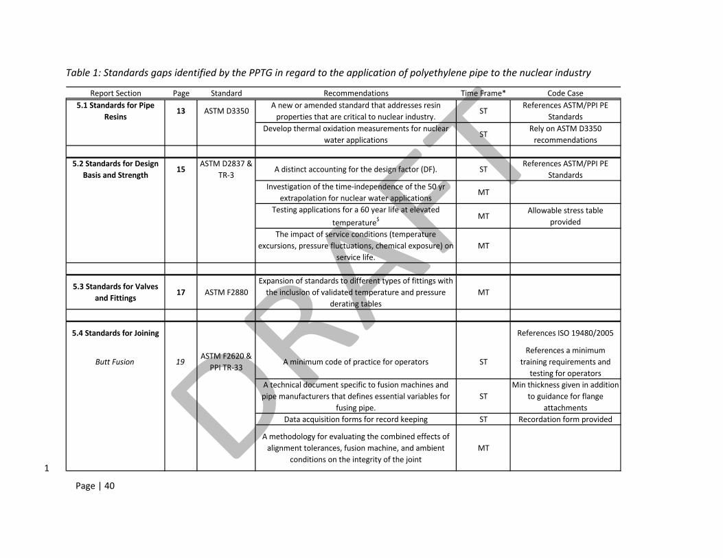
Page | 40
Table 1: Standards gaps identified by the PPTG in regard to the application of polyethylene pipe to the nuclear industry
Report Section Page Standard Recommendations Time Frame* Code Case5.1 Standards for Pipe
Resins13 ASTM D3350
A new or amended standard that addresses resin properties that are critical to nuclear industry.
STReferences ASTM/PPI PE
StandardsDevelop thermal oxidation measurements for nuclear
water applicationsST
Rely on ASTM D3350 recommendations
5.2 Standards for Design Basis and Strength
15ASTM D2837 &
TR‐3A distinct accounting for the design factor (DF). ST
References ASTM/PPI PE Standards
Investigation of the time‐independence of the 50 yr extrapolation for nuclear water applications
MT
Testing applications for a 60 year life at elevated
temperature$MT
Allowable stress table provided
The impact of service conditions (temperature excursions, pressure fluctuations, chemical exposure) on
service life.MT
5.3 Standards for Valves and Fittings
17 ASTM F2880Expansion of standards to different types of fittings with the inclusion of validated temperature and pressure
derating tablesMT
5.4 Standards for Joining References ISO 19480/2005
Butt Fusion 19ASTM F2620 &
PPI TR‐33A minimum code of practice for operators ST
References a minimum training requirements and
testing for operatorsA technical document specific to fusion machines and pipe manufacturers that defines essential variables for
fusing pipe.ST
Min thickness given in addition to guidance for flange
attachmentsData acquisition forms for record keeping ST Recordation form provided
A methodology for evaluating the combined effects of alignment tolerances, fusion machine, and ambient
conditions on the integrity of the joint MT
1
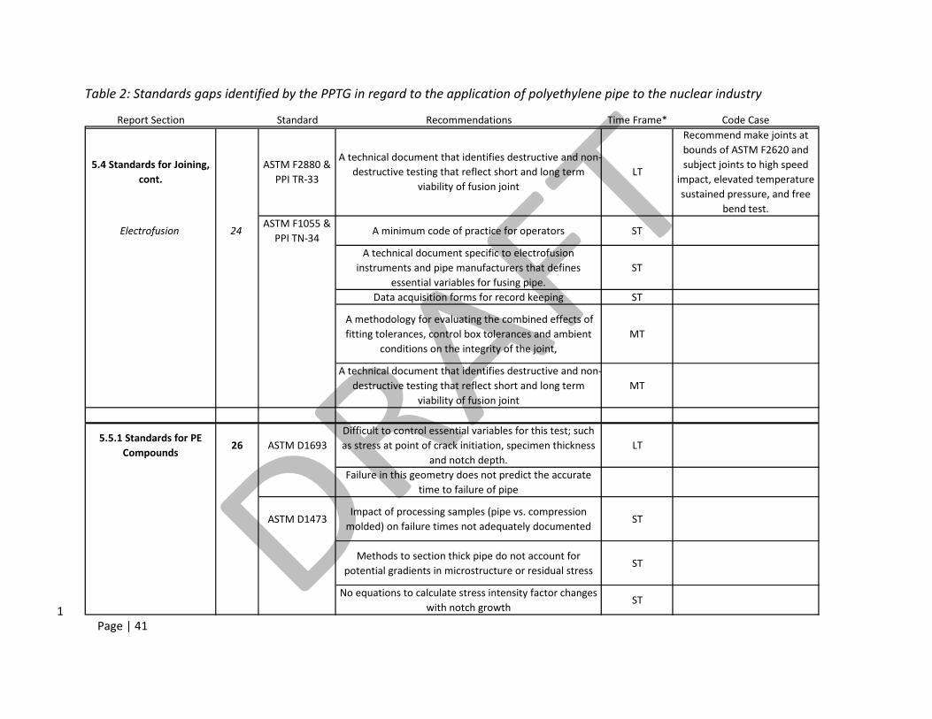
Page | 41
Table 2: Standards gaps identified by the PPTG in regard to the application of polyethylene pipe to the nuclear industry
Report Section Standard Recommendations Time Frame* Code Case
5.4 Standards for Joining, cont.
ASTM F2880 & PPI TR‐33
A technical document that identifies destructive and non‐destructive testing that reflect short and long term
viability of fusion jointLT
Recommend make joints at bounds of ASTM F2620 and subject joints to high speed
impact, elevated temperature sustained pressure, and free
bend test.
Electrofusion 24ASTM F1055 &
PPI TN‐34A minimum code of practice for operators ST
A technical document specific to electrofusion instruments and pipe manufacturers that defines
essential variables for fusing pipe.ST
Data acquisition forms for record keeping ST
A methodology for evaluating the combined effects of fitting tolerances, control box tolerances and ambient
conditions on the integrity of the joint, MT
A technical document that identifies destructive and non‐destructive testing that reflect short and long term
viability of fusion jointMT
5.5.1 Standards for PE Compounds
26 ASTM D1693Difficult to control essential variables for this test; such as stress at point of crack initiation, specimen thickness
and notch depth.LT
Failure in this geometry does not predict the accurate time to failure of pipe
ASTM D1473Impact of processing samples (pipe vs. compression molded) on failure times not adequately documented
ST
Methods to section thick pipe do not account for potential gradients in microstructure or residual stress
ST
No equations to calculate stress intensity factor changes with notch growth
ST 1
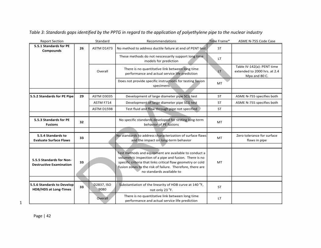
Page | 42
Table 3: Standards gaps identified by the PPTG in regard to the application of polyethylene pipe to the nuclear industry
Report Section Standard Recommendations Time Frame* ASME N‐755 Code Case5.5.1 Standards for PE
Compounds26 ASTM D1473 No method to address ductile failure at end of PENT test ST
These methods do not nescessarily support long time models for prediction
LT
OverallThere is no quantitative link between long time performance and actual service life prediction
LTTable IV‐142(a): PENT time extended to 2000 hrs. at 2.4
Mpa and 80 C.
Does not provide specific instructions for testing fusion specimens
MT
5.5.2 Standards for PE Pipe 29 ASTM D3035 Development of large diameter pipe SCG test ST ASME N‐755 specifies both
ASTM F714 Development of large diameter pipe SCG test ST ASME N‐755 specifies both
ASTM D1598 Test fluid and flow through pipe not specified ST
5.5.3 Standards for PE Fusions
32No specific standards developed for testing long‐term
behavior of PE fusionsMT
5.5.4 Standards to Evaluate Surface Flaws
33No standards to address characterization of surface flaws
and the impact on long‐term behaviorMT
Zero tolerance for surface flaws in pipe
5.5.5 Standards for Non‐Destructive Examination
33
Test methods and equipment are available to conduct a volumetric inspection of a pipe and fusion. There is no specific criteria that links critical flaw geometry or cold fusion zones to the risk of failure. Therefore, there are
no standards available to
MT
5.5.6 Standards to Develop HDB/HDS at Long‐Times
33D2837, ISO
9080Substantiation of the linearity of HDB curve at 140 oF,
not only 23 oF.ST
OverallThere is no quantitative link between long time performance and actual service life prediction
LT 1
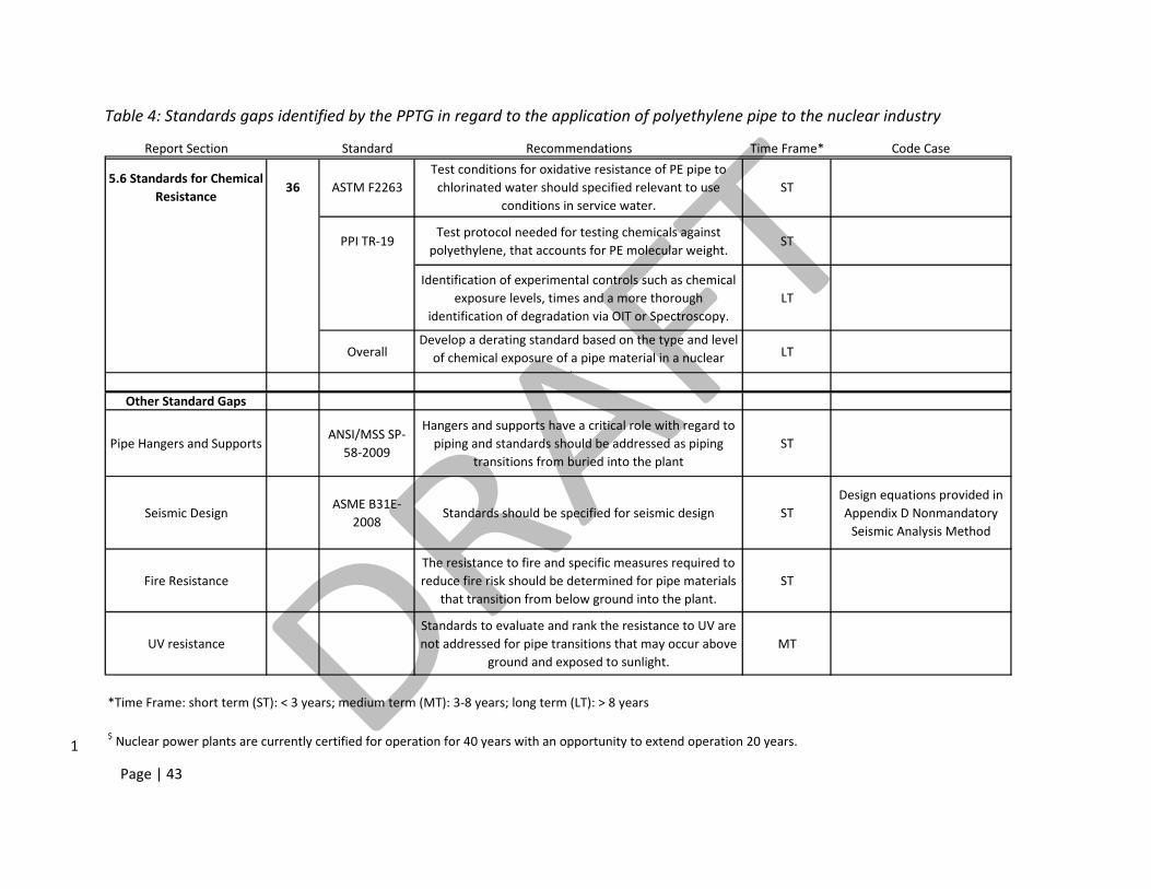
Page | 43
Table 4: Standards gaps identified by the PPTG in regard to the application of polyethylene pipe to the nuclear industry
Report Section Standard Recommendations Time Frame* Code Case
5.6 Standards for Chemical Resistance
36 ASTM F2263Test conditions for oxidative resistance of PE pipe to chlorinated water should specified relevant to use
conditions in service water.ST
PPI TR‐19Test protocol needed for testing chemicals against
polyethylene, that accounts for PE molecular weight. ST
Identification of experimental controls such as chemical exposure levels, times and a more thorough
identification of degradation via OIT or Spectroscopy.LT
OverallDevelop a derating standard based on the type and level of chemical exposure of a pipe material in a nuclear
l
LT
Other Standard Gaps
Pipe Hangers and SupportsANSI/MSS SP‐
58‐2009
Hangers and supports have a critical role with regard to piping and standards should be addressed as piping
transitions from buried into the plant ST
Seismic DesignASME B31E‐
2008Standards should be specified for seismic design ST
Design equations provided in Appendix D Nonmandatory Seismic Analysis Method
Fire ResistanceThe resistance to fire and specific measures required to reduce fire risk should be determined for pipe materials
that transition from below ground into the plant.ST
UV resistanceStandards to evaluate and rank the resistance to UV are not addressed for pipe transitions that may occur above
ground and exposed to sunlight.MT
*Time Frame: short term (ST): < 3 years; medium term (MT): 3‐8 years; long term (LT): > 8 years
$ Nuclear power plants are currently certified for operation for 40 years with an opportunity to extend operation 20 years.1
Page | 44
7 Roadmap for the Next Decade 1
2
In the previous section, gaps in the standards that pertain to the nuclear industry were identified. 3 Identifying these gaps is an important first step to developing the standards needed to facilitate the 4 incorporation of polymeric materials and composites for water transport in nuclear plants. It is 5 critical that a consensus path is developed to address those standards gaps such that SDO’s, 6 regulators, manufacturers, and operators can take action and close these gaps. The roadmap was 7 developed by the PPTG through evaluation of the standards gaps for nuclear piping. The breakdown 8 of topics follows the format of Section 5 and the time frame to fill the gap has been broken down as: 9
• Short Term – less than 3 years 10 • Medium Term – 3 years to 8 years 11 • Long Term – longer than 8 years 12
13
7.1 Short Term Gaps (< 3 yrs) 14
7.1.1 Standards for Pipe Resins 15
The main gap is the broad nature of ASTM D3350. The specifications for resins in the code case are 16 narrower than those given in this standard. Reducing the number of specifications to those required 17 for manufacture of piping specifically for nuclear applications will reduce the chance for confusion or 18 unnecessary testing. This is a gap that can be handled with the framework of an SDO such as ASTM in 19 conjunction with ASME. 20
7.1.2 Standards for Design Basis and Strength 21
ASME Code Case N‐755 utilizes a more conservative design factor (DF) of 0.5 compared to the design 22 factor of 0.63 used in the natural gas and water industry. This conservative approach is a consequence 23 of the cell classification for PE 4710 developed through ASTM D2837. If a higher DF is desired, a 24 technical basis will be required to support a new DF. This may be accomplished by tabulating the 25 factors that affect the design factor such as material variability, production variability, design 26 condition variability, etc. Reinhart14 has done this, but this type of support is often composed of 27 empirical experience rather than validated measurements conducted using standard test methods 28 required for the development of a technical basis. Another method is the development of a new cell 29 classification or design factor through the HDB/HDS standards that reflects the higher performance PE 30 materials for nuclear applications. 31
14 Reinhart, F; “Whence cometh the 2.0 design factor” letter from PPI (1994).
Page | 45
Both of the ASTM and ISO methods provide a conservative estimate of the long‐term hydrostatic 1 strength, which is then combined with a design factor. The HDB curve requires substantiation of 2 linearity by using elevated temperature testing to validate ductile failure extrapolation. HDPE has 3 been treated in the ASME Code Case N‐755 as if it will be exposed to an elevated temperature 4 throughout the design life, with the potential for temperature excursions. Currently, substantiation 5 to 50 yrs is not conducted at this elevated temperature. Substantiation of linearity should be 6 conducted as part of the development of a pipe material for nuclear operation. This could be quickly 7 accomplished through the current path of ASTM and PPI to incorporate a substantiation mechanism. 8
7.1.3 Standards for Joining 9
Butt fusion and electrofusion processes 10
These two joining methods have similar gaps, which may be addressed in the short term. In fact, 11 some of these are already addressed within the framework of ASME Code Case N‐755. A minimum 12 code of practice for operators is needed for training and certification of fusion machine operators. 13 This will reduce variability between fusions and operators. This code of practice should be developed 14 within the framework of ASME, the nuclear industry, and the NRC. 15
Similarly, a technical document specific to the type of pipe, SDR, pipe/resin manufacturer, and fusion 16 machine should be developed. This document would specify the essential variables for fusion and 17 provide traceability for why those variables were chosen. 18
Acquisition and storage of fusion data is critical for maintaining the system over the long term and 19 identifying trouble spots in the case of an accident. The ASME Code Case N‐755 specifies a data 20 acquisition sheet, but there is no single acquisition standard that to hold the required data 21 acquisition. Data acquisition should be formalized through the ASME, ASTM, and U.S. NRC process. 22
7.1.4 Standards for PE Compounds 23
Specific changes should be made when concerning samples generated for long time testing. These 24 include changes to ASTM D1473 which describe the impact of processing samples (pipe vs. 25 compression mold) on failure times, appropriate methods to section and test thick pipe to account for 26 residual stress or microstructure gradients, methods to account for changes in stress intensity with 27 crack growth in notch testing, and methods to account for or remove samples that exhibit ductile 28 failure at the end of the test. These gaps can be addressed through support of additional research to 29 address sample preparation questions. Calculations of stress intensity and ductile failure may be 30 handled within the ASME and ASTM framework. 31
7.1.5 Standards for PE Pipe 32
ASTM D3035 does not specify ASTM F1473, but it does specify ASTM D1598. ASME Code Case N‐755 33 requires both notch testing of PE resins and hydrostatic testing of piping. Referencing all testing 34 required for nuclear plant applications can improve efficiency of standards. 35
Page | 46
ASTM D1598 does not fully specify initial water chemistry or tracking of water chemistry throughout 1 exposure. In addition, the flow through pipe should be specified since this is an important parameter 2 for testing long‐term behavior of PE pipe. 3
7.1.6 Standards for NDE Testing of Volumetric Flaws 4
There are multiple techniques are available to measure the characteristics of volumetric flaws, but 5 additional research is needed to specify the critical dimensions of a volumetric flaw. These critical 6 dimensions should be related to the pressure and temperature the piping or fitting will experience 7 during the design life. The critical dimensions should be specified to reflect the risk of failure for the 8 pipe or fusion joint in both the short and long term strength. When the critical dimensions are 9 specified, pipe, fittings, and valves with standard flaws may be generated to benchmark NDE 10 techniques and provide a target resolution for these emerging methods. A standard evaluation 11 protocol should be developed in ASME to train personnel and evaluate/accept new non‐destructive 12 technologies. 13
7.1.7 Develop HDB/HDS at Long‐times 14
The HDB curve requires substantiation of linearity by using elevated temperature testing to find the 15 knee in the ductile failure curve. HDPE is treated in the code case as if it will be exposed to an 16 elevated temperature throughout the full design life. It has become apparent that this temperature 17 represents an extreme and brief excursion of operating parameters. There is survey data of plant 18 safety water operating conditions available from the Electric Power Research Institute (EPRI) that 19 indicates continuous use temperatures are closer to 100 °F. Currently, substantiation is not conducted 20 at this elevated temperature to determine the HDB for the current HDPE resin. Substantiation of 21 linearity in the ductile failure envelope at elevated temperature should be conducted as part of the 22 development of a pipe material for nuclear operation. This could be quickly accomplished through 23 the current path of ASTM and PPI to incorporate a substantiation mechanism based on the current 24 protocols of ASTM D2837 and TR‐33. 25
7.1.8 Standards for Chemical Resistance 26
ASTM F2263 should be modified to specify the exposure test conditions to measure the oxidative 27 resistance of PE pipe to chlorinated water and this should be linked to specific water conditions within 28 the nuclear plant. This may be handled in the ASME and ASTM process with plant water chemistry 29 data provided by the nuclear industry via EPRI. 30
ASTM F2263 should develop a test protocol that is specific to nuclear PE resins with specific test 31 procedures and methods. The current HDPE resin used in nuclear industry water systems is 32 sufficiently different from unimodal (MDPE and LDPE) and non‐nuclear bimodal resin materials that it 33 requires a specific test protocol. This gap may be addressed through the ASTM process with input 34 from resin manufacturers and PPI. 35
Page | 47
The American Petroleum Institute (API) addresses chemical resistance through the introduction of 1 classes of chemicals in standard API 17 TR2. The class is determined by a fit of the time to reach a 2 minimum dynamic toughness value at a specific temperature. Increasing the class number is 3 indicative of a more severe chemical. A system that ties pipe risk to severity of chemical exposure will 4 increase the efficiency of asset management systems. While the API standard can serve as a 5 foundation for a new standard, new research on the specific chemical risk to nuclear plant specific 6 chemicals is required. 7
ASTM D2837 develops the HDB/HDS curve utilizing water, many times de‐ionized The pure water 8 chemistry in this test can impact the failure time by reducing the oxidation of the pipe wall or altering 9 the diffusion rate of anti‐oxidant additives from the pipe wall. ASTM F2263 should provide a test 10 method to account for the combined effects of oxidative attack and accelerated failure in the 11 determination of the HDB/HDS curve. This gap should be addressed by further research to define a 12 suitable test method with a clear understanding of the test limits and error at the University or 13 Government Institute level. This test method would be incorporated into the standard and potentially 14 a chemical class system through the ASTM and ASME process. 15
7.1.9 Other Standards Gaps 16
Pipes Hangars and Supports 17
Buried pipe is expected to transition from a buried system to an above ground system within the 18 plant. Once the pipe is above ground, it must be supported through a system of hangars and 19 supports. This may also be the case for pipes that are within a buried trench and that could be 20 inspected from the outside (i.e. not covered with backfill). In addition, bracing systems should also be 21 considered in conjunction with hangers and supports; especially regarding seismic, wind, and dynamic 22 loading. The ANSI/MSS SP‐58‐2009 standard has been developed to address many of the design and 23 installation needs for polymeric and related piping infrastructure support, including water. MSS 24 should be encouraged to address any standard gaps within the next version of SP‐58, based on NRC 25 and/or nuclear industry needs for pipe hangars and supports. 26
Seismic Design 27
ASME Code Case N‐755 provides equations for Nonmandatory Seismic Analysis for pipe design in 28 Appendix D. Guidance for seismic design is provided in the ASME B31E‐2008 section code. A 29 standard for seismic design should be developed that reduces any redundancy and specifies the 30 differences between the needs of the nuclear industry and the ASME B31.1 code. This gap should be 31 addressed through the ASME, ASTM, U.S. NRC code approval process. If the performance of thick 32 section HDPE pipe is not sufficiently known, than research should be funded to develop validated 33 models that would guide standards development. EPRI has conducted seismic analysis of PE pipe 34
Page | 48
systems, for use in aboveground applications, to measure material properties relevant to seismic 1 design15. 2
Seismic design should also include bracing pipe for wind and seismic threats as pipe transitions into 3 the nuclear plant infrastructure. MSS SP‐127 Bracing for Piping Systems Seismic‐Wind‐Dynamic 4 Design, Selection, Application was first published in 2001 and has specific relevance to seismic, wind, 5 and other dynamic elements pertinent to piping systems and their stabilization within the nuclear 6 industry. This standard is currently being substantially revised and updated (revision expected 2012 7 time‐frame) and can be utilized in its own right, in tandem with, or complimentary with ASME B31.1. 8 MSS should be encouraged to address any standard gaps within the next version of SP‐127, based on 9 U.S. NRC and/or nuclear industry needs and process. 10
Fire Resistance 11
While the majority of buried HDPE pipe may reside underground, where the risk of fire is minimal, 12 sections that are above ground will be at risk of fire. Standards should be developed to determine the 13 fire resistance of HDPE materials, especially the design parameters in the event of a fire or explosion 14 within the plant. Standards should be developed to specify suitable fire resistant coatings for these 15 resin systems, in the event that large diameter HDPE pipe does not provide a sufficient safety factor 16 for fire fighting. EPRI has investigated the performance of polyethylene pipe protected by a fire‐17 resistance wrapping16 and subjected to fire conditions according to ASTM E11917 and hose stream 18 conditions of ASTM E222618. Finally, any additional coatings applied to the pipe must be tested 19 according to standards that address adhesion, flexibility, thermal conductivity, impact performance, 20 and fire performance. 21
7.2 Medium Term Gaps (3 ‐ 8 yrs) 22
7.2.1 Standards for Design Basis and Strength 23
The code case sets the design life at 50 yrs. Under certain design conditions, the pipe could last 24 longer than 50 yrs. A new standard or documentation should be developed to determine the time‐25 independence of performance up to and beyond 50 yrs at the use conditions. This would be in 26 addition to substantiation at elevated temperature. One challenge that remains is the availability of 27 test methods that measure long term failure in a reasonable test time. An example of a method to 28 address this challenge is the recent development of a cracked round bar (CRB) fatigue or creep tests 29 for the measurement of slow crack growth (SCG) at elevated temperature. This gap should be 30
15 “Seismic properties for high‐density polyethylene pipe for use in above‐ground applications” Product ID: 1021095; EPRI (2011) 16 “Fire Testing of High‐Density Polyethylene Pipe” Product ID: 1023004; EPRI (2011) 17 ASTM E119‐12 “Standard test methods for fire tests of building construction materials” ASTM International, West Conshohocken, PA 2012 18 ASTM E2226‐11 “Standard practice for application of hose stream” ASTM International, West Conshohocken, PA 2011
Page | 49
addressed by leveraging the most recent research available on SCG measurement in PE pipe. 1 Validation of any selected test method should be conducted between Industry and recognized 2 independent laboratories with results available for the U.S. NRC. 3
One remaining challenge is the expectation of continuous elevated temperature service over the 60 yr 4 service time of a nuclear power plant. These systems are utilized intermittently, which means design 5 for continuous elevated temperature could be an overestimate of failure time. A step to refine failure 6 time is to measure the RPM coefficients and creep data for nuclear HDPE pipe resins. Other options 7 would include cyclic pressure testing of pipe. This data would be utilized to develop models that 8 predict pipe lifetime based on pressure and temperature excursions over the lifetime of the pipe. 9 New standards would need to be developed to address the use of these models or test methods. 10
7.2.2 Standards for Valves and Fittings 11
Standards should be expanded to include the design of additional fittings and valves. Any fitting and 12 valves standards should include validated temperature and pressure derating tables. The derating 13 factors should be referenced to test results available in the open literature. In addition, these 14 standards should account for the application of hybrid systems that include both polymer and metal 15 components. The standard should be addressed in the ASTM and ASME process, since many of the 16 basic design and derating procedures are available for the water and gas industry. 17
A standards gap remains in the measurement of SCG in fittings. The complex stress states in the 18 geometry of valves and fittings have the potential to accelerate SCG. Any standards developed for 19 valves and fittings should include the procedure to determine the long term HDB and HDS for the 20 fitting and valve. This gap should be addressed through further research to determine the critical 21 dimensions that accelerate SCG and these limits specified in the standard. The standard should be 22 developed in the ASME and ASTM process. 23
24
7.2.3 Standards for Joining 25
Butt fusion and electrofusion processes 26
These two joining methods have similar gaps, which may be addressed in the medium term. Current 27 standards subject joints to a multitude of stress states (tension, notch testing, and bend back testing) 28 and time scales (quasi‐static, hydrostatic, and impact) for performance testing. There are no 29 standards that address the effect of multiple stresses on joint strength. An example is the impact of 30 misalignment, fitting tolerances, and ambient conditions on joint performance in the short time and 31 long time. Standards should be developed that address combined effects on performance. Since the 32 combination of parameters is staggering, further materials research combined with perturbation 33 analysis is needed to define the fusion test method. This standard method would be developed in the 34 ASME and ASTM process. 35
Page | 50
As HDPE receives greater use within the nuclear plant infrastructure, the potential to transition from a 1 plastic pipe to a metal or other plastic pipe will increase. The community should be aware of 2 situations that would require coupling dissimilar materials and identify standards earlier rather than 3 later. MSS SP‐107 Transition Union Fittings for Joining Metal and Plastic Products is a withdrawn 4 standard that addresses some of these issues. This standard could be revisited based on NRC and/or 5 nuclear industry needs and process or provide material for another standard provided MSS is aware 6 of the need to revisit the standard. In addition, PPI TN‐36 General Guidelines for Connecting HDPE 7 Potable Water Pressure Pipes to Ductile Iron and PVC Piping systems covers flanged connectors, solid 8 iron sleeves, and bell adapters. 9
7.2.4 Standards for PE Compounds 10
The current standards do not specify how to test fusion specimens generated from resin materials for 11 SCG measurements. This includes machining specimens from pipe, inserting notches, and verifying 12 the location of failure within the fusion zone. ASTM D1473 should be updated to address fusion joint 13 preparation and testing. Measurements are needed to verify crack propagation within the interface 14 and not within the body of the pipe. This gap would require further research to measure the error 15 induced via test sample preparation and methods to verify that sample preparation (cutting, molding, 16 extrusion) does not influence results. ASTM D1473 would be updated through the ASME and ASTM 17 process. 18
7.2.5 Standards for PE Fusions 19
Research should be supported to develop a specific standard test method for PE fusions, especially 20 those used to generate fittings. There are techniques within the academic literature that show 21 promise to capture joint quality, but these need to be developed into a test standard. Short term 22 testing should be limited to those tests that test specific modes of failure or stress induced failures 23 (e.g. Mode I, Mode II, or mixed Modes) experienced by fusion joints during service. 24
7.2.6 Standards to Evaluate Surface Flaws 25
There are currently no standards to characterize surface flaws in pipe. Standard methods should be 26 developed to quantify flaw dimensions and train personnel to evaluate flaws in the field. The risk of 27 failure in both short term and long term should be identified for flaws based on geometry, location, 28 and piping service environment. This will require additional research to identify the most common 29 flaw geometries. Statistical models that allow operators to quantify the risk of failure will be needed 30 to assign a risk factor and guide repair/removal decisions to facilitate efficient plant asset 31 management. 32
7.2.7 Standards for Ultraviolet and Ionizing Radiation 33
HDPE pipe is often exposed to ultra‐violet radiation during shipping, while awaiting installation, and 34 transitioning from below ground. The intensity of radiation, time of exposure, and resin additives are 35 critical for minimizing damage. Standards should be adopted to verify the performance of HDPE 36
Page | 51
resins after prolonged exposure. This information has been available in the water and gas industry, 1 but results specific to nuclear industry HDPE should be compiled and evaluated to determine whether 2 more research is required to specify an accelerated UV exposure test. 3
Similarly, a standards gap exists concerning radiation exposure. The nuclear industry and regulators 4 should identify the potential radiation type and dosage range. While current implementation of PE is 5 not intended for exposure to damaging levels of radiation, a gap for verification of durability under 6 ionizing radiation exists. This information may be used to direct future research into standards 7 development. The ASME and NRC may address this gap. 8
7.3 Long‐term Gaps (> 8 years) 9
7.3.1 Standards for PE Compounds, PE Pipe, and PE Fusions 10
The significant long‐term standards challenge is the inability to incorporate data generated in long 11 time testing into predictive models. This leads to a standards gap where long time data must be 12 generated for each resin and potentially each application. For example, ASTM F1473 for PENT is not a 13 service life predictor. It is only an index test for PE compounds to rank one to another for this type is 14 slow crack growth performance. Granted, the industry has come to understand that in general a 15 higher PENT performance could lead to a longer potential service life, it is certainly not a “predictor” 16 of service life. The ASME Code Case N‐755 has provided that a PE compound must have a 2000 h 17 PENT performance, but there has been limited information to determine what this actually means to 18 the potential service life. This is a gap that should be studied. Even ASTM D2837 and ISO 9080 are 19 not lifetime prediction methods. They are long‐term hydrostatic strength determination methods. 20 These results can be used to assign a “lifetime” to the material, but it is erroneous and that 21 terminology should be avoided. This would be similar in metallic piping to identify the tensile 22 strength as the sole determination of lifetime – which is not true. The metallic materials’ ability to 23 withstand corrosion and fatigue are better indicators. The same is true for PE compounds. The HDB 24 is the strength and the allowable stress values are not considered time dependent. Other factors, 25 such as the ability of the material to shed localized stress intensifications, and the oxidative 26 environment should be included in estimates of a service “lifetime”. A standardized test to generate 27 long time data that supports predictive models for quantitative service life would close this gap. This 28 will require significant research to identify a quantitative lifetime prediction test and associated 29 predictive models. 30
7.3.2 Standards for Chemical Resistance 31
A standard gap exists for the derating of HDPE pipe performance based on exposure to degradative 32 chemicals. This includes both continuous exposure, cyclic exposure, and exposure at elevated 33 temperatures. This standard gap should be addressed through the identification of the specific 34 chemicals within the nuclear plant. The short term standard gap that addresses exposure limits and 35 test conditions would be utilized to formulate the derating system which would be introduced into 36 the ASTM standard for chemical resistance 37
Page | 52
7.3.3 Incorporation of New Pipe Materials 1
This standards evaluation report has focused on HDPE pipe applications. There are other classes of 2 materials used within the natural gas and oil industry that can provide additional capabilities to the 3 nuclear industry in high temperature and pressure applications. In order for the nuclear industry to 4 take advantage of these materials, each material will be subjected to the code case process. It is 5 critical that the lessons learned from ASME Code Case N‐755 are translated to a roadmap for bringing 6 new pipe materials online. This will allow the efficient collection and evaluation of current standards 7 and available data sets to organize technical basis documents before and during the code case 8 process. 9
8 Summary 10
The PPTG conducted a comprehensive review of standards related to PE piping for nuclear 11 applications. This review of standards identified gaps that could be filled within a reasonable time 12 frame. In some cases, the gaps require only a better specification of procedures to greatly increase 13 the relevance and quality of the existing standard. In other cases, a program to address gaps in the 14 current understanding of PE performance must be addressed through the development of new 15 materials science and measurements. The PPTG has provided guidelines to address standards gaps 16 and the increased performance requirements for nuclear piping. The implementation and 17 prioritization should be developed between operators, regulators, and SDO organizations. This is 18 especially true where the gaps are related to increasing material performance or acceptance 19 requirements rather than the development of a new standard. Increases in performance and 20 acceptance requirements are often explicitly stated within the code in order to maintain broad 21 applicability of standards. This can reduce efficiency since it requires maintenance of a significant 22 database of documents related to specification, design, and quality assurance/quality control. 23
While this standards review was focused on PE piping, the gaps identified should apply to other non‐24 metallic pipe materials and systems. The main lessons learned were that many of the questions 25 developed in a code case can be answered when validated technical data is available to the industry 26 and regulators concerning the specific materials, intended design specifications, and environmental 27 conditions. This technical data is crucial for the development of the technical basis for design and 28 supporting the development of code requirements. The best method to generate this data efficiently 29 and in a manner that is accepted by material manufacturers, operators, and regulators is through the 30 development of current and relevant standards. 31
32
33
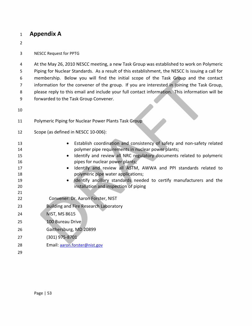
Page | 53
Appendix A 1
2
NESCC Request for PPTG 3
At the May 26, 2010 NESCC meeting, a new Task Group was established to work on Polymeric 4
Piping for Nuclear Standards. As a result of this establishment, the NESCC Is issuing a call for 5
membership. Below you will find the initial scope of the Task Group and the contact 6
information for the convener of the group. If you are interested in joining the Task Group, 7
please reply to this email and include your full contact information. This information will be 8
forwarded to the Task Group Convener. 9
10
Polymeric Piping for Nuclear Power Plants Task Group 11
Scope (as defined in NESCC 10‐006): 12
• Establish coordination and consistency of safety and non‐safety related 13 polymer pipe requirements in nuclear power plants; 14
• Identify and review all NRC regulatory documents related to polymeric 15 pipes for nuclear power plants; 16
• Identify and review all ASTM, AWWA and PPI standards related to 17 polymeric pipe water applications; 18
• Identify ancillary standards needed to certify manufacturers and the 19 installation and inspection of piping 20 21
Convener: Dr. Aaron Forster, NIST 22
Building and Fire Research Laboratory 23
NIST, MS 8615 24
100 Bureau Drive 25
Gaithersburg, MD 20899 26
(301) 975‐8701 27
Email: [email protected] 28
29
Page | 54
Appendix B 1
These following tables provide a summary of ASTM standards concerning material property and 2 performance characterization of various thermoplastic, thermoset, and composite materials that are 3 present in piping systems. The Non‐Metallic working group within Section III of ASME kindly provided 4 them to the PPTG for publication within this report. The PPTG would like to thank ASME for providing 5 this information. Missing standards or incomplete sections have been removed from this publication 6 in order to provide a complete table 7
8
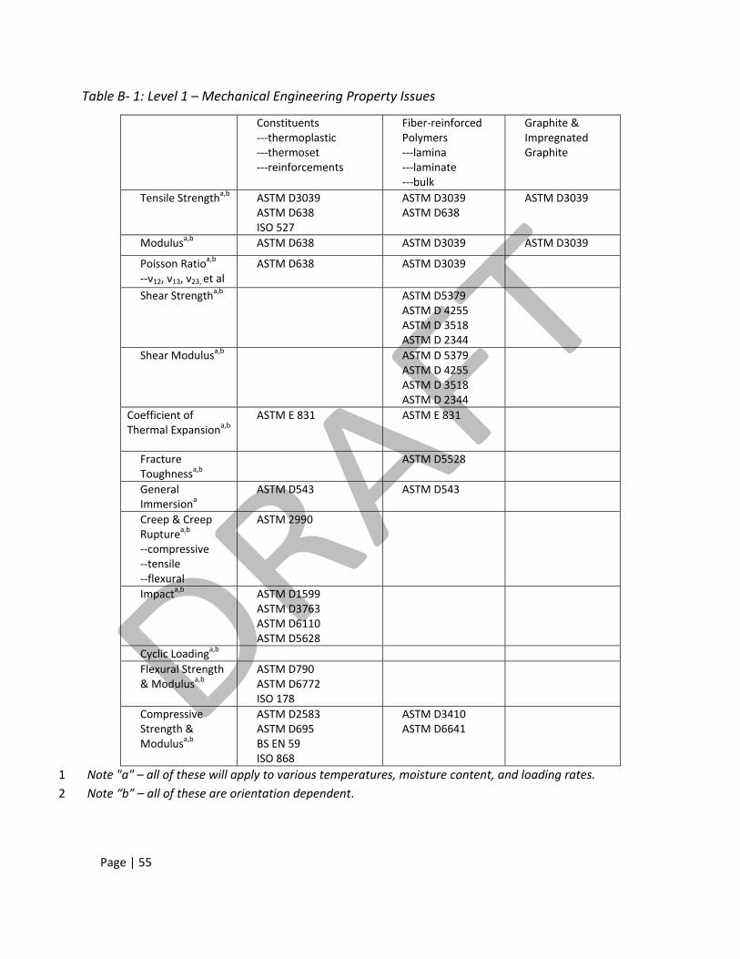
Page | 55
Table B‐ 1: Level 1 – Mechanical Engineering Property Issues
Constituents‐‐‐thermoplastic ‐‐‐thermoset ‐‐‐reinforcements
Fiber‐reinforced Polymers ‐‐‐lamina ‐‐‐laminate ‐‐‐bulk
Graphite & Impregnated Graphite
Tensile Strengtha,b ASTM D3039ASTM D638 ISO 527
ASTM D3039ASTM D638
ASTM D3039
Modulusa,b ASTM D638 ASTM D3039 ASTM D3039
Poisson Ratioa,b ‐‐ν12, ν13, ν23, et al
ASTM D638 ASTM D3039
Shear Strengtha,b ASTM D5379ASTM D 4255 ASTM D 3518 ASTM D 2344
Shear Modulusa,b ASTM D 5379ASTM D 4255 ASTM D 3518 ASTM D 2344
Coefficient of Thermal Expansiona,b
ASTM E 831 ASTM E 831
Fracture Toughnessa,b
ASTM D5528
General Immersiona
ASTM D543 ASTM D543
Creep & Creep Rupturea,b ‐‐compressive ‐‐tensile ‐‐flexural
ASTM 2990
Impacta,b
ASTM D1599ASTM D3763 ASTM D6110 ASTM D5628
Cyclic Loadinga,b Flexural Strength & Modulusa,b
ASTM D790ASTM D6772 ISO 178
Compressive Strength & Modulusa,b
ASTM D2583ASTM D695 BS EN 59 ISO 868
ASTM D3410ASTM D6641
Note "a" – all of these will apply to various temperatures, moisture content, and loading rates. 1 Note “b” – all of these are orientation dependent. 2
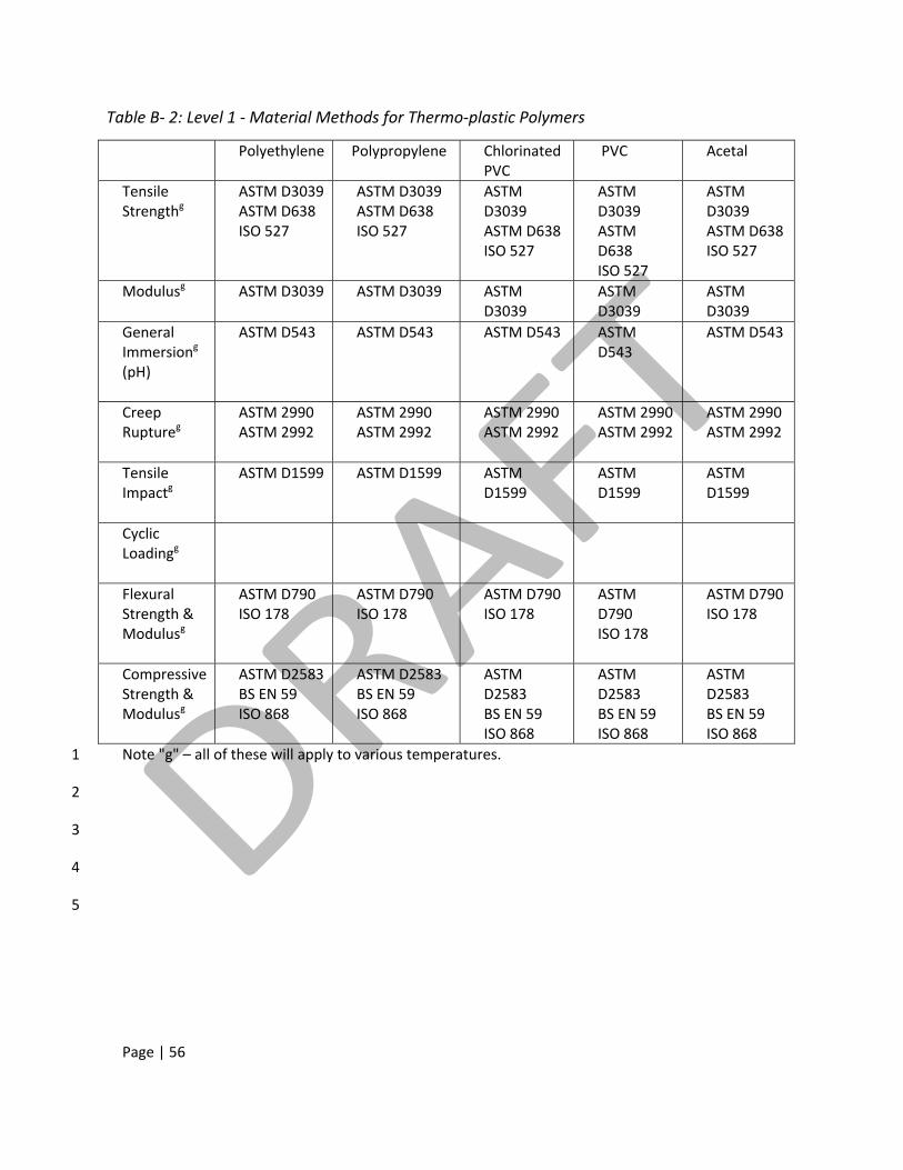
Page | 56
Table B‐ 2: Level 1 ‐ Material Methods for Thermo‐plastic Polymers
Polyethylene Polypropylene
Chlorinated PVC
PVC Acetal
Tensile Strengthg
ASTM D3039 ASTM D638 ISO 527
ASTM D3039 ASTM D638 ISO 527
ASTM D3039 ASTM D638 ISO 527
ASTM D3039 ASTM D638 ISO 527
ASTM D3039 ASTM D638 ISO 527
Modulusg
ASTM D3039 ASTM D3039 ASTM D3039
ASTM D3039
ASTM D3039
General Immersiong (pH)
ASTM D543 ASTM D543 ASTM D543 ASTM D543
ASTM D543
Creep Ruptureg
ASTM 2990 ASTM 2992
ASTM 2990 ASTM 2992
ASTM 2990 ASTM 2992
ASTM 2990 ASTM 2992
ASTM 2990 ASTM 2992
Tensile Impactg
ASTM D1599 ASTM D1599 ASTM D1599
ASTM D1599
ASTM D1599
Cyclic Loadingg
Flexural Strength & Modulusg
ASTM D790 ISO 178
ASTM D790 ISO 178
ASTM D790 ISO 178
ASTM D790 ISO 178
ASTM D790 ISO 178
Compressive Strength & Modulusg
ASTM D2583 BS EN 59 ISO 868
ASTM D2583 BS EN 59 ISO 868
ASTM D2583 BS EN 59 ISO 868
ASTM D2583 BS EN 59 ISO 868
ASTM D2583 BS EN 59 ISO 868
Note "g" – all of these will apply to various temperatures. 1
2
3
4
5
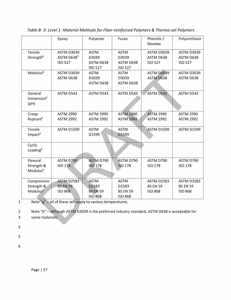
Page | 57
Table B‐ 3: Level 1‐ Material Methods for Fiber‐reinforced Polymers & Thermo‐set Polymers
Epoxy Polyester
Furan Phenolic / Novolac
Polyurethane
Tensile Strengthg
ASTM D3039 ASTM D638b ISO 527
ASTM D3039 ASTM D638 ISO 527
ASTM D3039 ASTM D638 ISO 527
ASTM D3039 ASTM D638 ISO 527
ASTM D3039 ASTM D638 ISO 527
Modulusg
ASTM D3039 ASTM D638
ASTM D3039 ASTM D638
ASTM D3039 ASTM D638
ASTM D3039 ASTM D638
ASTM D3039 ASTM D638
General Immersiong (pH)
ASTM D543 ASTM D543 ASTM D543 ASTM D543 ASTM D543
Creep Ruptureg
ASTM 2990 ASTM 2992
ASTM 2990 ASTM 2992
ASTM 2990 ASTM 2992
ASTM 2990 ASTM 2992
ASTM 2990 ASTM 2992
Tensile Impactg
ASTM D1599 ASTM D1599
ASTM D1599
ASTM D1599 ASTM D1599
Cyclic Loadingg
Flexural Strength & Modulusg
ASTM D790 ISO 178
ASTM D790 ISO 178
ASTM D790 ISO 178
ASTM D790 ISO 178
ASTM D790 ISO 178
Compressive Strength & Modulusg
ASTM D2583 BS EN 59 ISO 868
ASTM D2583 BS EN 59 ISO 868
ASTM D2583 BS EN 59 ISO 868
ASTM D2583 BS EN 59 ISO 868
ASTM D2583 BS EN 59 ISO 868
Note "g" – all of these will apply to various temperatures. 1
Note “b” – although ASTM D3039 is the preferred industry standard, ASTM D638 is acceptable for 2 some materials 3
4
5
6