Embed Size (px)
Citation preview
DISTRIBUTION STATEMENT A: Approved for public release; distribution is unlimited.
NONRESIDENTTRAININGCOURSE
SEPTEMBER 1998
Navy Electricity andElectronics Training Series
Module 10—Introduction to WavePropagation, Transmission Lines, andAntennas
NAVEDTRA 14182
DISTRIBUTION STATEMENT A: Approved for public release; distribution is unlimited.
Although the words “he,” “him,” and“his” are used sparingly in this course toenhance communication, they are notintended to be gender driven or to affront ordiscriminate against anyone.
i
PREFACE
By enrolling in this self-study course, you have demonstrated a desire to improve yourself and the Navy.Remember, however, this self-study course is only one part of the total Navy training program. Practicalexperience, schools, selected reading, and your desire to succeed are also necessary to successfully roundout a fully meaningful training program.
COURSE OVERVIEW : To introduce the student to the subject of Wave Propagation, TransmissionLines, and Antennas who needs such a background in accomplishing daily work and/or in preparing forfurther study.
THE COURSE: This self-study course is organized into subject matter areas, each containing learningobjectives to help you determine what you should learn along with text and illustrations to help youunderstand the information. The subject matter reflects day-to-day requirements and experiences ofpersonnel in the rating or skill area. It also reflects guidance provided by Enlisted Community Managers(ECMs) and other senior personnel, technical references, instructions, etc., and either the occupational ornaval standards, which are listed in theManual of Navy Enlisted Manpower Personnel Classificationsand Occupational Standards, NAVPERS 18068.
THE QUESTIONS: The questions that appear in this course are designed to help you understand thematerial in the text.
VALUE : In completing this course, you will improve your military and professional knowledge.Importantly, it can also help you study for the Navy-wide advancement in rate examination. If you arestudying and discover a reference in the text to another publication for further information, look it up.
1998 Edition Prepared byFCC(SW) R. Stephen Howard and CWO3 Harvey D. Vaughan
Published byNAVAL EDUCATION AND TRAINING
PROFESSIONAL DEVELOPMENTAND TECHNOLOGY CENTER
NAVSUP Logistics Tracking Number0504-LP-026-8350

ii
Sailor’s Creed
“ I am a United States Sailor.
I will support and defend theConstitution of the United States ofAmerica and I will obey the ordersof those appointed over me.
I represent the fighting spirit of theNavy and those who have gonebefore me to defend freedom anddemocracy around the world.
I proudly serve my country’s Navycombat team with honor, courageand commitment.
I am committed to excellence andthe fair treatment of all.”
iii
TABLE OF CONTENTS
CHAPTER PAGE
1. Wave Propagation .................................................................................................... 1-1
2. Radio Wave Propagation.......................................................................................... 2-1
3. Principles of Transmission Lines ............................................................................. 3-1
4. Antennas................................................................................................................... 4-1
APPENDIX
I. Glossary.................................................................................................................. AI-1
INDEX ......................................................................................................................... INDEX-1
iv
NAVY ELECTRICITY AND ELECTRONICS TRAININGSERIES
The Navy Electricity and Electronics Training Series (NEETS) was developed for use by personnel inmany electrical- and electronic-related Navy ratings. Written by, and with the advice of, seniortechnicians in these ratings, this series provides beginners with fundamental electrical and electronicconcepts through self-study. The presentation of this series is not oriented to any specific rating structure,but is divided into modules containing related information organized into traditional paths of instruction.
The series is designed to give small amounts of information that can be easily digested before advancingfurther into the more complex material. For a student just becoming acquainted with electricity orelectronics, it is highly recommended that the modules be studied in their suggested sequence. Whilethere is a listing of NEETS by module title, the following brief descriptions give a quick overview of howthe individual modules flow together.
Module 1, Introduction to Matter, Energy, and Direct Current, introduces the course with a short historyof electricity and electronics and proceeds into the characteristics of matter, energy, and direct current(dc). It also describes some of the general safety precautions and first-aid procedures that should becommon knowledge for a person working in the field of electricity. Related safety hints are locatedthroughout the rest of the series, as well.
Module 2, Introduction to Alternating Current and Transformers,is an introduction to alternating current(ac) and transformers, including basic ac theory and fundamentals of electromagnetism, inductance,capacitance, impedance, and transformers.
Module 3, Introduction to Circuit Protection, Control, and Measurement,encompasses circuit breakers,fuses, and current limiters used in circuit protection, as well as the theory and use of meters as electricalmeasuring devices.
Module 4, Introduction to Electrical Conductors, Wiring Techniques, and Schematic Reading,presentsconductor usage, insulation used as wire covering, splicing, termination of wiring, soldering, and readingelectrical wiring diagrams.
Module 5, Introduction to Generators and Motors,is an introduction to generators and motors, andcovers the uses of ac and dc generators and motors in the conversion of electrical and mechanicalenergies.
Module 6, Introduction to Electronic Emission, Tubes, and Power Supplies,ties the first five modulestogether in an introduction to vacuum tubes and vacuum-tube power supplies.
Module 7, Introduction to Solid-State Devices and Power Supplies,is similar to module 6, but it is inreference to solid-state devices.
Module 8, Introduction to Amplifiers,covers amplifiers.
Module 9, Introduction to Wave-Generation and Wave-Shaping Circuits,discusses wave generation andwave-shaping circuits.
Module 10, Introduction to Wave Propagation, Transmission Lines, and Antennas,presents thecharacteristics of wave propagation, transmission lines, and antennas.
v
Module 11,Microwave Principles,explains microwave oscillators, amplifiers, and waveguides.
Module 12,Modulation Principles,discusses the principles of modulation.
Module 13, Introduction to Number Systems and Logic Circuits,presents the fundamental concepts ofnumber systems, Boolean algebra, and logic circuits, all of which pertain to digital computers.
Module 14, Introduction to Microelectronics,covers microelectronics technology and miniature andmicrominiature circuit repair.
Module 15, Principles of Synchros, Servos, and Gyros,provides the basic principles, operations,functions, and applications of synchro, servo, and gyro mechanisms.
Module 16, Introduction to Test Equipment,is an introduction to some of the more commonly used testequipments and their applications.
Module 17, Radio-Frequency Communications Principles,presents the fundamentals of a radio-frequency communications system.
Module 18,Radar Principles,covers the fundamentals of a radar system.
Module 19, The Technician's Handbook,is a handy reference of commonly used general information,such as electrical and electronic formulas, color coding, and naval supply system data.
Module 20,Master Glossary,is the glossary of terms for the series.
Module 21,Test Methods and Practices,describes basic test methods and practices.
Module 22, Introduction to Digital Computers,is an introduction to digital computers.
Module 23,Magnetic Recording,is an introduction to the use and maintenance of magnetic recorders andthe concepts of recording on magnetic tape and disks.
Module 24, Introduction to Fiber Optics,is an introduction to fiber optics.
Embedded questions are inserted throughout each module, except for modules 19 and 20, which arereference books. If you have any difficulty in answering any of the questions, restudy the applicablesection.
Although an attempt has been made to use simple language, various technical words and phrases havenecessarily been included. Specific terms are defined in Module 20,Master Glossary.
Considerable emphasis has been placed on illustrations to provide a maximum amount of information. Insome instances, a knowledge of basic algebra may be required.
Assignments are provided for each module, with the exceptions of Module 19,The Technician'sHandbook; and Module 20,Master Glossary. Course descriptions and ordering information are inNAVEDTRA 12061,Catalog of Nonresident Training Courses.
vi
Throughout the text of this course and while using technical manuals associated with the equipment youwill be working on, you will find the below notations at the end of some paragraphs. The notations areused to emphasize that safety hazards exist and care must be taken or observed.
WARNING
AN OPERATING PROCEDURE, PRACTICE, OR CONDITION, ETC., WHICH MAYRESULT IN INJURY OR DEATH IF NOT CAREFULLY OBSERVED ORFOLLOWED.
CAUTION
AN OPERATING PROCEDURE, PRACTICE, OR CONDITION, ETC., WHICH MAYRESULT IN DAMAGE TO EQUIPMENT IF NOT CAREFULLY OBSERVED ORFOLLOWED.
NOTE
An operating procedure, practice, or condition, etc., which is essential to emphasize.
vii
INSTRUCTIONS FOR TAKING THE COURSE
ASSIGNMENTS
The text pages that you are to study are listed atthe beginning of each assignment. Study thesepages carefully before attempting to answer thequestions. Pay close attention to tables andillustrations and read the learning objectives.The learning objectives state what you should beable to do after studying the material. Answeringthe questions correctly helps you accomplish theobjectives.
SELECTING YOUR ANSWERS
Read each question carefully, then select theBEST answer. You may refer freely to the text.The answers must be the result of your ownwork and decisions. You are prohibited fromreferring to or copying the answers of others andfrom giving answers to anyone else taking thecourse.
SUBMITTING YOUR ASSIGNMENTS
To have your assignments graded, you must beenrolled in the course with the NonresidentTraining Course Administration Branch at theNaval Education and Training ProfessionalDevelopment and Technology Center(NETPDTC). Following enrollment, there aretwo ways of having your assignments graded:(1) use the Internet to submit your assignmentsas you complete them, or (2) send all theassignments at one time by mail to NETPDTC.
Grading on the Internet: Advantages toInternet grading are:
• you may submit your answers as soon asyou complete an assignment, and
• you get your results faster; usually by thenext working day (approximately 24 hours).
In addition to receiving grade results for eachassignment, you will receive course completionconfirmation once you have completed all the
assignments. To submit your assignmentanswers via the Internet, go to:
http://courses.cnet.navy.mil
Grading by Mail: When you submit answersheets by mail, send all of your assignments atone time. Do NOT submit individual answersheets for grading. Mail all of your assignmentsin an envelope, which you either provideyourself or obtain from your nearest EducationalServices Officer (ESO). Submit answer sheetsto:
COMMANDING OFFICERNETPDTC N3316490 SAUFLEY FIELD ROADPENSACOLA FL 32559-5000
Answer Sheets: All courses include one“scannable” answer sheet for each assignment.These answer sheets are preprinted with yourSSN, name, assignment number, and coursenumber. Explanations for completing the answersheets are on the answer sheet.
Do not use answer sheet reproductions:Useonly the original answer sheets that weprovide—reproductions will not work with ourscanning equipment and cannot be processed.
Follow the instructions for marking youranswers on the answer sheet. Be sure that blocks1, 2, and 3 are filled in correctly. Thisinformation is necessary for your course to beproperly processed and for you to receive creditfor your work.
COMPLETION TIME
Courses must be completed within 12 monthsfrom the date of enrollment. This includes timerequired to resubmit failed assignments.
viii
PASS/FAIL ASSIGNMENT PROCEDURES
If your overall course score is 3.2 or higher, youwill pass the course and will not be required toresubmit assignments. Once your assignmentshave been graded you will receive coursecompletion confirmation.
If you receive less than a 3.2 on any assignmentand your overall course score is below 3.2, youwill be given the opportunity to resubmit failedassignments. You may resubmit failedassignments only once. Internet students willreceive notification when they have failed anassignment--they may then resubmit failedassignments on the web site. Internet studentsmay view and print results for failedassignments from the web site. Students whosubmit by mail will receive a failing result letterand a new answer sheet for resubmission of eachfailed assignment.
COMPLETION CONFIRMATION
After successfully completing this course, youwill receive a letter of completion.
ERRATA
Errata are used to correct minor errors or deleteobsolete information in a course. Errata mayalso be used to provide instructions to thestudent. If a course has an errata, it will beincluded as the first page(s) after the front cover.Errata for all courses can be accessed andviewed/downloaded at:
http://www.advancement.cnet.navy.mil
STUDENT FEEDBACK QUESTIONS
We value your suggestions, questions, andcriticisms on our courses. If you would like tocommunicate with us regarding this course, weencourage you, if possible, to use e-mail. If youwrite or fax, please use a copy of the StudentComment form that follows this page.
For subject matter questions:
E-mail: [email protected]: Comm: (850) 452-1001, ext. 1728
DSN: 922-1001, ext. 1728FAX: (850) 452-1370(Do not fax answer sheets.)
Address: COMMANDING OFFICERNETPDTC N3156490 SAUFLEY FIELD ROADPENSACOLA FL 32509-5237
For enrollment, shipping, grading, orcompletion letter questions
E-mail: [email protected]: Toll Free: 877-264-8583
Comm: (850) 452-1511/1181/1859DSN: 922-1511/1181/1859FAX: (850) 452-1370(Do not fax answer sheets.)
Address: COMMANDING OFFICERNETPDTC N3316490 SAUFLEY FIELD ROADPENSACOLA FL 32559-5000
NAVAL RESERVE RETIREMENT CREDIT
If you are a member of the Naval Reserve, youwill receive retirement points if you areauthorized to receive them under currentdirectives governing retirement of NavalReserve personnel. For Naval Reserveretirement, this course is evaluated at 6 points.(Refer to Administrative Procedures for NavalReservists on Inactive Duty,BUPERSINST1001.39, for more information about retirementpoints.)
ix
Student Comments
Course Title:NEETS Module 10Introduction to Wave Propagation, Transmission Lines, and Antennas
NAVEDTRA: 14182 Date:
We need some information about you:
Rate/Rank and Name: SSN: Command/Unit
Street Address: City: State/FPO: Zip
Your comments, suggestions, etc.:
Privacy Act Statement: Under authority of Title 5, USC 301, information regarding your military status isrequested in processing your comments and in preparing a reply. This information will not be divulged withoutwritten authorization to anyone other than those within DOD for official use in determining performance.
NETPDTC 1550/41 (Rev 4-00)

1-1
CHAPTER 1
WAVE PROPAGATION
LEARNING OBJECTIVES
Learning objectives are stated at the beginning of each chapter. These learning objectives serve as apreview of the information you are expected to learn in the chapter. The comprehensive check questionsare based on the objectives. By successfully completing the NRTC, you indicate that you have met theobjectives and have learned the information. The learning objectives are listed below.
Upon completion of this chapter, you should be able to:
1. State what wave motion is, define the terms reflection, refraction, and diffraction, and describe theDoppler effect.
2. State what sound waves are and define a propagating medium.
3. List and define terms as applied to sound waves, such as cycle, frequency, wavelength, andvelocity.
4. List the three requirements for sound.
5. Define pitch, intensity, loudness, and quality and their application to sound waves.
6. State the acoustical effects that echoes, reverberation, resonance, and noise have on sound waves.
7. Define light waves and list their characteristics.
8. List the various colors of light and define the terms reflection, refraction, diffusion, and absorptionas applied to light waves.
9. State the difference between sound waves and light waves.
10. State the electromagnetic wave theory and list the components of the electromagnetic wave.
INTRODUCTION TO WAVE PROPAGATION
Of the many technical subjects that naval personnel are expected to know, probably the one leastsusceptible to change is the theory of wave propagation. The basic principles that enable waves to bepropagated (transmitted) through space are the same today as they were 70 years ago. One would think,then, that a thorough understanding of these principles is a relatively simple task. For the electricalengineer or the individual with a natural curiosity for the unknown, it is indeed a simple task. Mosttechnicians, however, tend to view wave propagation as something complex and confusing, and wouldjust as soon see this chapter completely disappear from training manuals. This attitude undoubtedly stemsfrom the fact that wave propagation is an invisible force that cannot be detected by the sense of sight ortouch. Understanding wave propagation requires the use of the imagination to visualize the associatedconcepts and how they are used in practical application. This manual was developed to help you visualize
1-2
and understand those concepts. Through ample use of illustrations and a step-by-step transition from thesimple to the complex, we will help you develop a better understanding of wave propagation. In thischapter, we will discuss propagation theory on an introductory level, without going into the technicaldetails that concern the engineer. However, you must still use thought and imagination to understand thenew ideas and concepts as they are presented.
To understand radio wave propagation, you must first learn what wave propagation is and some ofthe basic physics or properties that affect propagation. Many of these properties are common everydayoccurrences, with which you are already familiar.
WHAT IS PROPAGATION?
Early man was quick to recognize the need to communicate beyond the range of the human voice. Tosatisfy this need, he developed alternate methods of communication, such as hand gestures, beating on ahollow log, and smoke signals. Although these methods were effective, they were still greatly limited inrange. Eventually, the range limitations were overcome by the development of courier and postal systems;but there was then a problem of speed. For centuries the time required for the delivery of a messagedepended on the speed of a horse.
During the latter part of the 19th century, both distance and time limitations were largely overcome.The invention of the telegraph made possible instantaneous communication over long wires. Then a shorttime later, man discovered how to transmit messages in the form of RADIO WAVES.
As you will learn in this chapter, radio waves are propagated. PROPAGATION means "movementthrough a medium." This is most easily illustrated by light rays. When a light is turned on in a darkenedroom, light rays travel from the light bulb throughout the room. When a flashlight is turned on, light raysalso radiate from its bulb, but are focused into a narrow beam. You can use these examples to picture howradio waves propagate. Like the light in the room, radio waves may spread out in all directions. They canalso be focused (concentrated) like the flashlight, depending upon the need. Radio waves are a form ofradiant energy, similar to light and heat. Although they can neither be seen nor felt, their presence can bedetected through the use of sensitive measuring devices. The speed at which both forms of waves travel isthe same; they both travel at the speed of light.
You may wonder why you can see light but not radio waves, which consist of the same form ofenergy as light. The reason is that you can only "see" what your eyes can detect. Your eyes can detectradiant energy only within a fixed range of frequencies. Since the frequencies of radio waves are belowthe frequencies your eyes can detect, you cannot see radio waves.
The theory of wave propagation that we discuss in this module applies to Navy electronic equipment,such as radar, navigation, detection, and communication equipment. We will not discuss these individualsystems in this module, but we will explain them in future modules.
Q1. What is propagation?
PRINCIPLES OF WAVE MOTION
All things on the earth—on the land, or in the water—are showered continually with waves ofenergy. Some of these waves stimulate our senses and can be seen, felt, or heard. For instance, we can seelight, hear sound, and feel heat. However, there are some waves that do not stimulate our senses. For
1-3
example, radio waves, such as those received by our portable radio or television sets, cannot be seen,heard, or felt. A device must be used to convert radio waves into light (TV pictures) and sound (audio) forus to sense them.
A WAVE can be defined as a DISTURBANCE (sound, light, radio waves) that moves through aMEDIUM (air, water, vacuum). To help you understand what is meant by "a disturbance which movesthrough a medium," picture the following illustration. You are standing in the middle of a wheat field. Asthe wind blows across the field toward you, you can see the wheat stalks bending and rising as the forceof the wind moves into and across them. The wheat appears to be moving toward you, but it isn’t. Instead,the stalks are actually moving back and forth. We can then say that the "medium" in this illustration is thewheat and the "disturbance" is the wind moving the stalks of wheat.
WAVE MOTION can be defined as a recurring disturbance advancing through space with or withoutthe use of a physical medium. Wave motion, therefore, is a means of moving or transferring energy fromone point to another point. For example, when sound waves strike a microphone, sound energy isconverted into electrical energy. When light waves strike a phototransistor or radio waves strike anantenna, they are likewise converted into electrical energy. Therefore, sound, light, and radio waves areall forms of energy that are moved by wave motion. We will discuss sound waves, light waves, and radiowaves later.
Q2. How is a wave defined as it applies to wave propagation?
Q3. What is wave motion?
Q4. What are some examples of wave motion?
WAVE MOTION IN WATER
A type of wave motion familiar to almost everyone is the movement of waves in water. We willexplain these waves first to help you understand wave motion and the terms used to describe it.
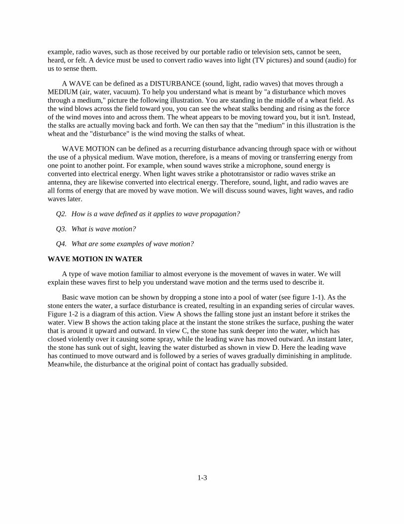
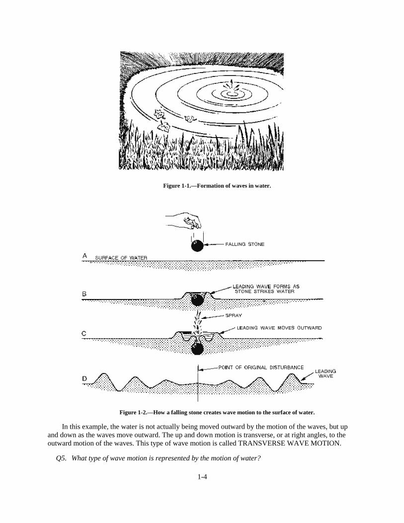
Basic wave motion can be shown by dropping a stone into a pool of water (see figure 1-1). As thestone enters the water, a surface disturbance is created, resulting in an expanding series of circular waves.Figure 1-2 is a diagram of this action. View A shows the falling stone just an instant before it strikes thewater. View B shows the action taking place at the instant the stone strikes the surface, pushing the waterthat is around it upward and outward. In view C, the stone has sunk deeper into the water, which hasclosed violently over it causing some spray, while the leading wave has moved outward. An instant later,the stone has sunk out of sight, leaving the water disturbed as shown in view D. Here the leading wavehas continued to move outward and is followed by a series of waves gradually diminishing in amplitude.Meanwhile, the disturbance at the original point of contact has gradually subsided.
1-4
Figure 1-1.—Formation of waves in water.
Figure 1-2.—How a falling stone creates wave motion to the surface of water.
In this example, the water is not actually being moved outward by the motion of the waves, but upand down as the waves move outward. The up and down motion is transverse, or at right angles, to theoutward motion of the waves. This type of wave motion is called TRANSVERSE WAVE MOTION.
Q5. What type of wave motion is represented by the motion of water?
1-5
TRANSVERSE WAVES
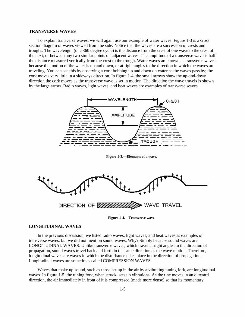
To explain transverse waves, we will again use our example of water waves. Figure 1-3 is a crosssection diagram of waves viewed from the side. Notice that the waves are a succession of crests andtroughs. The wavelength (one 360 degree cycle) is the distance from the crest of one wave to the crest ofthe next, or between any two similar points on adjacent waves. The amplitude of a transverse wave is halfthe distance measured vertically from the crest to the trough. Water waves are known as transverse wavesbecause the motion of the water is up and down, or at right angles to the direction in which the waves aretraveling. You can see this by observing a cork bobbing up and down on water as the waves pass by; thecork moves very little in a sideways direction. In figure 1-4, the small arrows show the up-and-downdirection the cork moves as the transverse wave is set in motion. The direction the wave travels is shownby the large arrow. Radio waves, light waves, and heat waves are examples of transverse waves.
Figure 1-3.—Elements of a wave.
Figure 1-4.—Transverse wave.
LONGITUDINAL WAVES
In the previous discussion, we listed radio waves, light waves, and heat waves as examples oftransverse waves, but we did not mention sound waves. Why? Simply because sound waves areLONGITUDINAL WAVES. Unlike transverse waves, which travel at right angles to the direction ofpropagation, sound waves travel back and forth in the same direction as the wave motion. Therefore,longitudinal waves are waves in which the disturbance takes place in the direction of propagation.Longitudinal waves are sometimes called COMPRESSION WAVES.
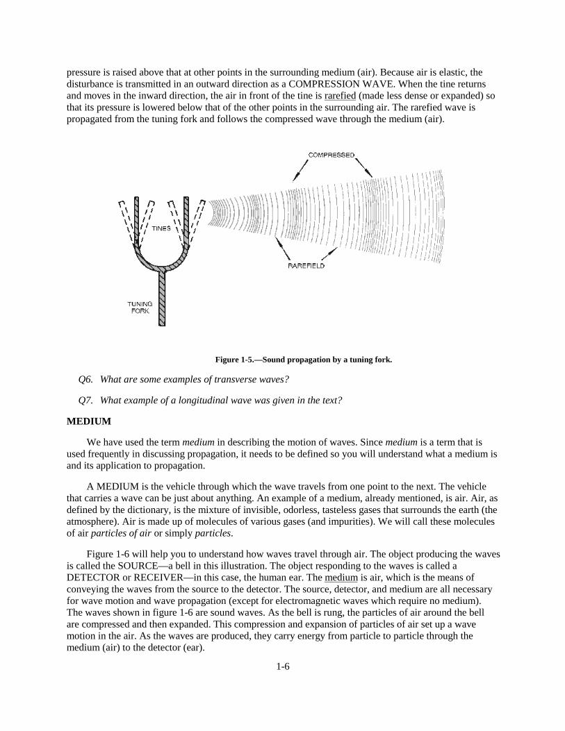
Waves that make up sound, such as those set up in the air by a vibrating tuning fork, are longitudinalwaves. In figure 1-5, the tuning fork, when struck, sets up vibrations. As the tine moves in an outwarddirection, the air immediately in front of it is compressed (made more dense) so that its momentary
1-6
pressure is raised above that at other points in the surrounding medium (air). Because air is elastic, thedisturbance is transmitted in an outward direction as a COMPRESSION WAVE. When the tine returnsand moves in the inward direction, the air in front of the tine is rarefied (made less dense or expanded) sothat its pressure is lowered below that of the other points in the surrounding air. The rarefied wave ispropagated from the tuning fork and follows the compressed wave through the medium (air).
Figure 1-5.—Sound propagation by a tuning fork.
Q6. What are some examples of transverse waves?
Q7. What example of a longitudinal wave was given in the text?
MEDIUM
We have used the term medium in describing the motion of waves. Since medium is a term that isused frequently in discussing propagation, it needs to be defined so you will understand what a medium isand its application to propagation.
A MEDIUM is the vehicle through which the wave travels from one point to the next. The vehiclethat carries a wave can be just about anything. An example of a medium, already mentioned, is air. Air, asdefined by the dictionary, is the mixture of invisible, odorless, tasteless gases that surrounds the earth (theatmosphere). Air is made up of molecules of various gases (and impurities). We will call these moleculesof air particles of air or simply particles.
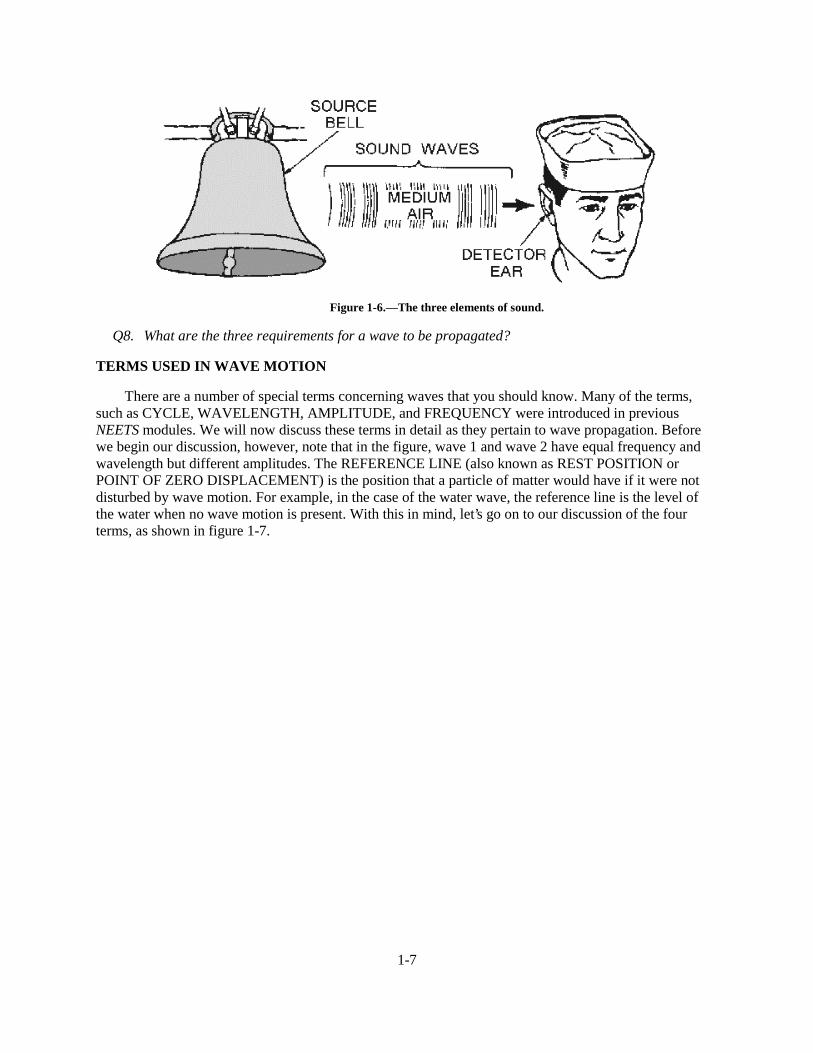
Figure 1-6 will help you to understand how waves travel through air. The object producing the wavesis called the SOURCE—a bell in this illustration. The object responding to the waves is called aDETECTOR or RECEIVER—in this case, the human ear. The medium is air, which is the means ofconveying the waves from the source to the detector. The source, detector, and medium are all necessaryfor wave motion and wave propagation (except for electromagnetic waves which require no medium).The waves shown in figure 1-6 are sound waves. As the bell is rung, the particles of air around the bellare compressed and then expanded. This compression and expansion of particles of air set up a wavemotion in the air. As the waves are produced, they carry energy from particle to particle through themedium (air) to the detector (ear).
1-7
Figure 1-6.—The three elements of sound.
Q8. What are the three requirements for a wave to be propagated?
TERMS USED IN WAVE MOTION
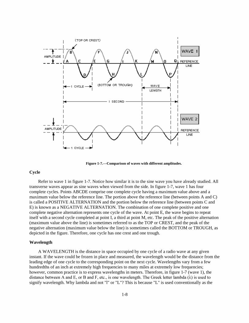
There are a number of special terms concerning waves that you should know. Many of the terms,such as CYCLE, WAVELENGTH, AMPLITUDE, and FREQUENCY were introduced in previousNEETS modules. We will now discuss these terms in detail as they pertain to wave propagation. Beforewe begin our discussion, however, note that in the figure, wave 1 and wave 2 have equal frequency andwavelength but different amplitudes. The REFERENCE LINE (also known as REST POSITION orPOINT OF ZERO DISPLACEMENT) is the position that a particle of matter would have if it were notdisturbed by wave motion. For example, in the case of the water wave, the reference line is the level ofthe water when no wave motion is present. With this in mind, let’s go on to our discussion of the fourterms, as shown in figure 1-7.
1-8
Figure 1-7.—Comparison of waves with different amplitudes.
Cycle
Refer to wave 1 in figure 1-7. Notice how similar it is to the sine wave you have already studied. Alltransverse waves appear as sine waves when viewed from the side. In figure 1-7, wave 1 has fourcomplete cycles. Points ABCDE comprise one complete cycle having a maximum value above and amaximum value below the reference line. The portion above the reference line (between points A and C)is called a POSITIVE ALTERNATION and the portion below the reference line (between points C andE) is known as a NEGATIVE ALTERNATION. The combination of one complete positive and onecomplete negative alternation represents one cycle of the wave. At point E, the wave begins to repeatitself with a second cycle completed at point I, a third at point M, etc. The peak of the positive alternation(maximum value above the line) is sometimes referred to as the TOP or CREST, and the peak of thenegative alternation (maximum value below the line) is sometimes called the BOTTOM or TROUGH, asdepicted in the figure. Therefore, one cycle has one crest and one trough.
Wavelength
A WAVELENGTH is the distance in space occupied by one cycle of a radio wave at any giveninstant. If the wave could be frozen in place and measured, the wavelength would be the distance from theleading edge of one cycle to the corresponding point on the next cycle. Wavelengths vary from a fewhundredths of an inch at extremely high frequencies to many miles at extremely low frequencies;however, common practice is to express wavelengths in meters. Therefore, in figure 1-7 (wave 1), theGLVWDQFH�EHWZHHQ�$�DQG�(��RU�%�DQG�)��HWF���LV�RQH�ZDYHOHQJWK��7KH�*UHHN�OHWWHU�ODPEGD�� ��LV�XVHG�WRsignify wavelength. Why lambda and not "l" or "L"? This is because "L" is used conventionally as the
1-9
V\PERO�IRU�LQGXFWDQFH��DQG��O��LV�XVHG�IRU�GLPHQVLRQDO�OHQJWK��WKHUHIRUH�� ; is used to indicate the lengthof waves.
Amplitude
Two waves may have the same wavelength, but the crest of one may rise higher above the referenceline than the crest of the other. Compare wave 1 and wave 2 of figure 1-7 again. The height of a wavecrest above the reference line is called the AMPLITUDE of the wave. The amplitude of a wave gives arelative indication of the amount of energy the wave transmits. A continuous series of waves, such as Athrough Q, having the same amplitude and wavelength, is called a train of waves or WAVE TRAIN.
Frequency and Time
Time is an important factor in wave studies. When a wave train passes through a medium, a certainnumber of individual waves pass a given point in a specific unit of time. For example, if a cork on a waterwave rises and falls once every second, the wave makes one complete up-and-down vibration everysecond. The number of vibrations, or cycles, of a wave train in a unit of time is called the FREQUENCYof the wave train and is measured in HERTZ. If 5 waves pass a point in one second, the frequency of thewave train is 5 cycles per second. In figure 1-7, the frequency of both wave 1 and wave 2 is four cyclesper second (cycles per second is abbreviated as cps).
In 1967, in honor of the German physicist Heinrich Hertz, the term HERTZ was designated for usein lieu of the term "cycle per second" when referring to the frequency of radio waves. It may seemconfusing that in one place the term "cycle" is used to designate the positive and negative alternations of awave, but in another instance the term "hertz" is used to designate what appears to be the same thing. Thekey is the time factor. The term cycle refers to any sequence of events, such as the positive and negativealternations, comprising one cycle of electrical current. The term hertz refers to the number ofoccurrences that take place in one second.
Q9. What is a cycle?
Q10. :KDW�LV�ZDYHOHQJWK�� �"
CHARACTERISTICS OF WAVE MOTION
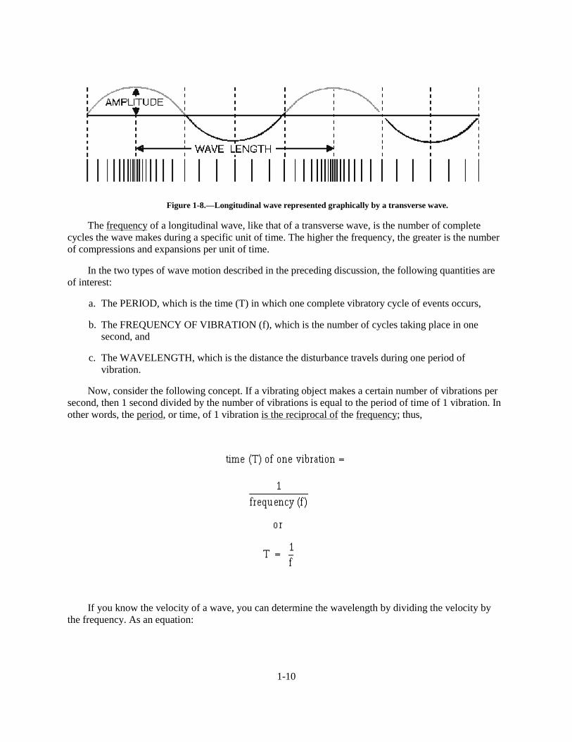
The two types of wave motion, transverse and longitudinal, have many of the same characteristics,such as frequency, amplitude, and wavelength. Another important characteristic that these two types ofwave motion share is VELOCITY. Velocity of propagation is the rate at which the disturbance travelsthrough the medium, or the velocity with which the crest of the wave moves along. The velocity of thewave depends both on the type of wave (light, sound, or radio) and type of medium (air, water, or metal).If longitudinal waves are plotted as a graph, they appear as transverse waves. This fact is illustrated infigure 1-8.
1-10
Figure 1-8.—Longitudinal wave represented graphically by a transverse wave.
The frequency of a longitudinal wave, like that of a transverse wave, is the number of completecycles the wave makes during a specific unit of time. The higher the frequency, the greater is the numberof compressions and expansions per unit of time.
In the two types of wave motion described in the preceding discussion, the following quantities areof interest:
a. The PERIOD, which is the time (T) in which one complete vibratory cycle of events occurs,
b. The FREQUENCY OF VIBRATION (f), which is the number of cycles taking place in onesecond, and
c. The WAVELENGTH, which is the distance the disturbance travels during one period ofvibration.
Now, consider the following concept. If a vibrating object makes a certain number of vibrations persecond, then 1 second divided by the number of vibrations is equal to the period of time of 1 vibration. Inother words, the period, or time, of 1 vibration is the reciprocal of the frequency; thus,
If you know the velocity of a wave, you can determine the wavelength by dividing the velocity bythe frequency. As an equation:
1-11
When you use the above equation, be careful to express velocity and wavelength in the proper unitsof length. For example, in the English system, if the velocity (expressed in feet per second) is divided bythe frequency (expressed in cycles per second, or Hz), the wavelength is given in feet per cycle. If themetric system is used and the velocity (expressed in meters per second) is divided by the frequency(expressed in cycles per second), the wavelength is given in meters per cycle. Be sure to express both thewavelength and the frequency in the same units. (Feet per cycle and meters per cycle are normallyabbreviated as feet or meters because one wavelength indicates one cycle.) Because this equation holdstrue for both transverse and longitudinal waves, it is used in the study of both electromagnetic waves andsound waves.
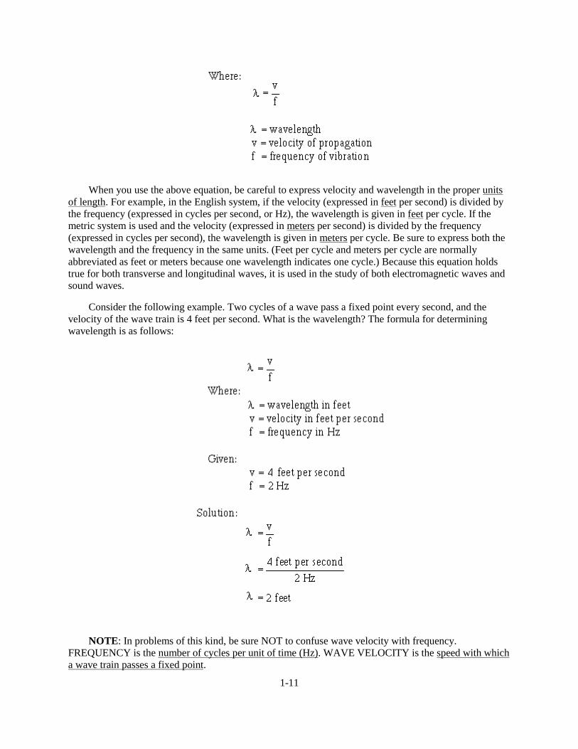
Consider the following example. Two cycles of a wave pass a fixed point every second, and thevelocity of the wave train is 4 feet per second. What is the wavelength? The formula for determiningwavelength is as follows:
NOTE: In problems of this kind, be sure NOT to confuse wave velocity with frequency.FREQUENCY is the number of cycles per unit of time (Hz). WAVE VELOCITY is the speed with whicha wave train passes a fixed point.
1-12
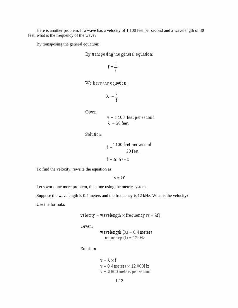
Here is another problem. If a wave has a velocity of 1,100 feet per second and a wavelength of 30feet, what is the frequency of the wave?
By transposing the general equation:
To find the velocity, rewrite the equation as:
v = I
Let’s work one more problem, this time using the metric system.
Suppose the wavelength is 0.4 meters and the frequency is 12 kHz. What is the velocity?
Use the formula:
1-13
Other important characteristics of wave motion are reflection, refraction, diffraction, and the Dopplereffect. Big words, but the concept of each is easy to see. For ease of understanding, we will explain thefirst two characteristics using light waves, and the last two characteristics using sound waves. You shouldkeep in mind that all waves react in a similar manner.
Within mediums, such as air, solids, or gases, a wave travels in a straight line. When the wave leavesthe boundary of one medium and enters the boundary of a different medium, the wave changes direction.For our purposes in this module, a boundary is an imaginary line that separates one medium from another.
When a wave passes through one medium and encounters a medium having different characteristics,three things can occur to the wave: (1) Some of the energy can be reflected back into the initial medium;(2) some of the energy can be transmitted into the second medium where it may continue at a differentvelocity; or (3) some of the energy can be absorbed by the medium. In some cases, all three processes(reflection, transmission, and absorption) may occur to some degree.
Reflection
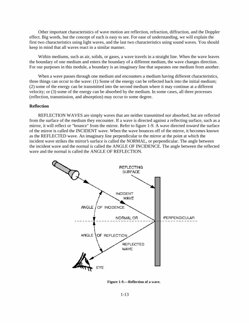
REFLECTION WAVES are simply waves that are neither transmitted nor absorbed, but are reflectedfrom the surface of the medium they encounter. If a wave is directed against a reflecting surface, such as amirror, it will reflect or "bounce" from the mirror. Refer to figure 1-9. A wave directed toward the surfaceof the mirror is called the INCIDENT wave. When the wave bounces off of the mirror, it becomes knownas the REFLECTED wave. An imaginary line perpendicular to the mirror at the point at which theincident wave strikes the mirror’s surface is called the NORMAL, or perpendicular. The angle betweenthe incident wave and the normal is called the ANGLE OF INCIDENCE. The angle between the reflectedwave and the normal is called the ANGLE OF REFLECTION.
Figure 1-9.—Reflection of a wave.
1-14
If the reflecting surface is smooth and polished, the angle between the incident ray and the normalwill be the same as the angle between the reflected ray and the normal. This conforms to the law ofreflection which states: The angle of incidence is equal to the angle of reflection.
The amount of incident wave energy reflected from a given surface depends on the nature of thesurface and the angle at which the wave strikes the surface. As the angle of incidence increases, theamount of wave energy reflected increases. The reflected energy is the greatest when the wave is nearlyparallel to the reflecting surface. When the incident wave is perpendicular to the surface, more of theenergy is transmitted into the substance and less is reflected. At any incident angle, a mirror reflectsalmost all of the wave energy, while a dull, black surface reflects very little.
Q11. What is the law of reflection?
Q12. When a wave is reflected from a surface, energy is transferred. When is the transfer of energygreatest?
Q13. When is the transfer of energy minimum?
Refraction
When a wave passes from one medium into another medium that has a different velocity ofpropagation, a change in the direction of the wave will occur. This changing of direction as the waveenters the second medium is called REFRACTION. As in the discussion of reflection, the wave strikingthe boundary (surface) is called the INCIDENT WAVE, and the imaginary line perpendicular to theboundary is called the NORMAL. The angle between the incident wave and the normal is called theANGLE OF INCIDENCE. As the wave passes through the boundary, it is bent either toward or awayfrom the normal. The angle between the normal and the path of the wave through the second medium isthe ANGLE OF REFRACTION.
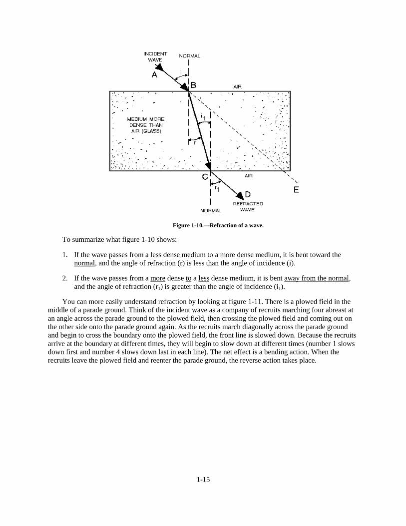
A light wave passing through a block of glass is shown in figure 1-10. The wave moves from point Ato B at a constant speed. This is the incident wave. As the wave penetrates the glass boundary at point B,the velocity of the wave is slowed down. This causes the wave to bend toward the normal. The wave thentakes the path from point B to C through the glass and becomes BOTH the refracted wave from the topsurface and the incident wave to the lower surface. As the wave passes from the glass to the air (thesecond boundary), it is again refracted, this time away from the normal and takes the path from point C toD. As the wave passes through the last boundary, its velocity increases to the original velocity. As figure1-10 shows, refracted waves can bend toward or away from the normal. This bending depends on thevelocity of the wave through each medium. The broken line between points B and E is the path that thewave would travel if the two mediums (air and glass) had the same density.
1-15
Figure 1-10.—Refraction of a wave.
To summarize what figure 1-10 shows:
1. If the wave passes from a less dense medium to a more dense medium, it is bent toward thenormal, and the angle of refraction (r) is less than the angle of incidence (i).
2. If the wave passes from a more dense to a less dense medium, it is bent away from the normal,and the angle of refraction (r1) is greater than the angle of incidence (i1).
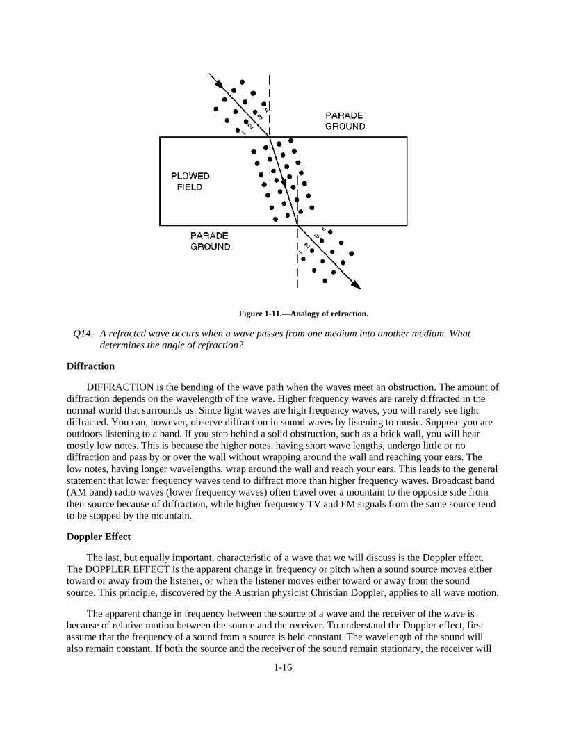
You can more easily understand refraction by looking at figure 1-11. There is a plowed field in themiddle of a parade ground. Think of the incident wave as a company of recruits marching four abreast atan angle across the parade ground to the plowed field, then crossing the plowed field and coming out onthe other side onto the parade ground again. As the recruits march diagonally across the parade groundand begin to cross the boundary onto the plowed field, the front line is slowed down. Because the recruitsarrive at the boundary at different times, they will begin to slow down at different times (number 1 slowsdown first and number 4 slows down last in each line). The net effect is a bending action. When therecruits leave the plowed field and reenter the parade ground, the reverse action takes place.
1-16
Figure 1-11.—Analogy of refraction.
Q14. A refracted wave occurs when a wave passes from one medium into another medium. Whatdetermines the angle of refraction?
Diffraction
DIFFRACTION is the bending of the wave path when the waves meet an obstruction. The amount ofdiffraction depends on the wavelength of the wave. Higher frequency waves are rarely diffracted in thenormal world that surrounds us. Since light waves are high frequency waves, you will rarely see lightdiffracted. You can, however, observe diffraction in sound waves by listening to music. Suppose you areoutdoors listening to a band. If you step behind a solid obstruction, such as a brick wall, you will hearmostly low notes. This is because the higher notes, having short wave lengths, undergo little or nodiffraction and pass by or over the wall without wrapping around the wall and reaching your ears. Thelow notes, having longer wavelengths, wrap around the wall and reach your ears. This leads to the generalstatement that lower frequency waves tend to diffract more than higher frequency waves. Broadcast band(AM band) radio waves (lower frequency waves) often travel over a mountain to the opposite side fromtheir source because of diffraction, while higher frequency TV and FM signals from the same source tendto be stopped by the mountain.
Doppler Effect
The last, but equally important, characteristic of a wave that we will discuss is the Doppler effect.The DOPPLER EFFECT is the apparent change in frequency or pitch when a sound source moves eithertoward or away from the listener, or when the listener moves either toward or away from the soundsource. This principle, discovered by the Austrian physicist Christian Doppler, applies to all wave motion.
The apparent change in frequency between the source of a wave and the receiver of the wave isbecause of relative motion between the source and the receiver. To understand the Doppler effect, firstassume that the frequency of a sound from a source is held constant. The wavelength of the sound willalso remain constant. If both the source and the receiver of the sound remain stationary, the receiver will
1-17
hear the same frequency sound produced by the source. This is because the receiver is receiving the samenumber of waves per second that the source is producing. Now, if either the source or the receiver or bothmove toward the other, the receiver will perceive a higher frequency sound. This is because the receiverwill receive a greater number of sound waves per second and interpret the greater number of waves as ahigher frequency sound. Conversely, if the source and the receiver are moving apart, the receiver willreceive a smaller number of sound waves per second and will perceive a lower frequency sound. In bothcases, the frequency of the sound produced by the source will have remained constant.
For example, the frequency of the whistle on a fast-moving train sounds increasingly higher in pitchas the train is approaching than when the train is departing. Although the whistle is generating soundwaves of a constant frequency, and though they travel through the air at the same velocity in alldirections, the distance between the approaching train and the listener is decreasing. As a result, eachwave has less distance to travel to reach the observer than the wave preceding it. Thus, the waves arrivewith decreasing intervals of time between them.
These apparent changes in frequency, called the Doppler effect, affect the operation of equipmentused to detect and measure wave energy. In dealing with electromagnetic wave propagation, the Dopplerprinciple is used in equipment such as radar, target detection, weapons control, navigation, and sonar.
Q15. The apparent change in frequency or pitch because of motion is explained by what effect?
SOUND WAVES
The study of sound is important because of the role sound plays in the depth finding equipment(fathometer) and underwater detection equipment (sonar) used by the Navy.
As you know, sound travels through a medium by wave motion. Although sound waves and theelectromagnetic waves used in the propagation of radio and radar differ, both types of waves have manyof the same characteristics. Studying the principles of sound-wave motion will help you understand theactions of both sound waves and the more complex radio and radar electromagnetic waves. The majordifferences among sound waves, heat waves, and light waves are (1) their frequencies; (2) their types; themediums through which they travel; and the velocities at which they travel.
SOUND—WHAT IS IT?
The word SOUND is used in everyday speech to signify a variety of things. One definition of soundis the sensation of hearing. Another definition refers to a stimulus that is capable of producing thesensation of hearing. A third definition limits sound to what is actually heard by the human ear.
In the study of physics, sound is defined as a range of compression-wave frequencies to which thehuman ear is sensitive. For the purpose of this chapter, however, we need to broaden the definition ofsound to include compression waves that are not always audible to the human ear. To distinguishfrequencies in the audible range from those outside that range, the words SONIC, ULTRASONIC, andINFRASONIC are used. Sounds capable of being heard by the human ear are called SONICS. The normalhearing range extends from about 20 to 20,000 hertz. However, to establish a standard sonic range, theNavy has set an arbitrary upper limit for sonics at 10,000 hertz and a lower limit at 15 hertz. Even thoughthe average person can hear sounds above 10,000 hertz, it is standard practice to refer to sounds abovethat frequency as ultrasonic. Sounds between 15 hertz and 10,000 hertz are called sonic, while soundsbelow 15 hertz are known as infrasonic (formerly referred to as subsonic) sounds.
1-18
Q16. What term describes sounds capable of being heard by the human ear?
Q17. Are all sounds audible to the human ear? Why?
REQUIREMENTS FOR SOUND
Recall that sound waves are compression waves. The existence of compression waves depends onthe transfer of energy. To produce vibrations that become sounds, a mechanical device (the source) mustfirst receive an input of energy. Next, the device must be in contact with a medium that will receive thesound energy and carry it to a receiver. If the device is not in contact with a medium, the energy will notbe transferred to a receiver, and there will be no sound.
Thus, three basic elements for transmission and reception of sound must be present before a soundcan be produced. They are (1) the source (or transmitter), (2) a medium for carrying the sound (air, water,metal, etc.), and (3) the detector (or receiver).
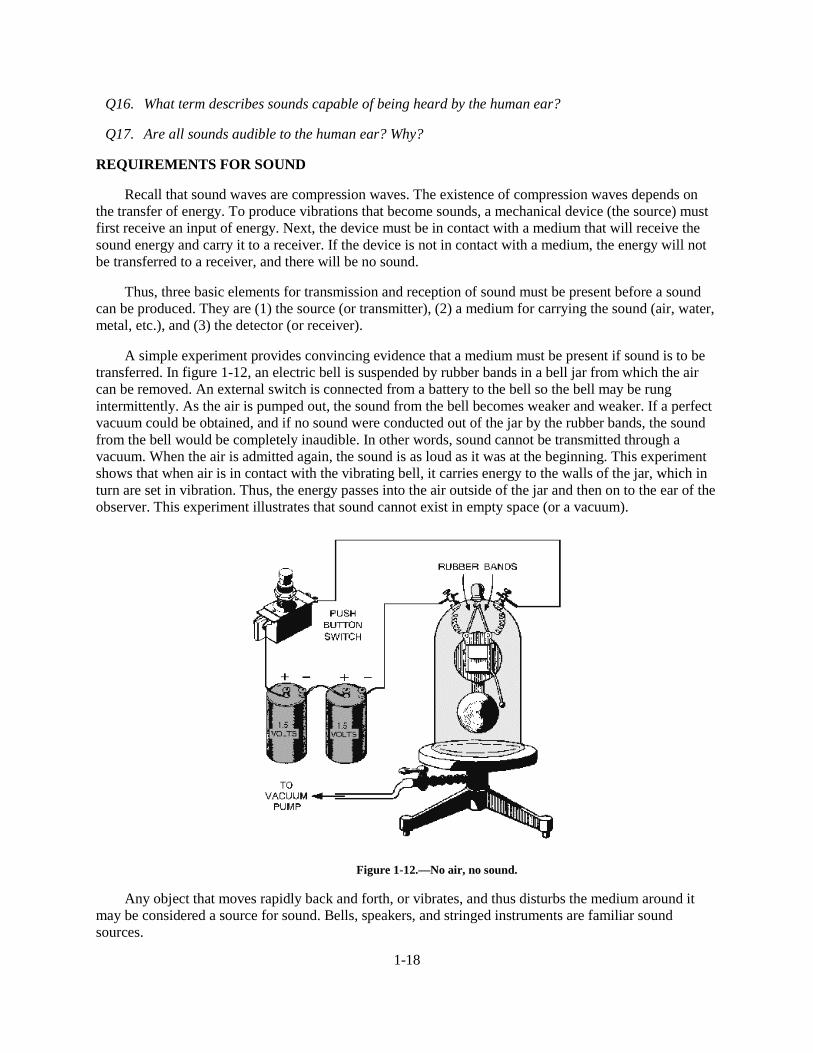
A simple experiment provides convincing evidence that a medium must be present if sound is to betransferred. In figure 1-12, an electric bell is suspended by rubber bands in a bell jar from which the aircan be removed. An external switch is connected from a battery to the bell so the bell may be rungintermittently. As the air is pumped out, the sound from the bell becomes weaker and weaker. If a perfectvacuum could be obtained, and if no sound were conducted out of the jar by the rubber bands, the soundfrom the bell would be completely inaudible. In other words, sound cannot be transmitted through avacuum. When the air is admitted again, the sound is as loud as it was at the beginning. This experimentshows that when air is in contact with the vibrating bell, it carries energy to the walls of the jar, which inturn are set in vibration. Thus, the energy passes into the air outside of the jar and then on to the ear of theobserver. This experiment illustrates that sound cannot exist in empty space (or a vacuum).
Figure 1-12.—No air, no sound.
Any object that moves rapidly back and forth, or vibrates, and thus disturbs the medium around itmay be considered a source for sound. Bells, speakers, and stringed instruments are familiar soundsources.
1-19
The material through which sound waves travel is called the medium. The density of the mediumdetermines the ease, distance, and speed of sound transmission. The higher the density of the medium, theslower sound travels through it.
The detector acts as the receiver of the sound wave. Because it does not surround the source of thesound wave, the detector absorbs only part of the energy from the wave and sometimes requires anamplifier to boost the weak signal.
As an illustration of what happens if one of these three elements is not present, let’s refer to ourexperiment in which a bell was placed in a jar containing a vacuum. You could see the bell being struck,but you could hear no sound because there was no medium to transmit sound from the bell to you. Nowlet’s look at another example in which the third element, the detector, is missing. You see a source (suchas an explosion) apparently producing a sound, and you know the medium (air) is present, but you are toofar away to hear the noise. Thus, as far as you are concerned, there is no detector and, therefore, no sound.We must assume, then, that sound can exist only when a source transmits sound through a medium, whichpasses it to a detector. Therefore, in the absence of any one of the basic elements (source, medium,detector) there can be NO sound.
Q18. Sound waves transmitted from a source are sometimes weak when they reach the detector. Whatinstrument is needed to boost the weak signal?
TERMS USED IN SOUND WAVES
Sound waves vary in length according to their frequency. A sound having a long wavelength is heardat a low pitch (low frequency); one with a short wavelength is heard at a high pitch (high frequency). Acomplete wavelength is called a cycle. The distance from one point on a wave to the corresponding pointon the next wave is a wavelength. The number of cycles per second (hertz) is the frequency of the sound.The frequency of a sound wave is also the number of vibrations per second produced by the sound source.
Q19. What are the three basic requirements for sound?
CHARACTERISTICS OF SOUND
Sound waves travel at great distances in a very short time, but as the distance increases the wavestend to spread out. As the sound waves spread out, their energy simultaneously spreads through anincreasingly larger area. Thus, the wave energy becomes weaker as the distance from the source isincreased.
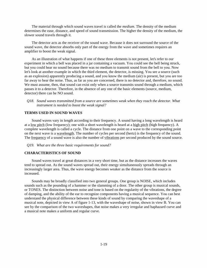
Sounds may be broadly classified into two general groups. One group is NOISE, which includessounds such as the pounding of a hammer or the slamming of a door. The other group is musical sounds,or TONES. The distinction between noise and tone is based on the regularity of the vibrations, the degreeof damping, and the ability of the ear to recognize components having a musical sequence. You can bestunderstand the physical difference between these kinds of sound by comparing the waveshape of amusical note, depicted in view A of figure 1-13, with the waveshape of noise, shown in view B. You cansee by the comparison of the two waveshapes, that noise makes a very irregular and haphazard curve anda musical note makes a uniform and regular curve.
1-20
Figure 1-13.—Musical sound versus noise.
Sound has three basic characteristics: pitch, intensity, and quality. Each of these three characteristicsis associated with one of the properties of the source or the type of waves which it produces. The pitchdepends upon the frequency of the waves; the intensity depends upon the amplitude of the waves; and thequality depends upon the form of the waves. With the proper combination of these characteristics, thetone is pleasant to the ear. With the wrong combination, the sound quality turns into noise.
The Pitch of Sound
The term PITCH is used to describe the frequency of a sound. An object that vibrates many times persecond produces a sound with a high pitch, as with a police whistle. The slow vibrations of the heavierstrings of a violin cause a low-pitched sound. Thus, the frequency of the wave determines pitch. When thefrequency is low, sound waves are long; when it is high, the waves are short. A sound can be so high infrequency that the waves reaching the ear cannot be heard. Likewise, some frequencies are so low that theeardrums do not convert them into sound. The range of sound that the human ear can detect varies witheach individual.
The Intensity of Sound
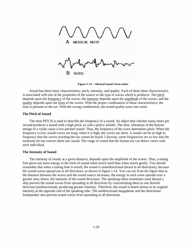
The intensity of sound, at a given distance, depends upon the amplitude of the waves. Thus, a tuningfork gives out more energy in the form of sound when struck hard than when struck gently. You shouldremember that when a tuning fork is struck, the sound is omnidirectional (heard in all directions), becausethe sound waves spread out in all directions, as shown in figure 1-14. You can see from the figure that asthe distance between the waves and the sound source increases, the energy in each wave spreads over agreater area; hence, the intensity of the sound decreases. The speaking tubes sometimes used aboard aship prevent the sound waves from spreading in all directions by concentrating them in one desireddirection (unidirectional), producing greater intensity. Therefore, the sound is heard almost at its originalintensity at the opposite end of the speaking tube. The unidirectional megaphone and the directionalloudspeaker also prevent sound waves from spreading in all directions.
1-21
Figure 1-14.—Sound waves spread in all directions.
Sound intensity and loudness are often mistakenly interpreted as having the same meaning. Althoughthey are related, they are not the same. Sound INTENSITY is a measure of the sound energy of a wave.LOUDNESS, on the other hand, is the sensation the intensity (and sometimes frequency) the sound waveproduces on the ear. Increasing the intensity causes an increase in loudness but not in a direct proportion.For instance, doubling the loudness of a sound requires about a tenfold increase in the intensity of thesound.
Sound Quality
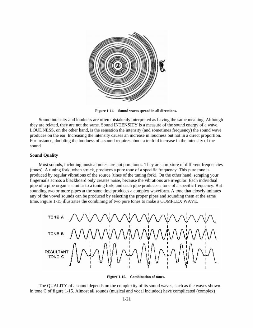
Most sounds, including musical notes, are not pure tones. They are a mixture of different frequencies(tones). A tuning fork, when struck, produces a pure tone of a specific frequency. This pure tone isproduced by regular vibrations of the source (tines of the tuning fork). On the other hand, scraping yourfingernails across a blackboard only creates noise, because the vibrations are irregular. Each individualpipe of a pipe organ is similar to a tuning fork, and each pipe produces a tone of a specific frequency. Butsounding two or more pipes at the same time produces a complex waveform. A tone that closely imitatesany of the vowel sounds can be produced by selecting the proper pipes and sounding them at the sametime. Figure 1-15 illustrates the combining of two pure tones to make a COMPLEX WAVE.
Figure 1-15.—Combination of tones.
The QUALITY of a sound depends on the complexity of its sound waves, such as the waves shownin tone C of figure 1-15. Almost all sounds (musical and vocal included) have complicated (complex)
1-22
waveforms. Tone A is a simple wave of a specific frequency that can be produced by a tuning fork, piano,organ, or other musical instrument. Tone B is also a simple wave but at a different frequency. When thetwo tones are sounded together, the complex waveform in tone C is produced. Note that tone C has thesame frequency as tone A with an increase in amplitude. The human ear could easily distinguish betweentone A and tone C because of the quality. Therefore, we can say that quality distinguishes tones of likepitch and loudness when sounded on different types of musical instruments. It also distinguishes thevoices of different persons.
Q20. What are the two general groups of sound?
Q21. What are the three basic characteristics of sound?
Q22. What is the normal audible range of the human ear?
Q23. What is intensity as it pertains to sound?
Q24. What characteristic of sound enables a person to distinguish one musical instrument fromanother, if they are all playing the same note?
ELASTICITY AND DENSITY AND VELOCITY OF TRANSMISSION
Sound waves travel through any medium to a velocity that is controlled by the medium. Varying thefrequency and intensity of the sound waves will not affect the speed of propagation. The ELASTICITYand DENSITY of a medium are the two basic physical properties that govern the velocity of soundthrough the medium.
Elasticity is the ability of a strained body to recover its shape after deformation, as from a vibrationor compression. The measure of elasticity of a body is the force it exerts to return to its original shape.
The density of a medium or substance is the mass per unit volume of the medium or substance.Raising the temperature of the medium (which decreases its density) has the effect of increasing thevelocity of sound through the medium.
The velocity of sound in an elastic medium is expressed by the formula:
Even though solids such as steel and glass are far more dense than air, their elasticity’s are so muchgreater that the velocities of sound in them are 15 times greater than the velocity of sound in air. Usingelasticity as a rough indication of the speed of sound in a given medium, we can state as a general rulethat sound travels faster in harder materials (such as steel), slower in liquids, and slowest in gases.Density has the opposite effect on the velocity of sound, that is, with other factors constant, a densermaterial (such as lead) passes sound slower.
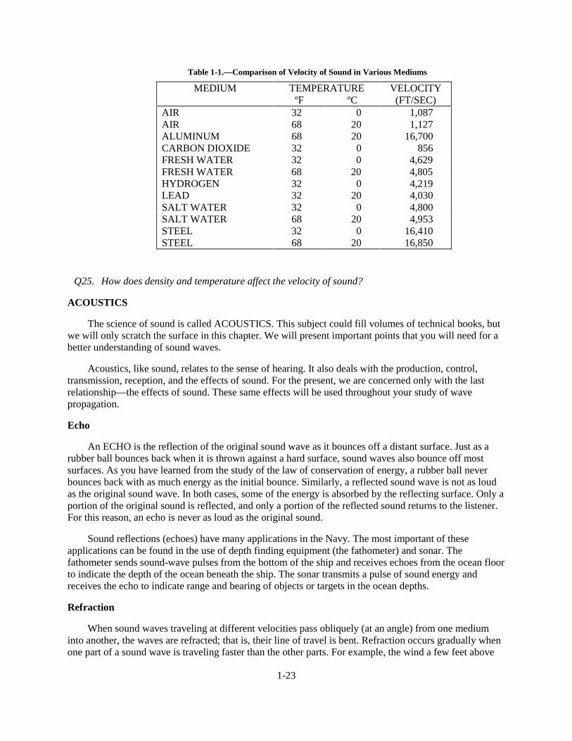
At a given temperature and atmospheric pressure, all sound waves travel in air at the same speed.Thus the velocity that sound will travel through air at 32º F (0º C) is 1,087 feet per second. But forpractical purposes, the speed of sound in air may be considered as 1,100 feet per second. Table 1-1 givesa comparison of the velocity of sound in various mediums.
1-23
Table 1-1.—Comparison of Velocity of Sound in Various Mediums
MEDIUM TEMPERATURE VELOCITYºF ºC (FT/SEC)
AIR 32 0 1,087AIR 68 20 1,127ALUMINUM 68 20 16,700CARBON DIOXIDE 32 0 856FRESH WATER 32 0 4,629FRESH WATER 68 20 4,805HYDROGEN 32 0 4,219LEAD 32 20 4,030SALT WATER 32 0 4,800SALT WATER 68 20 4,953STEEL 32 0 16,410STEEL 68 20 16,850
Q25. How does density and temperature affect the velocity of sound?
ACOUSTICS
The science of sound is called ACOUSTICS. This subject could fill volumes of technical books, butwe will only scratch the surface in this chapter. We will present important points that you will need for abetter understanding of sound waves.
Acoustics, like sound, relates to the sense of hearing. It also deals with the production, control,transmission, reception, and the effects of sound. For the present, we are concerned only with the lastrelationship—the effects of sound. These same effects will be used throughout your study of wavepropagation.
Echo
An ECHO is the reflection of the original sound wave as it bounces off a distant surface. Just as arubber ball bounces back when it is thrown against a hard surface, sound waves also bounce off mostsurfaces. As you have learned from the study of the law of conservation of energy, a rubber ball neverbounces back with as much energy as the initial bounce. Similarly, a reflected sound wave is not as loudas the original sound wave. In both cases, some of the energy is absorbed by the reflecting surface. Only aportion of the original sound is reflected, and only a portion of the reflected sound returns to the listener.For this reason, an echo is never as loud as the original sound.
Sound reflections (echoes) have many applications in the Navy. The most important of theseapplications can be found in the use of depth finding equipment (the fathometer) and sonar. Thefathometer sends sound-wave pulses from the bottom of the ship and receives echoes from the ocean floorto indicate the depth of the ocean beneath the ship. The sonar transmits a pulse of sound energy andreceives the echo to indicate range and bearing of objects or targets in the ocean depths.
Refraction
When sound waves traveling at different velocities pass obliquely (at an angle) from one mediuminto another, the waves are refracted; that is, their line of travel is bent. Refraction occurs gradually whenone part of a sound wave is traveling faster than the other parts. For example, the wind a few feet above
1-24
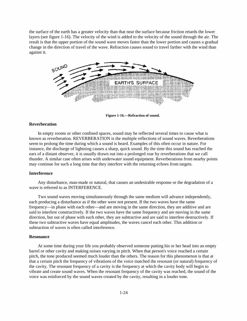
the surface of the earth has a greater velocity than that near the surface because friction retards the lowerlayers (see figure 1-16). The velocity of the wind is added to the velocity of the sound through the air. Theresult is that the upper portion of the sound wave moves faster than the lower portion and causes a gradualchange in the direction of travel of the wave. Refraction causes sound to travel farther with the wind thanagainst it.
Figure 1-16.—Refraction of sound.
Reverberation
In empty rooms or other confined spaces, sound may be reflected several times to cause what isknown as reverberation. REVERBERATION is the multiple reflections of sound waves. Reverberationsseem to prolong the time during which a sound is heard. Examples of this often occur in nature. Forinstance, the discharge of lightning causes a sharp, quick sound. By the time this sound has reached theears of a distant observer, it is usually drawn out into a prolonged roar by reverberations that we callthunder. A similar case often arises with underwater sound equipment. Reverberations from nearby pointsmay continue for such a long time that they interfere with the returning echoes from targets.
Interference
Any disturbance, man-made or natural, that causes an undesirable response or the degradation of awave is referred to as INTERFERENCE.
Two sound waves moving simultaneously through the same medium will advance independently,each producing a disturbance as if the other were not present. If the two waves have the samefrequency—in phase with each other—and are moving in the same direction, they are additive and aresaid to interfere constructively. If the two waves have the same frequency and are moving in the samedirection, but out of phase with each other, they are subtractive and are said to interfere destructively. Ifthese two subtractive waves have equal amplitudes, the waves cancel each other. This addition orsubtraction of waves is often called interference.
Resonance
At some time during your life you probably observed someone putting his or her head into an emptybarrel or other cavity and making noises varying in pitch. When that person's voice reached a certainpitch, the tone produced seemed much louder than the others. The reason for this phenomenon is that atthat a certain pitch the frequency of vibrations of the voice matched the resonant (or natural) frequency ofthe cavity. The resonant frequency of a cavity is the frequency at which the cavity body will begin tovibrate and create sound waves. When the resonant frequency of the cavity was reached, the sound of thevoice was reinforced by the sound waves created by the cavity, resulting in a louder tone.
1-25
This phenomenon occurs whenever the frequency of vibrations is the same as the natural frequencyof a cavity, and is called RESONANCE.
Noise
The most complex sound wave that can be produced is noise. Noise has no tonal quality. It distractsand distorts the sound quality that was intended to be heard. NOISE is generally an unwanted disturbancecaused by spurious waves originating from man-made or natural sources, such as a jet breaking the soundbarrier, or thunder.
Q26. What term is used in describing the science of sound?
Q27. A sound wave that is reflected back toward the source is known as what type of sound?
Q28. What is the term for multiple reflections of sound waves?
Q29. A cavity that vibrates at its natural frequency produces a louder sound than at other frequencies.What term is used to describe this phenomenon?
Q30. What do we call a disturbance that distracts or distorts the quality of sound?
LIGHT WAVES
Technicians maintain equipment that use frequencies from one end of the electromagnetic spectrumto the other—from low-frequency radio waves to high-frequency X-rays and cosmic rays. Visible light isa small but very important part of this electromagnetic spectrum.
Most of the important terms that pertain to the behavior of waves, such as reflection, refraction,diffraction, etc., were discussed earlier in this chapter. We will now discuss how these terms are used inunderstanding light and light waves. The relationship between light and light waves (rays) is the same assound and sound waves.
Light is a form of energy. It can be produced by various means (mechanical, electrical, chemical,etc.). We can see objects because the light rays they give off or reflect reach our eyes. If the object is thesource of light energy, it is called luminous. If the object is not the source of light but reflects light, it iscalled an illuminated body.
PROPAGATION OF LIGHT
The exact nature of light is not fully understood, although scientists have been studying the subjectfor many centuries. Some experiments seem to show that light is composed of tiny particles, and somesuggest that it is made up of waves.
One theory after another attracted the approval and acceptance of physicists. Today, some scientificphenomena can be explained only by the wave theory and others only by the particle theory. Physicists,constantly searching for some new discovery that would bring these two theories into agreement,gradually have come to accept a theory that combines the principles of the two theories.
According to the view now generally accepted, light is a form of electromagnetic radiation; that is,light and similar forms of radiation are made up of moving electric and magnetic fields. These two fieldswill be explained thoroughly later in this chapter.
1-26
ELECTROMAGNETIC THEORY OF LIGHT
James Clark Maxwell, a brilliant Scottish scientist Of the middle l9th century, showed, byconstructing an oscillating electrical circuit, that electromagnetic waves could move through empty space.Light eventually was proved to be electromagnetic.
Current light theory says that light is made up of very small packets of electromagnetic energy calledPHOTONS (the smallest unit of radiant energy). These photons move at a constant speed in the mediumthrough which they travel. Photons move at a faster speed through a vacuum than they do in theatmosphere, and at a slower speed through water than air.
The electromagnetic energy of light is a form of electromagnetic radiation. Light and similar formsof radiation are made up of moving electric and magnetic forces and move as waves. Electromagneticwaves move in a manner similar to the waves produced by the pebble dropped in the pool of waterdiscussed earlier in this chapter. The transverse waves of light from a light source spread out in expandingcircles much like the waves in the pool. However, the waves in the pool are very slow and clumsy incomparison with light, which travels approximately 186,000 miles per second.
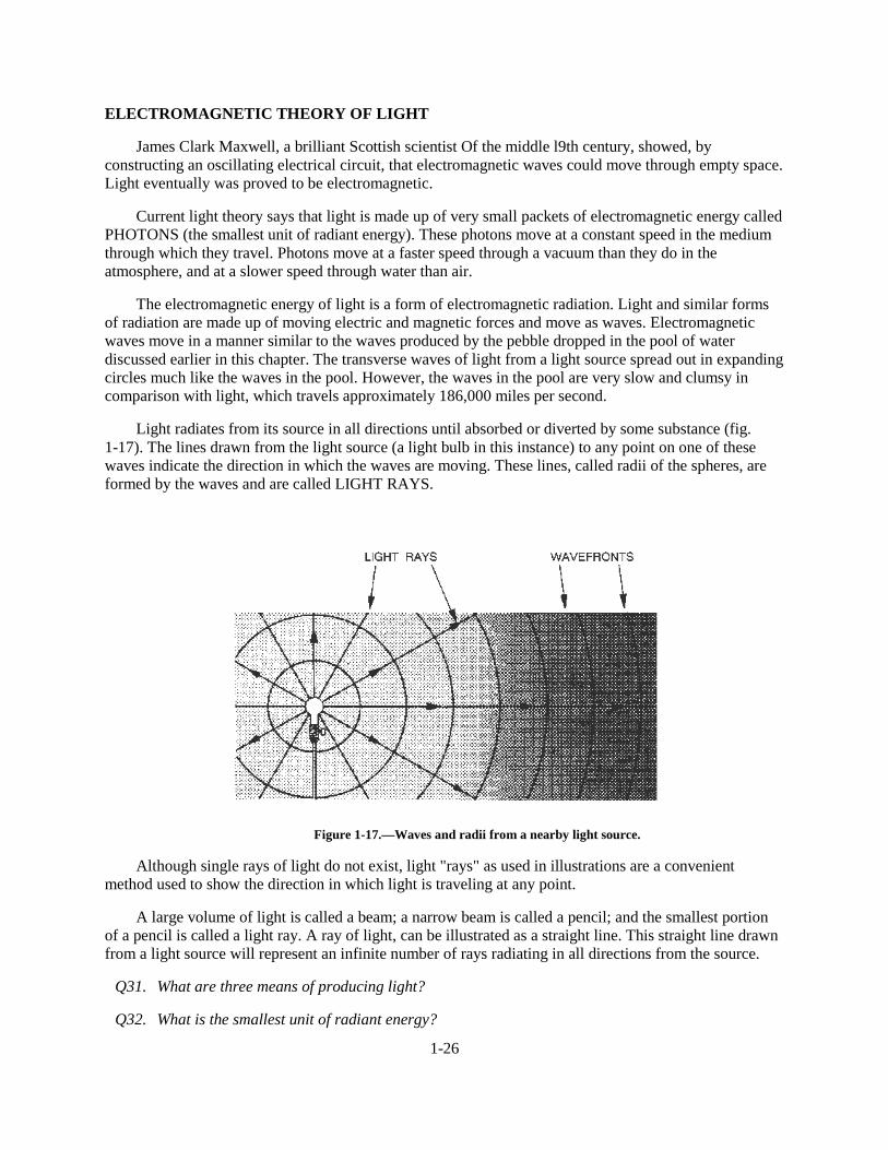
Light radiates from its source in all directions until absorbed or diverted by some substance (fig.1-17). The lines drawn from the light source (a light bulb in this instance) to any point on one of thesewaves indicate the direction in which the waves are moving. These lines, called radii of the spheres, areformed by the waves and are called LIGHT RAYS.
Figure 1-17.—Waves and radii from a nearby light source.
Although single rays of light do not exist, light "rays" as used in illustrations are a convenientmethod used to show the direction in which light is traveling at any point.
A large volume of light is called a beam; a narrow beam is called a pencil; and the smallest portionof a pencil is called a light ray. A ray of light, can be illustrated as a straight line. This straight line drawnfrom a light source will represent an infinite number of rays radiating in all directions from the source.
Q31. What are three means of producing light?
Q32. What is the smallest unit of radiant energy?
1-27
FREQUENCIES AND WAVELENGTHS
Compared to sound waves, the frequency of light waves is very high and the wavelength is veryshort. To measure these wavelengths more conveniently, a special unit of measure called anANGSTROM UNIT, or more usually, an ANGSTROM ( ��ZDV�GHYLVHG��$QRWKHU�FRPPRQ�XQLW�XVHG�WRmeasure these waves is the millimicron (P ���ZKLFK�LV�RQH�PLOOLRQWK�RI�D�PLOOLPHWHU��2QH�P)�HTXDOV�WHQangstroms. One angstrom equals 1055-10m.
Q33. What unit is used to measure the different wavelengths of light?
FREQUENCIES AND COLOR
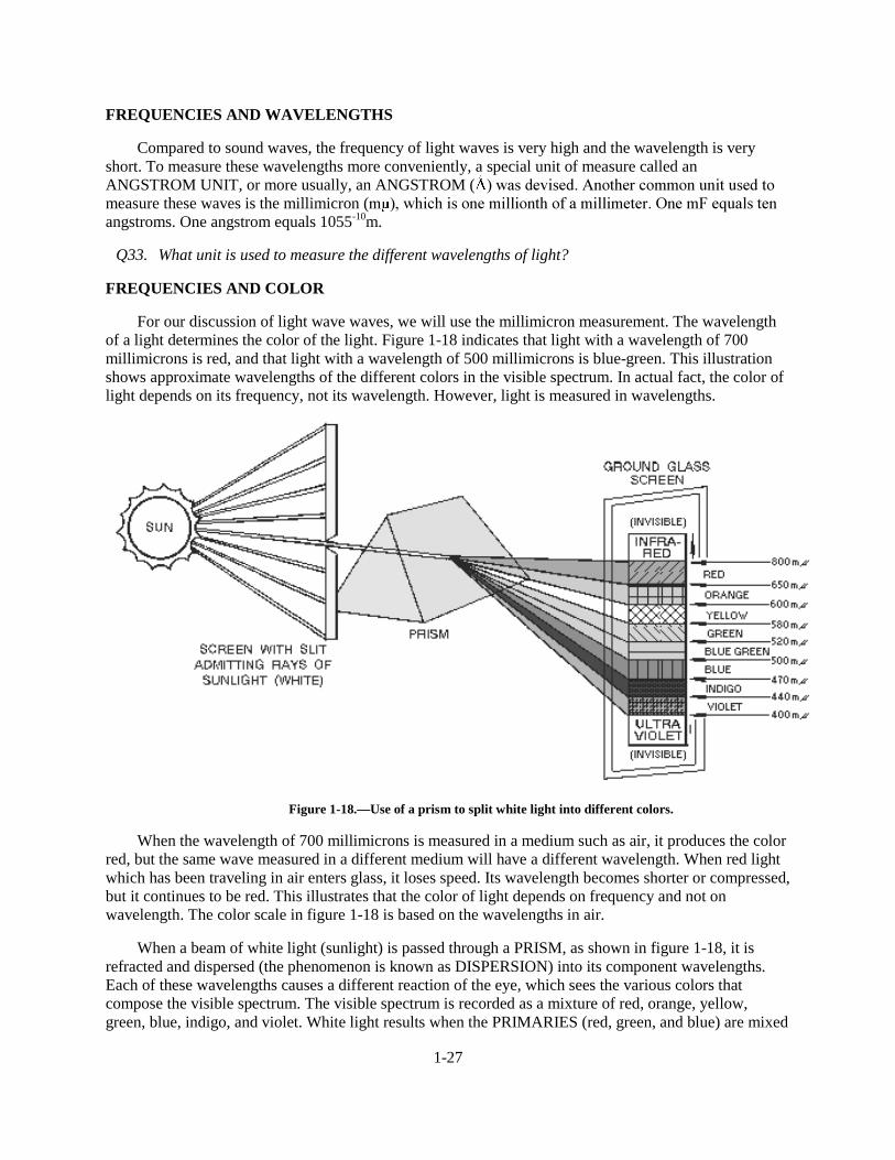
For our discussion of light wave waves, we will use the millimicron measurement. The wavelengthof a light determines the color of the light. Figure 1-18 indicates that light with a wavelength of 700millimicrons is red, and that light with a wavelength of 500 millimicrons is blue-green. This illustrationshows approximate wavelengths of the different colors in the visible spectrum. In actual fact, the color oflight depends on its frequency, not its wavelength. However, light is measured in wavelengths.
Figure 1-18.—Use of a prism to split white light into different colors.
When the wavelength of 700 millimicrons is measured in a medium such as air, it produces the colorred, but the same wave measured in a different medium will have a different wavelength. When red lightwhich has been traveling in air enters glass, it loses speed. Its wavelength becomes shorter or compressed,but it continues to be red. This illustrates that the color of light depends on frequency and not onwavelength. The color scale in figure 1-18 is based on the wavelengths in air.
When a beam of white light (sunlight) is passed through a PRISM, as shown in figure 1-18, it isrefracted and dispersed (the phenomenon is known as DISPERSION) into its component wavelengths.Each of these wavelengths causes a different reaction of the eye, which sees the various colors thatcompose the visible spectrum. The visible spectrum is recorded as a mixture of red, orange, yellow,green, blue, indigo, and violet. White light results when the PRIMARIES (red, green, and blue) are mixed
1-28
together in overlapping beams of light. (NOTE: These are not the primaries used in mixing pigments,such as in paint.) Furthermore, the COMPLEMENTARY or SECONDARY colors (magenta, yellow, andcyan) may be shown with equal ease by mixing any two of the primary colors in overlapping beams oflight. Thus, red and green light mixed in equal intensities will make yellow light; green and blue willproduce cyan (blue-green light); and blue and red correctly mixed will produce magenta (a purplish redlight).
LIGHT AND COLOR
All objects absorb some of the light that falls on them. An object appears to be a certain colorbecause it absorbs all of the light waves except those whose frequency corresponds to that particularcolor. Those waves are reflected from the surface, strike your eye, and cause you to see the particularcolor. The color of an object therefore depends on the frequency of the electromagnetic wave reflected.
LUMINOUS BODIES
Certain bodies, such as the sun, a gas flame, and an electric light filament, are visible because theyare light sources. They are called SELF-LUMINOUS bodies. Objects other than self-luminous bodiesbecome visible only when they are in the presence of light from luminous bodies.
Most NONLUMINOUS bodies are visible because they diffuse or reflect the light that falls on them.A good example of a nonluminous diffusing body is the moon, which shines only because the sunlightfalling onto its surface is diffused.
Black objects do not diffuse or reflect light. They are visible only when outlined against abackground of light from a luminous or diffusing body.
PROPERTIES OF LIGHT
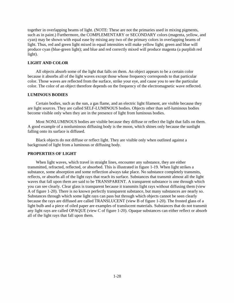
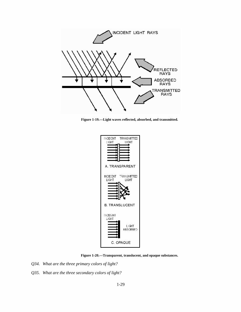
When light waves, which travel in straight lines, encounter any substance, they are eithertransmitted, refracted, reflected, or absorbed. This is illustrated in figure 1-19. When light strikes asubstance, some absorption and some reflection always take place. No substance completely transmits,reflects, or absorbs all of the light rays that reach its surface. Substances that transmit almost all the lightwaves that fall upon them are said to be TRANSPARENT. A transparent substance is one through whichyou can see clearly. Clear glass is transparent because it transmits light rays without diffusing them (viewA of figure 1-20). There is no known perfectly transparent substance, but many substances are nearly so.Substances through which some light rays can pass but through which objects cannot be seen clearlybecause the rays are diffused are called TRANSLUCENT (view B of figure 1-20). The frosted glass of alight bulb and a piece of oiled paper are examples of translucent materials. Substances that do not transmitany light rays are called OPAQUE (view C of figure 1-20). Opaque substances can either reflect or absorball of the light rays that fall upon them.
1-29
Figure 1-19.—Light waves reflected, absorbed, and transmitted.
Figure 1-20.—Transparent, translucent, and opaque substances.
Q34. What are the three primary colors of light?
Q35. What are the three secondary colors of light?
1-30
Q36. White light falls upon a dull, rough, dark-brown object. Will the light primarily be reflected,diffused, or absorbed by the object?
Q37. What color will be emitted by a dull, rough, black object when white light falls upon it?
Q38. A substance that transmits light but through which an object cannot be seen clearly is known aswhat kind of substance?
Speed of Light
You probably have heard people say, "quick as lightning" or "fast as light" to describe rapid motion;nevertheless, it is difficult to realize how fast light actually travels. Not until recent years have scientistsbeen able to measure accurately the speed of light.
Prior to the middle 17th century, scientists thought that light required no time at all to pass from thesource to the observer. Then in 1675, Ole Roemer, a Danish astronomer, discovered that light travelsapproximately 186,000 miles per second in space. At this velocity, a light beam can circle the earth 7 1/2times in one second.
The speed of light depends on the medium through which the light travels. In empty space, the speedis 186,000 (1.86 × 10⁵) miles per second. It is almost the same in air. In water, it slows down toapproximately 140,000 (1.4 × 10⁵) miles per second. In glass, the speed of light is 124,000 (1.24 × 10 5)miles per second. In other words, the speed of light decreases as the density of the substance throughwhich the light passes increases.
The velocity of light, which is the same as the velocity of other electromagnetic waves, is consideredto be constant, at 186,000 miles per second. If expressed in meters, it is 300,000,000 meters per second.
Reflection of Light
Light waves obey the law of reflection in the same manner as other types of waves. Consider thestraight path of a light ray admitted through a narrow slit into a darkened room. The straight path of thebeam is made visible by illuminated dust particles suspended in the air. If the light beam is made to fallonto the surface of a mirror or other reflecting surface, however, the direction of the beam changessharply. The light can be reflected in almost any direction depending on the angle at which the mirror isheld.
As shown earlier in figure 1-9, if a light beam strikes a mirror, the angle at which the beam isreflected depends on the angle at which it strikes the mirror. The beam approaching the mirror is theINCIDENT or striking beam, and the beam leaving the mirror is the REFLECTED beam.
The term "reflected light" simply refers to light waves that are neither transmitted nor absorbed, butare thrown back from the surface of the medium they encounter.
You will see this application used in our discussion of radio waves (chapter 2) and antennas (chapter4).
Q39. At what speed does light travel?
Refraction of Light
The change of direction that occurs when a ray of light passes from one transparent substance intoanother of different density is called refraction. Refraction is due to the fact that light travels at various
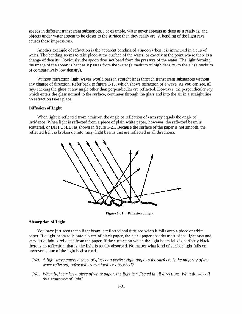
1-31
speeds in different transparent substances. For example, water never appears as deep as it really is, andobjects under water appear to be closer to the surface than they really are. A bending of the light rayscauses these impressions.
Another example of refraction is the apparent bending of a spoon when it is immersed in a cup ofwater. The bending seems to take place at the surface of the water, or exactly at the point where there is achange of density. Obviously, the spoon does not bend from the pressure of the water. The light formingthe image of the spoon is bent as it passes from the water (a medium of high density) to the air (a mediumof comparatively low density).
Without refraction, light waves would pass in straight lines through transparent substances withoutany change of direction. Refer back to figure 1-10, which shows refraction of a wave. As you can see, allrays striking the glass at any angle other than perpendicular are refracted. However, the perpendicular ray,which enters the glass normal to the surface, continues through the glass and into the air in a straight lineno refraction takes place.
Diffusion of Light
When light is reflected from a mirror, the angle of reflection of each ray equals the angle ofincidence. When light is reflected from a piece of plain white paper, however, the reflected beam isscattered, or DIFFUSED, as shown in figure 1-21. Because the surface of the paper is not smooth, thereflected light is broken up into many light beams that are reflected in all directions.
Figure 1-21.—Diffusion of light.
Absorption of Light
You have just seen that a light beam is reflected and diffused when it falls onto a piece of whitepaper. If a light beam falls onto a piece of black paper, the black paper absorbs most of the light rays andvery little light is reflected from the paper. If the surface on which the light beam falls is perfectly black,there is no reflection; that is, the light is totally absorbed. No matter what kind of surface light falls on,however, some of the light is absorbed.
Q40. A light wave enters a sheet of glass at a perfect right angle to the surface. Is the majority of thewave reflected, refracted, transmitted, or absorbed?
Q41. When light strikes a piece of white paper, the light is reflected in all directions. What do we callthis scattering of light?
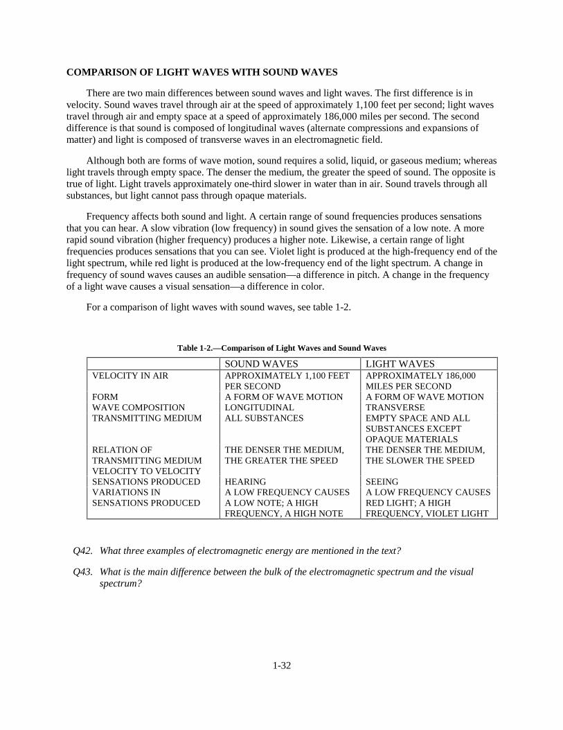
1-32
COMPARISON OF LIGHT WAVES WITH SOUND WAVES
There are two main differences between sound waves and light waves. The first difference is invelocity. Sound waves travel through air at the speed of approximately 1,100 feet per second; light wavestravel through air and empty space at a speed of approximately 186,000 miles per second. The seconddifference is that sound is composed of longitudinal waves (alternate compressions and expansions ofmatter) and light is composed of transverse waves in an electromagnetic field.
Although both are forms of wave motion, sound requires a solid, liquid, or gaseous medium; whereaslight travels through empty space. The denser the medium, the greater the speed of sound. The opposite istrue of light. Light travels approximately one-third slower in water than in air. Sound travels through allsubstances, but light cannot pass through opaque materials.
Frequency affects both sound and light. A certain range of sound frequencies produces sensationsthat you can hear. A slow vibration (low frequency) in sound gives the sensation of a low note. A morerapid sound vibration (higher frequency) produces a higher note. Likewise, a certain range of lightfrequencies produces sensations that you can see. Violet light is produced at the high-frequency end of thelight spectrum, while red light is produced at the low-frequency end of the light spectrum. A change infrequency of sound waves causes an audible sensation—a difference in pitch. A change in the frequencyof a light wave causes a visual sensation—a difference in color.
For a comparison of light waves with sound waves, see table 1-2.
Table 1-2.—Comparison of Light Waves and Sound Waves
SOUND WAVES LIGHT WAVESVELOCITY IN AIR APPROXIMATELY 1,100 FEET
PER SECONDAPPROXIMATELY 186,000MILES PER SECOND
FORM A FORM OF WAVE MOTION A FORM OF WAVE MOTIONWAVE COMPOSITION LONGITUDINAL TRANSVERSETRANSMITTING MEDIUM ALL SUBSTANCES EMPTY SPACE AND ALL
SUBSTANCES EXCEPTOPAQUE MATERIALS
RELATION OFTRANSMITTING MEDIUMVELOCITY TO VELOCITY
THE DENSER THE MEDIUM,THE GREATER THE SPEED
THE DENSER THE MEDIUM,THE SLOWER THE SPEED
SENSATIONS PRODUCED HEARING SEEINGVARIATIONS INSENSATIONS PRODUCED
A LOW FREQUENCY CAUSESA LOW NOTE; A HIGHFREQUENCY, A HIGH NOTE
A LOW FREQUENCY CAUSESRED LIGHT; A HIGHFREQUENCY, VIOLET LIGHT
Q42. What three examples of electromagnetic energy are mentioned in the text?
Q43. What is the main difference between the bulk of the electromagnetic spectrum and the visualspectrum?
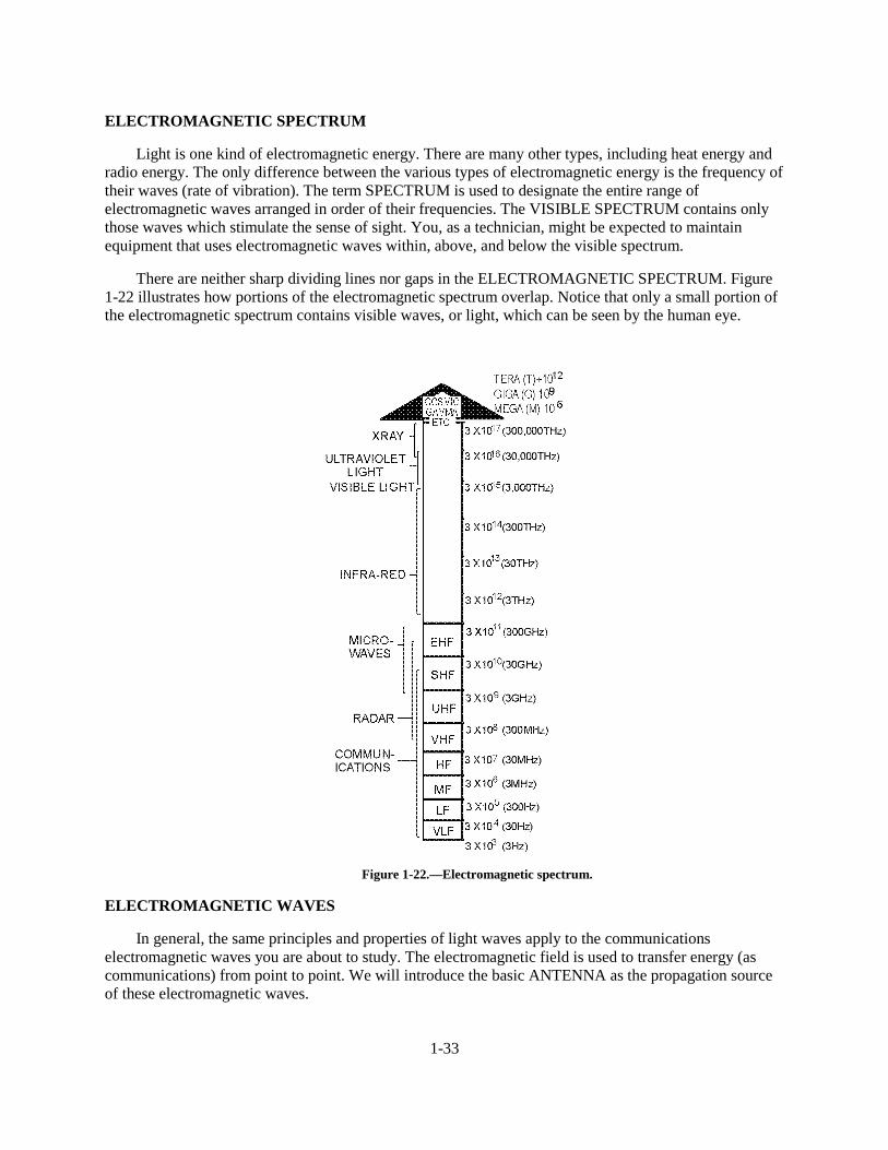
1-33
ELECTROMAGNETIC SPECTRUM
Light is one kind of electromagnetic energy. There are many other types, including heat energy andradio energy. The only difference between the various types of electromagnetic energy is the frequency oftheir waves (rate of vibration). The term SPECTRUM is used to designate the entire range ofelectromagnetic waves arranged in order of their frequencies. The VISIBLE SPECTRUM contains onlythose waves which stimulate the sense of sight. You, as a technician, might be expected to maintainequipment that uses electromagnetic waves within, above, and below the visible spectrum.
There are neither sharp dividing lines nor gaps in the ELECTROMAGNETIC SPECTRUM. Figure1-22 illustrates how portions of the electromagnetic spectrum overlap. Notice that only a small portion ofthe electromagnetic spectrum contains visible waves, or light, which can be seen by the human eye.
Figure 1-22.—Electromagnetic spectrum.
ELECTROMAGNETIC WAVES
In general, the same principles and properties of light waves apply to the communicationselectromagnetic waves you are about to study. The electromagnetic field is used to transfer energy (ascommunications) from point to point. We will introduce the basic ANTENNA as the propagation sourceof these electromagnetic waves.
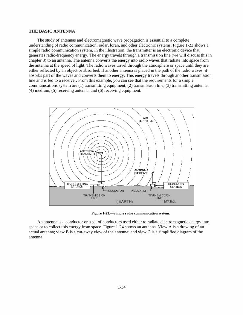
1-34
THE BASIC ANTENNA
The study of antennas and electromagnetic wave propagation is essential to a completeunderstanding of radio communication, radar, loran, and other electronic systems. Figure 1-23 shows asimple radio communication system. In the illustration, the transmitter is an electronic device thatgenerates radio-frequency energy. The energy travels through a transmission line (we will discuss this inchapter 3) to an antenna. The antenna converts the energy into radio waves that radiate into space fromthe antenna at the speed of light. The radio waves travel through the atmosphere or space until they areeither reflected by an object or absorbed. If another antenna is placed in the path of the radio waves, itabsorbs part of the waves and converts them to energy. This energy travels through another transmissionline and is fed to a receiver. From this example, you can see that the requirements for a simplecommunications system are (1) transmitting equipment, (2) transmission line, (3) transmitting antenna,(4) medium, (5) receiving antenna, and (6) receiving equipment.
Figure 1-23.—Simple radio communication system.
An antenna is a conductor or a set of conductors used either to radiate electromagnetic energy intospace or to collect this energy from space. Figure 1-24 shows an antenna. View A is a drawing of anactual antenna; view B is a cut-away view of the antenna; and view C is a simplified diagram of theantenna.
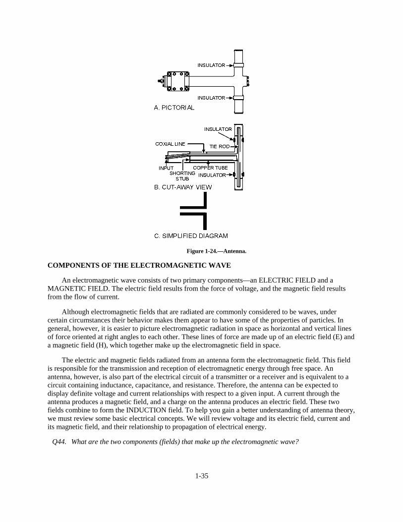
1-35
Figure 1-24.—Antenna.
COMPONENTS OF THE ELECTROMAGNETIC WAVE
An electromagnetic wave consists of two primary components—an ELECTRIC FIELD and aMAGNETIC FIELD. The electric field results from the force of voltage, and the magnetic field resultsfrom the flow of current.
Although electromagnetic fields that are radiated are commonly considered to be waves, undercertain circumstances their behavior makes them appear to have some of the properties of particles. Ingeneral, however, it is easier to picture electromagnetic radiation in space as horizontal and vertical linesof force oriented at right angles to each other. These lines of force are made up of an electric field (E) anda magnetic field (H), which together make up the electromagnetic field in space.
The electric and magnetic fields radiated from an antenna form the electromagnetic field. This fieldis responsible for the transmission and reception of electromagnetic energy through free space. Anantenna, however, is also part of the electrical circuit of a transmitter or a receiver and is equivalent to acircuit containing inductance, capacitance, and resistance. Therefore, the antenna can be expected todisplay definite voltage and current relationships with respect to a given input. A current through theantenna produces a magnetic field, and a charge on the antenna produces an electric field. These twofields combine to form the INDUCTION field. To help you gain a better understanding of antenna theory,we must review some basic electrical concepts. We will review voltage and its electric field, current andits magnetic field, and their relationship to propagation of electrical energy.
Q44. What are the two components (fields) that make up the electromagnetic wave?
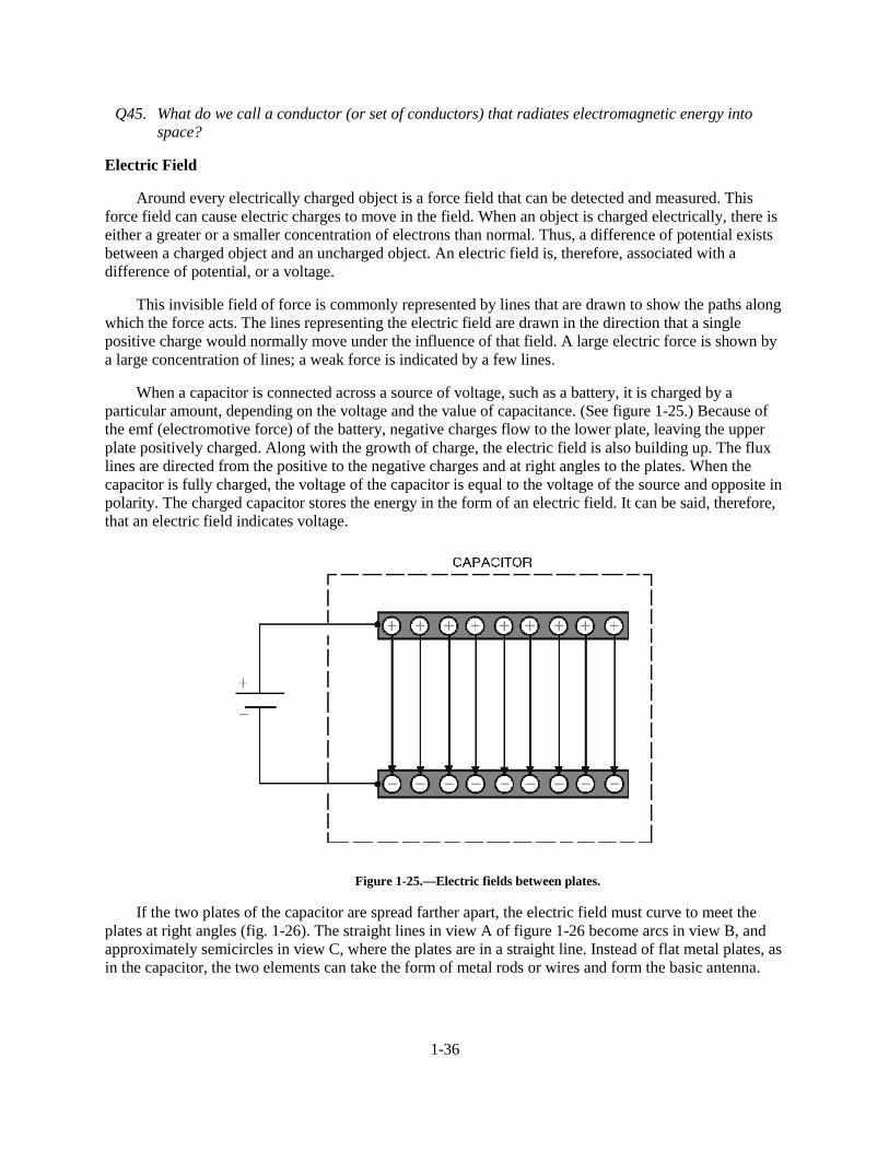
1-36
Q45. What do we call a conductor (or set of conductors) that radiates electromagnetic energy intospace?
Electric Field
Around every electrically charged object is a force field that can be detected and measured. Thisforce field can cause electric charges to move in the field. When an object is charged electrically, there iseither a greater or a smaller concentration of electrons than normal. Thus, a difference of potential existsbetween a charged object and an uncharged object. An electric field is, therefore, associated with adifference of potential, or a voltage.
This invisible field of force is commonly represented by lines that are drawn to show the paths alongwhich the force acts. The lines representing the electric field are drawn in the direction that a singlepositive charge would normally move under the influence of that field. A large electric force is shown bya large concentration of lines; a weak force is indicated by a few lines.
When a capacitor is connected across a source of voltage, such as a battery, it is charged by aparticular amount, depending on the voltage and the value of capacitance. (See figure 1-25.) Because ofthe emf (electromotive force) of the battery, negative charges flow to the lower plate, leaving the upperplate positively charged. Along with the growth of charge, the electric field is also building up. The fluxlines are directed from the positive to the negative charges and at right angles to the plates. When thecapacitor is fully charged, the voltage of the capacitor is equal to the voltage of the source and opposite inpolarity. The charged capacitor stores the energy in the form of an electric field. It can be said, therefore,that an electric field indicates voltage.
Figure 1-25.—Electric fields between plates.
If the two plates of the capacitor are spread farther apart, the electric field must curve to meet theplates at right angles (fig. 1-26). The straight lines in view A of figure 1-26 become arcs in view B, andapproximately semicircles in view C, where the plates are in a straight line. Instead of flat metal plates, asin the capacitor, the two elements can take the form of metal rods or wires and form the basic antenna.
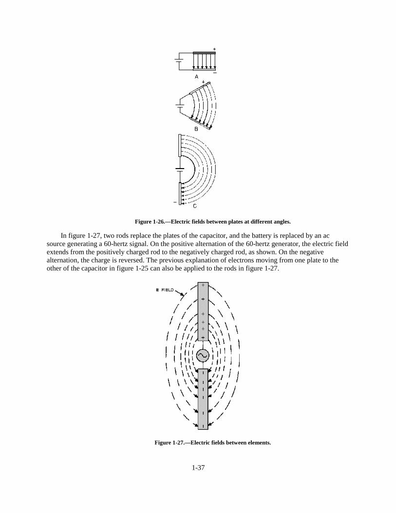
1-37
Figure 1-26.—Electric fields between plates at different angles.
In figure 1-27, two rods replace the plates of the capacitor, and the battery is replaced by an acsource generating a 60-hertz signal. On the positive alternation of the 60-hertz generator, the electric fieldextends from the positively charged rod to the negatively charged rod, as shown. On the negativealternation, the charge is reversed. The previous explanation of electrons moving from one plate to theother of the capacitor in figure 1-25 can also be applied to the rods in figure 1-27.
Figure 1-27.—Electric fields between elements.
1-38
The polarity of charges and the direction of the electric fields will reverse polarity and directionperiodically at the frequency of the voltage source. The electric field will build up from zero to maximumin one direction and then collapse back to zero. Next, the field will build up to maximum in the oppositedirection and then collapse back to zero. This complete reversal occurs during a single cycle of the sourcevoltage. The HALF-WAVE DIPOLE ANTENNA (two separate rods in line as illustrated in figure 1-27)is the fundamental element normally used as a starting point of reference in any discussion concerning theradiation of electromagnetic energy into space. If rf energy from the ac generator (or transmitter) issupplied to the element of an antenna, the voltage across the antenna lags the current by 90 degrees. Theantenna acts as if it were a capacitor.
Magnetic Field
When current flows through a conductor, a magnetic field is set up in the area surrounding theconductor. In fact, any moving electrical charge will create a magnetic field. The magnetic field is aregion in space where a magnetic force can be detected and measured. There are two other fieldsinvolved—an INDUCTION FIELD, which exists close to the conductor carrying the current, and theRADIATION FIELD, which becomes detached from the current-carrying rod and travels through space.
To represent the magnetic field, lines of force are again used to illustrate the energy. Magnetic linesare not drawn between the rods, nor between high- and low-potential points, as the E lines that werediscussed earlier. Magnetic lines are created by the flow of current rather than the force of voltage. Themagnetic lines of force, therefore, are drawn at right angles to the direction of current flow.
The magnetic fields that are set up around two parallel rods, as shown in figure 1-28 view A, are inmaximum opposition. Rod 1 contains a current flowing from the generator, while rod 2 contains a currentflowing toward the generator. As a result, the direction of the magnetic field surrounding rod 1 is oppositethe direction of the magnetic field surrounding rod 2. This will cause cancellation of part or all of bothmagnetic fields with a resultant decrease in radiation of the electromagnetic energy. View B illustrates thefact that if the far ends of rods 1 and 2 are separated from each other while the rods are still connected tothe generator at the near ends, more space, and consequently less opposition, will occur between themagnetic fields of the two rods. View C illustrates the fact that placing the rods in line makes the currentsthrough both rods flow in the same direction. Therefore, the two magnetic fields are in the same direction;thus, maximum electromagnetic radiation into space can be obtained.
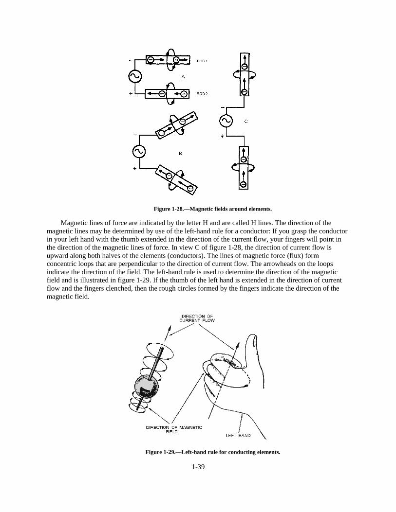
1-39
Figure 1-28.—Magnetic fields around elements.
Magnetic lines of force are indicated by the letter H and are called H lines. The direction of themagnetic lines may be determined by use of the left-hand rule for a conductor: If you grasp the conductorin your left hand with the thumb extended in the direction of the current flow, your fingers will point inthe direction of the magnetic lines of force. In view C of figure 1-28, the direction of current flow isupward along both halves of the elements (conductors). The lines of magnetic force (flux) formconcentric loops that are perpendicular to the direction of current flow. The arrowheads on the loopsindicate the direction of the field. The left-hand rule is used to determine the direction of the magneticfield and is illustrated in figure 1-29. If the thumb of the left hand is extended in the direction of currentflow and the fingers clenched, then the rough circles formed by the fingers indicate the direction of themagnetic field.
Figure 1-29.—Left-hand rule for conducting elements.
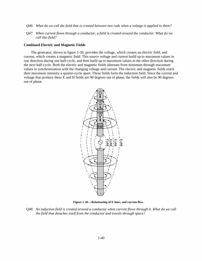
1-40
Q46. What do we call the field that is created between two rods when a voltage is applied to them?
Q47. When current flows through a conductor, a field is created around the conductor. What do wecall this field?
Combined Electric and Magnetic Fields
The generator, shown in figure 1-30, provides the voltage, which creates an electric field, andcurrent, which creates a magnetic field. This source voltage and current build up to maximum values inone direction during one half-cycle, and then build up to maximum values in the other direction duringthe next half-cycle. Both the electric and magnetic fields alternate from minimum through maximumvalues in synchronization with the changing voltage and current. The electric and magnetic fields reachtheir maximum intensity a quarter-cycle apart. These fields form the induction field. Since the current andvoltage that produce these E and H fields are 90 degrees out of phase, the fields will also be 90 degreesout of phase.
Figure 1-30.—Relationship of E-lines, and current flow.
Q48. An induction field is created around a conductor when current flows through it. What do we callthe field that detaches itself from the conductor and travels through space?
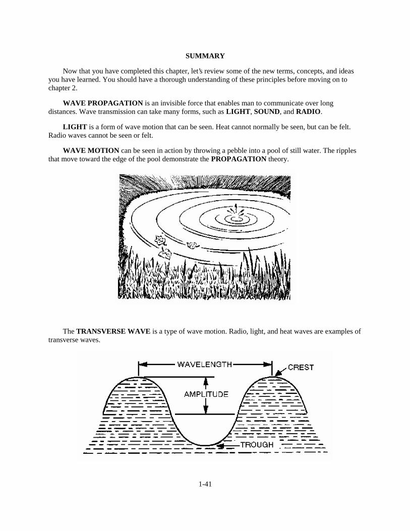
1-41
SUMMARY
Now that you have completed this chapter, let’s review some of the new terms, concepts, and ideasyou have learned. You should have a thorough understanding of these principles before moving on tochapter 2.
WAVE PROPAGATION is an invisible force that enables man to communicate over longdistances. Wave transmission can take many forms, such as LIGHT, SOUND, and RADIO.
LIGHT is a form of wave motion that can be seen. Heat cannot normally be seen, but can be felt.Radio waves cannot be seen or felt.
WAVE MOTION can be seen in action by throwing a pebble into a pool of still water. The ripplesthat move toward the edge of the pool demonstrate the PROPAGATION theory.
The TRANSVERSE WAVE is a type of wave motion. Radio, light, and heat waves are examples oftransverse waves.
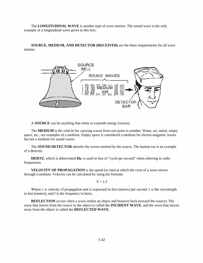
1-42
The LONGITUDINAL WAVE is another type of wave motion. The sound wave is the onlyexample of a longitudinal wave given in this text.
SOURCE, MEDIUM, AND DETECTOR (RECEIVER) are the three requirements for all wavemotion.
A SOURCE can be anything that emits or expends energy (waves).
The MEDIUM is the vehicle for carrying waves from one point to another. Water, air, metal, emptyspace, etc., are examples of a medium. Empty space is considered a medium for electro-magnetic wavesbut not a medium for sound waves.
The SOUND DETECTOR absorbs the waves emitted by the source. The human ear is an exampleof a detector.
HERTZ, which is abbreviated Hz, is used in lieu of "cycle per second" when referring to radiofrequencies.
VELOCITY OF PROPAGATION is the speed (or rate) at which the crest of a wave movesthrough a medium. Velocity can be calculated by using the formula:
9� � �I
:KHUH�Y�LV�YHORFLW\�RI�SURSDJDWLRQ�DQG�LV�H[SUHVVHG�LQ�IHHW��PHWHUV��SHU�VHFRQG�� �LV�WKH�ZDYHOHQJWKin feet (meters), and f is the frequency in hertz.
REFLECTION occurs when a wave strikes an object and bounces back (toward the source). Thewave that moves from the source to the object is called the INCIDENT WAVE, and the wave that movesaway from the object is called the REFLECTED WAVE.
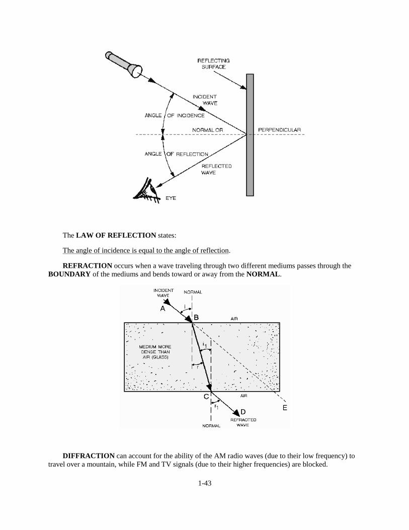
1-43
The LAW OF REFLECTION states:
The angle of incidence is equal to the angle of reflection.
REFRACTION occurs when a wave traveling through two different mediums passes through theBOUNDARY of the mediums and bends toward or away from the NORMAL.
DIFFRACTION can account for the ability of the AM radio waves (due to their low frequency) totravel over a mountain, while FM and TV signals (due to their higher frequencies) are blocked.
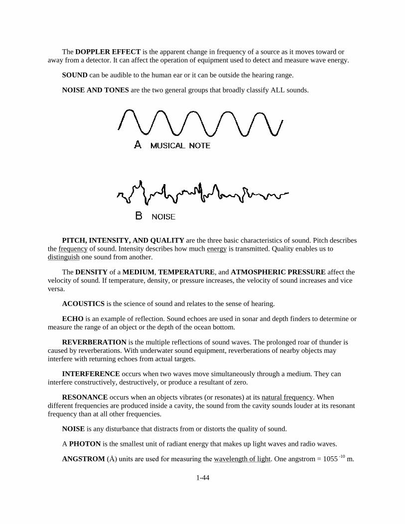
1-44
The DOPPLER EFFECT is the apparent change in frequency of a source as it moves toward oraway from a detector. It can affect the operation of equipment used to detect and measure wave energy.
SOUND can be audible to the human ear or it can be outside the hearing range.
NOISE AND TONES are the two general groups that broadly classify ALL sounds.
PITCH, INTENSITY, AND QUALITY are the three basic characteristics of sound. Pitch describesthe frequency of sound. Intensity describes how much energy is transmitted. Quality enables us todistinguish one sound from another.
The DENSITY of a MEDIUM, TEMPERATURE, and ATMOSPHERIC PRESSURE affect thevelocity of sound. If temperature, density, or pressure increases, the velocity of sound increases and viceversa.
ACOUSTICS is the science of sound and relates to the sense of hearing.
ECHO is an example of reflection. Sound echoes are used in sonar and depth finders to determine ormeasure the range of an object or the depth of the ocean bottom.
REVERBERATION is the multiple reflections of sound waves. The prolonged roar of thunder iscaused by reverberations. With underwater sound equipment, reverberations of nearby objects mayinterfere with returning echoes from actual targets.
INTERFERENCE occurs when two waves move simultaneously through a medium. They caninterfere constructively, destructively, or produce a resultant of zero.
RESONANCE occurs when an objects vibrates (or resonates) at its natural frequency. Whendifferent frequencies are produced inside a cavity, the sound from the cavity sounds louder at its resonantfrequency than at all other frequencies.
NOISE is any disturbance that distracts from or distorts the quality of sound.
A PHOTON is the smallest unit of radiant energy that makes up light waves and radio waves.
ANGSTROM ( ��XQLWV�DUH�XVHG�IRU�PHDVXULQJ�WKH�wavelength of light. One angstrom = 1055 -10 m.
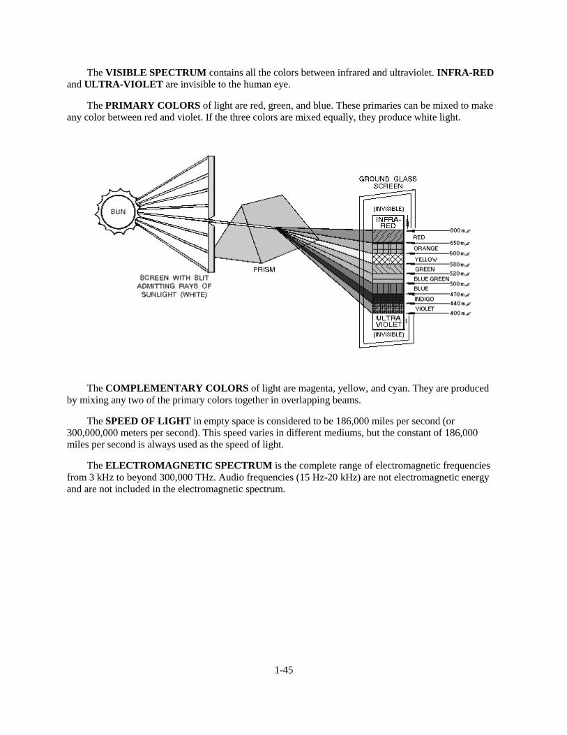
1-45
The VISIBLE SPECTRUM contains all the colors between infrared and ultraviolet. INFRA-REDand ULTRA-VIOLET are invisible to the human eye.
The PRIMARY COLORS of light are red, green, and blue. These primaries can be mixed to makeany color between red and violet. If the three colors are mixed equally, they produce white light.
The COMPLEMENTARY COLORS of light are magenta, yellow, and cyan. They are producedby mixing any two of the primary colors together in overlapping beams.
The SPEED OF LIGHT in empty space is considered to be 186,000 miles per second (or300,000,000 meters per second). This speed varies in different mediums, but the constant of 186,000miles per second is always used as the speed of light.
The ELECTROMAGNETIC SPECTRUM is the complete range of electromagnetic frequenciesfrom 3 kHz to beyond 300,000 THz. Audio frequencies (15 Hz-20 kHz) are not electromagnetic energyand are not included in the electromagnetic spectrum.
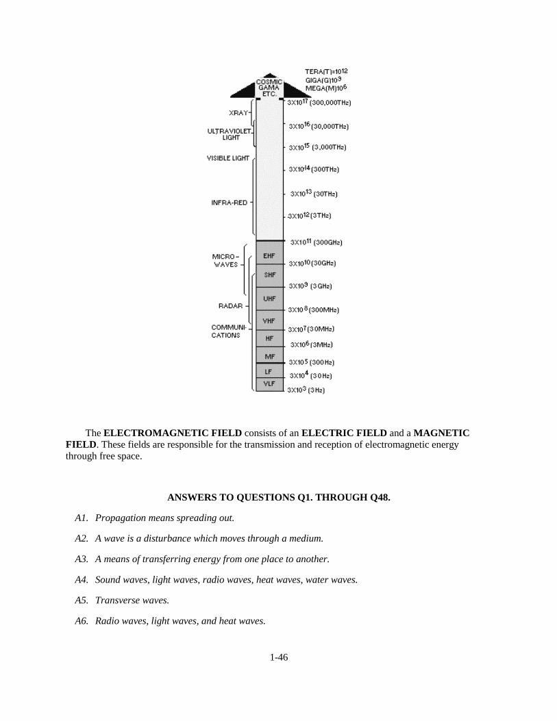
1-46
The ELECTROMAGNETIC FIELD consists of an ELECTRIC FIELD and a MAGNETICFIELD. These fields are responsible for the transmission and reception of electromagnetic energythrough free space.
ANSWERS TO QUESTIONS Q1. THROUGH Q48.
A1. Propagation means spreading out.
A2. A wave is a disturbance which moves through a medium.
A3. A means of transferring energy from one place to another.
A4. Sound waves, light waves, radio waves, heat waves, water waves.
A5. Transverse waves.
A6. Radio waves, light waves, and heat waves.
1-47
A7. A sound wave.
A8. A source, medium, and detector (receiver).
A9. A sequence of events, such as the positive and negative alternation of electrical current.
A10. The space occupied by one cycle of a radio wave at any given instant.
A11. The law of reflection states: The angle of incidence is equal to the angle of reflection.
A12. When the incident wave is nearly parallel with the surface.
A13. When the incident wave is perpendicular to the surface. Also a dull (or black) surface reflects verylittle regardless of the angle.
A14. The density of the two mediums, and the velocity of the waves.
A15. The Doppler effect.
A16. Sonics.
A17. No. The average human ear cannot hear all sounds in the infrasonic and ultrasonic regions.
A18. An amplifier.
A19. A source, medium, and detector (receiver).
A20. Noise and tones.
A21. Pitch, intensity, and quality.
A22. 20 Hz to 20 kHz.
A23. The amount of energy transmitted from a source.
A24. Quality.
A25. Velocity increases as density decreases and temperature increases.
A26. Acoustics.
A27. Echo.
A28. Reverberation.
A29. Resonance.
A30. Noise.
A31. Mechanical, electrical, and chemical.
A32. A photon.
A33. Angstrom unit.
A34. Red, green and blue.

2-1
CHAPTER 2
RADIO WAVE PROPAGATION
LEARNING OBJECTIVES
Upon completion of this unit, you should be able to:
1. State what the electromagnetic field is and what components make up the electromagnetic field.
2. State the difference between the induction field and the radiation field.
3. State what radio waves are.
4. List the components of a radio wave and define the terms cycle, frequency, harmonics, period, wavelength, and velocity as applied to radio wave propagation.
5. Compute the wavelength of radio waves.
6. State how radio waves are polarized, vertically and horizontally.
7. State what reflection, refraction, and diffraction are as applied to radio waves.
8. State what influence the Earth's atmosphere has on radio waves and list the different layers of the Earth's atmosphere.
9. Identify a ground wave, a sky wave, and state the effects of the ionosphere on the sky wave.
10. Identify the structure of the ionosphere.
11. Define density of layer, frequency, angle of incidence, skip distance, and skip zone.
12. Describe propagation paths.
13. Describe fading, multipath fading, and selective fading. Describe propagation paths.
14. State how transmission losses affect radio wave propagation.
15. State how electromagnetic interference, man-made/natural interference, and ionospheric disturbances affect radio wave propagation. State how transmission losses affect radio wave propagation.
16. Identify variations in the ionosphere.
17. Identify the maximum, optimum, and lowest usable frequencies of radio waves.
18. State what temperature inversion is, how frequency predictions are made, and how weather affects frequency.
19. State what tropospheric scatter is and how it affects radio wave propagation.
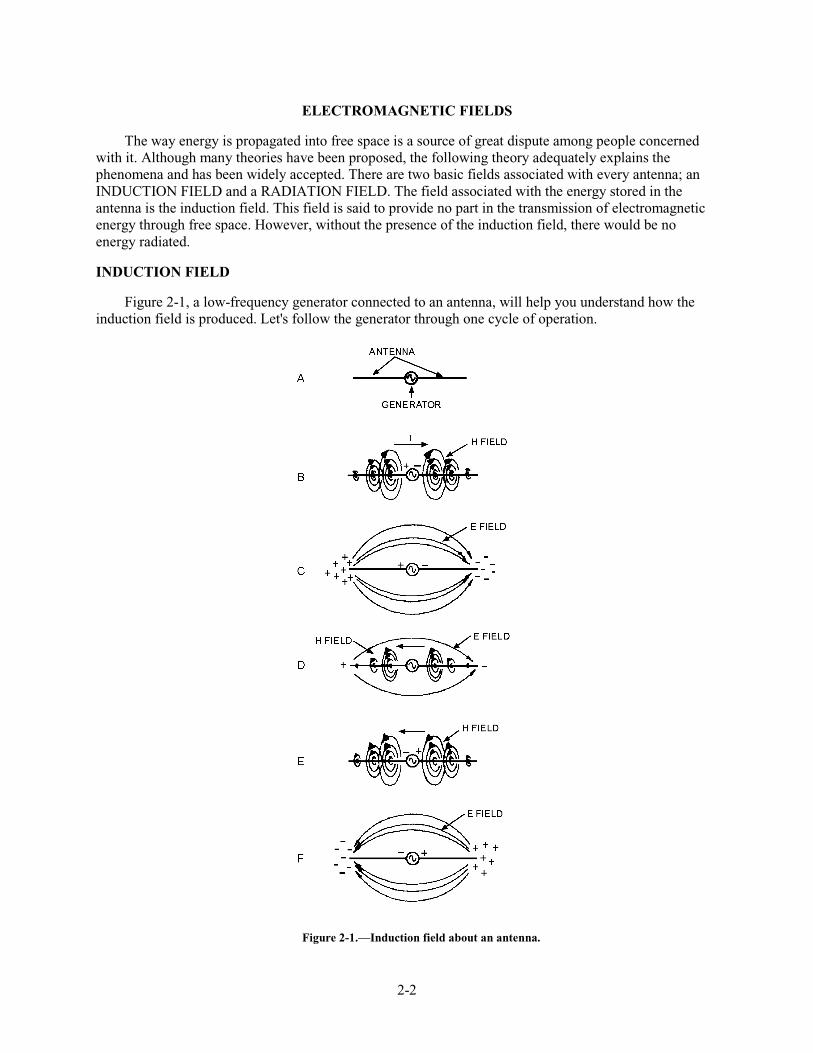
2-2
ELECTROMAGNETIC FIELDS
The way energy is propagated into free space is a source of great dispute among people concerned with it. Although many theories have been proposed, the following theory adequately explains the phenomena and has been widely accepted. There are two basic fields associated with every antenna; an INDUCTION FIELD and a RADIATION FIELD. The field associated with the energy stored in the antenna is the induction field. This field is said to provide no part in the transmission of electromagnetic energy through free space. However, without the presence of the induction field, there would be no energy radiated.
INDUCTION FIELD
Figure 2-1, a low-frequency generator connected to an antenna, will help you understand how the induction field is produced. Let's follow the generator through one cycle of operation.
Figure 2-1.—Induction field about an antenna.
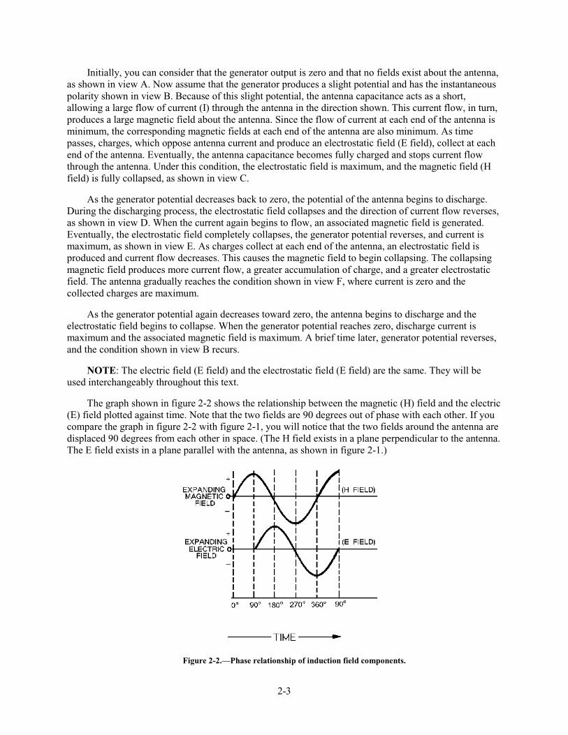
2-3
Initially, you can consider that the generator output is zero and that no fields exist about the antenna, as shown in view A. Now assume that the generator produces a slight potential and has the instantaneous polarity shown in view B. Because of this slight potential, the antenna capacitance acts as a short, allowing a large flow of current (I) through the antenna in the direction shown. This current flow, in turn, produces a large magnetic field about the antenna. Since the flow of current at each end of the antenna is minimum, the corresponding magnetic fields at each end of the antenna are also minimum. As time passes, charges, which oppose antenna current and produce an electrostatic field (E field), collect at each end of the antenna. Eventually, the antenna capacitance becomes fully charged and stops current flow through the antenna. Under this condition, the electrostatic field is maximum, and the magnetic field (H field) is fully collapsed, as shown in view C.
As the generator potential decreases back to zero, the potential of the antenna begins to discharge. During the discharging process, the electrostatic field collapses and the direction of current flow reverses, as shown in view D. When the current again begins to flow, an associated magnetic field is generated. Eventually, the electrostatic field completely collapses, the generator potential reverses, and current is maximum, as shown in view E. As charges collect at each end of the antenna, an electrostatic field is produced and current flow decreases. This causes the magnetic field to begin collapsing. The collapsing magnetic field produces more current flow, a greater accumulation of charge, and a greater electrostatic field. The antenna gradually reaches the condition shown in view F, where current is zero and the collected charges are maximum.
As the generator potential again decreases toward zero, the antenna begins to discharge and the electrostatic field begins to collapse. When the generator potential reaches zero, discharge current is maximum and the associated magnetic field is maximum. A brief time later, generator potential reverses, and the condition shown in view B recurs.
NOTE: The electric field (E field) and the electrostatic field (E field) are the same. They will be used interchangeably throughout this text.
The graph shown in figure 2-2 shows the relationship between the magnetic (H) field and the electric (E) field plotted against time. Note that the two fields are 90 degrees out of phase with each other. If you compare the graph in figure 2-2 with figure 2-1, you will notice that the two fields around the antenna are displaced 90 degrees from each other in space. (The H field exists in a plane perpendicular to the antenna. The E field exists in a plane parallel with the antenna, as shown in figure 2-1.)
Figure 2-2.—Phase relationship of induction field components.
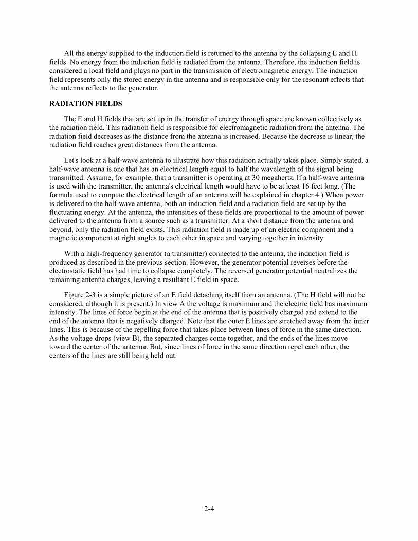
2-4
All the energy supplied to the induction field is returned to the antenna by the collapsing E and H fields. No energy from the induction field is radiated from the antenna. Therefore, the induction field is considered a local field and plays no part in the transmission of electromagnetic energy. The induction field represents only the stored energy in the antenna and is responsible only for the resonant effects that the antenna reflects to the generator.
RADIATION FIELDS
The E and H fields that are set up in the transfer of energy through space are known collectively as the radiation field. This radiation field is responsible for electromagnetic radiation from the antenna. The radiation field decreases as the distance from the antenna is increased. Because the decrease is linear, the radiation field reaches great distances from the antenna.
Let's look at a half-wave antenna to illustrate how this radiation actually takes place. Simply stated, a half-wave antenna is one that has an electrical length equal to half the wavelength of the signal being transmitted. Assume, for example, that a transmitter is operating at 30 megahertz. If a half-wave antenna is used with the transmitter, the antenna's electrical length would have to be at least 16 feet long. (The formula used to compute the electrical length of an antenna will be explained in chapter 4.) When power is delivered to the half-wave antenna, both an induction field and a radiation field are set up by the fluctuating energy. At the antenna, the intensities of these fields are proportional to the amount of power delivered to the antenna from a source such as a transmitter. At a short distance from the antenna and beyond, only the radiation field exists. This radiation field is made up of an electric component and a magnetic component at right angles to each other in space and varying together in intensity.
With a high-frequency generator (a transmitter) connected to the antenna, the induction field is produced as described in the previous section. However, the generator potential reverses before the electrostatic field has had time to collapse completely. The reversed generator potential neutralizes the remaining antenna charges, leaving a resultant E field in space.
Figure 2-3 is a simple picture of an E field detaching itself from an antenna. (The H field will not be considered, although it is present.) In view A the voltage is maximum and the electric field has maximum intensity. The lines of force begin at the end of the antenna that is positively charged and extend to the end of the antenna that is negatively charged. Note that the outer E lines are stretched away from the inner lines. This is because of the repelling force that takes place between lines of force in the same direction. As the voltage drops (view B), the separated charges come together, and the ends of the lines move toward the center of the antenna. But, since lines of force in the same direction repel each other, the centers of the lines are still being held out.
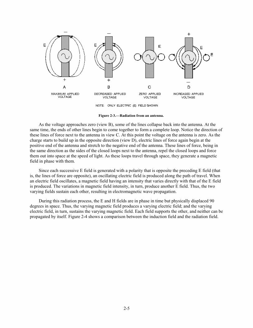
2-5
Figure 2-3.—Radiation from an antenna.
As the voltage approaches zero (view B), some of the lines collapse back into the antenna. At the same time, the ends of other lines begin to come together to form a complete loop. Notice the direction of these lines of force next to the antenna in view C. At this point the voltage on the antenna is zero. As the charge starts to build up in the opposite direction (view D), electric lines of force again begin at the positive end of the antenna and stretch to the negative end of the antenna. These lines of force, being in the same direction as the sides of the closed loops next to the antenna, repel the closed loops and force them out into space at the speed of light. As these loops travel through space, they generate a magnetic field in phase with them.
Since each successive E field is generated with a polarity that is opposite the preceding E field (that is, the lines of force are opposite), an oscillating electric field is produced along the path of travel. When an electric field oscillates, a magnetic field having an intensity that varies directly with that of the E field is produced. The variations in magnetic field intensity, in turn, produce another E field. Thus, the two varying fields sustain each other, resulting in electromagnetic wave propagation.
During this radiation process, the E and H fields are in phase in time but physically displaced 90 degrees in space. Thus, the varying magnetic field produces a varying electric field; and the varying electric field, in turn, sustains the varying magnetic field. Each field supports the other, and neither can be propagated by itself. Figure 2-4 shows a comparison between the induction field and the radiation field.
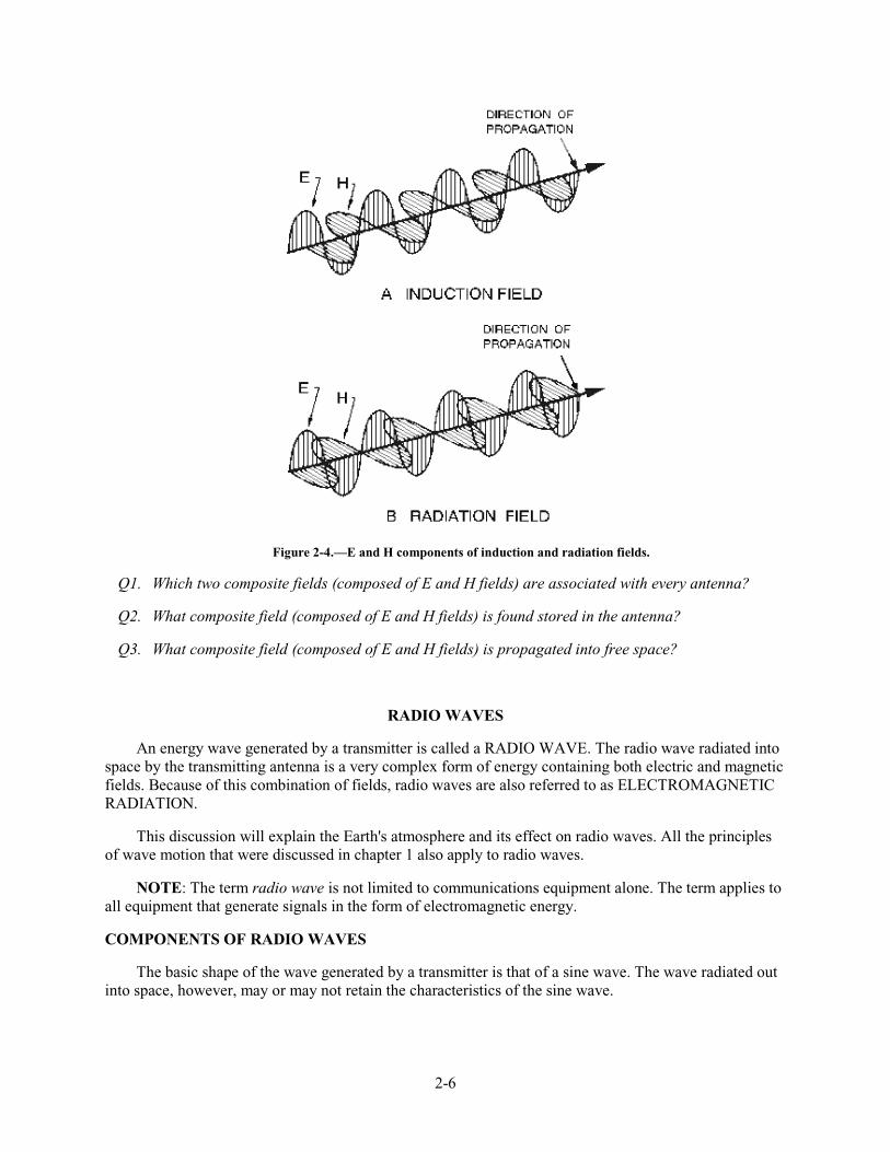
2-6
Figure 2-4.—E and H components of induction and radiation fields.
Q1. Which two composite fields (composed of E and H fields) are associated with every antenna?
Q2. What composite field (composed of E and H fields) is found stored in the antenna?
Q3. What composite field (composed of E and H fields) is propagated into free space?
RADIO WAVES
An energy wave generated by a transmitter is called a RADIO WAVE. The radio wave radiated into space by the transmitting antenna is a very complex form of energy containing both electric and magnetic fields. Because of this combination of fields, radio waves are also referred to as ELECTROMAGNETIC RADIATION.
This discussion will explain the Earth's atmosphere and its effect on radio waves. All the principles of wave motion that were discussed in chapter 1 also apply to radio waves.
NOTE: The term radio wave is not limited to communications equipment alone. The term applies to all equipment that generate signals in the form of electromagnetic energy.
COMPONENTS OF RADIO WAVES
The basic shape of the wave generated by a transmitter is that of a sine wave. The wave radiated out into space, however, may or may not retain the characteristics of the sine wave.
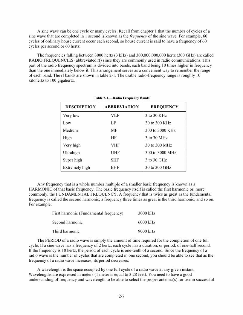
2-7
A sine wave can be one cycle or many cycles. Recall from chapter 1 that the number of cycles of a sine wave that are completed in 1 second is known as the frequency of the sine wave. For example, 60 cycles of ordinary house current occur each second, so house current is said to have a frequency of 60 cycles per second or 60 hertz.
The frequencies falling between 3000 hertz (3 kHz) and 300,000,000,000 hertz (300 GHz) are called RADIO FREQUENCIES (abbreviated rf) since they are commonly used in radio communications. This part of the radio frequency spectrum is divided into bands, each band being 10 times higher in frequency than the one immediately below it. This arrangement serves as a convenient way to remember the range of each band. The rf bands are shown in table 2-1. The usable radio-frequency range is roughly 10 kilohertz to 100 gigahertz.
Table 2-1.—Radio Frequency Bands
DESCRIPTION ABBREVIATION FREQUENCY
Very low VLF 3 to 30 KHz
Low LF 30 to 300 KHz
Medium MF 300 to 3000 KHz
High HF 3 to 30 MHz
Very high VHF 30 to 300 MHz
Ultrahigh UHF 300 to 3000 MHz
Super high SHF 3 to 30 GHz
Extremely high EHF 30 to 300 GHz
Any frequency that is a whole number multiple of a smaller basic frequency is known as a HARMONIC of that basic frequency. The basic frequency itself is called the first harmonic or, more commonly, the FUNDAMENTAL FREQUENCY. A frequency that is twice as great as the fundamental frequency is called the second harmonic; a frequency three times as great is the third harmonic; and so on. For example:
First harmonic (Fundamental frequency) 3000 kHz
Second harmonic 6000 kHz
Third harmonic 9000 kHz
The PERIOD of a radio wave is simply the amount of time required for the completion of one full cycle. If a sine wave has a frequency of 2 hertz, each cycle has a duration, or period, of one-half second. If the frequency is 10 hertz, the period of each cycle is one-tenth of a second. Since the frequency of a radio wave is the number of cycles that are completed in one second, you should be able to see that as the frequency of a radio wave increases, its period decreases.
A wavelength is the space occupied by one full cycle of a radio wave at any given instant. Wavelengths are expressed in meters (1 meter is equal to 3.28 feet). You need to have a good understanding of frequency and wavelength to be able to select the proper antenna(s) for use in successful
2-8
communications. The relationship between frequency, wavelength, and antennas will be discussed in chapter 4 of this module.
The velocity (or speed) of a radio wave radiated into free space by a transmitting antenna is equal to the speed of light—186,000 miles per second or 300,000,000 meters per second. Because of various factors, such as barometric pressure, humidity, molecular content, etc., radio waves travel inside the Earth's atmosphere at a speed slightly less than the speed of light. Normally, in discussions of the velocity of radio waves, the velocity referred to is the speed at which radio waves travel in free space.
The frequency of a radio wave has nothing to do with its velocity. A 5-megahertz wave travels through space at the same velocity as a 10-megahertz wave. However, the velocity of radio waves is an important factor in making wavelength-to-frequency conversions, the subject of our next discussion.
Q4. What is the term used to describe the basic frequency of a radio wave?
Q5. What is the term used to describe a whole number multiple of the basic frequency of a radio wave?
WAVELENGTH-TO-FREQUENCY CONVERSIONS
Radio waves are often referred to by their wavelength in meters rather than by frequency. For example, most people have heard commercial radio stations make announcements similar to the following: "Station WXYZ operating on 240 meters..." To tune receiving equipment that is calibrated by frequency to such a station, you must first convert the designated wavelength to its equivalent frequency.
As discussed earlier, a radio wave travels 300,000,000 meters a second (speed of light); therefore, a radio wave of 1 hertz would have traveled a distance (or wavelength) of 300,000,000 meters. Obviously then, if the frequency of the wave is increased to 2 hertz, the wavelength will be cut in half to 150,000,000 meters. This illustrates the principle that the HIGHER THE FREQUENCY, the SHORTER THE WAVELENGTH.
Wavelength-to-frequency conversions of radio waves are really quite simple because wavelength and frequency are reciprocals: Either one divided into the velocity of a radio wave yields the other. Remember, the formula for wavelength is:
The wavelength in meters divided into 300,000,000 yields the frequency of a radio wave in hertz. Likewise, the wavelength divided into 300,000 yields the frequency of a radio wave in kilohertz, and the wavelength divided into 300 yields the frequency in megahertz.
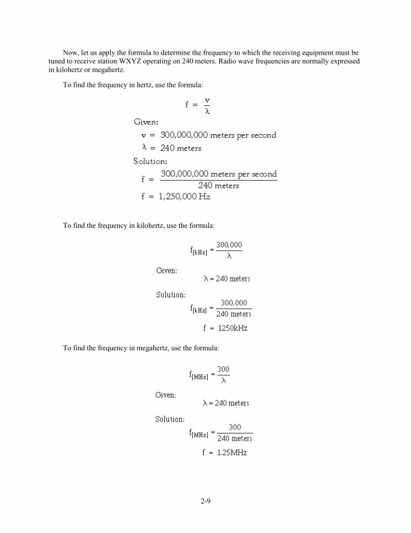
2-9
Now, let us apply the formula to determine the frequency to which the receiving equipment must be tuned to receive station WXYZ operating on 240 meters. Radio wave frequencies are normally expressed in kilohertz or megahertz.
To find the frequency in hertz, use the formula:
To find the frequency in kilohertz, use the formula:
To find the frequency in megahertz, use the formula:
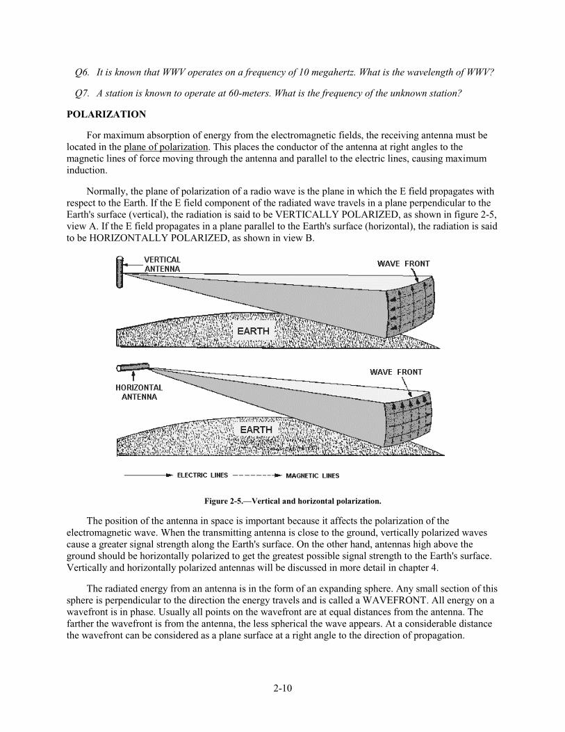
2-10
Q6. It is known that WWV operates on a frequency of 10 megahertz. What is the wavelength of WWV?
Q7. A station is known to operate at 60-meters. What is the frequency of the unknown station?
POLARIZATION
For maximum absorption of energy from the electromagnetic fields, the receiving antenna must be located in the plane of polarization. This places the conductor of the antenna at right angles to the magnetic lines of force moving through the antenna and parallel to the electric lines, causing maximum induction.
Normally, the plane of polarization of a radio wave is the plane in which the E field propagates with respect to the Earth. If the E field component of the radiated wave travels in a plane perpendicular to the Earth's surface (vertical), the radiation is said to be VERTICALLY POLARIZED, as shown in figure 2-5, view A. If the E field propagates in a plane parallel to the Earth's surface (horizontal), the radiation is said to be HORIZONTALLY POLARIZED, as shown in view B.
Figure 2-5.—Vertical and horizontal polarization.
The position of the antenna in space is important because it affects the polarization of the electromagnetic wave. When the transmitting antenna is close to the ground, vertically polarized waves cause a greater signal strength along the Earth's surface. On the other hand, antennas high above the ground should be horizontally polarized to get the greatest possible signal strength to the Earth's surface. Vertically and horizontally polarized antennas will be discussed in more detail in chapter 4.
The radiated energy from an antenna is in the form of an expanding sphere. Any small section of this sphere is perpendicular to the direction the energy travels and is called a WAVEFRONT. All energy on a wavefront is in phase. Usually all points on the wavefront are at equal distances from the antenna. The farther the wavefront is from the antenna, the less spherical the wave appears. At a considerable distance the wavefront can be considered as a plane surface at a right angle to the direction of propagation.
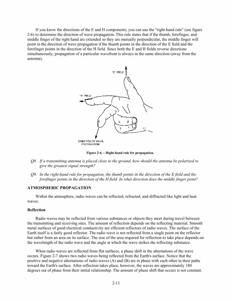
2-11
If you know the directions of the E and H components, you can use the "right-hand rule" (see figure 2-6) to determine the direction of wave propagation. This rule states that if the thumb, forefinger, and middle finger of the right hand are extended so they are mutually perpendicular, the middle finger will point in the direction of wave propagation if the thumb points in the direction of the E field and the forefinger points in the direction of the H field. Since both the E and H fields reverse directions simultaneously, propagation of a particular wavefront is always in the same direction (away from the antenna).
Figure 2-6.—Right-hand rule for propagation.
Q8. If a transmitting antenna is placed close to the ground, how should the antenna be polarized to give the greatest signal strength?
Q9. In the right-hand rule for propagation, the thumb points in the direction of the E field and the forefinger points in the direction of the H field. In what direction does the middle finger point?
ATMOSPHERIC PROPAGATION
Within the atmosphere, radio waves can be reflected, refracted, and diffracted like light and heat waves.
Reflection
Radio waves may be reflected from various substances or objects they meet during travel between the transmitting and receiving sites. The amount of reflection depends on the reflecting material. Smooth metal surfaces of good electrical conductivity are efficient reflectors of radio waves. The surface of the Earth itself is a fairly good reflector. The radio wave is not reflected from a single point on the reflector but rather from an area on its surface. The size of the area required for reflection to take place depends on the wavelength of the radio wave and the angle at which the wave strikes the reflecting substance.
When radio waves are reflected from flat surfaces, a phase shift in the alternations of the wave occurs. Figure 2-7 shows two radio waves being reflected from the Earth's surface. Notice that the positive and negative alternations of radio waves (A) and (B) are in phase with each other in their paths toward the Earth's surface. After reflection takes place, however, the waves are approximately 180 degrees out of phase from their initial relationship. The amount of phase shift that occurs is not constant.
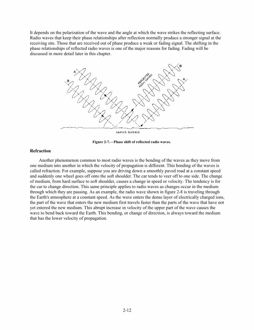
2-12
It depends on the polarization of the wave and the angle at which the wave strikes the reflecting surface. Radio waves that keep their phase relationships after reflection normally produce a stronger signal at the receiving site. Those that are received out of phase produce a weak or fading signal. The shifting in the phase relationships of reflected radio waves is one of the major reasons for fading. Fading will be discussed in more detail later in this chapter.
Figure 2-7.—Phase shift of reflected radio waves.
Refraction
Another phenomenon common to most radio waves is the bending of the waves as they move from one medium into another in which the velocity of propagation is different. This bending of the waves is called refraction. For example, suppose you are driving down a smoothly paved road at a constant speed and suddenly one wheel goes off onto the soft shoulder. The car tends to veer off to one side. The change of medium, from hard surface to soft shoulder, causes a change in speed or velocity. The tendency is for the car to change direction. This same principle applies to radio waves as changes occur in the medium through which they are passing. As an example, the radio wave shown in figure 2-8 is traveling through the Earth's atmosphere at a constant speed. As the wave enters the dense layer of electrically charged ions, the part of the wave that enters the new medium first travels faster than the parts of the wave that have not yet entered the new medium. This abrupt increase in velocity of the upper part of the wave causes the wave to bend back toward the Earth. This bending, or change of direction, is always toward the medium that has the lower velocity of propagation.
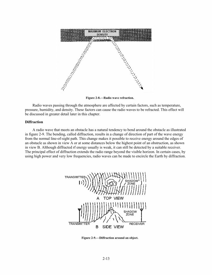
2-13
Figure 2-8.—Radio wave refraction.
Radio waves passing through the atmosphere are affected by certain factors, such as temperature, pressure, humidity, and density. These factors can cause the radio waves to be refracted. This effect will be discussed in greater detail later in this chapter.
Diffraction
A radio wave that meets an obstacle has a natural tendency to bend around the obstacle as illustrated in figure 2-9. The bending, called diffraction, results in a change of direction of part of the wave energy from the normal line-of-sight path. This change makes it possible to receive energy around the edges of an obstacle as shown in view A or at some distances below the highest point of an obstruction, as shown in view B. Although diffracted rf energy usually is weak, it can still be detected by a suitable receiver. The principal effect of diffraction extends the radio range beyond the visible horizon. In certain cases, by using high power and very low frequencies, radio waves can be made to encircle the Earth by diffraction.
Figure 2-9.—Diffraction around an object.
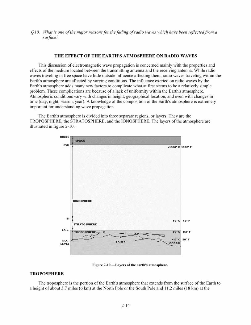
2-14
Q10. What is one of the major reasons for the fading of radio waves which have been reflected from a surface?
THE EFFECT OF THE EARTH'S ATMOSPHERE ON RADIO WAVES
This discussion of electromagnetic wave propagation is concerned mainly with the properties and effects of the medium located between the transmitting antenna and the receiving antenna. While radio waves traveling in free space have little outside influence affecting them, radio waves traveling within the Earth's atmosphere are affected by varying conditions. The influence exerted on radio waves by the Earth's atmosphere adds many new factors to complicate what at first seems to be a relatively simple problem. These complications are because of a lack of uniformity within the Earth's atmosphere. Atmospheric conditions vary with changes in height, geographical location, and even with changes in time (day, night, season, year). A knowledge of the composition of the Earth's atmosphere is extremely important for understanding wave propagation.
The Earth's atmosphere is divided into three separate regions, or layers. They are the TROPOSPHERE, the STRATOSPHERE, and the IONOSPHERE. The layers of the atmosphere are illustrated in figure 2-10.
Figure 2-10.—Layers of the earth's atmosphere.
TROPOSPHERE
The troposphere is the portion of the Earth's atmosphere that extends from the surface of the Earth to a height of about 3.7 miles (6 km) at the North Pole or the South Pole and 11.2 miles (18 km) at the
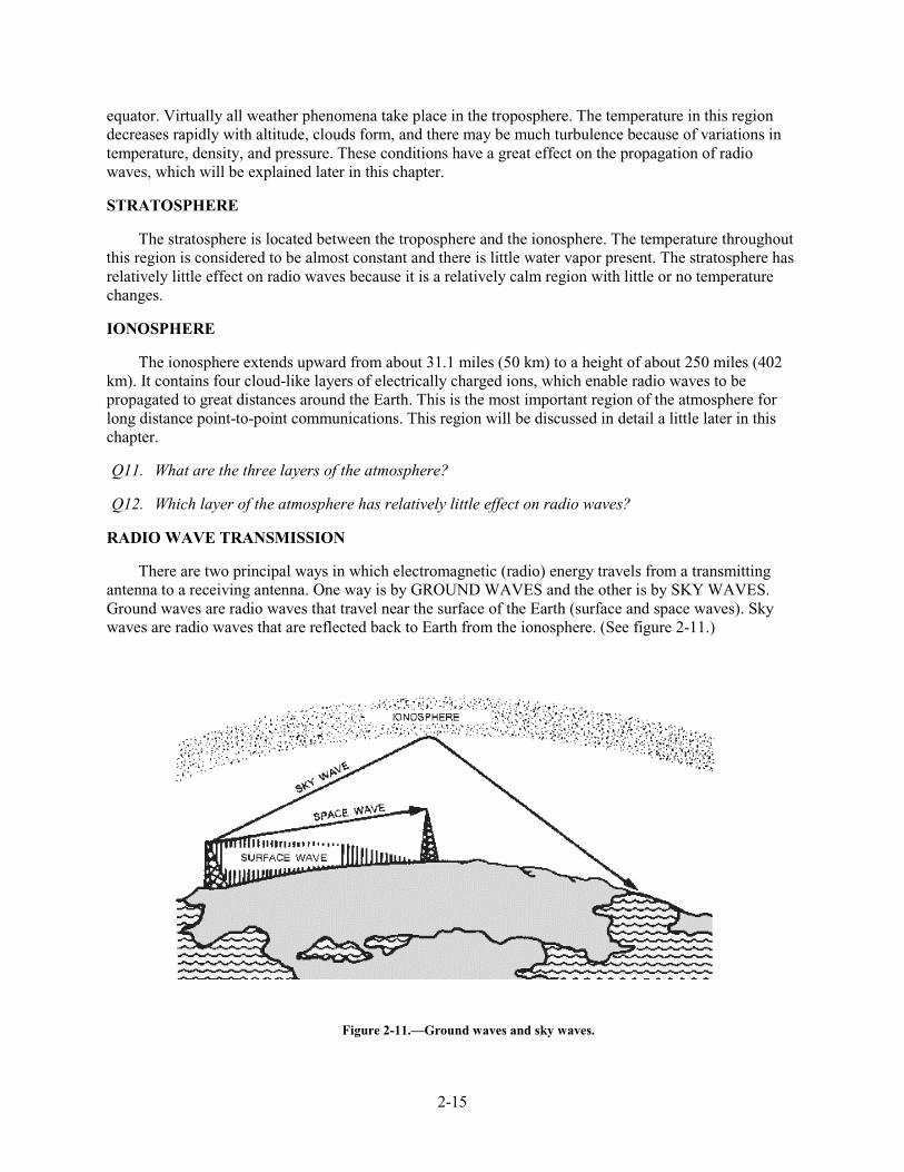
2-15
equator. Virtually all weather phenomena take place in the troposphere. The temperature in this region decreases rapidly with altitude, clouds form, and there may be much turbulence because of variations in temperature, density, and pressure. These conditions have a great effect on the propagation of radio waves, which will be explained later in this chapter.
STRATOSPHERE
The stratosphere is located between the troposphere and the ionosphere. The temperature throughout this region is considered to be almost constant and there is little water vapor present. The stratosphere has relatively little effect on radio waves because it is a relatively calm region with little or no temperature changes.
IONOSPHERE
The ionosphere extends upward from about 31.1 miles (50 km) to a height of about 250 miles (402 km). It contains four cloud-like layers of electrically charged ions, which enable radio waves to be propagated to great distances around the Earth. This is the most important region of the atmosphere for long distance point-to-point communications. This region will be discussed in detail a little later in this chapter.
Q11. What are the three layers of the atmosphere?
Q12. Which layer of the atmosphere has relatively little effect on radio waves?
RADIO WAVE TRANSMISSION
There are two principal ways in which electromagnetic (radio) energy travels from a transmitting antenna to a receiving antenna. One way is by GROUND WAVES and the other is by SKY WAVES. Ground waves are radio waves that travel near the surface of the Earth (surface and space waves). Sky waves are radio waves that are reflected back to Earth from the ionosphere. (See figure 2-11.)
Figure 2-11.—Ground waves and sky waves.

2-16
Ground Waves
The ground wave is actually composed of two separate component waves. These are known as the SURFACE WAVE and the SPACE WAVE (fig. 2-11). The determining factor in whether a ground wave component is classified as a space wave or a surface wave is simple. A surface wave travels along the surface of the Earth. A space wave travels over the surface.
SURFACE WAVE.—The surface wave reaches the receiving site by traveling along the surface of the ground as shown in figure 2-12. A surface wave can follow the contours of the Earth because of the process of diffraction. When a surface wave meets an object and the dimensions of the object do not exceed its wavelength, the wave tends to curve or bend around the object. The smaller the object, the more pronounced the diffractive action will be.
Figure 2-12.—Surface wave propagation.
As a surface wave passes over the ground, the wave induces a voltage in the Earth. The induced voltage takes energy away from the surface wave, thereby weakening, or attenuating, the wave as it moves away from the transmitting antenna. To reduce the attenuation, the amount of induced voltage must be reduced. This is done by using vertically polarized waves that minimize the extent to which the electric field of the wave is in contact with the Earth. When a surface wave is horizontally polarized, the electric field of the wave is parallel with the surface of the Earth and, therefore, is constantly in contact with it. The wave is then completely attenuated within a short distance from the transmitting site. On the other hand, when the surface wave is vertically polarized, the electric field is vertical to the Earth and merely dips into and out of the Earth's surface. For this reason, vertical polarization is vastly superior to horizontal polarization for surface wave propagation.
The attenuation that a surface wave undergoes because of induced voltage also depends on the electrical properties of the terrain over which the wave travels. The best type of surface is one that has good electrical conductivity. The better the conductivity, the less the attenuation. Table 2-2 gives the relative conductivity of various surfaces of the Earth.
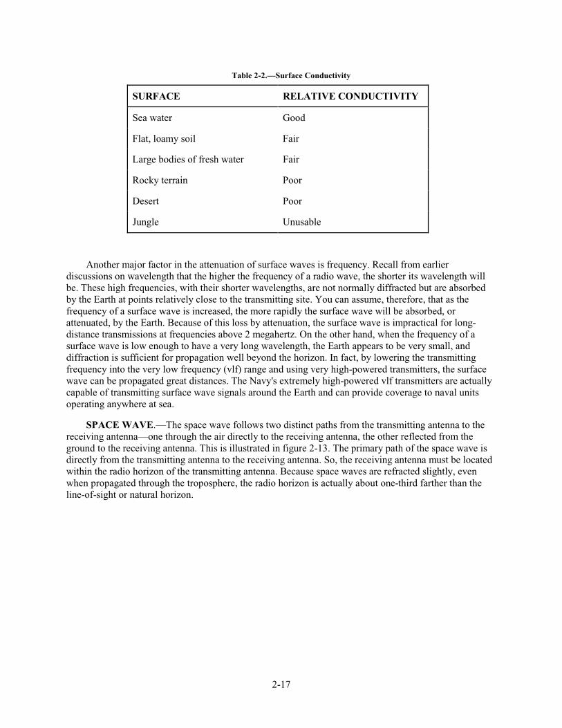
2-17
Table 2-2.—Surface Conductivity
SURFACE RELATIVE CONDUCTIVITY
Sea water Good
Flat, loamy soil Fair
Large bodies of fresh water Fair
Rocky terrain Poor
Desert Poor
Jungle Unusable
Another major factor in the attenuation of surface waves is frequency. Recall from earlier discussions on wavelength that the higher the frequency of a radio wave, the shorter its wavelength will be. These high frequencies, with their shorter wavelengths, are not normally diffracted but are absorbed by the Earth at points relatively close to the transmitting site. You can assume, therefore, that as the frequency of a surface wave is increased, the more rapidly the surface wave will be absorbed, or attenuated, by the Earth. Because of this loss by attenuation, the surface wave is impractical for long-distance transmissions at frequencies above 2 megahertz. On the other hand, when the frequency of a surface wave is low enough to have a very long wavelength, the Earth appears to be very small, and diffraction is sufficient for propagation well beyond the horizon. In fact, by lowering the transmitting frequency into the very low frequency (vlf) range and using very high-powered transmitters, the surface wave can be propagated great distances. The Navy's extremely high-powered vlf transmitters are actually capable of transmitting surface wave signals around the Earth and can provide coverage to naval units operating anywhere at sea.
SPACE WAVE.—The space wave follows two distinct paths from the transmitting antenna to the receiving antenna—one through the air directly to the receiving antenna, the other reflected from the ground to the receiving antenna. This is illustrated in figure 2-13. The primary path of the space wave is directly from the transmitting antenna to the receiving antenna. So, the receiving antenna must be located within the radio horizon of the transmitting antenna. Because space waves are refracted slightly, even when propagated through the troposphere, the radio horizon is actually about one-third farther than the line-of-sight or natural horizon.
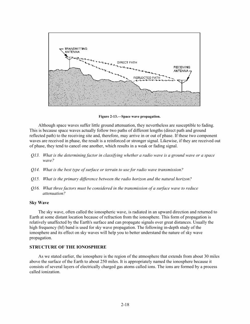
2-18
Figure 2-13.—Space wave propagation.
Although space waves suffer little ground attenuation, they nevertheless are susceptible to fading. This is because space waves actually follow two paths of different lengths (direct path and ground reflected path) to the receiving site and, therefore, may arrive in or out of phase. If these two component waves are received in phase, the result is a reinforced or stronger signal. Likewise, if they are received out of phase, they tend to cancel one another, which results in a weak or fading signal.
Q13. What is the determining factor in classifying whether a radio wave is a ground wave or a space wave?
Q14. What is the best type of surface or terrain to use for radio wave transmission?
Q15. What is the primary difference between the radio horizon and the natural horizon?
Q16. What three factors must be considered in the transmission of a surface wave to reduce attenuation?
Sky Wave
The sky wave, often called the ionospheric wave, is radiated in an upward direction and returned to Earth at some distant location because of refraction from the ionosphere. This form of propagation is relatively unaffected by the Earth's surface and can propagate signals over great distances. Usually the high frequency (hf) band is used for sky wave propagation. The following in-depth study of the ionosphere and its effect on sky waves will help you to better understand the nature of sky wave propagation.
STRUCTURE OF THE IONOSPHERE
As we stated earlier, the ionosphere is the region of the atmosphere that extends from about 30 miles above the surface of the Earth to about 250 miles. It is appropriately named the ionosphere because it consists of several layers of electrically charged gas atoms called ions. The ions are formed by a process called ionization.
2-19
Ionization
Ionization occurs when high energy ultraviolet light waves from the sun enter the ionospheric region of the atmosphere, strike a gas atom, and literally knock an electron free from its parent atom. A normal atom is electrically neutral since it contains both a positive proton in its nucleus and a negative orbiting electron. When the negative electron is knocked free from the atom, the atom becomes positively charged (called a positive ion) and remains in space along with the free electron, which is negatively charged. This process of upsetting electrical neutrality is known as IONIZATION.
The free negative electrons subsequently absorb part of the ultraviolet energy, which initially freed them from their atoms. As the ultraviolet light wave continues to produce positive ions and negative electrons, its intensity decreases because of the absorption of energy by the free electrons, and an ionized layer is formed. The rate at which ionization occurs depends on the density of atoms in the atmosphere and the intensity of the ultraviolet light wave, which varies with the activity of the sun.
Since the atmosphere is bombarded by ultraviolet light waves of different frequencies, several ionized layers are formed at different altitudes. Lower frequency ultraviolet waves penetrate the atmosphere the least; therefore, they produce ionized layers at the higher altitudes. Conversely, ultraviolet waves of higher frequencies penetrate deeper and produce layers at the lower altitudes.
An important factor in determining the density of ionized layers is the elevation angle of the sun, which changes frequently. For this reason, the height and thickness of the ionized layers vary, depending on the time of day and even the season of the year.
Recombination
Recall that the process of ionization involves ultraviolet light waves knocking electrons free from their atoms. A reverse process called RECOMBINATION occurs when the free electrons and positive ions collide with each other. Since these collisions are inevitable, the positive ions return to their original neutral atom state.
The recombination process also depends on the time of day. Between the hours of early morning and late afternoon, the rate of ionization exceeds the rate of recombination. During this period, the ionized layers reach their greatest density and exert maximum influence on radio waves. During the late afternoon and early evening hours, however, the rate of recombination exceeds the rate of ionization, and the density of the ionized layers begins to decrease. Throughout the night, density continues to decrease, reaching a low point just before sunrise.
Four Distinct Layers
The ionosphere is composed of three layers designated D, E, and F, from lowest level to highest level as shown in figure 2-14. The F layer is further divided into two layers designated F1 (the lower layer) and F2 (the higher layer). The presence or absence of these layers in the ionosphere and their height above the Earth varies with the position of the sun. At high noon, radiation in the ionosphere directly above a given point is greatest. At night it is minimum. When the radiation is removed, many of the particles that were ionized recombine. The time interval between these conditions finds the position and number of the ionized layers within the ionosphere changing. Since the position of the sun varies daily, monthly, and yearly, with respect to a specified point on Earth, the exact position and number of layers present are extremely difficult to determine. However, the following general statements can be made:
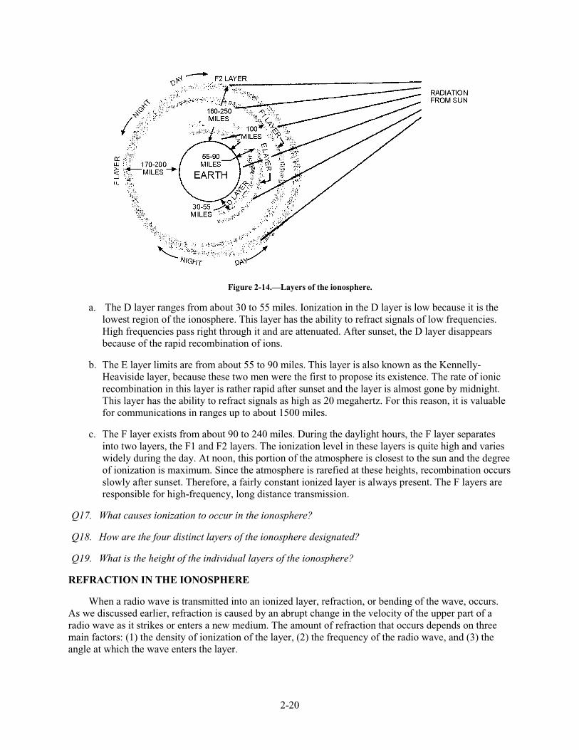
2-20
Figure 2-14.—Layers of the ionosphere.
a. The D layer ranges from about 30 to 55 miles. Ionization in the D layer is low because it is the lowest region of the ionosphere. This layer has the ability to refract signals of low frequencies. High frequencies pass right through it and are attenuated. After sunset, the D layer disappears because of the rapid recombination of ions.
b. The E layer limits are from about 55 to 90 miles. This layer is also known as the Kennelly-Heaviside layer, because these two men were the first to propose its existence. The rate of ionic recombination in this layer is rather rapid after sunset and the layer is almost gone by midnight. This layer has the ability to refract signals as high as 20 megahertz. For this reason, it is valuable for communications in ranges up to about 1500 miles.
c. The F layer exists from about 90 to 240 miles. During the daylight hours, the F layer separates into two layers, the F1 and F2 layers. The ionization level in these layers is quite high and varies widely during the day. At noon, this portion of the atmosphere is closest to the sun and the degree of ionization is maximum. Since the atmosphere is rarefied at these heights, recombination occurs slowly after sunset. Therefore, a fairly constant ionized layer is always present. The F layers are responsible for high-frequency, long distance transmission.
Q17. What causes ionization to occur in the ionosphere?
Q18. How are the four distinct layers of the ionosphere designated?
Q19. What is the height of the individual layers of the ionosphere?
REFRACTION IN THE IONOSPHERE
When a radio wave is transmitted into an ionized layer, refraction, or bending of the wave, occurs. As we discussed earlier, refraction is caused by an abrupt change in the velocity of the upper part of a radio wave as it strikes or enters a new medium. The amount of refraction that occurs depends on three main factors: (1) the density of ionization of the layer, (2) the frequency of the radio wave, and (3) the angle at which the wave enters the layer.
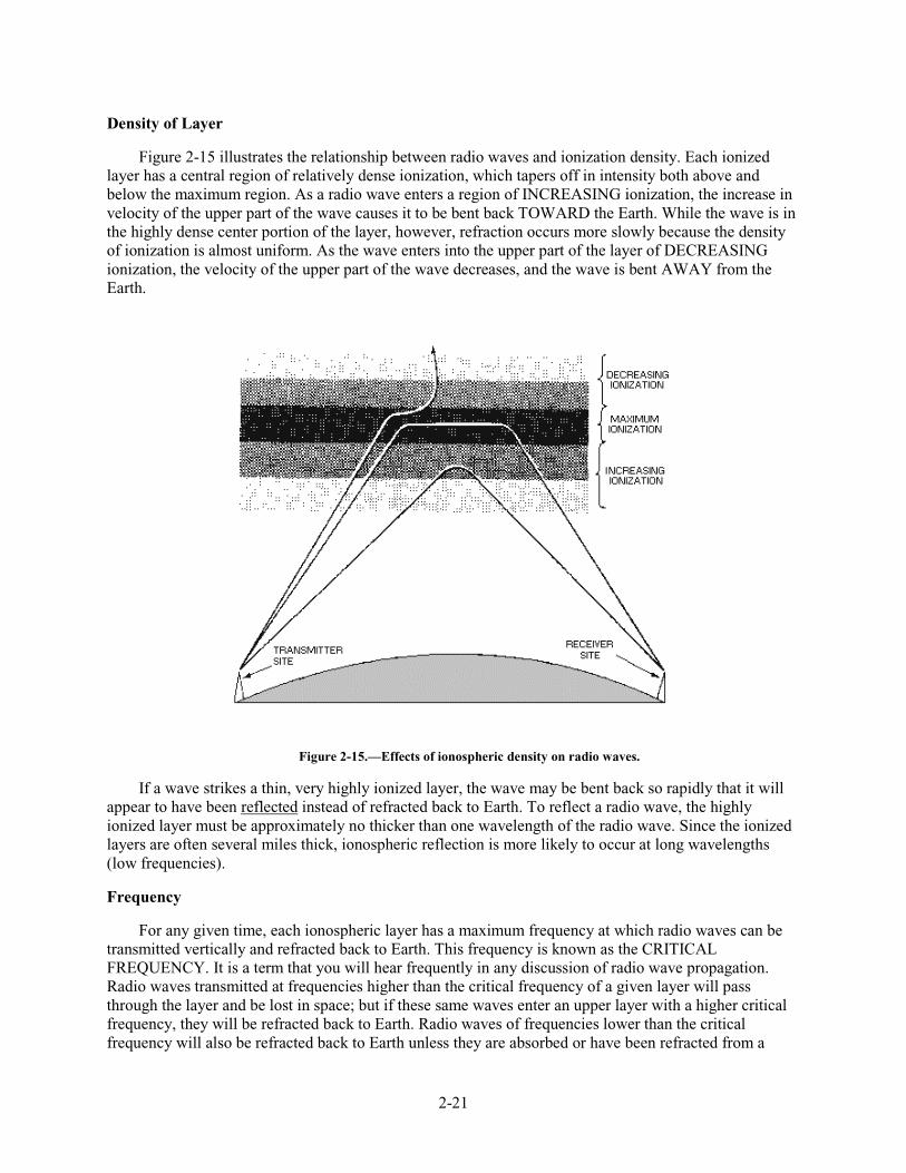
2-21
Density of Layer
Figure 2-15 illustrates the relationship between radio waves and ionization density. Each ionized layer has a central region of relatively dense ionization, which tapers off in intensity both above and below the maximum region. As a radio wave enters a region of INCREASING ionization, the increase in velocity of the upper part of the wave causes it to be bent back TOWARD the Earth. While the wave is in the highly dense center portion of the layer, however, refraction occurs more slowly because the density of ionization is almost uniform. As the wave enters into the upper part of the layer of DECREASING ionization, the velocity of the upper part of the wave decreases, and the wave is bent AWAY from the Earth.
Figure 2-15.—Effects of ionospheric density on radio waves.
If a wave strikes a thin, very highly ionized layer, the wave may be bent back so rapidly that it will appear to have been reflected instead of refracted back to Earth. To reflect a radio wave, the highly ionized layer must be approximately no thicker than one wavelength of the radio wave. Since the ionized layers are often several miles thick, ionospheric reflection is more likely to occur at long wavelengths (low frequencies).
Frequency
For any given time, each ionospheric layer has a maximum frequency at which radio waves can be transmitted vertically and refracted back to Earth. This frequency is known as the CRITICAL FREQUENCY. It is a term that you will hear frequently in any discussion of radio wave propagation. Radio waves transmitted at frequencies higher than the critical frequency of a given layer will pass through the layer and be lost in space; but if these same waves enter an upper layer with a higher critical frequency, they will be refracted back to Earth. Radio waves of frequencies lower than the critical frequency will also be refracted back to Earth unless they are absorbed or have been refracted from a
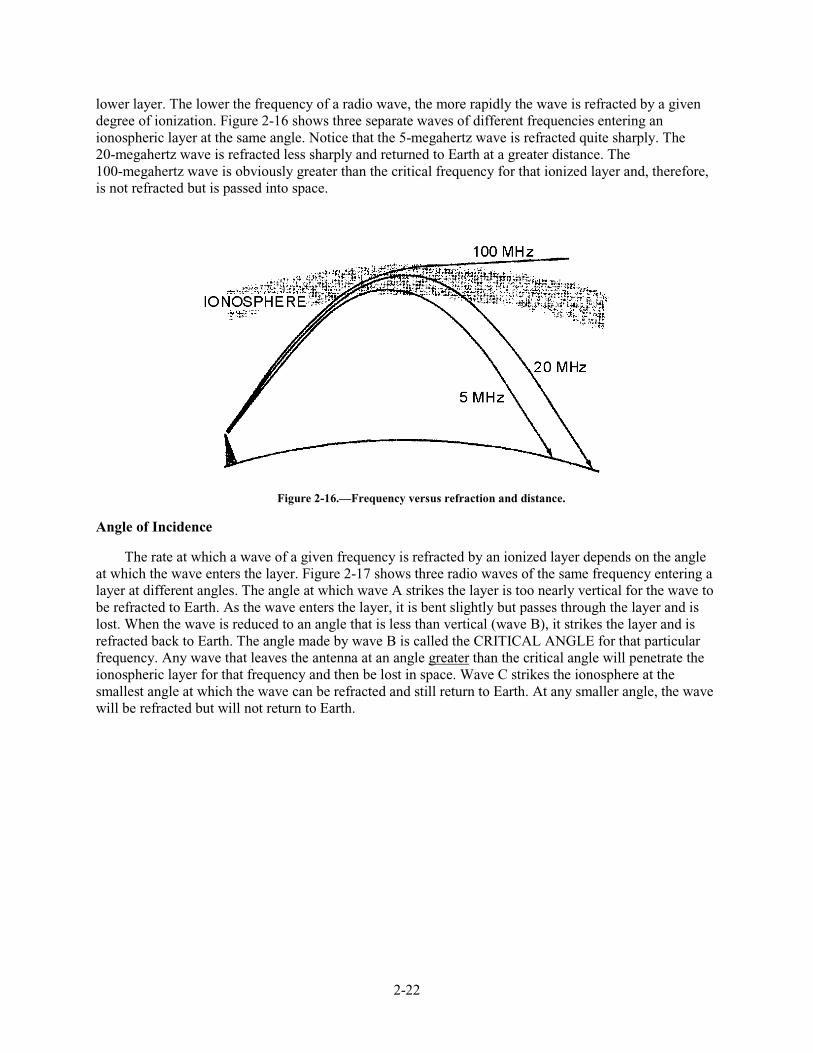
2-22
lower layer. The lower the frequency of a radio wave, the more rapidly the wave is refracted by a given degree of ionization. Figure 2-16 shows three separate waves of different frequencies entering an ionospheric layer at the same angle. Notice that the 5-megahertz wave is refracted quite sharply. The 20-megahertz wave is refracted less sharply and returned to Earth at a greater distance. The 100-megahertz wave is obviously greater than the critical frequency for that ionized layer and, therefore, is not refracted but is passed into space.
Figure 2-16.—Frequency versus refraction and distance.
Angle of Incidence
The rate at which a wave of a given frequency is refracted by an ionized layer depends on the angle at which the wave enters the layer. Figure 2-17 shows three radio waves of the same frequency entering a layer at different angles. The angle at which wave A strikes the layer is too nearly vertical for the wave to be refracted to Earth. As the wave enters the layer, it is bent slightly but passes through the layer and is lost. When the wave is reduced to an angle that is less than vertical (wave B), it strikes the layer and is refracted back to Earth. The angle made by wave B is called the CRITICAL ANGLE for that particular frequency. Any wave that leaves the antenna at an angle greater than the critical angle will penetrate the ionospheric layer for that frequency and then be lost in space. Wave C strikes the ionosphere at the smallest angle at which the wave can be refracted and still return to Earth. At any smaller angle, the wave will be refracted but will not return to Earth.
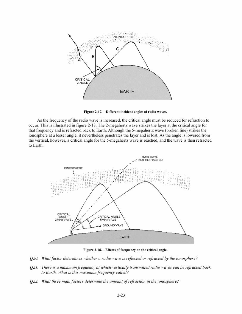
2-23
Figure 2-17.—Different incident angles of radio waves.
As the frequency of the radio wave is increased, the critical angle must be reduced for refraction to occur. This is illustrated in figure 2-18. The 2-megahertz wave strikes the layer at the critical angle for that frequency and is refracted back to Earth. Although the 5-megahertz wave (broken line) strikes the ionosphere at a lesser angle, it nevertheless penetrates the layer and is lost. As the angle is lowered from the vertical, however, a critical angle for the 5-megahertz wave is reached, and the wave is then refracted to Earth.
Figure 2-18.—Effects of frequency on the critical angle.
Q20. What factor determines whether a radio wave is reflected or refracted by the ionosphere?
Q21. There is a maximum frequency at which vertically transmitted radio waves can be refracted back to Earth. What is this maximum frequency called?
Q22. What three main factors determine the amount of refraction in the ionosphere?
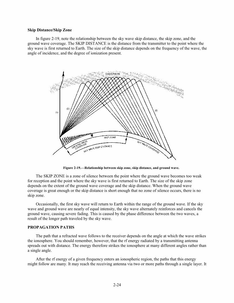
2-24
Skip Distance/Skip Zone
In figure 2-19, note the relationship between the sky wave skip distance, the skip zone, and the ground wave coverage. The SKIP DISTANCE is the distance from the transmitter to the point where the sky wave is first returned to Earth. The size of the skip distance depends on the frequency of the wave, the angle of incidence, and the degree of ionization present.
Figure 2-19.—Relationship between skip zone, skip distance, and ground wave.
The SKIP ZONE is a zone of silence between the point where the ground wave becomes too weak for reception and the point where the sky wave is first returned to Earth. The size of the skip zone depends on the extent of the ground wave coverage and the skip distance. When the ground wave coverage is great enough or the skip distance is short enough that no zone of silence occurs, there is no skip zone.
Occasionally, the first sky wave will return to Earth within the range of the ground wave. If the sky wave and ground wave are nearly of equal intensity, the sky wave alternately reinforces and cancels the ground wave, causing severe fading. This is caused by the phase difference between the two waves, a result of the longer path traveled by the sky wave.
PROPAGATION PATHS
The path that a refracted wave follows to the receiver depends on the angle at which the wave strikes the ionosphere. You should remember, however, that the rf energy radiated by a transmitting antenna spreads out with distance. The energy therefore strikes the ionosphere at many different angles rather than a single angle.
After the rf energy of a given frequency enters an ionospheric region, the paths that this energy might follow are many. It may reach the receiving antenna via two or more paths through a single layer. It
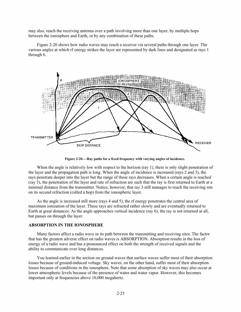
2-25
may also, reach the receiving antenna over a path involving more than one layer, by multiple hops between the ionosphere and Earth, or by any combination of these paths.
Figure 2-20 shows how radio waves may reach a receiver via several paths through one layer. The various angles at which rf energy strikes the layer are represented by dark lines and designated as rays 1 through 6.
Figure 2-20.—Ray paths for a fixed frequency with varying angles of incidence.
When the angle is relatively low with respect to the horizon (ray 1), there is only slight penetration of the layer and the propagation path is long. When the angle of incidence is increased (rays 2 and 3), the rays penetrate deeper into the layer but the range of these rays decreases. When a certain angle is reached (ray 3), the penetration of the layer and rate of refraction are such that the ray is first returned to Earth at a minimal distance from the transmitter. Notice, however, that ray 3 still manages to reach the receiving site on its second refraction (called a hop) from the ionospheric layer.
As the angle is increased still more (rays 4 and 5), the rf energy penetrates the central area of maximum ionization of the layer. These rays are refracted rather slowly and are eventually returned to Earth at great distances. As the angle approaches vertical incidence (ray 6), the ray is not returned at all, but passes on through the layer.
ABSORPTION IN THE IONOSPHERE
Many factors affect a radio wave in its path between the transmitting and receiving sites. The factor that has the greatest adverse effect on radio waves is ABSORPTION. Absorption results in the loss of energy of a radio wave and has a pronounced effect on both the strength of received signals and the ability to communicate over long distances.
You learned earlier in the section on ground waves that surface waves suffer most of their absorption losses because of ground-induced voltage. Sky waves, on the other hand, suffer most of their absorption losses because of conditions in the ionosphere. Note that some absorption of sky waves may also occur at lower atmospheric levels because of the presence of water and water vapor. However, this becomes important only at frequencies above 10,000 megahertz.
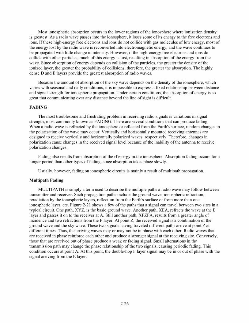
2-26
Most ionospheric absorption occurs in the lower regions of the ionosphere where ionization density is greatest. As a radio wave passes into the ionosphere, it loses some of its energy to the free electrons and ions. If these high-energy free electrons and ions do not collide with gas molecules of low energy, most of the energy lost by the radio wave is reconverted into electromagnetic energy, and the wave continues to be propagated with little change in intensity. However, if the high-energy free electrons and ions do collide with other particles, much of this energy is lost, resulting in absorption of the energy from the wave. Since absorption of energy depends on collision of the particles, the greater the density of the ionized layer, the greater the probability of collisions; therefore, the greater the absorption. The highly dense D and E layers provide the greatest absorption of radio waves.
Because the amount of absorption of the sky wave depends on the density of the ionosphere, which varies with seasonal and daily conditions, it is impossible to express a fixed relationship between distance and signal strength for ionospheric propagation. Under certain conditions, the absorption of energy is so great that communicating over any distance beyond the line of sight is difficult.
FADING
The most troublesome and frustrating problem in receiving radio signals is variations in signal strength, most commonly known as FADING. There are several conditions that can produce fading. When a radio wave is refracted by the ionosphere or reflected from the Earth's surface, random changes in the polarization of the wave may occur. Vertically and horizontally mounted receiving antennas are designed to receive vertically and horizontally polarized waves, respectively. Therefore, changes in polarization cause changes in the received signal level because of the inability of the antenna to receive polarization changes.
Fading also results from absorption of the rf energy in the ionosphere. Absorption fading occurs for a longer period than other types of fading, since absorption takes place slowly.
Usually, however, fading on ionospheric circuits is mainly a result of multipath propagation.
Multipath Fading
MULTIPATH is simply a term used to describe the multiple paths a radio wave may follow between transmitter and receiver. Such propagation paths include the ground wave, ionospheric refraction, reradiation by the ionospheric layers, reflection from the Earth's surface or from more than one ionospheric layer, etc. Figure 2-21 shows a few of the paths that a signal can travel between two sites in a typical circuit. One path, XYZ, is the basic ground wave. Another path, XEA, refracts the wave at the E layer and passes it on to the receiver at A. Still another path, XFZFA, results from a greater angle of incidence and two refractions from the F layer. At point Z, the received signal is a combination of the ground wave and the sky wave. These two signals having traveled different paths arrive at point Z at different times. Thus, the arriving waves may or may not be in phase with each other. Radio waves that are received in phase reinforce each other and produce a stronger signal at the receiving site. Conversely, those that are received out of phase produce a weak or fading signal. Small alternations in the transmission path may change the phase relationship of the two signals, causing periodic fading. This condition occurs at point A. At this point, the double-hop F layer signal may be in or out of phase with the signal arriving from the E layer.
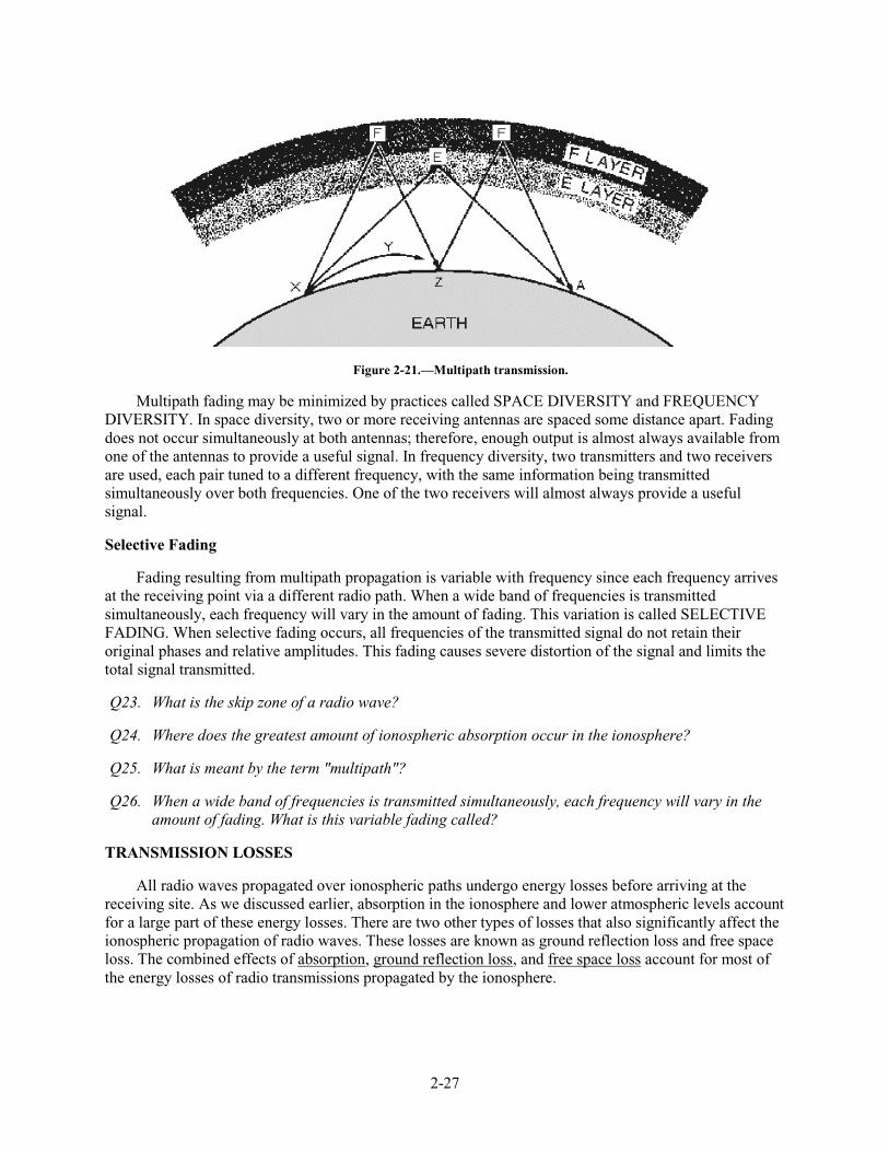
2-27
Figure 2-21.—Multipath transmission.
Multipath fading may be minimized by practices called SPACE DIVERSITY and FREQUENCY DIVERSITY. In space diversity, two or more receiving antennas are spaced some distance apart. Fading does not occur simultaneously at both antennas; therefore, enough output is almost always available from one of the antennas to provide a useful signal. In frequency diversity, two transmitters and two receivers are used, each pair tuned to a different frequency, with the same information being transmitted simultaneously over both frequencies. One of the two receivers will almost always provide a useful signal.
Selective Fading
Fading resulting from multipath propagation is variable with frequency since each frequency arrives at the receiving point via a different radio path. When a wide band of frequencies is transmitted simultaneously, each frequency will vary in the amount of fading. This variation is called SELECTIVE FADING. When selective fading occurs, all frequencies of the transmitted signal do not retain their original phases and relative amplitudes. This fading causes severe distortion of the signal and limits the total signal transmitted.
Q23. What is the skip zone of a radio wave?
Q24. Where does the greatest amount of ionospheric absorption occur in the ionosphere?
Q25. What is meant by the term "multipath"?
Q26. When a wide band of frequencies is transmitted simultaneously, each frequency will vary in the amount of fading. What is this variable fading called?
TRANSMISSION LOSSES
All radio waves propagated over ionospheric paths undergo energy losses before arriving at the receiving site. As we discussed earlier, absorption in the ionosphere and lower atmospheric levels account for a large part of these energy losses. There are two other types of losses that also significantly affect the ionospheric propagation of radio waves. These losses are known as ground reflection loss and free space loss. The combined effects of absorption, ground reflection loss, and free space loss account for most of the energy losses of radio transmissions propagated by the ionosphere.
2-28
Ground Reflection Loss
When propagation is accomplished via multihop refraction, rf energy is lost each time the radio wave is reflected from the Earth's surface. The amount of energy lost depends on the frequency of the wave, the angle of incidence, ground irregularities, and the electrical conductivity of the point of reflection.
Free space Loss
Normally, the major loss of energy is because of the spreading out of the wavefront as it travels away from the transmitter. As the distance increases, the area of the wavefront spreads out, much like the beam of a flashlight. This means the amount of energy contained within any unit of area on the wavefront will decrease as distance increases. By the time the energy arrives at the receiving antenna, the wavefront is so spread out that the receiving antenna extends into only a very small fraction of the wavefront. This is illustrated in figure 2-22.
Figure 2-22.—Free space loss principle.
ELECTROMAGNETIC INTERFERENCE (EMI)
The transmission losses just discussed are not the only factors that interfere with communications. An additional factor that can interfere with radio communications is the presence of ELECTROMAGNETIC INTERFERENCE (EMI). This interference can result in annoying or impossible operating conditions. Sources of emi are both man-made and natural.
Man-Made Interference
Man-made interference may come from several sources. Some of these sources, such as oscillators, communications transmitters, and radio transmitters, may be specifically designed to generate radio frequency energy. Some electrical devices also generate radio frequency energy, although they are not specifically designed for this purpose. Examples are ignition systems, generators, motors, switches, relays, and voltage regulators. The intensity of man-made interference may vary throughout the day and drop off to a low level at night when many of these sources are not being used. Man-made interference may be a critical limiting factor at radio receiving sites located near industrial areas.
2-29
Natural Interference
Natural interference refers to the static that you often hear when listening to a radio. This interference is generated by natural phenomena, such as thunderstorms, snowstorms, cosmic sources, and the sun. The energy released by these sources is transmitted to the receiving site in roughly the same manner as radio waves. As a result, when ionospheric conditions are favorable for the long distance propagation of radio waves, they are likewise favorable for the propagation of natural interference. Natural interference is very erratic, particularly in the hf band, but generally will decrease as the operating frequency is increased and wider bandwidths are used. There is little natural interference above 30 megahertz.
Control of EMI
Electromagnetic interference can be reduced or eliminated by using various suppression techniques. The amount of emi that is produced by a radio transmitter can be controlled by cutting transmitting antennas to the correct frequency, limiting bandwidth, and using electronic filtering networks and metallic shielding.
Radiated emi during transmission can be controlled by the physical separation of the transmitting and receiving antennas, the use of directional antennas, and limiting antenna bandwidth.
Q27. What are the two main sources of emi with which radio waves must compete?
Q28. Thunderstorms, snowstorms, cosmic sources, the sun, etc., are a few examples of emi sources. What type of emi comes from these sources?
Q29. Motors, switches, voltage regulators, generators, etc., are a few examples of emi sources. What type of emi comes from these sources?
Q30. What are three ways of controlling the amount of transmitter-generated emi?
Q31. What are three ways of controlling radiated emi during transmission?
VARIATIONS IN THE IONOSPHERE
Because the existence of the ionosphere is directly related to radiations emitted from the sun, the movement of the Earth about the sun or changes in the sun's activity will result in variations in the ionosphere. These variations are of two general types: (1) those which are more or less regular and occur in cycles and, therefore, can be predicted in advance with reasonable accuracy, and (2) those which are irregular as a result of abnormal behavior of the sun and, therefore, cannot be predicted in advance. Both regular and irregular variations have important effects on radio wave propagation.
Regular Variations
The regular variations that affect the extent of ionization in the ionosphere can be divided into four main classes: daily, seasonal, 11-year, and 27-day variations.
DAILY.—Daily variations in the ionosphere are a result of the 24-hour rotation of the Earth about its axis. Daily variations of the different layers (fig. 2-14) are summarized as follows:
• The D layer reflects vlf waves; is important for long range vlf communications; refracts lf and mf waves for short range communications; absorbs hf waves; has little effect on vhf and above; and disappears at night.
2-30
• In the E layer, ionization depends on the angle of the sun. The E layer refracts hf waves during the day up to 20 megahertz to distances of about 1200 miles. Ionization is greatly reduced at night.
• Structure and density of the F region depend on the time of day and the angle of the sun. This region consists of one layer during the night and splits into two layers during daylight hours.
• Ionization density of the F1 layer depends on the angle of the sun. Its main effect is to absorb hf waves passing through to the F2 layer.
• The F2 layer is the most important layer for long distance hf communications. It is a very variable layer and its height and density change with time of day, season, and sunspot activity.
SEASONAL.—Seasonal variations are the result of the Earth revolving around the sun; the relative position of the sun moves from one hemisphere to the other with changes in seasons. Seasonal variations of the D, E, and F1 layers correspond to the highest angle of the sun; thus the ionization density of these layers is greatest during the summer. The F2 layer, however, does not follow this pattern; its ionization is greatest in winter and least in summer, the reverse of what might be expected. As a result, operating frequencies for F2 layer propagation are higher in the winter than in the summer.
ELEVEN-YEAR SUN SPOT CYCLE.—One of the most notable phenomena on the surface of the sun is the appearance and disappearance of dark, irregularly shaped areas known as SUNSPOTS. The exact nature of sunspots is not known, but scientists believe they are caused by violent eruptions on the sun and are characterized by unusually strong magnetic fields. These sunspots are responsible for variations in the ionization level of the ionosphere. Sunspots can, of course, occur unexpectedly, and the life span of individual sunspots is variable; however, a regular cycle of sunspot activity has also been observed. This cycle has both a minimum and maximum level of sunspot activity that occur approximately every 11 years.
During periods of maximum sunspot activity, the ionization density of all layers increases. Because of this, absorption in the D layer increases and the critical frequencies for the E, F1, and F2 layers are higher. At these times, higher operating frequencies must be used for long distance communications.
27-DAY SUNSPOT CYCLE.—The number of sunspots in existence at any one time is continually subject to change as some disappear and new ones emerge. As the sun rotates on its own axis, these sunspots are visible at 27-day intervals, the approximate period required for the sun to make one complete rotation.
The 27-day sunspot cycle causes variations in the ionization density of the layers on a day-to-day basis. The fluctuations in the F2 layer are greater than for any other layer. For this reason, precise predictions on a day-to-day basis of the critical frequency of the F2 layer are not possible. In calculating frequencies for long-distance communications, allowances for the fluctuations of the F2 layer must be made.
Irregular Variations
Irregular variations in ionospheric conditions also have an important effect on radio wave propagation. Because these variations are irregular and unpredictable, they can drastically affect communications capabilities without any warning.
The more common irregular variations are sporadic E, sudden ionospheric disturbances, and ionospheric storms.
2-31
SPORADIC E.—Irregular cloud-like patches of unusually high ionization, called sporadic E, often form at heights near the normal E layer. Exactly what causes this phenomenon is not known, nor can its occurrence be predicted. It is known to vary significantly with latitude, and in the northern latitudes, it appears to be closely related to the aurora borealis or northern lights.
At times the sporadic E is so thin that radio waves penetrate it easily and are returned to earth by the upper layers. At other times, it extends up to several hundred miles and is heavily ionized.
These characteristics may be either harmful or helpful to radio wave propagation. For example, sporadic E may blank out the use of higher, more favorable ionospheric layers or cause additional absorption of the radio wave at some frequencies. Also, it can cause additional multipath problems and delay the arrival times of the rays of rf energy.
On the other hand, the critical frequency of the sporadic E is very high and can be greater than double the critical frequency of the normal ionospheric layers. This condition may permit the long distance transmission of signals at unusually high frequencies. It may also permit short distance communications to locations that would normally be in the skip zone.
The sporadic E can form and disappear in a short time during either the day or night. However, it usually does not occur at the same time at all transmitting or receiving stations.
SUDDEN IONOSPHERIC DISTURBANCES.—The most startling of the ionospheric irregularities is known as a SUDDEN IONOSPHERIC DISTURBANCE (sid). These disturbances may occur without warning and may prevail for any length of time, from a few minutes to several hours. When sid occurs, long distance propagation of hf radio waves is almost totally "blanked out." The immediate effect is that radio operators listening on normal frequencies are inclined to believe their receivers have gone dead.
When sid has occurred, examination of the sun has revealed a bright solar eruption. All stations lying wholly, or in part, on the sunward side of the Earth are affected. The solar eruption produces an unusually intense burst of ultraviolet light, which is not absorbed by the F2, F1, and E layers, but instead causes a sudden abnormal increase in the ionization density of the D layer. As a result, frequencies above 1 or 2 megahertz are unable to penetrate the D layer and are usually completely absorbed by the layer.
IONOSPHERIC STORMS.—Ionospheric storms are disturbances in the Earth's magnetic field. They are associated, in a manner not fully understood, with both solar eruptions and the 27-day intervals, thus corresponding to the rotation of the sun.
Scientists believe that ionospheric storms result from particle radiation from the sun. Particles radiated from a solar eruption have a slower velocity than ultraviolet light waves produced by the eruption. This would account for the 18-hour or so time difference between a sid and an ionospheric storm. An ionospheric storm that is associated with sunspot activity may begin anytime from 2 days before an active sunspot crosses the central meridian of the sun until four days after it passes the central meridian. At times, however, active sunspots have crossed the central region of the sun without any ionospheric storms occurring. Conversely, ionospheric storms have occurred when there were no visible spots on the sun and no preceding sid. As you can see, some correlation between ionospheric storms, sid, and sunspot activity is possible, but there are no hard and fast rules. Ionospheric storms can occur suddenly without warning.
The most prominent effects of ionospheric storms are a turbulent ionosphere and very erratic sky wave propagation. Critical frequencies are lower than normal, particularly for the F2 layer. Ionospheric storms affect the higher F2 layer first, reducing its ion density. Lower layers are not appreciably affected by the storms unless the disturbance is great. The practical effect of ionospheric storms is that the range of

2-32
frequencies that can be used for communications on a given circuit is much smaller than normal, and communications are possible only at the lower working frequencies.
Q32. What are the two general types of variations in the ionosphere?
Q33. What is the main difference between these two types of variations?
Q34. What are the four main classes of regular variation which affect the extent of ionization in the ionosphere?
Q35. What are the three more common types of irregular variations in the ionosphere?
FREQUENCY SELECTION CONSIDERATIONS
Up to this point, we have covered various factors that control the propagation of radio waves through the ionosphere, such as the structure of the ionosphere, the incidence angle of radio waves, operating frequencies, etc. There is a very good reason for studying radio wave propagation. You must have a thorough knowledge of radio wave propagation to exercise good judgment when you select transmitting and receiving antennas and operating frequencies. Selection of a suitable operating frequency (within the bounds of frequency allocations and availability) is of prime importance in maintaining reliable communications.
For successful communications between any two specified locations at any given time of the day, there is a maximum frequency, a lowest frequency, and an optimum frequency that can be used.
Maximum Usable Frequency
As we discussed earlier, the higher the frequency of a radio wave, the lower the rate of refraction by an ionized layer. Therefore, for a given angle of incidence and time of day, there is a maximum frequency that can be used for communications between two given locations. This frequency is known as the MAXIMUM USABLE FREQUENCY (muf).
Waves at frequencies above the muf are normally refracted so slowly that they return to Earth beyond the desired location, or pass on through the ionosphere and are lost. You should understand, however, that use of an established muf certainly does not guarantee successful communications between a transmitting site and a receiving site. Variations in the ionosphere may occur at any time and consequently raise or lower the predetermined muf. This is particularly true for radio waves being refracted by the highly variable F2 layer.
The muf is highest around noon when ultraviolet light waves from the sun are the most intense. It then drops rather sharply as recombination begins to take place.
Lowest Usable Frequency
As there is a maximum operating frequency that can be used for communications between two points, there is also a minimum operating frequency. This is known as the LOWEST USABLE FREQUENCY (luf).
As the frequency of a radio wave is lowered, the rate of refraction increases. So a wave whose frequency is below the established luf is refracted back to Earth at a shorter distance than desired, as shown in figure 2-23.
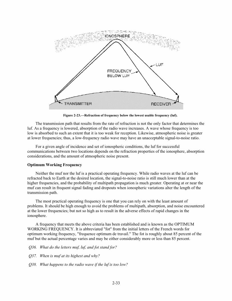
2-33
Figure 2-23.—Refraction of frequency below the lowest usable frequency (luf).
The transmission path that results from the rate of refraction is not the only factor that determines the luf. As a frequency is lowered, absorption of the radio wave increases. A wave whose frequency is too low is absorbed to such an extent that it is too weak for reception. Likewise, atmospheric noise is greater at lower frequencies; thus, a low-frequency radio wave may have an unacceptable signal-to-noise ratio.
For a given angle of incidence and set of ionospheric conditions, the luf for successful communications between two locations depends on the refraction properties of the ionosphere, absorption considerations, and the amount of atmospheric noise present.
Optimum Working Frequency
Neither the muf nor the luf is a practical operating frequency. While radio waves at the luf can be refracted back to Earth at the desired location, the signal-to-noise ratio is still much lower than at the higher frequencies, and the probability of multipath propagation is much greater. Operating at or near the muf can result in frequent signal fading and dropouts when ionospheric variations alter the length of the transmission path.
The most practical operating frequency is one that you can rely on with the least amount of problems. It should be high enough to avoid the problems of multipath, absorption, and noise encountered at the lower frequencies; but not so high as to result in the adverse effects of rapid changes in the ionosphere.
A frequency that meets the above criteria has been established and is known as the OPTIMUM WORKING FREQUENCY. It is abbreviated "fot" from the initial letters of the French words for optimum working frequency, "frequence optimum de travail." The fot is roughly about 85 percent of the muf but the actual percentage varies and may be either considerably more or less than 85 percent.
Q36. What do the letters muf, luf, and fot stand for?
Q37. When is muf at its highest and why?
Q38. What happens to the radio wave if the luf is too low?
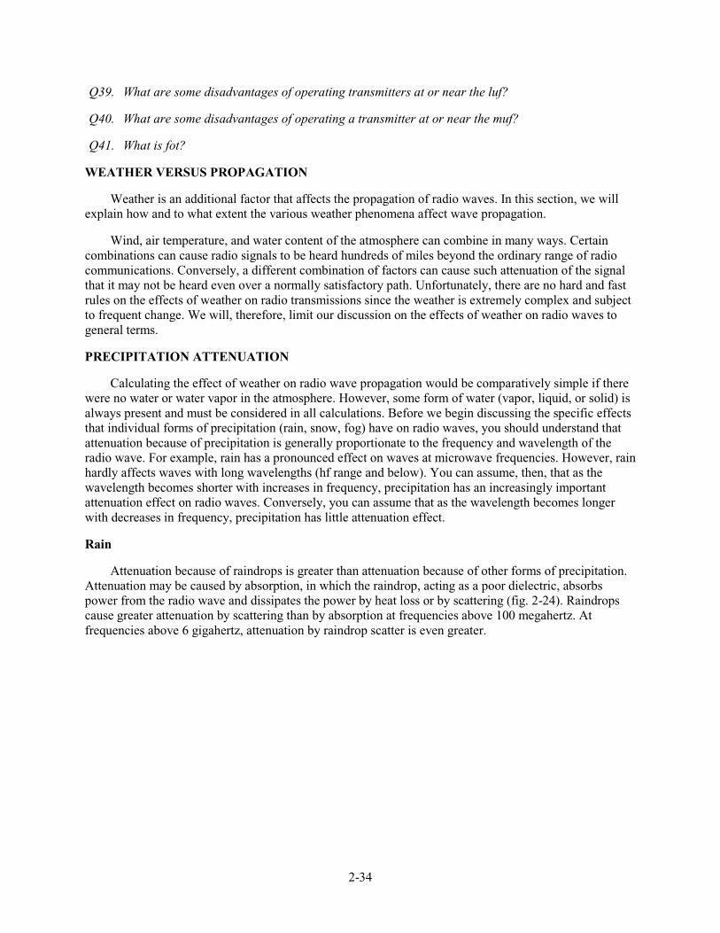
2-34
Q39. What are some disadvantages of operating transmitters at or near the luf?
Q40. What are some disadvantages of operating a transmitter at or near the muf?
Q41. What is fot?
WEATHER VERSUS PROPAGATION
Weather is an additional factor that affects the propagation of radio waves. In this section, we will explain how and to what extent the various weather phenomena affect wave propagation.
Wind, air temperature, and water content of the atmosphere can combine in many ways. Certain combinations can cause radio signals to be heard hundreds of miles beyond the ordinary range of radio communications. Conversely, a different combination of factors can cause such attenuation of the signal that it may not be heard even over a normally satisfactory path. Unfortunately, there are no hard and fast rules on the effects of weather on radio transmissions since the weather is extremely complex and subject to frequent change. We will, therefore, limit our discussion on the effects of weather on radio waves to general terms.
PRECIPITATION ATTENUATION
Calculating the effect of weather on radio wave propagation would be comparatively simple if there were no water or water vapor in the atmosphere. However, some form of water (vapor, liquid, or solid) is always present and must be considered in all calculations. Before we begin discussing the specific effects that individual forms of precipitation (rain, snow, fog) have on radio waves, you should understand that attenuation because of precipitation is generally proportionate to the frequency and wavelength of the radio wave. For example, rain has a pronounced effect on waves at microwave frequencies. However, rain hardly affects waves with long wavelengths (hf range and below). You can assume, then, that as the wavelength becomes shorter with increases in frequency, precipitation has an increasingly important attenuation effect on radio waves. Conversely, you can assume that as the wavelength becomes longer with decreases in frequency, precipitation has little attenuation effect.
Rain
Attenuation because of raindrops is greater than attenuation because of other forms of precipitation. Attenuation may be caused by absorption, in which the raindrop, acting as a poor dielectric, absorbs power from the radio wave and dissipates the power by heat loss or by scattering (fig. 2-24). Raindrops cause greater attenuation by scattering than by absorption at frequencies above 100 megahertz. At frequencies above 6 gigahertz, attenuation by raindrop scatter is even greater.
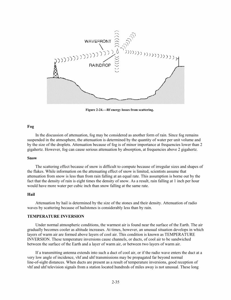
2-35
Figure 2-24.—Rf energy losses from scattering.
Fog
In the discussion of attenuation, fog may be considered as another form of rain. Since fog remains suspended in the atmosphere, the attenuation is determined by the quantity of water per unit volume and by the size of the droplets. Attenuation because of fog is of minor importance at frequencies lower than 2 gigahertz. However, fog can cause serious attenuation by absorption, at frequencies above 2 gigahertz.
Snow
The scattering effect because of snow is difficult to compute because of irregular sizes and shapes of the flakes. While information on the attenuating effect of snow is limited, scientists assume that attenuation from snow is less than from rain falling at an equal rate. This assumption is borne out by the fact that the density of rain is eight times the density of snow. As a result, rain falling at 1 inch per hour would have more water per cubic inch than snow falling at the same rate.
Hail
Attenuation by hail is determined by the size of the stones and their density. Attenuation of radio waves by scattering because of hailstones is considerably less than by rain.
TEMPERATURE INVERSION
Under normal atmospheric conditions, the warmest air is found near the surface of the Earth. The air gradually becomes cooler as altitude increases. At times, however, an unusual situation develops in which layers of warm air are formed above layers of cool air. This condition is known as TEMPERATURE INVERSION. These temperature inversions cause channels, or ducts, of cool air to be sandwiched between the surface of the Earth and a layer of warm air, or between two layers of warm air.
If a transmitting antenna extends into such a duct of cool air, or if the radio wave enters the duct at a very low angle of incidence, vhf and uhf transmissions may be propagated far beyond normal line-of-sight distances. When ducts are present as a result of temperature inversions, good reception of vhf and uhf television signals from a station located hundreds of miles away is not unusual. These long
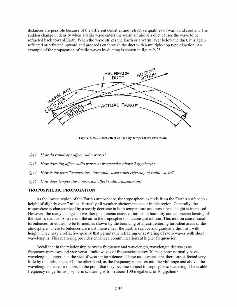
2-36
distances are possible because of the different densities and refractive qualities of warm and cool air. The sudden change in density when a radio wave enters the warm air above a duct causes the wave to be refracted back toward Earth. When the wave strikes the Earth or a warm layer below the duct, it is again reflected or refracted upward and proceeds on through the duct with a multiple-hop type of action. An example of the propagation of radio waves by ducting is shown in figure 2-25.
Figure 2-25.—Duct effect caused by temperature inversion.
Q42. How do raindrops affect radio waves?
Q43. How does fog affect radio waves at frequencies above 2 gigahertz?
Q44. How is the term "temperature inversion" used when referring to radio waves?
Q45. How does temperature inversion affect radio transmission?
TROPOSPHERIC PROPAGATION
As the lowest region of the Earth's atmosphere, the troposphere extends from the Earth's surface to a height of slightly over 7 miles. Virtually all weather phenomena occur in this region. Generally, the troposphere is characterized by a steady decrease in both temperature and pressure as height is increased. However, the many changes in weather phenomena cause variations in humidity and an uneven heating of the Earth's surface. As a result, the air in the troposphere is in constant motion. This motion causes small turbulences, or eddies, to be formed, as shown by the bouncing of aircraft entering turbulent areas of the atmosphere. These turbulences are most intense near the Earth's surface and gradually diminish with height. They have a refractive quality that permits the refracting or scattering of radio waves with short wavelengths. This scattering provides enhanced communications at higher frequencies.
Recall that in the relationship between frequency and wavelength, wavelength decreases as frequency increases and vice versa. Radio waves of frequencies below 30 megahertz normally have wavelengths longer than the size of weather turbulences. These radio waves are, therefore, affected very little by the turbulences. On the other hand, as the frequency increases into the vhf range and above, the wavelengths decrease in size, to the point that they become subject to tropospheric scattering. The usable frequency range for tropospheric scattering is from about 100 megahertz to 10 gigahertz.
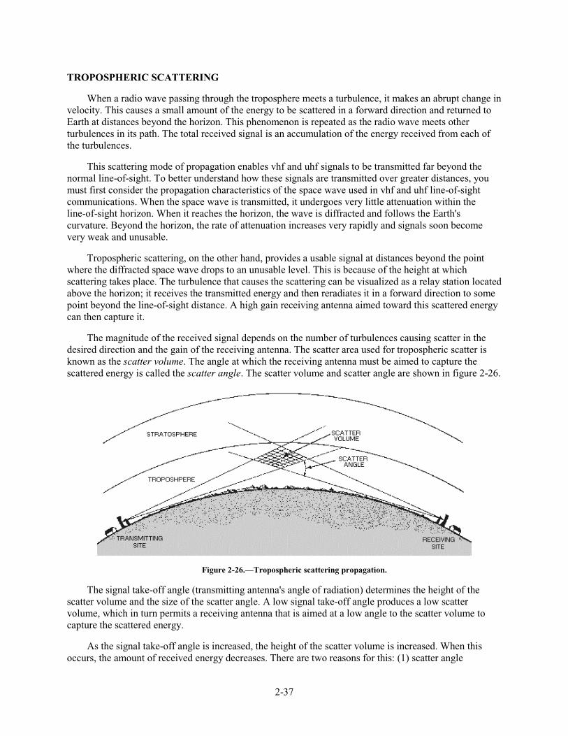
2-37
TROPOSPHERIC SCATTERING
When a radio wave passing through the troposphere meets a turbulence, it makes an abrupt change in velocity. This causes a small amount of the energy to be scattered in a forward direction and returned to Earth at distances beyond the horizon. This phenomenon is repeated as the radio wave meets other turbulences in its path. The total received signal is an accumulation of the energy received from each of the turbulences.
This scattering mode of propagation enables vhf and uhf signals to be transmitted far beyond the normal line-of-sight. To better understand how these signals are transmitted over greater distances, you must first consider the propagation characteristics of the space wave used in vhf and uhf line-of-sight communications. When the space wave is transmitted, it undergoes very little attenuation within the line-of-sight horizon. When it reaches the horizon, the wave is diffracted and follows the Earth's curvature. Beyond the horizon, the rate of attenuation increases very rapidly and signals soon become very weak and unusable.
Tropospheric scattering, on the other hand, provides a usable signal at distances beyond the point where the diffracted space wave drops to an unusable level. This is because of the height at which scattering takes place. The turbulence that causes the scattering can be visualized as a relay station located above the horizon; it receives the transmitted energy and then reradiates it in a forward direction to some point beyond the line-of-sight distance. A high gain receiving antenna aimed toward this scattered energy can then capture it.
The magnitude of the received signal depends on the number of turbulences causing scatter in the desired direction and the gain of the receiving antenna. The scatter area used for tropospheric scatter is known as the scatter volume. The angle at which the receiving antenna must be aimed to capture the scattered energy is called the scatter angle. The scatter volume and scatter angle are shown in figure 2-26.
Figure 2-26.—Tropospheric scattering propagation.
The signal take-off angle (transmitting antenna's angle of radiation) determines the height of the scatter volume and the size of the scatter angle. A low signal take-off angle produces a low scatter volume, which in turn permits a receiving antenna that is aimed at a low angle to the scatter volume to capture the scattered energy.
As the signal take-off angle is increased, the height of the scatter volume is increased. When this occurs, the amount of received energy decreases. There are two reasons for this: (1) scatter angle
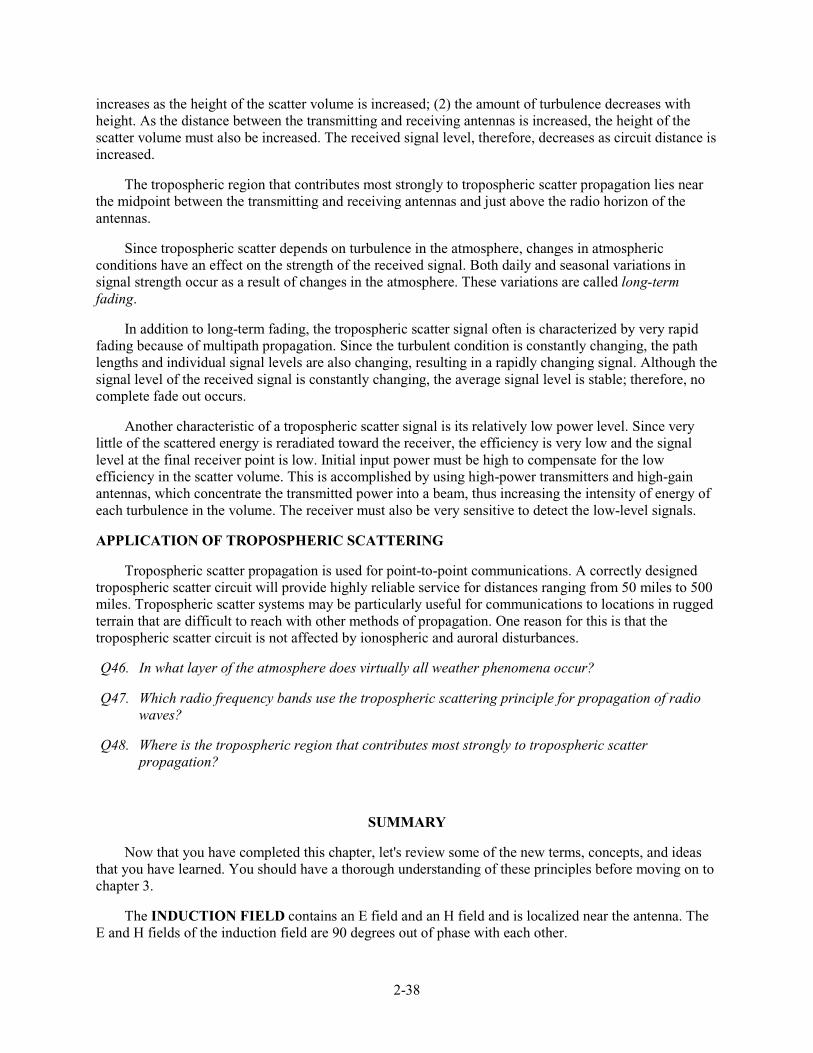
2-38
increases as the height of the scatter volume is increased; (2) the amount of turbulence decreases with height. As the distance between the transmitting and receiving antennas is increased, the height of the scatter volume must also be increased. The received signal level, therefore, decreases as circuit distance is increased.
The tropospheric region that contributes most strongly to tropospheric scatter propagation lies near the midpoint between the transmitting and receiving antennas and just above the radio horizon of the antennas.
Since tropospheric scatter depends on turbulence in the atmosphere, changes in atmospheric conditions have an effect on the strength of the received signal. Both daily and seasonal variations in signal strength occur as a result of changes in the atmosphere. These variations are called long-term fading.
In addition to long-term fading, the tropospheric scatter signal often is characterized by very rapid fading because of multipath propagation. Since the turbulent condition is constantly changing, the path lengths and individual signal levels are also changing, resulting in a rapidly changing signal. Although the signal level of the received signal is constantly changing, the average signal level is stable; therefore, no complete fade out occurs.
Another characteristic of a tropospheric scatter signal is its relatively low power level. Since very little of the scattered energy is reradiated toward the receiver, the efficiency is very low and the signal level at the final receiver point is low. Initial input power must be high to compensate for the low efficiency in the scatter volume. This is accomplished by using high-power transmitters and high-gain antennas, which concentrate the transmitted power into a beam, thus increasing the intensity of energy of each turbulence in the volume. The receiver must also be very sensitive to detect the low-level signals.
APPLICATION OF TROPOSPHERIC SCATTERING
Tropospheric scatter propagation is used for point-to-point communications. A correctly designed tropospheric scatter circuit will provide highly reliable service for distances ranging from 50 miles to 500 miles. Tropospheric scatter systems may be particularly useful for communications to locations in rugged terrain that are difficult to reach with other methods of propagation. One reason for this is that the tropospheric scatter circuit is not affected by ionospheric and auroral disturbances.
Q46. In what layer of the atmosphere does virtually all weather phenomena occur?
Q47. Which radio frequency bands use the tropospheric scattering principle for propagation of radio waves?
Q48. Where is the tropospheric region that contributes most strongly to tropospheric scatter propagation?
SUMMARY
Now that you have completed this chapter, let's review some of the new terms, concepts, and ideas that you have learned. You should have a thorough understanding of these principles before moving on to chapter 3.
The INDUCTION FIELD contains an E field and an H field and is localized near the antenna. The E and H fields of the induction field are 90 degrees out of phase with each other.
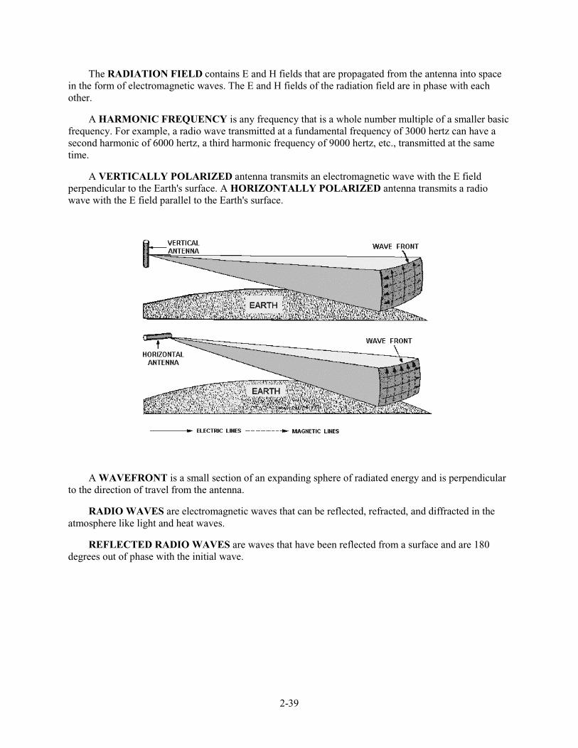
2-39
The RADIATION FIELD contains E and H fields that are propagated from the antenna into space in the form of electromagnetic waves. The E and H fields of the radiation field are in phase with each other.
A HARMONIC FREQUENCY is any frequency that is a whole number multiple of a smaller basic frequency. For example, a radio wave transmitted at a fundamental frequency of 3000 hertz can have a second harmonic of 6000 hertz, a third harmonic frequency of 9000 hertz, etc., transmitted at the same time.
A VERTICALLY POLARIZED antenna transmits an electromagnetic wave with the E field perpendicular to the Earth's surface. A HORIZONTALLY POLARIZED antenna transmits a radio wave with the E field parallel to the Earth's surface.
A WAVEFRONT is a small section of an expanding sphere of radiated energy and is perpendicular to the direction of travel from the antenna.
RADIO WAVES are electromagnetic waves that can be reflected, refracted, and diffracted in the atmosphere like light and heat waves.
REFLECTED RADIO WAVES are waves that have been reflected from a surface and are 180 degrees out of phase with the initial wave.
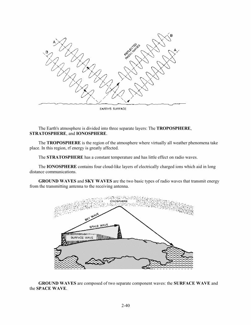
2-40
The Earth's atmosphere is divided into three separate layers: The TROPOSPHERE, STRATOSPHERE, and IONOSPHERE.
The TROPOSPHERE is the region of the atmosphere where virtually all weather phenomena take place. In this region, rf energy is greatly affected.
The STRATOSPHERE has a constant temperature and has little effect on radio waves.
The IONOSPHERE contains four cloud-like layers of electrically charged ions which aid in long distance communications.
GROUND WAVES and SKY WAVES are the two basic types of radio waves that transmit energy from the transmitting antenna to the receiving antenna.
GROUND WAVES are composed of two separate component waves: the SURFACE WAVE and the SPACE WAVE.
2-41
SURFACE WAVES travel along the contour of the Earth by diffraction.
SPACE WAVES can travel through the air directly to the receiving antenna or can be reflected from the surface of the Earth.
SKY WAVES, often called ionospheric waves, are radiated in an upward direction and returned to Earth at some distant location because of refraction.
NATURAL HORIZON is the line-of-sight horizon.
RADIO HORIZON is one-third farther than the natural horizon.
The IONOSPHERE consists of several layers of ions, formed by the process called ionization.
IONIZATION is the process of knocking electrons free from their parent atom, thus upsetting electrical neutrality.
RECOMBINATION is the opposite of ionization; that is, the free ions combine with positive ions, causing the positive ions to return to their original neutral atom state.
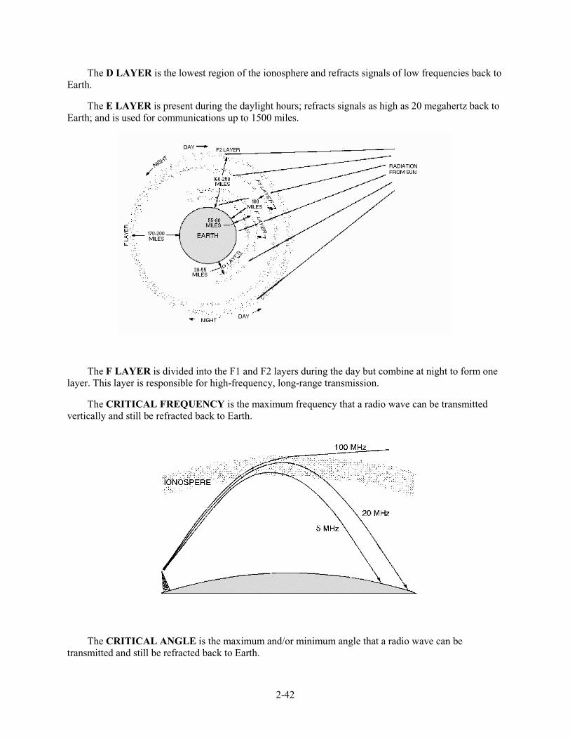
2-42
The D LAYER is the lowest region of the ionosphere and refracts signals of low frequencies back to Earth.
The E LAYER is present during the daylight hours; refracts signals as high as 20 megahertz back to Earth; and is used for communications up to 1500 miles.
The F LAYER is divided into the F1 and F2 layers during the day but combine at night to form one layer. This layer is responsible for high-frequency, long-range transmission.
The CRITICAL FREQUENCY is the maximum frequency that a radio wave can be transmitted vertically and still be refracted back to Earth.
The CRITICAL ANGLE is the maximum and/or minimum angle that a radio wave can be transmitted and still be refracted back to Earth.
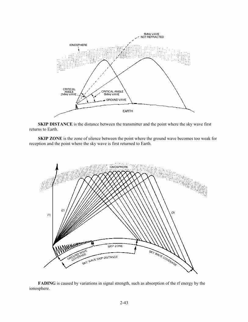
2-43
SKIP DISTANCE is the distance between the transmitter and the point where the sky wave first returns to Earth.
SKIP ZONE is the zone of silence between the point where the ground wave becomes too weak for reception and the point where the sky wave is first returned to Earth.
FADING is caused by variations in signal strength, such as absorption of the rf energy by the ionosphere.

2-44
MULTIPATH FADING occurs when a transmitted signal divides and takes more than one path to a receiver and some of the signals arrive out of phase, resulting in a weak or fading signal.
Some TRANSMISSION LOSSES that affect radio-wave propagation are ionospheric absorption, ground reflection, and free-space losses.
ELECTROMAGNETIC INTERFERENCE (emi), both natural and man-made, interfere with radio communications.
The MAXIMUM USABLE FREQUENCY (muf) is the highest frequency that can be used for communications between two locations at a given angle of incidence and time of day.
The LOWEST USABLE FREQUENCY (luf) is the lowest frequency that can be used for communications between two locations.
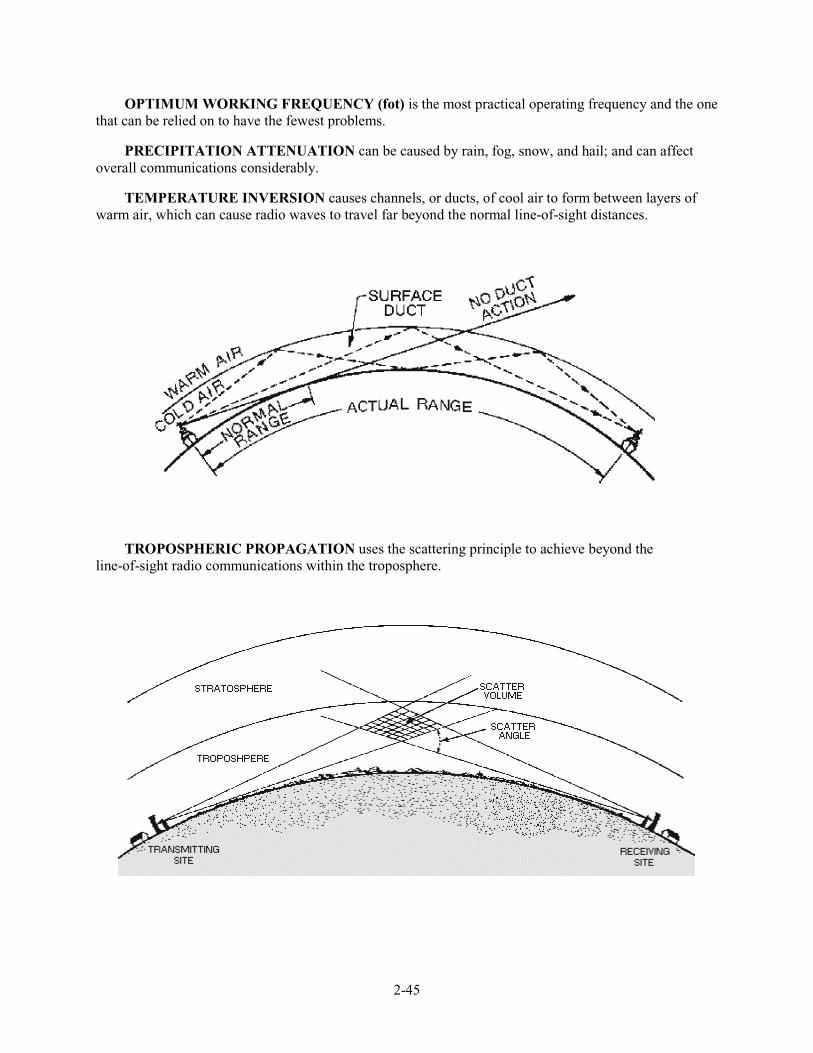
2-45
OPTIMUM WORKING FREQUENCY (fot) is the most practical operating frequency and the one that can be relied on to have the fewest problems.
PRECIPITATION ATTENUATION can be caused by rain, fog, snow, and hail; and can affect overall communications considerably.
TEMPERATURE INVERSION causes channels, or ducts, of cool air to form between layers of warm air, which can cause radio waves to travel far beyond the normal line-of-sight distances.
TROPOSPHERIC PROPAGATION uses the scattering principle to achieve beyond the line-of-sight radio communications within the troposphere.
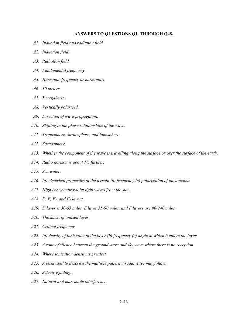
2-46
ANSWERS TO QUESTIONS Q1. THROUGH Q48.
A1. Induction field and radiation field.
A2. Induction field.
A3. Radiation field.
A4. Fundamental frequency.
A5. Harmonic frequency or harmonics.
A6. 30 meters.
A7. 5 megahertz.
A8. Vertically polarized.
A9. Direction of wave propagation.
A10. Shifting in the phase relationships of the wave.
A11. Troposphere, stratosphere, and ionosphere.
A12. Stratosphere.
A13. Whether the component of the wave is travelling along the surface or over the surface of the earth.
A14. Radio horizon is about 1/3 farther.
A15. Sea water.
A16. (a) electrical properties of the terrain (b) frequency (c) polarization of the antenna
A17. High energy ultraviolet light waves from the sun.
A18. D, E, F1, and F2 layers.
A19. D layer is 30-55 miles, E layer 55-90 miles, and F layers are 90-240 miles.
A20. Thickness of ionized layer.
A21. Critical frequency.
A22. (a) density of ionization of the layer (b) frequency (c) angle at which it enters the layer
A23. A zone of silence between the ground wave and sky wave where there is no reception.
A24. Where ionization density is greatest.
A25. A term used to describe the multiple pattern a radio wave may follow.
A26. Selective fading.
A27. Natural and man-made interference.
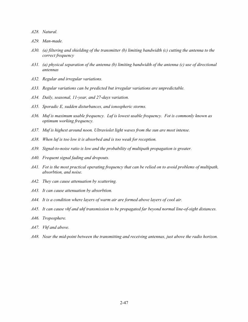
2-47
A28. Natural.
A29. Man-made.
A30. (a) filtering and shielding of the transmitter (b) limiting bandwidth (c) cutting the antenna to the correct frequency
A31. (a) physical separation of the antenna (b) limiting bandwidth of the antenna (c) use of directional antennas
A32. Regular and irregular variations.
A33. Regular variations can be predicted but irregular variations are unpredictable.
A34. Daily, seasonal, 11-year, and 27-days variation.
A35. Sporadic E, sudden disturbances, and ionospheric storms.
A36. Muf is maximum usable frequency. Luf is lowest usable frequency. Fot is commonly known as optimum working frequency.
A37. Muf is highest around noon. Ultraviolet light waves from the sun are most intense.
A38. When luf is too low it is absorbed and is too weak for reception.
A39. Signal-to-noise ratio is low and the probability of multipath propagation is greater.
A40. Frequent signal fading and dropouts.
A41. Fot is the most practical operating frequency that can be relied on to avoid problems of multipath, absorbtion, and noise.
A42. They can cause attenuation by scattering.
A43. It can cause attenuation by absorbtion.
A44. It is a condition where layers of warm air are formed above layers of cool air.
A45. It can cause vhf and uhf transmission to be propagated far beyond normal line-of-sight distances.
A46. Troposphere.
A47. Vhf and above.
A48. Near the mid-point between the transmitting and receiving antennas, just above the radio horizon.


3-1
CHAPTER 3
PRINCIPLES OF TRANSMISSION LINES
LEARNING OBJECTIVES
Upon completion of this chapter, you will be able to:
1. State what a transmission line is and how transmission lines are used.
2. Explain the operating principles of transmission lines.
3. Describe the five types of transmission lines.
4. State the length of a transmission line.
5. Explain the theory of the transmission line.
6. Define the term LUMPED CONSTANTS in relation to a transmission line.
7. Define the term DISTRIBUTED CONSTANTS in relation to a transmission line.
8. Define LEAKAGE CURRENT.
9. Describe how the electromagnetic lines of force around a transmission line are affected by thedistributed constants.
10. Define the term CHARACTERISTIC IMPEDANCE and explain how it affects the transfer ofenergy along a transmission line.
11. State how the energy transfer along a transmission line is affected by characteristic impedance andthe infinite line.
12. Identify the cause of and describe the characteristics of reflections on a transmission line.
13. Define the term STANDING WAVES as applied to a transmission line.
14. Describe how standing waves are produced on a transmission line and identify the types ofterminations.
15. Describe the types of standing-wave ratios.
INTRODUCTION TO TRANSMISSION LINES
A TRANSMISSION LINE is a device designed to guide electrical energy from one point to another.It is used, for example, to transfer the output rf energy of a transmitter to an antenna. This energy will nottravel through normal electrical wire without great losses. Although the antenna can be connected directlyto the transmitter, the antenna is usually located some distance away from the transmitter. On board ship,
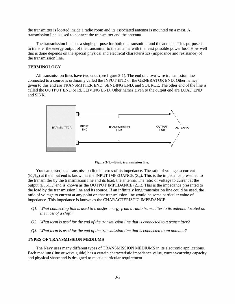
3-2
the transmitter is located inside a radio room and its associated antenna is mounted on a mast. Atransmission line is used to connect the transmitter and the antenna.
The transmission line has a single purpose for both the transmitter and the antenna. This purpose isto transfer the energy output of the transmitter to the antenna with the least possible power loss. How wellthis is done depends on the special physical and electrical characteristics (impedance and resistance) ofthe transmission line.
TERMINOLOGY
All transmission lines have two ends (see figure 3-1). The end of a two-wire transmission lineconnected to a source is ordinarily called the INPUT END or the GENERATOR END. Other namesgiven to this end are TRANSMITTER END, SENDING END, and SOURCE. The other end of the line iscalled the OUTPUT END or RECEIVING END. Other names given to the output end are LOAD ENDand SINK.
Figure 3-1.—Basic transmission line.
You can describe a transmission line in terms of its impedance. The ratio of voltage to current(Ein/Iin) at the input end is known as the INPUT IMPEDANCE (Zin). This is the impedance presented tothe transmitter by the transmission line and its load, the antenna. The ratio of voltage to current at theoutput (Eout/Iout) end is known as the OUTPUT IMPEDANCE (Zout). This is the impedance presented tothe load by the transmission line and its source. If an infinitely long transmission line could be used, theratio of voltage to current at any point on that transmission line would be some particular value ofimpedance. This impedance is known as the CHARACTERISTIC IMPEDANCE.
Q1. What connecting link is used to transfer energy from a radio transmitter to its antenna located onthe mast of a ship?
Q2. What term is used for the end of the transmission line that is connected to a transmitter?
Q3. What term is used for the end of the transmission line that is connected to an antenna?
TYPES OF TRANSMISSION MEDIUMS
The Navy uses many different types of TRANSMISSION MEDIUMS in its electronic applications.Each medium (line or wave guide) has a certain characteristic impedance value, current-carrying capacity,and physical shape and is designed to meet a particular requirement.
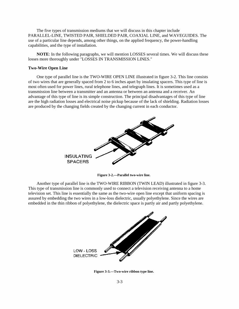
3-3
The five types of transmission mediums that we will discuss in this chapter includePARALLEL-LINE, TWISTED PAIR, SHIELDED PAIR, COAXIAL LINE, and WAVEGUIDES. Theuse of a particular line depends, among other things, on the applied frequency, the power-handlingcapabilities, and the type of installation.
NOTE: In the following paragraphs, we will mention LOSSES several times. We will discuss theselosses more thoroughly under "LOSSES IN TRANSMISSION LINES."
Two-Wire Open Line
One type of parallel line is the TWO-WIRE OPEN LINE illustrated in figure 3-2. This line consistsof two wires that are generally spaced from 2 to 6 inches apart by insulating spacers. This type of line ismost often used for power lines, rural telephone lines, and telegraph lines. It is sometimes used as atransmission line between a transmitter and an antenna or between an antenna and a receiver. Anadvantage of this type of line is its simple construction. The principal disadvantages of this type of lineare the high radiation losses and electrical noise pickup because of the lack of shielding. Radiation lossesare produced by the changing fields created by the changing current in each conductor.
Figure 3-2.—Parallel two-wire line.
Another type of parallel line is the TWO-WIRE RIBBON (TWIN LEAD) illustrated in figure 3-3.This type of transmission line is commonly used to connect a television receiving antenna to a hometelevision set. This line is essentially the same as the two-wire open line except that uniform spacing isassured by embedding the two wires in a low-loss dielectric, usually polyethylene. Since the wires areembedded in the thin ribbon of polyethylene, the dielectric space is partly air and partly polyethylene.
Figure 3-3.—Two-wire ribbon type line.
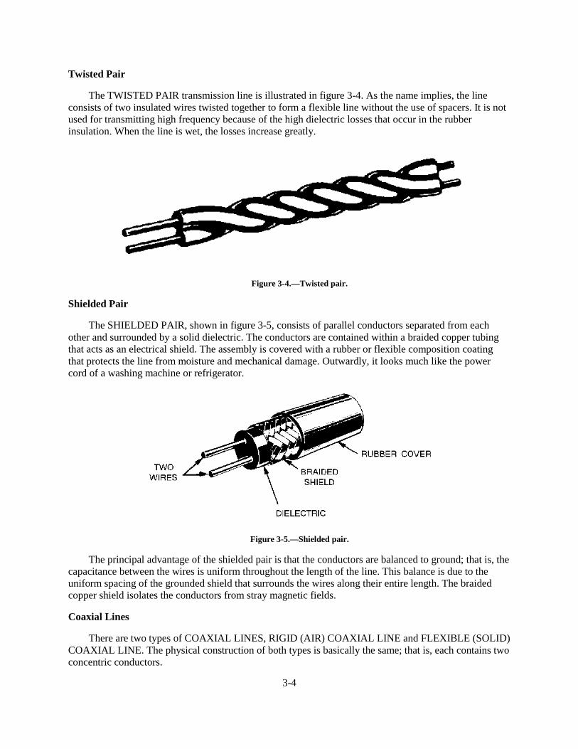
3-4
Twisted Pair
The TWISTED PAIR transmission line is illustrated in figure 3-4. As the name implies, the lineconsists of two insulated wires twisted together to form a flexible line without the use of spacers. It is notused for transmitting high frequency because of the high dielectric losses that occur in the rubberinsulation. When the line is wet, the losses increase greatly.
Figure 3-4.—Twisted pair.
Shielded Pair
The SHIELDED PAIR, shown in figure 3-5, consists of parallel conductors separated from eachother and surrounded by a solid dielectric. The conductors are contained within a braided copper tubingthat acts as an electrical shield. The assembly is covered with a rubber or flexible composition coatingthat protects the line from moisture and mechanical damage. Outwardly, it looks much like the powercord of a washing machine or refrigerator.
Figure 3-5.—Shielded pair.
The principal advantage of the shielded pair is that the conductors are balanced to ground; that is, thecapacitance between the wires is uniform throughout the length of the line. This balance is due to theuniform spacing of the grounded shield that surrounds the wires along their entire length. The braidedcopper shield isolates the conductors from stray magnetic fields.
Coaxial Lines
There are two types of COAXIAL LINES, RIGID (AIR) COAXIAL LINE and FLEXIBLE (SOLID)COAXIAL LINE. The physical construction of both types is basically the same; that is, each contains twoconcentric conductors.
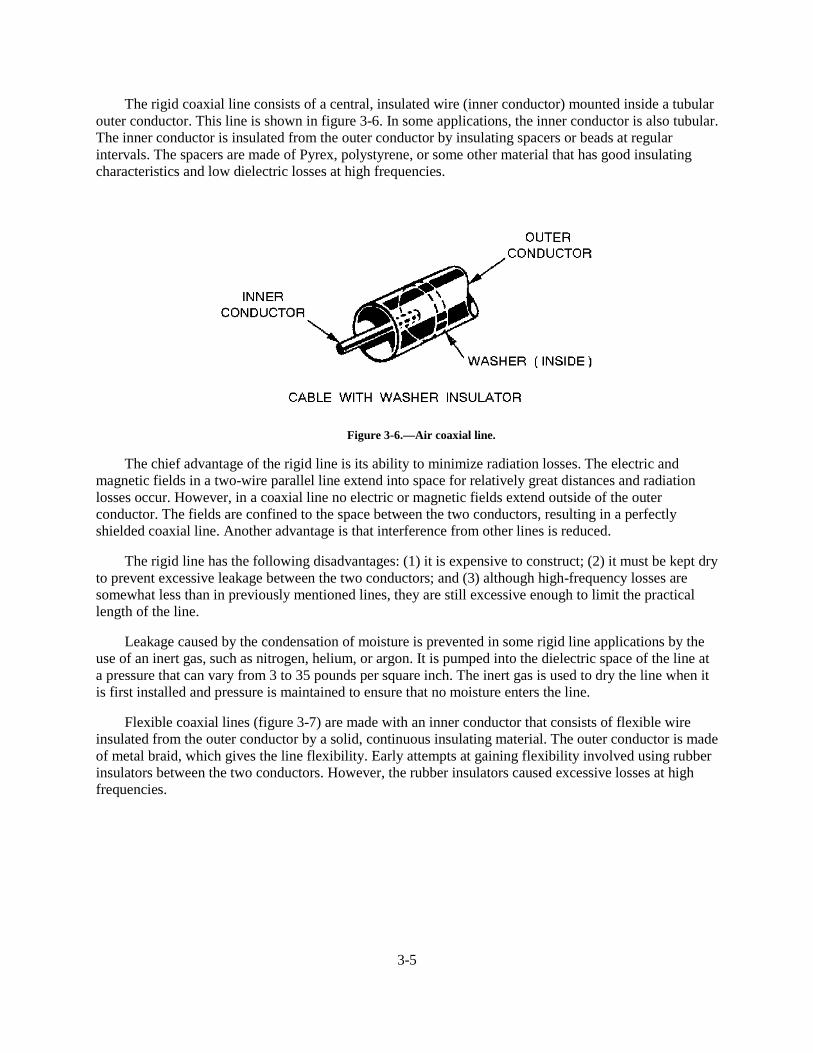
3-5
The rigid coaxial line consists of a central, insulated wire (inner conductor) mounted inside a tubularouter conductor. This line is shown in figure 3-6. In some applications, the inner conductor is also tubular.The inner conductor is insulated from the outer conductor by insulating spacers or beads at regularintervals. The spacers are made of Pyrex, polystyrene, or some other material that has good insulatingcharacteristics and low dielectric losses at high frequencies.
Figure 3-6.—Air coaxial line.
The chief advantage of the rigid line is its ability to minimize radiation losses. The electric andmagnetic fields in a two-wire parallel line extend into space for relatively great distances and radiationlosses occur. However, in a coaxial line no electric or magnetic fields extend outside of the outerconductor. The fields are confined to the space between the two conductors, resulting in a perfectlyshielded coaxial line. Another advantage is that interference from other lines is reduced.
The rigid line has the following disadvantages: (1) it is expensive to construct; (2) it must be kept dryto prevent excessive leakage between the two conductors; and (3) although high-frequency losses aresomewhat less than in previously mentioned lines, they are still excessive enough to limit the practicallength of the line.
Leakage caused by the condensation of moisture is prevented in some rigid line applications by theuse of an inert gas, such as nitrogen, helium, or argon. It is pumped into the dielectric space of the line ata pressure that can vary from 3 to 35 pounds per square inch. The inert gas is used to dry the line when itis first installed and pressure is maintained to ensure that no moisture enters the line.
Flexible coaxial lines (figure 3-7) are made with an inner conductor that consists of flexible wireinsulated from the outer conductor by a solid, continuous insulating material. The outer conductor is madeof metal braid, which gives the line flexibility. Early attempts at gaining flexibility involved using rubberinsulators between the two conductors. However, the rubber insulators caused excessive losses at highfrequencies.
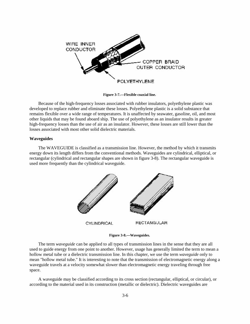
3-6
Figure 3-7.—Flexible coaxial line.
Because of the high-frequency losses associated with rubber insulators, polyethylene plastic wasdeveloped to replace rubber and eliminate these losses. Polyethylene plastic is a solid substance thatremains flexible over a wide range of temperatures. It is unaffected by seawater, gasoline, oil, and mostother liquids that may be found aboard ship. The use of polyethylene as an insulator results in greaterhigh-frequency losses than the use of air as an insulator. However, these losses are still lower than thelosses associated with most other solid dielectric materials.
Waveguides
The WAVEGUIDE is classified as a transmission line. However, the method by which it transmitsenergy down its length differs from the conventional methods. Waveguides are cylindrical, elliptical, orrectangular (cylindrical and rectangular shapes are shown in figure 3-8). The rectangular waveguide isused more frequently than the cylindrical waveguide.
Figure 3-8.—Waveguides.
The term waveguide can be applied to all types of transmission lines in the sense that they are allused to guide energy from one point to another. However, usage has generally limited the term to mean ahollow metal tube or a dielectric transmission line. In this chapter, we use the term waveguide only tomean "hollow metal tube." It is interesting to note that the transmission of electromagnetic energy along awaveguide travels at a velocity somewhat slower than electromagnetic energy traveling through freespace.
A waveguide may be classified according to its cross section (rectangular, elliptical, or circular), oraccording to the material used in its construction (metallic or dielectric). Dielectric waveguides are
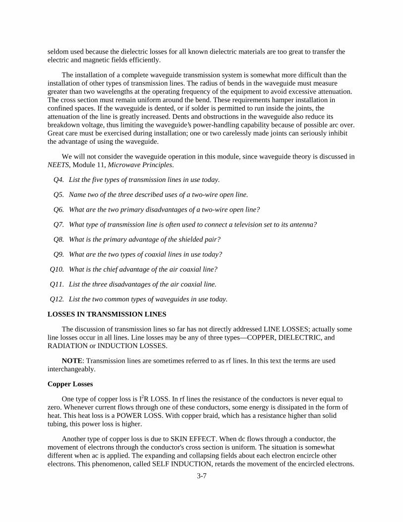
3-7
seldom used because the dielectric losses for all known dielectric materials are too great to transfer theelectric and magnetic fields efficiently.
The installation of a complete waveguide transmission system is somewhat more difficult than theinstallation of other types of transmission lines. The radius of bends in the waveguide must measuregreater than two wavelengths at the operating frequency of the equipment to avoid excessive attenuation.The cross section must remain uniform around the bend. These requirements hamper installation inconfined spaces. If the waveguide is dented, or if solder is permitted to run inside the joints, theattenuation of the line is greatly increased. Dents and obstructions in the waveguide also reduce itsbreakdown voltage, thus limiting the waveguide’s power-handling capability because of possible arc over.Great care must be exercised during installation; one or two carelessly made joints can seriously inhibitthe advantage of using the waveguide.
We will not consider the waveguide operation in this module, since waveguide theory is discussed inNEETS, Module 11, Microwave Principles.
Q4. List the five types of transmission lines in use today.
Q5. Name two of the three described uses of a two-wire open line.
Q6. What are the two primary disadvantages of a two-wire open line?
Q7. What type of transmission line is often used to connect a television set to its antenna?
Q8. What is the primary advantage of the shielded pair?
Q9. What are the two types of coaxial lines in use today?
Q10. What is the chief advantage of the air coaxial line?
Q11. List the three disadvantages of the air coaxial line.
Q12. List the two common types of waveguides in use today.
LOSSES IN TRANSMISSION LINES
The discussion of transmission lines so far has not directly addressed LINE LOSSES; actually someline losses occur in all lines. Line losses may be any of three types—COPPER, DIELECTRIC, andRADIATION or INDUCTION LOSSES.
NOTE: Transmission lines are sometimes referred to as rf lines. In this text the terms are usedinterchangeably.
Copper Losses
One type of copper loss is I2R LOSS. In rf lines the resistance of the conductors is never equal tozero. Whenever current flows through one of these conductors, some energy is dissipated in the form ofheat. This heat loss is a POWER LOSS. With copper braid, which has a resistance higher than solidtubing, this power loss is higher.
Another type of copper loss is due to SKIN EFFECT. When dc flows through a conductor, themovement of electrons through the conductor's cross section is uniform. The situation is somewhatdifferent when ac is applied. The expanding and collapsing fields about each electron encircle otherelectrons. This phenomenon, called SELF INDUCTION, retards the movement of the encircled electrons.
3-8
The flux density at the center is so great that electron movement at this point is reduced. As frequency isincreased, the opposition to the flow of current in the center of the wire increases. Current in the center ofthe wire becomes smaller and most of the electron flow is on the wire surface. When the frequencyapplied is 100 megahertz or higher, the electron movement in the center is so small that the center of thewire could be removed without any noticeable effect on current. You should be able to see that theeffective cross-sectional area decreases as the frequency increases. Since resistance is inverselyproportional to the cross-sectional area, the resistance will increase as the frequency is increased. Also,since power loss increases as resistance increases, power losses increase with an increase in frequencybecause of skin effect.
Copper losses can be minimized and conductivity increased in an rf line by plating the line withsilver. Since silver is a better conductor than copper, most of the current will flow through the silver layer.The tubing then serves primarily as a mechanical support.
Dielectric Losses
DIELECTRIC LOSSES result from the heating effect on the dielectric material between theconductors. Power from the source is used in heating the dielectric. The heat produced is dissipated intothe surrounding medium. When there is no potential difference between two conductors, the atoms in thedielectric material between them are normal and the orbits of the electrons are circular. When there is apotential difference between two conductors, the orbits of the electrons change. The excessive negativecharge on one conductor repels electrons on the dielectric toward the positive conductor and thus distortsthe orbits of the electrons. A change in the path of electrons requires more energy, introducing a powerloss.
The atomic structure of rubber is more difficult to distort than the structure of some other dielectricmaterials. The atoms of materials, such as polyethylene, distort easily. Therefore, polyethylene is oftenused as a dielectric because less power is consumed when its electron orbits are distorted.
Radiation and Induction Losses
RADIATION and INDUCTION LOSSES are similar in that both are caused by the fieldssurrounding the conductors. Induction losses occur when the electromagnetic field about a conductor cutsthrough any nearby metallic object and a current is induced in that object. As a result, power is dissipatedin the object and is lost.
Radiation losses occur because some magnetic lines of force about a conductor do not return to theconductor when the cycle alternates. These lines of force are projected into space as radiation and thisresults in power losses. That is, power is supplied by the source, but is not available to the load.
Q13. What are the three types of line losses associated with transmission lines?
Q14. Losses caused by skin effect and the I 2 R (power) loss are classified as what type of loss?
Q15. What types of losses cause the dielectric material between the conductors to be heated?
LENGTH OF A TRANSMISSION LINE
A transmission line is considered to be electrically short when its physical length is short comparedWR�D�TXDUWHU�ZDYHOHQJWK����� ��RI�WKH�HQHUJ\�LW�LV�WR�FDUU\�
NOTE: In this module, for ease of reading, the value of the wavelength will be spelled out in somecases, and in other cases, the numerical value will be used.
3-9
A transmission line is electrically long when its physical length is long compared to a quarter-wavelength of the energy it is to carry. You must understand that the terms "short" and "long" are relativeones. For example, a line that has a physical length of 3 meters (approximately 10 feet) is consideredquite short electrically if it transmits a radio frequency of 30 kilohertz. On the other hand, the sametransmission line is considered electrically long if it transmits a frequency of 30,000 megahertz.
To show the difference in physical and electrical lengths of the lines mentioned above, compute thewavelength of the two frequencies, taking the 30-kilohertz example first:
Now, computing the wavelength for the line carrying 30,000 megahertz:
Thus, you can see that a 3-meter line is electrically very short for a frequency of 30 kilohertz. Also,the 3-meter line is electrically very long for a frequency of 30,000 megahertz.
When power is applied to a very short transmission line, practically all of it reaches the load at theoutput end of the line. This very short transmission line is usually considered to have practically noelectrical properties of its own, except for a small amount of resistance.
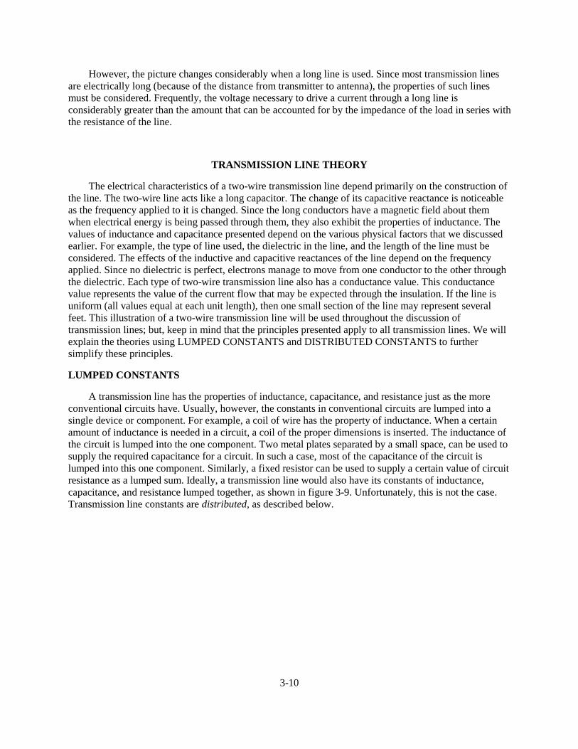
3-10
However, the picture changes considerably when a long line is used. Since most transmission linesare electrically long (because of the distance from transmitter to antenna), the properties of such linesmust be considered. Frequently, the voltage necessary to drive a current through a long line isconsiderably greater than the amount that can be accounted for by the impedance of the load in series withthe resistance of the line.
TRANSMISSION LINE THEORY
The electrical characteristics of a two-wire transmission line depend primarily on the construction ofthe line. The two-wire line acts like a long capacitor. The change of its capacitive reactance is noticeableas the frequency applied to it is changed. Since the long conductors have a magnetic field about themwhen electrical energy is being passed through them, they also exhibit the properties of inductance. Thevalues of inductance and capacitance presented depend on the various physical factors that we discussedearlier. For example, the type of line used, the dielectric in the line, and the length of the line must beconsidered. The effects of the inductive and capacitive reactances of the line depend on the frequencyapplied. Since no dielectric is perfect, electrons manage to move from one conductor to the other throughthe dielectric. Each type of two-wire transmission line also has a conductance value. This conductancevalue represents the value of the current flow that may be expected through the insulation. If the line isuniform (all values equal at each unit length), then one small section of the line may represent severalfeet. This illustration of a two-wire transmission line will be used throughout the discussion oftransmission lines; but, keep in mind that the principles presented apply to all transmission lines. We willexplain the theories using LUMPED CONSTANTS and DISTRIBUTED CONSTANTS to furthersimplify these principles.
LUMPED CONSTANTS
A transmission line has the properties of inductance, capacitance, and resistance just as the moreconventional circuits have. Usually, however, the constants in conventional circuits are lumped into asingle device or component. For example, a coil of wire has the property of inductance. When a certainamount of inductance is needed in a circuit, a coil of the proper dimensions is inserted. The inductance ofthe circuit is lumped into the one component. Two metal plates separated by a small space, can be used tosupply the required capacitance for a circuit. In such a case, most of the capacitance of the circuit islumped into this one component. Similarly, a fixed resistor can be used to supply a certain value of circuitresistance as a lumped sum. Ideally, a transmission line would also have its constants of inductance,capacitance, and resistance lumped together, as shown in figure 3-9. Unfortunately, this is not the case.Transmission line constants are distributed, as described below.

3-11
Figure 3-9.—Equivalent circuit of a two-wire transmission line.
DISTRIBUTED CONSTANTS
Transmission line constants, called distributed constants, are spread along the entire length of thetransmission line and cannot be distinguished separately. The amount of inductance, capacitance, andresistance depends on the length of the line, the size of the conducting wires, the spacing between thewires, and the dielectric (air or insulating medium) between the wires. The following paragraphs will beuseful to you as you study distributed constants on a transmission line.
Inductance of a Transmission Line
When current flows through a wire, magnetic lines of force are set up around the wire. As the currentincreases and decreases in amplitude, the field around the wire expands and collapses accordingly. Theenergy produced by the magnetic lines of force collapsing back into the wire tends to keep the currentflowing in the same direction. This represents a certain amount of inductance, which is expressed inmicrohenrys per unit length. Figure 3-10 illustrates the inductance and magnetic fields of a transmissionline.
Figure 3-10.—Distributed inductance
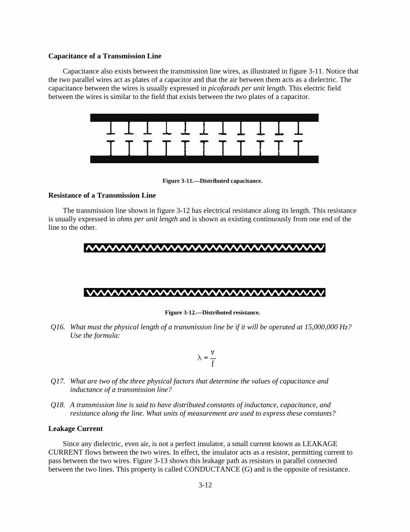
3-12
Capacitance of a Transmission Line
Capacitance also exists between the transmission line wires, as illustrated in figure 3-11. Notice thatthe two parallel wires act as plates of a capacitor and that the air between them acts as a dielectric. Thecapacitance between the wires is usually expressed in picofarads per unit length. This electric fieldbetween the wires is similar to the field that exists between the two plates of a capacitor.
Figure 3-11.—Distributed capacitance.
Resistance of a Transmission Line
The transmission line shown in figure 3-12 has electrical resistance along its length. This resistanceis usually expressed in ohms per unit length and is shown as existing continuously from one end of theline to the other.
Figure 3-12.—Distributed resistance.
Q16. What must the physical length of a transmission line be if it will be operated at 15,000,000 Hz?Use the formula:
Q17. What are two of the three physical factors that determine the values of capacitance andinductance of a transmission line?
Q18. A transmission line is said to have distributed constants of inductance, capacitance, andresistance along the line. What units of measurement are used to express these constants?
Leakage Current
Since any dielectric, even air, is not a perfect insulator, a small current known as LEAKAGECURRENT flows between the two wires. In effect, the insulator acts as a resistor, permitting current topass between the two wires. Figure 3-13 shows this leakage path as resistors in parallel connectedbetween the two lines. This property is called CONDUCTANCE (G) and is the opposite of resistance.
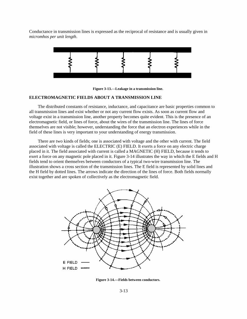
3-13
Conductance in transmission lines is expressed as the reciprocal of resistance and is usually given inmicromhos per unit length.
Figure 3-13.—Leakage in a transmission line.
ELECTROMAGNETIC FIELDS ABOUT A TRANSMISSION LINE
The distributed constants of resistance, inductance, and capacitance are basic properties common toall transmission lines and exist whether or not any current flow exists. As soon as current flow andvoltage exist in a transmission line, another property becomes quite evident. This is the presence of anelectromagnetic field, or lines of force, about the wires of the transmission line. The lines of forcethemselves are not visible; however, understanding the force that an electron experiences while in thefield of these lines is very important to your understanding of energy transmission.
There are two kinds of fields; one is associated with voltage and the other with current. The fieldassociated with voltage is called the ELECTRIC (E) FIELD. It exerts a force on any electric chargeplaced in it. The field associated with current is called a MAGNETIC (H) FIELD, because it tends toexert a force on any magnetic pole placed in it. Figure 3-14 illustrates the way in which the E fields and Hfields tend to orient themselves between conductors of a typical two-wire transmission line. Theillustration shows a cross section of the transmission lines. The E field is represented by solid lines andthe H field by dotted lines. The arrows indicate the direction of the lines of force. Both fields normallyexist together and are spoken of collectively as the electromagnetic field.
Figure 3-14.—Fields between conductors.

3-14
CHARACTERISTIC IMPEDANCE OF A TRANSMISSION LINE
You learned earlier that the maximum (and most efficient) transfer of electrical energy takes placewhen the source impedance is matched to the load impedance. This fact is very important in the study oftransmission lines and antennas. If the characteristic impedance of the transmission line and the loadimpedance are equal, energy from the transmitter will travel down the transmission line to the antennawith no power loss caused by reflection.
Definition and Symbols
Every transmission line possesses a certain CHARACTERISTIC IMPEDANCE, usually designatedas Z0. Z0 is the ratio of E to I at every point along the line. If a load equal to the characteristic impedanceis placed at the output end of any length of line, the same impedance will appear at the input terminals ofthe line. The characteristic impedance is the only value of impedance for any given type and size of linethat acts in this way. The characteristic impedance determines the amount of current that can flow when agiven voltage is applied to an infinitely long line. Characteristic impedance is comparable to theresistance that determines the amount of current that flows in a dc circuit.
In a previous discussion, lumped and distributed constants were explained. Figure 3-15, view A,shows the properties of resistance, inductance, capacitance, and conductance combined in a short sectionof two-wire transmission line. The illustration shows the evenly distributed capacitance as a singlelumped capacitor and the distributed conductance as a lumped leakage path. Lumped values may be usedfor transmission line calculations if the physical length of the line is very short compared to thewavelength of energy being transmitted. Figure 3-15, view B, shows all four properties lumped togetherand represented by their conventional symbols.
Figure 3-15.—Short section of two-wire transmission line and equivalent circuit.
Q19. Describe the leakage current in a transmission line and in what unit it is expressed.
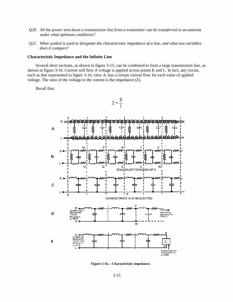
3-15
Q20. All the power sent down a transmission line from a transmitter can be transferred to an antennaunder what optimum conditions?
Q21. What symbol is used to designate the characteristic impedance of a line, and what two variablesdoes it compare?
Characteristic Impedance and the Infinite Line
Several short sections, as shown in figure 3-15, can be combined to form a large transmission line, asshown in figure 3-16. Current will flow if voltage is applied across points K and L. In fact, any circuit,such as that represented in figure 3-16, view A, has a certain current flow for each value of appliedvoltage. The ratio of the voltage to the current is the impedance (Z).
Recall that:
Figure 3-16.—Characteristic impedance.
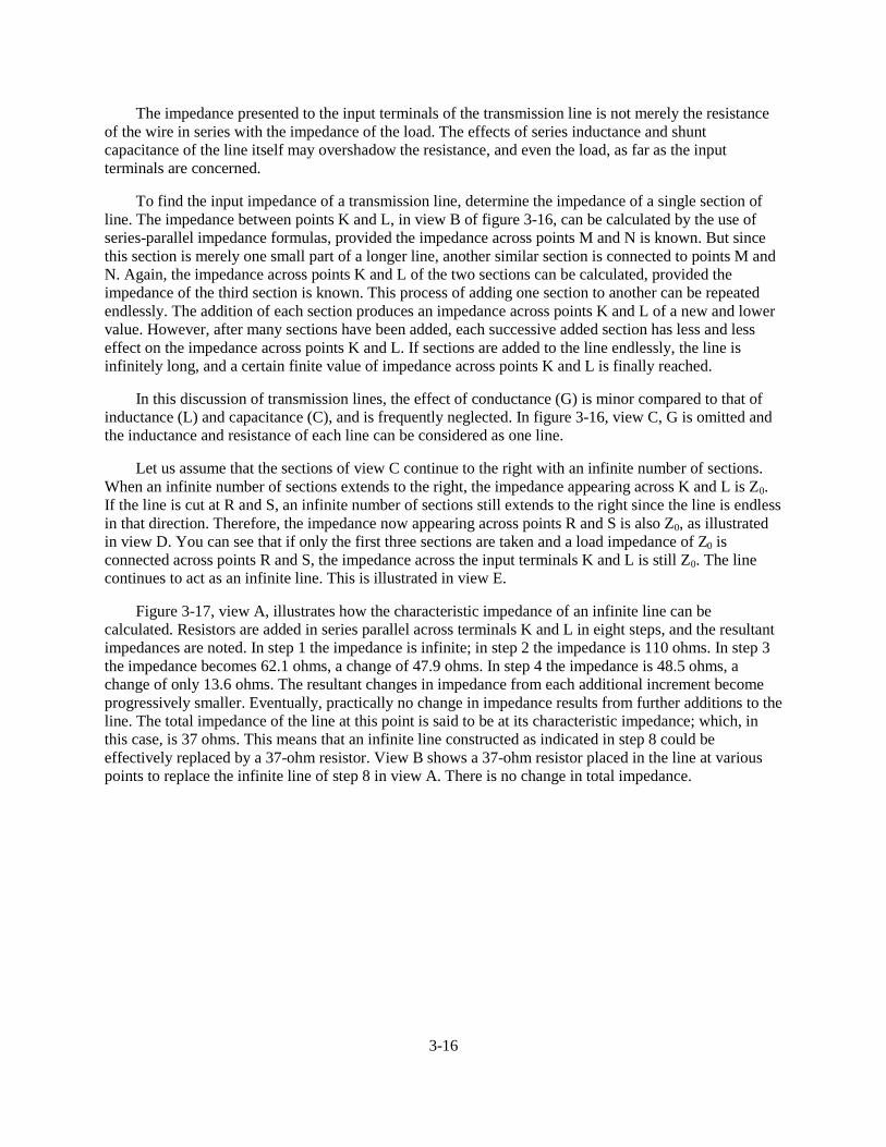
3-16
The impedance presented to the input terminals of the transmission line is not merely the resistanceof the wire in series with the impedance of the load. The effects of series inductance and shuntcapacitance of the line itself may overshadow the resistance, and even the load, as far as the inputterminals are concerned.
To find the input impedance of a transmission line, determine the impedance of a single section ofline. The impedance between points K and L, in view B of figure 3-16, can be calculated by the use ofseries-parallel impedance formulas, provided the impedance across points M and N is known. But sincethis section is merely one small part of a longer line, another similar section is connected to points M andN. Again, the impedance across points K and L of the two sections can be calculated, provided theimpedance of the third section is known. This process of adding one section to another can be repeatedendlessly. The addition of each section produces an impedance across points K and L of a new and lowervalue. However, after many sections have been added, each successive added section has less and lesseffect on the impedance across points K and L. If sections are added to the line endlessly, the line isinfinitely long, and a certain finite value of impedance across points K and L is finally reached.
In this discussion of transmission lines, the effect of conductance (G) is minor compared to that ofinductance (L) and capacitance (C), and is frequently neglected. In figure 3-16, view C, G is omitted andthe inductance and resistance of each line can be considered as one line.
Let us assume that the sections of view C continue to the right with an infinite number of sections.When an infinite number of sections extends to the right, the impedance appearing across K and L is Z0.If the line is cut at R and S, an infinite number of sections still extends to the right since the line is endlessin that direction. Therefore, the impedance now appearing across points R and S is also Z0, as illustratedin view D. You can see that if only the first three sections are taken and a load impedance of Z0 isconnected across points R and S, the impedance across the input terminals K and L is still Z0. The linecontinues to act as an infinite line. This is illustrated in view E.
Figure 3-17, view A, illustrates how the characteristic impedance of an infinite line can becalculated. Resistors are added in series parallel across terminals K and L in eight steps, and the resultantimpedances are noted. In step 1 the impedance is infinite; in step 2 the impedance is 110 ohms. In step 3the impedance becomes 62.1 ohms, a change of 47.9 ohms. In step 4 the impedance is 48.5 ohms, achange of only 13.6 ohms. The resultant changes in impedance from each additional increment becomeprogressively smaller. Eventually, practically no change in impedance results from further additions to theline. The total impedance of the line at this point is said to be at its characteristic impedance; which, inthis case, is 37 ohms. This means that an infinite line constructed as indicated in step 8 could beeffectively replaced by a 37-ohm resistor. View B shows a 37-ohm resistor placed in the line at variouspoints to replace the infinite line of step 8 in view A. There is no change in total impedance.
3-17
Figure 3-17.—Termination of a line.
In figure 3-17, resistors were used to show impedance characteristics for the sake of simplicity.Figuring the actual impedance of a line having reactance is very similar, with inductance taking the placeof the series resistors and capacitance taking the place of the shunt resistors. The characteristic impedanceof lines in actual use normally lies between 50 and 600 ohms.
When a transmission line is "short” compared to the length of the radio-frequency waves it carries,the opposition presented to the input terminals is determined primarily by the load impedance. A smallamount of power is dissipated in overcoming the resistance of the line. However, when the line is "long”and the load is an incorrect impedance, the voltages necessary to drive a given amount of current throughthe line cannot be accounted for by considering just the impedance of the load in series with the
3-18
impedance of the line. The line has properties other than resistance that affect input impedance. Theseproperties are inductance in series with the line, capacitance across the line, resistance leakage pathsacross the line, and certain radiation losses.
Q22. What is the range of the characteristic impedance of lines used in actual practice?
VOLTAGE CHANGE ALONG A TRANSMISSION LINE
Let us summarize what we have just discussed. In an electric circuit, energy is stored in electric andmagnetic fields. These fields must be brought to the load to transmit that energy. At the load, energycontained in the fields is converted to the desired form of energy.
Transmission of Energy
When the load is connected directly to the source of energy, or when the transmission line is short,problems concerning current and voltage can be solved by applying Ohm’s law. When the transmissionline becomes long enough so the time difference between a change occurring at the generator and thechange appearing at the load becomes appreciable, analysis of the transmission line becomes important.
Dc Applied to a Transmission Line
In figure 3-18, a battery is connected through a relatively long two-wire transmission line to a load atthe far end of the line. At the instant the switch is closed, neither current nor voltage exists on the line.When the switch is closed, point A becomes a positive potential, and point B becomes negative. Thesepoints of difference in potential move down the line. However, as the initial points of potential leavepoints A and B, they are followed by new points of difference in potential which the battery adds at A andB. This is merely saying that the battery maintains a constant potential difference between points A andB. A short time after the switch is closed, the initial points of difference in potential have reached pointsA’ and B’; the wire sections from points A to A’ and points B to B’ are at the same potential as A and B,respectively. The points of charge are represented by plus (+) and minus (-) signs along the wires. Thedirections of the currents in the wires are represented by the arrowheads on the line, and the direction oftravel is indicated by an arrow below the line. Conventional lines of force represent the electric field thatexists between the opposite kinds of charge on the wire sections from A to A’ and B to B’. Crosses (tailsof arrows) indicate the magnetic field created by the electric field moving down the line. The movingelectric field and the accompanying magnetic field constitute an electromagnetic wave that is movingfrom the generator (battery) toward the load. This wave travels at approximately the speed of light in freespace. The energy reaching the load is equal to that developed at the battery (assuming there are no lossesin the transmission line). If the load absorbs all of the energy, the current and voltage will be evenlydistributed along the line.

3-19
Figure 3-18.—Dc voltage applied to a line.
Ac Applied to a Transmission Line
When the battery of figure 3-18 is replaced by an ac generator (fig. 3-19), each successiveinstantaneous value of the generator voltage is propagated down the line at the speed of light. The actionis similar to the wave created by the battery except that the applied voltage is sinusoidal instead ofconstant. Assume that the switch is closed at the moment the generator voltage is passing through zeroand that the next half cycle makes point A positive. At the end of one cycle of generator voltage, thecurrent and voltage distribution will be as shown in figure 3-19.
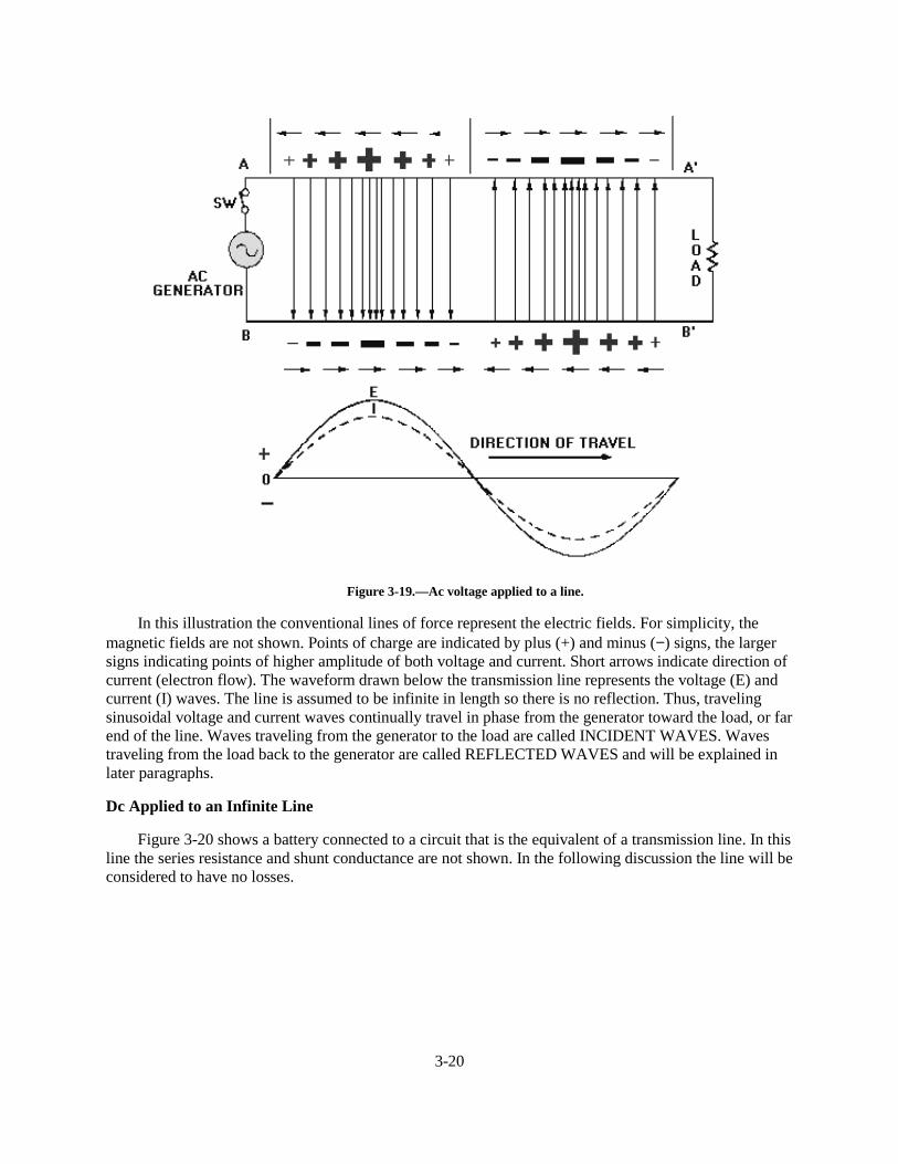
3-20
Figure 3-19.—Ac voltage applied to a line.
In this illustration the conventional lines of force represent the electric fields. For simplicity, themagnetic fields are not shown. Points of charge are indicated by plus (+) and minus (−) signs, the largersigns indicating points of higher amplitude of both voltage and current. Short arrows indicate direction ofcurrent (electron flow). The waveform drawn below the transmission line represents the voltage (E) andcurrent (I) waves. The line is assumed to be infinite in length so there is no reflection. Thus, travelingsinusoidal voltage and current waves continually travel in phase from the generator toward the load, or farend of the line. Waves traveling from the generator to the load are called INCIDENT WAVES. Wavestraveling from the load back to the generator are called REFLECTED WAVES and will be explained inlater paragraphs.
Dc Applied to an Infinite Line
Figure 3-20 shows a battery connected to a circuit that is the equivalent of a transmission line. In thisline the series resistance and shunt conductance are not shown. In the following discussion the line will beconsidered to have no losses.
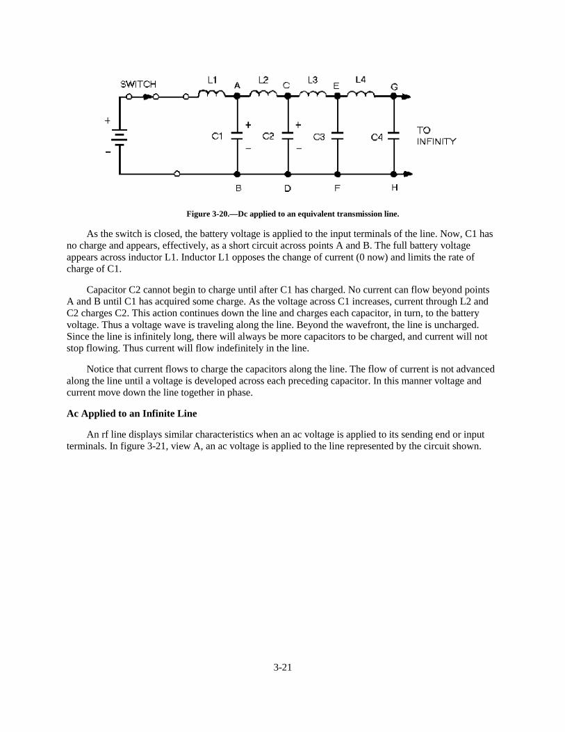
3-21
Figure 3-20.—Dc applied to an equivalent transmission line.
As the switch is closed, the battery voltage is applied to the input terminals of the line. Now, C1 hasno charge and appears, effectively, as a short circuit across points A and B. The full battery voltageappears across inductor L1. Inductor L1 opposes the change of current (0 now) and limits the rate ofcharge of C1.
Capacitor C2 cannot begin to charge until after C1 has charged. No current can flow beyond pointsA and B until C1 has acquired some charge. As the voltage across C1 increases, current through L2 andC2 charges C2. This action continues down the line and charges each capacitor, in turn, to the batteryvoltage. Thus a voltage wave is traveling along the line. Beyond the wavefront, the line is uncharged.Since the line is infinitely long, there will always be more capacitors to be charged, and current will notstop flowing. Thus current will flow indefinitely in the line.
Notice that current flows to charge the capacitors along the line. The flow of current is not advancedalong the line until a voltage is developed across each preceding capacitor. In this manner voltage andcurrent move down the line together in phase.
Ac Applied to an Infinite Line
An rf line displays similar characteristics when an ac voltage is applied to its sending end or inputterminals. In figure 3-21, view A, an ac voltage is applied to the line represented by the circuit shown.
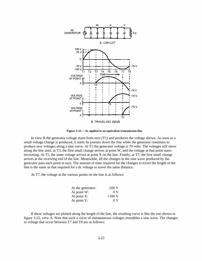
3-22
Figure 3-21.—Ac applied to an equivalent transmission line.
In view B the generator voltage starts from zero (T1) and produces the voltage shown. As soon as asmall voltage change is produced, it starts its journey down the line while the generator continues toproduce new voltages along a sine curve. At T2 the generator voltage is 70 volts. The voltages still movealong the line until, at T3, the first small change arrives at point W, and the voltage at that point startsincreasing. At T5, the same voltage arrives at point X on the line. Finally, at T7, the first small changearrives at the receiving end of the line. Meanwhile, all the changes in the sine wave produced by thegenerator pass each point in turn. The amount of time required for the changes to travel the length of theline is the same as that required for a dc voltage to travel the same distance.
At T7, the voltage at the various points on the line is as follows:
At the generator: -100 VAt point W: 0 VAt point X: +100 VAt point Y: 0 V
If these voltages are plotted along the length of the line, the resulting curve is like the one shown infigure 3-22, view A. Note that such a curve of instantaneous voltages resembles a sine wave. The changesin voltage that occur between T7 and T8 are as follows:
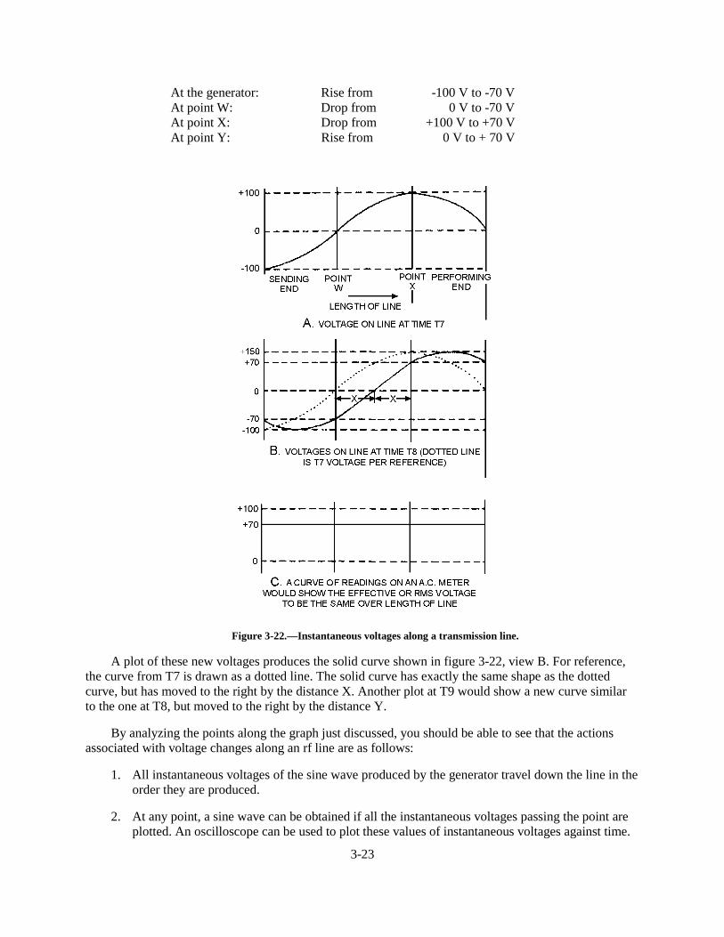
3-23
At the generator: Rise from -100 V to -70 VAt point W: Drop from 0 V to -70 VAt point X: Drop from +100 V to +70 VAt point Y: Rise from 0 V to + 70 V
Figure 3-22.—Instantaneous voltages along a transmission line.
A plot of these new voltages produces the solid curve shown in figure 3-22, view B. For reference,the curve from T7 is drawn as a dotted line. The solid curve has exactly the same shape as the dottedcurve, but has moved to the right by the distance X. Another plot at T9 would show a new curve similarto the one at T8, but moved to the right by the distance Y.
By analyzing the points along the graph just discussed, you should be able to see that the actionsassociated with voltage changes along an rf line are as follows:
1. All instantaneous voltages of the sine wave produced by the generator travel down the line in theorder they are produced.
2. At any point, a sine wave can be obtained if all the instantaneous voltages passing the point areplotted. An oscilloscope can be used to plot these values of instantaneous voltages against time.
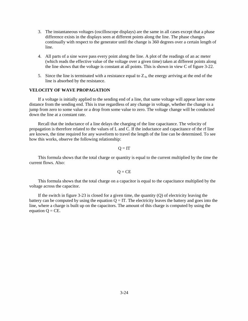
3-24
3. The instantaneous voltages (oscilloscope displays) are the same in all cases except that a phasedifference exists in the displays seen at different points along the line. The phase changescontinually with respect to the generator until the change is 360 degrees over a certain length ofline.
4. All parts of a sine wave pass every point along the line. A plot of the readings of an ac meter(which reads the effective value of the voltage over a given time) taken at different points alongthe line shows that the voltage is constant at all points. This is shown in view C of figure 3-22.
5. Since the line is terminated with a resistance equal to Z 0, the energy arriving at the end of theline is absorbed by the resistance.
VELOCITY OF WAVE PROPAGATION
If a voltage is initially applied to the sending end of a line, that same voltage will appear later somedistance from the sending end. This is true regardless of any change in voltage, whether the change is ajump from zero to some value or a drop from some value to zero. The voltage change will be conducteddown the line at a constant rate.
Recall that the inductance of a line delays the charging of the line capacitance. The velocity ofpropagation is therefore related to the values of L and C. If the inductance and capacitance of the rf lineare known, the time required for any waveform to travel the length of the line can be determined. To seehow this works, observe the following relationship:
Q = IT
This formula shows that the total charge or quantity is equal to the current multiplied by the time thecurrent flows. Also:
Q = CE
This formula shows that the total charge on a capacitor is equal to the capacitance multiplied by thevoltage across the capacitor.
If the switch in figure 3-23 is closed for a given time, the quantity (Q) of electricity leaving thebattery can be computed by using the equation Q = IT. The electricity leaves the battery and goes into theline, where a charge is built up on the capacitors. The amount of this charge is computed by using theequation Q = CE.
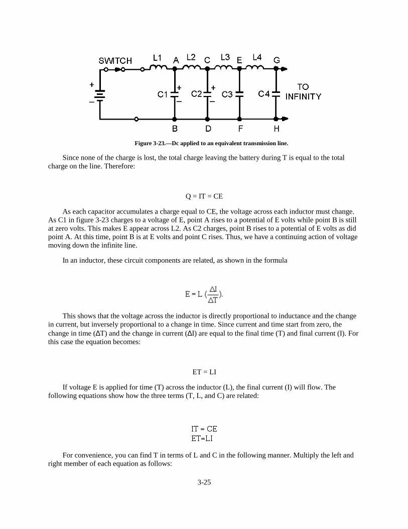
3-25
Figure 3-23.—Dc applied to an equivalent transmission line.
Since none of the charge is lost, the total charge leaving the battery during T is equal to the totalcharge on the line. Therefore:
Q = IT = CE
As each capacitor accumulates a charge equal to CE, the voltage across each inductor must change.As C1 in figure 3-23 charges to a voltage of E, point A rises to a potential of E volts while point B is stillat zero volts. This makes E appear across L2. As C2 charges, point B rises to a potential of E volts as didpoint A. At this time, point B is at E volts and point C rises. Thus, we have a continuing action of voltagemoving down the infinite line.
In an inductor, these circuit components are related, as shown in the formula
This shows that the voltage across the inductor is directly proportional to inductance and the changein current, but inversely proportional to a change in time. Since current and time start from zero, thechange in time (∆T) and the change in current (∆I) are equal to the final time (T) and final current (I). Forthis case the equation becomes:
ET = LI
If voltage E is applied for time (T) across the inductor (L), the final current (I) will flow. Thefollowing equations show how the three terms (T, L, and C) are related:
For convenience, you can find T in terms of L and C in the following manner. Multiply the left andright member of each equation as follows:

3-26
This final equation is used for finding the time required for a voltage change to travel a unit length,since L and C are given in terms of unit length. The velocity of the waves may be found by:
Where: D is the physical length of a unit
This is the rate at which the wave travels over a unit length. The units of L and C are henrys andfarads, respectively. T is in seconds per unit length and V is in unit lengths per second.
DETERMINING CHARACTERISTIC IMPEDANCE
As previously discussed, an infinite transmission line exhibits a definite input impedance. Thisimpedance is the CHARACTERISTIC IMPEDANCE and is independent of line length. The exact valueof this impedance is the ratio of the input voltage to the input current. If the line is infinite or is terminatedin a resistance equal to the characteristic impedance, voltage and current waves traveling the line are inphase. To determine the characteristic impedance or voltage-to-current ratio, use the following procedure:
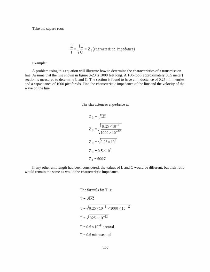
3-27
Take the square root:
Example:
A problem using this equation will illustrate how to determine the characteristics of a transmissionline. Assume that the line shown in figure 3-23 is 1000 feet long. A 100-foot (approximately 30.5 meter)section is measured to determine L and C. The section is found to have an inductance of 0.25 millihenriesand a capacitance of 1000 picofarads. Find the characteristic impedance of the line and the velocity of thewave on the line.
If any other unit length had been considered, the values of L and C would be different, but their ratiowould remain the same as would the characteristic impedance.
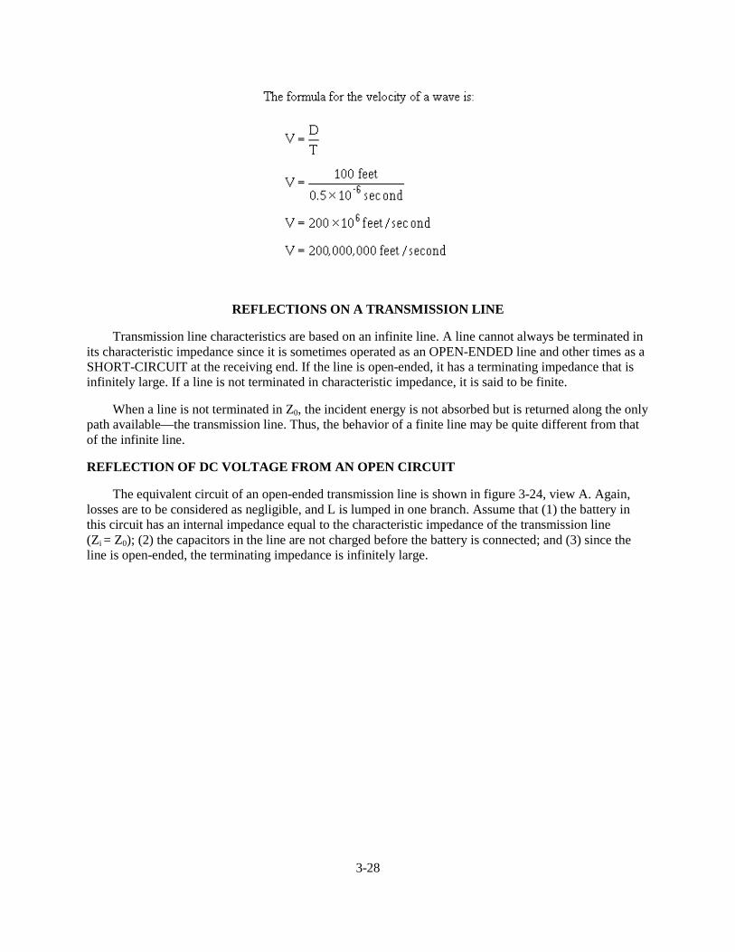
3-28
REFLECTIONS ON A TRANSMISSION LINE
Transmission line characteristics are based on an infinite line. A line cannot always be terminated inits characteristic impedance since it is sometimes operated as an OPEN-ENDED line and other times as aSHORT-CIRCUIT at the receiving end. If the line is open-ended, it has a terminating impedance that isinfinitely large. If a line is not terminated in characteristic impedance, it is said to be finite.
When a line is not terminated in Z0, the incident energy is not absorbed but is returned along the onlypath available—the transmission line. Thus, the behavior of a finite line may be quite different from thatof the infinite line.
REFLECTION OF DC VOLTAGE FROM AN OPEN CIRCUIT
The equivalent circuit of an open-ended transmission line is shown in figure 3-24, view A. Again,losses are to be considered as negligible, and L is lumped in one branch. Assume that (1) the battery inthis circuit has an internal impedance equal to the characteristic impedance of the transmission line(Zi = Z0); (2) the capacitors in the line are not charged before the battery is connected; and (3) since theline is open-ended, the terminating impedance is infinitely large.
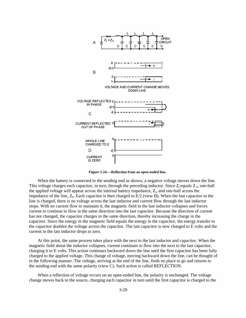
3-29
Figure 3-24.—Reflection from an open-ended line.
When the battery is connected to the sending end as shown, a negative voltage moves down the line.This voltage charges each capacitor, in turn, through the preceding inductor. Since Zi equals Z 0, one-halfthe applied voltage will appear across the internal battery impedance, Zi, and one-half across theimpedance of the line, Z0. Each capacitor is then charged to E/2 (view B). When the last capacitor in theline is charged, there is no voltage across the last inductor and current flow through the last inductorstops. With no current flow to maintain it, the magnetic field in the last inductor collapses and forcescurrent to continue to flow in the same direction into the last capacitor. Because the direction of currenthas not changed, the capacitor charges in the same direction, thereby increasing the charge in thecapacitor. Since the energy in the magnetic field equals the energy in the capacitor, the energy transfer tothe capacitor doubles the voltage across the capacitor. The last capacitor is now charged to E volts and thecurrent in the last inductor drops to zero.
At this point, the same process takes place with the next to the last inductor and capacitor. When themagnetic field about the inductor collapses, current continues to flow into the next to the last capacitor,charging it to E volts. This action continues backward down the line until the first capacitor has been fullycharged to the applied voltage. This change of voltage, moving backward down the line, can be thought ofin the following manner. The voltage, arriving at the end of the line, finds no place to go and returns tothe sending end with the same polarity (view C). Such action is called REFLECTION.
When a reflection of voltage occurs on an open-ended line, the polarity is unchanged. The voltagechange moves back to the source, charging each capacitor in turn until the first capacitor is charged to the
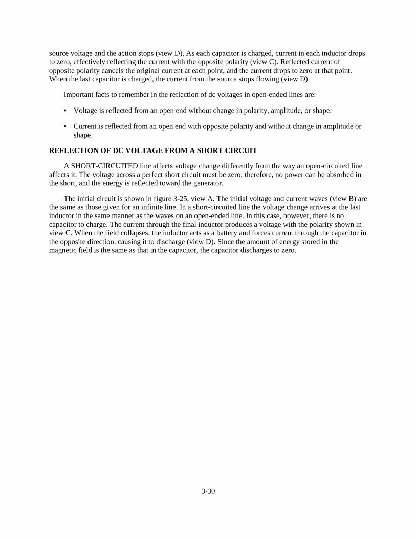
3-30
source voltage and the action stops (view D). As each capacitor is charged, current in each inductor dropsto zero, effectively reflecting the current with the opposite polarity (view C). Reflected current ofopposite polarity cancels the original current at each point, and the current drops to zero at that point.When the last capacitor is charged, the current from the source stops flowing (view D).
Important facts to remember in the reflection of dc voltages in open-ended lines are:
• Voltage is reflected from an open end without change in polarity, amplitude, or shape.
• Current is reflected from an open end with opposite polarity and without change in amplitude orshape.
REFLECTION OF DC VOLTAGE FROM A SHORT CIRCUIT
A SHORT-CIRCUITED line affects voltage change differently from the way an open-circuited lineaffects it. The voltage across a perfect short circuit must be zero; therefore, no power can be absorbed inthe short, and the energy is reflected toward the generator.
The initial circuit is shown in figure 3-25, view A. The initial voltage and current waves (view B) arethe same as those given for an infinite line. In a short-circuited line the voltage change arrives at the lastinductor in the same manner as the waves on an open-ended line. In this case, however, there is nocapacitor to charge. The current through the final inductor produces a voltage with the polarity shown inview C. When the field collapses, the inductor acts as a battery and forces current through the capacitor inthe opposite direction, causing it to discharge (view D). Since the amount of energy stored in themagnetic field is the same as that in the capacitor, the capacitor discharges to zero.
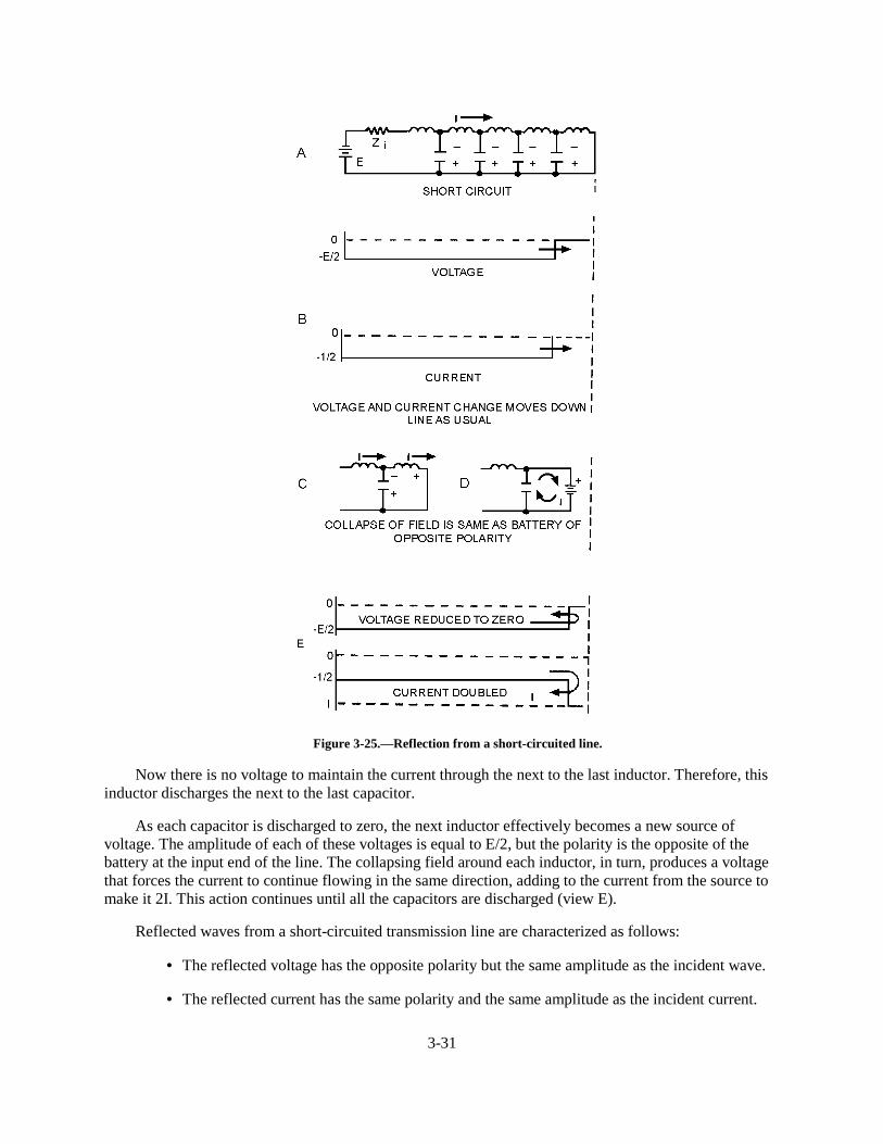
3-31
Figure 3-25.—Reflection from a short-circuited line.
Now there is no voltage to maintain the current through the next to the last inductor. Therefore, thisinductor discharges the next to the last capacitor.
As each capacitor is discharged to zero, the next inductor effectively becomes a new source ofvoltage. The amplitude of each of these voltages is equal to E/2, but the polarity is the opposite of thebattery at the input end of the line. The collapsing field around each inductor, in turn, produces a voltagethat forces the current to continue flowing in the same direction, adding to the current from the source tomake it 2I. This action continues until all the capacitors are discharged (view E).
Reflected waves from a short-circuited transmission line are characterized as follows:
• The reflected voltage has the opposite polarity but the same amplitude as the incident wave.
• The reflected current has the same polarity and the same amplitude as the incident current.
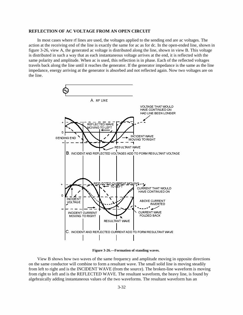
3-32
REFLECTION OF AC VOLTAGE FROM AN OPEN CIRCUIT
In most cases where rf lines are used, the voltages applied to the sending end are ac voltages. Theaction at the receiving end of the line is exactly the same for ac as for dc. In the open-ended line, shown infigure 3-26, view A, the generated ac voltage is distributed along the line, shown in view B. This voltageis distributed in such a way that as each instantaneous voltage arrives at the end, it is reflected with thesame polarity and amplitude. When ac is used, this reflection is in phase. Each of the reflected voltagestravels back along the line until it reaches the generator. If the generator impedance is the same as the lineimpedance, energy arriving at the generator is absorbed and not reflected again. Now two voltages are onthe line.
Figure 3-26.—Formation of standing waves.
View B shows how two waves of the same frequency and amplitude moving in opposite directionson the same conductor will combine to form a resultant wave. The small solid line is moving steadilyfrom left to right and is the INCIDENT WAVE (from the source). The broken-line waveform is movingfrom right to left and is the REFLECTED WAVE. The resultant waveform, the heavy line, is found byalgebraically adding instantaneous values of the two waveforms. The resultant waveform has an
3-33
instantaneous peak amplitude that is equal to the sum of the peak amplitudes of the incident and reflectedwaves. Since most indicating instruments are unable to separate these voltages, they show the vector sum.An oscilloscope is usually used to study the instantaneous voltages on rf lines.
Since two waves of voltage are moving on the line, you need to know how to distinguish between thetwo. The voltages moving toward the receiving end are called INCIDENT VOLTAGES, and the wholewaveshape is called the INCIDENT WAVE. The wave moving back to the sending end after reflection iscalled the REFLECTED WAVE. The resultant voltage curve (view B of figure 3-26) shows that thevoltage is maximum at the end of the line, a condition that occurs across an open circuit.
Another step in investigating the open-circuited rf line is to see how the current waves act. Theincident current wave is the solid line in figure 3-26, view C. The voltage is represented by the dottedline. The current is in phase with the voltage while traveling toward the receiving end. At the end of theline, the current is reflected in the opposite polarity; that is, it is shifted 180 degrees in phase, but itsamplitude remains the same. The reflected wave of current is shown by dashed lines in view C. Theheavy-line curve represents the sum of the two instantaneous currents and is the resultant wave. Noticethat current is zero at the end of the line. This is reasonable, since there can be no current flow through anopen circuit.
Views B and C of figure 3-26 show the voltage and current distribution along a transmission line at apoint about 1/8 after a maximum voltage or current reaches the end of the line. Since the instantaneousvalues are continuously changing during the generation of a complete cycle, a large number of thesepictures are required to show the many different relationships.
Figure 3-27 shows the incident and reflected waveshapes at several different times. The diagrams inthe left column of figure 3-27 (representing voltage) show the incident wave and its reflection withoutchange in polarity. In figure 3-27, waveform (1), the incident wave and the reflected wave are addedalgebraically to produce the resultant wave indicated by the heavy line. In waveform (2), a zero pointpreceding the negative-going cycle of the incident wave is at the end of the line. The reflected wave andincident wave are 180 degrees out of phase at all points. (The reflected wave is the positive cycle that justpreceded the negative cycle now approaching the end of the line.) The resultant of the incident andUHIOHFWHG�ZDYHV�LV�]HUR�DW�DOO�SRLQWV�DORQJ�WKH�OLQH��,Q�ZDYHIRUP������WKH�ZDYHV�KDYH�PRYHG���� �DORQJ�WKHline; the incident wave has moved 45 degrees to the right, and the reflected wave has moved 45 degrees tothe left. The resultant voltage, shown by the heavy line, has a maximum negative at the end of the lineDQG�D�PD[LPXP�SRVLWLYH���� �IURP�WKH�HQG�RI�WKH�OLQH�
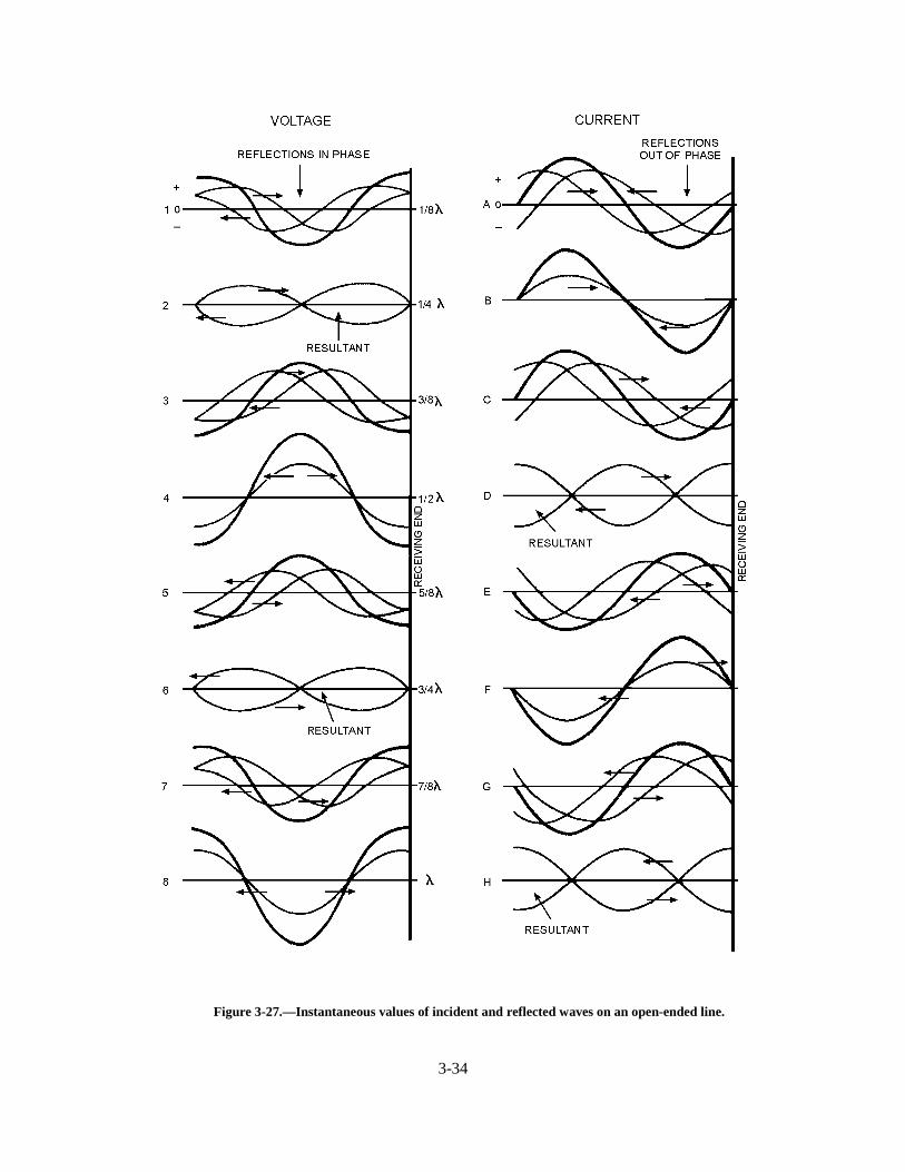
3-34
Figure 3-27.—Instantaneous values of incident and reflected waves on an open-ended line.
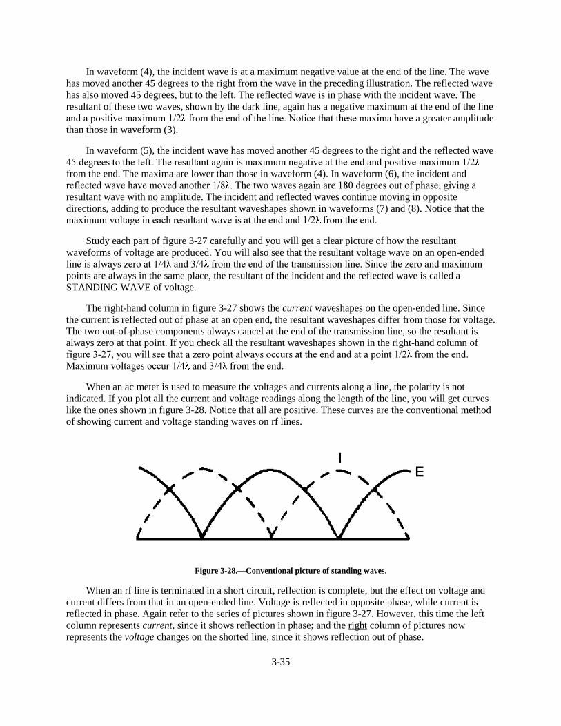
3-35
In waveform (4), the incident wave is at a maximum negative value at the end of the line. The wavehas moved another 45 degrees to the right from the wave in the preceding illustration. The reflected wavehas also moved 45 degrees, but to the left. The reflected wave is in phase with the incident wave. Theresultant of these two waves, shown by the dark line, again has a negative maximum at the end of the lineDQG�D�SRVLWLYH�PD[LPXP���� �IURP�WKH�HQG�RI�WKH�OLQH��1RWLFH�WKDW�WKHVH�PD[LPD�KDYH�a greater amplitudethan those in waveform (3).
In waveform (5), the incident wave has moved another 45 degrees to the right and the reflected wave���GHJUHHV�WR�WKH�OHIW��7KH�UHVXOWDQW�DJDLQ�LV�PD[LPXP�QHJDWLYH�DW�WKH�HQG�DQG�SRVLWLYH�PD[LPXP����from the end. The maxima are lower than those in waveform (4). In waveform (6), the incident andUHIOHFWHG�ZDYH�KDYH�PRYHG�DQRWKHU���� ��7KH�WZR�ZDYHV�DJDLQ�DUH�����GHJUHHV�RXW�RI�SKDVH��JLYLQJ�Dresultant wave with no amplitude. The incident and reflected waves continue moving in oppositedirections, adding to produce the resultant waveshapes shown in waveforms (7) and (8). Notice that thePD[LPXP�YROWDJH�LQ�HDFK�UHVXOWDQW�ZDYH�LV�DW�WKH�HQG�DQG���� �IURP�WKH�HQG�
Study each part of figure 3-27 carefully and you will get a clear picture of how the resultantwaveforms of voltage are produced. You will also see that the resultant voltage wave on an open-endedOLQH�LV�DOZD\V�]HUR�DW���� �DQG���� �IURP�WKH�HQG�RI�WKH�WUDQVPLVVLRQ�OLQH��6LQFH�WKH�]HUR�DQG�PD[LPXPpoints are always in the same place, the resultant of the incident and the reflected wave is called aSTANDING WAVE of voltage.
The right-hand column in figure 3-27 shows the current waveshapes on the open-ended line. Sincethe current is reflected out of phase at an open end, the resultant waveshapes differ from those for voltage.The two out-of-phase components always cancel at the end of the transmission line, so the resultant isalways zero at that point. If you check all the resultant waveshapes shown in the right-hand column ofILJXUH�������\RX�ZLOO�VHH�WKDW�D�]HUR�SRLQW�DOZD\V�RFFXUV�DW�WKH�HQG�DQG�DW�D�SRLQW���� �IURP�WKH�HQG�0D[LPXP�YROWDJHV�RFFXU���� �DQG���� �IURP�WKH�HQG�
When an ac meter is used to measure the voltages and currents along a line, the polarity is notindicated. If you plot all the current and voltage readings along the length of the line, you will get curveslike the ones shown in figure 3-28. Notice that all are positive. These curves are the conventional methodof showing current and voltage standing waves on rf lines.
Figure 3-28.—Conventional picture of standing waves.
When an rf line is terminated in a short circuit, reflection is complete, but the effect on voltage andcurrent differs from that in an open-ended line. Voltage is reflected in opposite phase, while current isreflected in phase. Again refer to the series of pictures shown in figure 3-27. However, this time the leftcolumn represents current, since it shows reflection in phase; and the right column of pictures nowrepresents the voltage changes on the shorted line, since it shows reflection out of phase.
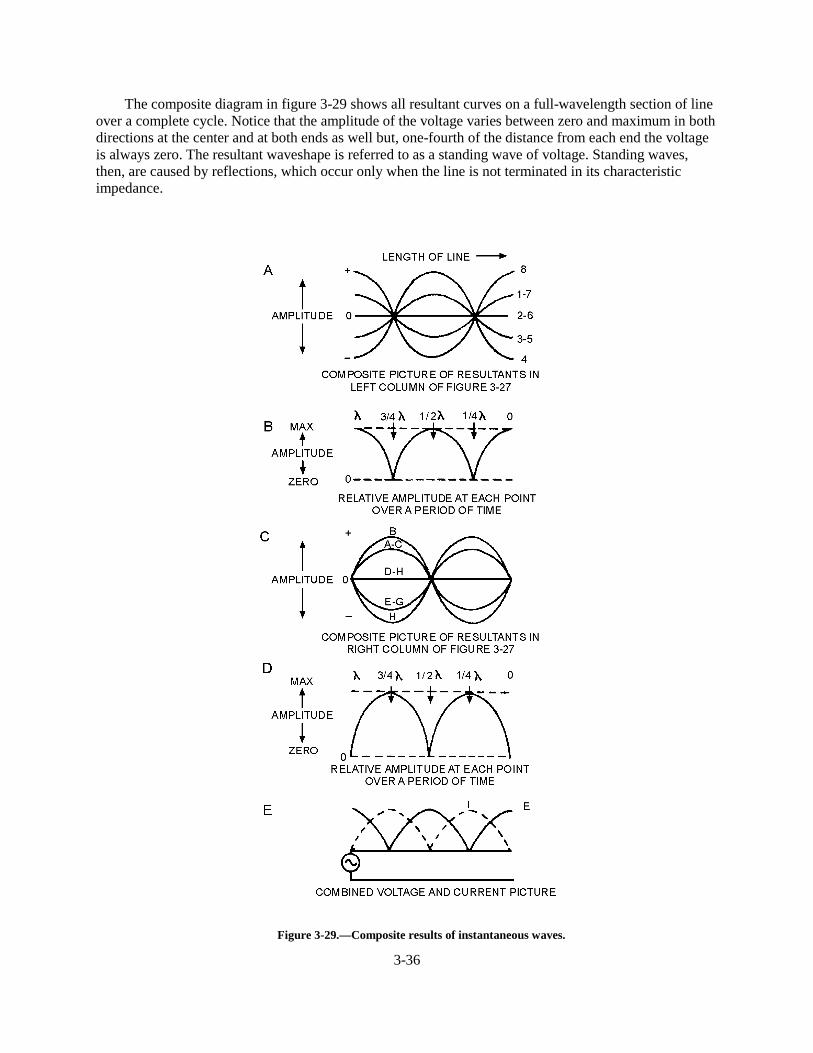
3-36
The composite diagram in figure 3-29 shows all resultant curves on a full-wavelength section of lineover a complete cycle. Notice that the amplitude of the voltage varies between zero and maximum in bothdirections at the center and at both ends as well but, one-fourth of the distance from each end the voltageis always zero. The resultant waveshape is referred to as a standing wave of voltage. Standing waves,then, are caused by reflections, which occur only when the line is not terminated in its characteristicimpedance.
Figure 3-29.—Composite results of instantaneous waves.
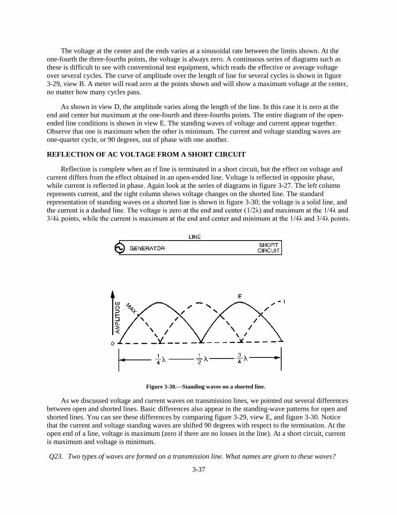
3-37
The voltage at the center and the ends varies at a sinusoidal rate between the limits shown. At theone-fourth the three-fourths points, the voltage is always zero. A continuous series of diagrams such asthese is difficult to see with conventional test equipment, which reads the effective or average voltageover several cycles. The curve of amplitude over the length of line for several cycles is shown in figure3-29, view B. A meter will read zero at the points shown and will show a maximum voltage at the center,no matter how many cycles pass.
As shown in view D, the amplitude varies along the length of the line. In this case it is zero at theend and center but maximum at the one-fourth and three-fourths points. The entire diagram of the open-ended line conditions is shown in view E. The standing waves of voltage and current appear together.Observe that one is maximum when the other is minimum. The current and voltage standing waves areone-quarter cycle, or 90 degrees, out of phase with one another.
REFLECTION OF AC VOLTAGE FROM A SHORT CIRCUIT
Reflection is complete when an rf line is terminated in a short circuit, but the effect on voltage andcurrent differs from the effect obtained in an open-ended line. Voltage is reflected in opposite phase,while current is reflected in phase. Again look at the series of diagrams in figure 3-27. The left columnrepresents current, and the right column shows voltage changes on the shorted line. The standardrepresentation of standing waves on a shorted line is shown in figure 3-30; the voltage is a solid line, andWKH�FXUUHQW�LV�D�GDVKHG�OLQH��7KH�YROWDJH�LV�]HUR�DW�WKH�HQG�DQG�FHQWHU����� ��DQG�PD[LPXP�DW�WKH���� �DQG��� �SRLQWV��ZKLOH�WKH�FXUUHQW�LV�PD[LPXP�DW�WKH�HQG�DQG�FHQWHU�DQG�PLQLPXP�DW�WKH���� �DQG���� �SRLQWV�
Figure 3-30.—Standing waves on a shorted line.
As we discussed voltage and current waves on transmission lines, we pointed out several differencesbetween open and shorted lines. Basic differences also appear in the standing-wave patterns for open andshorted lines. You can see these differences by comparing figure 3-29, view E, and figure 3-30. Noticethat the current and voltage standing waves are shifted 90 degrees with respect to the termination. At theopen end of a line, voltage is maximum (zero if there are no losses in the line). At a short circuit, currentis maximum and voltage is minimum.
Q23. Two types of waves are formed on a transmission line. What names are given to these waves?
3-38
Q24. In figure 3-27, which waveforms on the left have a resultant wave of zero, and what is indicated bythese waves?
Q25. On an open-ended transmission line, the voltage is always zero at what distance from each end ofthe line?
TERMINATING A TRANSMISSION LINE
A transmission line is either NONRESONANT or RESONANT. First, let us define the termsnonresonant lines and resonant lines. A nonresonant line is a line that has no standing waves of currentand voltage. A resonant line is a line that has standing waves of current and voltage.
Nonresonant Lines
A nonresonant line is either infinitely long or terminated in its characteristic impedance. Since noreflections occur, all the energy traveling down the line is absorbed by the load which terminates the line.Since no standing waves are present, this type of line is sometimes spoken of as a FLAT line. In addition,because the load impedance of such a line is equal to Z0, no special tuning devices are required to effect amaximum power transfer; hence, the line is also called an UNTUNED line.
Resonant Lines
A resonant line has a finite length and is not terminated in its characteristic impedance. Thereforereflections of energy do occur. The load impedance is different from the Z0 of the line; therefore, the inputimpedance may not be purely resistive but may have reactive components. Tuning devices are used toeliminate the reactance and to bring about maximum power transfer from the source to the line.Therefore, a resonant line is sometimes called a TUNED line. The line also may be used for a resonant ortuned circuit.
A resonant line is sometimes said to be resonant at an applied frequency. This means that at onefrequency the line acts as a resonant circuit. It may act either as a high-resistive circuit (parallel resonant)or as a low-resistive circuit (series resonant). The line may be made to act in this manner by either open-or short-circuiting it at the output end and cutting it to some multiple of a quarter-wavelength.
At the points of voltage maxima and minima on a short-circuited or open-circuited line, the lineimpedance is resistive. On a short-circuited line, each point at an odd number of quarter-wavelengthsfrom the receiving end has a high impedance (figure 3-31, view A). If the frequency of the appliedvoltage to the line is varied, this impedance decreases as the effective length of the line changes. Thisvariation is exactly the same as the change in the impedance of a parallel-resonant circuit when theapplied frequency is varied.
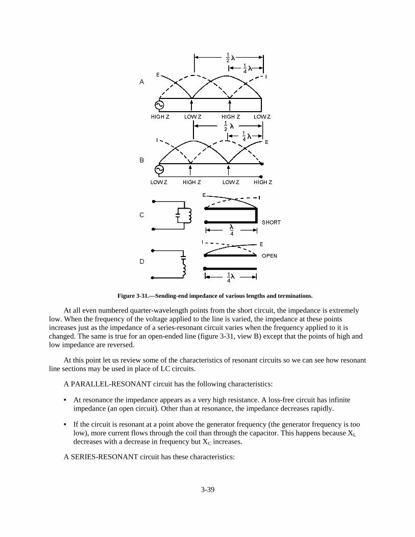
3-39
Figure 3-31.—Sending-end impedance of various lengths and terminations.
At all even numbered quarter-wavelength points from the short circuit, the impedance is extremelylow. When the frequency of the voltage applied to the line is varied, the impedance at these pointsincreases just as the impedance of a series-resonant circuit varies when the frequency applied to it ischanged. The same is true for an open-ended line (figure 3-31, view B) except that the points of high andlow impedance are reversed.
At this point let us review some of the characteristics of resonant circuits so we can see how resonantline sections may be used in place of LC circuits.
A PARALLEL-RESONANT circuit has the following characteristics:
• At resonance the impedance appears as a very high resistance. A loss-free circuit has infiniteimpedance (an open circuit). Other than at resonance, the impedance decreases rapidly.
• If the circuit is resonant at a point above the generator frequency (the generator frequency is toolow), more current flows through the coil than through the capacitor. This happens because XL
decreases with a decrease in frequency but XC increases.
A SERIES-RESONANT circuit has these characteristics:
3-40
• At resonance the impedance appears as a very low resistance. A loss-free circuit has zeroimpedance (a short circuit). Other than at resonance the impedance increases rapidly.
• If the circuit is resonant at a point above the generator frequency (the generator frequency istoo low), then XC is larger than XL and the circuit acts capacitively.
• If the circuit is resonant at a point below the generator frequency (the generator frequency istoo high), then XL is larger than XC and the circuit acts inductively.
Since the impedance a generator sees at the quarter-wave point in a shorted line is that of a parallel-resonant circuit, a shorted quarter-wave- length of line may be used as a parallel-resonant circuit (figure3-31, view C). An open quarter-wavelength of line may be used as a series-resonant circuit (view D). TheQ of such a resonant line is much greater than can be obtained with lumped capacitance and inductance.
Impedance for Various Lengths of Open Lines
In figure 3-32, the impedance (Z) the generator sees for various lengths of line is shown at the top.The curves above the letters of various heights show the relative value of the impedances presented to thegenerator for the various line lengths. The circuit symbols indicate the equivalent electrical circuits for thetransmission lines at each particular length. The standing waves of voltage and current are shown on eachlength of line.
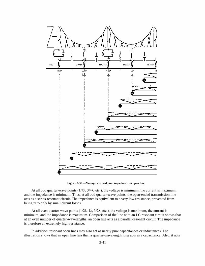
3-41
Figure 3-32.—Voltage, current, and impedance on open line.
$W�DOO�RGG�TXDUWHU�ZDYH�SRLQWV����� ����� ��HWF����WKH�YROWDJH�LV�PLQLPXP��WKH�FXUUHQW�LV�PD[LPXP�and the impedance is minimum. Thus, at all odd quarter-wave points, the open-ended transmission lineacts as a series-resonant circuit. The impedance is equivalent to a very low resistance, prevented frombeing zero only by small circuit losses.
$W�DOO�HYHQ�TXDUWHU�ZDYH�SRLQWV����� ��� ����� ��HWF����WKH�YROWDJH�LV�PD[LPXP��WKH�FXUUHQW�LVminimum, and the impedance is maximum. Comparison of the line with an LC resonant circuit shows thatat an even number of quarter-wavelengths, an open line acts as a parallel-resonant circuit. The impedanceis therefore an extremely high resistance.
In addition, resonant open lines may also act as nearly pure capacitances or inductances. Theillustration shows that an open line less than a quarter-wavelength long acts as a capacitance. Also, it acts
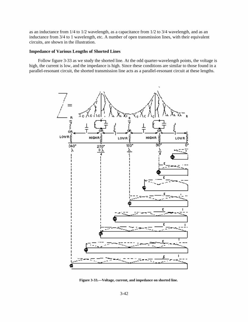
3-42
as an inductance from 1/4 to 1/2 wavelength, as a capacitance from 1/2 to 3/4 wavelength, and as aninductance from 3/4 to 1 wavelength, etc. A number of open transmission lines, with their equivalentcircuits, are shown in the illustration.
Impedance of Various Lengths of Shorted Lines
Follow figure 3-33 as we study the shorted line. At the odd quarter-wavelength points, the voltage ishigh, the current is low, and the impedance is high. Since these conditions are similar to those found in aparallel-resonant circuit, the shorted transmission line acts as a parallel-resonant circuit at these lengths.
Figure 3-33.—Voltage, current, and impedance on shorted line.
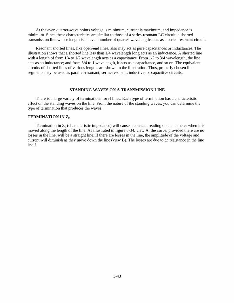
3-43
At the even quarter-wave points voltage is minimum, current is maximum, and impedance isminimum. Since these characteristics are similar to those of a series-resonant LC circuit, a shortedtransmission line whose length is an even number of quarter-wavelengths acts as a series-resonant circuit.
Resonant shorted lines, like open-end lines, also may act as pure capacitances or inductances. Theillustration shows that a shorted line less than 1/4 wavelength long acts as an inductance. A shorted linewith a length of from 1/4 to 1/2 wavelength acts as a capacitance. From 1/2 to 3/4 wavelength, the lineacts as an inductance; and from 3/4 to 1 wavelength, it acts as a capacitance, and so on. The equivalentcircuits of shorted lines of various lengths are shown in the illustration. Thus, properly chosen linesegments may be used as parallel-resonant, series-resonant, inductive, or capacitive circuits.
STANDING WAVES ON A TRANSMISSION LINE
There is a large variety of terminations for rf lines. Each type of termination has a characteristiceffect on the standing waves on the line. From the nature of the standing waves, you can determine thetype of termination that produces the waves.
TERMINATION IN Z0
Termination in Z0 (characteristic impedance) will cause a constant reading on an ac meter when it ismoved along the length of the line. As illustrated in figure 3-34, view A, the curve, provided there are nolosses in the line, will be a straight line. If there are losses in the line, the amplitude of the voltage andcurrent will diminish as they move down the line (view B). The losses are due to dc resistance in the lineitself.
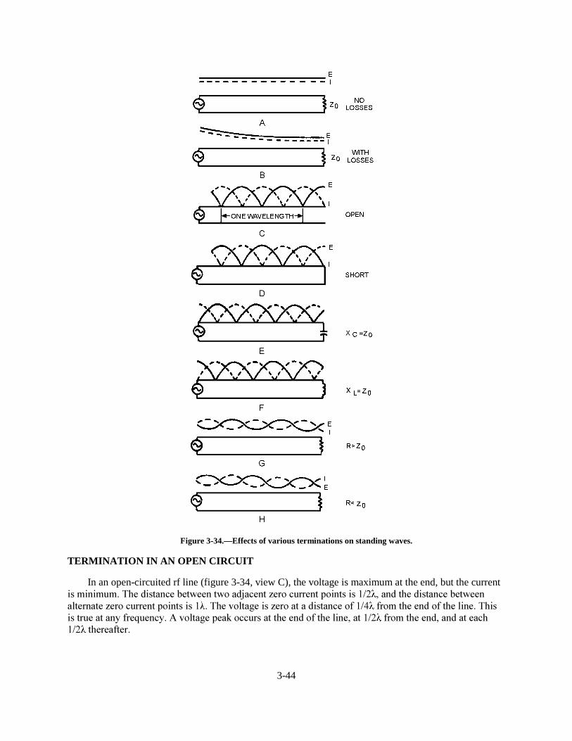
3-44
Figure 3-34.—Effects of various terminations on standing waves.
TERMINATION IN AN OPEN CIRCUIT
In an open-circuited rf line (figure 3-34, view C), the voltage is maximum at the end, but the currentLV�PLQLPXP��7KH�GLVWDQFH�EHWZHHQ�WZR�DGMDFHQW�]HUR�FXUUHQW�SRLQWV�LV���� ��DQG�WKH�GLVWDQFH�EHWZHHQDOWHUQDWH�]HUR�FXUUHQW�SRLQWV�LV�� ��7KH�YROWDJH�LV�]HUR�DW�D�GLVWDQFH�RI���� �IURP�WKH�HQG�RI�WKH�OLQH��7KLVLV�WUXH�DW�DQ\�IUHTXHQF\��$�YROWDJH�SHDN�RFFXUV�DW�WKH�HQG�RI�WKH�OLQH��DW���� �IURP�WKH�HQG��DQG�DW�HDFK��� �WKHUHDIWHU�
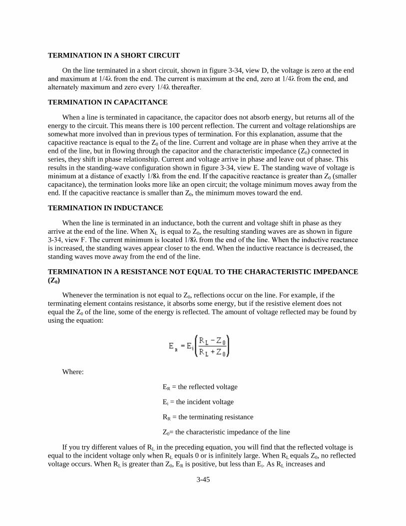
3-45
TERMINATION IN A SHORT CIRCUIT
On the line terminated in a short circuit, shown in figure 3-34, view D, the voltage is zero at the endDQG�PD[LPXP�DW���� �IURP�WKH�HQG��7KH�FXUUHQW�LV�PD[LPXP�DW�WKH�HQG��]HUR�DW���� �IURP�WKH�HQG��DQGDOWHUQDWHO\�PD[LPXP�DQG�]HUR�HYHU\���� �WKHUHDIWHU�
TERMINATION IN CAPACITANCE
When a line is terminated in capacitance, the capacitor does not absorb energy, but returns all of theenergy to the circuit. This means there is 100 percent reflection. The current and voltage relationships aresomewhat more involved than in previous types of termination. For this explanation, assume that thecapacitive reactance is equal to the Z0 of the line. Current and voltage are in phase when they arrive at theend of the line, but in flowing through the capacitor and the characteristic impedance (Z0) connected inseries, they shift in phase relationship. Current and voltage arrive in phase and leave out of phase. Thisresults in the standing-wave configuration shown in figure 3-34, view E. The standing wave of voltage isPLQLPXP�DW�D�GLVWDQFH�RI�H[DFWO\���� �IURP�WKH�HQG��,I�WKH�FDSDFLWLYH�UHDFWDQFH�LV�JUHDWHU�WKDQ�=0 (smallercapacitance), the termination looks more like an open circuit; the voltage minimum moves away from theend. If the capacitive reactance is smaller than Z0, the minimum moves toward the end.
TERMINATION IN INDUCTANCE
When the line is terminated in an inductance, both the current and voltage shift in phase as theyarrive at the end of the line. When XL is equal to Z0, the resulting standing waves are as shown in figure3�����YLHZ�)��7KH�FXUUHQW�PLQLPXP�LV�ORFDWHG���� �IURP�WKH�HQG�RI�WKH�OLQH��:KHQ�WKH�LQGXFWLYH�UHDFWDQFHis increased, the standing waves appear closer to the end. When the inductive reactance is decreased, thestanding waves move away from the end of the line.
TERMINATION IN A RESISTANCE NOT EQUAL TO THE CHARACTERISTIC IMPEDANCE(Z0)
Whenever the termination is not equal to Z0, reflections occur on the line. For example, if theterminating element contains resistance, it absorbs some energy, but if the resistive element does notequal the Z0 of the line, some of the energy is reflected. The amount of voltage reflected may be found byusing the equation:
Where:
ER = the reflected voltage
Ei = the incident voltage
RR = the terminating resistance
Z0= the characteristic impedance of the line
If you try different values of RL in the preceding equation, you will find that the reflected voltage isequal to the incident voltage only when RL equals 0 or is infinitely large. When RL equals Z0, no reflectedvoltage occurs. When RL is greater than Z0, ER is positive, but less than Ei. As RL increases and
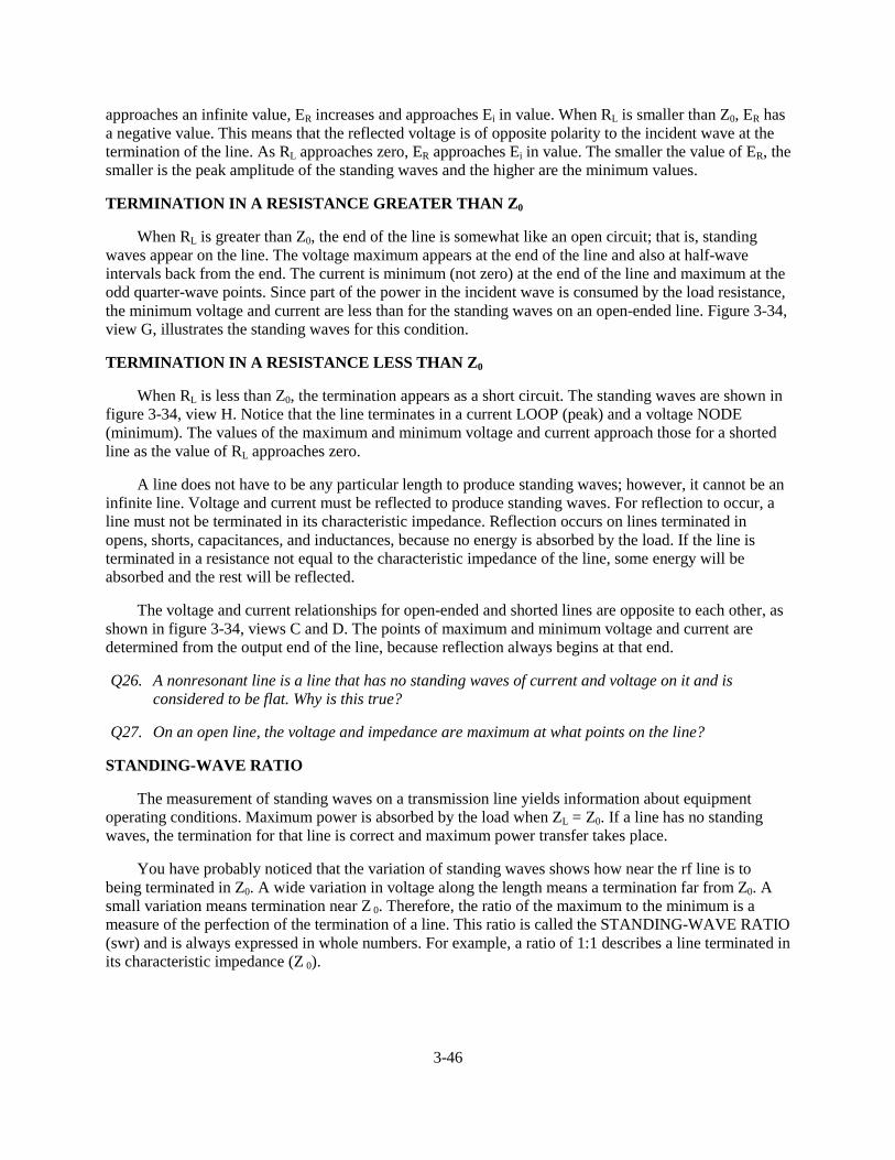
3-46
approaches an infinite value, ER increases and approaches Ei in value. When RL is smaller than Z0, ER hasa negative value. This means that the reflected voltage is of opposite polarity to the incident wave at thetermination of the line. As RL approaches zero, ER approaches Ei in value. The smaller the value of ER, thesmaller is the peak amplitude of the standing waves and the higher are the minimum values.
TERMINATION IN A RESISTANCE GREATER THAN Z0
When RL is greater than Z0, the end of the line is somewhat like an open circuit; that is, standingwaves appear on the line. The voltage maximum appears at the end of the line and also at half-waveintervals back from the end. The current is minimum (not zero) at the end of the line and maximum at theodd quarter-wave points. Since part of the power in the incident wave is consumed by the load resistance,the minimum voltage and current are less than for the standing waves on an open-ended line. Figure 3-34,view G, illustrates the standing waves for this condition.
TERMINATION IN A RESISTANCE LESS THAN Z0
When RL is less than Z0, the termination appears as a short circuit. The standing waves are shown infigure 3-34, view H. Notice that the line terminates in a current LOOP (peak) and a voltage NODE(minimum). The values of the maximum and minimum voltage and current approach those for a shortedline as the value of RL approaches zero.
A line does not have to be any particular length to produce standing waves; however, it cannot be aninfinite line. Voltage and current must be reflected to produce standing waves. For reflection to occur, aline must not be terminated in its characteristic impedance. Reflection occurs on lines terminated inopens, shorts, capacitances, and inductances, because no energy is absorbed by the load. If the line isterminated in a resistance not equal to the characteristic impedance of the line, some energy will beabsorbed and the rest will be reflected.
The voltage and current relationships for open-ended and shorted lines are opposite to each other, asshown in figure 3-34, views C and D. The points of maximum and minimum voltage and current aredetermined from the output end of the line, because reflection always begins at that end.
Q26. A nonresonant line is a line that has no standing waves of current and voltage on it and isconsidered to be flat. Why is this true?
Q27. On an open line, the voltage and impedance are maximum at what points on the line?
STANDING-WAVE RATIO
The measurement of standing waves on a transmission line yields information about equipmentoperating conditions. Maximum power is absorbed by the load when ZL = Z0. If a line has no standingwaves, the termination for that line is correct and maximum power transfer takes place.
You have probably noticed that the variation of standing waves shows how near the rf line is tobeing terminated in Z0. A wide variation in voltage along the length means a termination far from Z0. Asmall variation means termination near Z 0. Therefore, the ratio of the maximum to the minimum is ameasure of the perfection of the termination of a line. This ratio is called the STANDING-WAVE RATIO(swr) and is always expressed in whole numbers. For example, a ratio of 1:1 describes a line terminated inits characteristic impedance (Z 0).
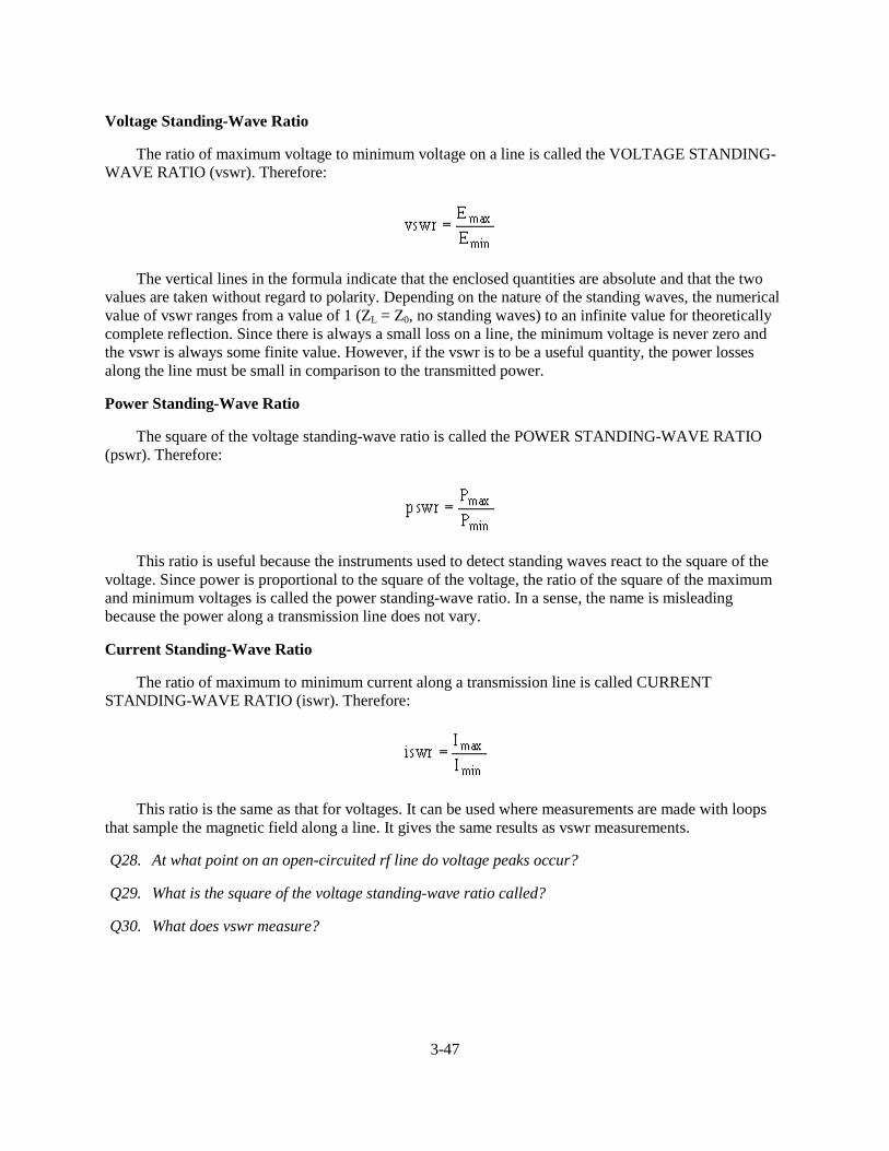
3-47
Voltage Standing-Wave Ratio
The ratio of maximum voltage to minimum voltage on a line is called the VOLTAGE STANDING-WAVE RATIO (vswr). Therefore:
The vertical lines in the formula indicate that the enclosed quantities are absolute and that the twovalues are taken without regard to polarity. Depending on the nature of the standing waves, the numericalvalue of vswr ranges from a value of 1 (ZL = Z0, no standing waves) to an infinite value for theoreticallycomplete reflection. Since there is always a small loss on a line, the minimum voltage is never zero andthe vswr is always some finite value. However, if the vswr is to be a useful quantity, the power lossesalong the line must be small in comparison to the transmitted power.
Power Standing-Wave Ratio
The square of the voltage standing-wave ratio is called the POWER STANDING-WAVE RATIO(pswr). Therefore:
This ratio is useful because the instruments used to detect standing waves react to the square of thevoltage. Since power is proportional to the square of the voltage, the ratio of the square of the maximumand minimum voltages is called the power standing-wave ratio. In a sense, the name is misleadingbecause the power along a transmission line does not vary.
Current Standing-Wave Ratio
The ratio of maximum to minimum current along a transmission line is called CURRENTSTANDING-WAVE RATIO (iswr). Therefore:
This ratio is the same as that for voltages. It can be used where measurements are made with loopsthat sample the magnetic field along a line. It gives the same results as vswr measurements.
Q28. At what point on an open-circuited rf line do voltage peaks occur?
Q29. What is the square of the voltage standing-wave ratio called?
Q30. What does vswr measure?
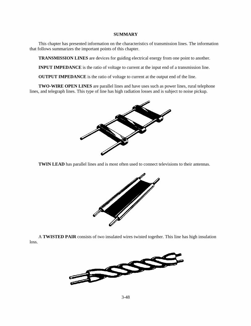
3-48
SUMMARY
This chapter has presented information on the characteristics of transmission lines. The informationthat follows summarizes the important points of this chapter.
TRANSMISSION LINES are devices for guiding electrical energy from one point to another.
INPUT IMPEDANCE is the ratio of voltage to current at the input end of a transmission line.
OUTPUT IMPEDANCE is the ratio of voltage to current at the output end of the line.
TWO-WIRE OPEN LINES are parallel lines and have uses such as power lines, rural telephonelines, and telegraph lines. This type of line has high radiation losses and is subject to noise pickup.
TWIN LEAD has parallel lines and is most often used to connect televisions to their antennas.
A TWISTED PAIR consists of two insulated wires twisted together. This line has high insulationloss.
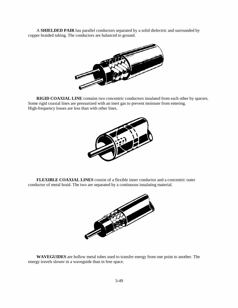
3-49
A SHIELDED PAIR has parallel conductors separated by a solid dielectric and surrounded bycopper braided tubing. The conductors are balanced to ground.
RIGID COAXIAL LINE contains two concentric conductors insulated from each other by spacers.Some rigid coaxial lines are pressurized with an inert gas to prevent moisture from entering.High-frequency losses are less than with other lines.
FLEXIBLE COAXIAL LINES consist of a flexible inner conductor and a concentric outerconductor of metal braid. The two are separated by a continuous insulating material.
WAVEGUIDES are hollow metal tubes used to transfer energy from one point to another. Theenergy travels slower in a waveguide than in free space.
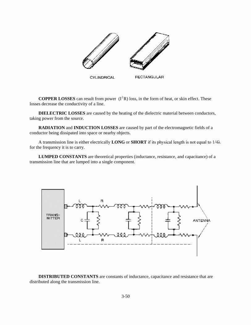
3-50
COPPER LOSSES can result from power (I 2R) loss, in the form of heat, or skin effect. Theselosses decrease the conductivity of a line.
DIELECTRIC LOSSES are caused by the heating of the dielectric material between conductors,taking power from the source.
RADIATION and INDUCTION LOSSES are caused by part of the electromagnetic fields of aconductor being dissipated into space or nearby objects.
A transmission line is either electrically LONG or SHORT�LI�LWV�SK\VLFDO�OHQJWK�LV�QRW�HTXDO�WR����for the frequency it is to carry.
LUMPED CONSTANTS are theoretical properties (inductance, resistance, and capacitance) of atransmission line that are lumped into a single component.
DISTRIBUTED CONSTANTS are constants of inductance, capacitance and resistance that aredistributed along the transmission line.
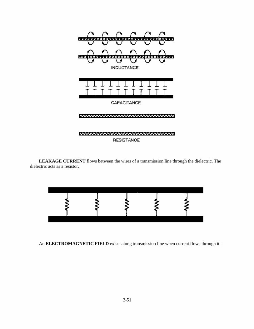
3-51
LEAKAGE CURRENT flows between the wires of a transmission line through the dielectric. Thedielectric acts as a resistor.
An ELECTROMAGNETIC FIELD exists along transmission line when current flows through it.
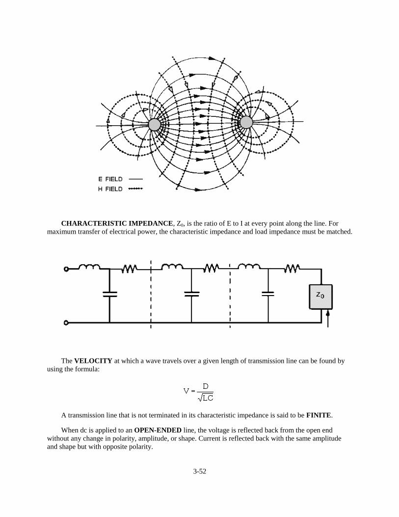
3-52
CHARACTERISTIC IMPEDANCE, Z0, is the ratio of E to I at every point along the line. Formaximum transfer of electrical power, the characteristic impedance and load impedance must be matched.
The VELOCITY at which a wave travels over a given length of transmission line can be found byusing the formula:
A transmission line that is not terminated in its characteristic impedance is said to be FINITE.
When dc is applied to an OPEN-ENDED line, the voltage is reflected back from the open endwithout any change in polarity, amplitude, or shape. Current is reflected back with the same amplitudeand shape but with opposite polarity.
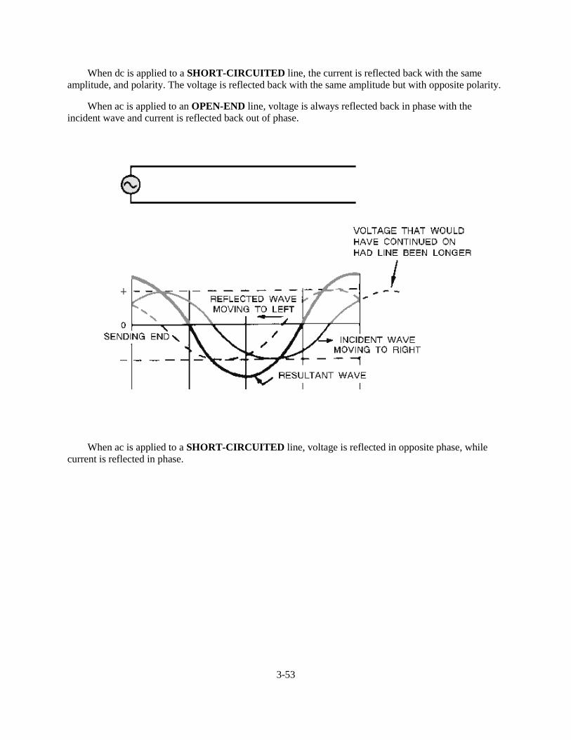
3-53
When dc is applied to a SHORT-CIRCUITED line, the current is reflected back with the sameamplitude, and polarity. The voltage is reflected back with the same amplitude but with opposite polarity.
When ac is applied to an OPEN-END line, voltage is always reflected back in phase with theincident wave and current is reflected back out of phase.
When ac is applied to a SHORT-CIRCUITED line, voltage is reflected in opposite phase, whilecurrent is reflected in phase.
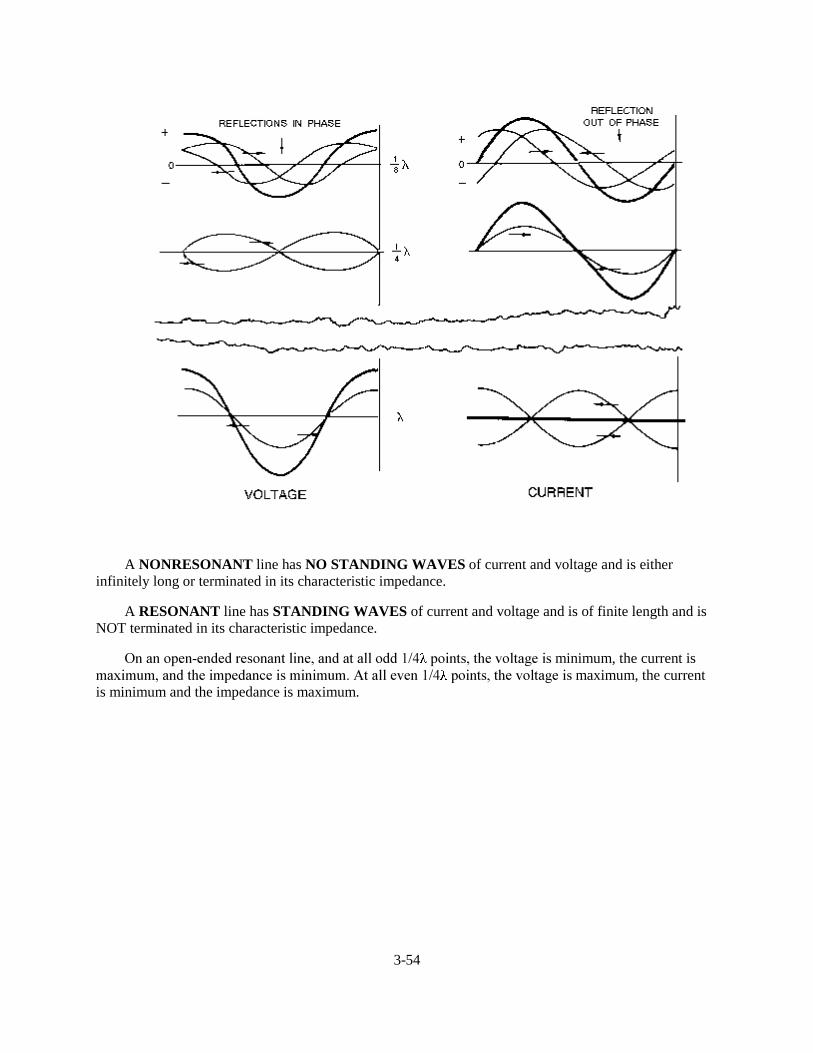
3-54
A NONRESONANT line has NO STANDING WAVES of current and voltage and is eitherinfinitely long or terminated in its characteristic impedance.
A RESONANT line has STANDING WAVES of current and voltage and is of finite length and isNOT terminated in its characteristic impedance.
2Q�DQ�RSHQ�HQGHG�UHVRQDQW�OLQH��DQG�DW�DOO�RGG���� �SRLQWV��WKH�YROWDJH�LV�minimum, the current isPD[LPXP��DQG�WKH�LPSHGDQFH�LV�PLQLPXP��$W�DOO�HYHQ���� �SRLQWV��WKH�YROWDJH�LV�maximum, the currentis minimum and the impedance is maximum.
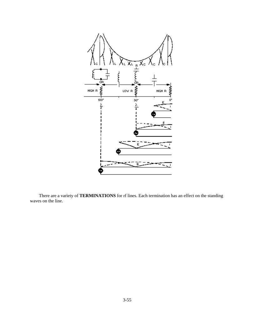
3-55
There are a variety of TERMINATIONS for rf lines. Each termination has an effect on the standingwaves on the line.
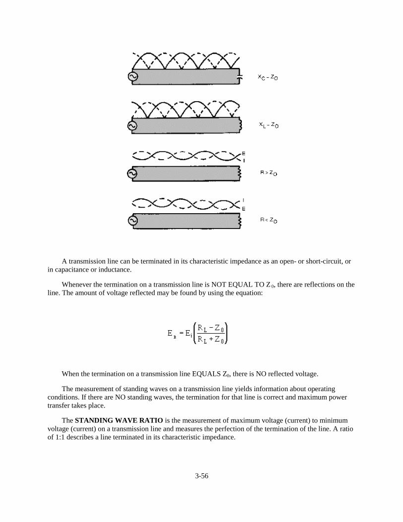
3-56
A transmission line can be terminated in its characteristic impedance as an open- or short-circuit, orin capacitance or inductance.
Whenever the termination on a transmission line is NOT EQUAL TO Z 0, there are reflections on theline. The amount of voltage reflected may be found by using the equation:
When the termination on a transmission line EQUALS Z0, there is NO reflected voltage.
The measurement of standing waves on a transmission line yields information about operatingconditions. If there are NO standing waves, the termination for that line is correct and maximum powertransfer takes place.
The STANDING WAVE RATIO is the measurement of maximum voltage (current) to minimumvoltage (current) on a transmission line and measures the perfection of the termination of the line. A ratioof 1:1 describes a line terminated in its characteristic impedance.
3-57
ANSWERS TO QUESTIONS Q1. THROUGH Q30.
A1. Transmission line.
A2. Input end, generator end, transmitter end, sending end, and source.
A3. Output end, receiving end, load end and sink.
A4. Parallel two-wire, twisted pair, shielded pair, coaxial line and waveguide.
A5. Power lines, rural telephone lines, and telegraph lines.
A6. High radiation losses and noise pickup.
A7. Twin lead.
A8. The conductors are balanced to ground.
A9. Air coaxial (rigid) and solid coaxial (flexible).
A10. The ability to minimize radiation losses.
A11. Expensive to construct, must be kept dry, and high frequency losses limit the practical length ofthe line.
A12. Cylindrical and rectangular.
A13. Copper, dielectric, and radiation.
A14. Copper losses.
A15. Dielectric losses.
A16. � ����PHWHUV�
A17. (1) Type of line used, (2) dielectric in the line, and (3) length of line.
A18. Inductance is expressed in microhenrys per unit length, capacitance is expressed in picofarads perunit length, and resistance is expressed in ohms per unit length.
A19. The small amount of current that flows through the dielectric between two wires of a transmissionline and is expressed in micromhos per unit length.
A20. When the characteristic impedance of the transmission line and the load impedance are equal.
A21. Z0 and it is the ratio of E to I at every point along the line.
A22. Between 50 and 600 ohms.
A23. Incident waves from generator to load. Reflected waves from load back to generator.
A24. 2 and 6 have zero resultant wave and they indicate that the incident and reflected waves are 180degrees out of phase at all parts.
A25. One-fourth the distance from each end of the line.
3-58
A26. The load impedance of such a line is equal to Z0.
A27. (YHQ�TXDUWHU�ZDYH�SRLQWV����� ��� ����� ��HWF���
A28. At 1/2 wavelength from the end and at every 1/2 wavelength along the line.
A29. Power standing-wave ratio (pswr).
A30. The existence of voltage variations on a line.
4-1
CHAPTER 4
ANTENNAS
LEARNING OBJECTIVES
Upon completion of this chapter you will be able to:
1. State the basic principles of antenna radiation and list the parts of an antenna.
2. Explain current and voltage distribution on an antenna.
3. Describe how electromagnetic energy is radiated from an antenna.
4. Explain polarization, gain, and radiation resistance characteristics of an antenna.
5. Describe the theory of operation of half- wave and quarter-wave antennas.
6. List the various array antennas.
7. Describe the directional array antennas presented and explain the basic operation of each.
8. Identify various special antennas presented, such as long-wire, V, rhombic, turnstile, ground-plane, and corner-reflector; describe the operation of each.
9. List safety precautions when working aloft and around antennas.
INTRODUCTION
If you had been around in the early days of electronics, you would have considered an ANTENNA (AERIAL) to be little more than a piece of wire strung between two trees or upright poles. In those days, technicians assumed that longer antennas automatically provided better reception than shorter antennas. They also believed that a mysterious MEDIUM filled all space, and that an antenna used this medium to send and receive its energy. These two assumptions have since been discarded. Modern antennas have evolved to the point that highly directional, specially designed antennas are used to relay worldwide communications in space through the use of satellites and Earth station antennas (fig. 4-1). Present transmission theories are based on the assumption that space itself is the only medium necessary to propagate (transmit) radio energy.
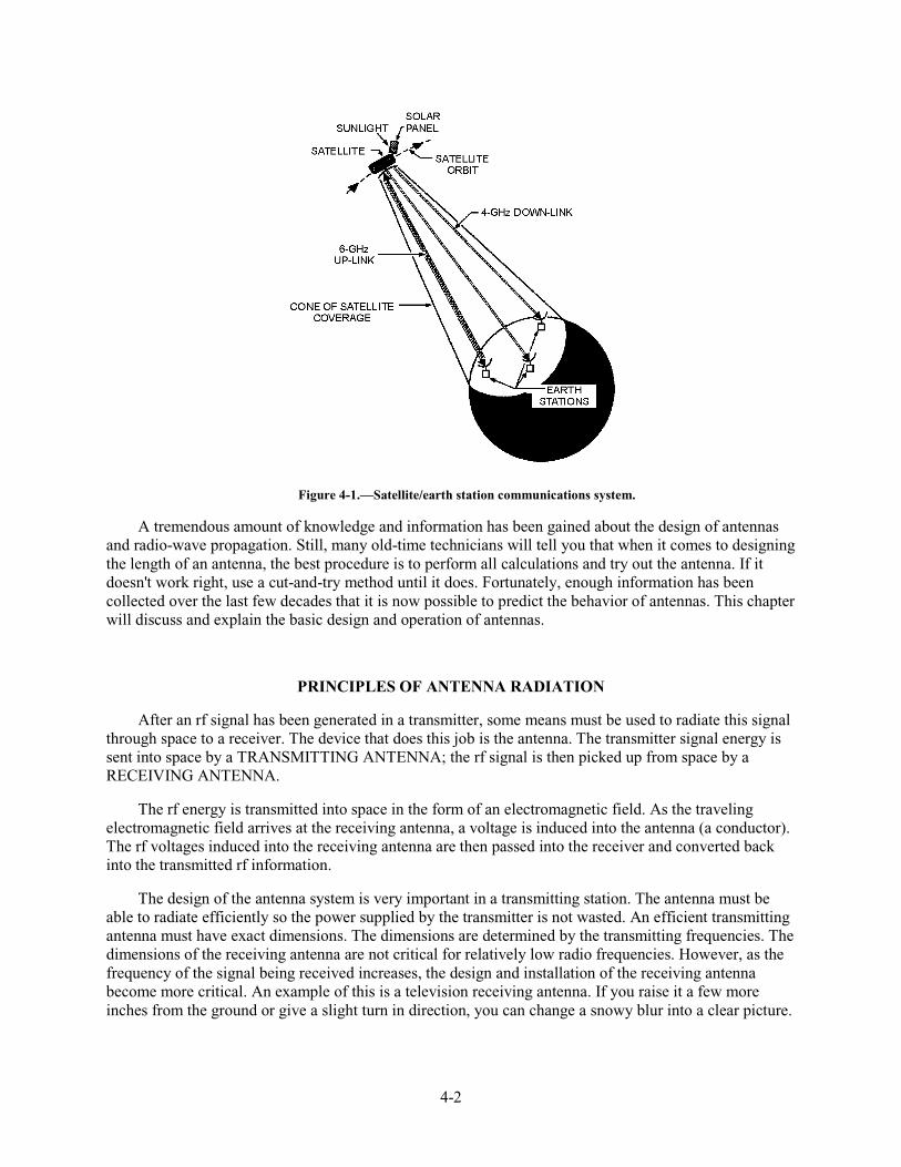
4-2
Figure 4-1.—Satellite/earth station communications system.
A tremendous amount of knowledge and information has been gained about the design of antennas and radio-wave propagation. Still, many old-time technicians will tell you that when it comes to designing the length of an antenna, the best procedure is to perform all calculations and try out the antenna. If it doesn't work right, use a cut-and-try method until it does. Fortunately, enough information has been collected over the last few decades that it is now possible to predict the behavior of antennas. This chapter will discuss and explain the basic design and operation of antennas.
PRINCIPLES OF ANTENNA RADIATION
After an rf signal has been generated in a transmitter, some means must be used to radiate this signal through space to a receiver. The device that does this job is the antenna. The transmitter signal energy is sent into space by a TRANSMITTING ANTENNA; the rf signal is then picked up from space by a RECEIVING ANTENNA.
The rf energy is transmitted into space in the form of an electromagnetic field. As the traveling electromagnetic field arrives at the receiving antenna, a voltage is induced into the antenna (a conductor). The rf voltages induced into the receiving antenna are then passed into the receiver and converted back into the transmitted rf information.
The design of the antenna system is very important in a transmitting station. The antenna must be able to radiate efficiently so the power supplied by the transmitter is not wasted. An efficient transmitting antenna must have exact dimensions. The dimensions are determined by the transmitting frequencies. The dimensions of the receiving antenna are not critical for relatively low radio frequencies. However, as the frequency of the signal being received increases, the design and installation of the receiving antenna become more critical. An example of this is a television receiving antenna. If you raise it a few more inches from the ground or give a slight turn in direction, you can change a snowy blur into a clear picture.

4-3
The conventional antenna is a conductor, or system of conductors, that radiates or intercepts electromagnetic wave energy. An ideal antenna has a definite length and a uniform diameter, and is completely isolated in space. However, this ideal antenna is not realistic. Many factors make the design of an antenna for a communications system a more complex problem than you would expect. These factors include the height of the radiator above the earth, the conductivity of the earth below it, and the shape and dimensions of the antenna. All of these factors affect the radiated-field pattern of the antenna in space. Another problem in antenna design is that the radiation pattern of the antenna must be directed between certain angles in a horizontal or vertical plane, or both.
Most practical transmitting antennas are divided into two basic classifications, HERTZ (half-wave) ANTENNAS and MARCONI (quarter-wave) ANTENNAS. Hertz antennas are generally installed some distance above the ground and are positioned to radiate either vertically or horizontally. Marconi antennas operate with one end grounded and are mounted perpendicular to the Earth or to a surface acting as a ground. Hertz antennas are generally used for frequencies above 2 megahertz. Marconi antennas are used for frequencies below 2 megahertz and may be used at higher frequencies in certain applications.
A complete antenna system consists of three parts: (1) The COUPLING DEVICE, (2) the FEEDER, and (3) the ANTENNA, as shown in figure 4-2. The coupling device (coupling coil) connects the transmitter to the feeder. The feeder is a transmission line that carries energy to the antenna. The antenna radiates this energy into space.
Figure 4-2.—Typical antenna system.
The factors that determine the type, size, and shape of the antenna are (1) the frequency of operation of the transmitter, (2) the amount of power to be radiated, and (3) the general direction of the receiving set. Typical antennas are shown in figure 4-3.
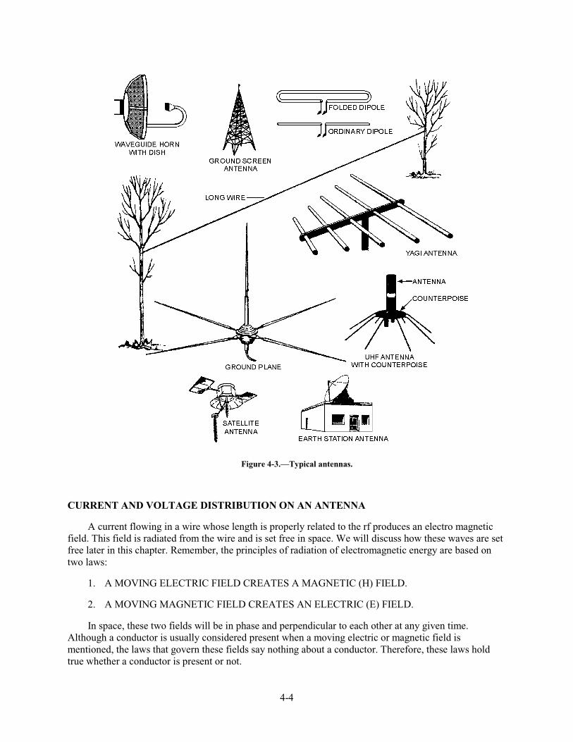
4-4
Figure 4-3.—Typical antennas.
CURRENT AND VOLTAGE DISTRIBUTION ON AN ANTENNA
A current flowing in a wire whose length is properly related to the rf produces an electro magnetic field. This field is radiated from the wire and is set free in space. We will discuss how these waves are set free later in this chapter. Remember, the principles of radiation of electromagnetic energy are based on two laws:
1. A MOVING ELECTRIC FIELD CREATES A MAGNETIC (H) FIELD.
2. A MOVING MAGNETIC FIELD CREATES AN ELECTRIC (E) FIELD.
In space, these two fields will be in phase and perpendicular to each other at any given time. Although a conductor is usually considered present when a moving electric or magnetic field is mentioned, the laws that govern these fields say nothing about a conductor. Therefore, these laws hold true whether a conductor is present or not.
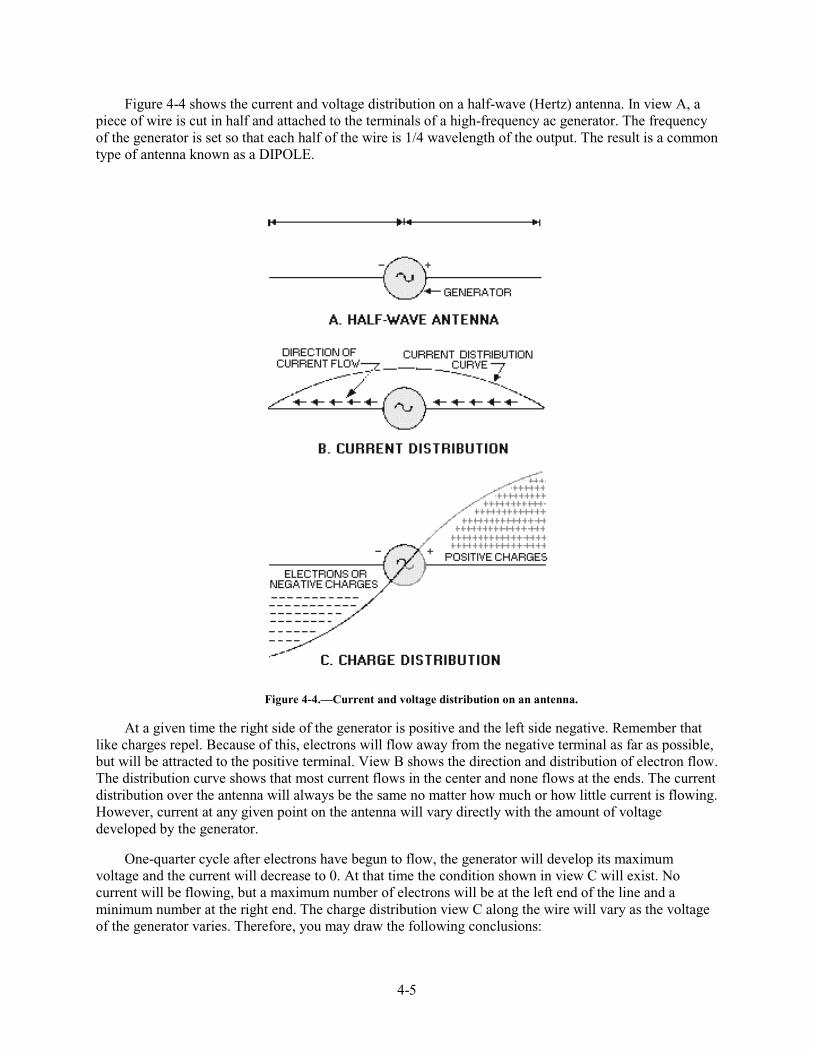
4-5
Figure 4-4 shows the current and voltage distribution on a half-wave (Hertz) antenna. In view A, a piece of wire is cut in half and attached to the terminals of a high-frequency ac generator. The frequency of the generator is set so that each half of the wire is 1/4 wavelength of the output. The result is a common type of antenna known as a DIPOLE.
Figure 4-4.—Current and voltage distribution on an antenna.
At a given time the right side of the generator is positive and the left side negative. Remember that like charges repel. Because of this, electrons will flow away from the negative terminal as far as possible, but will be attracted to the positive terminal. View B shows the direction and distribution of electron flow. The distribution curve shows that most current flows in the center and none flows at the ends. The current distribution over the antenna will always be the same no matter how much or how little current is flowing. However, current at any given point on the antenna will vary directly with the amount of voltage developed by the generator.
One-quarter cycle after electrons have begun to flow, the generator will develop its maximum voltage and the current will decrease to 0. At that time the condition shown in view C will exist. No current will be flowing, but a maximum number of electrons will be at the left end of the line and a minimum number at the right end. The charge distribution view C along the wire will vary as the voltage of the generator varies. Therefore, you may draw the following conclusions:
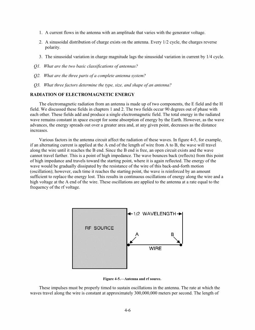
4-6
1. A current flows in the antenna with an amplitude that varies with the generator voltage.
2. A sinusoidal distribution of charge exists on the antenna. Every 1/2 cycle, the charges reverse polarity.
3. The sinusoidal variation in charge magnitude lags the sinusoidal variation in current by 1/4 cycle.
Q1. What are the two basic classifications of antennas?
Q2. What are the three parts of a complete antenna system?
Q3. What three factors determine the type, size, and shape of an antenna?
RADIATION OF ELECTROMAGNETIC ENERGY
The electromagnetic radiation from an antenna is made up of two components, the E field and the H field. We discussed these fields in chapters 1 and 2. The two fields occur 90 degrees out of phase with each other. These fields add and produce a single electromagnetic field. The total energy in the radiated wave remains constant in space except for some absorption of energy by the Earth. However, as the wave advances, the energy spreads out over a greater area and, at any given point, decreases as the distance increases.
Various factors in the antenna circuit affect the radiation of these waves. In figure 4-5, for example, if an alternating current is applied at the A end of the length of wire from A to B, the wave will travel along the wire until it reaches the B end. Since the B end is free, an open circuit exists and the wave cannot travel farther. This is a point of high impedance. The wave bounces back (reflects) from this point of high impedance and travels toward the starting point, where it is again reflected. The energy of the wave would be gradually dissipated by the resistance of the wire of this back-and-forth motion (oscillation); however, each time it reaches the starting point, the wave is reinforced by an amount sufficient to replace the energy lost. This results in continuous oscillations of energy along the wire and a high voltage at the A end of the wire. These oscillations are applied to the antenna at a rate equal to the frequency of the rf voltage.
Figure 4-5.—Antenna and rf source.
These impulses must be properly timed to sustain oscillations in the antenna. The rate at which the waves travel along the wire is constant at approximately 300,000,000 meters per second. The length of
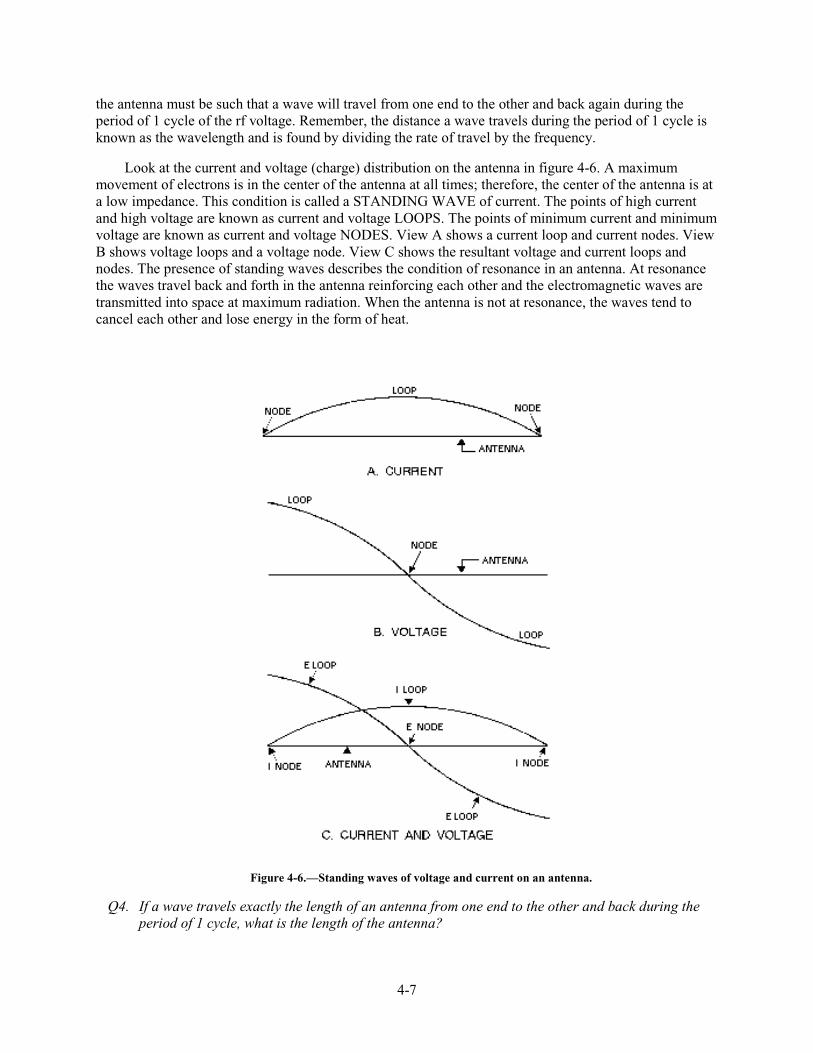
4-7
the antenna must be such that a wave will travel from one end to the other and back again during the period of 1 cycle of the rf voltage. Remember, the distance a wave travels during the period of 1 cycle is known as the wavelength and is found by dividing the rate of travel by the frequency.
Look at the current and voltage (charge) distribution on the antenna in figure 4-6. A maximum movement of electrons is in the center of the antenna at all times; therefore, the center of the antenna is at a low impedance. This condition is called a STANDING WAVE of current. The points of high current and high voltage are known as current and voltage LOOPS. The points of minimum current and minimum voltage are known as current and voltage NODES. View A shows a current loop and current nodes. View B shows voltage loops and a voltage node. View C shows the resultant voltage and current loops and nodes. The presence of standing waves describes the condition of resonance in an antenna. At resonance the waves travel back and forth in the antenna reinforcing each other and the electromagnetic waves are transmitted into space at maximum radiation. When the antenna is not at resonance, the waves tend to cancel each other and lose energy in the form of heat.
Figure 4-6.—Standing waves of voltage and current on an antenna.
Q4. If a wave travels exactly the length of an antenna from one end to the other and back during the period of 1 cycle, what is the length of the antenna?
4-8
Q5. What is the term used to identify the points of high current and high voltage on an antenna?
Q6. What is the term used to identify the points of minimum current and minimum voltage on an antenna?
ANTENNA CHARACTERISTICS
You can define an antenna as a conductor or group of conductors used either for radiating electromagnetic energy into space or for collecting it from space. Electrical energy from the transmitter is converted into electromagnetic energy by the antenna and radiated into space. On the receiving end, electromagnetic energy is converted into electrical energy by the antenna and is fed into the receiver.
Fortunately, separate antennas seldom are required for both transmitting and receiving rf energy. Any antenna can transfer energy from space to its input receiver with the same efficiency that it transfers energy from the transmitter into space. Of course, this is assuming that the same frequency is used in both cases. This property of interchangeability of the same antenna for transmitting and receiving is known as antenna RECIPROCITY. Antenna reciprocity is possible because antenna characteristics are essentially the same for sending and receiving electromagnetic energy.
RECIPROCITY OF ANTENNAS
In general, the various properties of an antenna apply equally, regardless of whether you use the antenna for transmitting or receiving. The more efficient a certain antenna is for transmitting, the more efficient it will be for receiving on the same frequency. Likewise, the directive properties of a given antenna also will be the same whether it is used for transmitting or receiving.
Assume, for example, that a certain antenna used with a transmitter radiates a maximum amount of energy at right angles to the axis of the antenna, as shown in figure 4-7, view A. Note the minimum amount of radiation along the axis of the antenna. Now, if this same antenna were used as a receiving antenna, as shown in view B, it would receive best in the same directions in which it produced maximum radiation; that is, at right angles to the axis of the antenna.
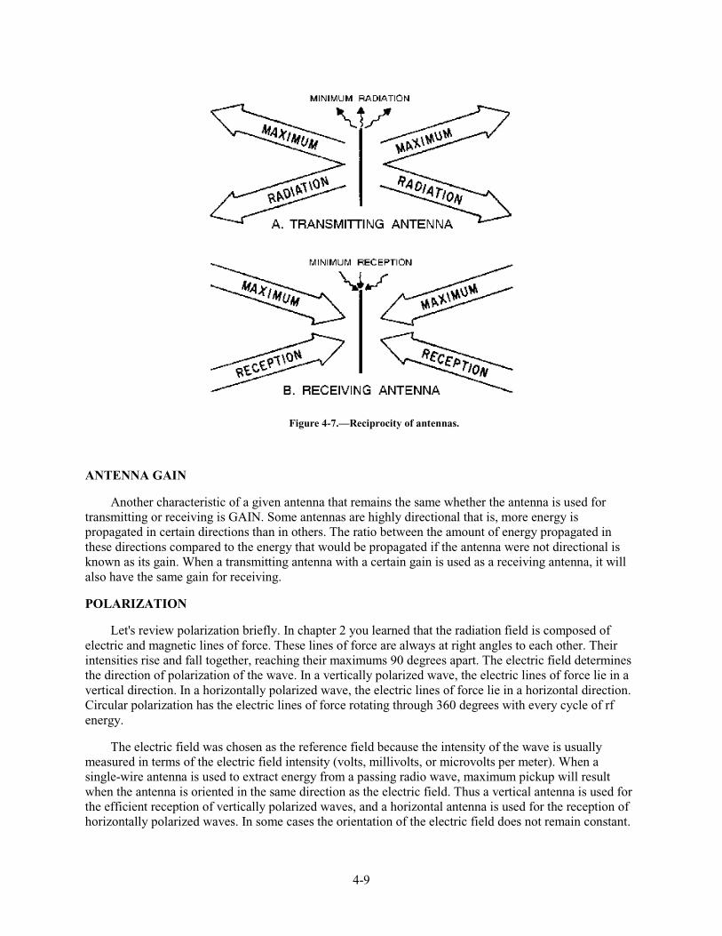
4-9
Figure 4-7.—Reciprocity of antennas.
ANTENNA GAIN
Another characteristic of a given antenna that remains the same whether the antenna is used for transmitting or receiving is GAIN. Some antennas are highly directional that is, more energy is propagated in certain directions than in others. The ratio between the amount of energy propagated in these directions compared to the energy that would be propagated if the antenna were not directional is known as its gain. When a transmitting antenna with a certain gain is used as a receiving antenna, it will also have the same gain for receiving.
POLARIZATION
Let's review polarization briefly. In chapter 2 you learned that the radiation field is composed of electric and magnetic lines of force. These lines of force are always at right angles to each other. Their intensities rise and fall together, reaching their maximums 90 degrees apart. The electric field determines the direction of polarization of the wave. In a vertically polarized wave, the electric lines of force lie in a vertical direction. In a horizontally polarized wave, the electric lines of force lie in a horizontal direction. Circular polarization has the electric lines of force rotating through 360 degrees with every cycle of rf energy.
The electric field was chosen as the reference field because the intensity of the wave is usually measured in terms of the electric field intensity (volts, millivolts, or microvolts per meter). When a single-wire antenna is used to extract energy from a passing radio wave, maximum pickup will result when the antenna is oriented in the same direction as the electric field. Thus a vertical antenna is used for the efficient reception of vertically polarized waves, and a horizontal antenna is used for the reception of horizontally polarized waves. In some cases the orientation of the electric field does not remain constant.
4-10
Instead, the field rotates as the wave travels through space. Under these conditions both horizontal and vertical components of the field exist and the wave is said to have an elliptical polarization.
Q7. The various properties of a transmitting antenna can apply equally to the same antenna when it is used as a receiving antenna. What term is used for this property?
Q8. The direction of what field is used to designate the polarization of a wave?
Q9. If a wave's electric lines of force rotate through 360 degrees with every cycle of rf energy, what is the polarization of this wave?
Polarization Requirements for Various Frequencies
Ground-wave transmission is widely used at medium and low frequencies. Horizontal polarization cannot be used at these frequencies because the electric lines of force are parallel to and touch the earth. Since the earth acts as a fairly good conductor at low frequencies, it would short out the horizontal electric lines of force and prevent the radio wave from traveling very far. Vertical electric lines of force, on the other hand, are bothered very little by the earth. Therefore vertical polarization is used for ground-wave transmission, allowing the radio wave to travel a considerable distance along the ground surface with minimum attenuation.
Sky-wave transmission is used at high frequencies. Either horizontal or vertical polarization can be used with sky-wave transmission because the sky wave arrives at the receiving antenna elliptically polarized. This is the result of the wave traveling obliquely through the Earth's magnetic field and striking the ionosphere. The radio wave is given a twisting motion as it strikes the ionosphere. Its orientation continues to change because of the unstable nature of the ionosphere. The relative amplitudes and phase differences between the horizontal and vertical components of the received wave also change. Therefore, the transmitting and receiving antennas can be mounted either horizontally or vertically.
Although either horizontally or vertically polarized antennas can be used for high frequencies, horizontally polarized antennas have certain advantages and are therefore preferred. One advantage is that vertically polarized interference signals, such as those produced by automobile ignition systems and electrical appliances, are minimized by horizontal polarization. Also, less absorption of radiated energy by buildings or wiring occurs when these antennas are used. Another advantage is that support structures for these antennas are of more convenient size than those for vertically polarized antennas.
For frequencies in the vhf or uhf range, either horizontal or vertical polarization is satisfactory. These radio waves travel directly from the transmitting antenna to the receiving antenna without entering the ionosphere. The original polarization produced at the transmitting antenna is maintained throughout the entire travel of the wave to the receiver. Therefore, if a horizontally polarized antenna is used for transmitting, a horizontally polarized antenna must be used for receiving. The requirements would be the same for a vertical transmitting and receiving antenna system.
For satellite communications, parallel frequencies can be used without interference by using polarized radiation. The system setup is shown in figure 4-8. One pair of satellite antennas is vertically polarized and another pair is horizontally polarized. Either vertically or horizontally polarized transmissions are received by the respective antenna and retransmitted in the same polarization. For example, transmissions may be made in the 3.7 to 3.74 GHz range on the vertical polarization path and in the 3.72 to 3.76 GHz range on the horizontal polarization path without adjacent frequency (co-channel) interference.
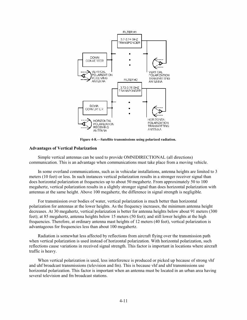
4-11
Figure 4-8.—Satellite transmissions using polarized radiation.
Advantages of Vertical Polarization
Simple vertical antennas can be used to provide OMNIDIRECTIONAL (all directions) communication. This is an advantage when communications must take place from a moving vehicle.
In some overland communications, such as in vehicular installations, antenna heights are limited to 3 meters (10 feet) or less. In such instances vertical polarization results in a stronger receiver signal than does horizontal polarization at frequencies up to about 50 megahertz. From approximately 50 to 100 megahertz, vertical polarization results in a slightly stronger signal than does horizontal polarization with antennas at the same height. Above 100 megahertz, the difference in signal strength is negligible.
For transmission over bodies of water, vertical polarization is much better than horizontal polarization for antennas at the lower heights. As the frequency increases, the minimum antenna height decreases. At 30 megahertz, vertical polarization is better for antenna heights below about 91 meters (300 feet); at 85 megahertz, antenna heights below 15 meters (50 feet); and still lower heights at the high frequencies. Therefore, at ordinary antenna mast heights of 12 meters (40 feet), vertical polarization is advantageous for frequencies less than about 100 megahertz.
Radiation is somewhat less affected by reflections from aircraft flying over the transmission path when vertical polarization is used instead of horizontal polarization. With horizontal polarization, such reflections cause variations in received signal strength. This factor is important in locations where aircraft traffic is heavy.
When vertical polarization is used, less interference is produced or picked up because of strong vhf and uhf broadcast transmissions (television and fm). This is because vhf and uhf transmissions use horizontal polarization. This factor is important when an antenna must be located in an urban area having several television and fm broadcast stations.
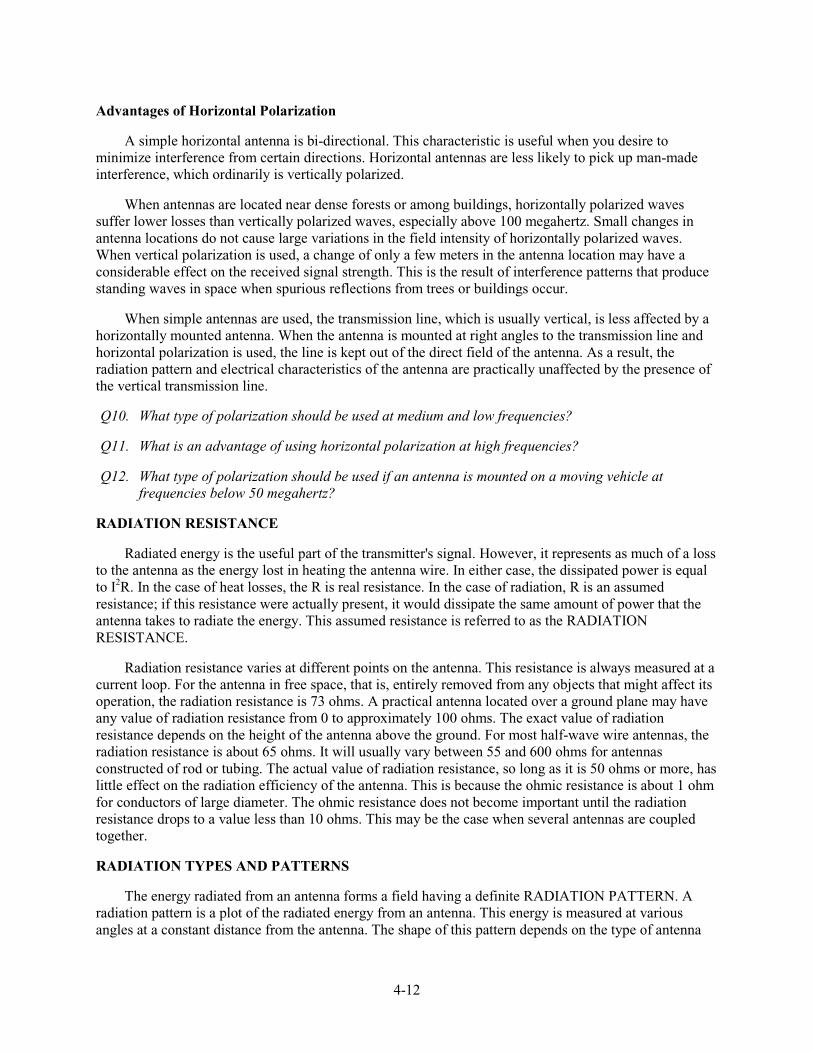
4-12
Advantages of Horizontal Polarization
A simple horizontal antenna is bi-directional. This characteristic is useful when you desire to minimize interference from certain directions. Horizontal antennas are less likely to pick up man-made interference, which ordinarily is vertically polarized.
When antennas are located near dense forests or among buildings, horizontally polarized waves suffer lower losses than vertically polarized waves, especially above 100 megahertz. Small changes in antenna locations do not cause large variations in the field intensity of horizontally polarized waves. When vertical polarization is used, a change of only a few meters in the antenna location may have a considerable effect on the received signal strength. This is the result of interference patterns that produce standing waves in space when spurious reflections from trees or buildings occur.
When simple antennas are used, the transmission line, which is usually vertical, is less affected by a horizontally mounted antenna. When the antenna is mounted at right angles to the transmission line and horizontal polarization is used, the line is kept out of the direct field of the antenna. As a result, the radiation pattern and electrical characteristics of the antenna are practically unaffected by the presence of the vertical transmission line.
Q10. What type of polarization should be used at medium and low frequencies?
Q11. What is an advantage of using horizontal polarization at high frequencies?
Q12. What type of polarization should be used if an antenna is mounted on a moving vehicle at frequencies below 50 megahertz?
RADIATION RESISTANCE
Radiated energy is the useful part of the transmitter's signal. However, it represents as much of a loss to the antenna as the energy lost in heating the antenna wire. In either case, the dissipated power is equal to I2R. In the case of heat losses, the R is real resistance. In the case of radiation, R is an assumed resistance; if this resistance were actually present, it would dissipate the same amount of power that the antenna takes to radiate the energy. This assumed resistance is referred to as the RADIATION RESISTANCE.
Radiation resistance varies at different points on the antenna. This resistance is always measured at a current loop. For the antenna in free space, that is, entirely removed from any objects that might affect its operation, the radiation resistance is 73 ohms. A practical antenna located over a ground plane may have any value of radiation resistance from 0 to approximately 100 ohms. The exact value of radiation resistance depends on the height of the antenna above the ground. For most half-wave wire antennas, the radiation resistance is about 65 ohms. It will usually vary between 55 and 600 ohms for antennas constructed of rod or tubing. The actual value of radiation resistance, so long as it is 50 ohms or more, has little effect on the radiation efficiency of the antenna. This is because the ohmic resistance is about 1 ohm for conductors of large diameter. The ohmic resistance does not become important until the radiation resistance drops to a value less than 10 ohms. This may be the case when several antennas are coupled together.
RADIATION TYPES AND PATTERNS
The energy radiated from an antenna forms a field having a definite RADIATION PATTERN. A radiation pattern is a plot of the radiated energy from an antenna. This energy is measured at various angles at a constant distance from the antenna. The shape of this pattern depends on the type of antenna
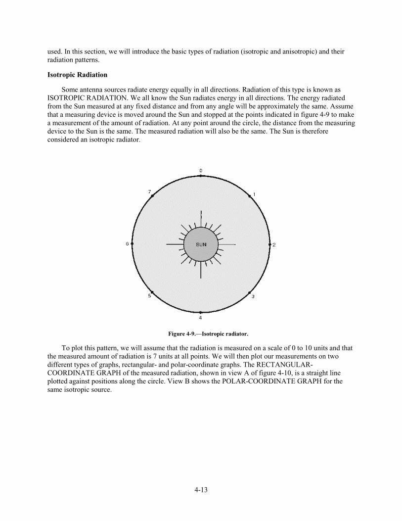
4-13
used. In this section, we will introduce the basic types of radiation (isotropic and anisotropic) and their radiation patterns.
Isotropic Radiation
Some antenna sources radiate energy equally in all directions. Radiation of this type is known as ISOTROPIC RADIATION. We all know the Sun radiates energy in all directions. The energy radiated from the Sun measured at any fixed distance and from any angle will be approximately the same. Assume that a measuring device is moved around the Sun and stopped at the points indicated in figure 4-9 to make a measurement of the amount of radiation. At any point around the circle, the distance from the measuring device to the Sun is the same. The measured radiation will also be the same. The Sun is therefore considered an isotropic radiator.
Figure 4-9.—Isotropic radiator.
To plot this pattern, we will assume that the radiation is measured on a scale of 0 to 10 units and that the measured amount of radiation is 7 units at all points. We will then plot our measurements on two different types of graphs, rectangular- and polar-coordinate graphs. The RECTANGULAR-COORDINATE GRAPH of the measured radiation, shown in view A of figure 4-10, is a straight line plotted against positions along the circle. View B shows the POLAR-COORDINATE GRAPH for the same isotropic source.
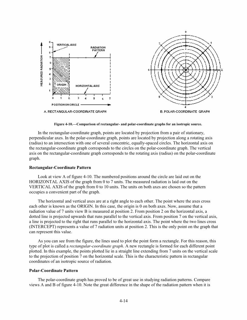
4-14
Figure 4-10.—Comparison of rectangular- and polar-coordinate graphs for an isotropic source.
In the rectangular-coordinate graph, points are located by projection from a pair of stationary, perpendicular axes. In the polar-coordinate graph, points are located by projection along a rotating axis (radius) to an intersection with one of several concentric, equally-spaced circles. The horizontal axis on the rectangular-coordinate graph corresponds to the circles on the polar-coordinate graph. The vertical axis on the rectangular-coordinate graph corresponds to the rotating axis (radius) on the polar-coordinate graph.
Rectangular-Coordinate Pattern
Look at view A of figure 4-10. The numbered positions around the circle are laid out on the HORIZONTAL AXIS of the graph from 0 to 7 units. The measured radiation is laid out on the VERTICAL AXIS of the graph from 0 to 10 units. The units on both axes are chosen so the pattern occupies a convenient part of the graph.
The horizontal and vertical axes are at a right angle to each other. The point where the axes cross each other is known as the ORIGIN. In this case, the origin is 0 on both axes. Now, assume that a radiation value of 7 units view B is measured at position 2. From position 2 on the horizontal axis, a dotted line is projected upwards that runs parallel to the vertical axis. From position 7 on the vertical axis, a line is projected to the right that runs parallel to the horizontal axis. The point where the two lines cross (INTERCEPT) represents a value of 7 radiation units at position 2. This is the only point on the graph that can represent this value.
As you can see from the figure, the lines used to plot the point form a rectangle. For this reason, this type of plot is called a rectangular-coordinate graph. A new rectangle is formed for each different point plotted. In this example, the points plotted lie in a straight line extending from 7 units on the vertical scale to the projection of position 7 on the horizontal scale. This is the characteristic pattern in rectangular coordinates of an isotropic source of radiation.
Polar-Coordinate Pattern
The polar-coordinate graph has proved to be of great use in studying radiation patterns. Compare views A and B of figure 4-10. Note the great difference in the shape of the radiation pattern when it is
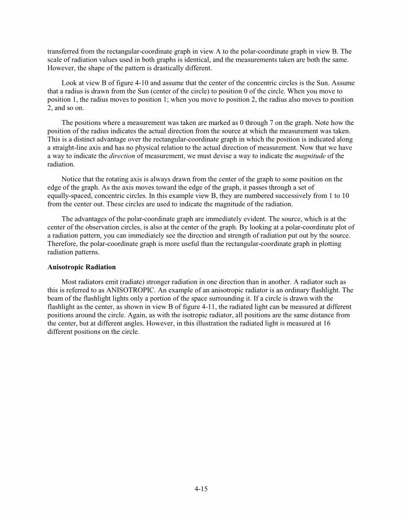
4-15
transferred from the rectangular-coordinate graph in view A to the polar-coordinate graph in view B. The scale of radiation values used in both graphs is identical, and the measurements taken are both the same. However, the shape of the pattern is drastically different.
Look at view B of figure 4-10 and assume that the center of the concentric circles is the Sun. Assume that a radius is drawn from the Sun (center of the circle) to position 0 of the circle. When you move to position 1, the radius moves to position 1; when you move to position 2, the radius also moves to position 2, and so on.
The positions where a measurement was taken are marked as 0 through 7 on the graph. Note how the position of the radius indicates the actual direction from the source at which the measurement was taken. This is a distinct advantage over the rectangular-coordinate graph in which the position is indicated along a straight-line axis and has no physical relation to the actual direction of measurement. Now that we have a way to indicate the direction of measurement, we must devise a way to indicate the magnitude of the radiation.
Notice that the rotating axis is always drawn from the center of the graph to some position on the edge of the graph. As the axis moves toward the edge of the graph, it passes through a set of equally-spaced, concentric circles. In this example view B, they are numbered successively from 1 to 10 from the center out. These circles are used to indicate the magnitude of the radiation.
The advantages of the polar-coordinate graph are immediately evident. The source, which is at the center of the observation circles, is also at the center of the graph. By looking at a polar-coordinate plot of a radiation pattern, you can immediately see the direction and strength of radiation put out by the source. Therefore, the polar-coordinate graph is more useful than the rectangular-coordinate graph in plotting radiation patterns.
Anisotropic Radiation
Most radiators emit (radiate) stronger radiation in one direction than in another. A radiator such as this is referred to as ANISOTROPIC. An example of an anisotropic radiator is an ordinary flashlight. The beam of the flashlight lights only a portion of the space surrounding it. If a circle is drawn with the flashlight as the center, as shown in view B of figure 4-11, the radiated light can be measured at different positions around the circle. Again, as with the isotropic radiator, all positions are the same distance from the center, but at different angles. However, in this illustration the radiated light is measured at 16 different positions on the circle.
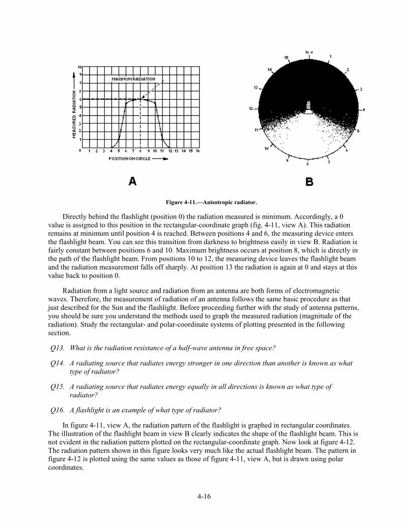
4-16
Figure 4-11.—Anisotropic radiator.
Directly behind the flashlight (position 0) the radiation measured is minimum. Accordingly, a 0 value is assigned to this position in the rectangular-coordinate graph (fig. 4-11, view A). This radiation remains at minimum until position 4 is reached. Between positions 4 and 6, the measuring device enters the flashlight beam. You can see this transition from darkness to brightness easily in view B. Radiation is fairly constant between positions 6 and 10. Maximum brightness occurs at position 8, which is directly in the path of the flashlight beam. From positions 10 to 12, the measuring device leaves the flashlight beam and the radiation measurement falls off sharply. At position 13 the radiation is again at 0 and stays at this value back to position 0.
Radiation from a light source and radiation from an antenna are both forms of electromagnetic waves. Therefore, the measurement of radiation of an antenna follows the same basic procedure as that just described for the Sun and the flashlight. Before proceeding further with the study of antenna patterns, you should be sure you understand the methods used to graph the measured radiation (magnitude of the radiation). Study the rectangular- and polar-coordinate systems of plotting presented in the following section.
Q13. What is the radiation resistance of a half-wave antenna in free space?
Q14. A radiating source that radiates energy stronger in one direction than another is known as what type of radiator?
Q15. A radiating source that radiates energy equally in all directions is known as what type of radiator?
Q16. A flashlight is an example of what type of radiator?
In figure 4-11, view A, the radiation pattern of the flashlight is graphed in rectangular coordinates. The illustration of the flashlight beam in view B clearly indicates the shape of the flashlight beam. This is not evident in the radiation pattern plotted on the rectangular-coordinate graph. Now look at figure 4-12. The radiation pattern shown in this figure looks very much like the actual flashlight beam. The pattern in figure 4-12 is plotted using the same values as those of figure 4-11, view A, but is drawn using polar coordinates.
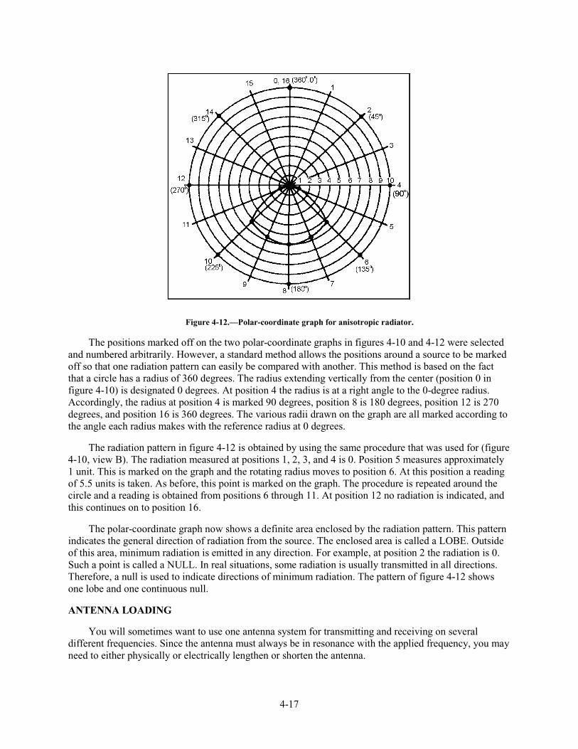
4-17
Figure 4-12.—Polar-coordinate graph for anisotropic radiator.
The positions marked off on the two polar-coordinate graphs in figures 4-10 and 4-12 were selected and numbered arbitrarily. However, a standard method allows the positions around a source to be marked off so that one radiation pattern can easily be compared with another. This method is based on the fact that a circle has a radius of 360 degrees. The radius extending vertically from the center (position 0 in figure 4-10) is designated 0 degrees. At position 4 the radius is at a right angle to the 0-degree radius. Accordingly, the radius at position 4 is marked 90 degrees, position 8 is 180 degrees, position 12 is 270 degrees, and position 16 is 360 degrees. The various radii drawn on the graph are all marked according to the angle each radius makes with the reference radius at 0 degrees.
The radiation pattern in figure 4-12 is obtained by using the same procedure that was used for (figure 4-10, view B). The radiation measured at positions 1, 2, 3, and 4 is 0. Position 5 measures approximately 1 unit. This is marked on the graph and the rotating radius moves to position 6. At this position a reading of 5.5 units is taken. As before, this point is marked on the graph. The procedure is repeated around the circle and a reading is obtained from positions 6 through 11. At position 12 no radiation is indicated, and this continues on to position 16.
The polar-coordinate graph now shows a definite area enclosed by the radiation pattern. This pattern indicates the general direction of radiation from the source. The enclosed area is called a LOBE. Outside of this area, minimum radiation is emitted in any direction. For example, at position 2 the radiation is 0. Such a point is called a NULL. In real situations, some radiation is usually transmitted in all directions. Therefore, a null is used to indicate directions of minimum radiation. The pattern of figure 4-12 shows one lobe and one continuous null.
ANTENNA LOADING
You will sometimes want to use one antenna system for transmitting and receiving on several different frequencies. Since the antenna must always be in resonance with the applied frequency, you may need to either physically or electrically lengthen or shorten the antenna.
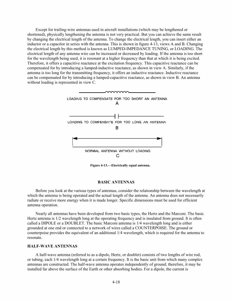
4-18
Except for trailing-wire antennas used in aircraft installations (which may be lengthened or shortened), physically lengthening the antenna is not very practical. But you can achieve the same result by changing the electrical length of the antenna. To change the electrical length, you can insert either an inductor or a capacitor in series with the antenna. This is shown in figure 4-13, views A and B. Changing the electrical length by this method is known as LUMPED-IMPEDANCE TUNING, or LOADING. The electrical length of any antenna wire can be increased or decreased by loading. If the antenna is too short for the wavelength being used, it is resonant at a higher frequency than that at which it is being excited. Therefore, it offers a capacitive reactance at the excitation frequency. This capacitive reactance can be compensated for by introducing a lumped-inductive reactance, as shown in view A. Similarly, if the antenna is too long for the transmitting frequency, it offers an inductive reactance. Inductive reactance can be compensated for by introducing a lumped-capacitive reactance, as shown in view B. An antenna without loading is represented in view C.
Figure 4-13.—Electrically equal antenna.
BASIC ANTENNAS
Before you look at the various types of antennas, consider the relationship between the wavelength at which the antenna is being operated and the actual length of the antenna. An antenna does not necessarily radiate or receive more energy when it is made longer. Specific dimensions must be used for efficient antenna operation.
Nearly all antennas have been developed from two basic types, the Hertz and the Marconi. The basic Hertz antenna is 1/2 wavelength long at the operating frequency and is insulated from ground. It is often called a DIPOLE or a DOUBLET. The basic Marconi antenna is 1/4 wavelength long and is either grounded at one end or connected to a network of wires called a COUNTERPOISE. The ground or counterpoise provides the equivalent of an additional 1/4 wavelength, which is required for the antenna to resonate.
HALF-WAVE ANTENNAS
A half-wave antenna (referred to as a dipole, Hertz, or doublet) consists of two lengths of wire rod, or tubing, each 1/4 wavelength long at a certain frequency. It is the basic unit from which many complex antennas are constructed. The half-wave antenna operates independently of ground; therefore, it may be installed far above the surface of the Earth or other absorbing bodies. For a dipole, the current is
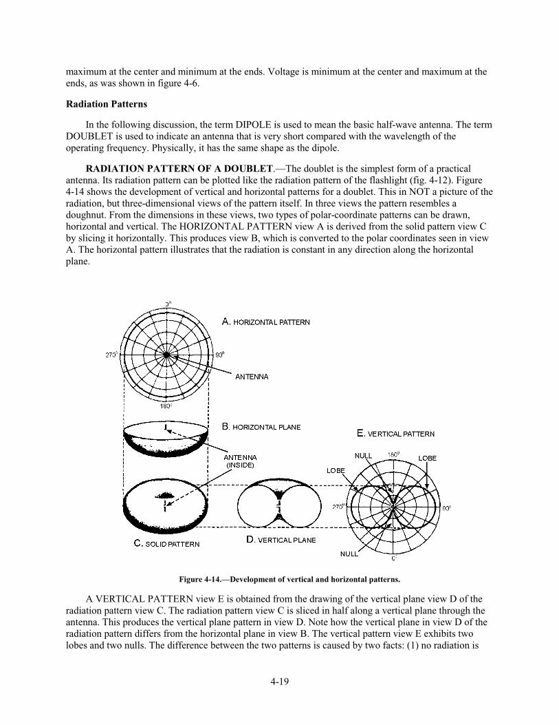
4-19
maximum at the center and minimum at the ends. Voltage is minimum at the center and maximum at the ends, as was shown in figure 4-6.
Radiation Patterns
In the following discussion, the term DIPOLE is used to mean the basic half-wave antenna. The term DOUBLET is used to indicate an antenna that is very short compared with the wavelength of the operating frequency. Physically, it has the same shape as the dipole.
RADIATION PATTERN OF A DOUBLET.—The doublet is the simplest form of a practical antenna. Its radiation pattern can be plotted like the radiation pattern of the flashlight (fig. 4-12). Figure 4-14 shows the development of vertical and horizontal patterns for a doublet. This in NOT a picture of the radiation, but three-dimensional views of the pattern itself. In three views the pattern resembles a doughnut. From the dimensions in these views, two types of polar-coordinate patterns can be drawn, horizontal and vertical. The HORIZONTAL PATTERN view A is derived from the solid pattern view C by slicing it horizontally. This produces view B, which is converted to the polar coordinates seen in view A. The horizontal pattern illustrates that the radiation is constant in any direction along the horizontal plane.
Figure 4-14.—Development of vertical and horizontal patterns.
A VERTICAL PATTERN view E is obtained from the drawing of the vertical plane view D of the radiation pattern view C. The radiation pattern view C is sliced in half along a vertical plane through the antenna. This produces the vertical plane pattern in view D. Note how the vertical plane in view D of the radiation pattern differs from the horizontal plane in view B. The vertical pattern view E exhibits two lobes and two nulls. The difference between the two patterns is caused by two facts: (1) no radiation is
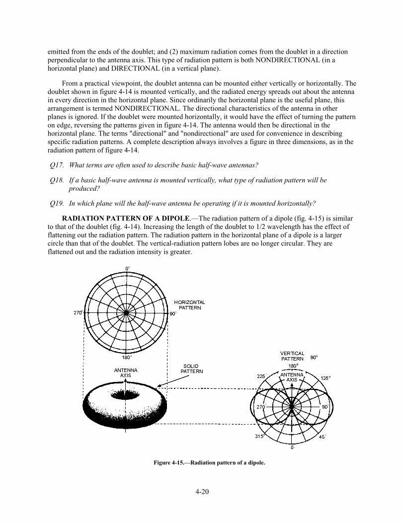
4-20
emitted from the ends of the doublet; and (2) maximum radiation comes from the doublet in a direction perpendicular to the antenna axis. This type of radiation pattern is both NONDIRECTIONAL (in a horizontal plane) and DIRECTIONAL (in a vertical plane).
From a practical viewpoint, the doublet antenna can be mounted either vertically or horizontally. The doublet shown in figure 4-14 is mounted vertically, and the radiated energy spreads out about the antenna in every direction in the horizontal plane. Since ordinarily the horizontal plane is the useful plane, this arrangement is termed NONDIRECTIONAL. The directional characteristics of the antenna in other planes is ignored. If the doublet were mounted horizontally, it would have the effect of turning the pattern on edge, reversing the patterns given in figure 4-14. The antenna would then be directional in the horizontal plane. The terms "directional" and "nondirectional" are used for convenience in describing specific radiation patterns. A complete description always involves a figure in three dimensions, as in the radiation pattern of figure 4-14.
Q17. What terms are often used to describe basic half-wave antennas?
Q18. If a basic half-wave antenna is mounted vertically, what type of radiation pattern will be produced?
Q19. In which plane will the half-wave antenna be operating if it is mounted horizontally?
RADIATION PATTERN OF A DIPOLE.—The radiation pattern of a dipole (fig. 4-15) is similar to that of the doublet (fig. 4-14). Increasing the length of the doublet to 1/2 wavelength has the effect of flattening out the radiation pattern. The radiation pattern in the horizontal plane of a dipole is a larger circle than that of the doublet. The vertical-radiation pattern lobes are no longer circular. They are flattened out and the radiation intensity is greater.
Figure 4-15.—Radiation pattern of a dipole.
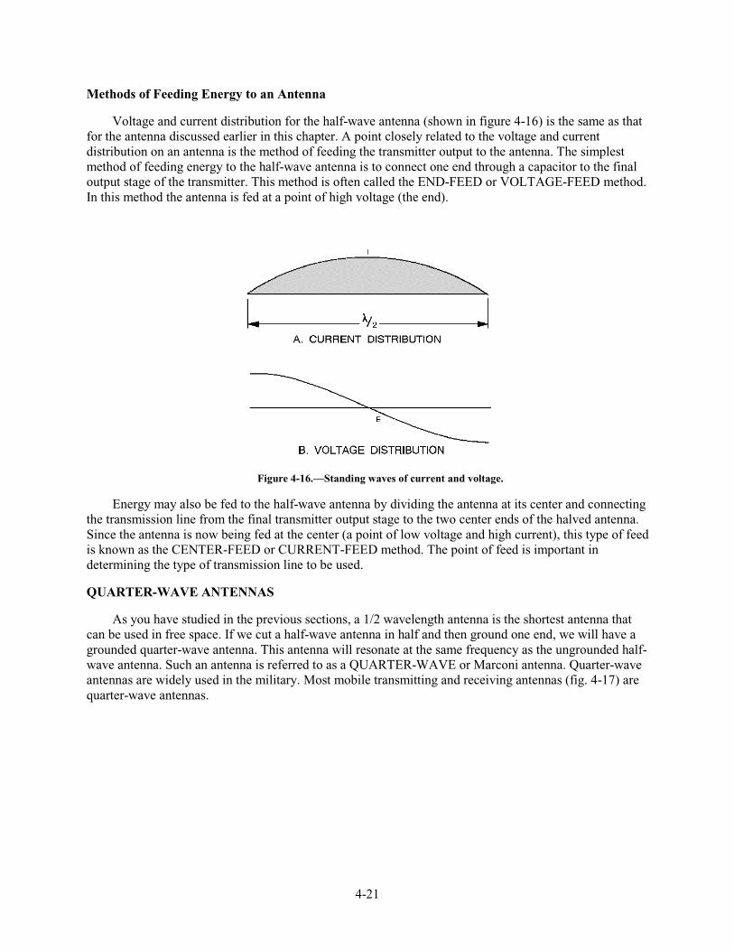
4-21
Methods of Feeding Energy to an Antenna
Voltage and current distribution for the half-wave antenna (shown in figure 4-16) is the same as that for the antenna discussed earlier in this chapter. A point closely related to the voltage and current distribution on an antenna is the method of feeding the transmitter output to the antenna. The simplest method of feeding energy to the half-wave antenna is to connect one end through a capacitor to the final output stage of the transmitter. This method is often called the END-FEED or VOLTAGE-FEED method. In this method the antenna is fed at a point of high voltage (the end).
Figure 4-16.—Standing waves of current and voltage.
Energy may also be fed to the half-wave antenna by dividing the antenna at its center and connecting the transmission line from the final transmitter output stage to the two center ends of the halved antenna. Since the antenna is now being fed at the center (a point of low voltage and high current), this type of feed is known as the CENTER-FEED or CURRENT-FEED method. The point of feed is important in determining the type of transmission line to be used.
QUARTER-WAVE ANTENNAS
As you have studied in the previous sections, a 1/2 wavelength antenna is the shortest antenna that can be used in free space. If we cut a half-wave antenna in half and then ground one end, we will have a grounded quarter-wave antenna. This antenna will resonate at the same frequency as the ungrounded half-wave antenna. Such an antenna is referred to as a QUARTER-WAVE or Marconi antenna. Quarter-wave antennas are widely used in the military. Most mobile transmitting and receiving antennas (fig. 4-17) are quarter-wave antennas.
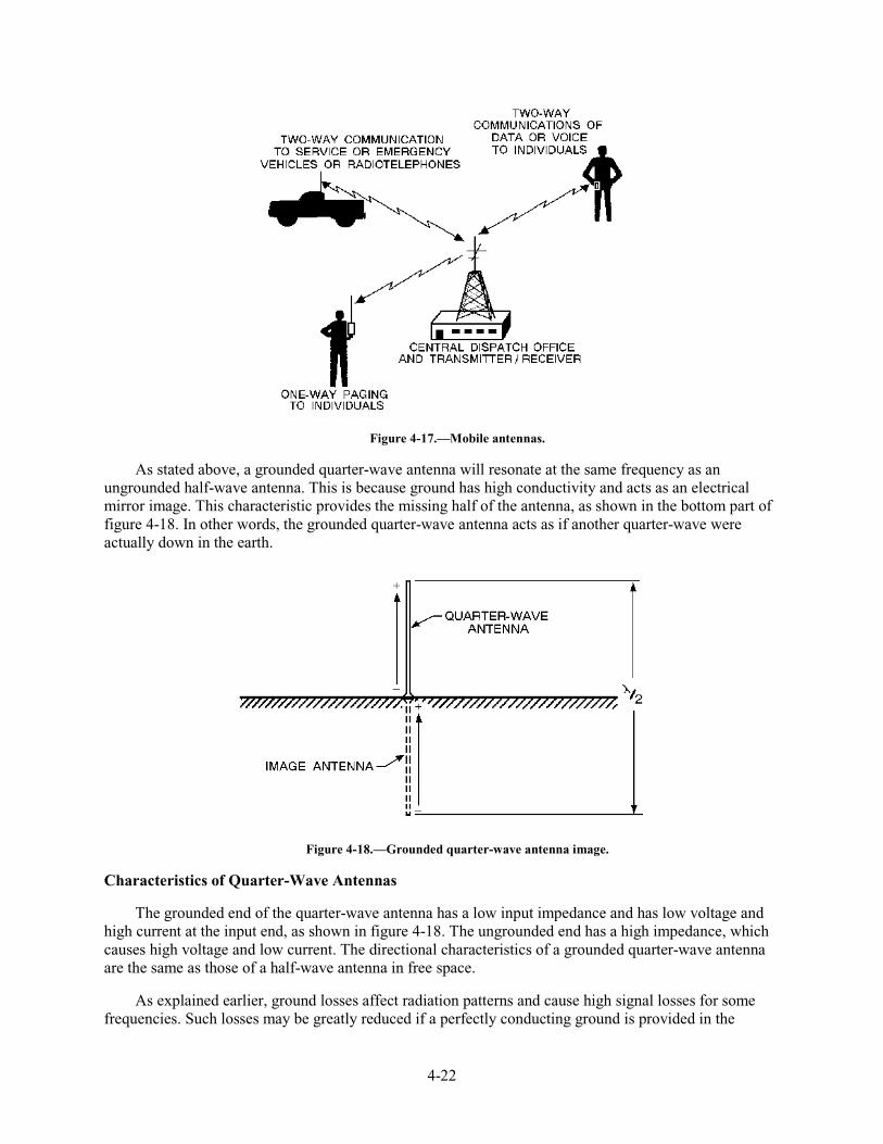
4-22
Figure 4-17.—Mobile antennas.
As stated above, a grounded quarter-wave antenna will resonate at the same frequency as an ungrounded half-wave antenna. This is because ground has high conductivity and acts as an electrical mirror image. This characteristic provides the missing half of the antenna, as shown in the bottom part of figure 4-18. In other words, the grounded quarter-wave antenna acts as if another quarter-wave were actually down in the earth.
Figure 4-18.—Grounded quarter-wave antenna image.
Characteristics of Quarter-Wave Antennas
The grounded end of the quarter-wave antenna has a low input impedance and has low voltage and high current at the input end, as shown in figure 4-18. The ungrounded end has a high impedance, which causes high voltage and low current. The directional characteristics of a grounded quarter-wave antenna are the same as those of a half-wave antenna in free space.
As explained earlier, ground losses affect radiation patterns and cause high signal losses for some frequencies. Such losses may be greatly reduced if a perfectly conducting ground is provided in the
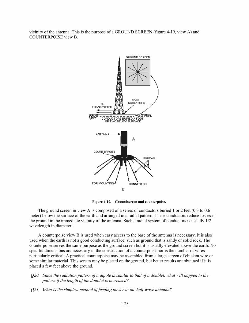
4-23
vicinity of the antenna. This is the purpose of a GROUND SCREEN (figure 4-19, view A) and COUNTERPOISE view B.
Figure 4-19.—Groundscreen and counterpoise.
The ground screen in view A is composed of a series of conductors buried 1 or 2 feet (0.3 to 0.6 meter) below the surface of the earth and arranged in a radial pattern. These conductors reduce losses in the ground in the immediate vicinity of the antenna. Such a radial system of conductors is usually 1/2 wavelength in diameter.
A counterpoise view B is used when easy access to the base of the antenna is necessary. It is also used when the earth is not a good conducting surface, such as ground that is sandy or solid rock. The counterpoise serves the same purpose as the ground screen but it is usually elevated above the earth. No specific dimensions are necessary in the construction of a counterpoise nor is the number of wires particularly critical. A practical counterpoise may be assembled from a large screen of chicken wire or some similar material. This screen may be placed on the ground, but better results are obtained if it is placed a few feet above the ground.
Q20. Since the radiation pattern of a dipole is similar to that of a doublet, what will happen to the pattern if the length of the doublet is increased?
Q21. What is the simplest method of feeding power to the half-wave antenna?
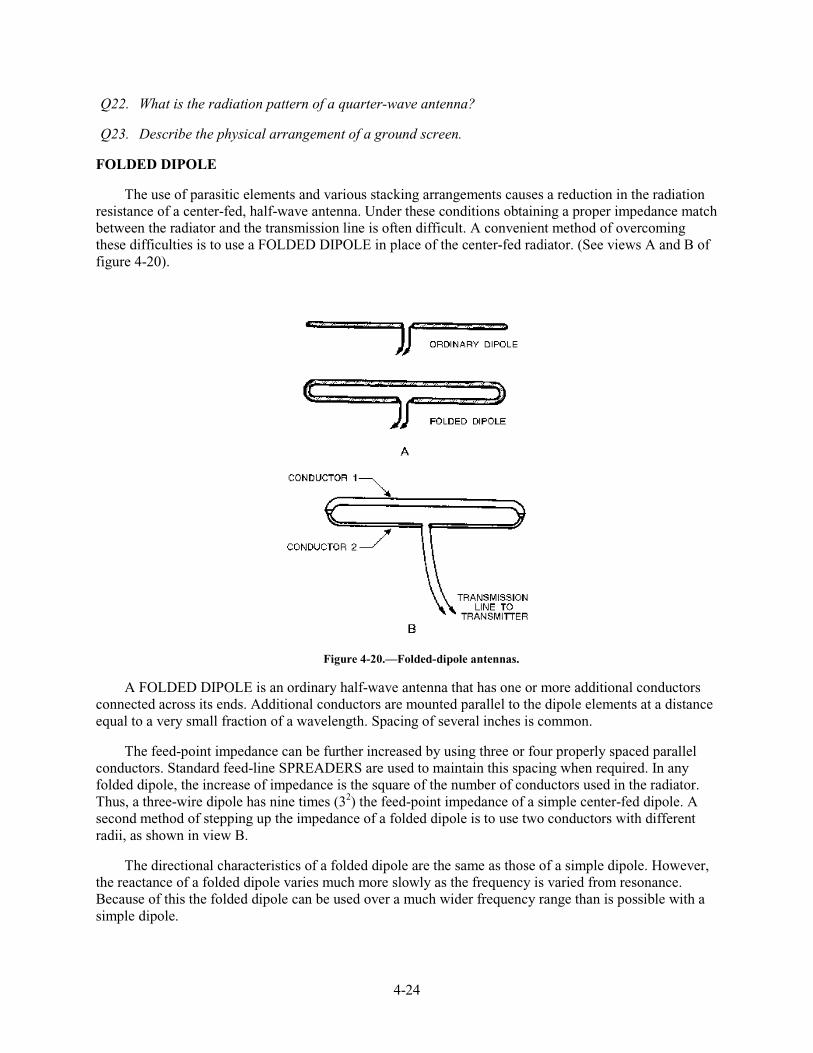
4-24
Q22. What is the radiation pattern of a quarter-wave antenna?
Q23. Describe the physical arrangement of a ground screen.
FOLDED DIPOLE
The use of parasitic elements and various stacking arrangements causes a reduction in the radiation resistance of a center-fed, half-wave antenna. Under these conditions obtaining a proper impedance match between the radiator and the transmission line is often difficult. A convenient method of overcoming these difficulties is to use a FOLDED DIPOLE in place of the center-fed radiator. (See views A and B of figure 4-20).
Figure 4-20.—Folded-dipole antennas.
A FOLDED DIPOLE is an ordinary half-wave antenna that has one or more additional conductors connected across its ends. Additional conductors are mounted parallel to the dipole elements at a distance equal to a very small fraction of a wavelength. Spacing of several inches is common.
The feed-point impedance can be further increased by using three or four properly spaced parallel conductors. Standard feed-line SPREADERS are used to maintain this spacing when required. In any folded dipole, the increase of impedance is the square of the number of conductors used in the radiator. Thus, a three-wire dipole has nine times (32) the feed-point impedance of a simple center-fed dipole. A second method of stepping up the impedance of a folded dipole is to use two conductors with different radii, as shown in view B.
The directional characteristics of a folded dipole are the same as those of a simple dipole. However, the reactance of a folded dipole varies much more slowly as the frequency is varied from resonance. Because of this the folded dipole can be used over a much wider frequency range than is possible with a simple dipole.
4-25
Q24. What is the difference in the amount of impedance between a three-wire dipole and a simple center-fed dipole?
Q25. Which has a wider frequency range, a simple dipole or a folded dipole?
ARRAY ANTENNAS
An array antenna is a special arrangement of basic antenna components involving new factors and concepts. Before you begin studying about arrays, you need to study some new terminology.
DEFINITION OF TERMS
An array antenna is made up of more than one ELEMENT, but the basic element is generally the dipole. Sometimes the basic element is made longer or shorter than a half-wave, but the deviation usually is not great.
A DRIVEN element is similar to the dipole you have been studying and is connected directly to the transmission line. It obtains its power directly from the transmitter or, as a receiving antenna, it delivers the received energy directly to the receiver. A PARASITIC ELEMENT is located near the driven element from which it gets its power. It is placed close enough to the driven element to permit coupling.
A parasitic element is sometimes placed so it will produce maximum radiation (during transmission) from its associated driver. When it operates to reinforce energy coming from the driver toward itself, the parasitic element is referred to as a DIRECTOR. If a parasitic element is placed so it causes maximum energy radiation in a direction away from itself and toward the driven element, that parasitic element is called a REFLECTOR.
If all of the elements in an array are driven, the array is referred to as a DRIVEN ARRAY (sometimes as a CONNECTED ARRAY). If one or more elements are parasitic, the entire system usually is considered to be a PARASITIC ARRAY.
MULTIELEMENT ARRAYS frequently are classified according to their directivity. A BIDIRECTIONAL ARRAY radiates in opposite directions along the line of maximum radiation. A UNIDIRECTIONAL ARRAY radiates in only one general direction.
Arrays can be described with respect to their radiation patterns and the types of elements of which they are made. However, you will find it useful to identify them by the physical placement of the elements and the direction of radiation with respect to these elements. Generally speaking, the term BROADSIDE ARRAY designates an array in which the direction of maximum radiation is perpendicular to the plane containing these elements. In actual practice, this term is confined to those arrays in which the elements themselves are also broadside, or parallel, with respect to each other.
A COLLINEAR ARRAY is one in which all the elements lie in a straight line with no radiation at the ends of the array. The direction of maximum radiation is perpendicular to the axis of the elements.
An END-FIRE ARRAY is one in which the principal direction of radiation is along the plane of the array and perpendicular to the elements. Radiation is from the end of the array, which is the reason this arrangement is referred to as an end-fire array.
Sometimes a system uses the characteristics of more than one of the three types mentioned. For instance, some of the elements may be collinear while others may be parallel. Such an arrangement is
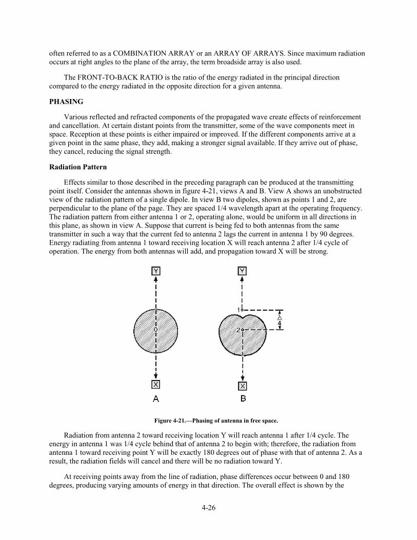
4-26
often referred to as a COMBINATION ARRAY or an ARRAY OF ARRAYS. Since maximum radiation occurs at right angles to the plane of the array, the term broadside array is also used.
The FRONT-TO-BACK RATIO is the ratio of the energy radiated in the principal direction compared to the energy radiated in the opposite direction for a given antenna.
PHASING
Various reflected and refracted components of the propagated wave create effects of reinforcement and cancellation. At certain distant points from the transmitter, some of the wave components meet in space. Reception at these points is either impaired or improved. If the different components arrive at a given point in the same phase, they add, making a stronger signal available. If they arrive out of phase, they cancel, reducing the signal strength.
Radiation Pattern
Effects similar to those described in the preceding paragraph can be produced at the transmitting point itself. Consider the antennas shown in figure 4-21, views A and B. View A shows an unobstructed view of the radiation pattern of a single dipole. In view B two dipoles, shown as points 1 and 2, are perpendicular to the plane of the page. They are spaced 1/4 wavelength apart at the operating frequency. The radiation pattern from either antenna 1 or 2, operating alone, would be uniform in all directions in this plane, as shown in view A. Suppose that current is being fed to both antennas from the same transmitter in such a way that the current fed to antenna 2 lags the current in antenna 1 by 90 degrees. Energy radiating from antenna 1 toward receiving location X will reach antenna 2 after 1/4 cycle of operation. The energy from both antennas will add, and propagation toward X will be strong.
Figure 4-21.—Phasing of antenna in free space.
Radiation from antenna 2 toward receiving location Y will reach antenna 1 after 1/4 cycle. The energy in antenna 1 was 1/4 cycle behind that of antenna 2 to begin with; therefore, the radiation from antenna 1 toward receiving point Y will be exactly 180 degrees out of phase with that of antenna 2. As a result, the radiation fields will cancel and there will be no radiation toward Y.
At receiving points away from the line of radiation, phase differences occur between 0 and 180 degrees, producing varying amounts of energy in that direction. The overall effect is shown by the
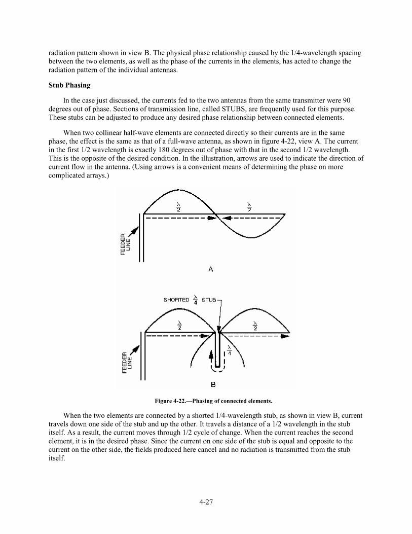
4-27
radiation pattern shown in view B. The physical phase relationship caused by the 1/4-wavelength spacing between the two elements, as well as the phase of the currents in the elements, has acted to change the radiation pattern of the individual antennas.
Stub Phasing
In the case just discussed, the currents fed to the two antennas from the same transmitter were 90 degrees out of phase. Sections of transmission line, called STUBS, are frequently used for this purpose. These stubs can be adjusted to produce any desired phase relationship between connected elements.
When two collinear half-wave elements are connected directly so their currents are in the same phase, the effect is the same as that of a full-wave antenna, as shown in figure 4-22, view A. The current in the first 1/2 wavelength is exactly 180 degrees out of phase with that in the second 1/2 wavelength. This is the opposite of the desired condition. In the illustration, arrows are used to indicate the direction of current flow in the antenna. (Using arrows is a convenient means of determining the phase on more complicated arrays.)
Figure 4-22.—Phasing of connected elements.
When the two elements are connected by a shorted 1/4-wavelength stub, as shown in view B, current travels down one side of the stub and up the other. It travels a distance of a 1/2 wavelength in the stub itself. As a result, the current moves through 1/2 cycle of change. When the current reaches the second element, it is in the desired phase. Since the current on one side of the stub is equal and opposite to the current on the other side, the fields produced here cancel and no radiation is transmitted from the stub itself.
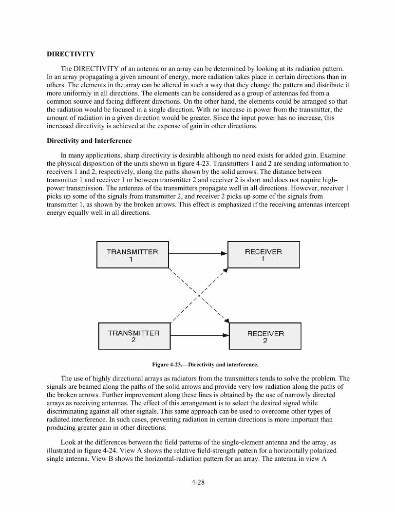
4-28
DIRECTIVITY
The DIRECTIVITY of an antenna or an array can be determined by looking at its radiation pattern. In an array propagating a given amount of energy, more radiation takes place in certain directions than in others. The elements in the array can be altered in such a way that they change the pattern and distribute it more uniformly in all directions. The elements can be considered as a group of antennas fed from a common source and facing different directions. On the other hand, the elements could be arranged so that the radiation would be focused in a single direction. With no increase in power from the transmitter, the amount of radiation in a given direction would be greater. Since the input power has no increase, this increased directivity is achieved at the expense of gain in other directions.
Directivity and Interference
In many applications, sharp directivity is desirable although no need exists for added gain. Examine the physical disposition of the units shown in figure 4-23. Transmitters 1 and 2 are sending information to receivers 1 and 2, respectively, along the paths shown by the solid arrows. The distance between transmitter 1 and receiver 1 or between transmitter 2 and receiver 2 is short and does not require high-power transmission. The antennas of the transmitters propagate well in all directions. However, receiver 1 picks up some of the signals from transmitter 2, and receiver 2 picks up some of the signals from transmitter 1, as shown by the broken arrows. This effect is emphasized if the receiving antennas intercept energy equally well in all directions.
Figure 4-23.—Directivity and interference.
The use of highly directional arrays as radiators from the transmitters tends to solve the problem. The signals are beamed along the paths of the solid arrows and provide very low radiation along the paths of the broken arrows. Further improvement along these lines is obtained by the use of narrowly directed arrays as receiving antennas. The effect of this arrangement is to select the desired signal while discriminating against all other signals. This same approach can be used to overcome other types of radiated interference. In such cases, preventing radiation in certain directions is more important than producing greater gain in other directions.
Look at the differences between the field patterns of the single-element antenna and the array, as illustrated in figure 4-24. View A shows the relative field-strength pattern for a horizontally polarized single antenna. View B shows the horizontal-radiation pattern for an array. The antenna in view A
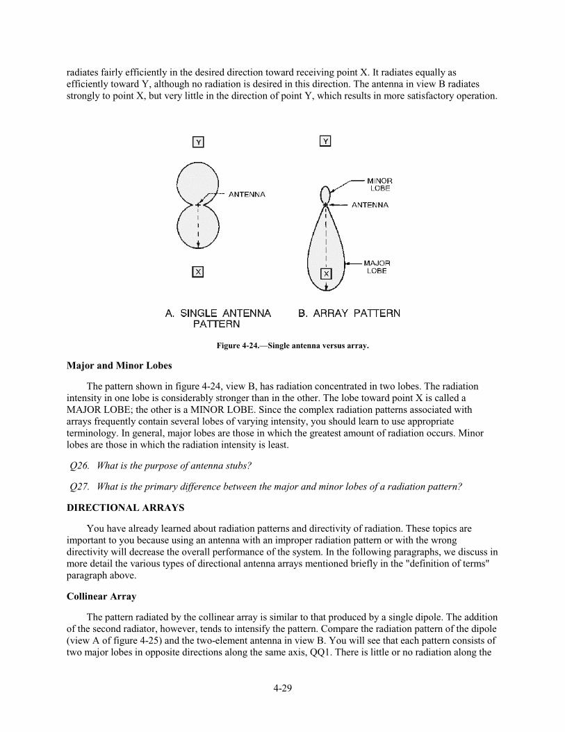
4-29
radiates fairly efficiently in the desired direction toward receiving point X. It radiates equally as efficiently toward Y, although no radiation is desired in this direction. The antenna in view B radiates strongly to point X, but very little in the direction of point Y, which results in more satisfactory operation.
Figure 4-24.—Single antenna versus array.
Major and Minor Lobes
The pattern shown in figure 4-24, view B, has radiation concentrated in two lobes. The radiation intensity in one lobe is considerably stronger than in the other. The lobe toward point X is called a MAJOR LOBE; the other is a MINOR LOBE. Since the complex radiation patterns associated with arrays frequently contain several lobes of varying intensity, you should learn to use appropriate terminology. In general, major lobes are those in which the greatest amount of radiation occurs. Minor lobes are those in which the radiation intensity is least.
Q26. What is the purpose of antenna stubs?
Q27. What is the primary difference between the major and minor lobes of a radiation pattern?
DIRECTIONAL ARRAYS
You have already learned about radiation patterns and directivity of radiation. These topics are important to you because using an antenna with an improper radiation pattern or with the wrong directivity will decrease the overall performance of the system. In the following paragraphs, we discuss in more detail the various types of directional antenna arrays mentioned briefly in the "definition of terms" paragraph above.
Collinear Array
The pattern radiated by the collinear array is similar to that produced by a single dipole. The addition of the second radiator, however, tends to intensify the pattern. Compare the radiation pattern of the dipole (view A of figure 4-25) and the two-element antenna in view B. You will see that each pattern consists of two major lobes in opposite directions along the same axis, QQ1. There is little or no radiation along the
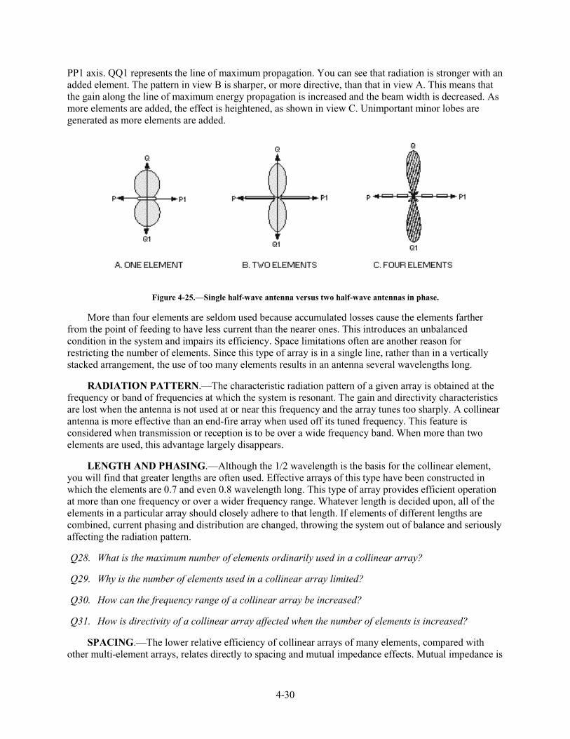
4-30
PP1 axis. QQ1 represents the line of maximum propagation. You can see that radiation is stronger with an added element. The pattern in view B is sharper, or more directive, than that in view A. This means that the gain along the line of maximum energy propagation is increased and the beam width is decreased. As more elements are added, the effect is heightened, as shown in view C. Unimportant minor lobes are generated as more elements are added.
Figure 4-25.—Single half-wave antenna versus two half-wave antennas in phase.
More than four elements are seldom used because accumulated losses cause the elements farther from the point of feeding to have less current than the nearer ones. This introduces an unbalanced condition in the system and impairs its efficiency. Space limitations often are another reason for restricting the number of elements. Since this type of array is in a single line, rather than in a vertically stacked arrangement, the use of too many elements results in an antenna several wavelengths long.
RADIATION PATTERN.—The characteristic radiation pattern of a given array is obtained at the frequency or band of frequencies at which the system is resonant. The gain and directivity characteristics are lost when the antenna is not used at or near this frequency and the array tunes too sharply. A collinear antenna is more effective than an end-fire array when used off its tuned frequency. This feature is considered when transmission or reception is to be over a wide frequency band. When more than two elements are used, this advantage largely disappears.
LENGTH AND PHASING.—Although the 1/2 wavelength is the basis for the collinear element, you will find that greater lengths are often used. Effective arrays of this type have been constructed in which the elements are 0.7 and even 0.8 wavelength long. This type of array provides efficient operation at more than one frequency or over a wider frequency range. Whatever length is decided upon, all of the elements in a particular array should closely adhere to that length. If elements of different lengths are combined, current phasing and distribution are changed, throwing the system out of balance and seriously affecting the radiation pattern.
Q28. What is the maximum number of elements ordinarily used in a collinear array?
Q29. Why is the number of elements used in a collinear array limited?
Q30. How can the frequency range of a collinear array be increased?
Q31. How is directivity of a collinear array affected when the number of elements is increased?
SPACING.—The lower relative efficiency of collinear arrays of many elements, compared with other multi-element arrays, relates directly to spacing and mutual impedance effects. Mutual impedance is
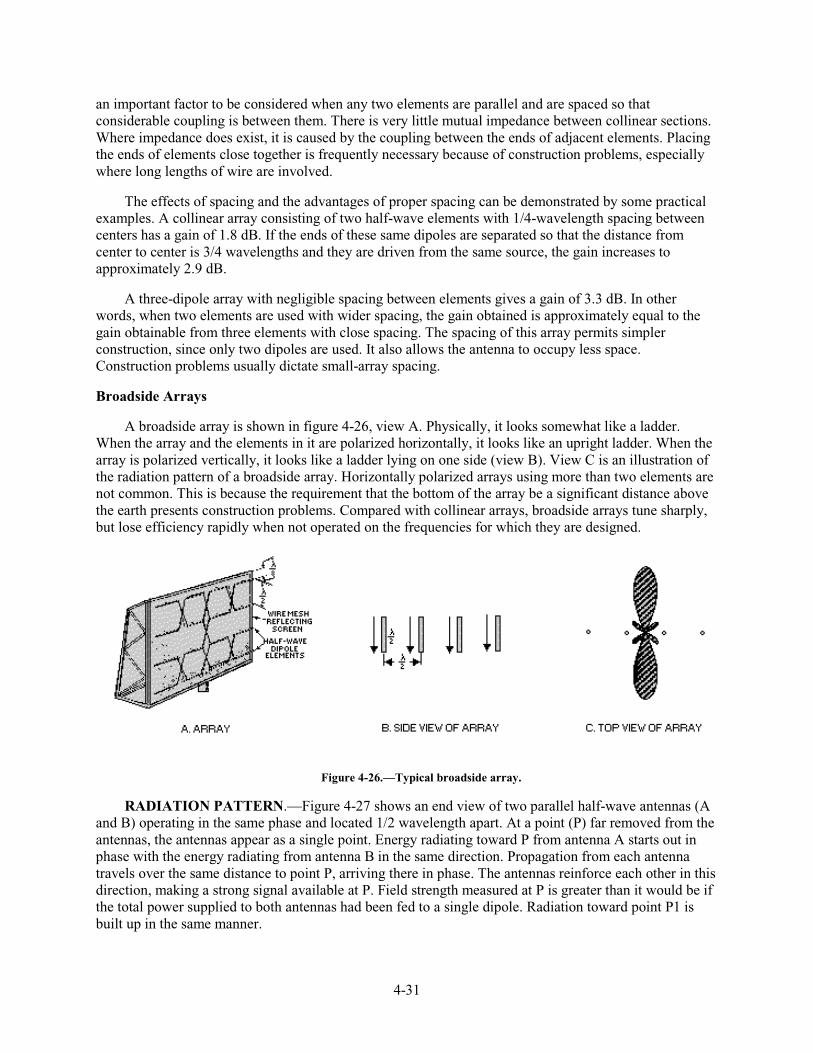
4-31
an important factor to be considered when any two elements are parallel and are spaced so that considerable coupling is between them. There is very little mutual impedance between collinear sections. Where impedance does exist, it is caused by the coupling between the ends of adjacent elements. Placing the ends of elements close together is frequently necessary because of construction problems, especially where long lengths of wire are involved.
The effects of spacing and the advantages of proper spacing can be demonstrated by some practical examples. A collinear array consisting of two half-wave elements with 1/4-wavelength spacing between centers has a gain of 1.8 dB. If the ends of these same dipoles are separated so that the distance from center to center is 3/4 wavelengths and they are driven from the same source, the gain increases to approximately 2.9 dB.
A three-dipole array with negligible spacing between elements gives a gain of 3.3 dB. In other words, when two elements are used with wider spacing, the gain obtained is approximately equal to the gain obtainable from three elements with close spacing. The spacing of this array permits simpler construction, since only two dipoles are used. It also allows the antenna to occupy less space. Construction problems usually dictate small-array spacing.
Broadside Arrays
A broadside array is shown in figure 4-26, view A. Physically, it looks somewhat like a ladder. When the array and the elements in it are polarized horizontally, it looks like an upright ladder. When the array is polarized vertically, it looks like a ladder lying on one side (view B). View C is an illustration of the radiation pattern of a broadside array. Horizontally polarized arrays using more than two elements are not common. This is because the requirement that the bottom of the array be a significant distance above the earth presents construction problems. Compared with collinear arrays, broadside arrays tune sharply, but lose efficiency rapidly when not operated on the frequencies for which they are designed.
Figure 4-26.—Typical broadside array.
RADIATION PATTERN.—Figure 4-27 shows an end view of two parallel half-wave antennas (A and B) operating in the same phase and located 1/2 wavelength apart. At a point (P) far removed from the antennas, the antennas appear as a single point. Energy radiating toward P from antenna A starts out in phase with the energy radiating from antenna B in the same direction. Propagation from each antenna travels over the same distance to point P, arriving there in phase. The antennas reinforce each other in this direction, making a strong signal available at P. Field strength measured at P is greater than it would be if the total power supplied to both antennas had been fed to a single dipole. Radiation toward point P1 is built up in the same manner.
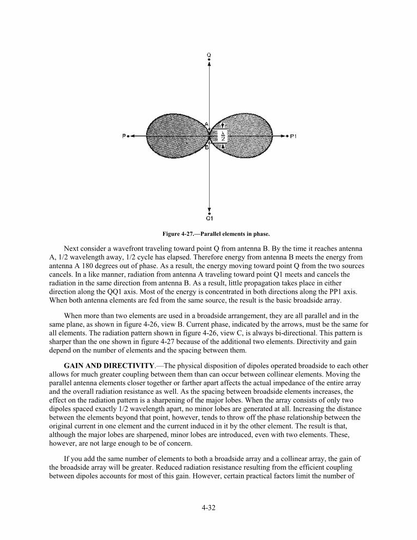
4-32
Figure 4-27.—Parallel elements in phase.
Next consider a wavefront traveling toward point Q from antenna B. By the time it reaches antenna A, 1/2 wavelength away, 1/2 cycle has elapsed. Therefore energy from antenna B meets the energy from antenna A 180 degrees out of phase. As a result, the energy moving toward point Q from the two sources cancels. In a like manner, radiation from antenna A traveling toward point Q1 meets and cancels the radiation in the same direction from antenna B. As a result, little propagation takes place in either direction along the QQ1 axis. Most of the energy is concentrated in both directions along the PP1 axis. When both antenna elements are fed from the same source, the result is the basic broadside array.
When more than two elements are used in a broadside arrangement, they are all parallel and in the same plane, as shown in figure 4-26, view B. Current phase, indicated by the arrows, must be the same for all elements. The radiation pattern shown in figure 4-26, view C, is always bi-directional. This pattern is sharper than the one shown in figure 4-27 because of the additional two elements. Directivity and gain depend on the number of elements and the spacing between them.
GAIN AND DIRECTIVITY.—The physical disposition of dipoles operated broadside to each other allows for much greater coupling between them than can occur between collinear elements. Moving the parallel antenna elements closer together or farther apart affects the actual impedance of the entire array and the overall radiation resistance as well. As the spacing between broadside elements increases, the effect on the radiation pattern is a sharpening of the major lobes. When the array consists of only two dipoles spaced exactly 1/2 wavelength apart, no minor lobes are generated at all. Increasing the distance between the elements beyond that point, however, tends to throw off the phase relationship between the original current in one element and the current induced in it by the other element. The result is that, although the major lobes are sharpened, minor lobes are introduced, even with two elements. These, however, are not large enough to be of concern.
If you add the same number of elements to both a broadside array and a collinear array, the gain of the broadside array will be greater. Reduced radiation resistance resulting from the efficient coupling between dipoles accounts for most of this gain. However, certain practical factors limit the number of
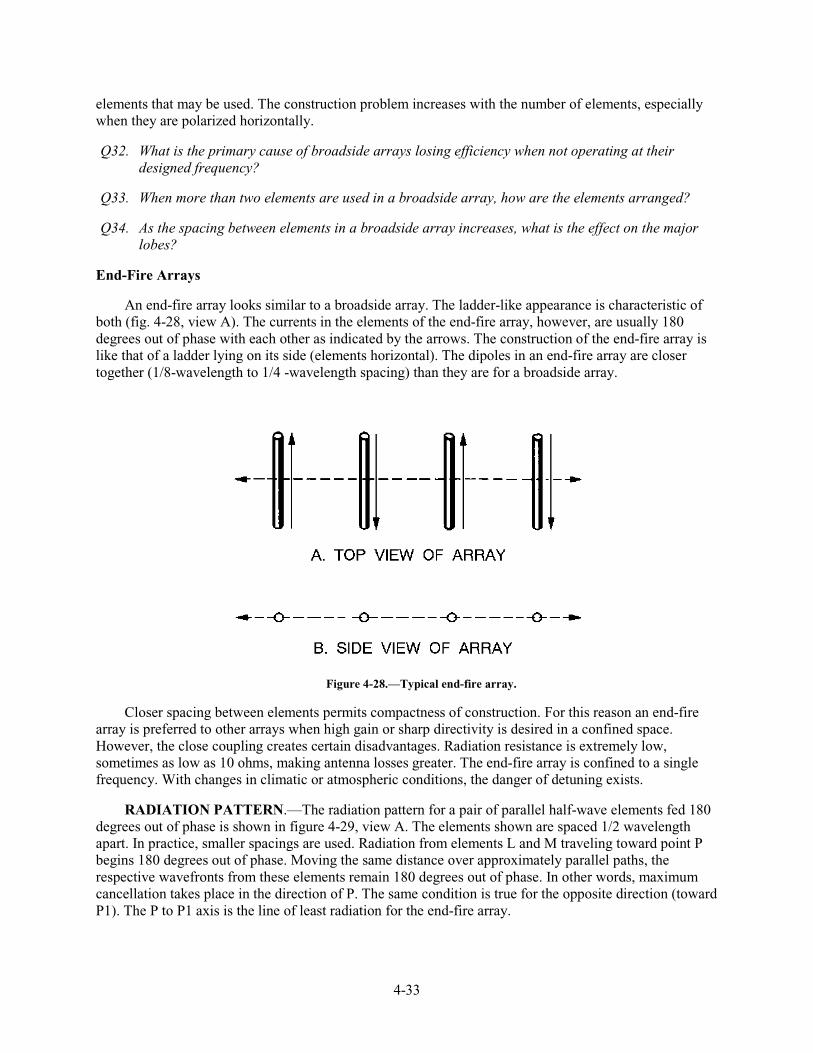
4-33
elements that may be used. The construction problem increases with the number of elements, especially when they are polarized horizontally.
Q32. What is the primary cause of broadside arrays losing efficiency when not operating at their designed frequency?
Q33. When more than two elements are used in a broadside array, how are the elements arranged?
Q34. As the spacing between elements in a broadside array increases, what is the effect on the major lobes?
End-Fire Arrays
An end-fire array looks similar to a broadside array. The ladder-like appearance is characteristic of both (fig. 4-28, view A). The currents in the elements of the end-fire array, however, are usually 180 degrees out of phase with each other as indicated by the arrows. The construction of the end-fire array is like that of a ladder lying on its side (elements horizontal). The dipoles in an end-fire array are closer together (1/8-wavelength to 1/4 -wavelength spacing) than they are for a broadside array.
Figure 4-28.—Typical end-fire array.
Closer spacing between elements permits compactness of construction. For this reason an end-fire array is preferred to other arrays when high gain or sharp directivity is desired in a confined space. However, the close coupling creates certain disadvantages. Radiation resistance is extremely low, sometimes as low as 10 ohms, making antenna losses greater. The end-fire array is confined to a single frequency. With changes in climatic or atmospheric conditions, the danger of detuning exists.
RADIATION PATTERN.—The radiation pattern for a pair of parallel half-wave elements fed 180 degrees out of phase is shown in figure 4-29, view A. The elements shown are spaced 1/2 wavelength apart. In practice, smaller spacings are used. Radiation from elements L and M traveling toward point P begins 180 degrees out of phase. Moving the same distance over approximately parallel paths, the respective wavefronts from these elements remain 180 degrees out of phase. In other words, maximum cancellation takes place in the direction of P. The same condition is true for the opposite direction (toward P1). The P to P1 axis is the line of least radiation for the end-fire array.
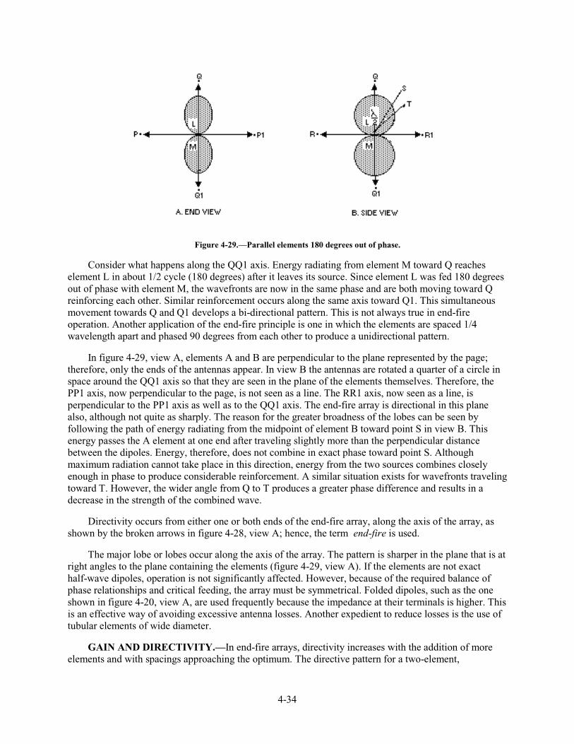
4-34
Figure 4-29.—Parallel elements 180 degrees out of phase.
Consider what happens along the QQ1 axis. Energy radiating from element M toward Q reaches element L in about 1/2 cycle (180 degrees) after it leaves its source. Since element L was fed 180 degrees out of phase with element M, the wavefronts are now in the same phase and are both moving toward Q reinforcing each other. Similar reinforcement occurs along the same axis toward Q1. This simultaneous movement towards Q and Q1 develops a bi-directional pattern. This is not always true in end-fire operation. Another application of the end-fire principle is one in which the elements are spaced 1/4 wavelength apart and phased 90 degrees from each other to produce a unidirectional pattern.
In figure 4-29, view A, elements A and B are perpendicular to the plane represented by the page; therefore, only the ends of the antennas appear. In view B the antennas are rotated a quarter of a circle in space around the QQ1 axis so that they are seen in the plane of the elements themselves. Therefore, the PP1 axis, now perpendicular to the page, is not seen as a line. The RR1 axis, now seen as a line, is perpendicular to the PP1 axis as well as to the QQ1 axis. The end-fire array is directional in this plane also, although not quite as sharply. The reason for the greater broadness of the lobes can be seen by following the path of energy radiating from the midpoint of element B toward point S in view B. This energy passes the A element at one end after traveling slightly more than the perpendicular distance between the dipoles. Energy, therefore, does not combine in exact phase toward point S. Although maximum radiation cannot take place in this direction, energy from the two sources combines closely enough in phase to produce considerable reinforcement. A similar situation exists for wavefronts traveling toward T. However, the wider angle from Q to T produces a greater phase difference and results in a decrease in the strength of the combined wave.
Directivity occurs from either one or both ends of the end-fire array, along the axis of the array, as shown by the broken arrows in figure 4-28, view A; hence, the term end-fire is used.
The major lobe or lobes occur along the axis of the array. The pattern is sharper in the plane that is at right angles to the plane containing the elements (figure 4-29, view A). If the elements are not exact half-wave dipoles, operation is not significantly affected. However, because of the required balance of phase relationships and critical feeding, the array must be symmetrical. Folded dipoles, such as the one shown in figure 4-20, view A, are used frequently because the impedance at their terminals is higher. This is an effective way of avoiding excessive antenna losses. Another expedient to reduce losses is the use of tubular elements of wide diameter.
GAIN AND DIRECTIVITY.—In end-fire arrays, directivity increases with the addition of more elements and with spacings approaching the optimum. The directive pattern for a two-element,
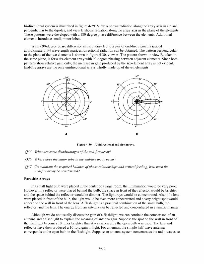
4-35
bi-directional system is illustrated in figure 4-29. View A shows radiation along the array axis in a plane perpendicular to the dipoles, and view B shows radiation along the array axis in the plane of the elements. These patterns were developed with a 180-degree phase difference between the elements. Additional elements introduce small, minor lobes.
With a 90-degree phase difference in the energy fed to a pair of end-fire elements spaced approximately 1/4 wavelength apart, unidirectional radiation can be obtained. The pattern perpendicular to the plane of the two elements is shown in figure 4-30, view A. The pattern shown in view B, taken in the same plane, is for a six-element array with 90-degree phasing between adjacent elements. Since both patterns show relative gain only, the increase in gain produced by the six-element array is not evident. End-fire arrays are the only unidirectional arrays wholly made up of driven elements.
Figure 4-30.—Unidirectional end-fire arrays.
Q35. What are some disadvantages of the end-fire array?
Q36. Where does the major lobe in the end-fire array occur?
Q37. To maintain the required balance of phase relationships and critical feeding, how must the end-fire array be constructed?
Parasitic Arrays
If a small light bulb were placed in the center of a large room, the illumination would be very poor. However, if a reflector were placed behind the bulb, the space in front of the reflector would be brighter and the space behind the reflector would be dimmer. The light rays would be concentrated. Also, if a lens were placed in front of the bulb, the light would be even more concentrated and a very bright spot would appear on the wall in front of the lens. A flashlight is a practical combination of the small bulb, the reflector, and the lens. The energy from an antenna can be reflected and concentrated in a similar manner.
Although we do not usually discuss the gain of a flashlight, we can continue the comparison of an antenna and a flashlight to explain the meaning of antenna gain. Suppose the spot on the wall in front of the flashlight becomes 10 times brighter than it was when only the open bulb was used. The lens and reflector have then produced a 10-fold gain in light. For antennas, the simple half-wave antenna corresponds to the open bulb in the flashlight. Suppose an antenna system concentrates the radio waves so
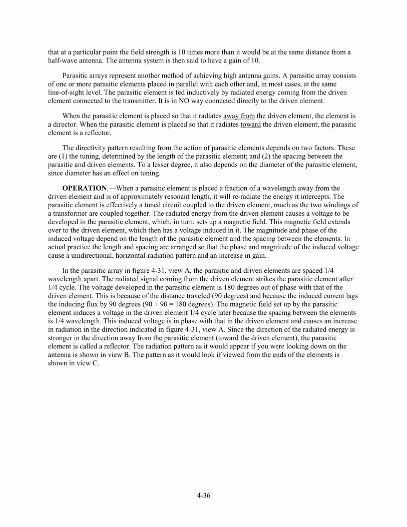
4-36
that at a particular point the field strength is 10 times more than it would be at the same distance from a half-wave antenna. The antenna system is then said to have a gain of 10.
Parasitic arrays represent another method of achieving high antenna gains. A parasitic array consists of one or more parasitic elements placed in parallel with each other and, in most cases, at the same line-of-sight level. The parasitic element is fed inductively by radiated energy coming from the driven element connected to the transmitter. It is in NO way connected directly to the driven element.
When the parasitic element is placed so that it radiates away from the driven element, the element is a director. When the parasitic element is placed so that it radiates toward the driven element, the parasitic element is a reflector.
The directivity pattern resulting from the action of parasitic elements depends on two factors. These are (1) the tuning, determined by the length of the parasitic element; and (2) the spacing between the parasitic and driven elements. To a lesser degree, it also depends on the diameter of the parasitic element, since diameter has an effect on tuning.
OPERATION.—When a parasitic element is placed a fraction of a wavelength away from the driven element and is of approximately resonant length, it will re-radiate the energy it intercepts. The parasitic element is effectively a tuned circuit coupled to the driven element, much as the two windings of a transformer are coupled together. The radiated energy from the driven element causes a voltage to be developed in the parasitic element, which, in turn, sets up a magnetic field. This magnetic field extends over to the driven element, which then has a voltage induced in it. The magnitude and phase of the induced voltage depend on the length of the parasitic element and the spacing between the elements. In actual practice the length and spacing are arranged so that the phase and magnitude of the induced voltage cause a unidirectional, horizontal-radiation pattern and an increase in gain.
In the parasitic array in figure 4-31, view A, the parasitic and driven elements are spaced 1/4 wavelength apart. The radiated signal coming from the driven element strikes the parasitic element after 1/4 cycle. The voltage developed in the parasitic element is 180 degrees out of phase with that of the driven element. This is because of the distance traveled (90 degrees) and because the induced current lags the inducing flux by 90 degrees (90 + 90 = 180 degrees). The magnetic field set up by the parasitic element induces a voltage in the driven element 1/4 cycle later because the spacing between the elements is 1/4 wavelength. This induced voltage is in phase with that in the driven element and causes an increase in radiation in the direction indicated in figure 4-31, view A. Since the direction of the radiated energy is stronger in the direction away from the parasitic element (toward the driven element), the parasitic element is called a reflector. The radiation pattern as it would appear if you were looking down on the antenna is shown in view B. The pattern as it would look if viewed from the ends of the elements is shown in view C.
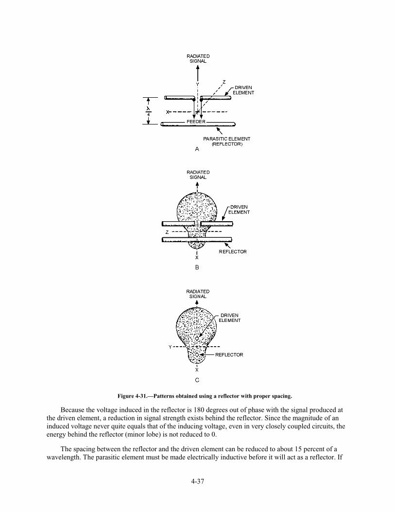
4-37
Figure 4-31.—Patterns obtained using a reflector with proper spacing.
Because the voltage induced in the reflector is 180 degrees out of phase with the signal produced at the driven element, a reduction in signal strength exists behind the reflector. Since the magnitude of an induced voltage never quite equals that of the inducing voltage, even in very closely coupled circuits, the energy behind the reflector (minor lobe) is not reduced to 0.
The spacing between the reflector and the driven element can be reduced to about 15 percent of a wavelength. The parasitic element must be made electrically inductive before it will act as a reflector. If
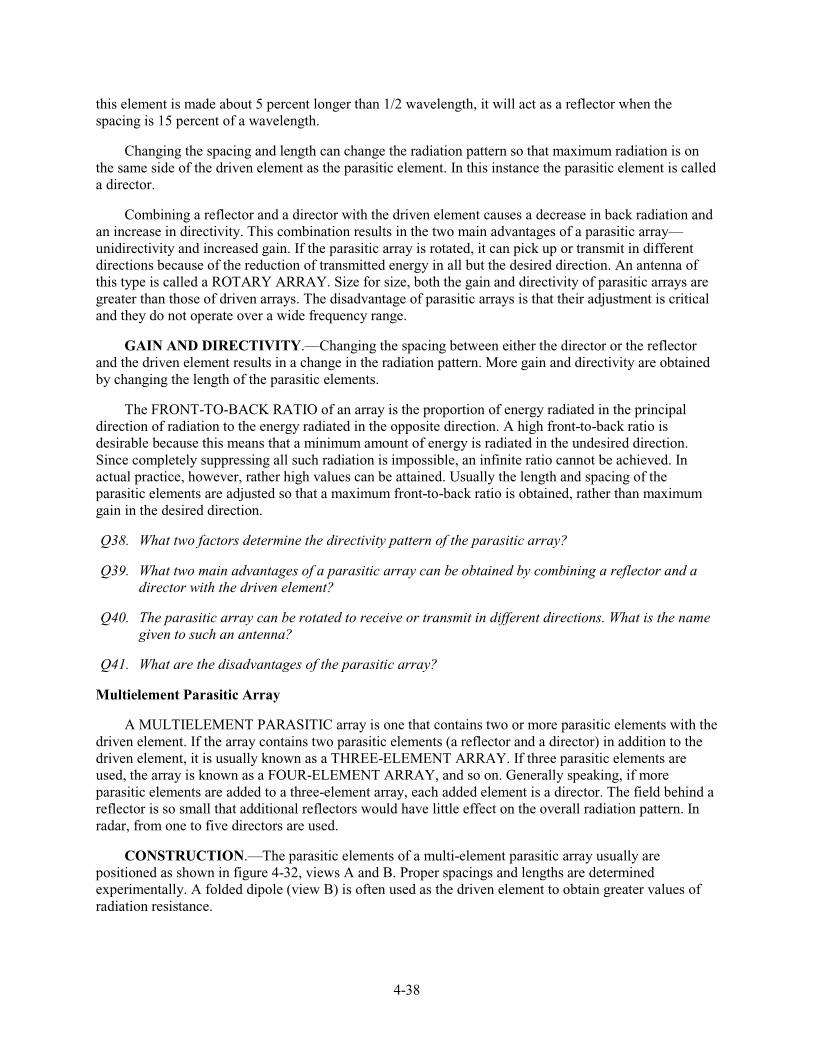
4-38
this element is made about 5 percent longer than 1/2 wavelength, it will act as a reflector when the spacing is 15 percent of a wavelength.
Changing the spacing and length can change the radiation pattern so that maximum radiation is on the same side of the driven element as the parasitic element. In this instance the parasitic element is called a director.
Combining a reflector and a director with the driven element causes a decrease in back radiation and an increase in directivity. This combination results in the two main advantages of a parasitic array—unidirectivity and increased gain. If the parasitic array is rotated, it can pick up or transmit in different directions because of the reduction of transmitted energy in all but the desired direction. An antenna of this type is called a ROTARY ARRAY. Size for size, both the gain and directivity of parasitic arrays are greater than those of driven arrays. The disadvantage of parasitic arrays is that their adjustment is critical and they do not operate over a wide frequency range.
GAIN AND DIRECTIVITY.—Changing the spacing between either the director or the reflector and the driven element results in a change in the radiation pattern. More gain and directivity are obtained by changing the length of the parasitic elements.
The FRONT-TO-BACK RATIO of an array is the proportion of energy radiated in the principal direction of radiation to the energy radiated in the opposite direction. A high front-to-back ratio is desirable because this means that a minimum amount of energy is radiated in the undesired direction. Since completely suppressing all such radiation is impossible, an infinite ratio cannot be achieved. In actual practice, however, rather high values can be attained. Usually the length and spacing of the parasitic elements are adjusted so that a maximum front-to-back ratio is obtained, rather than maximum gain in the desired direction.
Q38. What two factors determine the directivity pattern of the parasitic array?
Q39. What two main advantages of a parasitic array can be obtained by combining a reflector and a director with the driven element?
Q40. The parasitic array can be rotated to receive or transmit in different directions. What is the name given to such an antenna?
Q41. What are the disadvantages of the parasitic array?
Multielement Parasitic Array
A MULTIELEMENT PARASITIC array is one that contains two or more parasitic elements with the driven element. If the array contains two parasitic elements (a reflector and a director) in addition to the driven element, it is usually known as a THREE-ELEMENT ARRAY. If three parasitic elements are used, the array is known as a FOUR-ELEMENT ARRAY, and so on. Generally speaking, if more parasitic elements are added to a three-element array, each added element is a director. The field behind a reflector is so small that additional reflectors would have little effect on the overall radiation pattern. In radar, from one to five directors are used.
CONSTRUCTION.—The parasitic elements of a multi-element parasitic array usually are positioned as shown in figure 4-32, views A and B. Proper spacings and lengths are determined experimentally. A folded dipole (view B) is often used as the driven element to obtain greater values of radiation resistance.
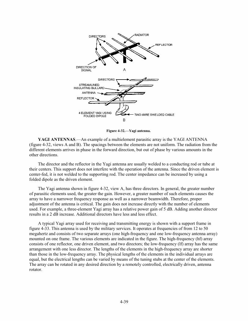
4-39
Figure 4-32.—Yagi antenna.
YAGI ANTENNAS.—An example of a multielement parasitic array is the YAGI ANTENNA (figure 4-32, views A and B). The spacings between the elements are not uniform. The radiation from the different elements arrives in phase in the forward direction, but out of phase by various amounts in the other directions.
The director and the reflector in the Yagi antenna are usually welded to a conducting rod or tube at their centers. This support does not interfere with the operation of the antenna. Since the driven element is center-fed, it is not welded to the supporting rod. The center impedance can be increased by using a folded dipole as the driven element.
The Yagi antenna shown in figure 4-32, view A, has three directors. In general, the greater number of parasitic elements used, the greater the gain. However, a greater number of such elements causes the array to have a narrower frequency response as well as a narrower beamwidth. Therefore, proper adjustment of the antenna is critical. The gain does not increase directly with the number of elements used. For example, a three-element Yagi array has a relative power gain of 5 dB. Adding another director results in a 2 dB increase. Additional directors have less and less effect.
A typical Yagi array used for receiving and transmitting energy is shown with a support frame in figure 4-33. This antenna is used by the military services. It operates at frequencies of from 12 to 50 megahertz and consists of two separate arrays (one high-frequency and one low-frequency antenna array) mounted on one frame. The various elements are indicated in the figure. The high-frequency (hf) array consists of one reflector, one driven element, and two directors; the low-frequency (lf) array has the same arrangement with one less director. The lengths of the elements in the high-frequency array are shorter than those in the low-frequency array. The physical lengths of the elements in the individual arrays are equal, but the electrical lengths can be varied by means of the tuning stubs at the center of the elements. The array can be rotated in any desired direction by a remotely controlled, electrically driven, antenna rotator.
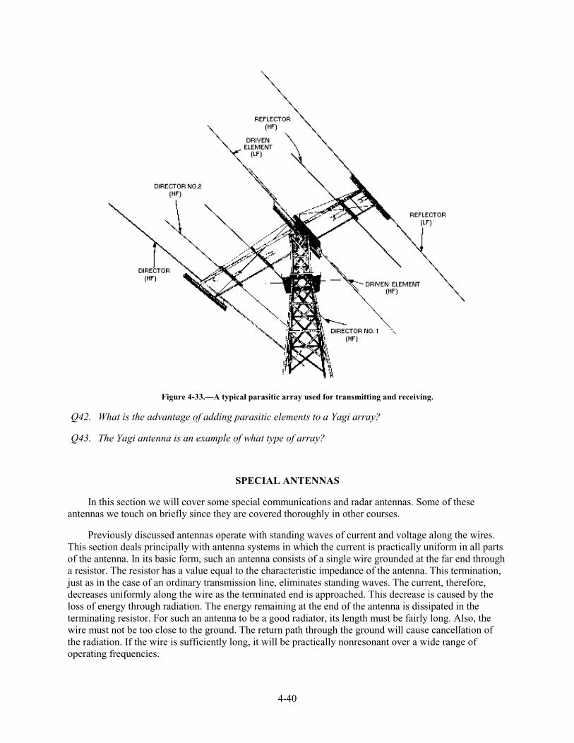
4-40
Figure 4-33.—A typical parasitic array used for transmitting and receiving.
Q42. What is the advantage of adding parasitic elements to a Yagi array?
Q43. The Yagi antenna is an example of what type of array?
SPECIAL ANTENNAS
In this section we will cover some special communications and radar antennas. Some of these antennas we touch on briefly since they are covered thoroughly in other courses.
Previously discussed antennas operate with standing waves of current and voltage along the wires. This section deals principally with antenna systems in which the current is practically uniform in all parts of the antenna. In its basic form, such an antenna consists of a single wire grounded at the far end through a resistor. The resistor has a value equal to the characteristic impedance of the antenna. This termination, just as in the case of an ordinary transmission line, eliminates standing waves. The current, therefore, decreases uniformly along the wire as the terminated end is approached. This decrease is caused by the loss of energy through radiation. The energy remaining at the end of the antenna is dissipated in the terminating resistor. For such an antenna to be a good radiator, its length must be fairly long. Also, the wire must not be too close to the ground. The return path through the ground will cause cancellation of the radiation. If the wire is sufficiently long, it will be practically nonresonant over a wide range of operating frequencies.
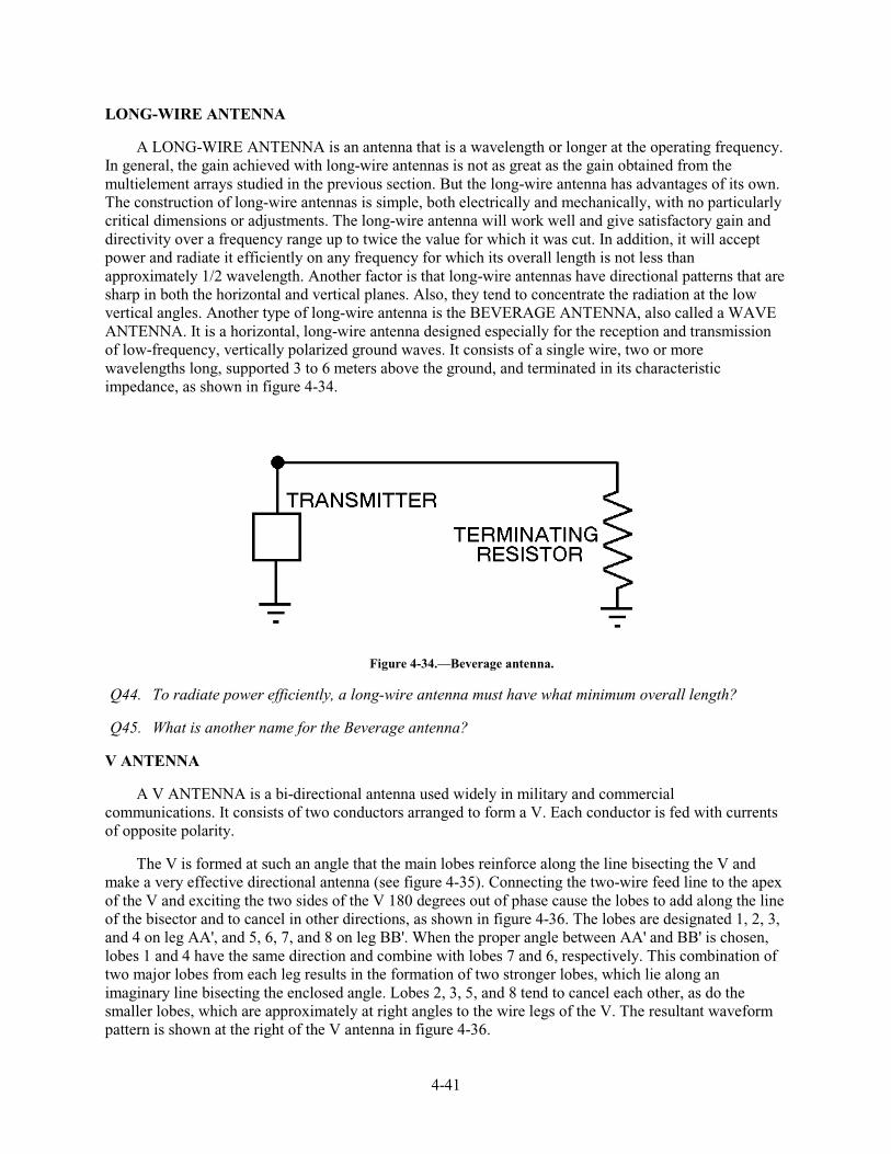
4-41
LONG-WIRE ANTENNA
A LONG-WIRE ANTENNA is an antenna that is a wavelength or longer at the operating frequency. In general, the gain achieved with long-wire antennas is not as great as the gain obtained from the multielement arrays studied in the previous section. But the long-wire antenna has advantages of its own. The construction of long-wire antennas is simple, both electrically and mechanically, with no particularly critical dimensions or adjustments. The long-wire antenna will work well and give satisfactory gain and directivity over a frequency range up to twice the value for which it was cut. In addition, it will accept power and radiate it efficiently on any frequency for which its overall length is not less than approximately 1/2 wavelength. Another factor is that long-wire antennas have directional patterns that are sharp in both the horizontal and vertical planes. Also, they tend to concentrate the radiation at the low vertical angles. Another type of long-wire antenna is the BEVERAGE ANTENNA, also called a WAVE ANTENNA. It is a horizontal, long-wire antenna designed especially for the reception and transmission of low-frequency, vertically polarized ground waves. It consists of a single wire, two or more wavelengths long, supported 3 to 6 meters above the ground, and terminated in its characteristic impedance, as shown in figure 4-34.
Figure 4-34.—Beverage antenna.
Q44. To radiate power efficiently, a long-wire antenna must have what minimum overall length?
Q45. What is another name for the Beverage antenna?
V ANTENNA
A V ANTENNA is a bi-directional antenna used widely in military and commercial communications. It consists of two conductors arranged to form a V. Each conductor is fed with currents of opposite polarity.
The V is formed at such an angle that the main lobes reinforce along the line bisecting the V and make a very effective directional antenna (see figure 4-35). Connecting the two-wire feed line to the apex of the V and exciting the two sides of the V 180 degrees out of phase cause the lobes to add along the line of the bisector and to cancel in other directions, as shown in figure 4-36. The lobes are designated 1, 2, 3, and 4 on leg AA', and 5, 6, 7, and 8 on leg BB'. When the proper angle between AA' and BB' is chosen, lobes 1 and 4 have the same direction and combine with lobes 7 and 6, respectively. This combination of two major lobes from each leg results in the formation of two stronger lobes, which lie along an imaginary line bisecting the enclosed angle. Lobes 2, 3, 5, and 8 tend to cancel each other, as do the smaller lobes, which are approximately at right angles to the wire legs of the V. The resultant waveform pattern is shown at the right of the V antenna in figure 4-36.
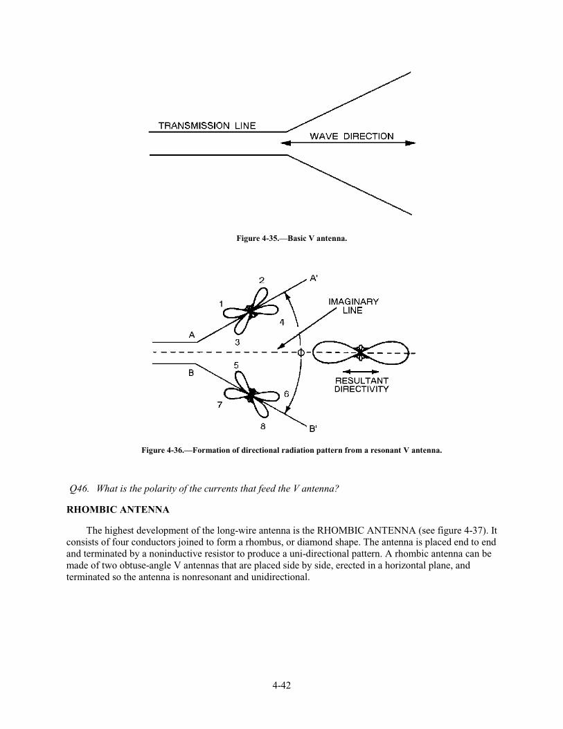
4-42
Figure 4-35.—Basic V antenna.
Figure 4-36.—Formation of directional radiation pattern from a resonant V antenna.
Q46. What is the polarity of the currents that feed the V antenna?
RHOMBIC ANTENNA
The highest development of the long-wire antenna is the RHOMBIC ANTENNA (see figure 4-37). It consists of four conductors joined to form a rhombus, or diamond shape. The antenna is placed end to end and terminated by a noninductive resistor to produce a uni-directional pattern. A rhombic antenna can be made of two obtuse-angle V antennas that are placed side by side, erected in a horizontal plane, and terminated so the antenna is nonresonant and unidirectional.
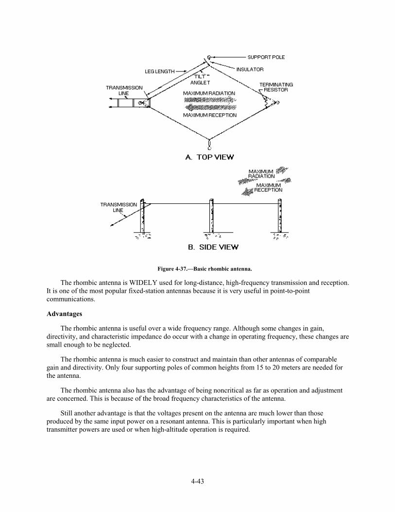
4-43
Figure 4-37.—Basic rhombic antenna.
The rhombic antenna is WIDELY used for long-distance, high-frequency transmission and reception. It is one of the most popular fixed-station antennas because it is very useful in point-to-point communications.
Advantages
The rhombic antenna is useful over a wide frequency range. Although some changes in gain, directivity, and characteristic impedance do occur with a change in operating frequency, these changes are small enough to be neglected.
The rhombic antenna is much easier to construct and maintain than other antennas of comparable gain and directivity. Only four supporting poles of common heights from 15 to 20 meters are needed for the antenna.
The rhombic antenna also has the advantage of being noncritical as far as operation and adjustment are concerned. This is because of the broad frequency characteristics of the antenna.
Still another advantage is that the voltages present on the antenna are much lower than those produced by the same input power on a resonant antenna. This is particularly important when high transmitter powers are used or when high-altitude operation is required.
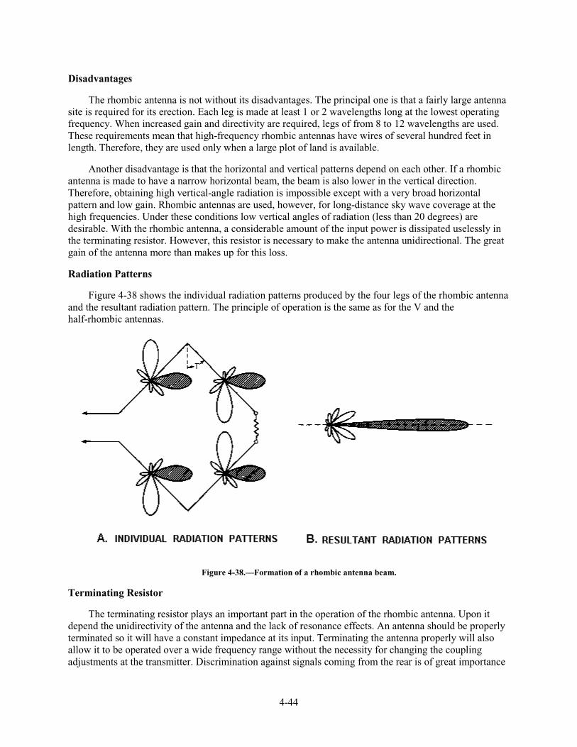
4-44
Disadvantages
The rhombic antenna is not without its disadvantages. The principal one is that a fairly large antenna site is required for its erection. Each leg is made at least 1 or 2 wavelengths long at the lowest operating frequency. When increased gain and directivity are required, legs of from 8 to 12 wavelengths are used. These requirements mean that high-frequency rhombic antennas have wires of several hundred feet in length. Therefore, they are used only when a large plot of land is available.
Another disadvantage is that the horizontal and vertical patterns depend on each other. If a rhombic antenna is made to have a narrow horizontal beam, the beam is also lower in the vertical direction. Therefore, obtaining high vertical-angle radiation is impossible except with a very broad horizontal pattern and low gain. Rhombic antennas are used, however, for long-distance sky wave coverage at the high frequencies. Under these conditions low vertical angles of radiation (less than 20 degrees) are desirable. With the rhombic antenna, a considerable amount of the input power is dissipated uselessly in the terminating resistor. However, this resistor is necessary to make the antenna unidirectional. The great gain of the antenna more than makes up for this loss.
Radiation Patterns
Figure 4-38 shows the individual radiation patterns produced by the four legs of the rhombic antenna and the resultant radiation pattern. The principle of operation is the same as for the V and the half-rhombic antennas.
Figure 4-38.—Formation of a rhombic antenna beam.
Terminating Resistor
The terminating resistor plays an important part in the operation of the rhombic antenna. Upon it depend the unidirectivity of the antenna and the lack of resonance effects. An antenna should be properly terminated so it will have a constant impedance at its input. Terminating the antenna properly will also allow it to be operated over a wide frequency range without the necessity for changing the coupling adjustments at the transmitter. Discrimination against signals coming from the rear is of great importance
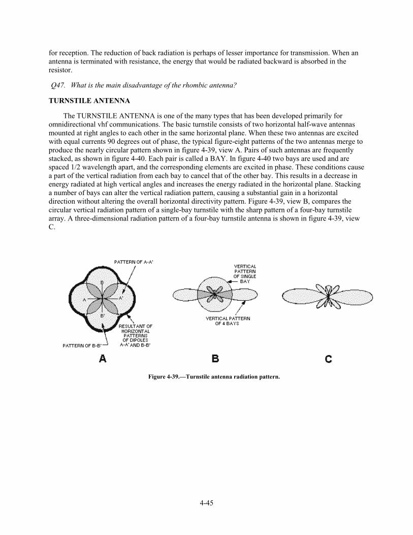
4-45
for reception. The reduction of back radiation is perhaps of lesser importance for transmission. When an antenna is terminated with resistance, the energy that would be radiated backward is absorbed in the resistor.
Q47. What is the main disadvantage of the rhombic antenna?
TURNSTILE ANTENNA
The TURNSTILE ANTENNA is one of the many types that has been developed primarily for omnidirectional vhf communications. The basic turnstile consists of two horizontal half-wave antennas mounted at right angles to each other in the same horizontal plane. When these two antennas are excited with equal currents 90 degrees out of phase, the typical figure-eight patterns of the two antennas merge to produce the nearly circular pattern shown in figure 4-39, view A. Pairs of such antennas are frequently stacked, as shown in figure 4-40. Each pair is called a BAY. In figure 4-40 two bays are used and are spaced 1/2 wavelength apart, and the corresponding elements are excited in phase. These conditions cause a part of the vertical radiation from each bay to cancel that of the other bay. This results in a decrease in energy radiated at high vertical angles and increases the energy radiated in the horizontal plane. Stacking a number of bays can alter the vertical radiation pattern, causing a substantial gain in a horizontal direction without altering the overall horizontal directivity pattern. Figure 4-39, view B, compares the circular vertical radiation pattern of a single-bay turnstile with the sharp pattern of a four-bay turnstile array. A three-dimensional radiation pattern of a four-bay turnstile antenna is shown in figure 4-39, view C.
Figure 4-39.—Turnstile antenna radiation pattern.
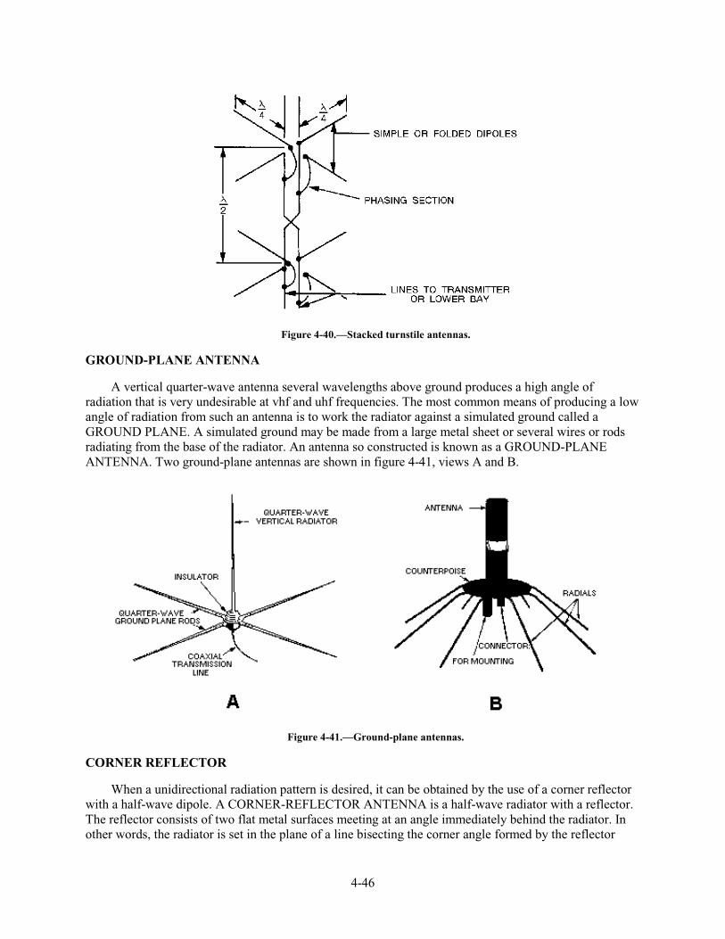
4-46
Figure 4-40.—Stacked turnstile antennas.
GROUND-PLANE ANTENNA
A vertical quarter-wave antenna several wavelengths above ground produces a high angle of radiation that is very undesirable at vhf and uhf frequencies. The most common means of producing a low angle of radiation from such an antenna is to work the radiator against a simulated ground called a GROUND PLANE. A simulated ground may be made from a large metal sheet or several wires or rods radiating from the base of the radiator. An antenna so constructed is known as a GROUND-PLANE ANTENNA. Two ground-plane antennas are shown in figure 4-41, views A and B.
Figure 4-41.—Ground-plane antennas.
CORNER REFLECTOR
When a unidirectional radiation pattern is desired, it can be obtained by the use of a corner reflector with a half-wave dipole. A CORNER-REFLECTOR ANTENNA is a half-wave radiator with a reflector. The reflector consists of two flat metal surfaces meeting at an angle immediately behind the radiator. In other words, the radiator is set in the plane of a line bisecting the corner angle formed by the reflector
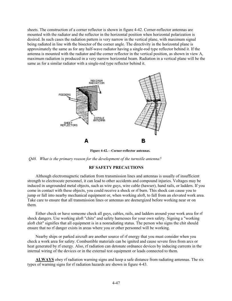
4-47
sheets. The construction of a corner reflector is shown in figure 4-42. Corner-reflector antennas are mounted with the radiator and the reflector in the horizontal position when horizontal polarization is desired. In such cases the radiation pattern is very narrow in the vertical plane, with maximum signal being radiated in line with the bisector of the corner angle. The directivity in the horizontal plane is approximately the same as for any half-wave radiator having a single-rod type reflector behind it. If the antenna is mounted with the radiator and the corner reflector in the vertical position, as shown in view A, maximum radiation is produced in a very narrow horizontal beam. Radiation in a vertical plane will be the same as for a similar radiator with a single-rod type reflector behind it.
Figure 4-42.—Corner-reflector antennas.
Q48. What is the primary reason for the development of the turnstile antenna?
RF SAFETY PRECAUTIONS
Although electromagnetic radiation from transmission lines and antennas is usually of insufficient strength to electrocute personnel, it can lead to other accidents and compound injuries. Voltages may be induced in ungrounded metal objects, such as wire guys, wire cable (hawser), hand rails, or ladders. If you come in contact with these objects, you could receive a shock or rf burn. This shock can cause you to jump or fall into nearby mechanical equipment or, when working aloft, to fall from an elevated work area. Take care to ensure that all transmission lines or antennas are deenergized before working near or on them.
Either check or have someone check all guys, cables, rails, and ladders around your work area for rf shock dangers. Use working aloft "chits" and safety harnesses for your own safety. Signing a "working aloft chit" signifies that all equipment is in a nonradiating status. The person who signs the chit should ensure that no rf danger exists in areas where you or other personnel will be working.
Nearby ships or parked aircraft are another source of rf energy that you must consider when you check a work area for safety. Combustible materials can be ignited and cause severe fires from arcs or heat generated by rf energy. Also, rf radiation can detonate ordnance devices by inducing currents in the internal wiring of the devices or in the external test equipment or leads connected to them.
ALWAYS obey rf radiation warning signs and keep a safe distance from radiating antennas. The six types of warning signs for rf radiation hazards are shown in figure 4-43.
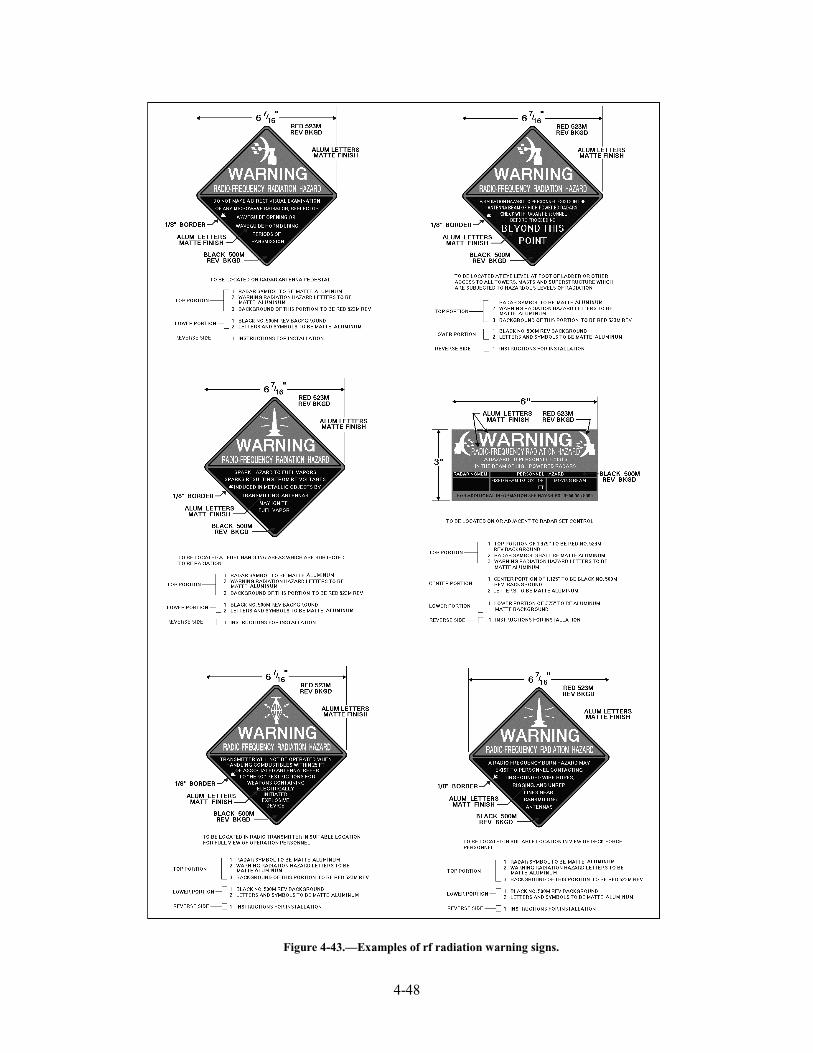
4-48
Figure 4-43.—Examples of rf radiation warning signs.
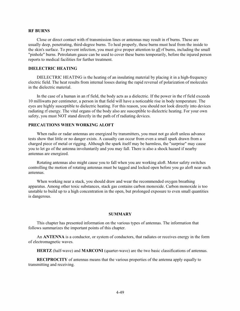
4-49
RF BURNS
Close or direct contact with rf transmission lines or antennas may result in rf burns. These are usually deep, penetrating, third-degree burns. To heal properly, these burns must heal from the inside to the skin's surface. To prevent infection, you must give proper attention to all rf burns, including the small "pinhole" burns. Petrolatum gauze can be used to cover these burns temporarily, before the injured person reports to medical facilities for further treatment.
DIELECTRIC HEATING
DIELECTRIC HEATING is the heating of an insulating material by placing it in a high-frequency electric field. The heat results from internal losses during the rapid reversal of polarization of molecules in the dielectric material.
In the case of a human in an rf field, the body acts as a dielectric. If the power in the rf field exceeds 10 milliwatts per centimeter, a person in that field will have a noticeable rise in body temperature. The eyes are highly susceptible to dielectric heating. For this reason, you should not look directly into devices radiating rf energy. The vital organs of the body also are susceptible to dielectric heating. For your own safety, you must NOT stand directly in the path of rf radiating devices.
PRECAUTIONS WHEN WORKING ALOFT
When radio or radar antennas are energized by transmitters, you must not go aloft unless advance tests show that little or no danger exists. A casualty can occur from even a small spark drawn from a charged piece of metal or rigging. Although the spark itself may be harmless, the "surprise" may cause you to let go of the antenna involuntarily and you may fall. There is also a shock hazard if nearby antennas are energized.
Rotating antennas also might cause you to fall when you are working aloft. Motor safety switches controlling the motion of rotating antennas must be tagged and locked open before you go aloft near such antennas.
When working near a stack, you should draw and wear the recommended oxygen breathing apparatus. Among other toxic substances, stack gas contains carbon monoxide. Carbon monoxide is too unstable to build up to a high concentration in the open, but prolonged exposure to even small quantities is dangerous.
SUMMARY
This chapter has presented information on the various types of antennas. The information that follows summarizes the important points of this chapter.
An ANTENNA is a conductor, or system of conductors, that radiates or receives energy in the form of electromagnetic waves.
HERTZ (half-wave) and MARCONI (quarter-wave) are the two basic classifications of antennas.
RECIPROCITY of antennas means that the various properties of the antenna apply equally to transmitting and receiving.
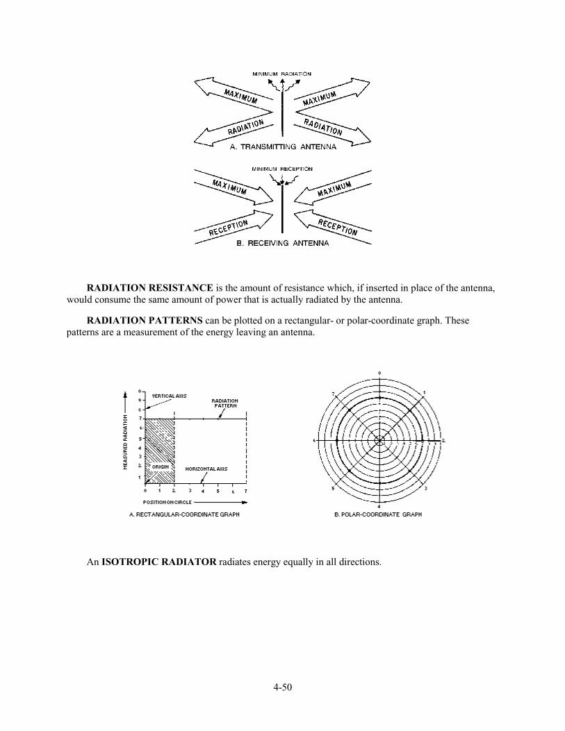
4-50
RADIATION RESISTANCE is the amount of resistance which, if inserted in place of the antenna, would consume the same amount of power that is actually radiated by the antenna.
RADIATION PATTERNS can be plotted on a rectangular- or polar-coordinate graph. These patterns are a measurement of the energy leaving an antenna.
An ISOTROPIC RADIATOR radiates energy equally in all directions.
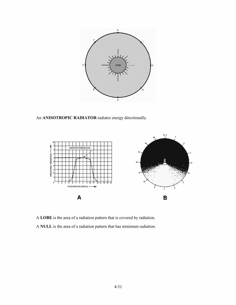
4-51
An ANISOTROPIC RADIATOR radiates energy directionally.
A LOBE is the area of a radiation pattern that is covered by radiation.
A NULL is the area of a radiation pattern that has minimum radiation.
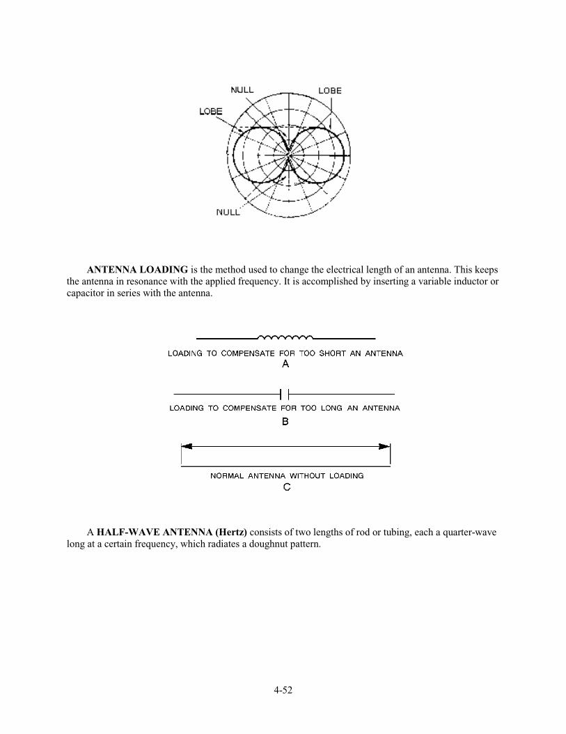
4-52
ANTENNA LOADING is the method used to change the electrical length of an antenna. This keeps the antenna in resonance with the applied frequency. It is accomplished by inserting a variable inductor or capacitor in series with the antenna.
A HALF-WAVE ANTENNA (Hertz) consists of two lengths of rod or tubing, each a quarter-wave long at a certain frequency, which radiates a doughnut pattern.
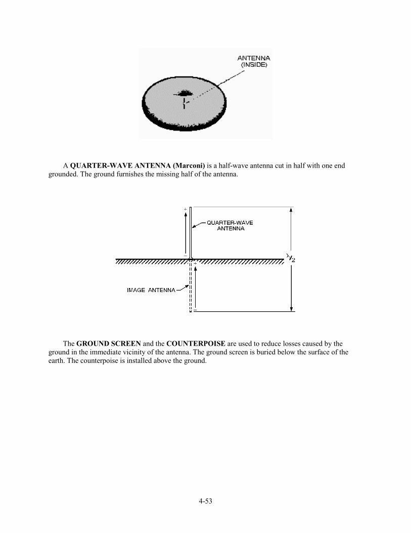
4-53
A QUARTER-WAVE ANTENNA (Marconi) is a half-wave antenna cut in half with one end grounded. The ground furnishes the missing half of the antenna.
The GROUND SCREEN and the COUNTERPOISE are used to reduce losses caused by the ground in the immediate vicinity of the antenna. The ground screen is buried below the surface of the earth. The counterpoise is installed above the ground.

4-54
The FOLDED DIPOLE consists of a dipole radiator, which is connected in parallel at its ends to a half-wave radiator.
AN ARRAY is a combination of half-wave elements operating together as a single antenna. It provides more gain and greater directivity than single element antennas.
A DRIVEN ARRAY derives its power directly from the source.
A PARASITIC ARRAY derives its power by coupling the energy from other elements of the antenna.
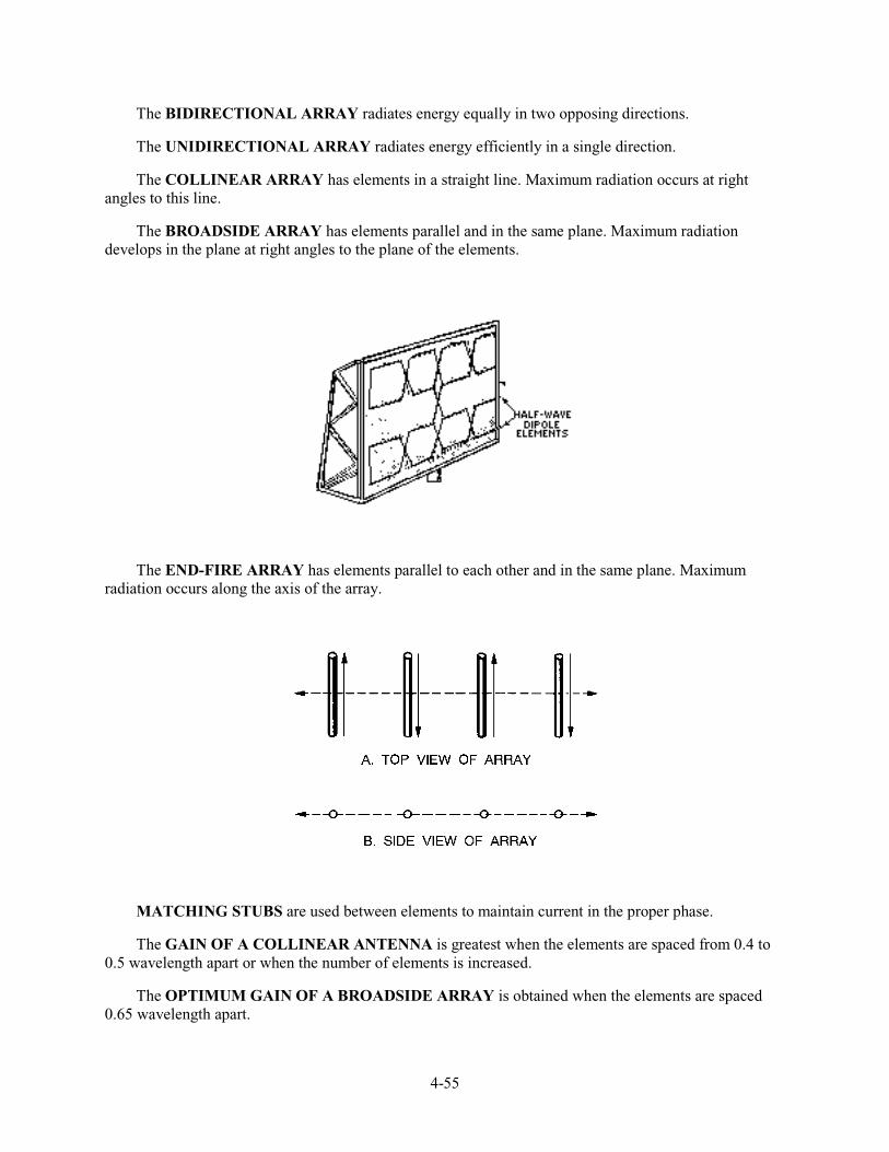
4-55
The BIDIRECTIONAL ARRAY radiates energy equally in two opposing directions.
The UNIDIRECTIONAL ARRAY radiates energy efficiently in a single direction.
The COLLINEAR ARRAY has elements in a straight line. Maximum radiation occurs at right angles to this line.
The BROADSIDE ARRAY has elements parallel and in the same plane. Maximum radiation develops in the plane at right angles to the plane of the elements.
The END-FIRE ARRAY has elements parallel to each other and in the same plane. Maximum radiation occurs along the axis of the array.
MATCHING STUBS are used between elements to maintain current in the proper phase.
The GAIN OF A COLLINEAR ANTENNA is greatest when the elements are spaced from 0.4 to 0.5 wavelength apart or when the number of elements is increased.
The OPTIMUM GAIN OF A BROADSIDE ARRAY is obtained when the elements are spaced 0.65 wavelength apart.

4-56
A PARASITIC ARRAY consists of one or more parasitic elements with a driven element. The amount of power gain and directivity depends on the lengths of the parasitic elements and the spacing between them.
MULTIELEMENT ARRAYS, such as the YAGI, have a narrow frequency response as well as a narrow beamwidth.
A LONG-WIRE ANTENNA is an antenna that is a wavelength or more long at the operating frequency. These antennas have directive patterns that are sharp in both the horizontal and vertical planes.
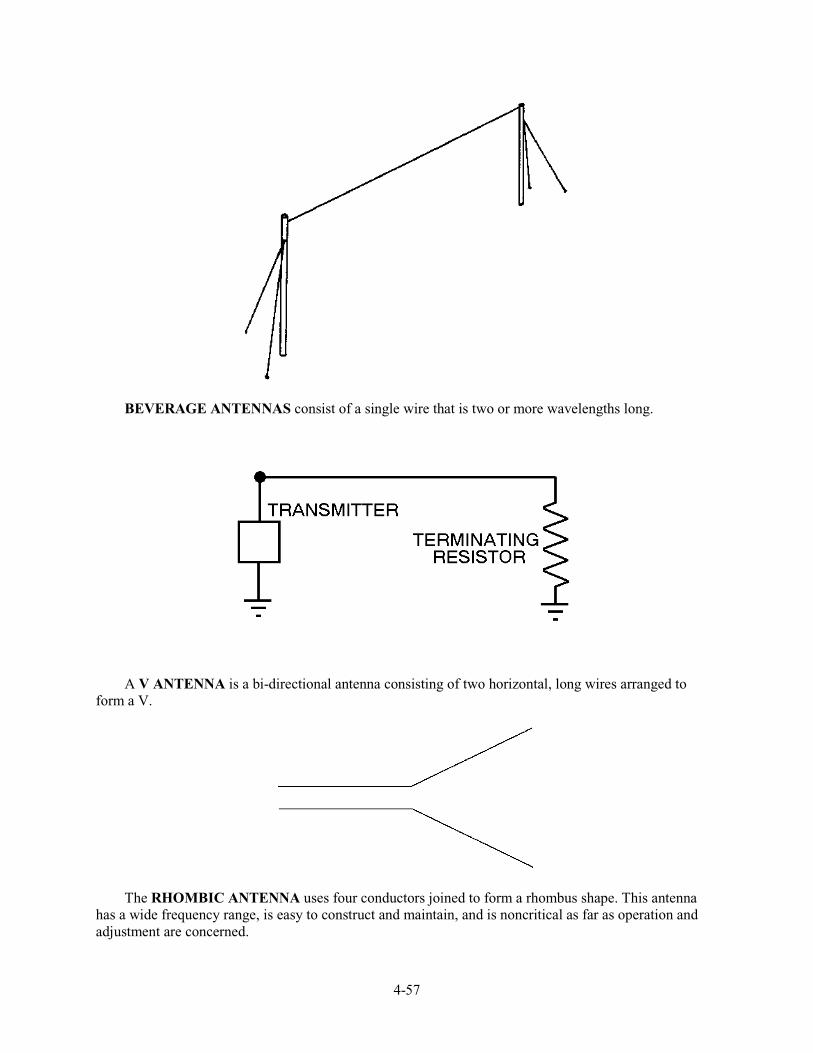
4-57
BEVERAGE ANTENNAS consist of a single wire that is two or more wavelengths long.
A V ANTENNA is a bi-directional antenna consisting of two horizontal, long wires arranged to form a V.
The RHOMBIC ANTENNA uses four conductors joined to form a rhombus shape. This antenna has a wide frequency range, is easy to construct and maintain, and is noncritical as far as operation and adjustment are concerned.
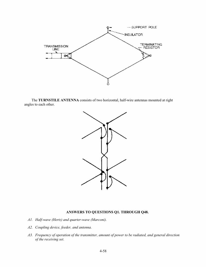
4-58
The TURNSTILE ANTENNA consists of two horizontal, half-wire antennas mounted at right angles to each other.
ANSWERS TO QUESTIONS Q1. THROUGH Q48.
A1. Half-wave (Hertz) and quarter-wave (Marconi).
A2. Coupling device, feeder, and antenna.
A3. Frequency of operation of the transmitter, amount of power to be radiated, and general direction of the receiving set.
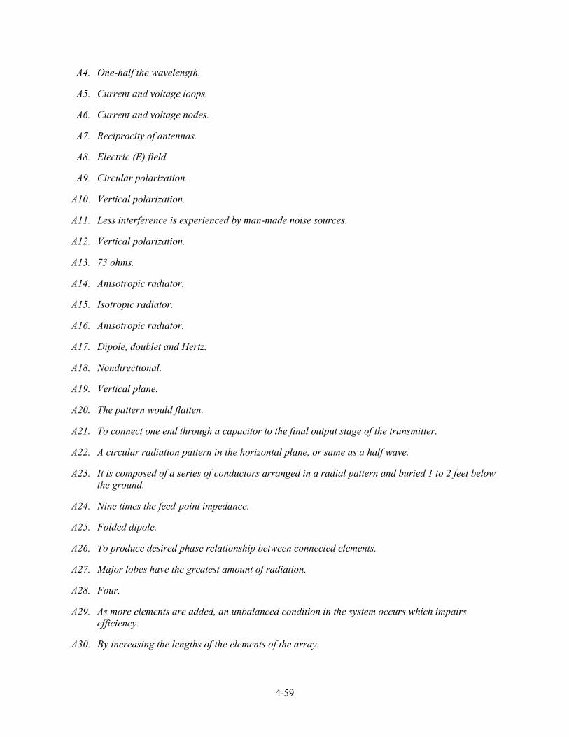
4-59
A4. One-half the wavelength.
A5. Current and voltage loops.
A6. Current and voltage nodes.
A7. Reciprocity of antennas.
A8. Electric (E) field.
A9. Circular polarization.
A10. Vertical polarization.
A11. Less interference is experienced by man-made noise sources.
A12. Vertical polarization.
A13. 73 ohms.
A14. Anisotropic radiator.
A15. Isotropic radiator.
A16. Anisotropic radiator.
A17. Dipole, doublet and Hertz.
A18. Nondirectional.
A19. Vertical plane.
A20. The pattern would flatten.
A21. To connect one end through a capacitor to the final output stage of the transmitter.
A22. A circular radiation pattern in the horizontal plane, or same as a half wave.
A23. It is composed of a series of conductors arranged in a radial pattern and buried 1 to 2 feet below the ground.
A24. Nine times the feed-point impedance.
A25. Folded dipole.
A26. To produce desired phase relationship between connected elements.
A27. Major lobes have the greatest amount of radiation.
A28. Four.
A29. As more elements are added, an unbalanced condition in the system occurs which impairs efficiency.
A30. By increasing the lengths of the elements of the array.
4-60
A31. Directivity increases.
A32. Lower radiation resistance.
A33. Parallel and in the same plane.
A34. They sharpen.
A35. Extremely low radiation resistance, confined to one frequency, and affected by atmospheric conditions.
A36. Along the major axis
A37. Symmetrically.
A38. Length of the parasitic element (tuning) and spacing between the parasitic and driven elements.
A39. Increased gain and directivity.
A40. Rotary array.
A41. Their adjustment is critical and they do not operate over a wide frequency range.
A42. Increased gain.
A43. Multielement parasitic array.
A44. One-half wavelength.
A45. Wave antenna.
A46. Opposite.
A47. It requires a large antenna site.
A48. For omnidirectional vhf communications.
AI-1
$33(1',;�,
GLOSSARY
ABSORPTION—(1) Absorbing light waves. Does not allow any reflection or refraction.(2) Atmospheric absorption of rf energy with no reflection or refraction (adversely affects longdistance communications).
ACOUSTICS—The science of sound.
AMPLITUDE—The portion of a cycle measured from a reference line to a maximum value above (or toa maximum value below) the line.
ANGLE OF INCIDENCE—The angle between the incident wave and the normal.
ANGLE OF REFLECTION—The angle between the reflected wave and the normal.
ANGLE OF REFRACTION—The angle between the normal and the path of a wave through the secondmedium.
ANGSTROM UNIT—The unit used to define the wavelength of light waves.
ANISOTROPIC—The property of a radiator to emit strong radiation in one direction.
ANTENNA—A conductor or set of conductors used either to radiate rf energy into space or to collect rfenergy from space.
ARRAY OF ARRAYS—Same as COMBINATION ARRAY.
BAY—Part of an antenna array.
BEVERAGE ANTENNA—A horizontal, longwire antenna designed for reception and transmission oflow-frequency, vertically polarized ground waves.
BIDIRECTIONAL ARRAY—An array that radiates in opposite directions along the line of maximumradiation.
BROADSIDE ARRAY—An array in which the direction of maximum radiation is perpendicular to theplane containing the elements.
CENTER-FEED METHOD—Connecting the center of an antenna to a transmission line, which is thenconnected to the final (output) stage of the transmitter.
CHARACTERISTIC IMPEDANCE—The ratio of voltage to current at any given point on atransmission line. Represented by a value of impedance.
COAXIAL LINE—A type of transmission line that contains two concentric conductors.
COLLINEAR ARRAY—An array with all the elements in a straight line. Maximum radiation isperpendicular to the axis of the elements.
COMBINATION ARRAY—An array system that uses the characteristics of more than one array.
AI-2
COMPLEMENTARY (SECONDARY) COLORS OF LIGHT—The colors of light produced whentwo of the primaries are mixed in overlapping beams of light. The complementary colors of light aremagenta, yellow, and cyan.
COMPLEX WAVE—A wave produced by combining two or more pure tones at the same time.
COMPRESSION WAVES—Longitudinal waves that have been compressed (made more dense) as theymove away from the source.
CONDUCTANCE—The opposite of resistance in transmission lines. The minute amount of resistancethat is present in the insulator of a transmission line.
CONNECTED ARRAY—Another term for DRIVEN ARRAY.
COPPER LOSSES—The I2R loss in a conductor caused by the current flow through the resistance of theconductor.
CORNER-REFLECTOR ANTENNA—A half-wave antenna with a reflector consisting of two flatmetal surfaces meeting at an angle behind the radiator.
COUNTERPOISE—A network of wire that is connected to a quarter-wave antenna at one end andprovides the equivalent of an additional 1/4 wavelength.
COUPLING DEVICE—A coupling coil that connects the transmitter to the feeder.
CREST (TOP)—The peak of the positive alternation (maximum value above the line) of a wave.
CRITICAL ANGLE—The maximum angle at which radio waves can be transmitted and still berefracted back to earth.
CRITICAL FREQUENCY—The maximum frequency at which a radio wave can be transmittedvertically and still be refracted back to earth.
CURRENT-FEED METHOD—Same as CENTER-FEED METHOD.
CURRENT STANDING-WAVE RATIO (ISWR)—The ratio of maximum to minimum current along atransmission line.
CYCLE—One complete alternation of a sine wave that has a maximum value above and a maximumvalue below the reference line.
DAMPING—Reduction of energy by absorption.
DENSITY—(1) The compactness of a substance. (2) Mass per unit volume.
DETECTOR—The device that responds to a wave or disturbance.
DIELECTRIC HEATING—The heating of an insulating material by placing it in a high frequencyelectric field.
DIELECTRIC LOSSES—The losses resulting from the heating effect on the dielectric material betweenconductors.
DIFFRACTION—The bending of the paths of waves when the waves meet some form of obstruction.
AI-3
DIFFUSION—The scattering of reflected light waves (beams) from an object, such as white paper.
DIPOLE—A common type of half-wave antenna made from a straight piece of wire cut in half. Eachhalf operates at a quarter wavelength of the output.
DIRECTIONAL—Radiation that varies with direction.
DIRECTOR—The parasitic element of an array that reinforces energy coming from the driver towarditself.
DIRECTIVITY—The property of an array that causes more radiation to take place in certain directionsthan in others.
DISPERSION—The refraction of light waves that causes the different frequencies to bend at slightlydifferent angles.
DISTRIBUTED CONSTANTS—The constants of inductance, capacitance, and resistance in atransmission line. The constants are spread along the entire length of the line and cannot bedistinguished separately.
DOPPLER EFFECT—The apparent change in frequency or pitch when a sound source moves eithertoward or away from a listener.
DOUBLET—Another name for the dipole antenna.
DRIVEN ARRAY—An array in which all of the elements are driven.
DRIVEN ELEMENT—An element of an antenna (transmitting or receiving) that is connected directlyto the transmission line.
ECHO—The reflection of the original sound wave as it bounces off a distant surface.
ELASTICITY—The ability of a substance to return to its original state.
ELECTROMAGNETIC FIELD—The combination of an electric (E) field and a magnetic (H) field.
ELECTROMAGNETIC INTERFERENCE—Man-made or natural interference that degrades thequality of reception of radio waves.
ELECTROMAGNETIC RADIATION—The radiation of radio waves into space.
ELECTRIC (E) FIELD—The field produced as a result of a voltage charge on a conductor or antenna.
ELEMENT—A part of an antenna that can be either an active radiator or a parasitic radiator.
END-FEED METHOD—Connecting one end of an antenna through a capacitor to the final output stageof a transmitter.
END-FIRE ARRAY—An array in which the direction of radiation is parallel to the axis of the array.
FADING—Variations in signal strength by atmospheric conditions.
FEEDER—A transmission line that carries energy to the antenna.
AI-4
FLAT LINE—A transmission line that has no standing waves. This line requires no special tuningdevice to transfer maximum power.
FLEXIBLE COAXIAL LINE—A coaxial line made with a flexible inner conductor insulated from theouter conductor by a solid, continuous insulating material.
FOLDED DIPOLE—An ordinary half-wave antenna (dipole) that has one or more additional conductorsconnected across the ends parallel to each other.
FOUR-ELEMENT ARRAY—An array with three parasitic elements and one driven element.
FREE-SPACE LOSS—The loss of energy of a radio wave because of the spreading of the wavefront asit travels from the transmitter.
FREQUENCY—The number of cycles that occur in one second. Usually expressed in hertz.
FREQUENCY DIVERSITY—Transmitting (and receiving) of radio waves on two different frequenciessimultaneously.
FRONT-TO-BACK RATIO—The ratio of the energy radiated in the principal direction to the energyradiated in the opposite direction.
FUNDAMENTAL FREQUENCY—The basic frequency or first harmonic frequency.
GAIN—The ratio between the amount of energy propagated from an antenna that is directional to theenergy from the same antenna that would be propagated if the antenna were not directional.
GENERATOR END—See INPUT END.
GROUND PLANE—The portion of a groundplane antenna that acts as ground.
GROUND-PLANE ANTENNA—A type of antenna that uses a ground plane as a simulated ground toproduce low-angle radiation.
GROUND REFLECTION LOSS—The loss of rf energy each time a radio wave is reflected from theEarth's surface.
GROUND SCREEN—A series of conductors buried below the surface of the earth and arranged in aradial pattern. Used to reduce losses in the ground.
GROUND WAVES—Radio waves that travel near the surface of the Earth.
HALF-WAVE DIPOLE ANTENNA—An antenna consisting of two rods (1/4 wavelength each) in astraight line, that radiates electromagnetic energy.
HARMONIC—A frequency that is a whole number multiple of a smaller base frequency.
HERTZ ANTENNA—A half-wave antenna installed some distance above ground and positioned eithervertically or horizontally.
HORIZONTAL AXIS—On a graph, the straight line axis plotted from left to right.
HORIZONTAL PATTERN—The part of a radiation pattern that is radiated in all directions along thehorizontal plane.
AI-5
HORIZONTALLY POLARIZED—Waves that are radiated with their E field component parallel to theEarth's surface.
INCIDENT WAVE—(1) The wave that strikes the surface of a medium. (2) The wave that travels fromthe sending end to the receiving end of a transmission line.
INDUCTION FIELD—The electromagnetic field produced about an antenna when current and voltageare present on the same antenna.
INDUCTION LOSSES—The losses that occur when the electromagnetic field around a conductor cutsthrough a nearby metallic object and induces a current into that object.
INFRASONIC (SUBSONIC)—Sounds below 15 hertz.
INPUT END—The end of a two-wire transmission line that is connected to a source.
INPUT IMPEDANCE—The impedance presented to the transmitter by the transmission line and itsload.
INTENSITY (OF SOUND)—The measurement of the amplitude of sound energy. Sometimesmistakenly called loudness.
INTERCEPT—The point where two lines drawn on a graph cross each other.
INTERFERENCE—Any disturbance that produces an undesirable response or degrades a wave.
IONOSPHERE—The most important region of the atmosphere extending from 31 miles to 250 milesabove the earth. Contains four cloud-like layers that affect radio waves.
IONOSPHERIC STORMS—Disturbances in the earth's magnetic field that make communicationspractical only at lower frequencies.
IONIZATION—The process of upsetting electrical neutrality.
ISOTROPIC RADIATION—The radiation of energy equally in all directions.
LEAKAGE CURRENT—The small amount of current that flows between the conductors of atransmission line through the dielectric.
LIGHT RAYS—Straight lines that represent light waves emitting from a source.
LOAD END—See OUTPUT END.
LOADING—See LUMPED-IMPEDANCE TUNING.
LOBE—An area of a radiation pattern plotted on a polar-coordinate graph that represents maximumradiation.
LONG-WIRE ANTENNA—An antenna that is a wavelength or more long at its operating frequency.
LONGITUDINAL WAVES—Waves in which the disturbance (back and forth motion) takes place inthe direction of propagation. Sometimes called compression waves.
LOOP—The curves of a standing wave or antenna that represent amplitude of current or voltage.
AI-6
LOWEST USABLE FREQUENCY—The minimum operating frequency that can be used forcommunications between two points.
LUMPED CONSTANTS—The properties of inductance, capacitance, and resistance in a transmissionline.
LUMPED-IMPEDANCE TUNING—The insertion of an inductor or capacitor in series with an antennato lengthen or shorten the antenna electrically.
MAGNETIC (H) FIELD—The field produced when current flows through a conductor or antenna.
MAJOR LOBE—The lobe in which the greatest amount of radiation occurs.
MARCONI ANTENNA—A quarter-wave antenna oriented perpendicular to the earth and operated withone end grounded.
MAXIMUM USABLE FREQUENCY— Maximum frequency that can be used for communicationsbetween two locations for a given time of day and a given angle of incidence.
MEDIUM—The substance through which a wave travels from one point to the next. Air, water, wood,etc., are examples of a medium.
MINOR LOBE—The lobe in which the radiation intensity is less than a major lobe.
MULTIELEMENT ARRAY—An array consisting of one or more arrays and classified as to directivity.
MULTIELEMENT PARASITIC ARRAY— An array that contains two or more parasitic elements anda driven element.
MULTIPATH—The multiple paths a radio wave may follow between transmitter and receiver.
NATURAL HORIZON—The line-of-sight horizon.
NEGATIVE ALTERNATION—The portion of a sine wave below the reference line.
NODE—The fixed minimum points of voltage or current on a standing wave or antenna.
NOISE (OF SOUND)—An unwanted disturbance caused by spurious waves that originate from man-made or natural sources.
NONDIRECTIONAL—See OMNIDIRECTIONAL.
NONLUMINOUS BODIES—Objects that either reflect or diffuse light that falls upon them.
NONRESONANT LINE—A transmission line that has no standing waves of current or voltage.
NORMAL—The imaginary line perpendicular to the point at which the incident wave strikes thereflecting surface. Also called the perpendicular.
NULL—On a polar-coordinate graph, the area that represents minimum or 0 radiation.
OMNIDIRECTIONAL—Transmitting in all directions.
OPAQUE—A type of substance that does not transmit any light rays.
OPEN-ENDED LINE—A transmission line that has an infinitely large terminating impedance.
AI-7
OPTIMUM WORKING FREQUENCY—The most practical operating frequency that can be used withthe least amount of problems; roughly 85 percent of the maximum usable frequency.
ORIGIN—The point on a graph where the vertical and horizontal axes cross each other.
OUTPUT END—The end of a transmission line that is opposite the source.
OUTPUT IMPEDANCE —The impedance presented to the load by the transmission line and its source.
PARALLEL RESONANT CIRCUIT—A circuit that acts as a high impedance at resonance.
PARALLEL-WIRE—A type of transmission line consisting of two parallel wires.
PARASITIC ARRAY—An array that has one or more parasitic elements.
PARASITIC ELEMENT—The passive element of an antenna array that is connected to neither thetransmission line nor the driven element.
PERIOD—The amount of time required for completion of one full cycle.
PITCH—A term used to describe the frequency of a sound heard by the human ear.
PLANE OF POLARIZATION—The plane (vertical or horizontal) with respect to the earth in which theE field propagates.
POINT OF ZERO DISPLACEMENT—See REFERENCE LINE.
POLAR-COORDINATE GRAPH—A graph whose axes consist of a series of circles with a commoncenter and a rotating radius extending from the center of the concentric circles.
POSITIVE ALTERNATION—The portion of a sine wave above the reference line.
POWER LOSS—The heat loss in a conductor as current flows through it.
POWER STANDING-WAVE RATIO (PSWR)—The ratio of the square of the maximum andminimum voltages of a transmission line.
PRIMARY COLORS (OF LIGHT)—The three primary colors of light (red, green, and blue), fromwhich all other colors may be derived.
PRISM—A triangular-shaped glass that refracts and disperses light waves into component wavelengths.
PROPAGATION—Waves traveling through a medium.
QUALITY (OF SOUND)—The factor that distinguishes tones of pitch and loudness.
QUARTER-WAVE ANTENNA—Same as the Marconi antenna.
RADIATION FIELD—The electromagnetic field that detaches itself from an antenna and travelsthrough space.
RADIATION LOSSES—The losses that occur when magnetic lines of force about a conductor areprojected into space as radiation and are not returned to the conductor as the cycle alternates.
RADIATION PATTERN—A plot of the radiated energy from an antenna.
AI-8
RADIATION RESISTANCE—The resistance, which if inserted in place of an antenna, would consumethe same amount of power as that radiated by the antenna.
RADIO FREQUENCIES—Electromagnetic frequencies that fall between 3 kilohertz and 300 gigahertzand are used for radio communications.
RADIO HORIZON—The boundary beyond the natural horizon in which radio waves cannot bepropagated over the earth's surface.
RADIO WAVE—(1) A form of radiant energy that can neither be seen nor felt. (2) An electromagneticwave generated by a transmitter.
RAREFIED WAVE—A longitudinal wave that has been expanded or rarefied (made less dense) as itmoves away from the source.
RECEIVER—The object that responds to a wave or disturbance. Same as detector.
RECEIVING ANTENNA—The device used to pick up an rf signal from space.
RECEIVING END—See OUTPUT END.
RECIPROCITY—The property of interchangeability of the same antenna for transmitting and receiving.
RECTANGULAR-COORDINATE GRAPH—A graph in which straight-line axes (horizontal andvertical) are perpendicular.
REFERENCE LINE—The position a particle of matter would occupy if it were not disturbed by wavemotion.
REFLECTED WAVE—(1) The wave that reflects back from a medium. (2) Waves traveling from theload back to the generator on a transmission line. (3) The wave moving back to the sending end of atransmission line after reflection has occurred.
REFLECTION WAVES—Waves that are neither transmitted nor absorbed, but are reflected from thesurface of the medium they encounter.
REFLECTOR—The parasitic element of an array that causes maximum energy radiation in a directiontoward the driven element.
REFRACTION—The changing of direction as a wave leaves one medium and enters another medium ofa different density.
RERADIATION—The reception and retransmission of radio waves caused by turbulence in thetroposphere.
RESONANCE—The condition produced when the frequency of vibrations are the same as the naturalfrequency (of a cavity). The vibrations reinforce each other.
RESONANT LINE—A transmission line that has standing waves of current and voltage.
REST POSITION—See REFERENCE LINE.
REVERBERATION—The multiple reflections of sound waves.
AI-9
RHOMBIC ANTENNA—A diamond-shaped antenna used widely for long-distance, high-frequencytransmission and reception.
RIGID COAXIAL LINE—A coxial line consisting of a central, insulated wire (inner conductor)mounted inside a tubular outer conductor.
SCATTER ANGLE—The angle at which the receiving antenna must be aimed to capture the scatteredenergy of tropospheric scatter.
SELF-INDUCTION—The phenomenon caused by the expanding and collapsing fields of an electronwhich encircles other electrons and retards the movement of the encircled electrons.
SELF-LUMINOUS BODIES—Objects that produce their own light.
SENDING END—See INPUT END.
SERIES RESONANT CIRCUIT—A circuit that acts as a low impedance at resonance.
SHIELDED PAIR—A line consisting of parallel conductors separated from each other and surroundedby a solid dielectric.
SHORT-CIRCUITED LINE—A transmission line that has a terminating impedance equal to 0.
SINK—See OUTPUT END.
SKIN EFFECT—The flow of ac current near the surface of a conductor at rf frequencies.
SKIP DISTANCE—The distance from a transmitter to the point where the sky wave is first returned toearth.
SKIP ZONE—A zone of silence between the point where the ground wave becomes too weak forreception and the point where the sky wave is first returned to earth.
SKY WAVES—Radio waves reflected back to earth from the ionosphere.
SONIC—Pertaining to sounds capable of being heard by the human ear.
SOURCE—(1) The object that produces waves or disturbance. (2) The name given to the end of a two-wire transmission line that is connected to a source.
SPACE DIVERSITY—Reception of radio waves by two or more antennas spaced some distance apart.
SPACE WAVE—A radio wave that travels directly from the transmitter to the receiver and remains inthe troposphere.
SPECTRUM—(1) The entire range of electromagnetic waves. (2) VISIBLE. The range ofelectromagnetic waves that stimulate the sense of sight. (3) ELECTROMAGNETIC. The entirerange of electromagnetic waves arranged in order of their frequencies.
SPORADIC E LAYER—Irregular cloud-like patches of unusually high ionization. Often forms atheights near the normal E layer.
SPREADER—Insulator used with transmission lines and antennas to keep the parallel wires separated.
AI-10
STANDING WAVE—The distribution of voltage and current formed by the incident and reflectedwaves which have minimum and maximum points on a resultant wave that appears to stand still.
STANDING-WAVE RATIO (SWR)—The ratio of the maximum (voltage, current) to the minimum(voltage, current) of a transmission line. Measures the perfection of the termination of the line.
STRATOSPHERE—Located between the troposphere and the ionosphere. Has little effect on radiowaves.
STUB—Short section of a transmission line used to match the impedance of a transmission line to anantenna. Can also be used to produce desired phase relationships between connected elements of anantenna.
SUDDEN IONOSPHERIC DISTURBANCE—An irregular ionospheric disturbance that can totallyblank out hf radio communications.
SUPERSONIC—Speed greater than the speed of sound.
SURFACE WAVE—A radio wave that travels along the contours of the earth, thereby being highlyattenuated.
TEMPERATURE INVERSION—The condition in which warm air is formed above a layer of cool airthat is near the earth's surface.
THREE-ELEMENT ARRAY—An array with two parasitic elements (reflector and director) and adriven element.
TONES—Musical sounds.
TRANSLUCENT—A type of substance, such as frosted glass, through which some light rays can passbut through which objects cannot be seen clearly.
TRANSMISSION LINE—A device designed to guide electrical energy from one point to another.
TRANSMITTING ANTENNA—The device used to send the transmitted signal energy into space.
TRANSPARENT—A type of substance, such as glass, that transmits almost all of the light waves thatfall upon it.
TRANSMISSION MEDIUMS—The various types of lines and waveguides used as transmission lines.
TRANSMITTER END—See INPUT END.
TRANSVERSE WAVE MOTION—The up and down motion of a wave as the wave moves outward.
TROPOSPHERE—The portion of the atmosphere closest to the earth's surface, where all weatherphenomena take place.
TROPOSPHERIC SCATTER—The propagation of radio waves in the troposphere by means of scatter.
TROUGH (BOTTOM)—The peak of the negative alternation (maximum value below the line).
TUNED LINE—Another name for the resonant line. This line uses tuning devices to eliminate thereactance and to transfer maximum power from the source to the line.
AI-11
TURNSTILE ANTENNA—A type of antenna used in vhf communications that is omnidirectional andconsists of two horizontal half-wave antennas mounted at right angles to each other in the samehorizontal plane.
TWISTED PAIR—A line consisting of two insulated wires twisted together to form a flexible linewithout the use of spacers.
TWO-WIRE OPEN LINE—A parallel line consisting of two wires that are generally spaced from 2 to 6inches apart by insulating spacers.
TWO-WIRE RIBBON (TWIN LEAD)—A parallel line similar to a two-wire open line except thatuniform spacing is assured by embedding the two wires in a low-loss dielectric.
ULTRASONIC—Sounds above 20,000 hertz.
UNIDIRECTIONAL ARRAY—An array that radiates in only one general direction.
UNTUNED LINE—Another name for the flat or nonresonant line.
V ANTENNA—A bi-directional antenna, shaped like a V, which is widely used for communications.
VELOCITY—The rate at which a disturbance travels through a medium.
VERTICAL AXIS—On a graph, the straight line axis oriented from bottom to top.
VERTICAL PATTERN—The part of a radiation pattern that is radiated in the vertical plane.
VERTICALLY POLARIZED—Waves radiated with the E field component perpendicular to the earth'ssurface.
VOLTAGE-FEED METHOD—Same as END FEED METHOD.
VOLTAGE STANDING-WAVE RATIO (VSWR)—The ratio of maximum to minimum voltage of atransmission line.
WAVE ANTENNA—Same as BEVERAGE ANTENNA.
WAVE MOTION—A recurring disturbance advancing through space with or without the use of aphysical medium.
WAVE TRAIN—A continuous series of waves with the same amplitude and wavelength.
WAVEFRONT—A small section of an expanding sphere of electromagnetic radiation, perpendicular tothe direction of travel of the energy.
WAVEGUIDE—A hollow metal tube used as a transmission line to guide energy from one point toanother.
WAVELENGTH—(1) The distance in space occupied by 1 cycle of a radio wave at any given instant.(2) The distance a disturbance travels during one period of vibration.
YAGI ANTENNA—A multielement parasitic array. Elements lie in the same plane as those of the end-fire array.

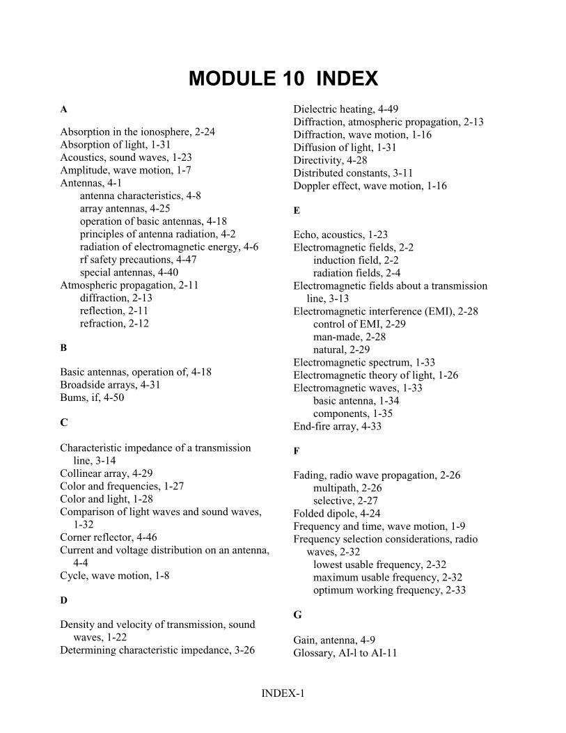
INDEX-1
MODULE 10 INDEX
A Absorption in the ionosphere, 2-24 Absorption of light, 1-31 Acoustics, sound waves, 1-23 Amplitude, wave motion, 1-7 Antennas, 4-1
antenna characteristics, 4-8 array antennas, 4-25 operation of basic antennas, 4-18 principles of antenna radiation, 4-2 radiation of electromagnetic energy, 4-6 rf safety precautions, 4-47 special antennas, 4-40
Atmospheric propagation, 2-11 diffraction, 2-13 reflection, 2-11 refraction, 2-12
B
Basic antennas, operation of, 4-18 Broadside arrays, 4-31 Bums, if, 4-50 C
Characteristic impedance of a transmission
line, 3-14 Collinear array, 4-29 Color and frequencies, 1-27 Color and light, 1-28 Comparison of light waves and sound waves,
1-32 Corner reflector, 4-46 Current and voltage distribution on an antenna,
4-4 Cycle, wave motion, 1-8 D
Density and velocity of transmission, sound
waves, 1-22 Determining characteristic impedance, 3-26
Dielectric heating, 4-49 Diffraction, atmospheric propagation, 2-13 Diffraction, wave motion, 1-16 Diffusion of light, 1-31 Directivity, 4-28 Distributed constants, 3-11 Doppler effect, wave motion, 1-16 E
Echo, acoustics, 1-23 Electromagnetic fields, 2-2
induction field, 2-2 radiation fields, 2-4
Electromagnetic fields about a transmission line, 3-13
Electromagnetic interference (EMI), 2-28 control of EMI, 2-29 man-made, 2-28 natural, 2-29
Electromagnetic spectrum, 1-33 Electromagnetic theory of light, 1-26 Electromagnetic waves, 1-33
basic antenna, 1-34 components, 1-35
End-fire array, 4-33 F
Fading, radio wave propagation, 2-26
multipath, 2-26 selective, 2-27
Folded dipole, 4-24 Frequency and time, wave motion, 1-9 Frequency selection considerations, radio
waves, 2-32 lowest usable frequency, 2-32 maximum usable frequency, 2-32 optimum working frequency, 2-33
G
Gain, antenna, 4-9 Glossary, AI-l to AI-11
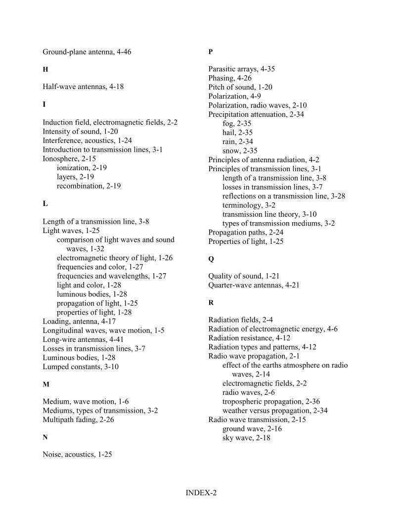
INDEX-2
Ground-plane antenna, 4-46 H
Half-wave antennas, 4-18 I
Induction field, electromagnetic fields, 2-2 Intensity of sound, 1-20 Interference, acoustics, 1-24 Introduction to transmission lines, 3-1 Ionosphere, 2-15
ionization, 2-19 layers, 2-19 recombination, 2-19
L
Length of a transmission line, 3-8 Light waves, 1-25
comparison of light waves and sound waves, 1-32
electromagnetic theory of light, 1-26 frequencies and color, 1-27 frequencies and wavelengths, 1-27 light and color, 1-28 luminous bodies, 1-28 propagation of light, 1-25 properties of light, 1-28
Loading, antenna, 4-17 Longitudinal waves, wave motion, 1-5 Long-wire antennas, 4-41 Losses in transmission lines, 3-7 Luminous bodies, 1-28 Lumped constants, 3-10 M
Medium, wave motion, 1-6 Mediums, types of transmission, 3-2 Multipath fading, 2-26 N
Noise, acoustics, 1-25
P
Parasitic arrays, 4-35 Phasing, 4-26 Pitch of sound, 1-20 Polarization, 4-9 Polarization, radio waves, 2-10 Precipitation attenuation, 2-34
fog, 2-35 hail, 2-35 rain, 2-34 snow, 2-35
Principles of antenna radiation, 4-2 Principles of transmission lines, 3-1
length of a transmission line, 3-8 losses in transmission lines, 3-7 reflections on a transmission line, 3-28 terminology, 3-2 transmission line theory, 3-10 types of transmission mediums, 3-2
Propagation paths, 2-24 Properties of light, 1-25 Q
Quality of sound, 1-21 Quarter-wave antennas, 4-21 R
Radiation fields, 2-4 Radiation of electromagnetic energy, 4-6 Radiation resistance, 4-12 Radiation types and patterns, 4-12 Radio wave propagation, 2-1
effect of the earths atmosphere on radio waves, 2-14
electromagnetic fields, 2-2 radio waves, 2-6 tropospheric propagation, 2-36 weather versus propagation, 2-34
Radio wave transmission, 2-15 ground wave, 2-16 sky wave, 2-18
INDEX-3
Reciprocity of antennas, 4-8 Reflection, atmospheric propagation, 2-11 Reflection of light, 1-30 Reflection, wave motion, 1-13 Reflections on a transmission line, 3-28 Refraction, acoustics, 1-23 Refraction, atmospheric propagation, 2-12 Refraction in the ionosphere, 2-20
angle of incidence, 2-22 density of layer, 2-21 frequency, 2-21 skip distance/skip zone, 2-24
Refraction of light, 1-30 Refraction, wave motion, 1-14 Resonance, acoustics, 1-24 Reverberation, acoustics, 1-24 Rhombic antennas, 4-42 S
Safety precautions, if, 4-47 Selective fading, 2-27 Sound waves, 1-17
acoustics, 1-23 characteristics, 1-19 density and velocity of transmission, 1-22 requirements for sound, 1-18 terms, 1-19
Special antennas, 4-40 Speed of light, 1-30 Standing waves on a transmission line, 3-43 T
Temperature inversion, 2-35 Terminating a transmission line, 3-38 Termination, 3-43 Terminology, 3-2 Transmission line theory, 3-10 Transmission losses, radio wave propagation,
2-27 freespace loss, 2-28 ground reflection loss, 2-28
Transmission mediums, types of, 3-2 Transverse waves, 1-5 Tropospheric propagation, 2-36
application of tropospheric scatter, 2-38 tropospheric scattering, 2-37
Turnstile antenna, 4-45
V
V antennas, 4-41 Variations in the ionosphere, 2-29
irregular variations, 2-30 regular variations, 2-29
Velocity of wave propagation, 3-24 Voltage change along a transmission line, 3-18
W
Wave motion, principles of, 1-2 characteristics, 1-9 in water, 1-3 longitudinal waves, 1-5 medium, 1-6 terms, 1-7 transverse waves, 1-5
Wave propagation, 1-1 electromagnetic spectrum, 1-33 electromagnetic waves, 1-33 light waves, 1-25 principles of wave motion, 1-2 sound waves, 1-17
Wavelength to frequency conversions, radio waves, 2-8
Wavelength, wave motion, 1-8 Wavelengths and frequencies, 1-27 Weather versus propagation, 2-34
precipitation attenuation, 2-34 temperature inversion, 2-35
Working aloft, precautions, 4-49

Assignment Questions
Information: The text pages that you are to study areprovided at the beginning of the assignment questions.

1
ASSIGNMENT 1
Textbook assignment: Chapter 1, “Wave Propagation,” pages 1-1 through 1-48._____________________________________________________________________________________
1-1. What is the major advantage of thetelegraph over earlier methods ofcommunication?
1. Range2. Speed3. Security4. Reliability
1-2. The spreading out of radio waves isreferred to as propagation and is used inwhich of the following Navy equipment?
1. Detection2. Communication3. Radar and navigation4. Each of the above
1-3. Radio-frequency waves CANNOT beseen for which of the following reasons?
1. Because radio-frequency energy islow powered
2. Because radio-frequency waves arebelow the sensitivity range of thehuman eye
3. Because the human eye detects onlymagnetic energy
4. Because radio-frequency waves areabove the sensitivity range of thehuman eye
1-4. Radio waves travel at what speed?
1. Speed of sound2. Speed of light3. Speed of the Earth's rotation4. Speed of the Earth's orbit around the
sun
1-5. Which of the following types of energyCANNOT be seen, heard, or felt?
1. Radio waves2. Sound waves3. Heat waves4. Light waves
1-6. A stone dropped into water creates aseries of expanding circles on the surfaceof the water. This is an example of whichof the following types of wave motion?
1. Transverse2. Concentric3. Longitudinal4. Compression
1-7. A sound wave that moves back and forthin the direction of propagation is anexample of which of the following typesof wave motion?
1. Composite2. Concentric3. Transverse4. Longitudinal
1-8. Which of the following terms is used forthe vehicle through which a wave travelsfrom point to point?
1. Medium2. Source3. Detector4. Receiver
1-9. Which of the following is NOT anelement necessary to propagate sound?
1. Medium2. Source3. Detector4. Reference
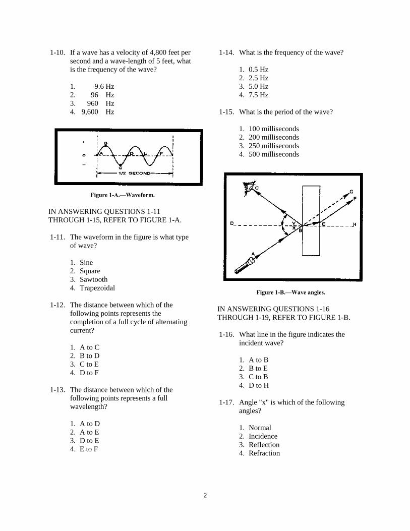
2
1-10. If a wave has a velocity of 4,800 feet persecond and a wave-length of 5 feet, whatis the frequency of the wave?
1. 9.6 Hz2. 96 Hz3. 960 Hz4. 9,600 Hz
Figure 1-A.—Waveform.
IN ANSWERING QUESTIONS 1-11THROUGH 1-15, REFER TO FIGURE 1-A.
1-11. The waveform in the figure is what typeof wave?
1. Sine2. Square3. Sawtooth4. Trapezoidal
1-12. The distance between which of thefollowing points represents thecompletion of a full cycle of alternatingcurrent?
1. A to C2. B to D3. C to E4. D to F
1-13. The distance between which of thefollowing points represents a fullwavelength?
1. A to D2. A to E3. D to E4. E to F
1-14. What is the frequency of the wave?
1. 0.5 Hz2. 2.5 Hz3. 5.0 Hz4. 7.5 Hz
1-15. What is the period of the wave?
1. 100 milliseconds2. 200 milliseconds3. 250 milliseconds4. 500 milliseconds
Figure 1-B.—Wave angles.
IN ANSWERING QUESTIONS 1-16THROUGH 1-19, REFER TO FIGURE 1-B.
1-16. What line in the figure indicates theincident wave?
1. A to B2. B to E3. C to B4. D to H
1-17. Angle "x" is which of the followingangles?
1. Normal2. Incidence3. Reflection4. Refraction
3
1-18. Line E to F represents which of thefollowing waves?
1. Normal2. Incident3. Refracted4. Reflected
1-19. Line D to H represents which of thefollowing references?
1. Normal2. Perpendicular3. Both 1 and 2 above4. Reflected line
1-20. Which of the following statements abouta wave is the law of reflection?
1. The angle of incidence is equal to therefracted wave
2. The angle of incidence is not equal tothe refracted wave
3. The angle of incidence is equal to theangle of reflection
4. The angle of incidence is not equal tothe angle of reflection
1-21. If a wave passes first through a densemedium and then through a less densemedium, which of the following angle-of-refraction conditions exists?
1. The angle of refraction is greater thanthe angle of incidence
2. The angle of refraction is less than theangle of incidence
3. The angle of refraction is equal to theangle of incidence
4. The wave will pass through in astraight line
1-22. The reception of an AM-band radiosignal over mountains can be explainedby which of the following principles ofwave propagation?
1. Reflection2. Refraction3. Diffraction4. Doppler effect
1-23. What wave propagation principleaccounts for the apparent increase infrequency as a train whistle approachesand the apparent decrease in frequency asit moves away?
1. Refraction2. Reflection3. Diffraction4. Doppler effect
1-24. Longitudinal wave disturbances thattravel through a medium are known aswhat type of waves?
1. Air2. Sound3. Radio4. Light
1-25. What are the three audible frequencyranges?
1. Subsonic, sonic, and supersonic2. Infrasonic, sonic, and ultrasonic3. Infrasonic, subsonic, and ultrasonic4. Infrasonic, subsonic, and supersonic
1-26. If a bell is placed in a jar and the air inthe jar is replaced with a gas of a higherdensity, what is the effect, if any, on thespeed of the sound when the bell is rung?
1. The sound stops2. The sound travels faster3. The sound travels slower4. The sound is not affected
1-27. Varying which of the following wavecharacteristics will cause the length ofsound waves to vary?
1. Phase2. Quality3. Amplitude4. Frequency
4
1-28. What are the three basic characteristicsof sound?
1. Amplitude, intensity, and quality2. Amplitude, pitch, and tone3. Pitch, intensity, and quality4. Pitch, frequency, and quality
1-29. If several musical instruments areplaying the same note, you should beable to distinguish one instrument fromanother because of which of thefollowing characteristics of sound?
1. Quality2. Overtones3. Frequency4. Intensity
1-30. Through which of the followingmediums will sound travel fastest, at theindicated temperature?
1. Air at 68º F2. Lead at 20º C3. Steel at 32º F4. Steel at 20º C
1-31. In sound terminology, which of thefollowing terms is the same as a wavereflection?
1. Echo2. Image3. Acoustics4. Refraction
1-32. Multiple reflections of sound waves arereferred to as
1. noise2. acoustics3. interference4. reverberation
1-33. Two out-of-phase waves of the samefrequency that are moving through thesame medium are said to present whichof the following types of interference?
1. Additive2. Constructive3. Both 1 and 2 above4. Subtractive
1-34. A cavity that vibrates at its own naturalfrequency and produces a sound that islouder than at other frequencies isdemonstrating which of the followingsound characteristics?
1. Noise2. Quality3. Resonance4. Reverberation
1-35. Energy in the form of light can beproduced through which of the followingmeans?
1. Chemical2. Electrical3. Mechanical4. Each of the above
1-36. The scientist, J. C. Maxwell, developedthe theory that small packets ofelectromagnetic energy called photonsproduce
1. sound2. noise3. echoes4. light
1-37. A large volume of light radiating in agiven direction is referred to as a
1. ray2. beam3. shaft4. pencil
5
1-38. Which of the following units ofmeasurement is/are used to measure veryshort wavelengths of light?
1. Angstrom ( �2. Millimicron3. Both 1 and 2 above4. Millimeter
1-39. What are the primary colors of light?
1. Red, blue, and yellow2. Red, blue, and green3. Red, violet, and indigo4. Blue, green, and violet
1-40. What are the secondary colors of light?
1. Orange, yellow, and blue-green2. Magenta, yellow, and cyan3. Purple, yellow, and black4. Red, white, and blue
1-41. What causes sunlight to separate intodifferent wavelengths and display arainbow of colors when passed through aprism?
1. Refraction2. Reflection3. Dispersion4. Diffraction
1-42. The sun, gas flames, and electric lightfilaments are visible because they are
1. opaque2. transparent3. nonluminous4. self-luminous
1-43. Substances that transmit almost all of thelight waves falling upon them possesswhich of the following properties?
1. Opaqueness2. Transparence3. Translucence4. Self-lumination
1-44. Some substances are able to transmitlight waves but objects cannot be seenthrough them. Which of the followingproperties does this statement describe?
1. Opaqueness2. Transparence3. Translucence4. Self-lumination
1-45. The speed of light depends on themedium through which light travels. Forwhich of the following reasons does lighttravel through empty space faster thanthrough an object such as glass?
1. Space is less dense than glass2. Space is more dense than glass3. Glass reflects the light back to the
source4. Glass refracts the light, causing the
light to travel in all directions
1-46. If a light wave strikes a sheet of glass at aperpendicular angle, what is the effect, ifany, on the light wave?
1. The wave is completely absorbed2. The wave is reflected back toward the
source3. The wave is refracted as it passes
through the glass4. The wave is unchanged and continues
in a straight line
1-47. The amount of absorption of the lightthat strikes an object is determined by theobject’s
1. color2. purity3. density4. complexity
6
1-48. In a comparison of waves of light andsound as they travel from an air intowater, how is the speed of (a) light wavesand (b) sound waves affected?
1. (a) Increased (b) increased2. (a) Increased (b) decreased3. (a) Decreased (b) decreased4. (a) Decreased (b) increased
1-49. Which of the following waves are NOT aform of electromagnetic energy?
1. Heat waves2. Sound waves3. Light waves4. Radio waves
1-50. The electromagnetic spectrum representsthe entire range of electromagnetic wavesarranged in the order of their
1. color2. frequency3. visibility4. application
1-51. Which of the following portions of thefrequency spectrum contains the highestfrequency?
1. X-ray2. Radar3. Light4. Cosmic
1-52. Which of the following electronicdevices is used to radiate and/or collectelectromagnetic waves?
1. Antenna2. Receiver3. Transmitter4. Transmission line
1-53. The electric field and magnetic fieldcombine to form which of the followingtypes of waves?
1. Spherical2. Elliptical3. Electromagnetic4. Each of the above
1-54. The magnetic field radiated from anantenna is produced by what electricalproperty?
1. Voltage2. Current3. Reactance4. Resistance
1-55. The electric field radiated from anantenna is produced by what electricalproperty?
1. Voltage2. Current3. Reactance4. Resistance
1-56. Applying rf energy to the elements of anantenna results in what phase relationshipbetween voltage and current?
1. Voltage lags current by 90 degrees2. Voltage leads current by 90 degrees3. Voltage and current are 180 degrees
out of phase4. Voltage and current are in phase
1-57. What field exists close to the conductorof an antenna and carries the current?
1. Electric2. Magnetic3. Induction4. Radiation
7
1-58. What field travels through space afterbeing detached from the current-carryingrod of an antenna?
1. Electric2. Magnetic3. Induction4. Radiation
1-59. Electric and magnetic fields on anantenna reach their maximum intensity atwhich of the following times?
1. When they are a full cycle apart2. When they are three-quarter cycle
apart3. When they are a half-cycle apart4. When they are a quarter-cycle apart
8
ASSIGNMENT 2
Textbook assignment: Chapter 2, “Radio Wave Propagation,” pages 2-1 through 2-47._______________________________________________________________________________________
2-1. The induction field is made up of which ofthe following fields?
1. E field only2. H field only3. Both E and H fields
2-2. After the radiation field leaves an antenna,what is the relationship between the E andH fields with respect to (a) phase and(b) physical displacement in space?
1. (a) In phase (b) 90 degrees2. (a) Out of phase (b) 90 degrees3. (a) In phase (b) 180 degrees4. (a) Out of phase (b) 180 degrees
2-3. What is the first harmonic of a radio wavethat has a fundamental frequency of 2,000kHz?
1. 6,000 kHz2. 2,000 kHz3. 3,000 kHz4. 4,000 kHz
2-4. In a radio wave with a fundamentalfrequency of 1.5 kHz, which of thefollowing frequencies is NOT a harmonic?
1. 6,000 kHz2. 5,000 kHz3. 3,000 kHz4. 4,000 kHz
2-5. A radio wave with a frequency of 32 kHzis part of which of the following frequencybands?
1. The lf band2. The mf band3. The hf band4. The vhf band
2-6. A frequency of 3.5 GHz falls into what rfband?
1. High2. Very high3. Super high4. Extremely high
2-7. A radio wavelength expressed as 250meters may also be expressed as howmany feet?
1. 4102. 8203. 1,2304. 1,640
2-8. An increase in the frequency of a radiowave will have what effect, if any, on thevelocity of the radio wave?
1. Increase2. Decrease3. None
2-9. An increase in frequency of a radio wavewill have what effect, if any, on thewavelength of the radio wave?
1. Increase2. Decrease3. None
2-10. What is the frequency, in kiloHertz, of aradio wave that is 40 meters long?
1. 752. 7503. 7,5004. 75,000
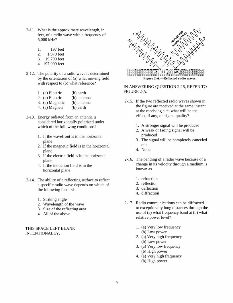
9
2-11. What is the approximate wavelength, infeet, of a radio wave with a frequency of5,000 kHz?
1. 197 feet2. 1,970 feet3. 19,700 feet4. 197,000 feet
2-12. The polarity of a radio wave is determinedby the orientation of (a) what moving fieldwith respect to (b) what reference?
1. (a) Electric (b) earth2. (a) Electric (b) antenna3. (a) Magnetic (b) antenna4. (a) Magneti (b) earth
2-13. Energy radiated from an antenna isconsidered horizontally polarized underwhich of the following conditions?
1. If the wavefront is in the horizontalplane
2. If the magnetic field is in the horizontalplane
3. If the electric field is in the horizontalplane
4. If the induction field is in thehorizontal plane
2-14. The ability of a reflecting surface to reflecta specific radio wave depends on which ofthe following factors?
1. Striking angle2. Wavelength of the wave3. Size of the reflecting area4. All of the above
THIS SPACE LEFT BLANKINTENTIONALLY.
Figure 2-A.—Reflected radio waves.
IN ANSWERING QUESTION 2-15, REFER TOFIGURE 2-A.
2-15. If the two reflected radio waves shown inthe figure are received at the same instantat the receiving site, what will be theeffect, if any, on signal quality?
1. A stronger signal will be produced2. A weak or fading signal will be
produced3. The signal will be completely canceled
out4. None
2-16. The bending of a radio wave because of achange in its velocity through a medium isknown as
1. refraction2. reflection3. deflection4. diffraction
2-17. Radio communications can be diffractedto exceptionally long distances through theuse of (a) what frequency band at (b) whatrelative power level?
1. (a) Very low frequency(b) Low power
2. (a) Very high frequency(b) Low power
3. (a) Very low frequency(b) High power
4. (a) Very high frequency(b) High power
10
2-18. Electrically charged particles that affectthe propagation of radio waves are foundin what atmospheric layer?
1. Troposphere2. Ionosphere3. Chronosphere4. Stratosphere
2-19. Most weather phenomena take place inwhich of the following region of theatmosphere?
1. Troposphere2. Ionosphere3. Chronosphere4. Stratosphere
2-20. Radio wave propagation has the leasteffect because of its constancy on whichof the following atmospheric layers?
1. Troposphere2. Ionosphere3. Chronosphere4. Stratosphere
2-21. Long range, surface-wavecommunications are best achieved whenthe signal is transmitted over seawaterwith (a) what polarization at (b) whatrelative frequency?
1. (a) Vertical (b) Low2. (a) Vertical (b) High3. (a) Horizontal (b) High4. (a) Horizontal (b) Low
2-22. The Navy’s long-range vlf broadcasts arepossible because of the advantages ofwhich of the following types ofpropagation?
1. Diffraction2. Ionospheric refraction3. Repeated reflection and refraction4. Both 2 and 3 above
2-23. A space wave (a) is primarily a result ofrefraction in what atmospheric layer and(b) extends approximately what distancebeyond the horizon?
1. (a) Ionosphere(b) One-tenth farther
2. (a) Ionosphere(b) One-third farther
3. (a) Troposphere(b) One-third farther
4. (a) Troposphere(b) One-tenth farther
2-24. The signal of a space wave is sometimessignificantly reduced at the receiving sitebecause of which of the followinginteractions?
1. Space-wave refraction2. Space-wave reflections3. Ground-wave diffraction4. Ground-wave reflections
2-25. For long-range communications in the hfband, which of the following types ofwaves is most satisfactory?
1. Sky wave2. Space wave3. Surface wave4. Reflected ground wave
2-26. Ionization in the atmosphere is producedchiefly by which of the following types ofradiation?
1. Alpha radiation2. Cosmic radiation3. Infrared radiation4. Ultraviolet radiation
2-27. Ultraviolet waves of higher frequenciesproduce ionized layers at what relativealtitude(s)?
1. Lower2. Higher3. Both 1 and 2 above
11
2-28. The density of ionized layers is normallygreatest during which of the followingperiods?
1. At night2. Before sunrise3. Between early morning and late
afternoon4. Between afternoon and sunset
2-29. Compared to the other ionospheric layersat higher altitudes, the ionization densityof the D layer is
1. about the same2. relatively low3. relatively high
2-30. What two layers in the ionosphererecombine and largely disappear at night?
1. D and F2. D and E3. E and F24. F1 and F2
2-31. For hf-radio communications coveringlong distances, what is the most importantlayer of the ionosphere?
1. C2. D3. E4. F
2-32. Refraction of a sky wave in the ionosphereis influenced by which of the followingfactors?
1. Ionospheric density2. Frequency of the wave3. Angle of incidence of the wave4. All of the above
2-33. A 10-MHz wave entering the ionosphereat an angle greater than its critical anglewill pass through the ionosphere and belost in space unless which of the followingactions is taken?
1. The ground wave is canceled2. The frequency of the wave is increased3. The frequency of the wave is decreased4. The ground wave is reinforced
2-34. The distance between the transmitter andthe nearest point at which refracted wavesreturn to earth is referred to as the
1. skip distance2. return distance3. reception distance4. ground-wave distance
2-35. When ground-wave coverage is LESSthan the distance between the transmitterand the nearest point at which therefracted waves return to earth, which ofthe following reception possibilitiesshould you expect?
1. No sky-wave2. Weak ground wave3. A zone of silence4. Strong ground wave
2-36. The greatest amount of absorption takesplace in the ionosphere under which of thefollowing conditions?
1. When sky wave intensity is the greatest2. When collision of particles is least3. When the density of the ionized layer
is the greatest4. When precipitation is greatest
2-37. Which of the following layers provide thegreatest amount of absorption to theionospheric wave?
1. D and E2. D and F13. E and F14. F1 and F2
12
2-38. If the signal strength of an incoming signalis reduced for a prolonged period, whattype of fading is most likely involved?
1. Selective2. Multipath3. Absorption4. Polarization
2-39. Radio waves that arrive at a receiving sitealong different paths can cause signalfading if these waves have different
1. velocities2. amplitudes3. phase relationships4. modulation percentages
2-40. The technique of reducing multipathfading by using several receiving antennasat different locations is known as whattype of diversity?
1. Space2. Receiver3. Frequency4. Modulation
2-41. The amount of rf energy lost because ofground reflections depends on which ofthe following factors?
1. Angle of incidence2. Ground irregularities3. Frequency of the wave4. Each of the above
2-42. Receiving sites located near industrialareas can expect to have exceptionallylarge losses in signal quality as a result ofwhich of the following propagationsituations?
1. Absorption2. Multihop refraction3. Natural interference4. Man-made interference
2-43. Which of the following ionosphericvariation causes densities to vary with theaxial rotation of the sun?
1. Daily variation2. Seasonal variation3. 27-day sunspot cycle4. 11-year sunspot cycle
2-44. Which of the following ionosphericvariation causes densities to vary with theposition of the earth in its orbit around thesun?
1. Daily variation2. Seasonal variation3. 27-day sunspot cycle4. 11-year sunspot cycle
2-45. Which of the following ionosphericvariation causes densities to vary with thetime of the day?
1. Daily variation2. Seasonal variation3. 27-day sunspot cycle4. 11-year sunspot cycle
2-46. What relative range of operatingfrequencies is required during periods ofmaximum sunspot activity?
1. Lower2. Medium3. Higher
2-47. What factor significantly affects thefrequency of occurrence of the sporadic-Elayer?
1. Seasons2. Latitude3. Weather conditions4. Ionospheric storms
13
2-48. What effect can the sporadic-E layer haveon the propagation of sky waves?
1. Causes multipath interference2. Permits long distance communications
at unusually high frequencies3. Permits short-distance communications
in the normal skip zone4. Each of the above
2-49. A sudden and intense burst of ultravioletlight is especially disruptive tocommunications in which of the followingfrequency bands?
1. Hf2. Mf3. Lf4. Vlf
2-50. The density of what ionosphere layerincreases because of a violent eruption onthe surface of the sun?
1. D2. E3. F14. F2
2-51. Which irregular variation in ionosphericconditions can cause a waiting period ofseveral days before communicationsreturn to normal?
1. Sporadic E2. Ionospheric storms3. Sudden ionospheric disturbance4. Each of the above
2-52. For a radio wave entering the atmosphereof the earth at a given angle, the highestfrequency at which refraction will occur isknown by which of the following terms?
1. Usable frequency2. Refraction frequency3. Maximum usable frequency4. Optimum working frequency
2-53. The most consistent communications canbe expected at which of the followingfrequencies?
1. Critical frequency2. Maximum usable frequency3. Maximum working frequency4. Optimum working frequency
2-54. If the optimum working frequency for acommunications link is 4,250 kHz, what isthe approximate maximum usablefrequency?
1. 4,500 kHz2. 5,000 kHz3. 5,500 kHz4. 6,000 kHz
2-55. In determining the success of radiotransmission, which of the followingfactors is the LEAST predictable?
1. Antenna capabilities2. Weather conditions along the path of
communication3. Density of ionized layers4. Presence of ionized layers
2-56. At frequencies above 100 MHz, thegreatest attenuation of rf energy fromraindrops is caused by which of thefollowing factors?
1. Ducting2. Heat loss3. Scattering4. Absorption
2-57. Under certain conditions, such as ducting,line-of-sight radio waves often propagatefor distances far beyond their normalranges because of which of the followingfactors?
1. Low cloud masses2. Ionospheric storms3. Temperature inversions4. Frequency fluctuations

14
2-58. When ducting is present in theatmosphere, multihop refraction ofline-of-sight transmission can occurbecause of which of the following factors?
1. Operating frequency of the transmitter2. Height of the transmitting antenna3. Angle of incidence of the radio wave4. Each of the above
2-59. A propagation technique used to extenduhf transmission range beyond the horizonuses which of the following propagationcharacteristics?
1. Ground reflection2. Ionospheric scatter3. Tropospheric scatter4. Atmospheric refraction
2-60. Communications by tropospheric scattercan be affected by which of the followingconditions?
1. Sunspot activity2. Atmospheric conditions3. Ionospheric disturbances4. All of the above
2-61. What effect, if any, does the radiationangle of a transmitting antenna have onthe reception of communications bytropospheric scatter?
1. The lower the angle, the weaker thesignal
2. The lower the angle, the stronger thesignal
3. The lower the angle, the moresusceptible the signal is to distortion
4. None
2-62. Which of the following descriptions oftropospheric scatter signal reception isNOT true?
1. Receiver signal strength decreases asthe turbulence height is increased
2. The level of reception depends on thenumber of turbulences causing scatter
3. The energy received is the portion ofthe wave reradiated by the turbulence
4. Increased communications distanceenables more turbulence to act on thesignal, thereby raising the receivedsignal level
2-63. The tropospheric scatter signal is oftencharacterized by very rapid fading causedby which of the following factors?
1. Extreme path lengths2. Multipath propagation3. Turbulence in the atmosphere4. Angle of the transmitted beam
2-64. For which of the followingcommunications situations wouldturbulence in the troposphere scattertransmission?
1. 10 MHz, range 200 miles2. 30 MHz, range 800 miles3. 50 MHz, range 600 miles4. 100 MHz, range 400 miles
15
ASSIGNMENT 3
Textbook assignment: Chapter 3, “Principles of Transmission Lines,” pages 3-1 through 3-58. ___________________________________________________________________________________
3-1. A transmission line is designed to perform
which of the following functions?
1. Disperse energy in all directions 2. Detune a transmitter to match the load 3. Guide electrical energy from point to
point 4. Replace the antenna in a
communications system
3-2. All transmission lines must have two ends, the input end and the output end. What other name is given to the input end?
1. Sending end 2. Generator end 3. Transmitter end 4. Each of the above
3-3. A measurement of the voltage to current ratio (Ein/I in) at the input end of a transmission line is called the
1. input-gain rate 2. input impedance 3. output impedance 4. voltage-gain ratio
3-4. Which of the following lines is NOT a transmission medium?
1. Load line 2. Coaxial line 3. Two-wire line 4. Twisted-pair line
3-5. Electrical power lines are most often made of which of the following types of transmission lines?
1. Twin-lead line 2. Shielded-pair line 3. Two-wire open line 4. Two-wire ribbon line
3-6. Uniform capacitance throughout the length of the line is an advantage of which of the following transmission lines?
1. Coaxial line 2. Twisted pair 3. Shielded pair 4. Two-wire open line
3-7. What is the primary advantage of a rigid coaxial line?
1. Low radiation losses 2. Inexpensive construction 3. Low high-frequency losses 4. Each of the above
3-8. Which of the following wave-guides is seldom used because of its large energy loss characteristics?
1. Metallic 2. Dielectric 3. Elliptical 4. Cylindrical
3-9. To some degree, transmission lines always exhibit which of the following types of losses?
1. I2R 2. Inductor 3. Dielectric 4. Each of the above
3-10. Skin effect is classified as which of the following types of loss?
1. Copper 2. Voltage 3. Induction 4. Dielectric
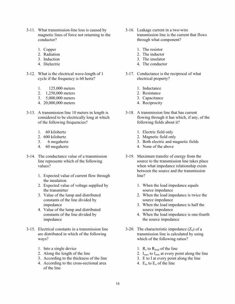
16
3-11. What transmission-line loss is caused by magnetic lines of force not returning to the conductor?
1. Copper 2. Radiation 3. Induction 4. Dielectric
3-12. What is the electrical wave-length of 1 cycle if the frequency is 60 hertz?
1. 125,000 meters 2. 1,250,000 meters 3. 5,000,000 meters 4. 20,000,000 meters
3-13. A transmission line 10 meters in length is considered to be electrically long at which of the following frequencies?
1. 60 kilohertz 2. 600 kilohertz 3. 6 megahertz 4. 60 megahertz
3-14. The conductance value of a transmission line represents which of the following values?
1. Expected value of current flow through
the insulation 2. Expected value of voltage supplied by
the transmitter 3. Value of the lump and distributed
constants of the line divided by impedance
4. Value of the lump and distributed constants of the line divided by impedance
3-15. Electrical constants in a transmission line
are distributed in which of the following ways?
1. Into a single device 2. Along the length of the line 3. According to the thickness of the line 4. According to the cross-sectional area
of the line
3-16. Leakage current in a two-wire transmission line is the current that flows through what component?
1. The resistor 2. The inductor 3. The insulator 4. The conductor
3-17. Conductance is the reciprocal of what electrical property?
1. Inductance 2. Resistance 3. Capacitance 4. Reciprocity
3-18. A transmission line that has current flowing through it has which, if any, of the following fields about it?
1. Electric field only 2. Magnetic field only 3. Both electric and magnetic fields 4. None of the above
3-19. Maximum transfer of energy from the source to the transmission line takes place when what impedance relationship exists between the source and the transmission line?
1. When the load impedance equals
source impedance 2. When the load impedance is twice the
source impedance 3. When the load impedance is half the
source impedance 4. When the load impedance is one-fourth
the source impedance
3-20. The characteristic impedance (Z0) of a transmission line is calculated by using which of the following ratios?
1. Rs to Rload of the line 2. Imax to Imin at every point along the line 3. E to I at every point along the line 4. Ein to Eo of the line
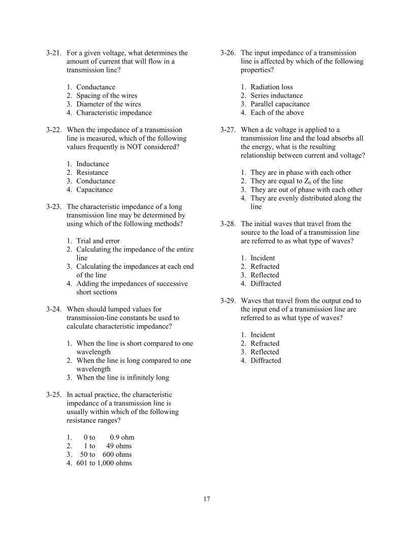
17
3-21. For a given voltage, what determines the amount of current that will flow in a transmission line?
1. Conductance 2. Spacing of the wires 3. Diameter of the wires 4. Characteristic impedance
3-22. When the impedance of a transmission line is measured, which of the following values frequently is NOT considered?
1. Inductance 2. Resistance 3. Conductance 4. Capacitance
3-23. The characteristic impedance of a long transmission line may be determined by using which of the following methods?
1. Trial and error 2. Calculating the impedance of the entire
line 3. Calculating the impedances at each end
of the line 4. Adding the impedances of successive
short sections
3-24. When should lumped values for transmission-line constants be used to calculate characteristic impedance?
1. When the line is short compared to one
wavelength 2. When the line is long compared to one
wavelength 3. When the line is infinitely long
3-25. In actual practice, the characteristic impedance of a transmission line is usually within which of the following resistance ranges?
1. 0 to 0.9 ohm 2. 1 to 49 ohms 3. 50 to 600 ohms 4. 601 to 1,000 ohms
3-26. The input impedance of a transmission line is affected by which of the following properties?
1. Radiation loss 2. Series inductance 3. Parallel capacitance 4. Each of the above
3-27. When a dc voltage is applied to a transmission line and the load absorbs all the energy, what is the resulting relationship between current and voltage?
1. They are in phase with each other 2. They are equal to Z0 of the line 3. They are out of phase with each other 4. They are evenly distributed along the
line
3-28. The initial waves that travel from the source to the load of a transmission line are referred to as what type of waves?
1. Incident 2. Refracted 3. Reflected 4. Diffracted
3-29. Waves that travel from the output end to the input end of a transmission line are referred to as what type of waves?
1. Incident 2. Refracted 3. Reflected 4. Diffracted
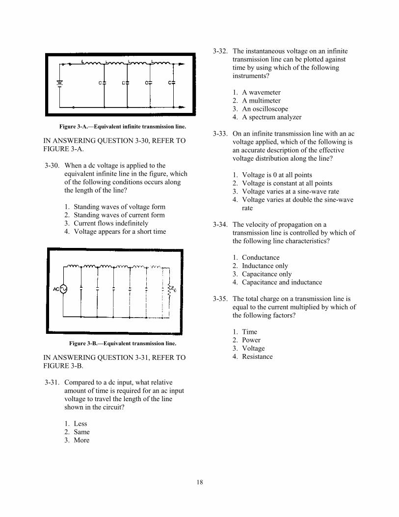
18
Figure 3-A.—Equivalent infinite transmission line.
IN ANSWERING QUESTION 3-30, REFER TO FIGURE 3-A. 3-30. When a dc voltage is applied to the
equivalent infinite line in the figure, which of the following conditions occurs along the length of the line?
1. Standing waves of voltage form 2. Standing waves of current form 3. Current flows indefinitely 4. Voltage appears for a short time
Figure 3-B.—Equivalent transmission line.
IN ANSWERING QUESTION 3-31, REFER TO FIGURE 3-B. 3-31. Compared to a dc input, what relative
amount of time is required for an ac input voltage to travel the length of the line shown in the circuit?
1. Less 2. Same 3. More
3-32. The instantaneous voltage on an infinite transmission line can be plotted against time by using which of the following instruments?
1. A wavemeter 2. A multimeter 3. An oscilloscope 4. A spectrum analyzer
3-33. On an infinite transmission line with an ac
voltage applied, which of the following is an accurate description of the effective voltage distribution along the line?
1. Voltage is 0 at all points 2. Voltage is constant at all points 3. Voltage varies at a sine-wave rate 4. Voltage varies at double the sine-wave
rate
3-34. The velocity of propagation on a transmission line is controlled by which of the following line characteristics?
1. Conductance 2. Inductance only 3. Capacitance only 4. Capacitance and inductance
3-35. The total charge on a transmission line is equal to the current multiplied by which of the following factors?
1. Time 2. Power 3. Voltage 4. Resistance
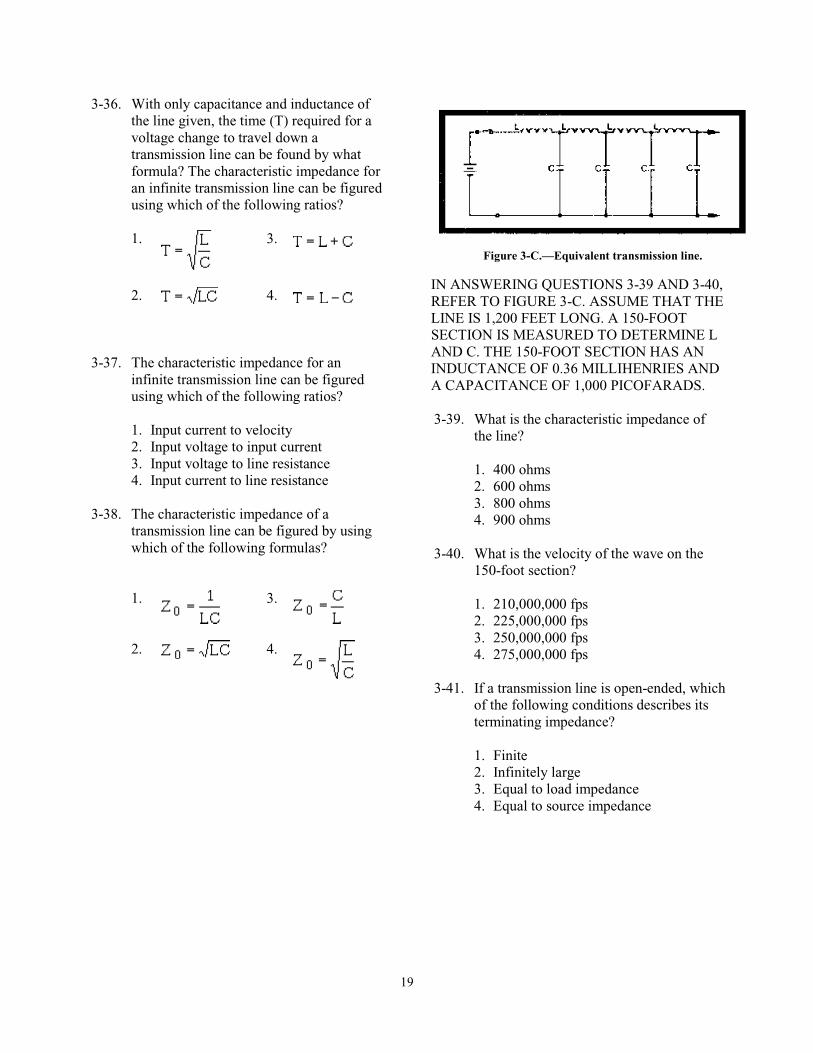
19
3-36. With only capacitance and inductance of the line given, the time (T) required for a voltage change to travel down a transmission line can be found by what formula? The characteristic impedance for an infinite transmission line can be figured using which of the following ratios?
1.
3.
2.
4.
3-37. The characteristic impedance for an infinite transmission line can be figured using which of the following ratios?
1. Input current to velocity 2. Input voltage to input current 3. Input voltage to line resistance 4. Input current to line resistance
3-38. The characteristic impedance of a
transmission line can be figured by using which of the following formulas?
1.
3.
2. 4.
Figure 3-C.—Equivalent transmission line.
IN ANSWERING QUESTIONS 3-39 AND 3-40, REFER TO FIGURE 3-C. ASSUME THAT THE LINE IS 1,200 FEET LONG. A 150-FOOT SECTION IS MEASURED TO DETERMINE L AND C. THE 150-FOOT SECTION HAS AN INDUCTANCE OF 0.36 MILLIHENRIES AND A CAPACITANCE OF 1,000 PICOFARADS. 3-39. What is the characteristic impedance of
the line?
1. 400 ohms 2. 600 ohms 3. 800 ohms 4. 900 ohms
3-40. What is the velocity of the wave on the 150-foot section?
1. 210,000,000 fps 2. 225,000,000 fps 3. 250,000,000 fps 4. 275,000,000 fps
3-41. If a transmission line is open-ended, which of the following conditions describes its terminating impedance?
1. Finite 2. Infinitely large 3. Equal to load impedance 4. Equal to source impedance
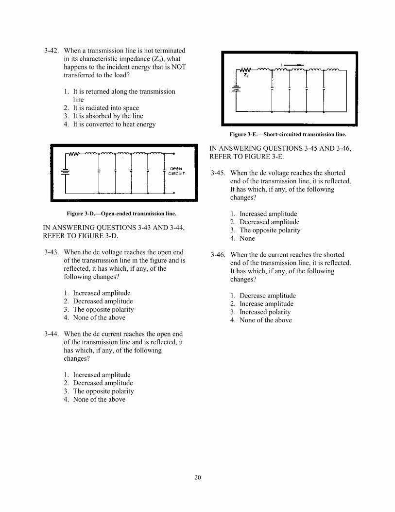
20
3-42. When a transmission line is not terminated in its characteristic impedance (Z0), what happens to the incident energy that is NOT transferred to the load?
1. It is returned along the transmission
line 2. It is radiated into space 3. It is absorbed by the line 4. It is converted to heat energy
Figure 3-D.—Open-ended transmission line.
IN ANSWERING QUESTIONS 3-43 AND 3-44, REFER TO FIGURE 3-D. 3-43. When the dc voltage reaches the open end
of the transmission line in the figure and is reflected, it has which, if any, of the following changes?
1. Increased amplitude 2. Decreased amplitude 3. The opposite polarity 4. None of the above
3-44. When the dc current reaches the open end
of the transmission line and is reflected, it has which, if any, of the following changes?
1. Increased amplitude 2. Decreased amplitude 3. The opposite polarity 4. None of the above
Figure 3-E.—Short-circuited transmission line.
IN ANSWERING QUESTIONS 3-45 AND 3-46, REFER TO FIGURE 3-E. 3-45. When the dc voltage reaches the shorted
end of the transmission line, it is reflected. It has which, if any, of the following changes?
1. Increased amplitude 2. Decreased amplitude 3. The opposite polarity 4. None
3-46. When the dc current reaches the shorted end of the transmission line, it is reflected. It has which, if any, of the following changes?
1. Decrease amplitude 2. Increase amplitude 3. Increased polarity 4. None of the above
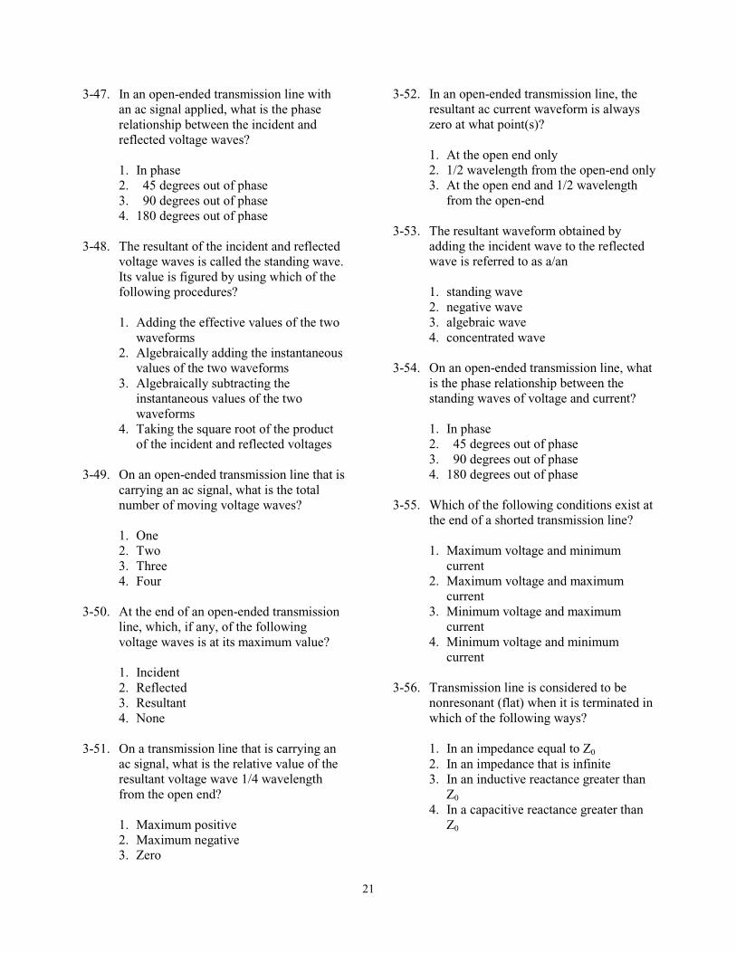
21
3-47. In an open-ended transmission line with an ac signal applied, what is the phase relationship between the incident and reflected voltage waves?
1. In phase 2. 45 degrees out of phase 3. 90 degrees out of phase 4. 180 degrees out of phase
3-48. The resultant of the incident and reflected voltage waves is called the standing wave. Its value is figured by using which of the following procedures?
1. Adding the effective values of the two
waveforms 2. Algebraically adding the instantaneous
values of the two waveforms 3. Algebraically subtracting the
instantaneous values of the two waveforms
4. Taking the square root of the product of the incident and reflected voltages
3-49. On an open-ended transmission line that is
carrying an ac signal, what is the total number of moving voltage waves?
1. One 2. Two 3. Three 4. Four
3-50. At the end of an open-ended transmission line, which, if any, of the following voltage waves is at its maximum value?
1. Incident 2. Reflected 3. Resultant 4. None
3-51. On a transmission line that is carrying an ac signal, what is the relative value of the resultant voltage wave 1/4 wavelength from the open end?
1. Maximum positive 2. Maximum negative 3. Zero
3-52. In an open-ended transmission line, the resultant ac current waveform is always zero at what point(s)?
1. At the open end only 2. 1/2 wavelength from the open-end only 3. At the open end and 1/2 wavelength
from the open-end
3-53. The resultant waveform obtained by adding the incident wave to the reflected wave is referred to as a/an
1. standing wave 2. negative wave 3. algebraic wave 4. concentrated wave
3-54. On an open-ended transmission line, what is the phase relationship between the standing waves of voltage and current?
1. In phase 2. 45 degrees out of phase 3. 90 degrees out of phase 4. 180 degrees out of phase
3-55. Which of the following conditions exist at the end of a shorted transmission line?
1. Maximum voltage and minimum
current 2. Maximum voltage and maximum
current 3. Minimum voltage and maximum
current 4. Minimum voltage and minimum
current
3-56. Transmission line is considered to be nonresonant (flat) when it is terminated in which of the following ways?
1. In an impedance equal to Z0 2. In an impedance that is infinite 3. In an inductive reactance greater than
Z0 4. In a capacitive reactance greater than
Z0
22
3-57. Of the following terms, which one is used for the nonresonant transmission line?
1. A tuned line 2. A shorted line 3. An untuned line 4. A terminated line
3-58. A transmission line that is resonant is sometimes referred to as which of the following types of lines?
1. Tuned 2. Matched 3. Untuned 4. Unmatched
3-59. A short-circuited section of transmission line that is an odd number of quarter-wavelengths long shows the same characteristics as which of the following devices?
1. A series-resonant circuit 2. A parallel-resonant circuit 3. An inductive reactance equal to Z0 4. A capacitive reactance equal to Z0
3-60. Which of the following circuits appears as a very high resistance at resonance?
1. Nonresonant 2. Series-resonant 3. Parallel-resonant 4. Each of the above
3-61. When a series-resonant circuit is resonant at a frequency above the generator frequency, it acts as what type of circuit?
1. Open 2. Resistive 3. Inductive 4. Capacitive
3-62. Which of the following sections of transmission line can be used as a parallel-resonant circuit?
1. A shorted 1/4-wavelength section 2. An open 1/4-wavelength section 3. A shorted 1/2-wavelength section 4. An open 3/4-wavelength section
3-63. A generator connected to an open-ended line greater than 1/4 wave-length but less than 1/2 wave-length senses which of the following circuit component characteristics?
1. Zero reactance 2. Low resistance 3. Inductive reactance 4. Capacitive reactance
3-64. Which of the following conditions of current (I) and impedance (Z) exist at even quarter-wave points on a shorted transmission line?
1. Low I, low Z 2. Low I, high Z 3. High I, high Z 4. High I, low Z
3-65. What is the maximum distance, in wavelengths (λ), between adjacent zero-current points on an open-circuited line?
1. 1 λ 2. 1/2 λ 3. 1/4 λ 4. 1/8 λ
3-66. When a line is terminated in a capacitance, the capacitor performs which, if any, of the following circuit actions?
1. It absorbs all the energy 2. It reflects all the energy 3. It reacts as if it were a short 4. None
23
3-67. When a transmission line is terminated in an inductive reactance, which, if any, of the following phase shifts takes place with respect to the current and voltage?
1. Only voltage is phase-shifted 2. Only current is phase-shifted 3. Both voltage and current are phase-
shifted 4. None
3-68. When a transmission line is terminated in a resistance greater than Z0, which of the following conditions exist?
1. The end of the line appears as an open
circuit 2. Standing waves appear on the line 3. Voltage is maximum and current is
minimum at the end of the line 4. Each of the above
3-69. On a transmission line, reflections begin at which of the following locations?
1. At the load 2. At the source 3. At the middle 4. At the half-wavelength point
3-70. The ratio of maximum voltage to minimum voltage on a transmission line is referred to as the
1. rswr 2. pswr 3. vswr 4. iswr
3-71. Which of the following ratios samples the magnetic field along a line?
1. Vswr 2. Pswr 3. Iswr 4. Rswr
24
ASSIGNMENT 4
Textbook assignment: Chapter 4, “Antennas,” pages 4-1 through 4-60. ___________________________________________________________________________________
4-1. Radio energy is transmitted through which of the following mediums?
1. Rock 2. Soil 3. Water 4. Space
4-2. Energy is transmitted from a transmitter into space using which of the following devices?
1. A receiver 2. A delay line 3. A receiving antenna 4. A transmitting antenna
4-3. Transmitted rf energy takes what form as it is sent into space?
1. A magnetic field only 2. An electric field only 3. An electromagnetic field 4. A static dielectric field
4-4. The dimensions of a transmitting antenna are determined by which of the following factors?
1. Transmitted power 2. Transmitted frequency 3. Distance to the receiver 4. Antenna height above the ground
4-5. A device used to radiate or receive electromagnetic wave energy is referred to as a/an
1. feeder 2. antenna 3. transmitter 4. coupling device
4-6. An antenna that can be mounted to radiate rf energy either vertically or horizontally is classified as which of the following types?
1. Hertz 2. Marconi 3. Quarter-wave 4. Both 2 and 3 above
4-7. A complete antenna system consists of which of the following components?
1. A feeder, a coupling device, and a
transmitter 2. A feeder line, a coupling device, and
an antenna 3. An antenna, a transmission line, and a
receiver 4. An impedance-matching device, a
feeder, and a transmission line
4-8. What component in an antenna system transfers energy from the transmitter to the antenna?
1. A feeder 2. A delay line 3. A choke joint 4. A rotating joint
4-9. The type, size, and shape of an antenna are determined by which of the following factors?
1. Power output of the transmitter 2. Transmitter frequency 3. Direction to the receiver 4. Each of the above

25
4-10. Moving electric and magnetic fields in space have what (a) phase and (b) angular relationships?
1. (a) In phase
(b) Perpendicular 2. (a) In phase
(b) Displaced 45º 3. (a) Out of phase
(b) Displaced 45º 4. (a) Out of phase
(b) Perpendicular
4-11. What is the length of each half of the wire for a dipole antenna?
1. Wavelength 2. 3/4 wavelength 3. 1/2 wavelength 4. 1/4 wavelength
4-12. On a dipole antenna, the sinusoidal variation in charge magnitude lags the sinusoidal variation in current by what amount?
1. 1 cycle 2. 1/2 cycle 3. 1/4 cycle 4. 1/8 cycle
4-13. On a standing wave, the points of high current and voltage are identified by which of the following terms?
1. Peaks 2. Nodes 3. Poles 4. Loops
4-14. The presence of standing waves indicates which of the following conditions of an antenna?
1. Resonance 2. Saturation 3. Nonresonance 4. Minimum efficiency
4-15. The antenna property that allows the same antenna to both transmit and receive energy is
1. gain 2. resonance 3. reciprocity 4. directivity
4-16. There is a ratio between the amount of energy propagated in certain directions by a directional antenna compared to the energy that would be propagated in these directions if the antenna were not directional. This ratio is known as which of the following antenna characteristics?
1. Gain 2. Directivity 3. Reciprocity 4. Polarization
4-17. The polarization plane of the radiation field is determined by which of the following fields?
1. Electric field only 2. Magnetic field only 3. Electromagnetic field
4-18. For best reception of a signal from a horizontally polarized antenna, the receiving antenna should be mounted so that it has what relationship with the transmitting antenna?
1. 0 degrees 2. 45 degrees 3. 90 degrees 4. 135 degrees
4-19. An electric field that rotates as it travels through space exhibits what type of polarization?
1. Vertical 2. Spherical 3. Elliptical 4. Horizontal
26
4-20. For ground-wave transmissions, what type of polarization is required?
1. Vertical 2. Spherical 3. Elliptical 4. Horizontal
4-21. For high-frequency operation, which of the following antenna polarization patterns is preferred?
1. Vertically polarized 2. Spherically polarized 3. Elliptically polarized 4. Horizontally polarized
4-22. Omnidirectional transmission is obtained from which of the following antennas?
1. Elliptically polarized 2. Horizontal half-wave 3. Vertical half-wave 4. Each of the above
4-23. With an antenna height of 40 feet and a transmitter frequency of 90 megahertz, which of the following antenna radiation patterns is best for transmitting over bodies of water?
1. Vertically polarized 2. Spherically polarized 3. Elliptically polarized 4. Horizontally polarized
4-24. To select a desired signal and discriminate against interfering signals from strong vhf and uhf broadcast transmissions, which of the following actions should you take?
1. Increase receiver gain 2. Make the transmitting antenna bi-
directional 3. Use a vertically polarized receiving
antenna 4. Use narrowly directional arrays as
receiving antennas
4-25. A vertically mounted transmission line is LEAST affected by which of the following antenna radiation patterns?
1. Vertically polarized 2. Spherically polarized 3. Horizontally polarized 4. Elliptically polarized
4-26. An antenna with which of the following radiation resistance values will exhibit reduced efficiency?
1. 39 ohms 2. 82 ohms 3. 107 ohms 4. 150 ohms
4-27. An isotropic radiator radiates energy in which of the following patterns?
1. Vertical 2. Bi-directional 3. Unidirectional 4. Omnidirectional
4-28. An ordinary flashlight is an example of what type of radiator? 1. Isotropic 2. Polarized 3. Anisotropic 4. Stroboscopic
THIS SPACE LEFT BLANK INTENTIONALLY.
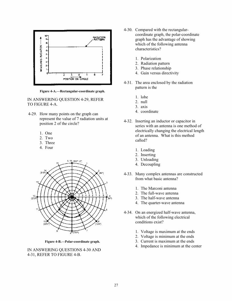
27
Figure 4-A.—Rectangular-coordinate graph.
IN ANSWERING QUESTION 4-29, REFER TO FIGURE 4-A. 4-29. How many points on the graph can
represent the value of 7 radiation units at position 2 of the circle?
1. One 2. Two 3. Three 4. Four
Figure 4-B.—Polar-coordinate graph.
IN ANSWERING QUESTIONS 4-30 AND 4-31, REFER TO FIGURE 4-B.
4-30. Compared with the rectangular-coordinate graph, the polar-coordinate graph has the advantage of showing which of the following antenna characteristics?
1. Polarization 2. Radiation pattern 3. Phase relationship 4. Gain versus directivity
4-31. The area enclosed by the radiation pattern is the
1. lobe 2. null 3. axis 4. coordinate
4-32. Inserting an inductor or capacitor in series with an antenna is one method of electrically changing the electrical length of an antenna. What is this method called?
1. Loading 2. Inserting 3. Unloading 4. Decoupling
4-33. Many complex antennas are constructed
from what basic antenna?
1. The Marconi antenna 2. The full-wave antenna 3. The half-wave antenna 4. The quarter-wave antenna
4-34. On an energized half-wave antenna, which of the following electrical conditions exist?
1. Voltage is maximum at the ends 2. Voltage is minimum at the ends 3. Current is maximum at the ends 4. Impedance is minimum at the center
28
4-35. Which of the following radiation patterns is/are exhibited by a simple vertical doublet antenna?
1. Nondirectional in the horizontal plane 2. Directional in the vertical plane 3. Both 1 and 2 above 4. Spherical in all planes
4-36. A method of feeding energy to a half-wave antenna is to connect one end through a capacitor to the output stage. What is this method of feeding called?
1. End feed 2. Voltage feed 3. Both 1 and 2 above 4. Current feed
4-37. An antenna supplied by the center-feed method is fed at what point?
1. Low voltage and low current 2. Low voltage and high current 3. High voltage and low current 4. High voltage and high current
4-38. The basic Marconi antenna has which of
the following characteristics?
1. One-quarter wavelength and ungrounded
2. One-half wavelength and grounded at one end
3. One-half wavelength and insulated from ground
4. One-quarter wavelength and grounded at one end
4-39. The Marconi antenna behaves as a dipole
for which of the following reasons?
1. It is fed at one end 2. An image antenna is formed by
reflections from the ground 3. A quarter-wavelength of conductor is
buried in the ground and forms the rest of the dipole
4. The applied signal is rectified so that only half the signal will appear on the quarter-wave antenna
4-40. A series of conductors arranged in a radial pattern and buried in the ground beneath the antenna is referred to as a
1. ground spur 2. counterpoise 3. ground screen 4. ground reflector
4-41. A folded dipole can be used instead of a simple, center-fed dipole for which of the following purposes?
1. Matching voltage 2. Matching impedance 3. Increasing directivity 4. Decreasing directivity
4-42. An antenna arrangement that has elements aligned in a straight line is referred to as what type array?
1. Isotropic 2. Collinear 3. Line-of-sight 4. Unidirectional
4-43. To have current in two adjoining
collinear half-wave elements in proper phase, they must be connected by which of the following stubs?
1. A shorted half-wave stub 2. An open quarter-wave stub 3. A shorted eighth-wave stub 4. A shorted quarter-wave stub
4-44. To select a desired signal and discriminate against interfering signals, the receiving antenna should have which of the following characteristics?
1. Be omnidirectional 2. Be highly directional 3. Be vertically polarized 4. Be horizontally polarized
29
4-45. Adding more elements to a collinear antenna array produces which of the following effects?
1. Increased gain 2. Decreased gain 3. Decreased directivity 4. Mismatched impedances
4-46. What is the maximum number of elements ordinarily used in a collinear array?
1. One 2. Two 3. Three 4. Four
4-47. Constructing a collinear array with elements longer than 1/2 wavelength has which of the following effects on antenna characteristics?
1. Increased gain 2. Decreased gain 3. Increased frequency range 4. Decreased frequency range
4-48. In a two-element collinear array,
maximum gain is obtained when the center-to-center spacing between the ends of the elements is approximately what electrical distance?
1. Wavelength 2. 0.15 wavelength 3. 0.5 wavelength 4. 0.75 wavelength
4-49. Compared with collinear arrays, broadside arrays have which of the following advantages?
1. Sharper tuning 2. Broader bandwidth 3. Broader frequency response 4. Less coupling between dipole
4-50. Optimum gain is obtained from a broadside array when the spacing of its elements is which of the following distances?
1. One-half wavelength 2. One-quarter wavelength 3. Greater than one-half wavelength 4. Slightly less than one-quarter
4-51. An end-fire array physically resembles the collinear array except that it is more compact. What disadvantage does the endfire array possess?
1. It has lower gain 2. It has low radiation resistance 3. It has loose coupling 4. Each of the above
4-52. What is the range of electrical spacing between the elements of an end-fire array?
1. 3/4 to 1 wavelength 2. 1/2 to 3/4 wavelength 3. 1/4 to 1/2 wavelength 4. 1/8 to 1/4 wavelength
4-53. The end-fire array produces what type of lobes, if any, along the axis of the array?
1. Minor lobes 2. Major lobes 3. None
4-54. Assuming that the elements are correctly spaced, the directivity of an end-fire array may be increased by which of the following actions?
1. Increasing the frequency 2. Decreasing the frequency 3. Decreasing the number of elements 4. Increasing the number of elements
30
4-55. A unidirectional pattern can be obtained from an end-fire array by using what phase relationship between the energy fed to adjacent elements?
1. 0º 2. 45º 3. 90º 4. 180º
4-56. Energy is fed to a parasitic element using what method?
1. Direct coupling 2. Inductive coupling 3. Capacitive coupling 4. Transmission-line coupling
4-57. The directivity pattern resulting from the action of parasitic elements depends on which of the following element characteristics?
1. Length of the element 2. Diameter of the element 3. Spacing between parasitic and driven
elements 4. Each of the above
4-58. The advantages of unidirectivity and increased gain can best be obtained by using which of the following elements in a parasitic array?
1. Driven elements only 2. Reflector and director elements only 3. Reflector, director, and driven
elements 4. Driven and director elements only
4-59. The ratio of energy radiated by an array in the principal direction of radiation to the energy radiated in the opposite direction describes which of the following relationships?
1. Side-to-side ratio 2. Front-to-back ratio 3. Driven-to-parasitic ratio 4. Reflector-to-director ratio
4-60. The Yagi antenna is an example of what type of antenna array?
1. Driven 2. End-fire 3. Multielement parasitic 4. Single-element parasitic
4-61. The addition of parasitic elements to the Yagi antenna has which of the following effects on antenna characteristics?
1. Increased gain 2. Narrower beam width 3. Narrower frequency response 4. Each of the above
4-62. An antenna which is designed especially for vertically-polarized ground waves at low frequencies is the
1. Yagi antenna 2. Marconi antenna 3. Beverage antenna 4. V antenna
4-63. What is the phase relationship of the signals that feed the V antenna?
1. 0º 2. 45º 3. 90º 4. 180º
4-64. A rhombic antenna is essentially a combination of which of the following antennas?
1. Two stacked long-wire radiators 2. Two V antennas placed side by side 3. Two collinear arrays in parallel 4. Four parallel half-wave radiators
4-65. A rhombic antenna has which of the following advantages?
1. Simple construction 2. Wide frequency range 3. Noncritical adjustment 4. Each of the above
31
4-66. The principal disadvantage of the rhombic antenna is its
1. poor directivity 2. large antenna site 3. low antenna voltage 4. high-frequency inefficiency
4-67. The unidirectional radiation pattern of the rhombic antenna is caused by which of the following antenna characteristics?
1. Size 2. Shape 3. Termination resistance 4. Frequency of the input energy
4-68. Horizontal half-wave antennas mounted at right angles to each other in the same horizontal plane make up which of the following antennas?
1. Rhombic 2. Flat-top 3. Turnstile 4. Ground-plane
4-69. The most common means of obtaining a
low-radiation angle from a vertical quarter-wave antenna is by what procedure?
1. Decreasing power 2. Increasing frequency 3. Adding a ground plane 4. Rotating the antenna to a horizontal
plane
4-70. A corner reflector antenna is used for which of the following purposes?
1. To decrease frequency range 2. To increase frequency range 3. To produce a unidirectional pattern 4. To produce an omnidirectional
pattern
4-71. If a corner-reflector antenna is horizontally polarized, its radiation pattern will take on what shape?
1. A narrow beam in the horizontal
plane 2. A narrow beam in the vertical plane 3. A beam similar to a half-wave dipole
in the horizontal plane 4. A beam similar to a half-wave dipole
with a reflector in the vertical plane
4-72. When radio or radar antennas are energized by transmitters, you must not go aloft until which of the following requirements are met?
1. A safety harness has been issued to
you 2. All transmitters are secured and
tagged 3. A working aloft "chit" has been filled
out and signed by proper authority 4. Each of the above