Embed Size (px)
Citation preview
DISTRIBUTION STATEMENT A: Approved for public release; distribution is unlimited.
NONRESIDENTTRAININGCOURSE
SEPTEMBER 1998
Navy Electricity andElectronics Training Series
Module 23—Magnetic Recording
NAVEDTRA 14195
DISTRIBUTION STATEMENT A: Approved for public release; distribution is unlimited.
Although the words “he,” “him,” and“his” are used sparingly in this course toenhance communication, they are notintended to be gender driven or to affront ordiscriminate against anyone.
i
PREFACE
By enrolling in this self-study course, you have demonstrated a desire to improve yourself and the Navy.Remember, however, this self-study course is only one part of the total Navy training program. Practicalexperience, schools, selected reading, and your desire to succeed are also necessary to successfully roundout a fully meaningful training program.
COURSE OVERVIEW : To introduce the student to the subject of Magnetic Recording who needs sucha background in accomplishing daily work and/or in preparing for further study.
THE COURSE: This self-study course is organized into subject matter areas, each containing learningobjectives to help you determine what you should learn along with text and illustrations to help youunderstand the information. The subject matter reflects day-to-day requirements and experiences ofpersonnel in the rating or skill area. It also reflects guidance provided by Enlisted Community Managers(ECMs) and other senior personnel, technical references, instructions, etc., and either the occupational ornaval standards, which are listed in theManual of Navy Enlisted Manpower Personnel Classificationsand Occupational Standards, NAVPERS 18068.
THE QUESTIONS: The questions that appear in this course are designed to help you understand thematerial in the text.
VALUE : In completing this course, you will improve your military and professional knowledge.Importantly, it can also help you study for the Navy-wide advancement in rate examination. If you arestudying and discover a reference in the text to another publication for further information, look it up.
1998 Edition Prepared byCTMC(SS) Milton Charles Georgo
Published byNAVAL EDUCATION AND TRAINING
PROFESSIONAL DEVELOPMENTAND TECHNOLOGY CENTER
NAVSUP Logistics Tracking Number0504-LP-026-8460

ii
Sailor’s Creed
“ I am a United States Sailor.
I will support and defend theConstitution of the United States ofAmerica and I will obey the ordersof those appointed over me.
I represent the fighting spirit of theNavy and those who have gonebefore me to defend freedom anddemocracy around the world.
I proudly serve my country’s Navycombat team with honor, courageand commitment.
I am committed to excellence andthe fair treatment of all.”
iii
TABLE OF CONTENTS
CHAPTER PAGE
1. Introduction to Magnetic Recording......................................................................... 1-1
2. Magnetic Tape.......................................................................................................... 2-1
3. Magnetic Tape Recorder Heads ............................................................................... 3-1
4. Magnetic Tape Recorder Transports ........................................................................ 4-1
5. Magnetic Tape Recorder Record and Reproduce Electronics.................................. 5-1
6. Magnetic Tape Recorder Specifications................................................................... 6-1
7. Digital Magnetic Tape Recording ............................................................................ 7-1
8. Magnetic Disk Recording......................................................................................... 8-1
APPENDIX
I. Glossary.................................................................................................................. AI-1
II. References .............................................................................................................. AII-1
INDEX ...................................................................................................................... INDEX-1
iv
CREDITS
The figures listed below and included in this edition of NEETS, Module 23, Magnetic Recording, were provided by Datatape, Inc. Permission to use these illustrations is gratefully acknowledged.
SOURCE FIGURE
Datatape, Inc. 3-2, 3-3, 3-4, 5-3, 6-3, 6-4 A&B, 7-1, 7-4, 7-5, 7-6
v
NAVY ELECTRICITY AND ELECTRONICS TRAININGSERIES
The Navy Electricity and Electronics Training Series (NEETS) was developed for use by personnel inmany electrical- and electronic-related Navy ratings. Written by, and with the advice of, seniortechnicians in these ratings, this series provides beginners with fundamental electrical and electronicconcepts through self-study. The presentation of this series is not oriented to any specific rating structure,but is divided into modules containing related information organized into traditional paths of instruction.
The series is designed to give small amounts of information that can be easily digested before advancingfurther into the more complex material. For a student just becoming acquainted with electricity orelectronics, it is highly recommended that the modules be studied in their suggested sequence. Whilethere is a listing of NEETS by module title, the following brief descriptions give a quick overview of howthe individual modules flow together.
Module 1, Introduction to Matter, Energy, and Direct Current, introduces the course with a short historyof electricity and electronics and proceeds into the characteristics of matter, energy, and direct current(dc). It also describes some of the general safety precautions and first-aid procedures that should becommon knowledge for a person working in the field of electricity. Related safety hints are locatedthroughout the rest of the series, as well.
Module 2, Introduction to Alternating Current and Transformers,is an introduction to alternating current(ac) and transformers, including basic ac theory and fundamentals of electromagnetism, inductance,capacitance, impedance, and transformers.
Module 3, Introduction to Circuit Protection, Control, and Measurement,encompasses circuit breakers,fuses, and current limiters used in circuit protection, as well as the theory and use of meters as electricalmeasuring devices.
Module 4, Introduction to Electrical Conductors, Wiring Techniques, and Schematic Reading,presentsconductor usage, insulation used as wire covering, splicing, termination of wiring, soldering, and readingelectrical wiring diagrams.
Module 5, Introduction to Generators and Motors,is an introduction to generators and motors, andcovers the uses of ac and dc generators and motors in the conversion of electrical and mechanicalenergies.
Module 6, Introduction to Electronic Emission, Tubes, and Power Supplies,ties the first five modulestogether in an introduction to vacuum tubes and vacuum-tube power supplies.
Module 7, Introduction to Solid-State Devices and Power Supplies,is similar to module 6, but it is inreference to solid-state devices.
Module 8, Introduction to Amplifiers,covers amplifiers.
Module 9, Introduction to Wave-Generation and Wave-Shaping Circuits,discusses wave generation andwave-shaping circuits.
Module 10, Introduction to Wave Propagation, Transmission Lines, and Antennas,presents thecharacteristics of wave propagation, transmission lines, and antennas.
vi
Module 11,Microwave Principles,explains microwave oscillators, amplifiers, and waveguides.
Module 12,Modulation Principles,discusses the principles of modulation.
Module 13, Introduction to Number Systems and Logic Circuits,presents the fundamental concepts ofnumber systems, Boolean algebra, and logic circuits, all of which pertain to digital computers.
Module 14, Introduction to Microelectronics,covers microelectronics technology and miniature andmicrominiature circuit repair.
Module 15, Principles of Synchros, Servos, and Gyros,provides the basic principles, operations,functions, and applications of synchro, servo, and gyro mechanisms.
Module 16, Introduction to Test Equipment,is an introduction to some of the more commonly used testequipments and their applications.
Module 17, Radio-Frequency Communications Principles,presents the fundamentals of a radio-frequency communications system.
Module 18,Radar Principles,covers the fundamentals of a radar system.
Module 19, The Technician's Handbook,is a handy reference of commonly used general information,such as electrical and electronic formulas, color coding, and naval supply system data.
Module 20,Master Glossary,is the glossary of terms for the series.
Module 21,Test Methods and Practices,describes basic test methods and practices.
Module 22, Introduction to Digital Computers,is an introduction to digital computers.
Module 23,Magnetic Recording,is an introduction to the use and maintenance of magnetic recorders andthe concepts of recording on magnetic tape and disks.
Module 24, Introduction to Fiber Optics,is an introduction to fiber optics.
Embedded questions are inserted throughout each module, except for modules 19 and 20, which arereference books. If you have any difficulty in answering any of the questions, restudy the applicablesection.
Although an attempt has been made to use simple language, various technical words and phrases havenecessarily been included. Specific terms are defined in Module 20,Master Glossary.
Considerable emphasis has been placed on illustrations to provide a maximum amount of information. Insome instances, a knowledge of basic algebra may be required.
Assignments are provided for each module, with the exceptions of Module 19,The Technician'sHandbook; and Module 20,Master Glossary. Course descriptions and ordering information are inNAVEDTRA 12061,Catalog of Nonresident Training Courses.
vii
Throughout the text of this course and while using technical manuals associated with the equipment youwill be working on, you will find the below notations at the end of some paragraphs. The notations areused to emphasize that safety hazards exist and care must be taken or observed.
WARNING
AN OPERATING PROCEDURE, PRACTICE, OR CONDITION, ETC., WHICH MAYRESULT IN INJURY OR DEATH IF NOT CAREFULLY OBSERVED ORFOLLOWED.
CAUTION
AN OPERATING PROCEDURE, PRACTICE, OR CONDITION, ETC., WHICH MAYRESULT IN DAMAGE TO EQUIPMENT IF NOT CAREFULLY OBSERVED ORFOLLOWED.
NOTE
An operating procedure, practice, or condition, etc., which is essential to emphasize.
viii
INSTRUCTIONS FOR TAKING THE COURSE
ASSIGNMENTS
The text pages that you are to study are listed atthe beginning of each assignment. Study thesepages carefully before attempting to answer thequestions. Pay close attention to tables andillustrations and read the learning objectives.The learning objectives state what you should beable to do after studying the material. Answeringthe questions correctly helps you accomplish theobjectives.
SELECTING YOUR ANSWERS
Read each question carefully, then select theBEST answer. You may refer freely to the text.The answers must be the result of your ownwork and decisions. You are prohibited fromreferring to or copying the answers of others andfrom giving answers to anyone else taking thecourse.
SUBMITTING YOUR ASSIGNMENTS
To have your assignments graded, you must beenrolled in the course with the NonresidentTraining Course Administration Branch at theNaval Education and Training ProfessionalDevelopment and Technology Center(NETPDTC). Following enrollment, there aretwo ways of having your assignments graded:(1) use the Internet to submit your assignmentsas you complete them, or (2) send all theassignments at one time by mail to NETPDTC.
Grading on the Internet: Advantages toInternet grading are:
• you may submit your answers as soon asyou complete an assignment, and
• you get your results faster; usually by thenext working day (approximately 24 hours).
In addition to receiving grade results for eachassignment, you will receive course completionconfirmation once you have completed all the
assignments. To submit your assignmentanswers via the Internet, go to:
https://courses.cnet.navy.mil
Grading by Mail: When you submit answersheets by mail, send all of your assignments atone time. Do NOT submit individual answersheets for grading. Mail all of your assignmentsin an envelope, which you either provideyourself or obtain from your nearest EducationalServices Officer (ESO). Submit answer sheetsto:
COMMANDING OFFICERNETPDTC N3316490 SAUFLEY FIELD ROADPENSACOLA FL 32559-5000
Answer Sheets: All courses include one“scannable” answer sheet for each assignment.These answer sheets are preprinted with yourSSN, name, assignment number, and coursenumber. Explanations for completing the answersheets are on the answer sheet.
Do not use answer sheet reproductions:Useonly the original answer sheets that weprovide—reproductions will not work with ourscanning equipment and cannot be processed.
Follow the instructions for marking youranswers on the answer sheet. Be sure that blocks1, 2, and 3 are filled in correctly. Thisinformation is necessary for your course to beproperly processed and for you to receive creditfor your work.
COMPLETION TIME
Courses must be completed within 12 monthsfrom the date of enrollment. This includes timerequired to resubmit failed assignments.
ix
PASS/FAIL ASSIGNMENT PROCEDURES
If your overall course score is 3.2 or higher, youwill pass the course and will not be required toresubmit assignments. Once your assignmentshave been graded you will receive coursecompletion confirmation.
If you receive less than a 3.2 on any assignmentand your overall course score is below 3.2, youwill be given the opportunity to resubmit failedassignments. You may resubmit failedassignments only once. Internet students willreceive notification when they have failed anassignment--they may then resubmit failedassignments on the web site. Internet studentsmay view and print results for failedassignments from the web site. Students whosubmit by mail will receive a failing result letterand a new answer sheet for resubmission of eachfailed assignment.
COMPLETION CONFIRMATION
After successfully completing this course, youwill receive a letter of completion.
ERRATA
Errata are used to correct minor errors or deleteobsolete information in a course. Errata mayalso be used to provide instructions to thestudent. If a course has an errata, it will beincluded as the first page(s) after the front cover.Errata for all courses can be accessed andviewed/downloaded at:
https://www.advancement.cnet.navy.mil
STUDENT FEEDBACK QUESTIONS
We value your suggestions, questions, andcriticisms on our courses. If you would like tocommunicate with us regarding this course, weencourage you, if possible, to use e-mail. If youwrite or fax, please use a copy of the StudentComment form that follows this page.
For subject matter questions:
E-mail: [email protected]: Comm: (850) 452-1001, ext. 1728
DSN: 922-1001, ext. 1728FAX: (850) 452-1370(Do not fax answer sheets.)
Address: COMMANDING OFFICERNETPDTC N3156490 SAUFLEY FIELD ROADPENSACOLA FL 32509-5237
For enrollment, shipping, grading, orcompletion letter questions
E-mail: [email protected]: Toll Free: 877-264-8583
Comm: (850) 452-1511/1181/1859DSN: 922-1511/1181/1859FAX: (850) 452-1370(Do not fax answer sheets.)
Address: COMMANDING OFFICERNETPDTC N3316490 SAUFLEY FIELD ROADPENSACOLA FL 32559-5000
NAVAL RESERVE RETIREMENT CREDIT
If you are a member of the Naval Reserve, youwill receive retirement points if you areauthorized to receive them under currentdirectives governing retirement of NavalReserve personnel. For Naval Reserveretirement, this course is evaluated at 2 points.(Refer to Administrative Procedures for NavalReservists on Inactive Duty,BUPERSINST1001.39, for more information about retirementpoints.)

x
THIS PAGE LEFT BLANK INTENTIONALLY.
xi
Student Comments
Course Title:NEETS Module 23Magnetic Recording
NAVEDTRA: 14195 Date:
We need some information about you:
Rate/Rank and Name: SSN: Command/Unit
Street Address: City: State/FPO: Zip
Your comments, suggestions, etc.:
Privacy Act Statement: Under authority of Title 5, USC 301, information regarding your military status isrequested in processing your comments and in preparing a reply. This information will not be divulged withoutwritten authorization to anyone other than those within DOD for official use in determining performance.
NETPDTC 1550/41 (Rev 4-00)

1-1
CHAPTER 1
INTRODUCTION TO MAGNETIC RECORDING
LEARNING OBJECTIVES
Learning objectives are stated at the beginning of each chapter. They serve as a preview of theinformation you are expected to learn in the chapter. The comprehension check questions placed withinthe text are based on the objectives. By successfully completing those questions and the associatedNRTC, you show that you have met the objectives and have learned the information. The learningobjectives for this chapter are listed below.
After completing this chapter, you will be able to do the following:
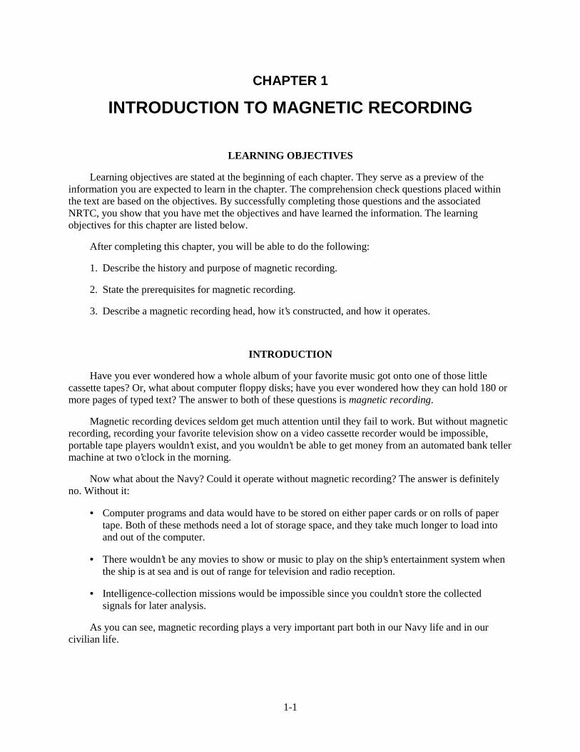
1. Describe the history and purpose of magnetic recording.
2. State the prerequisites for magnetic recording.
3. Describe a magnetic recording head, how it’s constructed, and how it operates.
INTRODUCTION
Have you ever wondered how a whole album of your favorite music got onto one of those littlecassette tapes? Or, what about computer floppy disks; have you ever wondered how they can hold 180 ormore pages of typed text? The answer to both of these questions is magnetic recording.
Magnetic recording devices seldom get much attention until they fail to work. But without magneticrecording, recording your favorite television show on a video cassette recorder would be impossible,portable tape players wouldn’t exist, and you wouldn’t be able to get money from an automated bank tellermachine at two o’clock in the morning.
Now what about the Navy? Could it operate without magnetic recording? The answer is definitelyno. Without it:
• Computer programs and data would have to be stored on either paper cards or on rolls of papertape. Both of these methods need a lot of storage space, and they take much longer to load intoand out of the computer.
• There wouldn’t be any movies to show or music to play on the ship’s entertainment system whenthe ship is at sea and is out of range for television and radio reception.
• Intelligence-collection missions would be impossible since you couldn’t store the collectedsignals for later analysis.
As you can see, magnetic recording plays a very important part both in our Navy life and in ourcivilian life.
1-2
HISTORY OF MAGNETIC RECORDERS
In 1888, Oberlin Smith originated the idea of using permanent magnetic impressions to recordsounds. Then in 1900, Vladeniar Poulsen brought Mr. Smith’s dream to reality. At the Paris Exposition,he demonstrated a Telegraphone. It was a device that recorded sounds onto a steel wire. Althougheveryone thought it was a great idea, they didn’t think it would succeed since you had to use an earphoneto hear what was recorded. It wasn’t until 1925, when electronic amplifiers were developed, that magneticrecording started to receive the attention it deserved.
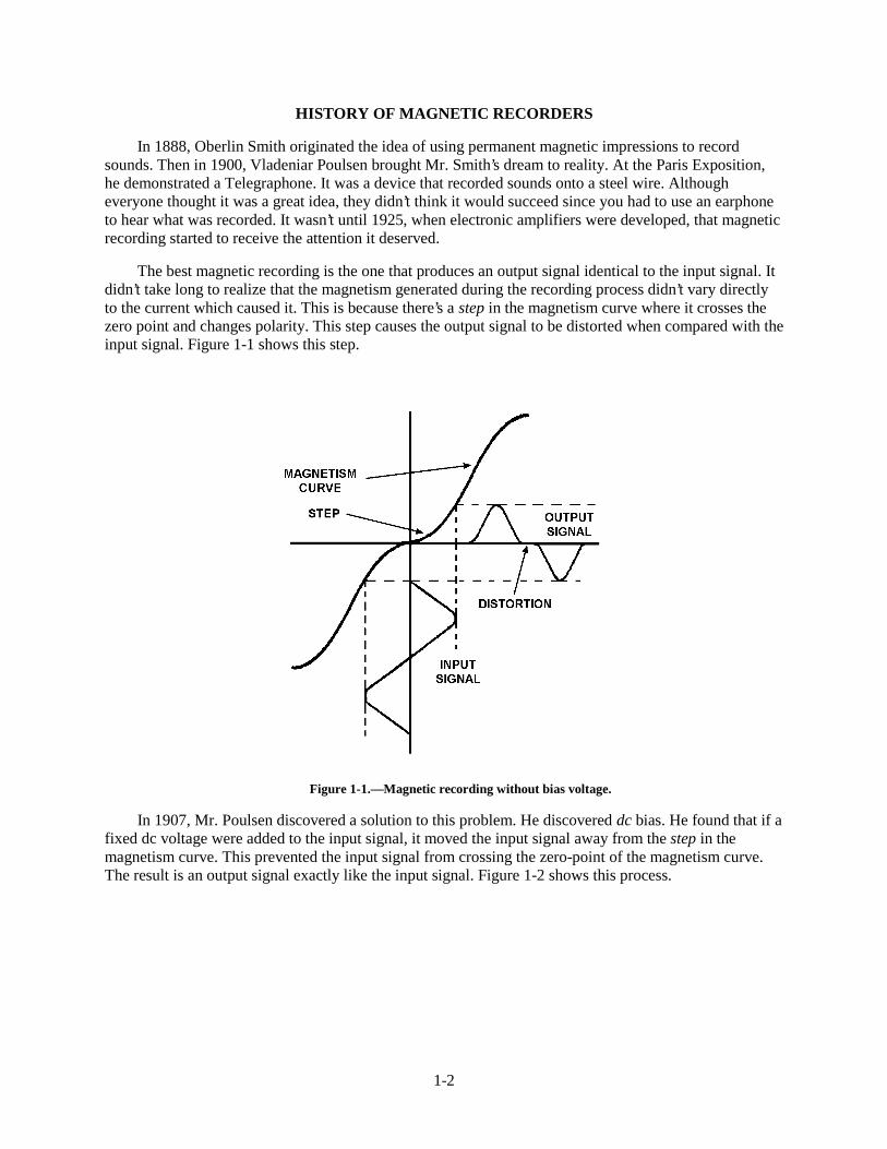
The best magnetic recording is the one that produces an output signal identical to the input signal. Itdidn’t take long to realize that the magnetism generated during the recording process didn’t vary directlyto the current which caused it. This is because there’s a step in the magnetism curve where it crosses thezero point and changes polarity. This step causes the output signal to be distorted when compared with theinput signal. Figure 1-1 shows this step.
Figure 1-1.—Magnetic recording without bias voltage.
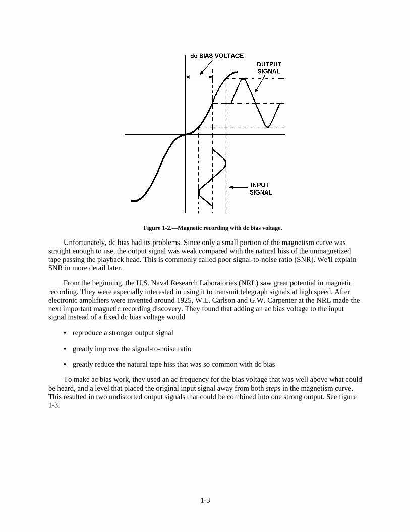
In 1907, Mr. Poulsen discovered a solution to this problem. He discovered dc bias. He found that if afixed dc voltage were added to the input signal, it moved the input signal away from the step in themagnetism curve. This prevented the input signal from crossing the zero-point of the magnetism curve.The result is an output signal exactly like the input signal. Figure 1-2 shows this process.
1-3
Figure 1-2.—Magnetic recording with dc bias voltage.
Unfortunately, dc bias had its problems. Since only a small portion of the magnetism curve wasstraight enough to use, the output signal was weak compared with the natural hiss of the unmagnetizedtape passing the playback head. This is commonly called poor signal-to-noise ratio (SNR). We’ll explainSNR in more detail later.
From the beginning, the U.S. Naval Research Laboratories (NRL) saw great potential in magneticrecording. They were especially interested in using it to transmit telegraph signals at high speed. Afterelectronic amplifiers were invented around 1925, W.L. Carlson and G.W. Carpenter at the NRL made thenext important magnetic recording discovery. They found that adding an ac bias voltage to the inputsignal instead of a fixed dc bias voltage would
• reproduce a stronger output signal
• greatly improve the signal-to-noise ratio
• greatly reduce the natural tape hiss that was so common with dc bias
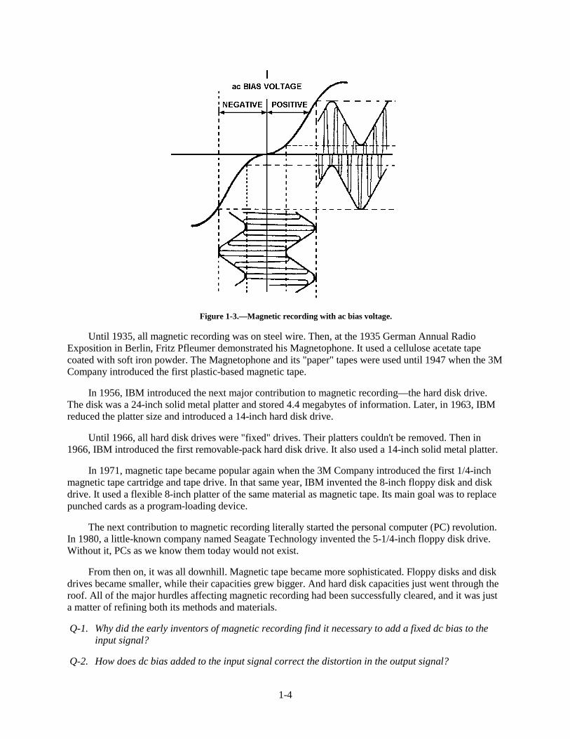
To make ac bias work, they used an ac frequency for the bias voltage that was well above what couldbe heard, and a level that placed the original input signal away from both steps in the magnetism curve.This resulted in two undistorted output signals that could be combined into one strong output. See figure1-3.
1-4
Figure 1-3.—Magnetic recording with ac bias voltage.
Until 1935, all magnetic recording was on steel wire. Then, at the 1935 German Annual RadioExposition in Berlin, Fritz Pfleumer demonstrated his Magnetophone. It used a cellulose acetate tapecoated with soft iron powder. The Magnetophone and its "paper" tapes were used until 1947 when the 3MCompany introduced the first plastic-based magnetic tape.
In 1956, IBM introduced the next major contribution to magnetic recording—the hard disk drive.The disk was a 24-inch solid metal platter and stored 4.4 megabytes of information. Later, in 1963, IBMreduced the platter size and introduced a 14-inch hard disk drive.
Until 1966, all hard disk drives were "fixed" drives. Their platters couldn't be removed. Then in1966, IBM introduced the first removable-pack hard disk drive. It also used a 14-inch solid metal platter.
In 1971, magnetic tape became popular again when the 3M Company introduced the first 1/4-inchmagnetic tape cartridge and tape drive. In that same year, IBM invented the 8-inch floppy disk and diskdrive. It used a flexible 8-inch platter of the same material as magnetic tape. Its main goal was to replacepunched cards as a program-loading device.
The next contribution to magnetic recording literally started the personal computer (PC) revolution.In 1980, a little-known company named Seagate Technology invented the 5-1/4-inch floppy disk drive.Without it, PCs as we know them today would not exist.
From then on, it was all downhill. Magnetic tape became more sophisticated. Floppy disks and diskdrives became smaller, while their capacities grew bigger. And hard disk capacities just went through theroof. All of the major hurdles affecting magnetic recording had been successfully cleared, and it was justa matter of refining both its methods and materials.
Q-1. Why did the early inventors of magnetic recording find it necessary to add a fixed dc bias to theinput signal?
Q-2. How does dc bias added to the input signal correct the distortion in the output signal?
1-5
Q-3. Why does adding dc vice ac bias voltage to the input signal result in a poor signal-to-noise ratio(SNR)?
Q-4. What are three advantages of adding an ac bias voltage to the input signal instead of adding afixed dc bias voltage?
Q-5. Why does using ac vice dc bias voltage result in a stronger output signal?
PREREQUISITES FOR MAGNETIC RECORDING
To perform magnetic recording, you need three things:
1. An input signal you wish to record.
2. A recording medium. (This is a recording surface that will hold the signal you wish to record.)
3. A magnetic head to convert the input signal into a magnetic field so it can be recorded.
If any one of these are missing, magnetic recording cannot take place.
Input Signal
An input signal can come from a microphone, a radio receiver, or any other source that’s capable ofproducing a recordable signal. Some input signals can be recorded immediately, but some must beprocessed first. This processing is needed when an input signal is weak, or is out of the frequencyresponse range of the recorder.
Recording Medium
A recording medium is any material that has the ability to become magnetized, in varying amounts,in small sections along its entire length. Some examples of this are magnetic tape and magnetic disks.These are thoroughly discussed in chapter 2 of this module.
Magnetic Heads
Magnetic heads are the heart of the magnetic recording process. They are the transducers thatconvert the electrical variations of your input signal into the magnetic variations that are stored on arecording medium. Without them, magnetic recording isn’t possible.
Magnetic heads actually do three different things. They transfer, or record, the signal informationonto the recording medium. They recover, or reproduce, the signal information from the recordingmedium. And they remove, or erase, the signal information from the recording medium.
MAGNETIC HEAD CONSTRUCTION.—A magnetic head is a magnetic core wrapped with acoil of very thin wire (see figure 1-4). The core material is usually shaped like the letter C, and is madefrom either iron or ceramic-ferrite material. The number of turns of wire placed on the core depends onthe purpose of that specific head. The gap in the core is called a head gap. It's here that magneticrecording actually takes place. We'll go into more detail of magnetic head construction in chapter 3.
1-6
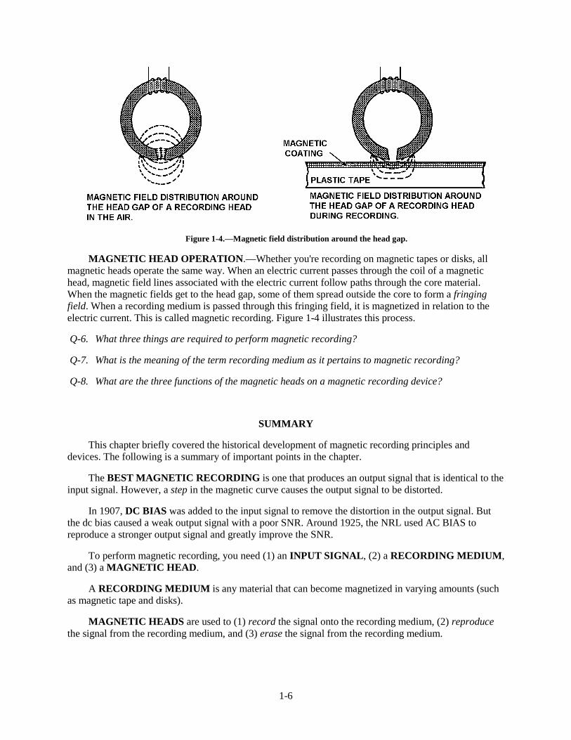
Figure 1-4.—Magnetic field distribution around the head gap.
MAGNETIC HEAD OPERATION.—Whether you're recording on magnetic tapes or disks, allmagnetic heads operate the same way. When an electric current passes through the coil of a magnetichead, magnetic field lines associated with the electric current follow paths through the core material.When the magnetic fields get to the head gap, some of them spread outside the core to form a fringingfield. When a recording medium is passed through this fringing field, it is magnetized in relation to theelectric current. This is called magnetic recording. Figure 1-4 illustrates this process.
Q-6. What three things are required to perform magnetic recording?
Q-7. What is the meaning of the term recording medium as it pertains to magnetic recording?
Q-8. What are the three functions of the magnetic heads on a magnetic recording device?
SUMMARY
This chapter briefly covered the historical development of magnetic recording principles anddevices. The following is a summary of important points in the chapter.
The BEST MAGNETIC RECORDING is one that produces an output signal that is identical to theinput signal. However, a step in the magnetic curve causes the output signal to be distorted.
In 1907, DC BIAS was added to the input signal to remove the distortion in the output signal. Butthe dc bias caused a weak output signal with a poor SNR. Around 1925, the NRL used AC BIAS toreproduce a stronger output signal and greatly improve the SNR.
To perform magnetic recording, you need (1) an INPUT SIGNAL, (2) a RECORDING MEDIUM,and (3) a MAGNETIC HEAD.
A RECORDING MEDIUM is any material that can become magnetized in varying amounts (suchas magnetic tape and disks).
MAGNETIC HEADS are used to (1) record the signal onto the recording medium, (2) reproducethe signal from the recording medium, and (3) erase the signal from the recording medium.
1-7
ANSWERS TO QUESTIONS Q1. THROUGH Q8.
A-1. Because a step in the magnetism curve where it crosses the zero point and changes polarity causesthe output signal to be distorted. See figure 1-1.
A-2. The dc bias moves the input signal away from the step in the magnetism curve. This prevents theinput signal from crossing the zero-point of the magnetism curve. See figure 1-2.
A-3. With dc bias, the SNR is poor because only a small portion of the magnetism curve is straightenough to use, thus the output signal is weak compared with the natural tape hiss.
A-4.
a. Reproduces a stronger output signal.
b. Greatly improves the SNR.
c. Greatly reduces the natural tape hiss.
A-5. Because an ac bias voltage of the proper frequency and level places the input signal away fromboth steps in the magnetism curve. The result is two undistorted output signals that are combinedinto one strong output.
A-6.
a. An input signal.
b. A recording medium.
c. A magnetic head.
A-7. A recording medium is any material that has the ability to become magnetized, in varying amounts,in small sections along its entire length.
A-8.
a. Record the signal onto the recording medium.
b. Reproduce the signal from the recording medium.
c. Erase the signal from the recording medium.

2-1
CHAPTER 2
MAGNETIC TAPE
LEARNING OBJECTIVES
After completing this chapter, you’ll be able to do the following:
1. Describe the physical properties of magnetic tape in terms of:
a. The Three Basic Materials Used To Make Magnetic Tape.
2. The function of the magnetic tape’s base material, oxide coating, and binder glue.
3. Describe the two types of magnetic recording tape.
4. Describe the following types of tape errors and their effects on magnetic tape recording: signaldropout, noise, skew, and level.
5. Describe the following causes of magnetic tape failure: normal wear, accidental damage,environmental damage, and winding errors.
6. Describe the purpose and makeup of tape reels and tape cartridges.
7. Describe the two methods for erasing magnetic tape, the characteristics of automatic and manualtape degaussers, and the procedures for degaussing magnetic tape.
8. Describe the proper procedures for handling, storing, and packaging magnetic tape, tape reels,and tape cartridges.
PHYSICAL PROPERTIES OF MAGNETIC TAPE
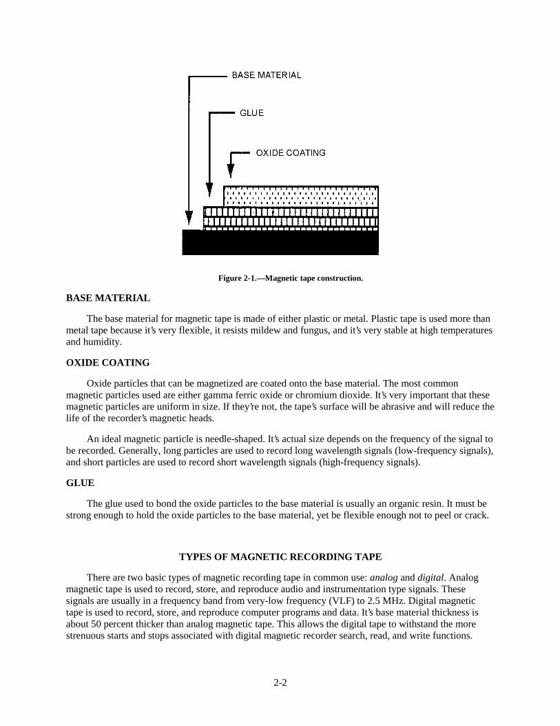
The three basic materials used to make magnetic tape are (1) the base material, (2) the coating ofmagnetic oxide particles, and (3) the glue to bind the oxide particles onto the base material. See figure2-1.
2-2
Figure 2-1.—Magnetic tape construction.
BASE MATERIAL
The base material for magnetic tape is made of either plastic or metal. Plastic tape is used more thanmetal tape because it’s very flexible, it resists mildew and fungus, and it’s very stable at high temperaturesand humidity.
OXIDE COATING
Oxide particles that can be magnetized are coated onto the base material. The most commonmagnetic particles used are either gamma ferric oxide or chromium dioxide. It’s very important that thesemagnetic particles are uniform in size. If they’re not, the tape’s surface will be abrasive and will reduce thelife of the recorder’s magnetic heads.
An ideal magnetic particle is needle-shaped. It’s actual size depends on the frequency of the signal tobe recorded. Generally, long particles are used to record long wavelength signals (low-frequency signals),and short particles are used to record short wavelength signals (high-frequency signals).
GLUE
The glue used to bond the oxide particles to the base material is usually an organic resin. It must bestrong enough to hold the oxide particles to the base material, yet be flexible enough not to peel or crack.
TYPES OF MAGNETIC RECORDING TAPE
There are two basic types of magnetic recording tape in common use: analog and digital. Analogmagnetic tape is used to record, store, and reproduce audio and instrumentation type signals. Thesesignals are usually in a frequency band from very-low frequency (VLF) to 2.5 MHz. Digital magnetictape is used to record, store, and reproduce computer programs and data. It’s base material thickness isabout 50 percent thicker than analog magnetic tape. This allows the digital tape to withstand the morestrenuous starts and stops associated with digital magnetic recorder search, read, and write functions.
2-3
Digital magnetic tape is also held to much stricter quality control standards. It’s important not tohave any blemishes or coating flaws on the tape’s surface. Because, if you lost one digital data bit, yourcomputer program or data would be bad. In contrast, losing one microsecond of an analog signal is notnearly as critical.
Q-1. Magnetic tape is made of what three basic materials?
Q-2. Why is plastic magnetic tape used more than metal tape?
Q-3. Which of the two types of magnetic tape is used to record audio and instrumentation type signalsin the VLF to 2.5MHz frequency range?
Q-4. What type of magnetic tape is used to record computer programs and data, and what are theadditional thickness and quality standards for this type of tape?
TAPE ERRORS AND THEIR EFFECTS
Four types of tape errors that will degrade the performance of a magnetic recording system are signaldropout, noise, skew, and level (signal amplitude changes).
DROPOUT ERRORS
Signal dropout is the most common and the most serious type of tape error. It’s a temporary, sharpdrop (50% or more) in signal strength caused by either contaminates on the magnetic tape or by missingoxide coating on part of the tape.
During recording and playback, the oxide particles on the tape can flake off and stick to therecorder’s guides, rollers, and heads. After collecting for awhile, the oxide deposits (now oxide lumps)break loose and stick to the magnetic tape. As the tape with the lumps passes over the head, the lumps getbetween the tape and the head and lift the tape away from the head. This causes the signal dropouts.Although oxide lumps cause most signal dropouts, remember that any contaminate (such as dust, lint oroil) that gets between the tape and the head can cause signal dropouts.
NOISE ERRORS
Noise errors are unwanted signals that appear when no signal should appear. They’re usually causedby a cut or a scratch on the magnetic tape. It’s the lack of oxide particles at the cut or the scratch thatcauses the noise error.
SKEW ERRORS
Skew errors only occur on multi-track magnetic tape recorders. The term skew describes the timedifferences that occur between individual tracks of a single magnetic head when the multi-track tape isn’tproperly aligned with the magnetic head.
There are two types of skew errors: fixed and dynamic. Fixed skew happens when properly alignedmagnetic tape passes an improperly aligned magnetic head. Dynamic skew happens when misaligned tapepasses a properly aligned head. This type of skew is usually caused by one or more of the following:
• A misaligned or worn-out tape transport system.
• A stretched or warped magnetic tape.
2-4
• A magnetic tape that is improperly wound on a reel.
LEVEL ERRORS
Magnetic tape is manufactured to have a specified output signal level (plus or minus some degree oferror). Level errors happen when the actual output signal level either drops or rises to a level outside theexpected range. For example, if a magnetic tape is rated for 10 volts ( +/−10%), any output signal levelbelow 9 volts or above 11 volts is a level error. Level errors are caused by an uneven oxide coating on themagnetic tape. This can come from either the original manufacturing process or from normal wear andtear.
Some causes of level errors are permanent and cannot be removed by any means. For example, acrease in the tape, a hole in the oxide, or a damaged edge. Other causes of level errors are removable andmay be cleaned off the tape. For example, oxide flakes or clumps, metallic particles, or dirt areremovable.
Q-5. What are four types of tape errors that can degrade a magnetic recording system’s performance?
Q-6. What are signal dropouts, and what are two tape defects that can cause signal dropouts?
Q-7. What is the most common and most serious type of signal dropout?
Q-8. You see a build-up of dust and lint on the take-up reel of a tape recorder. This can cause which ofthe four types of tape errors?
Q-9. What type of tape error causes noise to appear on the tape when no signal should appear? Whatcauses this type of tape error?
Q-10. The multi-track tape recorder in your computer system has a fixed skew error. What does thismean and what is the probable cause?
Q-11. Some tapes you are using may have level errors. What does this mean and what is the cause?
CAUSES OF MAGNETIC TAPE FAILURE
Tape failure happens when a magnetic tape’s performance degrades to a point where it’s no longerusable. The exact point where failure occurs will vary, depending on the type of tape and how it is used.
There are four main causes for tape failure:
1. Normal wear (natural causes)
2. Accidental damage
3. Environmental damage
4. Winding errors
NORMAL WEAR
Normal wear occurs because the tape must come in contact with fixed surfaces, such as a recorder’smagnetic heads, rollers, and guides. Over time, this repeated contact with the fixed surfaces causesexcessive dropout errors and makes the tape unusable.
2-5
ACCIDENTAL DAMAGE
Accidental tape damage that causes tape failure is any damage that wouldn’t normally occur underideal operating and handling conditions. It can be caused by either a human operator or the tape recorderitself. Accidental tape damage caused by human operators can range from accidentally dropping a reel ofmagnetic tape to improperly threading a magnetic tape recorder. Accidental tape damage caused byrecording equipment can occur if the recorder is poorly designed or if the tape transport mechanism isadjusted improperly.
ENVIRONMENTAL DAMAGE
The negative effect of environmental extremes on tape can also cause tape failure. Magnetic tape isvery flexible and can be used in a wide range of environmental conditions. It’s designed for use in atemperature range of about 2 to 130 degrees Fahrenheit (−20 to 55 degrees Celsius), and in a relativehumidity range of about 10 to 95%. Of course, these numbers are the extreme. Ideally, magnetic tapeshould be used and stored at a temperature of about 60 to 80º F (room temperature), and in a relativehumidity of about 40 to 60%.
Large changes from the ideal relative humidity cause tape to expand or contract and thus affect theuniformity of a tape's oxide coating. High relative humidity causes the tape to stretch and increases thetape's friction. The increased friction causes increased head wear, head clog by oxide particles, andhead-to-tape sticking. Low relative humidity encourages oxide shedding and increases static build-up ontape surfaces, causing the tape to collect airborne contaminants.
The effects of exceeding the ideal temperature and humidity ranges described above can cause thefollowing environmental damage to magnetic tape: tape deformation, oxide shedding, head-to-tapesticking, layer-to-layer sticking, dirt build-up, and excessive tape and head wear.
Tape Deformation
Magnetic tapes are wound onto tape reels with tension applied. This tension causes great layer-to-layer pressure within the reel pack. Changes in temperature and humidity can cause the backing materialto expand or contract, creating even more pressure. All of this pressure causes the tape to becomedeformed or warped.
Oxide Shedding
At temperatures above 130º F, a tape's oxide coating tends to become soft. At temperatures below2º F, the oxide coating tends to be brittle. In both cases, the oxide coating will shed, flake off, orotherwise become separated from the base material. These free pieces of oxide will then stick to parts ofthe tape transport, to the magnetic heads, or back onto the tape and cause dropout or level errors.
Head-to-Tape Sticking
At higher temperatures, the tape binder glue can soften to the point where it will stick to therecorder's magnetic head. This head-to-tape sticking causes jerky tape motion.
Layer-to-Layer Adhesion
When reels of magnetic tape are stored at higher temperatures, the tape's binder glue may melt andcause the layers of tape to stick to one another. In very severe cases, layer-to-layer adhesion can separatethe oxide coating from the base material and completely destroy a tape.
2-6
Dirt Build-up
Dirt build-up happens when the relative humidity level is less than 10%. The low humidity causesstatic electricity that attracts dirt and dust which builds up on the magnetic tape and other parts of themagnetic tape recorder.
Excessive Tape and Head Wear
When the relative humidity is more than 95%, the high humidity causes increased friction as the tapepasses over the heads. This, in turn, causes excessive tape and head wear.
Q-12. What is tape failure?
Q-13. What are four main causes of tape failure?
Q-14. How does normal wear cause tape failure?
Q-15. Accidental damage to magnetic tape is normally caused by the tape recorder itself or by humanoperators of the recorder. What are three frequent causes of such accidental damage?
Q-16. Environmental damage to magnetic tape can occur when the tape is stored in an area thatexceeds what ideal temperature and humidity ranges?
Q-17. What six types of environmental damage can occur to tapes in storage when the idealtemperature and humidity ranges are exceeded?
Q-18. After using a tape that was stored in an area where temperatures exceeded 130º F you noticepieces of oxide sticking to the recorder's tape-transport mechanism, to its magnetic heads, andonto the tape. What is the probable cause of these symptoms?
Q-19. Your activity stores its magnetic tape in an area where the temperature is 100º F. What two typesof environmental damage could occur that would make these tapes unusable?
Q-20. When the relative humidity is below 10%, what happens to magnetic tape and parts of a taperecorder that could cause environmental damage?
Q-21. How does relative humidity over 95% cause excessive tape and head wear?
WINDING ERRORS
Winding errors are another cause of tape failure. They happen when improper winding practicescreate an excessive or uneven force as the tape is being wound onto a tape reel. The form taken by thetape after it is wound onto the reel is called the tape pack. Winding errors can cause a deformed tape packthat will prevent good head-to-tape contact.
In most cases, a deformed tape pack can be fixed simply by rewinding it onto another reel at theproper tension and at the right temperature and humidity. The four most common types of tape packdeformation are:
1. Cinching
2. Pack-slip
3. Spoking

2-7
4. Windowing
Cinching
Cinching happens when a tape reel is stopped too quickly. The sudden stop causes the outer layers ofmagnetic tape to continue to spin after the inner layers have stopped. This causes any loosely wound tapewithin the pack to unwind and pile up. Figure 2-2 shows an example of a cinched tape pack (note thecomplete foldover of one tape strand).
Figure 2-2.—Example of cinched tape pack.
Pack Slip
Pack slip happens when the tape is loosely wound on the reel and is exposed to excessive vibrationor too much heat. This causes the tape to shift (side-to-side), causing steps in the tape pack. When a tapereel with pack slip is used, the magnetic tape will unwind unevenly and rub against the sides of the tapereel or the recorder’s tape guides. This can damage the magnetic tape and cause oxide shedding. Figure2-3 shows an example of pack slip.
Figure 2-3.—Example of pack slip.

2-8
Spoking
Spoking happens when magnetic tape is wound onto the tape reel with the tension increasing towardthe end of the winding. The higher tension on the outside of the tape pack causes the inner pack to buckleand deform. Spoking is also caused by the uneven pressures created when a tape is wound on a reel thathas a distorted hub, or when the tape is wound over a small particle that is deposited on the hub. Figure2-4 shows a spoked tape pack.
Figure 2-4.—Example of spoked tape pack.
Windowing
Windows are voids or see-through air gaps in the tape winding. They happen when magnetic tape isloosely wound onto a tape reel, and especially when the loosely wound reel is later exposed to extremeheat or humidity. Figure 2-5 shows a windowed tape pack.
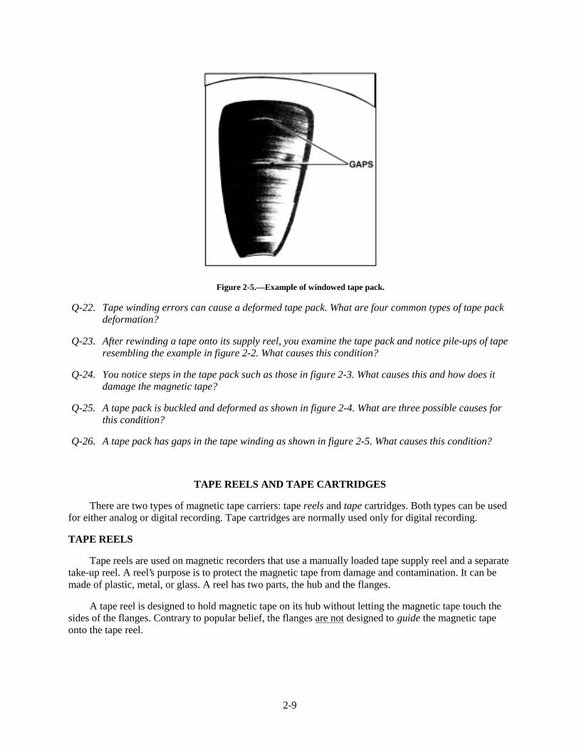
2-9
Figure 2-5.—Example of windowed tape pack.
Q-22. Tape winding errors can cause a deformed tape pack. What are four common types of tape packdeformation?
Q-23. After rewinding a tape onto its supply reel, you examine the tape pack and notice pile-ups of taperesembling the example in figure 2-2. What causes this condition?
Q-24. You notice steps in the tape pack such as those in figure 2-3. What causes this and how does itdamage the magnetic tape?
Q-25. A tape pack is buckled and deformed as shown in figure 2-4. What are three possible causes forthis condition?
Q-26. A tape pack has gaps in the tape winding as shown in figure 2-5. What causes this condition?
TAPE REELS AND TAPE CARTRIDGES
There are two types of magnetic tape carriers: tape reels and tape cartridges. Both types can be usedfor either analog or digital recording. Tape cartridges are normally used only for digital recording.
TAPE REELS
Tape reels are used on magnetic recorders that use a manually loaded tape supply reel and a separatetake-up reel. A reel’s purpose is to protect the magnetic tape from damage and contamination. It can bemade of plastic, metal, or glass. A reel has two parts, the hub and the flanges.
A tape reel is designed to hold magnetic tape on its hub without letting the magnetic tape touch thesides of the flanges. Contrary to popular belief, the flanges are not designed to guide the magnetic tapeonto the tape reel.
2-10
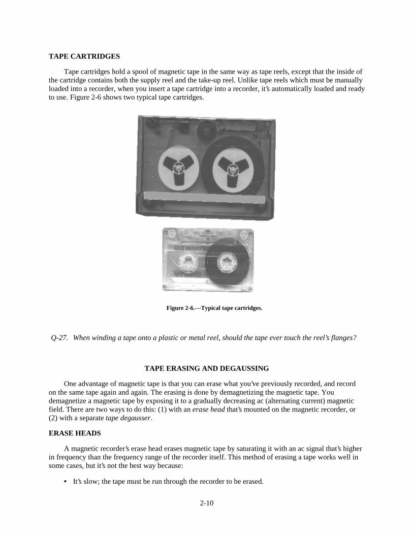
TAPE CARTRIDGES
Tape cartridges hold a spool of magnetic tape in the same way as tape reels, except that the inside ofthe cartridge contains both the supply reel and the take-up reel. Unlike tape reels which must be manuallyloaded into a recorder, when you insert a tape cartridge into a recorder, it’s automatically loaded and readyto use. Figure 2-6 shows two typical tape cartridges.
Figure 2-6.—Typical tape cartridges.
Q-27. When winding a tape onto a plastic or metal reel, should the tape ever touch the reel’s flanges?
TAPE ERASING AND DEGAUSSING
One advantage of magnetic tape is that you can erase what you’ve previously recorded, and recordon the same tape again and again. The erasing is done by demagnetizing the magnetic tape. Youdemagnetize a magnetic tape by exposing it to a gradually decreasing ac (alternating current) magneticfield. There are two ways to do this: (1) with an erase head that’s mounted on the magnetic recorder, or(2) with a separate tape degausser.
ERASE HEADS
A magnetic recorder’s erase head erases magnetic tape by saturating it with an ac signal that’s higherin frequency than the frequency range of the recorder itself. This method of erasing a tape works well insome cases, but it’s not the best way because:
• It’s slow; the tape must be run through the recorder to be erased.
2-11
• If the erase head is not completely demagnetized, it may not do a complete erasure.
• Some recorders do not have erase heads installed.
MAGNETIC TAPE DEGAUSSERS
By far, the best way to erase a magnetic tape is to use a separate magnetic tape degausser. There aretwo types of degaussers: automatic and manual.
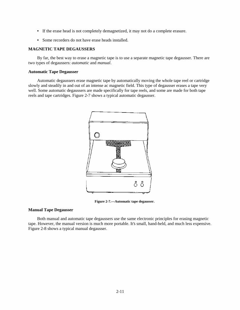
Automatic Tape Degausser
Automatic degaussers erase magnetic tape by automatically moving the whole tape reel or cartridgeslowly and steadily in and out of an intense ac magnetic field. This type of degausser erases a tape verywell. Some automatic degaussers are made specifically for tape reels, and some are made for both tapereels and tape cartridges. Figure 2-7 shows a typical automatic degausser.
Figure 2-7.—Automatic tape degausser.
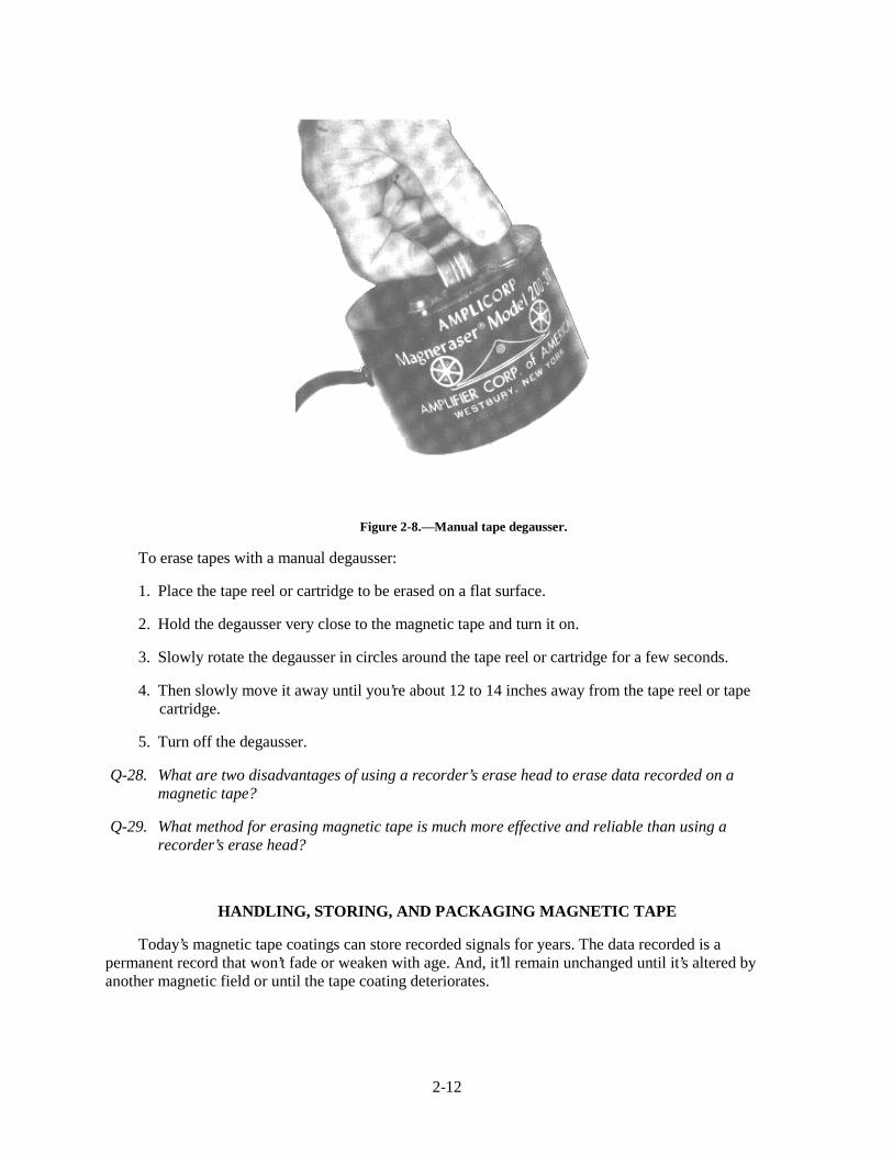
Manual Tape Degausser
Both manual and automatic tape degaussers use the same electronic principles for erasing magnetictape. However, the manual version is much more portable. It’s small, hand-held, and much less expensive.Figure 2-8 shows a typical manual degausser.
2-12
Figure 2-8.—Manual tape degausser.
To erase tapes with a manual degausser:
1. Place the tape reel or cartridge to be erased on a flat surface.
2. Hold the degausser very close to the magnetic tape and turn it on.
3. Slowly rotate the degausser in circles around the tape reel or cartridge for a few seconds.
4. Then slowly move it away until you’re about 12 to 14 inches away from the tape reel or tapecartridge.
5. Turn off the degausser.
Q-28. What are two disadvantages of using a recorder’s erase head to erase data recorded on amagnetic tape?
Q-29. What method for erasing magnetic tape is much more effective and reliable than using arecorder’s erase head?
HANDLING, STORING, AND PACKAGING MAGNETIC TAPE
Today’s magnetic tape coatings can store recorded signals for years. The data recorded is apermanent record that won’t fade or weaken with age. And, it’ll remain unchanged until it’s altered byanother magnetic field or until the tape coating deteriorates.
2-13
When magnetic tape recordings are ruined, the cause is usually poor handling, improper storage, orshipping damage. If you want your tape recordings to last a long time, you need to know how to properlyhandle, store, and ship magnetic tape.
HANDLING MAGNETIC TAPE
A magnetic tape reel or cartridge should always be in one of two places, either mounted on a taperecorder or in its storage container. When you handle magnetic tape, follow these rules:
• DO use extreme care when handling magnetic tape. Careless handling can damage magnetic tape,tape reels, and tape cartridges. Always hold a tape reel by the hub, NEVER by the flanges, andNEVER handle or touch the working tape surface.
• DO NOT let the magnetic tape trail on the floor. Even though the end of the tape may not havedata stored on it, it can pick up dirt and dust that ends up on the recorder.
• DO clean your hands before handling magnetic tape. You can contaminate magnetic tape withdirt and oils from dirty hands.
• DO mount tape reels and cartridges properly. Improperly seated tape reels can cause unnecessarywear and tear on the magnetic tape.
• DO replace any warped take-up reels, as they can damage magnetic tape.
• DO keep the magnetic recorder and its take-up reel clean. Magnetic tape can pick up dirt and dustfrom the recorder itself.
• DO NOT use the top of a magnetic recorder as a work area. This can expose the magnetic tape todirt, excessive heat, and stray magnetic fields.
• DO NOT allow eating, drinking, or smoking in areas where magnetic tape or devices are exposed.
STORING MAGNETIC TAPE
Most magnetic tape reels and cartridges spend a lot of time in storage. It’s very important that youprotect the stored tape from physical damage and the damaging effects of contamination and temperatureand humidity extremes. If you don’t, damage to the tape pack such as oxide shedding, layer-to-layersticking, and tape deformation can happen. To protect magnetic tape from damage during storage, followthese rules:
• DO make sure that magnetic tape is wound properly on the reel hub and at the proper tension.
• DO always store tape reels vertically. DO NOT lay them on their side.
• DO maintain a proper environment. Keep the storage area clean, and at a 60 to 80F degreetemperature and a 40 to 60% relative humidity.
• DO NOT store magnetic tapes near any equipment that generates stray magnetic fields.
• DO handle all tape reels and cartridges as gently as possible.
• DO NOT eat, drink, or smoke in a magnetic tape storage area.
2-14
PACKAGING MAGNETIC TAPE FOR SHIPPING
There may be times when you are asked to package magnetic tape reels or tape cartridges forshipment. If you want the tape to arrive in good condition, you must pack it properly to protect it fromdamage. The packaging you use must protect the tape reels or cartridges from impact, vibration, andtemperature and humidity changes. Here are some simple rules to follow:
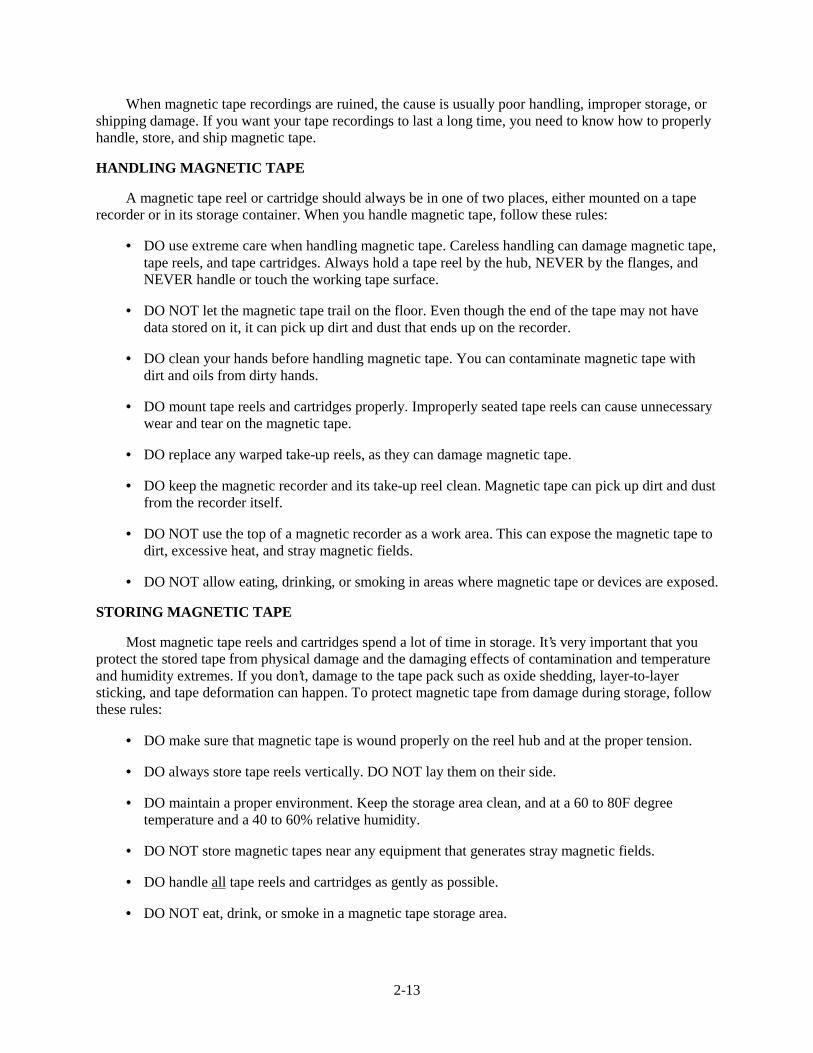
• DO always package tape reels so that they’re supported by their hub. This prevents any pressureon the reel’s flanges that might flex the flanges against the tape pack. Figure 2-9 shows a shippingbox that supports the tape reel by the hub.
Figure 2-9.—Reel box that supports reel by the hub.
• DO always use reel bands where available. Reel bands are for placement around the outside edgesof the reel flanges to help prevent the flanges from flexing and damaging the tape.
• DO always ship magnetic reels in a container designed so its normal positioning is with the reelsin a vertical position. This will prevent the tape pack from shifting and damaging the edges of themagnetic tape.
• DO always package tape cartridges in their shipping cases. Tape cartridges are more durable thantape reels, but they still need to be protected during shipment.
Q-30. When magnetic tapes are ruined, what three factors are normally the cause?
Q-31. What is the correct way to hold a magnetic tape reel?
Q-32. The take-up reel on your recorder is warped. What should you do to/with the reel?
Q-33. If magnetic tape is stored in areas with temperature and humidity extremes, what are three typesof tape damage that may occur?
Q-34. List four rules you should follow when storing magnetic tape to protect it from damage.
Q-35. When packaging tape reels or cartridges for shipping, what are four rules you should follow toprotect the tape reels from impact and vibration?
2-15
SUMMARY
Now that you’ve finished chapter 2, you should be able to (1) describe the physical properties ofmagnetic tape, (2) recognize the four most common magnetic tape errors, (3) recognize the four causes oftape failure, (4) describe the two methods for erasing magnetic tape, and (5) use the proper procedures forhandling, storing, and packaging magnetic tape, tape reels, and tape cartridges. The following is asummary of the important points in this chapter.
The three BASIC MATERIALS used to make magnetic tape are the (1) base material, (2) the oxideparticles, and (3) the binder glue.
ANALOG and DIGITAL are the two basic types of magnetic tape in common use.
BLEMISHES OR COATING FLAWS ON DIGITAL TAPE can easily ruin the data or thecomputer program stored on the tape.
SIGNAL DROPOUT, NOISE, SKEW, AND LEVEL are four types of tape errors. Dropout errorsare the most common.
OXIDE LUMPS accumulated on the tape cause most dropout errors. Other causes are dust or linton the tape, or missing oxide coating on part of the tape.
MAGNETIC TAPE FAILURE has four main causes: (1) normal wear, (2) accidental damage,(3) environmental damage, and (4) winding errors.
IDEAL TEMPERATURE AND HUMIDITY RANGES for using and storing magnetic tape are60 to 80º F and 40 to 60% relative humidity.
ENVIRONMENTAL TAPE DAMAGE caused by excessive temperature or humidity includes thefollowing: (1) tape deformation, (2) oxide shedding, (3) head-to-tape sticking, (4) layer-to-layer sticking,(5) dirt buildup, and (6) excessive tape and head wear.
WINDING ERRORS can cause tape pack deformation. The four most common types are:(1) cinching, (2) pack slip, (3) spoking, and (4) windowing.
The TWO PARTS OF A TAPE REEL are the hub and the flanges. The tape should be wound onthe hub. No part of the tape should be touching the flange sides.
ERASE HEADS AND TAPE DEGAUSSERS are two methods for erasing tape. Degaussers arethe fastest and the most reliable.
Rules for HANDLING MAGNETIC TAPE are (1) always hold the reel by the hub, not the flanges,(2) never touch the working tape surface, (3) replace warped or damaged reels, and (4) mount reels andcartridges properly.
Rules for STORING MAGNETIC TAPE are (1) wind tape properly on the reel hub, (2) store tapesvertically, (3) keep storage area clean and at proper temperature and humidity levels, and (4) store tapesaway from equipment that generates stray magnetic fields.
Rules for PACKAGING TAPE FOR SHIPPING are (1) support reels by their hubs, (2) use reelbands, (3) pack reels in containers vertically, and (4) keep tape cartridges in their shipping cases.
2-16
ANSWERS TO QUESTIONS Q1. THROUGH Q35.
A-1.
a. Base material.
b. Coating of magnetic oxide particles.
c. Glue that bonds the particles to the base.
A-2. Plastic tape is used more than metal because it’s more flexible, resists mildew and fungus, andis very stable at high temperatures and humidity.
A-3. Analog magnetic tape.
A-4. Digital magnetic tape is for computer programs and data. Its base material is about 50%thicker. The tape’s surface must not have blemishes or coating flaws because losing even onedigital data bit could ruin the recorded computer program or data.
A-5. Signal dropout, noise, skew, and level. Dropout is the most common.
A-6. Dropouts are temporary, sharp drops (50% or more) in signal strength. They’re caused bycontaminates that lift the tape away from the magnetic head, or when magnetic oxide coating ismissing on part of the tape.
A-7. Oxide particles that get onto the magnetic tape.
A-8. Signal dropout errors and level errors. The dust and lint on the reel will eventually get onto thetape where it can get between the tape and the recorder’s heads.
A-9. Noise error is usually caused by a cut or a scratch on the magnetic tape.
A-10. Skew means there are time differences between the individual tracks of a multi-track recorder’smagnetic head. It happens when the tape isn’t properly aligned with the head. Fixed skewhappens when the tape passes over an improperly aligned magnetic head.
A-11. The actual output signal level of the tape exceeds the manufacturer’s specified range for theoutput signal level (+ / − 10%). It’s caused by an uneven oxide coating on the tape due to worntape or defective manufacture.
A-12. Tape’s performance degrades to a point where it’s no longer usable.
A-13. Normal wear, accidental damage, environmental damage, and winding errors.
A-14. Repeated contact with a recorder’s fixed surfaces such as magnetic heads, tape rollers, and tapeguides.
A-15.
a. Improperly adjusted tape transport mechanism.
b. Dropping a reel of tape.
c. Improperly threading tape.

2-17
A-16. Ideally, use and store tape at 60 to 80º F and at 40 to 60% relative humidity.
A-17. Tape deformation, oxide shedding, head-to-tape sticking, layer-to-layer sticking, dirt build-up,and excessive tape and head wear.
A-18. Oxide shedding. At temperatures above 130º F, oxide coating becomes soft and sheds.
A-19. Head-to-tape sticking and layer-to-layer adhesion.
A-20. Dirt build-up caused by static electricity.
A-21. High humidity causes increased friction as the tape passes over the heads.
A-22. Cinching, pack slip, spoking, and windowing.
A-23. The tape is stopped too quickly when winding or rewinding.
A-24. Pack slip. It's caused by loosely wound tape on a reel that is exposed to excessive vibration orheat. The vibration or heat causes the tape to shift, causing steps in the tape pack. The uneventape will then rub against the reel's sides and the recorder's tape guides.
A-25.
a. Reel has a distorted hub,
b. tape wound over small particle deposited on hub, and
c. tape wound on reel with tension increasing toward end of winding.
A-26. Tape is loosely wound on reel.
A-27. No. The reel is designed to hold the tape on its hub without letting the tape touch the sides of theflanges.
A-28. Using an erase head is slow, and it may not completely erase the tape.
A-29. Using a magnetic tape degausser.
A-30. Poor handling, improper storage, or shipping damage.
A-31. Always hold reel by the hub, never by the flanges. Never touch the working tape surface.
A-32. Always replace a warped reel.
A-33. Oxide shedding, layer-to-layer sticking, and tape deformation.
A-34.
a. Make sure the tape is wound properly on the reel hub,
b. store tapes vertically,
c. keep storage area at right temperature and humidity,
d. store away from equipment that generates stray magnetic fields.

2-18
A-35.
a. Package reels so they’re supported by their hub,
b. use reel bands,
c. package reels in vertical position,
d. package tape cartridges in their shipping cases.
3-1
CHAPTER 3
MAGNETIC TAPE RECORDER HEADS
LEARNING OBJECTIVES
After completing this chapter, you'll be able to do the following:
1. Describe the construction, function, and placement of magnetic tape recorder record, reproduce, and erase heads.
2. Describe the preventive maintenance requirements for magnetic tape recorder heads.
MAGNETIC TAPE RECORDER HEADS
Magnetic tape recorder heads are the heart of magnetic tape recording, because it's the magnetic heads (as we'll call them in this chapter) that actually:
1. Record signal or data information onto magnetic tape
2. Reproduce (play back) signal or data information from magnetic tape
3. Erase any signal or data off of magnetic tape
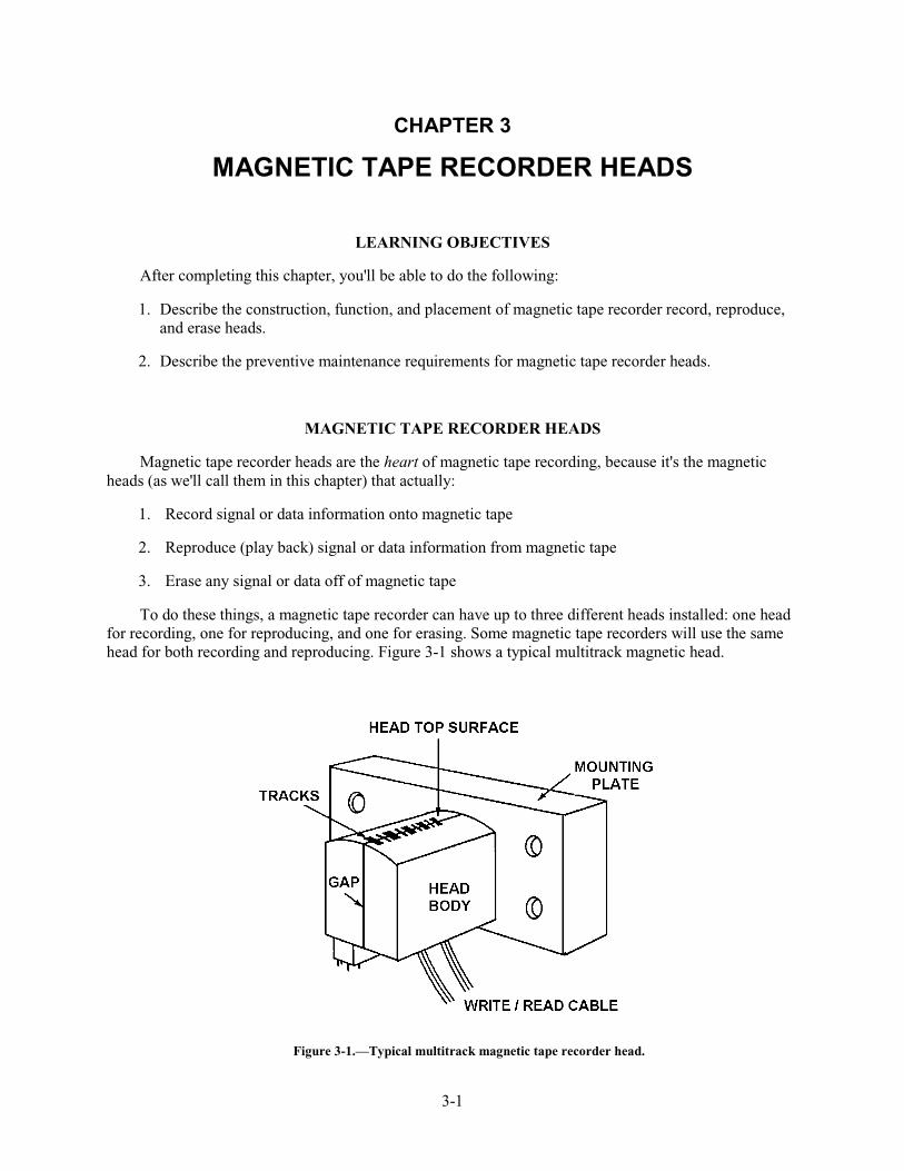
To do these things, a magnetic tape recorder can have up to three different heads installed: one head for recording, one for reproducing, and one for erasing. Some magnetic tape recorders will use the same head for both recording and reproducing. Figure 3-1 shows a typical multitrack magnetic head.
Figure 3-1.—Typical multitrack magnetic tape recorder head.
3-2
MAGNETIC HEAD CONSTRUCTION
Magnetic head construction is basically the same for all magnetic heads. They're all made up of a magnetic core wrapped with a coil of very thin wire. But, there's where the similarity ends. From here on, each magnetic head is built to perform a specific job. Will the head be used on a single track recorder? Will it be used on a multitrack recorder? Will it be a record head or a reproduce head? Or, will it be an erase head? What frequency will it be recording and/or reproducing? The answers to these questions will determine the final construction of a magnetic head.
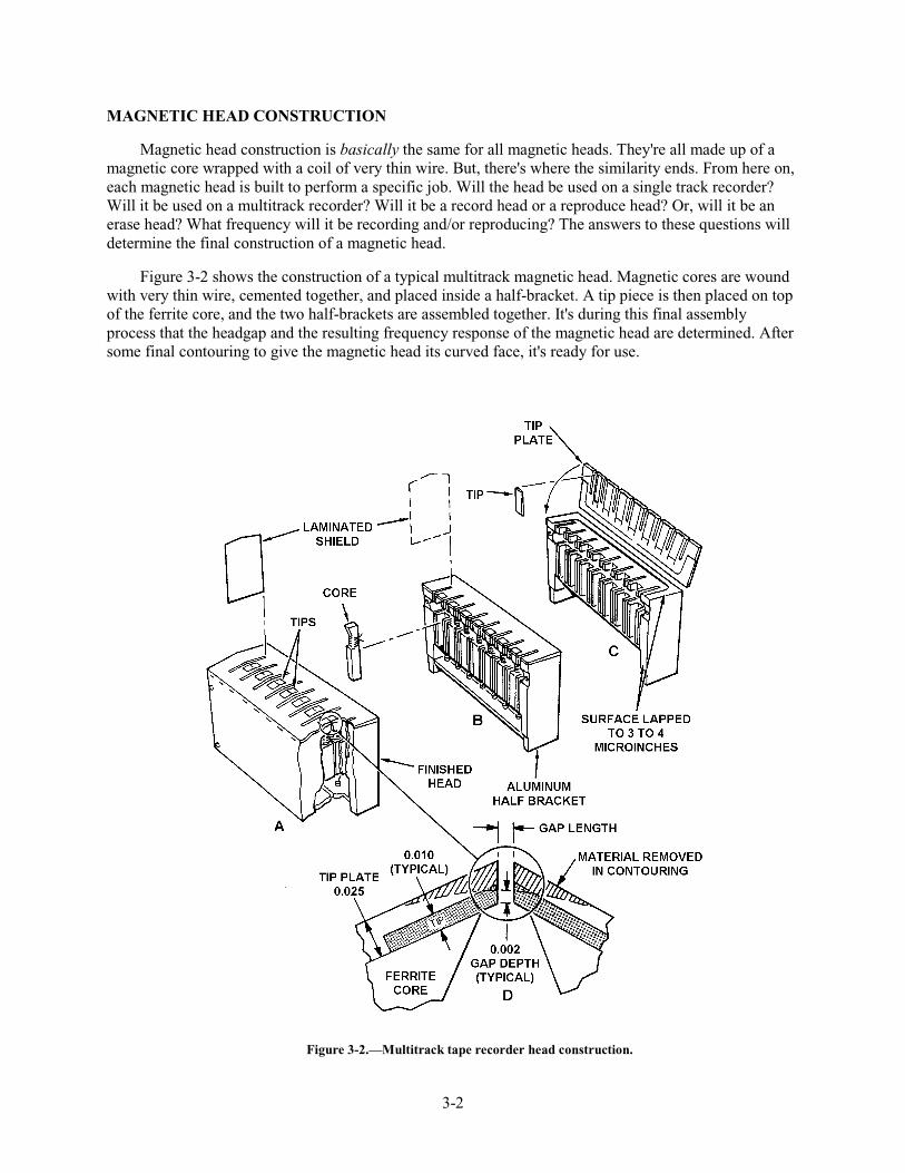
Figure 3-2 shows the construction of a typical multitrack magnetic head. Magnetic cores are wound with very thin wire, cemented together, and placed inside a half-bracket. A tip piece is then placed on top of the ferrite core, and the two half-brackets are assembled together. It's during this final assembly process that the headgap and the resulting frequency response of the magnetic head are determined. After some final contouring to give the magnetic head its curved face, it's ready for use.
Figure 3-2.—Multitrack tape recorder head construction.
3-3
Record and Reproduce Heads
Record and reproduce heads convert and transfer electrical signals onto and off of magnetic tape. The maximum frequency these heads can transfer depends on the size of the headgap and the speed of the magnetic tape (we'll discuss speed in the next chapter). Most record and reproduce heads are in one of these three general bandwidth categories:
1. Narrowband—100 Hz to 100 kHz
2. Intermediate band—100 Hz to 500 kHz
3. Wideband—400 Hz to 2 mHz
The only physical difference between a record head and a reproduce head is in the number of turns of wire on the core. A reproduce head will have more turns than a record head. This is because reproduce heads must be able to recover low-level signals from magnetic tape. The extra turns of wire allow the reproduce head to output the highest level possible and at a good signal-to-noise level.
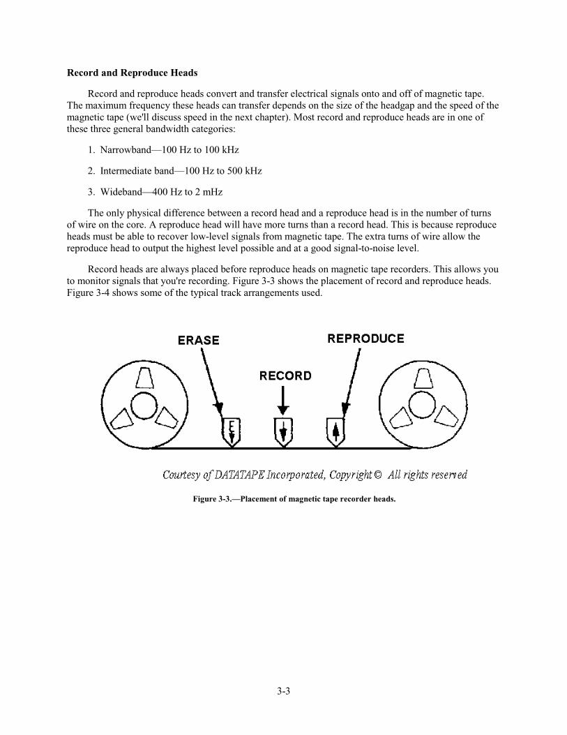
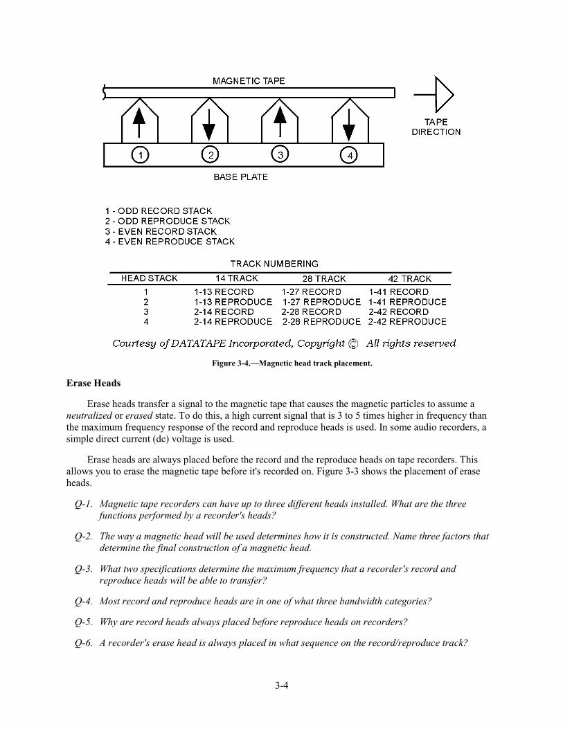
Record heads are always placed before reproduce heads on magnetic tape recorders. This allows you to monitor signals that you're recording. Figure 3-3 shows the placement of record and reproduce heads. Figure 3-4 shows some of the typical track arrangements used.
Figure 3-3.—Placement of magnetic tape recorder heads.
3-4
Figure 3-4.—Magnetic head track placement.
Erase Heads
Erase heads transfer a signal to the magnetic tape that causes the magnetic particles to assume a neutralized or erased state. To do this, a high current signal that is 3 to 5 times higher in frequency than the maximum frequency response of the record and reproduce heads is used. In some audio recorders, a simple direct current (dc) voltage is used.
Erase heads are always placed before the record and the reproduce heads on tape recorders. This allows you to erase the magnetic tape before it's recorded on. Figure 3-3 shows the placement of erase heads.
Q-1. Magnetic tape recorders can have up to three different heads installed. What are the three functions performed by a recorder's heads?
Q-2. The way a magnetic head will be used determines how it is constructed. Name three factors that determine the final construction of a magnetic head.
Q-3. What two specifications determine the maximum frequency that a recorder's record and reproduce heads will be able to transfer?
Q-4. Most record and reproduce heads are in one of what three bandwidth categories?
Q-5. Why are record heads always placed before reproduce heads on recorders?
Q-6. A recorder's erase head is always placed in what sequence on the record/reproduce track?
3-5
MAGNETIC HEAD MAINTENANCE
It's very important to regularly maintain magnetic heads. If you do, you'll greatly reduce the chance of getting a poor recording or playback. Regular preventive maintenance will also increase the life of the magnetic heads. There are two things you must do to properly maintain magnetic heads: (1) keep them clean, and (2) keep them demagnetized.
Cleaning Magnetic Heads
Through use, magnetic heads pick up dirt, dust, lint, and oxide particles from the magnetic tape. These particles collect on the magnetic head and, if left unchecked, could cause signal dropout errors that degrade the quality of recording and playback. To keep magnetic heads clean, regularly clean them with a cotton-tipped applicator soaked in either isopropyl alcohol or in a magnetic head cleaner recommended by the recorder's manufacturer. A good rule of thumb is to clean the heads each time you change a tape reel or cartridge.
Demagnetizing Magnetic Heads
Magnetic heads can become magnetized from many sources. It could happen
• during ac power losses,
• during testing or alignment,
• because of stray magnetic fields,
• from normal use.
No matter the cause, magnetized magnetic heads degrade the quality of the magnetic recording or playback.
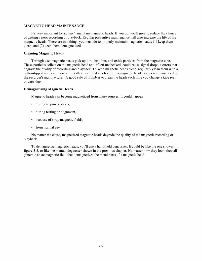
To demagnetize magnetic heads, you'll use a hand-held degausser. It could be like the one shown in figure 3-5, or like the manual degausser shown in the previous chapter. No matter how they look, they all generate an ac magnetic field that demagnetizes the metal parts of a magnetic head.
3-6
Figure 3-5.—Hand-held head degausser.
The procedure for demagnetizing a magnetic head is similar to the procedure for degaussing a magnetic tape. Here are the basic steps:
1. Remove the tape (reel or cartridge) from the magnetic recorder.
2. Holding the degausser an arm's length away from the magnetic head, energize the degausser.
3. Slowly bring the degausser closer and closer to the magnetic head. Don't touch the head with the degausser.
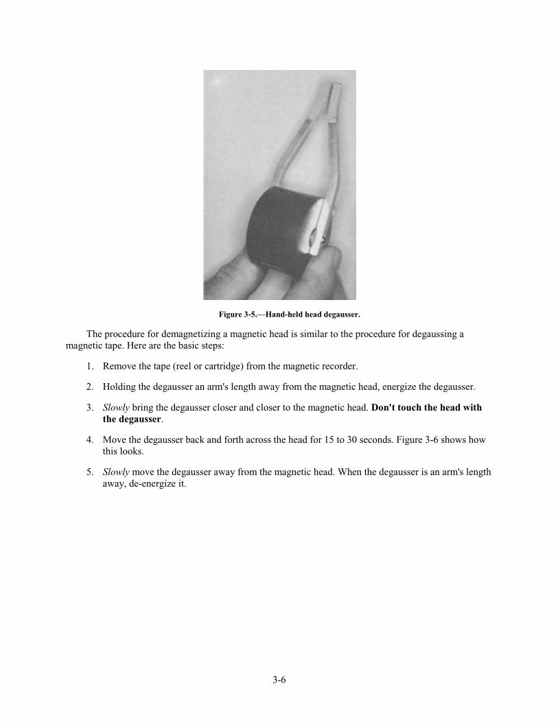
4. Move the degausser back and forth across the head for 15 to 30 seconds. Figure 3-6 shows how this looks.
5. Slowly move the degausser away from the magnetic head. When the degausser is an arm's length away, de-energize it.
3-7
Figure 3-6.—Demagnetizing magnetic heads with a degausser.
That's all there is to it. It's hard to determine exactly how often magnetic heads should be de-magnetized. Manufacturer's recommendations vary from every 8 to 25 hours of operation. To be safe, check the equipment's technical manual.
Q-7. What two preventive maintenance actions must you do regularly to increase magnetic head life and to ensure good tape recording and playback?
Q-8. How should you clean your recorder's magnetic heads?
Q-9. What are four sources that can cause magnetic heads to become magnetized?
Q-10. What type of equipment should you use to demagnetize your recorder's magnetic heads?
Q-11. How often should you demagnetize a recorder's magnetic heads?
SUMMARY
Now that you've finished chapter 3, you should be able to (1) describe the construction of magnetic tape recorder heads; (2) describe the purpose and placement of record, reproduce, and erase heads; and (3) describe the preventive maintenance requirements for tape recorder heads. The following is a summary of important points in this chapter:
Magnetic tape recorders have up to THREE MAGNETIC HEADS to perform the erase, record, or reproduce function.
Three factors that determine the CONSTRUCTION OF A MAGNETIC HEAD are the (1) type of head, (2) frequencies it will record, reproduce, or erase, and (3) use on a single or multitrack recorder.

3-8
Most tape recorder heads are designed for ONE OF THREE BANDWIDTHS: (1) narrowband, (2) intermediate band, or (3) wideband.
A recorder's magnetic heads are in the following SEQUENCE on its record/reproduce track: (1) erase, (2) record, and (3) reproduce.
Two important PREVENTIVE MAINTENANCE requirements for magnetic heads are cleaning and demagnetizing.
ANSWER TO QUESTIONS Q1. THROUGH Q11.
A-1. Record, reproduce, and erase.
A-2.
a. Type of head (record, reproduce, or erase).
b. Frequencies it will record or reproduce.
c. Whether it will be used on a single or multitrack recorder.
A-3.
a. Size of the headgap.
b. Speed of the magnetic tape.
A-4.
a. Narrowband—100 Hz to 100 kHz.
b. Intermediate band—100 Hz to 500 kHz.
c. Wideband—400 Hz to 2 mHz.
A-5. Allow you to monitor the signals you're recording.
A-6. First, before the record and reproduce heads.
A-7.
a. Keep the heads clean.
b. Keep the heads demagnetized.
A-8. With a cotton-tipped applicator soaked in either isopropyl alcohol or a head cleaner recommended by the recorder's manufacturer.
3-9
A-9.
a. During ac power losses.
b. During testing.
c. Because of stray magnetic fields.
d. From normal use.
A-10. A hand-held degausser like the manual degaussers used for degaussing magnetic tape.
A-11. Every 8 to 25 hours depending on the manufacturer's recommendations.

4-1
CHAPTER 4
MAGNETIC TAPE RECORDER TRANSPORTS
LEARNING OBJECTIVES
After completing this chapter, you'll be able to do the following:
1. Describe the function and components of a basic magnetic tape transport system.
2. Describe the operating characteristics and parts of the three most common tape reeling systems.
3. Describe the physical characteristics of the two basic tape reeling configurations, co-planar and co-axial.
4. Describe the characteristics of open-loop drive and closed-loop drive tape transport configurations and the three most common closed-loop designs.
5. Describe the capstan speed control function of a tape transport system and the relationship of the six basic parts of a typical capstan speed control unit.
6. Explain why, and describe how, magnetic tape transports must be cleaned and degaussed.
INTRODUCTION
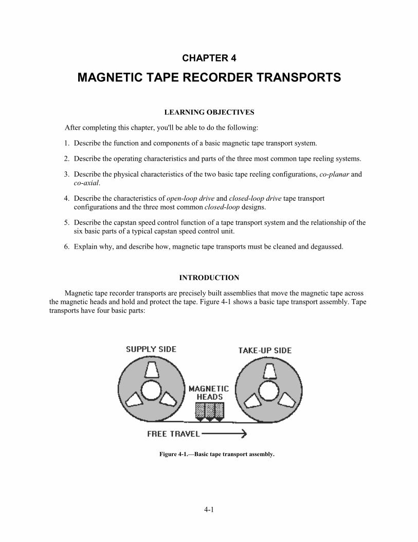
Magnetic tape recorder transports are precisely built assemblies that move the magnetic tape across the magnetic heads and hold and protect the tape. Figure 4-1 shows a basic tape transport assembly. Tape transports have four basic parts:
Figure 4-1.—Basic tape transport assembly.
4-2
1. A tape reeling system that, with the aid of tape guides, physically moves the tape across the magnetic heads.
2. A tape speed control system that monitors and controls the movement of the magnetic tape.
3. An electronic subsystem that activates the reeling device to move the magnetic tape.
4. A basic enclosure that holds and protects the reels or cartridges of magnetic tape.
This chapter describes these basic parts, tells how they work, and shows diagrams of the more common ones.
TAPE REELING SYSTEMS
A basic magnetic recorder tape reeling system (figure 4-1) has one supply reel and one take-up reel. Its job is to move the magnetic tape from one reel to the other. When this happens, four things occur:
1. The supply reel feeds out magnetic tape at a constant tension.
2. The tape passes the magnetic heads in a straight line.
3. The take-up reel accepts the magnetic tape at a constant tension.
4. Both the supply and take-up reels start and stop smoothly while maintaining the proper tape tension.
These four things must happen, or the magnetic tape could be damaged. Three of the most commonly used tape reeling systems are (1) take-up control, (2) two-motor reeling, and (3) tape buffering.
TAKE-UP CONTROL REELING SYSTEMS
This system uses a motorized take-up reel which pulls the magnetic tape off of a free-spooling supply reel. It maintains tape tension by using mechanical drag on the supply reel. As you might guess, this method has its disadvantages. It only works in one direction, and the tape tension doesn't remain constant throughout the reel. As the supply reel gives out tape, the tape tension varies. Uneven tape tension can cause stretched tape, poorly wound tape reels, and tape damage during starts and stops.
TWO-MOTOR REELING SYSTEMS
To overcome the problems of take-up control reeling systems, designers added a motor to the supply reel. By using two motors, the magnetic tape direction can be forward or reverse.
Two-motor reeling configurations usually use dc (direct current) motors, instead of ac (alternating current) motors, because dc motors run smoother and are easier to control. To help control tape tension, a small hold-back voltage is added to the motor for the supply reel.
Unfortunately, two-motor reeling systems do not properly control tape tension during starts and stops. Something called tape buffering must be added.
4-3
TAPE BUFFERING REELING SYSTEMS
Controlling a recorder's tape tension during starts and stops is a big problem. Tape buffering overcomes this problem by regulating the tape reel speed and by protecting against changes in tape tension.
Every manufacturer of high-quality, high performance magnetic tape recorders uses some sort of tape buffering. It's especially important in magnetic recorders that operate at many different speeds, where precise tape tension must be maintained.
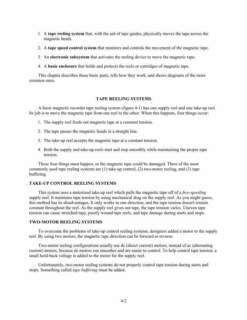
Figure 4-2 shows the relationship between the tape reeling system and the tape buffering system. As you can see, the speed at which a tape reel will give up or take up magnetic tape is controlled by its respective speed control servo. Feedback from the supply and take-up buffers tells the servo to speed up or slow down.
Figure 4-2.—Tape buffering arrangement.
There are two basic types of reeling system buffers: (1) spring-tension, and (2) vacuum-column.
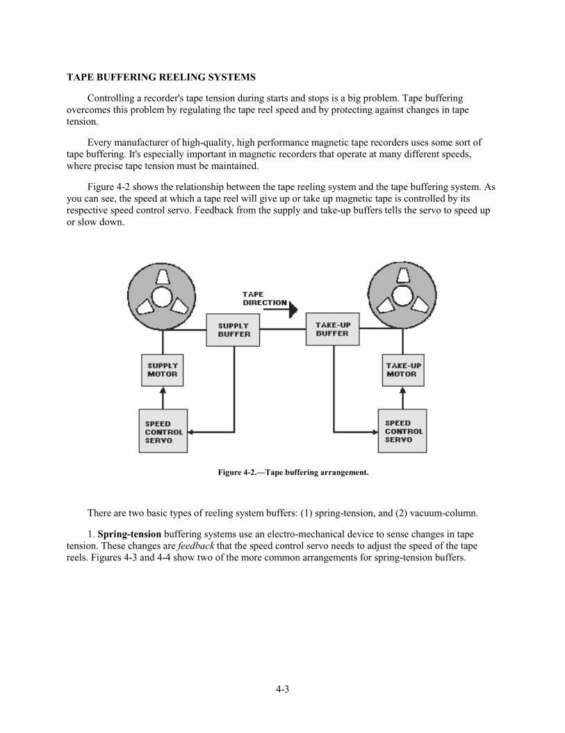
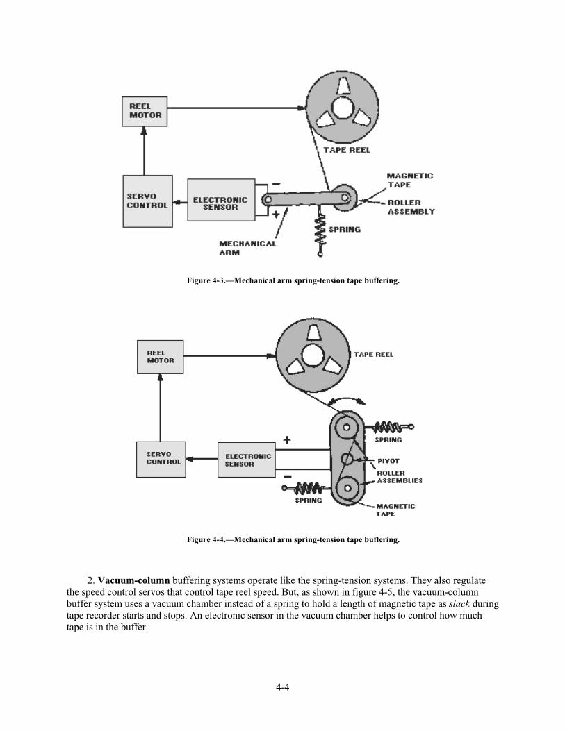
1. Spring-tension buffering systems use an electro-mechanical device to sense changes in tape tension. These changes are feedback that the speed control servo needs to adjust the speed of the tape reels. Figures 4-3 and 4-4 show two of the more common arrangements for spring-tension buffers.
4-4
Figure 4-3.—Mechanical arm spring-tension tape buffering.
Figure 4-4.—Mechanical arm spring-tension tape buffering.
2. Vacuum-column buffering systems operate like the spring-tension systems. They also regulate the speed control servos that control tape reel speed. But, as shown in figure 4-5, the vacuum-column buffer system uses a vacuum chamber instead of a spring to hold a length of magnetic tape as slack during tape recorder starts and stops. An electronic sensor in the vacuum chamber helps to control how much tape is in the buffer.
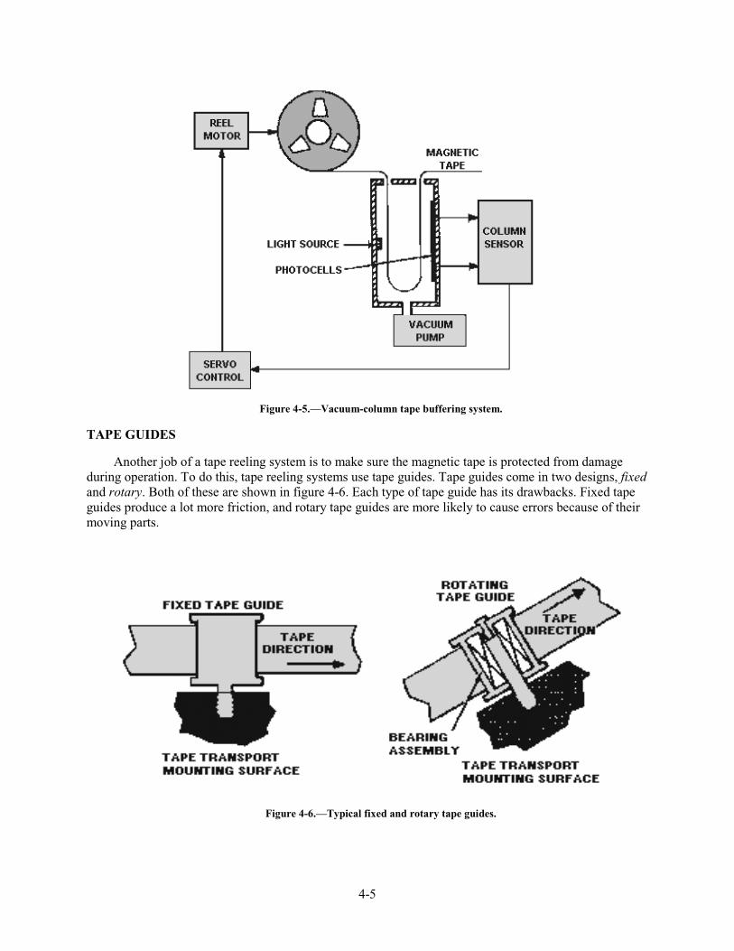
4-5
Figure 4-5.—Vacuum-column tape buffering system.
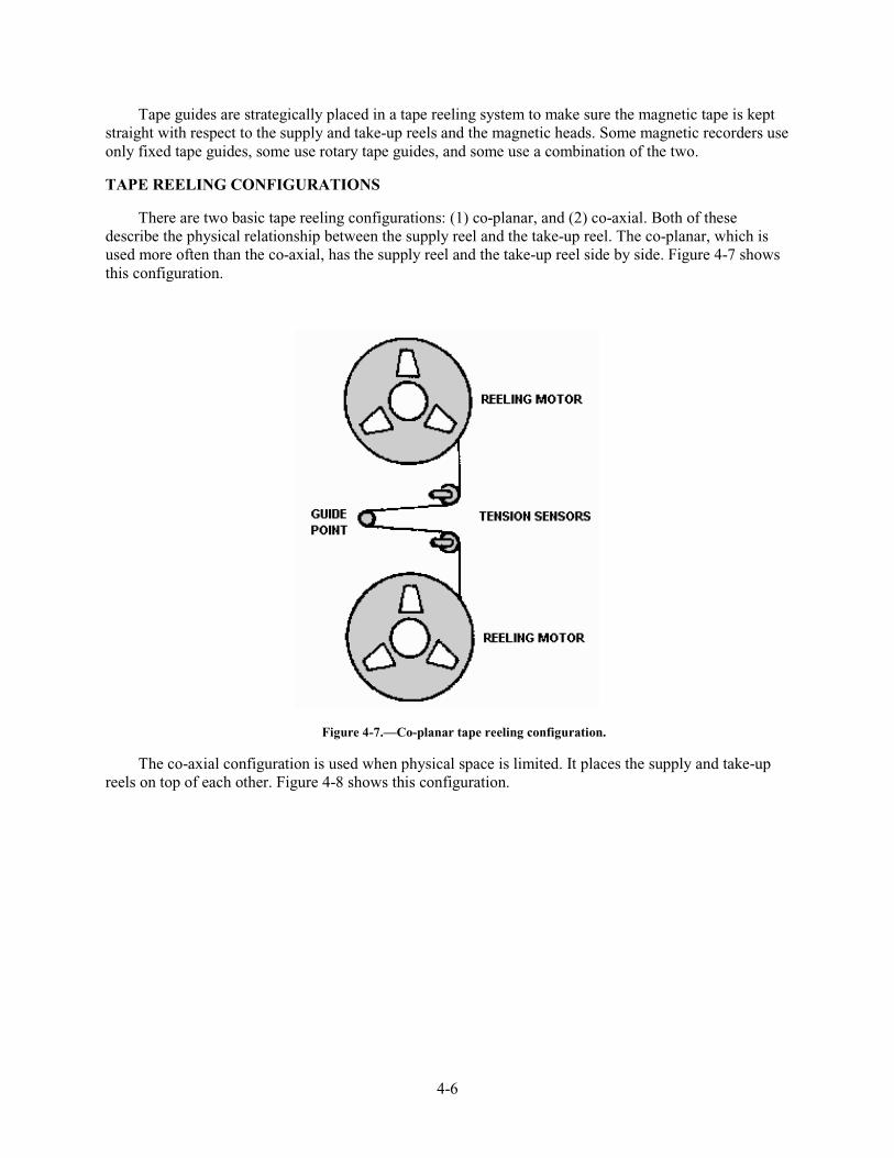
TAPE GUIDES
Another job of a tape reeling system is to make sure the magnetic tape is protected from damage during operation. To do this, tape reeling systems use tape guides. Tape guides come in two designs, fixed and rotary. Both of these are shown in figure 4-6. Each type of tape guide has its drawbacks. Fixed tape guides produce a lot more friction, and rotary tape guides are more likely to cause errors because of their moving parts.
Figure 4-6.—Typical fixed and rotary tape guides.
4-6
Tape guides are strategically placed in a tape reeling system to make sure the magnetic tape is kept straight with respect to the supply and take-up reels and the magnetic heads. Some magnetic recorders use only fixed tape guides, some use rotary tape guides, and some use a combination of the two.
TAPE REELING CONFIGURATIONS
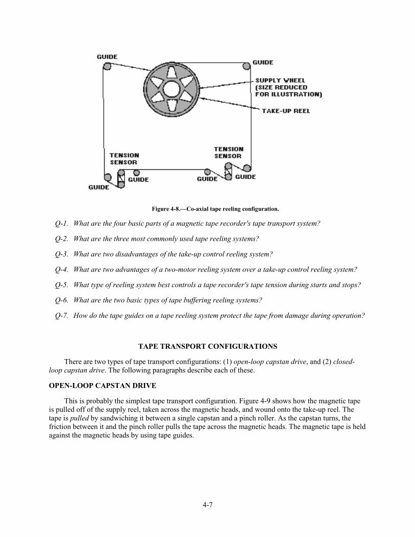
There are two basic tape reeling configurations: (1) co-planar, and (2) co-axial. Both of these describe the physical relationship between the supply reel and the take-up reel. The co-planar, which is used more often than the co-axial, has the supply reel and the take-up reel side by side. Figure 4-7 shows this configuration.
Figure 4-7.—Co-planar tape reeling configuration.
The co-axial configuration is used when physical space is limited. It places the supply and take-up reels on top of each other. Figure 4-8 shows this configuration.
4-7
Figure 4-8.—Co-axial tape reeling configuration.
Q-1. What are the four basic parts of a magnetic tape recorder's tape transport system?
Q-2. What are the three most commonly used tape reeling systems?
Q-3. What are two disadvantages of the take-up control reeling system?
Q-4. What are two advantages of a two-motor reeling system over a take-up control reeling system?
Q-5. What type of reeling system best controls a tape recorder's tape tension during starts and stops?
Q-6. What are the two basic types of tape buffering reeling systems?
Q-7. How do the tape guides on a tape reeling system protect the tape from damage during operation?
TAPE TRANSPORT CONFIGURATIONS
There are two types of tape transport configurations: (1) open-loop capstan drive, and (2) closed-loop capstan drive. The following paragraphs describe each of these.
OPEN-LOOP CAPSTAN DRIVE
This is probably the simplest tape transport configuration. Figure 4-9 shows how the magnetic tape is pulled off of the supply reel, taken across the magnetic heads, and wound onto the take-up reel. The tape is pulled by sandwiching it between a single capstan and a pinch roller. As the capstan turns, the friction between it and the pinch roller pulls the tape across the magnetic heads. The magnetic tape is held against the magnetic heads by using tape guides.
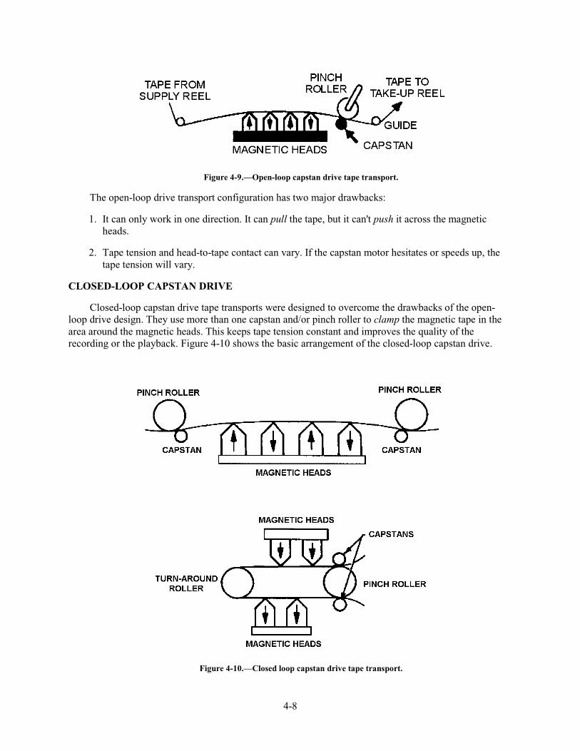
4-8
Figure 4-9.—Open-loop capstan drive tape transport.
The open-loop drive transport configuration has two major drawbacks:
1. It can only work in one direction. It can pull the tape, but it can't push it across the magnetic heads.
2. Tape tension and head-to-tape contact can vary. If the capstan motor hesitates or speeds up, the tape tension will vary.
CLOSED-LOOP CAPSTAN DRIVE
Closed-loop capstan drive tape transports were designed to overcome the drawbacks of the open-loop drive design. They use more than one capstan and/or pinch roller to clamp the magnetic tape in the area around the magnetic heads. This keeps tape tension constant and improves the quality of the recording or the playback. Figure 4-10 shows the basic arrangement of the closed-loop capstan drive.
Figure 4-10.—Closed loop capstan drive tape transport.
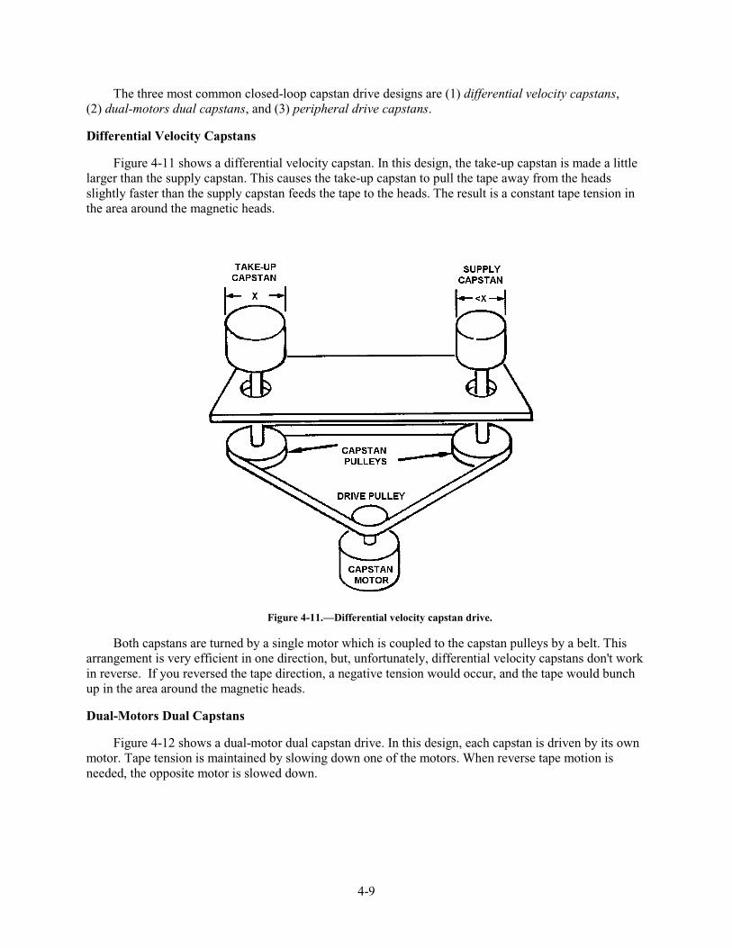
4-9
The three most common closed-loop capstan drive designs are (1) differential velocity capstans, (2) dual-motors dual capstans, and (3) peripheral drive capstans.
Differential Velocity Capstans
Figure 4-11 shows a differential velocity capstan. In this design, the take-up capstan is made a little larger than the supply capstan. This causes the take-up capstan to pull the tape away from the heads slightly faster than the supply capstan feeds the tape to the heads. The result is a constant tape tension in the area around the magnetic heads.
Figure 4-11.—Differential velocity capstan drive.
Both capstans are turned by a single motor which is coupled to the capstan pulleys by a belt. This arrangement is very efficient in one direction, but, unfortunately, differential velocity capstans don't work in reverse. If you reversed the tape direction, a negative tension would occur, and the tape would bunch up in the area around the magnetic heads.
Dual-Motors Dual Capstans
Figure 4-12 shows a dual-motor dual capstan drive. In this design, each capstan is driven by its own motor. Tape tension is maintained by slowing down one of the motors. When reverse tape motion is needed, the opposite motor is slowed down.
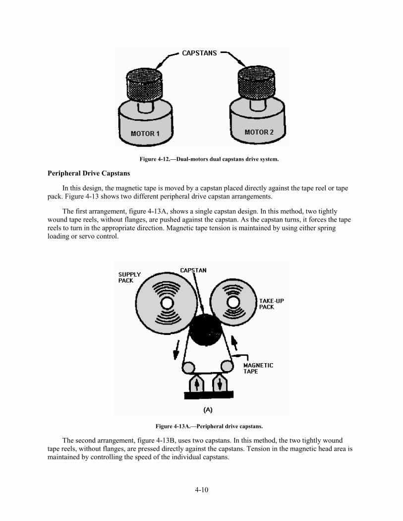
4-10
Figure 4-12.—Dual-motors dual capstans drive system.
Peripheral Drive Capstans
In this design, the magnetic tape is moved by a capstan placed directly against the tape reel or tape pack. Figure 4-13 shows two different peripheral drive capstan arrangements.
The first arrangement, figure 4-13A, shows a single capstan design. In this method, two tightly wound tape reels, without flanges, are pushed against the capstan. As the capstan turns, it forces the tape reels to turn in the appropriate direction. Magnetic tape tension is maintained by using either spring loading or servo control.
Figure 4-13A.—Peripheral drive capstans.
The second arrangement, figure 4-13B, uses two capstans. In this method, the two tightly wound tape reels, without flanges, are pressed directly against the capstans. Tension in the magnetic head area is maintained by controlling the speed of the individual capstans.
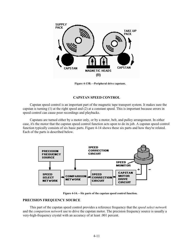
4-11
Figure 4-13B.—Peripheral drive capstans.
CAPSTAN SPEED CONTROL
Capstan speed control is an important part of the magnetic tape transport system. It makes sure the capstan is turning (1) at the right speed and (2) at a constant speed. This is important because errors in speed control can cause poor recordings and playbacks.
Capstans are turned either by a motor only, or by a motor, belt, and pulley arrangement. In either case, it's the motor that the capstan speed control function acts upon to do its job. A capstan speed control function typically consists of six basic parts. Figure 4-14 shows these six parts and how they're related. Each of the parts is described below.
Figure 4-14.—Six parts of the capstan speed control function.
PRECISION FREQUENCY SOURCE
This part of the capstan speed control provides a reference frequency that the speed select network and the comparison network use to drive the capstan motor. The precision frequency source is usually a very-high-frequency crystal with an accuracy of at least .001 percent.
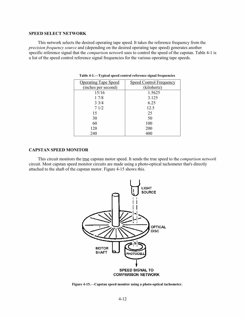
4-12
SPEED SELECT NETWORK
This network selects the desired operating tape speed. It takes the reference frequency from the precision frequency source and (depending on the desired operating tape speed) generates another specific reference signal that the comparison network uses to control the speed of the capstan. Table 4-1 is a list of the speed control reference signal frequencies for the various operating tape speeds.
Table 4-1.—Typical speed control reference signal frequencies
Operating Tape Speed (inches per second)
Speed Control Frequency (kilohertz)
15/16 1.5625 1 7/8 3.125 3 3/4 6.25 7 1/2 12.5
15 25 30 50 60 100
120 200 240 400
CAPSTAN SPEED MONITOR
This circuit monitors the true capstan motor speed. It sends the true speed to the comparison network circuit. Most capstan speed monitor circuits are made using a photo-optical tachometer that's directly attached to the shaft of the capstan motor. Figure 4-15 shows this.
Figure 4-15.—Capstan speed monitor using a photo-optical tachometer.
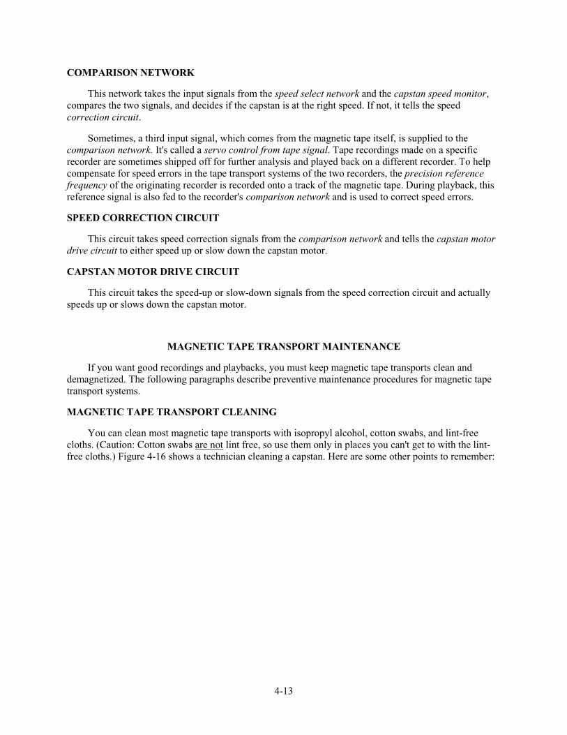
4-13
COMPARISON NETWORK
This network takes the input signals from the speed select network and the capstan speed monitor, compares the two signals, and decides if the capstan is at the right speed. If not, it tells the speed correction circuit.
Sometimes, a third input signal, which comes from the magnetic tape itself, is supplied to the comparison network. It's called a servo control from tape signal. Tape recordings made on a specific recorder are sometimes shipped off for further analysis and played back on a different recorder. To help compensate for speed errors in the tape transport systems of the two recorders, the precision reference frequency of the originating recorder is recorded onto a track of the magnetic tape. During playback, this reference signal is also fed to the recorder's comparison network and is used to correct speed errors.
SPEED CORRECTION CIRCUIT
This circuit takes speed correction signals from the comparison network and tells the capstan motor drive circuit to either speed up or slow down the capstan motor.
CAPSTAN MOTOR DRIVE CIRCUIT
This circuit takes the speed-up or slow-down signals from the speed correction circuit and actually speeds up or slows down the capstan motor.
MAGNETIC TAPE TRANSPORT MAINTENANCE
If you want good recordings and playbacks, you must keep magnetic tape transports clean and demagnetized. The following paragraphs describe preventive maintenance procedures for magnetic tape transport systems.
MAGNETIC TAPE TRANSPORT CLEANING
You can clean most magnetic tape transports with isopropyl alcohol, cotton swabs, and lint-free cloths. (Caution: Cotton swabs are not lint free, so use them only in places you can't get to with the lint-free cloths.) Figure 4-16 shows a technician cleaning a capstan. Here are some other points to remember:
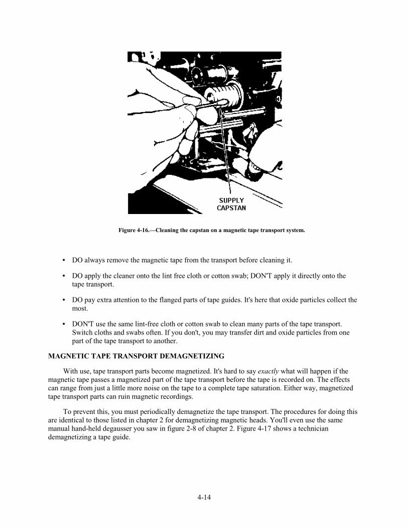
4-14
Figure 4-16.—Cleaning the capstan on a magnetic tape transport system.
• DO always remove the magnetic tape from the transport before cleaning it.
• DO apply the cleaner onto the lint free cloth or cotton swab; DON'T apply it directly onto the tape transport.
• DO pay extra attention to the flanged parts of tape guides. It's here that oxide particles collect the most.
• DON'T use the same lint-free cloth or cotton swab to clean many parts of the tape transport. Switch cloths and swabs often. If you don't, you may transfer dirt and oxide particles from one part of the tape transport to another.
MAGNETIC TAPE TRANSPORT DEMAGNETIZING
With use, tape transport parts become magnetized. It's hard to say exactly what will happen if the magnetic tape passes a magnetized part of the tape transport before the tape is recorded on. The effects can range from just a little more noise on the tape to a complete tape saturation. Either way, magnetized tape transport parts can ruin magnetic recordings.
To prevent this, you must periodically demagnetize the tape transport. The procedures for doing this are identical to those listed in chapter 2 for demagnetizing magnetic heads. You'll even use the same manual hand-held degausser you saw in figure 2-8 of chapter 2. Figure 4-17 shows a technician demagnetizing a tape guide.
4-15
Figure 4-17.—Demagnetizing a tape guide with a hand-held degausser.
Q-8. There are two types of tape transport configurations, open-loop capstan drive and closed-loop capstan drive. What are two major disadvantages of open-loop capstan drive tape transports?
Q-9. How do closed-loop capstan drive tape transports overcome the disadvantages of the open-loop drive design?
Q-10. What are the three most common closed-loop capstan drive designs?
Q-11. How do tape transports with differential velocity capstans maintain a constant tape tension in the area around the magnetic heads?
Q-12. How do dual-motor dual capstan drives maintain a constant tape tension while operating in either a forward or reverse direction?
Q-13. What are the two critical functions of the capstan speed control part of a magnetic tape transport system?
Q-14. Which part of the capstan speed control function monitors the true capstan motor speed?
Q-15. Sometimes it's necessary, but why should you avoid using cotton swabs when cleaning a magnetic tape transport?
Q-16. When cleaning the parts of a tape transport, why should you switch lint-free cloths and swabs often?
Q-17. What equipment should you use to de-magnetize a magnetic tape transport?
4-16
SUMMARY
Now that you've finished chapter 4, you should be able to describe magnetic tape transport systems in terms of their operating characteristics, parts, and preventive maintenance requirements. The following is a summary of the important points in this chapter.
A MAGNETIC TAPE RECORDER TRANSPORT has four basic parts: (1) tape reeling system, (2) tape speed control system, (3) electronic subsystem, and (4) basic enclosure.
The TAPE REELING SYSTEM must move the tape in a straight line at a constant tension, and it must start and stop smoothly while maintaining the proper tension.
Three of the MOST COMMON REELING SYSTEMS are (1) take-up control, (2) two-motor reeling, and (3) tape buffering.
The two types of TAPE TRANSPORT CONFIGURATIONS are (1) open-loop capstan drive and (2) closed-loop capstan drive. The open-loop type works in only one direction, and the tape tension can vary. The closed-loop type keeps the tape tension constant.
Three types of CLOSED-LOOP CAPSTAN DRIVES are (1) differential velocity capstans, (2) dual-motors dual capstans, and (3) peripheral drive capstans.
The CAPSTAN SPEED CONTROL component of a tape transport keeps the capstan turning at the correct operating speed and at a constant speed. It has these six parts: (1) precision frequency source, (2) speed select network, (3) capstan speed motor, (4) comparison network, (5) speed correction circuit, and (6) capstan motor drive circuit.
You should CLEAN magnetic tape transports with isopropyl alcohol, cotton swabs, and lint free cloths and DEMAGNETIZE them using a hand-held degausser.
ANSWERS TO QUESTIONS Q1. THROUGH Q17.
A1.
a. Tape reeling system.
b. Tape speed control system.
c. Electronic subsystem.
d. Basic enclosure.
A2.
a. Take-up control.
b. Two-motor reeling.
c. Tape buffering.
4-17
A3.
a. It only works in one direction.
b. The tape tension varies as the supply reel unwinds, which can cause damage during starts and stops.
A4. The two-motor configuration runs in both directions and a holdback voltage helps control tape tension, but it does not properly control tape tension during starts and stops.
A5. A tape buffering reeling system.
A6.
a. Spring-tension buffering systems.
b. Vacuum-column buffering systems.
A7. They keep the tape straight with respect to both the supply and take-up reels and the magnetic heads.
A8.
a. Only operates in one direction.
b. The tape tension and head-to-tape contact can vary.
A9. Closed loop capstan drive transports use more than one capstan to clamp the tape in the area around the magnetic head.
A10.
a. Differential velocity capstans.
b. Dual motors dual capstans.
c. Peripheral drive capstans.
A11. The supply capstan is slightly larger than the take-up capstan. This causes the take-up capstan to pull the tape slightly faster than the supply capstan feeds the tape.
A12. Each capstan is driven by its own motor. It maintains tape tension by slowing down one of the motors. When the tape motion is reversed, the opposite motor is slowed down.
A13. Makes sure the capstan turns at the right speed and at a constant speed.
A14. Capstan speed monitor.
A15. Cotton swabs are not lint free.
A16. You may transfer dirt or oxide particles from one part of the tape transport to another.
A17. A hand-held degausser.

5-1
CHAPTER 5
MAGNETIC TAPE RECORDER RECORD ANDREPRODUCE ELECTRONICS
LEARNING OBJECTIVES
After completing this chapter, you’ll be able to do the following:
1. State the two types of record and reproduce electronics used on magnetic tape recorders.
2. Describe the purpose and function of direct record electronics and the four main parts of arecorder’s direct record component.
3. Describe the purpose and function of direct reproduce electronics and the three main parts of arecorder’s direct reproduce component.
4. Describe the purpose and function of frequency modulation (FM) record electronics and the threemain parts of a recorder’s FM record component.
5. Describe the purpose and function of FM reproduce electronics and the four main parts of arecorder’s FM record component.
RECORD AND REPRODUCE ELECTRONICS
There are two ways to record and reproduce analog signals. The first way is direct record. It’s alsocalled amplitude modulation (AM) electronics. The second way is frequency modulation (FM). Eventhough direct record and reproduce circuits are much different from FM record and reproduce electronics,they both share the same two very important jobs. They both must:
1. Take an input signal, process it as needed, and then send it to the record magnetic head forreproduction.
2. Take the reproduced signal from the reproduce magnetic head, process it as needed, and output itfor listening or analysis.
DIRECT RECORD ELECTRONICS
Direct record electronics record input signals onto magnetic media just as the signals appeared at therecorder’s input. The only processing an input signal receives is the adding of a bias signal. The addedbias signal makes sure the signal stays away from the steps of the magnetism curve. Figure 5-1 shows abasic block diagram of a recorder’s direct record electronics.
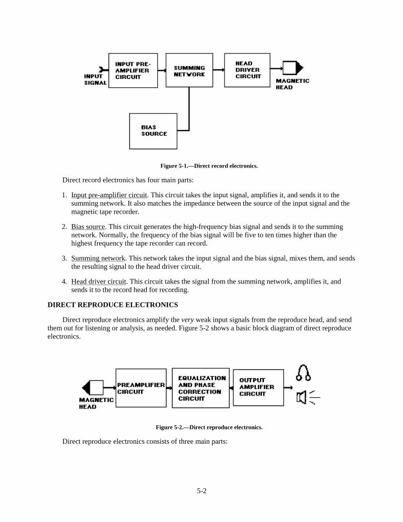
5-2
Figure 5-1.—Direct record electronics.
Direct record electronics has four main parts:
1. Input pre-amplifier circuit. This circuit takes the input signal, amplifies it, and sends it to thesumming network. It also matches the impedance between the source of the input signal and themagnetic tape recorder.
2. Bias source. This circuit generates the high-frequency bias signal and sends it to the summingnetwork. Normally, the frequency of the bias signal will be five to ten times higher than thehighest frequency the tape recorder can record.
3. Summing network. This network takes the input signal and the bias signal, mixes them, and sendsthe resulting signal to the head driver circuit.
4. Head driver circuit. This circuit takes the signal from the summing network, amplifies it, andsends it to the record head for recording.
DIRECT REPRODUCE ELECTRONICS
Direct reproduce electronics amplify the very weak input signals from the reproduce head, and sendthem out for listening or analysis, as needed. Figure 5-2 shows a basic block diagram of direct reproduceelectronics.
Figure 5-2.—Direct reproduce electronics.
Direct reproduce electronics consists of three main parts:
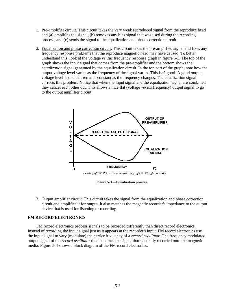
5-3
1. Pre-amplifier circuit. This circuit takes the very weak reproduced signal from the reproduce headand (a) amplifies the signal, (b) removes any bias signal that was used during the recordingprocess, and (c) sends the signal to the equalization and phase correction circuit.
2. Equalization and phase correction circuit. This circuit takes the pre-amplified signal and fixes anyfrequency response problems that the reproduce magnetic head may have caused. To betterunderstand this, look at the voltage versus frequency response graph in figure 5-3. The top of thegraph shows the input signal that comes from the pre-amplifier and the bottom shows theequalization signal generated by the equalization circuit. In the top part of the graph, note how theoutput voltage level varies as the frequency of the signal varies. This isn’t good. A good outputvoltage level is one that remains constant as the frequency changes. The equalization signalcorrects this problem. Notice that when the input signal and the equalization signal are combinedthey cancel each other out. This allows a nice flat (voltage versus frequency) output signal to goto the output amplifier circuit.
Figure 5-3.—Equalization process.
3. Output amplifier circuit. This circuit takes the signal from the equalization and phase correctioncircuit and amplifies it for output. It also matches the magnetic recorder’s impedance to the outputdevice that is used for listening or recording.
FM RECORD ELECTRONICS
FM record electronics process signals to be recorded differently than direct record electronics.Instead of recording the input signal just as it appears at the recorder’s input, FM record electronics usethe input signal to vary (modulate) the carrier frequency of a record oscillator. The frequency modulatedoutput signal of the record oscillator then becomes the signal that’s actually recorded onto the magneticmedia. Figure 5-4 shows a block diagram of the FM record electronics.
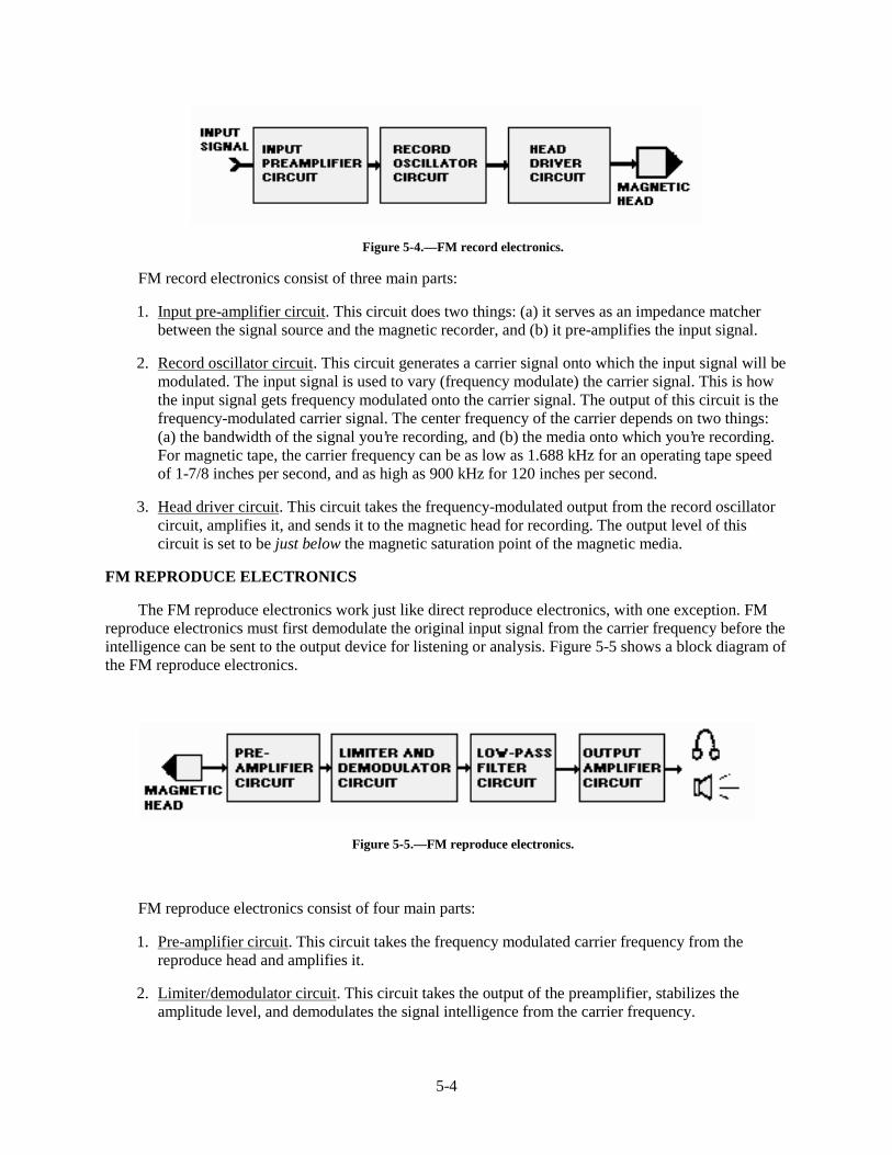
5-4
Figure 5-4.—FM record electronics.
FM record electronics consist of three main parts:
1. Input pre-amplifier circuit. This circuit does two things: (a) it serves as an impedance matcherbetween the signal source and the magnetic recorder, and (b) it pre-amplifies the input signal.
2. Record oscillator circuit. This circuit generates a carrier signal onto which the input signal will bemodulated. The input signal is used to vary (frequency modulate) the carrier signal. This is howthe input signal gets frequency modulated onto the carrier signal. The output of this circuit is thefrequency-modulated carrier signal. The center frequency of the carrier depends on two things:(a) the bandwidth of the signal you’re recording, and (b) the media onto which you’re recording.For magnetic tape, the carrier frequency can be as low as 1.688 kHz for an operating tape speedof 1-7/8 inches per second, and as high as 900 kHz for 120 inches per second.
3. Head driver circuit. This circuit takes the frequency-modulated output from the record oscillatorcircuit, amplifies it, and sends it to the magnetic head for recording. The output level of thiscircuit is set to be just below the magnetic saturation point of the magnetic media.
FM REPRODUCE ELECTRONICS
The FM reproduce electronics work just like direct reproduce electronics, with one exception. FMreproduce electronics must first demodulate the original input signal from the carrier frequency before theintelligence can be sent to the output device for listening or analysis. Figure 5-5 shows a block diagram ofthe FM reproduce electronics.
Figure 5-5.—FM reproduce electronics.
FM reproduce electronics consist of four main parts:
1. Pre-amplifier circuit. This circuit takes the frequency modulated carrier frequency from thereproduce head and amplifies it.
2. Limiter/demodulator circuit. This circuit takes the output of the preamplifier, stabilizes theamplitude level, and demodulates the signal intelligence from the carrier frequency.
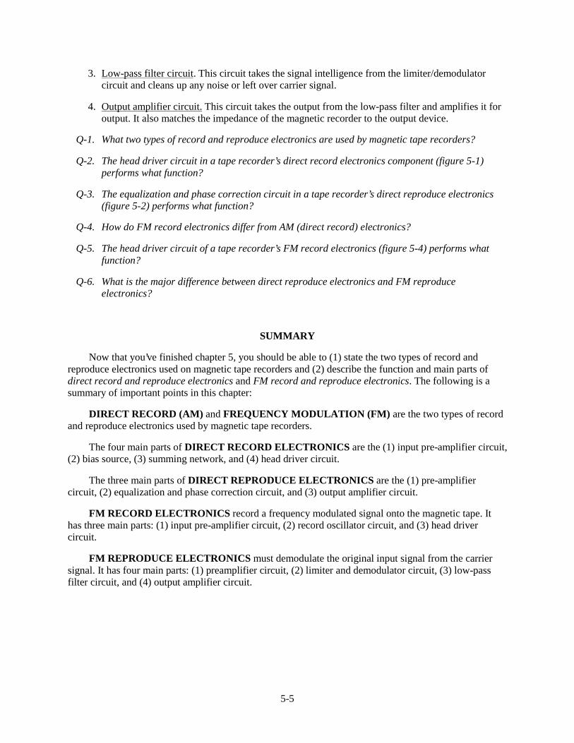
5-5
3. Low-pass filter circuit. This circuit takes the signal intelligence from the limiter/demodulatorcircuit and cleans up any noise or left over carrier signal.
4. Output amplifier circuit. This circuit takes the output from the low-pass filter and amplifies it foroutput. It also matches the impedance of the magnetic recorder to the output device.
Q-1. What two types of record and reproduce electronics are used by magnetic tape recorders?
Q-2. The head driver circuit in a tape recorder’s direct record electronics component (figure 5-1)performs what function?
Q-3. The equalization and phase correction circuit in a tape recorder’s direct reproduce electronics(figure 5-2) performs what function?
Q-4. How do FM record electronics differ from AM (direct record) electronics?
Q-5. The head driver circuit of a tape recorder’s FM record electronics (figure 5-4) performs whatfunction?
Q-6. What is the major difference between direct reproduce electronics and FM reproduceelectronics?
SUMMARY
Now that you’ve finished chapter 5, you should be able to (1) state the two types of record andreproduce electronics used on magnetic tape recorders and (2) describe the function and main parts ofdirect record and reproduce electronics and FM record and reproduce electronics. The following is asummary of important points in this chapter:
DIRECT RECORD (AM) and FREQUENCY MODULATION (FM) are the two types of recordand reproduce electronics used by magnetic tape recorders.
The four main parts of DIRECT RECORD ELECTRONICS are the (1) input pre-amplifier circuit,(2) bias source, (3) summing network, and (4) head driver circuit.
The three main parts of DIRECT REPRODUCE ELECTRONICS are the (1) pre-amplifiercircuit, (2) equalization and phase correction circuit, and (3) output amplifier circuit.
FM RECORD ELECTRONICS record a frequency modulated signal onto the magnetic tape. Ithas three main parts: (1) input pre-amplifier circuit, (2) record oscillator circuit, and (3) head drivercircuit.
FM REPRODUCE ELECTRONICS must demodulate the original input signal from the carriersignal. It has four main parts: (1) preamplifier circuit, (2) limiter and demodulator circuit, (3) low-passfilter circuit, and (4) output amplifier circuit.
5-6
ANSWERS TO QUESTIONS Q1. THROUGH Q6.
A1.
a. Direct record (AM).
b. Frequency modulation (FM).
A2. It takes the signal from the summing network, amplifies it, and sends it to the record head forrecording.
A3. It generates an equalization signal which corrects any frequency response problems in the inputsignal from the pre-amplifier circuit.
A4. Instead of recording the signal just as it appears at the recorder’s input, FM record electronicsrecords a frequency-modulated carrier signal from a record oscillator (figure 5-4) onto themagnetic tape.
A5. It amplifies the frequency-modulated output from the record oscillator and sends it to the recordhead.
A6. FM record electronics must use a limiter and demodulator circuit (figure 5-5) to demodulate thesignal intelligence from the carrier frequency.
6-1
CHAPTER 6
MAGNETIC TAPE RECORDING SPECIFICATIONS
LEARNING OBJECTIVES
After completing this chapter, you’ll be able to do the following:
1. Define the seven most common magnetic tape recording specifications.
2. Describe a magnetic tape recorder’s signal-to-noise ratio (SNR) specification, how it’s measured,and why a high SNR is important.
3. Describe a tape recorder/reproducer’s frequency-response specification, how it’s measured, andthe three factors that can limit or degrade a recorder’s frequency response.
4. Describe a tape recorder’s harmonic-distortion specification, how it’s measured, and how arecorder produces harmonic distortion.
5. Describe a recorder’s phase-response specification, how it’s measured, and why good phaseresponse is important.
6. Describe a recorder’s flutter specification, how it’s measured, and why minimal flutter isimportant.
7. Describe a recorder’s time-base error (TBE) specification, how it’s measured, and why minimalTBE is important.
8. Describe a multi-track magnetic tape recorder’s skew specification, how it’s measured, and whyminimal skew is important.
INTRODUCTION
Have you ever gone to a store to buy a magnetic tape recorder? Were you able to decide which of thedisplayed models was the good one to buy? Or, did you instead end up confused when the salespersonstarted spouting words like SNR, flutter, and bandwidth. If so, you weren’t alone.
This chapter (1) defines the seven most common magnetic tape recording specifications,(2) describes their effect on the magnetic recording process, and (3) tells how to measure eachspecification. The remaining paragraphs in this chapter describe each of the following magnetic taperecorder specifications:
1. Signal-to-noise ratio
2. Frequency response
3. Harmonic distortion
4. Phase response
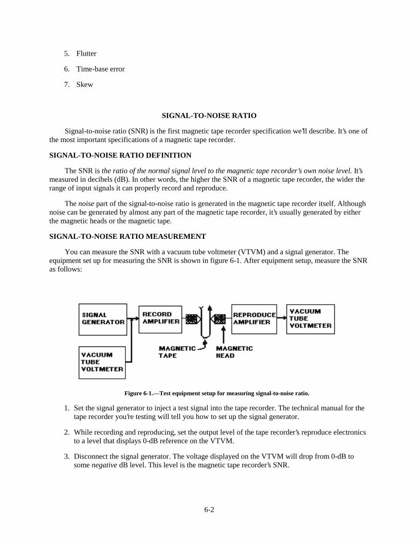
6-2
5. Flutter
6. Time-base error
7. Skew
SIGNAL-TO-NOISE RATIO
Signal-to-noise ratio (SNR) is the first magnetic tape recorder specification we’ll describe. It’s one ofthe most important specifications of a magnetic tape recorder.
SIGNAL-TO-NOISE RATIO DEFINITION
The SNR is the ratio of the normal signal level to the magnetic tape recorder’s own noise level. It’smeasured in decibels (dB). In other words, the higher the SNR of a magnetic tape recorder, the wider therange of input signals it can properly record and reproduce.
The noise part of the signal-to-noise ratio is generated in the magnetic tape recorder itself. Althoughnoise can be generated by almost any part of the magnetic tape recorder, it’s usually generated by eitherthe magnetic heads or the magnetic tape.
SIGNAL-TO-NOISE RATIO MEASUREMENT
You can measure the SNR with a vacuum tube voltmeter (VTVM) and a signal generator. Theequipment set up for measuring the SNR is shown in figure 6-1. After equipment setup, measure the SNRas follows:
Figure 6-1.—Test equipment setup for measuring signal-to-noise ratio.
1. Set the signal generator to inject a test signal into the tape recorder. The technical manual for thetape recorder you’re testing will tell you how to set up the signal generator.
2. While recording and reproducing, set the output level of the tape recorder’s reproduce electronicsto a level that displays 0-dB reference on the VTVM.
3. Disconnect the signal generator. The voltage displayed on the VTVM will drop from 0-dB tosome negative dB level. This level is the magnetic tape recorder’s SNR.
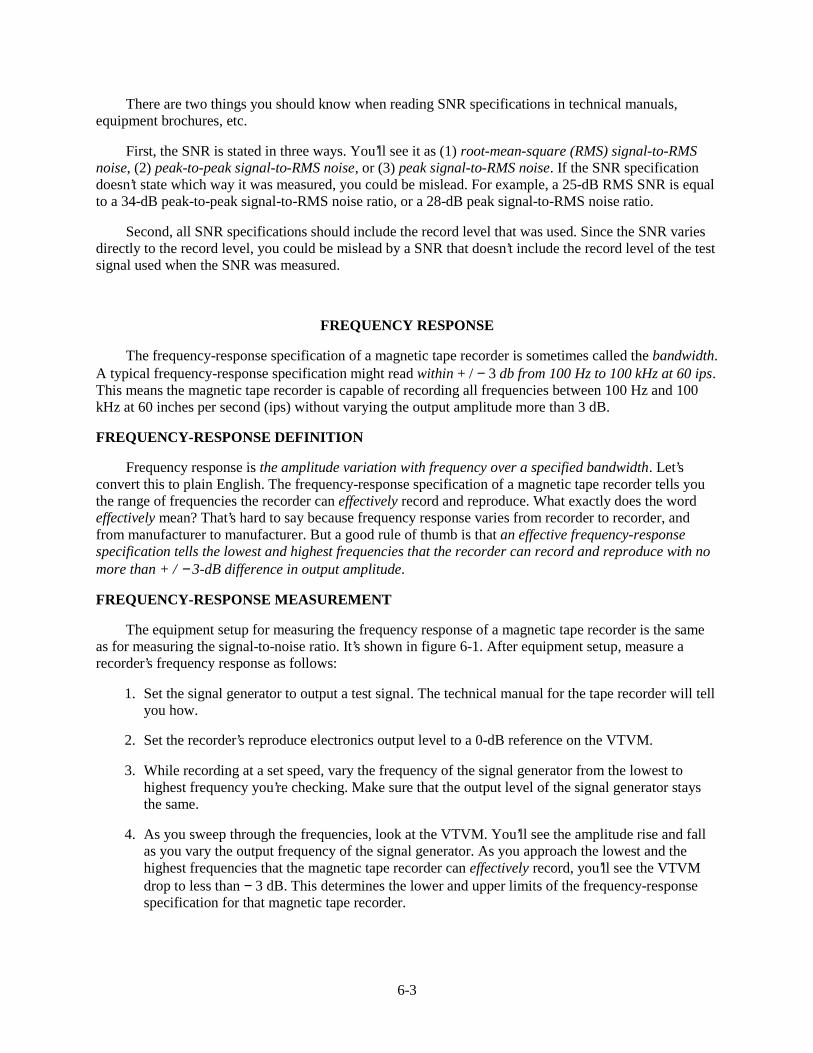
6-3
There are two things you should know when reading SNR specifications in technical manuals,equipment brochures, etc.
First, the SNR is stated in three ways. You’ll see it as (1) root-mean-square (RMS) signal-to-RMSnoise, (2) peak-to-peak signal-to-RMS noise, or (3) peak signal-to-RMS noise. If the SNR specificationdoesn’t state which way it was measured, you could be mislead. For example, a 25-dB RMS SNR is equalto a 34-dB peak-to-peak signal-to-RMS noise ratio, or a 28-dB peak signal-to-RMS noise ratio.
Second, all SNR specifications should include the record level that was used. Since the SNR variesdirectly to the record level, you could be mislead by a SNR that doesn’t include the record level of the testsignal used when the SNR was measured.
FREQUENCY RESPONSE
The frequency-response specification of a magnetic tape recorder is sometimes called the bandwidth.A typical frequency-response specification might read within + / − 3 db from 100 Hz to 100 kHz at 60 ips.This means the magnetic tape recorder is capable of recording all frequencies between 100 Hz and 100kHz at 60 inches per second (ips) without varying the output amplitude more than 3 dB.
FREQUENCY-RESPONSE DEFINITION
Frequency response is the amplitude variation with frequency over a specified bandwidth. Let’sconvert this to plain English. The frequency-response specification of a magnetic tape recorder tells youthe range of frequencies the recorder can effectively record and reproduce. What exactly does the wordeffectively mean? That’s hard to say because frequency response varies from recorder to recorder, andfrom manufacturer to manufacturer. But a good rule of thumb is that an effective frequency-responsespecification tells the lowest and highest frequencies that the recorder can record and reproduce with nomore than + / − 3-dB difference in output amplitude.
FREQUENCY-RESPONSE MEASUREMENT
The equipment setup for measuring the frequency response of a magnetic tape recorder is the sameas for measuring the signal-to-noise ratio. It’s shown in figure 6-1. After equipment setup, measure arecorder’s frequency response as follows:
1. Set the signal generator to output a test signal. The technical manual for the tape recorder will tellyou how.
2. Set the recorder’s reproduce electronics output level to a 0-dB reference on the VTVM.
3. While recording at a set speed, vary the frequency of the signal generator from the lowest tohighest frequency you’re checking. Make sure that the output level of the signal generator staysthe same.
4. As you sweep through the frequencies, look at the VTVM. You’ll see the amplitude rise and fallas you vary the output frequency of the signal generator. As you approach the lowest and thehighest frequencies that the magnetic tape recorder can effectively record, you’ll see the VTVMdrop to less than − 3 dB. This determines the lower and upper limits of the frequency-responsespecification for that magnetic tape recorder.
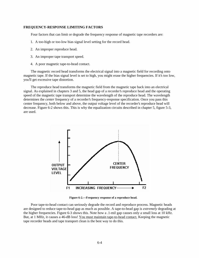
6-4
FREQUENCY-RESPONSE LIMITING FACTORS
Four factors that can limit or degrade the frequency response of magnetic tape recorders are:
1. A too-high or too-low bias signal level setting for the record head.
2. An improper reproduce head.
3. An improper tape transport speed.
4. A poor magnetic tape-to-head contact.
The magnetic record head transforms the electrical signal into a magnetic field for recording ontomagnetic tape. If the bias signal level is set to high, you might erase the higher frequencies. If it’s too low,you’ll get excessive tape distortion.
The reproduce head transforms the magnetic field from the magnetic tape back into an electricalsignal. As explained in chapters 3 and 5, the head gap of a recorder’s reproduce head and the operatingspeed of the magnetic tape transport determine the wavelength of the reproduce head. The wavelengthdetermines the center frequency of a recorder’s frequency-response specification. Once you pass thiscenter frequency, both below and above, the output voltage level of the recorder’s reproduce head willdecrease. Figure 6-2 shows this. This is why the equalization circuits described in chapter 5, figure 5-3,are used.
Figure 6-2.—Frequency response of a reproduce head.
Poor tape-to-head contact can seriously degrade the record and reproduce process. Magnetic headsare designed to reduce tape-to-head gap as much as possible. A tape-to-head gap is extremely degrading atthe higher frequencies. Figure 6-3 shows this. Note how a .1-mil gap causes only a small loss at 10 kHz.But, at 1 MHz, it causes a 46-dB loss! You must maintain tape-to-head contact. Keeping the magnetictape recorder heads and tape transport clean is the best way to do this.
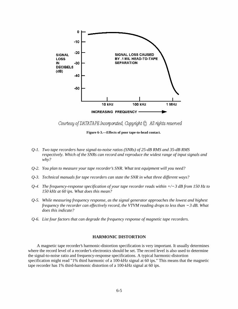
6-5
Figure 6-3.—Effects of poor tape-to-head contact.
Q-1. Two tape recorders have signal-to-noise ratios (SNRs) of 25-dB RMS and 35-dB RMSrespectively. Which of the SNRs can record and reproduce the widest range of input signals andwhy?
Q-2. You plan to measure your tape recorder’s SNR. What test equipment will you need?
Q-3. Technical manuals for tape recorders can state the SNR in what three different ways?
Q-4. The frequency-response specification of your tape recorder reads within +/− 3 dB from 150 Hz to150 kHz at 60 ips. What does this mean?
Q-5. While measuring frequency response, as the signal generator approaches the lowest and highestfrequency the recorder can effectively record, the VTVM reading drops to less than − 3 dB. Whatdoes this indicate?
Q-6. List four factors that can degrade the frequency response of magnetic tape recorders.
HARMONIC DISTORTION
A magnetic tape recorder’s harmonic-distortion specification is very important. It usually determineswhere the record level of a recorder’s electronics should be set. The record level is also used to determinethe signal-to-noise ratio and frequency-response specifications. A typical harmonic-distortionspecification might read "1% third harmonic of a 100-kHz signal at 60 ips." This means that the magnetictape recorder has 1% third-harmonic distortion of a 100-kHz signal at 60 ips.
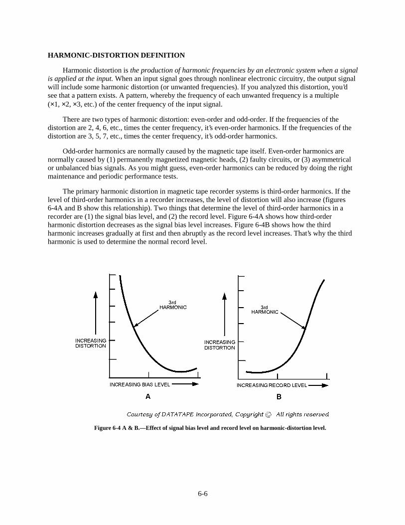
6-6
HARMONIC-DISTORTION DEFINITION
Harmonic distortion is the production of harmonic frequencies by an electronic system when a signalis applied at the input. When an input signal goes through nonlinear electronic circuitry, the output signalwill include some harmonic distortion (or unwanted frequencies). If you analyzed this distortion, you’dsee that a pattern exists. A pattern, whereby the frequency of each unwanted frequency is a multiple(×1, ×2, ×3, etc.) of the center frequency of the input signal.
There are two types of harmonic distortion: even-order and odd-order. If the frequencies of thedistortion are 2, 4, 6, etc., times the center frequency, it’s even-order harmonics. If the frequencies of thedistortion are 3, 5, 7, etc., times the center frequency, it’s odd-order harmonics.
Odd-order harmonics are normally caused by the magnetic tape itself. Even-order harmonics arenormally caused by (1) permanently magnetized magnetic heads, (2) faulty circuits, or (3) asymmetricalor unbalanced bias signals. As you might guess, even-order harmonics can be reduced by doing the rightmaintenance and periodic performance tests.
The primary harmonic distortion in magnetic tape recorder systems is third-order harmonics. If thelevel of third-order harmonics in a recorder increases, the level of distortion will also increase (figures6-4A and B show this relationship). Two things that determine the level of third-order harmonics in arecorder are (1) the signal bias level, and (2) the record level. Figure 6-4A shows how third-orderharmonic distortion decreases as the signal bias level increases. Figure 6-4B shows how the thirdharmonic increases gradually at first and then abruptly as the record level increases. That’s why the thirdharmonic is used to determine the normal record level.
Figure 6-4 A & B.—Effect of signal bias level and record level on harmonic-distortion level.
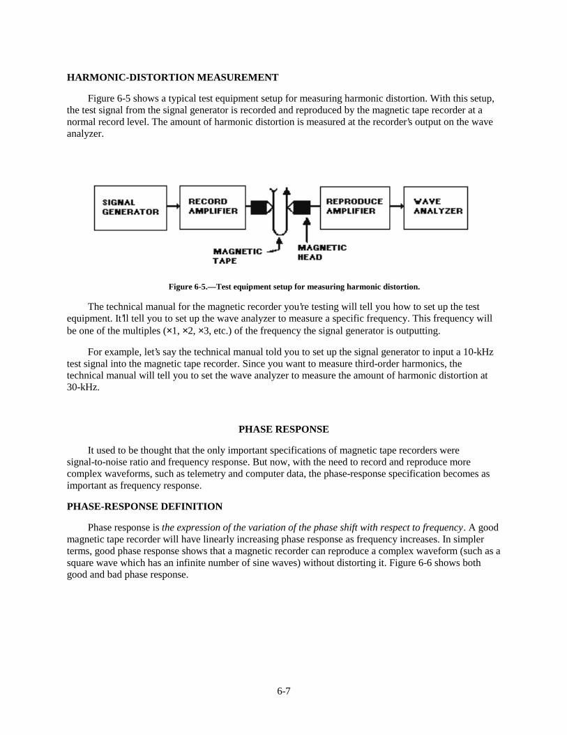
6-7
HARMONIC-DISTORTION MEASUREMENT
Figure 6-5 shows a typical test equipment setup for measuring harmonic distortion. With this setup,the test signal from the signal generator is recorded and reproduced by the magnetic tape recorder at anormal record level. The amount of harmonic distortion is measured at the recorder’s output on the waveanalyzer.
Figure 6-5.—Test equipment setup for measuring harmonic distortion.
The technical manual for the magnetic recorder you’re testing will tell you how to set up the testequipment. It’ll tell you to set up the wave analyzer to measure a specific frequency. This frequency willbe one of the multiples (×1, ×2, ×3, etc.) of the frequency the signal generator is outputting.
For example, let’s say the technical manual told you to set up the signal generator to input a 10-kHztest signal into the magnetic tape recorder. Since you want to measure third-order harmonics, thetechnical manual will tell you to set the wave analyzer to measure the amount of harmonic distortion at30-kHz.
PHASE RESPONSE
It used to be thought that the only important specifications of magnetic tape recorders weresignal-to-noise ratio and frequency response. But now, with the need to record and reproduce morecomplex waveforms, such as telemetry and computer data, the phase-response specification becomes asimportant as frequency response.
PHASE-RESPONSE DEFINITION
Phase response is the expression of the variation of the phase shift with respect to frequency. A goodmagnetic tape recorder will have linearly increasing phase response as frequency increases. In simplerterms, good phase response shows that a magnetic recorder can reproduce a complex waveform (such as asquare wave which has an infinite number of sine waves) without distorting it. Figure 6-6 shows bothgood and bad phase response.
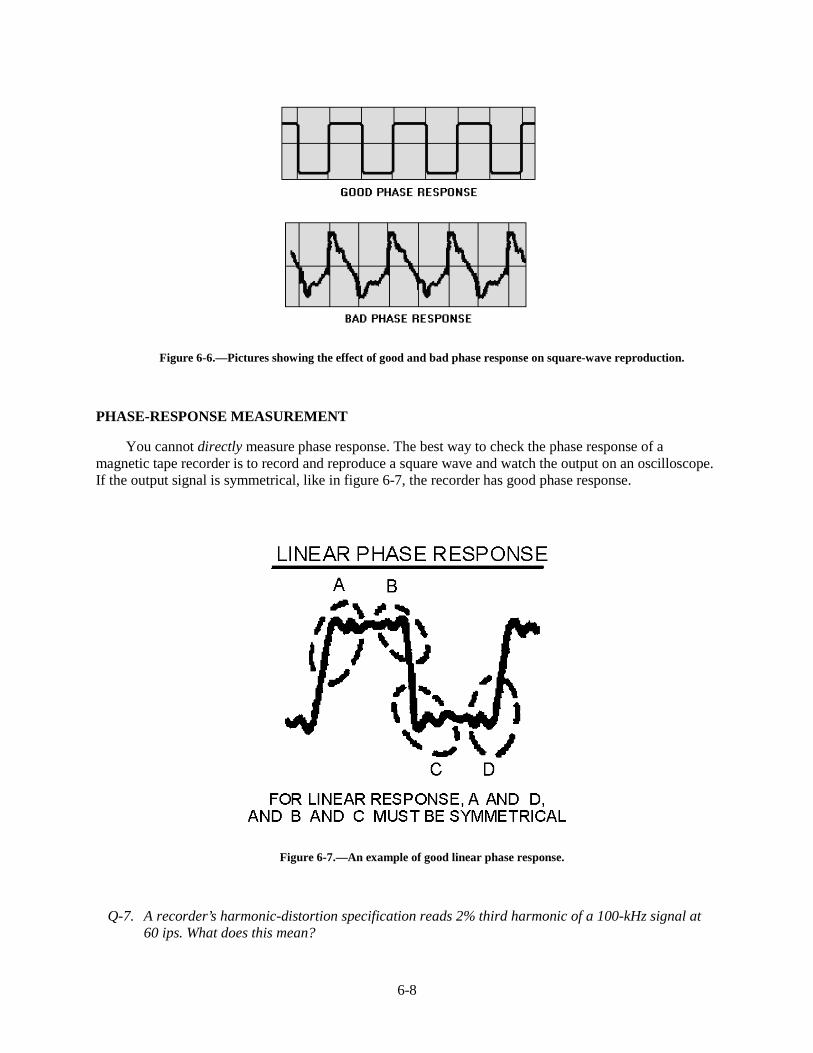
6-8
Figure 6-6.—Pictures showing the effect of good and bad phase response on square-wave reproduction.
PHASE-RESPONSE MEASUREMENT
You cannot directly measure phase response. The best way to check the phase response of amagnetic tape recorder is to record and reproduce a square wave and watch the output on an oscilloscope.If the output signal is symmetrical, like in figure 6-7, the recorder has good phase response.
Figure 6-7.—An example of good linear phase response.
Q-7. A recorder’s harmonic-distortion specification reads 2% third harmonic of a 100-kHz signal at60 ips. What does this mean?
6-9
Q-8. What are three possible causes of even-order harmonics?
Q-9. What number harmonic is the primary harmonic distortion in magnetic tape recorders?
Q-10. When measuring harmonic distortion, you set the signal generator to input a 15-kHz test signal.To what frequency should you set the wave analyzer?
Q-11. How should a tape recorder with good phase response reproduce a complex waveform, such as asquare wave?
Q-12. How could you check the phase response of a tape recorder?
FLUTTER
The general audio and broadcast field coined the term flutter to describe what you’ll actually hearfrom the bad effects of this specification.
FLUTTER DEFINITION
Flutter is the result of non-uniform tape motion caused by variations in tape speed that producesfrequency modulation of signals recorded onto magnetic tape.
Flutter is usually expressed as a percent peak or a peak-to-peak value for instrumentation recordersand as a root-mean-square (RMS) value for audio recorders. It’s caused by magnetic tape transports.Low-frequency flutter (below 1000 Hz) is caused by the rotating parts of a tape transport such as:
• Irregular magnetic tape supply or take-up reels.
• Uneven or sticking guide rollers and pinch rollers.
• Capstans.
High-frequency flutter (above 1000 Hz) is caused by the fixed parts of a tape transport, such as fixedtape guides and magnetic heads. When the magnetic tape passes over a fixed tape guide or magnetic head,the transition from static to dynamic friction causes something called stiction. It’s this stiction that causesthe variations in tape speed which, in turn, cause the flutter.
As you might guess, it’s hard to prevent flutter. The only way to lessen flutter is through skilledengineering, machining, and design of magnetic tape recorders.
FLUTTER MEASUREMENT
There are many ways to measure flutter. Most are based on the fact that tape speed variations causefrequency modulation of a recorded tone. Figure 6-8 shows a typical setup for measuring the peak-to-peakvalue of flutter with a frequency-modulation (FM) demodulator and an oscilloscope. The technicalmanual for the magnetic tape recorder you’re testing will tell you how to set up the signal generator tooutput the test signal. After setting up the test equipment, follow these procedures:
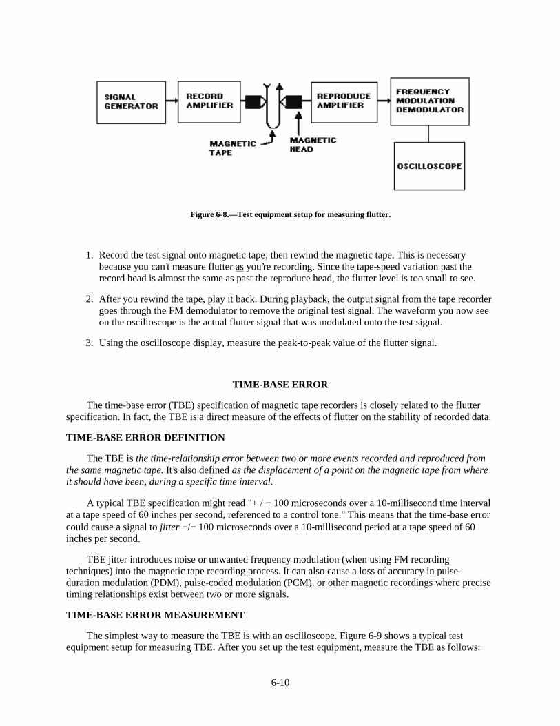
6-10
Figure 6-8.—Test equipment setup for measuring flutter.
1. Record the test signal onto magnetic tape; then rewind the magnetic tape. This is necessarybecause you can’t measure flutter as you’re recording. Since the tape-speed variation past therecord head is almost the same as past the reproduce head, the flutter level is too small to see.
2. After you rewind the tape, play it back. During playback, the output signal from the tape recordergoes through the FM demodulator to remove the original test signal. The waveform you now seeon the oscilloscope is the actual flutter signal that was modulated onto the test signal.
3. Using the oscilloscope display, measure the peak-to-peak value of the flutter signal.
TIME-BASE ERROR
The time-base error (TBE) specification of magnetic tape recorders is closely related to the flutterspecification. In fact, the TBE is a direct measure of the effects of flutter on the stability of recorded data.
TIME-BASE ERROR DEFINITION
The TBE is the time-relationship error between two or more events recorded and reproduced fromthe same magnetic tape. It’s also defined as the displacement of a point on the magnetic tape from whereit should have been, during a specific time interval.
A typical TBE specification might read "+ / − 100 microseconds over a 10-millisecond time intervalat a tape speed of 60 inches per second, referenced to a control tone." This means that the time-base errorcould cause a signal to jitter +/− 100 microseconds over a 10-millisecond period at a tape speed of 60inches per second.
TBE jitter introduces noise or unwanted frequency modulation (when using FM recordingtechniques) into the magnetic tape recording process. It can also cause a loss of accuracy in pulse-duration modulation (PDM), pulse-coded modulation (PCM), or other magnetic recordings where precisetiming relationships exist between two or more signals.
TIME-BASE ERROR MEASUREMENT
The simplest way to measure the TBE is with an oscilloscope. Figure 6-9 shows a typical testequipment setup for measuring TBE. After you set up the test equipment, measure the TBE as follows:
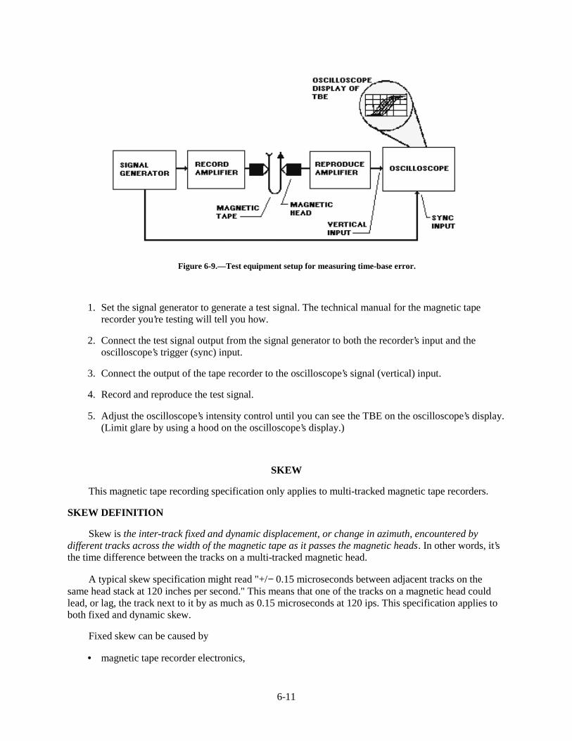
6-11
Figure 6-9.—Test equipment setup for measuring time-base error.
1. Set the signal generator to generate a test signal. The technical manual for the magnetic taperecorder you’re testing will tell you how.
2. Connect the test signal output from the signal generator to both the recorder’s input and theoscilloscope’s trigger (sync) input.
3. Connect the output of the tape recorder to the oscilloscope’s signal (vertical) input.
4. Record and reproduce the test signal.
5. Adjust the oscilloscope’s intensity control until you can see the TBE on the oscilloscope’s display.(Limit glare by using a hood on the oscilloscope’s display.)
SKEW
This magnetic tape recording specification only applies to multi-tracked magnetic tape recorders.
SKEW DEFINITION
Skew is the inter-track fixed and dynamic displacement, or change in azimuth, encountered bydifferent tracks across the width of the magnetic tape as it passes the magnetic heads. In other words, it’sthe time difference between the tracks on a multi-tracked magnetic head.
A typical skew specification might read "+/− 0.15 microseconds between adjacent tracks on thesame head stack at 120 inches per second." This means that one of the tracks on a magnetic head couldlead, or lag, the track next to it by as much as 0.15 microseconds at 120 ips. This specification applies toboth fixed and dynamic skew.
Fixed skew can be caused by
• magnetic tape recorder electronics,
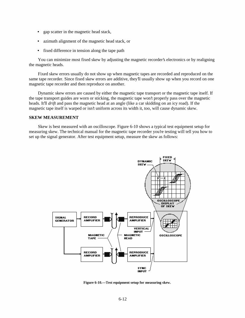
6-12
• gap scatter in the magnetic head stack,
• azimuth alignment of the magnetic head stack, or
• fixed difference in tension along the tape path
You can minimize most fixed skew by adjusting the magnetic recorder’s electronics or by realigningthe magnetic heads.
Fixed skew errors usually do not show up when magnetic tapes are recorded and reproduced on thesame tape recorder. Since fixed skew errors are additive, they’ll usually show up when you record on onemagnetic tape recorder and then reproduce on another.
Dynamic skew errors are caused by either the magnetic tape transport or the magnetic tape itself. Ifthe tape transport guides are worn or sticking, the magnetic tape won’t properly pass over the magneticheads. It’ll drift and pass the magnetic head at an angle (like a car skidding on an icy road). If themagnetic tape itself is warped or isn’t uniform across its width it, too, will cause dynamic skew.
SKEW MEASUREMENT
Skew is best measured with an oscilloscope. Figure 6-10 shows a typical test equipment setup formeasuring skew. The technical manual for the magnetic tape recorder you’re testing will tell you how toset up the signal generator. After test equipment setup, measure the skew as follows:
Figure 6-10.—Test equipment setup for measuring skew.
6-13
1. Inject the test signal into a reference track and one other track of the multi-track magnetic taperecorder. (The reference track should be one of the two outside tracks of the magnetic head.)
2. Connect the output from the reference track to the sync input of the oscilloscope to trigger thehorizontal sweep.
3. Connect the output from the other track to the vertical input of the oscilloscope.
4. While recording and reproducing the test signal, measure the fixed and dynamic skews which aredisplayed on the oscilloscope. Figure 6-10 shows how this looks.
Q-13. What causes flutter in a tape recorder’s output?
Q-14. What causes low-frequency flutter (below 1000 Hz)?
Q-15. What causes high-frequency flutter (above 1000 Hz)?
Q-16. Your recorder’s TBE specification reads " +/− 80 microseconds over a 10 millisecond timeinterval at a tape speed of 60 ips, referenced to a control tone." What does this mean?
Q-17. Why is it important to minimize TBE jitter in magnetic tape recordings where precise timingrelationships exist between two or more signals?
Q-18. The skew specification of your multi-tracked tape recorder reads " +/− 0.20 microsecondsbetween adjacent tracks on the same head stack at 120 ips." What does this mean?
Q-19. How can you minimize fixed skew?
Q-20. When are fixed skew errors most likely to show up?
Q-21. How do worn or sticking tape transport guides cause dynamic skew on a multi-track recorder?
SUMMARY
Now that you’ve finished chapter 6, you should be able to describe the seven most common magnetictape recording specifications and how to measure each specification. The following is a summary ofimportant points in this chapter:
The SIGNAL-TO-NOISE RATIO (SNR) is the ratio of the normal signal level to the taperecorder’s own noise level measured in dB. The higher a recorder’s SNR, the wider the range of signals itcan record and reproduce.
SNR IS STATED IN ONE OF THREE WAYS based on how it was measured. If you don’t knowthe way it was measured, you could be misled.
A recorder’s FREQUENCY-RESPONSE specification is sometimes called its bandwidth. It tellsthe range of frequencies a recorder can effectively record and reproduce. Factors that can degrade arecorder’s frequency response are an improper bias level setting, reproduce head gap, or tape transportspeed. Also, failure to clean the heads and the tape transport can cause poor tape-to-head contact.
6-14
HARMONIC DISTORTION is the production of unwanted harmonic frequencies when a signal isapplied at the recorder’s input. The primary harmonic distortion in tape recorders is third order harmonics.It’s measured with a wave analyzer. You can reduce this distortion with proper preventive maintenanceand periodic performance tests.
Good PHASE RESPONSE means the recorder can reproduce complex waveforms such as squarewaves without distortion. The best way to check a recorder’s phase response is by recording andreproducing a square wave and checking the output on an oscilloscope.
FLUTTER results from non-uniform tape motion caused by variations in tape speed. The tape speedvariations are caused by design and machining deficiencies in the rotating and fixed parts of the tapetransport.
TIME-BASE ERROR (TBE) is the time-relationship error between two or more events recordedon and reproduced from the same magnetic tape. It causes TBE jitter, which introduces noise or loss ofaccuracy where precise timing relationships exist between two or more signals.
SKEW is the time difference in microseconds between the tracks on a multi-tracked tape recorder.Fixed or dynamic skew can happen when one of the tracks on the multi-track head leads or lags the tracknext to it. Fixed skew errors only show up when you record on one recorder and reproduce on a differentrecorder. You can minimize fixed skew by adjusting the recorder’s electronics and aligning the heads.Dynamic skew errors are caused by worn or sticking tape transport guides or by warped magnetic tape.
ANSWERS TO QUESTIONS Q1. THROUGH Q21.
A1. 35-dB RMS because the highest SNR can always record and reproduce the widest range of inputsignals.
A2. A VTVM and a signal generator. (See figure 6-1.)
A3.
a. Root-mean-square (RMS) signal-to-RMS noise.
b. Peak-to-peak signal-to-RMS noise.
c. Peak signal-to-RMS noise.
A4. The recorder can record all frequencies between 150 Hz and 150 kHz at 60 ips without varyingthe output amplitude more than 3 dB.
A5. The upper and lower limits of the frequency response specification for that tape recorder.
A6.
a. A too-high or too-low bias signal level setting for the record head.
b. An improper reproduce head gap.
c. An improper tape transport speed.
d. Poor tape-to-head contact.
6-15
A7. The recorder has 2% third-harmonic distortion of a 100-kHz signal at 60 ips.
A8.
a. Permanently magnetized heads.
b. Faulty circuitry.
c. Asymmetrical bias signal.
A9. Third-order harmonic.
A10. 45 kHz.
A11. With no distortion.
A12. Record and reproduce a square wave and see if the output on an oscilloscope is symmetrical.
A13. Non-uniform tape motion caused by variations in tape speed.
A14. Rotating parts of a tape transport, such as irregular tape reels, sticking guides and pinch rollers,and capstans.
A15. Fixed parts of a tape transport, such as fixed tape guides and magnetic heads.
A16. The TBE could cause a signal to jitter +/− 80 microseconds over a 10-millisecond period at atape speed of 60 ips.
A17. The jitter could cause noise and a loss of accuracy.
A18. One of the tracks on a magnetic head could lead or lag the track next to it by as much as 0.20microseconds at 120 ips.
A19. Adjust the recorder’s electronics or realign the magnetic heads.
A20. When you record on one tape recorder and then reproduce on a different recorder.
A21. The tape drifts past the multi-track head at an angle.

7-1
CHAPTER 7
DIGITAL MAGNETIC TAPE RECORDING
LEARNING OBJECTIVES
After completing this chapter, you’ll be able to do the following:
1. Describe the characteristics of digital magnetic tape recording and the difference between analogand digital recording.
2. Describe each of the three formats for digital magnetic tape recording (serial, parallel, and serial-parallel).
3. Define the following terms as they apply to digital magnetic tape recording: mark, space, bit-cellperiod, packing density, and bit-error rate (BER).
4. Describe the eight most common methods for encoding digital data onto magnetic tape.
5. Describe the characteristics and use of the following categories of digital magnetic tape recorders:(1) computer-compatible, (2) telemetry, and (3) instrumentation.
INTRODUCTION TO DIGITAL MAGNETIC TAPE RECORDING
This chapter introduces you to digital magnetic tape recording. It describes (1) the three formats fordigital magnetic tape recording, (2) the eight methods of encoding digital data onto magnetic tape, and(3) the configuration differences between the three types of digital tape recorders.
Until now, you’ve learned about magnetic tape recording from an analog point-of-view. That is, thesignal you record and reproduce is the actual analog input signal waveform. In digital magnetic taperecording, the signal you record and reproduce is, instead, a series of digital pulses. These pulses arecalled binary ones and zeros. These ones and zeros can represent one of three types of data: (1) data usedby digital computers, (2) pulsed square-wave signals, or (3) digitized analog waveforms.
The digital magnetic tape recording process stores data onto tape by magnetizing the tape to itssaturation point in one of two possible polarities: positive (+) or negative (−). The saturation point ofmagnetic tape is the point where the magnetic tape is magnetized as much as it can be.
DIGITAL MAGNETIC TAPE RECORDING FORMATS
There are three digital magnetic tape recording formats: serial, parallel, and serial-parallel. Each ofthese is described below. Figure 7-1 shows each of the three formats as they apply to recording aneight-bit binary data stream.
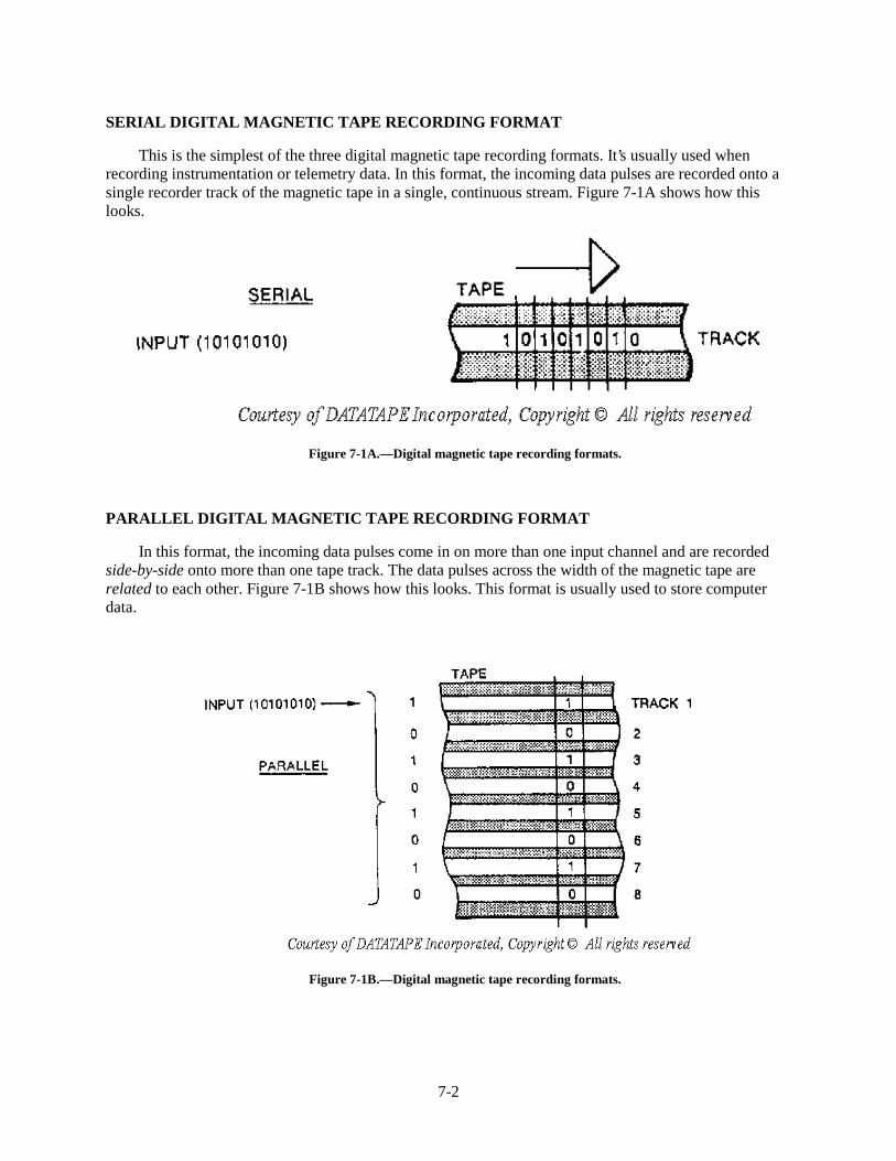
7-2
SERIAL DIGITAL MAGNETIC TAPE RECORDING FORMAT
This is the simplest of the three digital magnetic tape recording formats. It’s usually used whenrecording instrumentation or telemetry data. In this format, the incoming data pulses are recorded onto asingle recorder track of the magnetic tape in a single, continuous stream. Figure 7-1A shows how thislooks.
Figure 7-1A.—Digital magnetic tape recording formats.
PARALLEL DIGITAL MAGNETIC TAPE RECORDING FORMAT
In this format, the incoming data pulses come in on more than one input channel and are recordedside-by-side onto more than one tape track. The data pulses across the width of the magnetic tape arerelated to each other. Figure 7-1B shows how this looks. This format is usually used to store computerdata.
Figure 7-1B.—Digital magnetic tape recording formats.
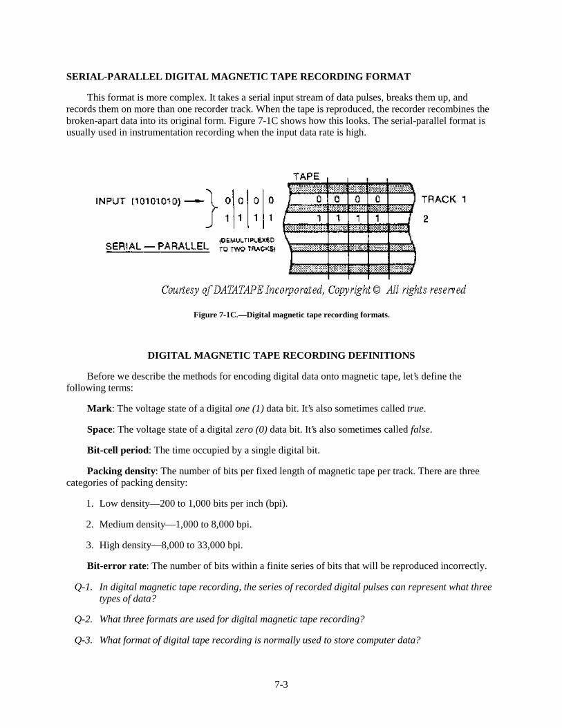
7-3
SERIAL-PARALLEL DIGITAL MAGNETIC TAPE RECORDING FORMAT
This format is more complex. It takes a serial input stream of data pulses, breaks them up, andrecords them on more than one recorder track. When the tape is reproduced, the recorder recombines thebroken-apart data into its original form. Figure 7-1C shows how this looks. The serial-parallel format isusually used in instrumentation recording when the input data rate is high.
Figure 7-1C.—Digital magnetic tape recording formats.
DIGITAL MAGNETIC TAPE RECORDING DEFINITIONS
Before we describe the methods for encoding digital data onto magnetic tape, let’s define thefollowing terms:
Mark: The voltage state of a digital one (1) data bit. It’s also sometimes called true.
Space: The voltage state of a digital zero (0) data bit. It’s also sometimes called false.
Bit-cell period: The time occupied by a single digital bit.
Packing density: The number of bits per fixed length of magnetic tape per track. There are threecategories of packing density:
1. Low density—200 to 1,000 bits per inch (bpi).
2. Medium density—1,000 to 8,000 bpi.
3. High density—8,000 to 33,000 bpi.
Bit-error rate: The number of bits within a finite series of bits that will be reproduced incorrectly.
Q-1. In digital magnetic tape recording, the series of recorded digital pulses can represent what threetypes of data?
Q-2. What three formats are used for digital magnetic tape recording?
Q-3. What format of digital tape recording is normally used to store computer data?
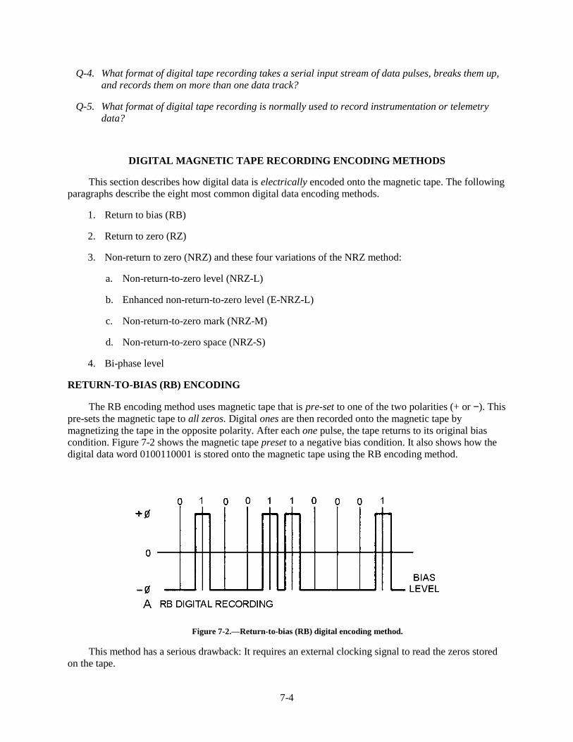
7-4
Q-4. What format of digital tape recording takes a serial input stream of data pulses, breaks them up,and records them on more than one data track?
Q-5. What format of digital tape recording is normally used to record instrumentation or telemetrydata?
DIGITAL MAGNETIC TAPE RECORDING ENCODING METHODS
This section describes how digital data is electrically encoded onto the magnetic tape. The followingparagraphs describe the eight most common digital data encoding methods.
1. Return to bias (RB)
2. Return to zero (RZ)
3. Non-return to zero (NRZ) and these four variations of the NRZ method:
a. Non-return-to-zero level (NRZ-L)
b. Enhanced non-return-to-zero level (E-NRZ-L)
c. Non-return-to-zero mark (NRZ-M)
d. Non-return-to-zero space (NRZ-S)
4. Bi-phase level
RETURN-TO-BIAS (RB) ENCODING
The RB encoding method uses magnetic tape that is pre-set to one of the two polarities (+ or −). Thispre-sets the magnetic tape to all zeros. Digital ones are then recorded onto the magnetic tape bymagnetizing the tape in the opposite polarity. After each one pulse, the tape returns to its original biascondition. Figure 7-2 shows the magnetic tape preset to a negative bias condition. It also shows how thedigital data word 0100110001 is stored onto the magnetic tape using the RB encoding method.
Figure 7-2.—Return-to-bias (RB) digital encoding method.
This method has a serious drawback: It requires an external clocking signal to read the zeros storedon the tape.
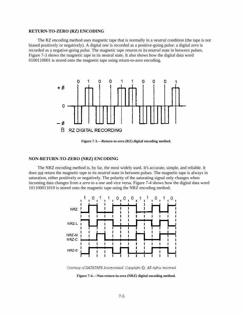
7-5
RETURN-TO-ZERO (RZ) ENCODING
The RZ encoding method uses magnetic tape that is normally in a neutral condition (the tape is notbiased positively or negatively). A digital one is recorded as a positive-going pulse: a digital zero isrecorded as a negative-going pulse. The magnetic tape returns to its neutral state in between pulses.Figure 7-3 shows the magnetic tape in its neutral state. It also shows how the digital data word0100110001 is stored onto the magnetic tape using return-to-zero encoding.
Figure 7-3.—Return-to-zero (RZ) digital encoding method.
NON-RETURN-TO-ZERO (NRZ) ENCODING
The NRZ encoding method is, by far, the most widely used. It’s accurate, simple, and reliable. Itdoes not return the magnetic tape to its neutral state in between pulses. The magnetic tape is always insaturation, either positively or negatively. The polarity of the saturating signal only changes whenincoming data changes from a zero to a one and vice versa. Figure 7-4 shows how the digital data word101100011010 is stored onto the magnetic tape using the NRZ encoding method.
Figure 7-4.—Non-return-to-zero (NRZ) digital encoding method.
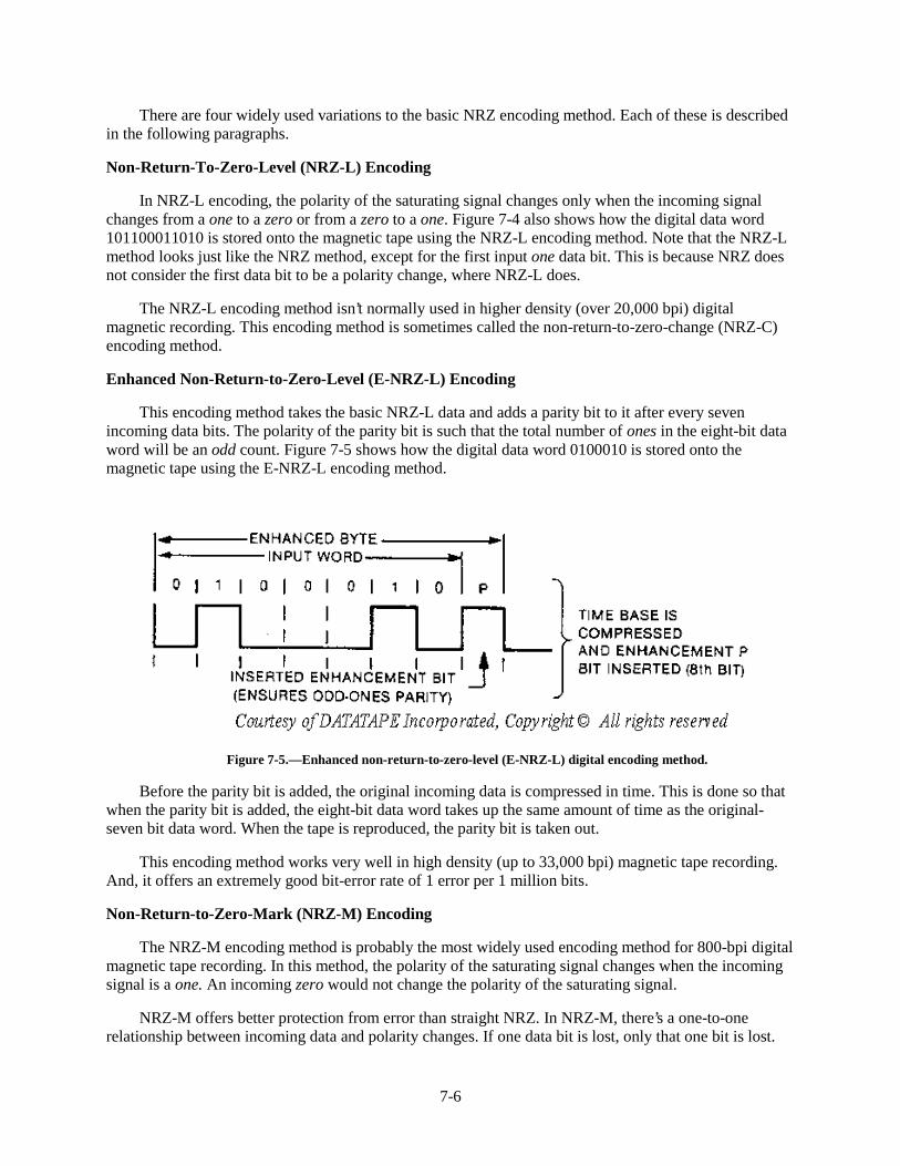
7-6
There are four widely used variations to the basic NRZ encoding method. Each of these is describedin the following paragraphs.
Non-Return-To-Zero-Level (NRZ-L) Encoding
In NRZ-L encoding, the polarity of the saturating signal changes only when the incoming signalchanges from a one to a zero or from a zero to a one. Figure 7-4 also shows how the digital data word101100011010 is stored onto the magnetic tape using the NRZ-L encoding method. Note that the NRZ-Lmethod looks just like the NRZ method, except for the first input one data bit. This is because NRZ doesnot consider the first data bit to be a polarity change, where NRZ-L does.
The NRZ-L encoding method isn’t normally used in higher density (over 20,000 bpi) digitalmagnetic recording. This encoding method is sometimes called the non-return-to-zero-change (NRZ-C)encoding method.
Enhanced Non-Return-to-Zero-Level (E-NRZ-L) Encoding
This encoding method takes the basic NRZ-L data and adds a parity bit to it after every sevenincoming data bits. The polarity of the parity bit is such that the total number of ones in the eight-bit dataword will be an odd count. Figure 7-5 shows how the digital data word 0100010 is stored onto themagnetic tape using the E-NRZ-L encoding method.
Figure 7-5.—Enhanced non-return-to-zero-level (E-NRZ-L) digital encoding method.
Before the parity bit is added, the original incoming data is compressed in time. This is done so thatwhen the parity bit is added, the eight-bit data word takes up the same amount of time as the original-seven bit data word. When the tape is reproduced, the parity bit is taken out.
This encoding method works very well in high density (up to 33,000 bpi) magnetic tape recording.And, it offers an extremely good bit-error rate of 1 error per 1 million bits.
Non-Return-to-Zero-Mark (NRZ-M) Encoding
The NRZ-M encoding method is probably the most widely used encoding method for 800-bpi digitalmagnetic tape recording. In this method, the polarity of the saturating signal changes when the incomingsignal is a one. An incoming zero would not change the polarity of the saturating signal.
NRZ-M offers better protection from error than straight NRZ. In NRZ-M, there’s a one-to-onerelationship between incoming data and polarity changes. If one data bit is lost, only that one bit is lost.
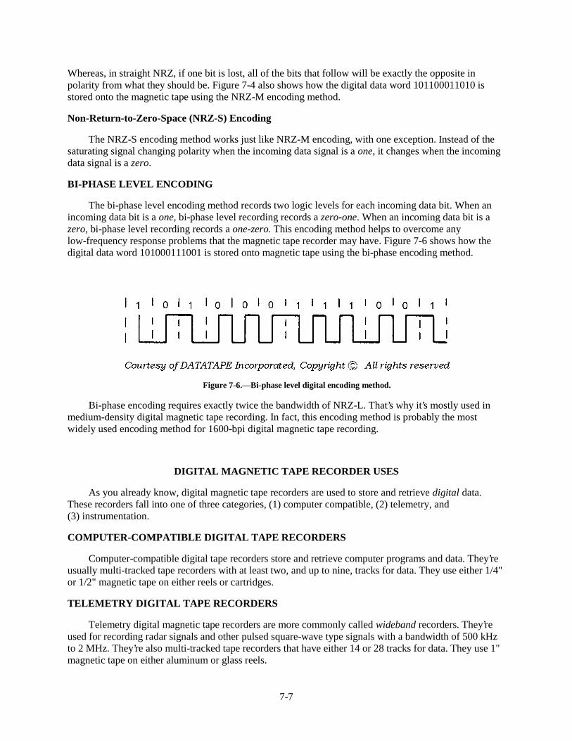
7-7
Whereas, in straight NRZ, if one bit is lost, all of the bits that follow will be exactly the opposite inpolarity from what they should be. Figure 7-4 also shows how the digital data word 101100011010 isstored onto the magnetic tape using the NRZ-M encoding method.
Non-Return-to-Zero-Space (NRZ-S) Encoding
The NRZ-S encoding method works just like NRZ-M encoding, with one exception. Instead of thesaturating signal changing polarity when the incoming data signal is a one, it changes when the incomingdata signal is a zero.
BI-PHASE LEVEL ENCODING
The bi-phase level encoding method records two logic levels for each incoming data bit. When anincoming data bit is a one, bi-phase level recording records a zero-one. When an incoming data bit is azero, bi-phase level recording records a one-zero. This encoding method helps to overcome anylow-frequency response problems that the magnetic tape recorder may have. Figure 7-6 shows how thedigital data word 101000111001 is stored onto magnetic tape using the bi-phase encoding method.
Figure 7-6.—Bi-phase level digital encoding method.
Bi-phase encoding requires exactly twice the bandwidth of NRZ-L. That’s why it’s mostly used inmedium-density digital magnetic tape recording. In fact, this encoding method is probably the mostwidely used encoding method for 1600-bpi digital magnetic tape recording.
DIGITAL MAGNETIC TAPE RECORDER USES
As you already know, digital magnetic tape recorders are used to store and retrieve digital data.These recorders fall into one of three categories, (1) computer compatible, (2) telemetry, and(3) instrumentation.
COMPUTER-COMPATIBLE DIGITAL TAPE RECORDERS
Computer-compatible digital tape recorders store and retrieve computer programs and data. They’reusually multi-tracked tape recorders with at least two, and up to nine, tracks for data. They use either 1/4"or 1/2" magnetic tape on either reels or cartridges.
TELEMETRY DIGITAL TAPE RECORDERS
Telemetry digital magnetic tape recorders are more commonly called wideband recorders. They’reused for recording radar signals and other pulsed square-wave type signals with a bandwidth of 500 kHzto 2 MHz. They’re also multi-tracked tape recorders that have either 14 or 28 tracks for data. They use 1"magnetic tape on either aluminum or glass reels.
7-8
INSTRUMENTATION MAGNETIC TAPE RECORDERS
Instrumentation digital magnetic tape recorders are used to record other special signals with abandwidth of less than 500 kHz. They, too, are multi-tracked recorders, normally with 7 tracks for data.They use 1/2" magnetic tape on metal or glass reels.
Q-6. Which of the eight methods for encoding digital data onto magnetic tape is most widely usedbecause it’s accurate, simple, and reliable?
Q-7. Which digital data tape encoding method presets the magnetic tape to all zeros and then recordsdigital ones onto the tape?
Q-8. Which digital data encoding method records a digital one as a positive pulse and a digital (zero)as a negative pulse and returns the tape to neutral between pulses?
Q-9. Which method of digital data encoding does NOT return the tape to neutral between pulses but,instead, saturates the tape positively or negatively as the incoming data changes between zeroand one?
Q-10. What are the four widely used variations of the NRZ encoding method?
Q-11. Which digital data encoding method helps overcome a tape recorder’s low-frequency responseproblems by recording two logic levels for each incoming data bit?
Q-12. Digital magnetic tape recorders used to store and retrieve digital data fall into what threecategories?
Q-13. What category of digital tape recorder is used for recording pulsed square-wave signals with abandwidth of 500 kHz to 2 MHz?
Q-14. What category of digital tape recorder is used to record special signals with a bandwidth of lessthan 500 kHz?
SUMMARY
Now that you’ve finished chapter 7, you should be able to describe (1) the characteristics of digitalmagnetic tape recording, (2) the three formats for digital magnetic tape recording, (3) the eight methodsfor encoding digital data onto magnetic tape, and (4) the characteristics and uses of the three types ofdigital magnetic tape recorders. The following is a summary of important points in this chapter:
Digital magnetic tape recorders record a SERIES OF DIGITAL PULSES called binary ones andzeros. These digital pulses can represent (1) data used by digital computers, (2) pulsed square-wavesignals, or (3) digitized analog waveforms.
Three FORMATS FOR DIGITAL MAGNETIC TAPE RECORDING are serial, parallel, andserial-parallel.
There are EIGHT COMMONLY USED METHODS FOR ENCODING digital data ontomagnetic tape. The non-return-to-zero (NRZ) method and the four variations of the NRZ method are mostcommonly used.
7-9
THREE CATEGORIES OF DIGITAL MAGNETIC TAPE RECORDERS are (1) computer-compatible, (2) telemetry, and (3) instrumentation.
ANSWERS TO QUESTIONS Q1. THROUGH Q14.
A1.
a. Data used by digital computers.
b. Pulsed squarewave signals.
c. Digitized analog waveforms.
A2. (1) Serial, (2) parallel, and (3) serial-parallel.
A3. Parallel digital magnetic tape recording.
A4. Serial-parallel digital magnetic tape recording.
A5. Serial digital magnetic tape recording.
A6. Non-return-to-zero (NRZ) encoding.
A7. Return-to-bias (RB) encoding.
A8. Return-to-zero (RZ) encoding.
A9. Non-return-to-zero (NRZ) encoding.
A10.
a. Non-return-to-zero level (NRZ-L).
b. Enhanced non-return-to-zero level (E-NRZ-L).
c. Non-return-to-zero mark (NRZ-M).
d. Non-return-to-zero space (NRZ-S).
A11. Bi-phase level encoding.
A12.
a. Computer-compatible digital tape recorders.
b. Telemetry digital tape recorders.
c. Instrumentation digital tape recorders.
A13. Telemetry digital tape recorders.
A14. Instrumentation digital tape recorders.

8-1
CHAPTER 8
MAGNETIC DISK RECORDING
LEARNING OBJECTIVES
After completing this chapter, you'll be able to do the following:
1. Describe how flexible (floppy) disks are constructed; how data is organized on them; how they are handled, stored, and shipped; and how they are erased.
2. Describe how fixed (hard) disks are constructed; how data is organized on them; how they are handled, stored, and shipped; and how they are erased.
3. Describe each of the following methods for recording (encoding) digital data onto magnetic disks: frequency-modulation encoding, modified frequency-modulation encoding, and run length-limited encoding.
4. Describe the characteristics of floppy disk drive transports and hard disk drive transports and describe the preventive maintenance requirements of each type.
5. Describe the following parts of the electronics component of a magnetic disk drive: control electronics, write/read electronics, and interface electronics.
6. Describe the five most common types of disk drive interface electronics.
7. Define the following magnetic disk recording specifications: seek time, latency period, access time, interleave factor, transfer rate, and recording density.
INTRODUCTION
Magnetic disk recording was invented by International Business Machines (IBM) in 1956. It was developed to allow mainframe computers to store large amounts of computer programs and data. This new technology eventually led to what's now known as the computer revolution.
This chapter introduces you to the following aspects of magnetic disk recording:
• Disk recording mediums
• Disk recording methods
• Disk drive transports
• Disk drive electronics
• Disk recording specifications
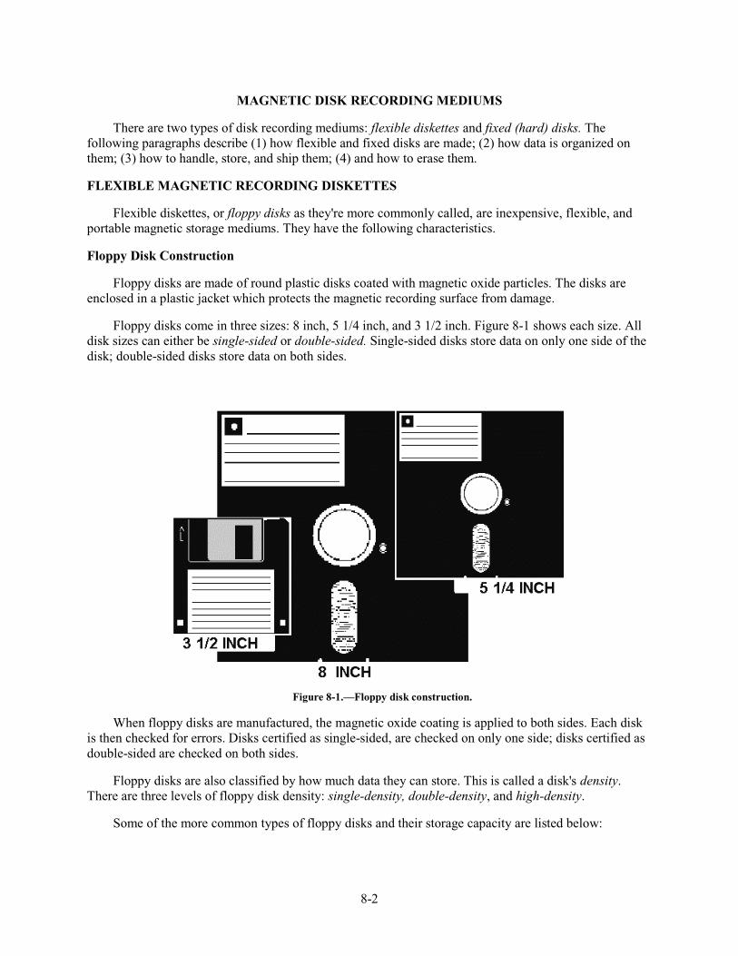
8-2
MAGNETIC DISK RECORDING MEDIUMS
There are two types of disk recording mediums: flexible diskettes and fixed (hard) disks. The following paragraphs describe (1) how flexible and fixed disks are made; (2) how data is organized on them; (3) how to handle, store, and ship them; (4) and how to erase them.
FLEXIBLE MAGNETIC RECORDING DISKETTES
Flexible diskettes, or floppy disks as they're more commonly called, are inexpensive, flexible, and portable magnetic storage mediums. They have the following characteristics.
Floppy Disk Construction
Floppy disks are made of round plastic disks coated with magnetic oxide particles. The disks are enclosed in a plastic jacket which protects the magnetic recording surface from damage.
Floppy disks come in three sizes: 8 inch, 5 1/4 inch, and 3 1/2 inch. Figure 8-1 shows each size. All disk sizes can either be single-sided or double-sided. Single-sided disks store data on only one side of the disk; double-sided disks store data on both sides.
Figure 8-1.—Floppy disk construction.
When floppy disks are manufactured, the magnetic oxide coating is applied to both sides. Each disk is then checked for errors. Disks certified as single-sided, are checked on only one side; disks certified as double-sided are checked on both sides.
Floppy disks are also classified by how much data they can store. This is called a disk's density. There are three levels of floppy disk density: single-density, double-density, and high-density.
Some of the more common types of floppy disks and their storage capacity are listed below:
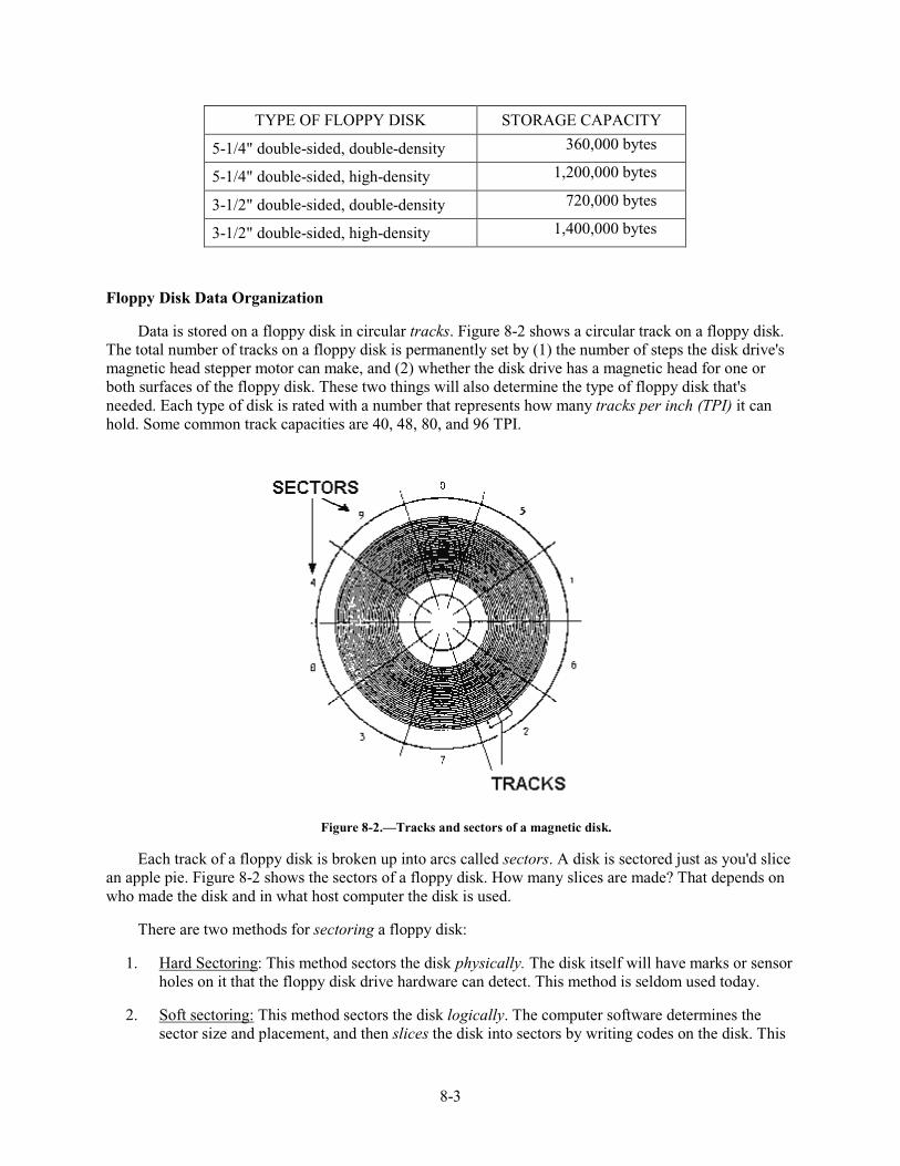
8-3
TYPE OF FLOPPY DISK STORAGE CAPACITY
5-1/4" double-sided, double-density 360,000 bytes
5-1/4" double-sided, high-density 1,200,000 bytes
3-1/2" double-sided, double-density 720,000 bytes
3-1/2" double-sided, high-density 1,400,000 bytes
Floppy Disk Data Organization
Data is stored on a floppy disk in circular tracks. Figure 8-2 shows a circular track on a floppy disk. The total number of tracks on a floppy disk is permanently set by (1) the number of steps the disk drive's magnetic head stepper motor can make, and (2) whether the disk drive has a magnetic head for one or both surfaces of the floppy disk. These two things will also determine the type of floppy disk that's needed. Each type of disk is rated with a number that represents how many tracks per inch (TPI) it can hold. Some common track capacities are 40, 48, 80, and 96 TPI.
Figure 8-2.—Tracks and sectors of a magnetic disk.
Each track of a floppy disk is broken up into arcs called sectors. A disk is sectored just as you'd slice an apple pie. Figure 8-2 shows the sectors of a floppy disk. How many slices are made? That depends on who made the disk and in what host computer the disk is used.
There are two methods for sectoring a floppy disk:
1. Hard Sectoring: This method sectors the disk physically. The disk itself will have marks or sensor holes on it that the floppy disk drive hardware can detect. This method is seldom used today.
2. Soft sectoring: This method sectors the disk logically. The computer software determines the sector size and placement, and then slices the disk into sectors by writing codes on the disk. This
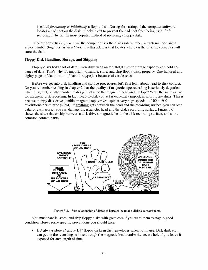
8-4
is called formatting or initializing a floppy disk. During formatting, if the computer software locates a bad spot on the disk, it locks it out to prevent the bad spot from being used. Soft sectoring is by far the most popular method of sectoring a floppy disk.
Once a floppy disk is formatted, the computer uses the disk's side number, a track number, and a sector number (together) as an address. It's this address that locates where on the disk the computer will store the data.
Floppy Disk Handling, Storage, and Shipping
Floppy disks hold a lot of data. Even disks with only a 360,000-byte storage capacity can hold 180 pages of data! That's why it's important to handle, store, and ship floppy disks properly. One hundred and eighty pages of data is a lot of data to retype just because of carelessness.
Before we get into disk handling and storage procedures, let's first learn about head-to-disk contact. Do you remember reading in chapter 2 that the quality of magnetic tape recording is seriously degraded when dust, dirt, or other contaminates get between the magnetic head and the tape? Well, the same is true for magnetic disk recording. In fact, head-to-disk contact is extremely important with floppy disks. This is because floppy disk drives, unlike magnetic tape drives, spin at very high speeds — 300 to 600 revolutions-per-minute (RPM). If anything gets between the head and the recording surface, you can lose data, or even worse, you can damage the magnetic head and the disk's recording surface. Figure 8-3 shows the size relationship between a disk drive's magnetic head, the disk recording surface, and some common contaminants.
Figure 8-3.—Size relationship of distance between head and disk to contaminants.
You must handle, store, and ship floppy disks with great care if you want them to stay in good condition. Here's some specific precautions you should take:
• DO always store 8" and 5-1/4" floppy disks in their envelopes when not in use. Dirt, dust, etc., can get on the recording surface through the magnetic head read/write access hole if you leave it exposed for any length of time.
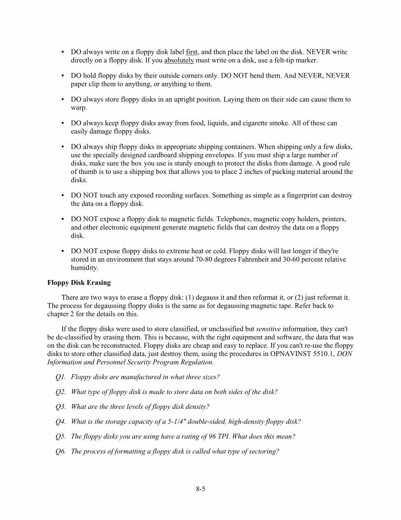
8-5
• DO always write on a floppy disk label first, and then place the label on the disk. NEVER write directly on a floppy disk. If you absolutely must write on a disk, use a felt-tip marker.
• DO hold floppy disks by their outside corners only. DO NOT bend them. And NEVER, NEVER paper clip them to anything, or anything to them.
• DO always store floppy disks in an upright position. Laying them on their side can cause them to warp.
• DO always keep floppy disks away from food, liquids, and cigarette smoke. All of these can easily damage floppy disks.
• DO always ship floppy disks in appropriate shipping containers. When shipping only a few disks, use the specially designed cardboard shipping envelopes. If you must ship a large number of disks, make sure the box you use is sturdy enough to protect the disks from damage. A good rule of thumb is to use a shipping box that allows you to place 2 inches of packing material around the disks.
• DO NOT touch any exposed recording surfaces. Something as simple as a fingerprint can destroy the data on a floppy disk.
• DO NOT expose a floppy disk to magnetic fields. Telephones, magnetic copy holders, printers, and other electronic equipment generate magnetic fields that can destroy the data on a floppy disk.
• DO NOT expose floppy disks to extreme heat or cold. Floppy disks will last longer if they're stored in an environment that stays around 70-80 degrees Fahrenheit and 30-60 percent relative humidity.
Floppy Disk Erasing
There are two ways to erase a floppy disk: (1) degauss it and then reformat it, or (2) just reformat it. The process for degaussing floppy disks is the same as for degaussing magnetic tape. Refer back to chapter 2 for the details on this.
If the floppy disks were used to store classified, or unclassified but sensitive information, they can't be de-classified by erasing them. This is because, with the right equipment and software, the data that was on the disk can be reconstructed. Floppy disks are cheap and easy to replace. If you can't re-use the floppy disks to store other classified data, just destroy them, using the procedures in OPNAVINST 5510.1, DON Information and Personnel Security Program Regulation.
Q1. Floppy disks are manufactured in what three sizes?
Q2. What type of floppy disk is made to store data on both sides of the disk?
Q3. What are the three levels of floppy disk density?
Q4. What is the storage capacity of a 5-1/4" double-sided, high-density floppy disk?
Q5. The floppy disks you are using have a rating of 96 TPI. What does this mean?
Q6. The process of formatting a floppy disk is called what type of sectoring?
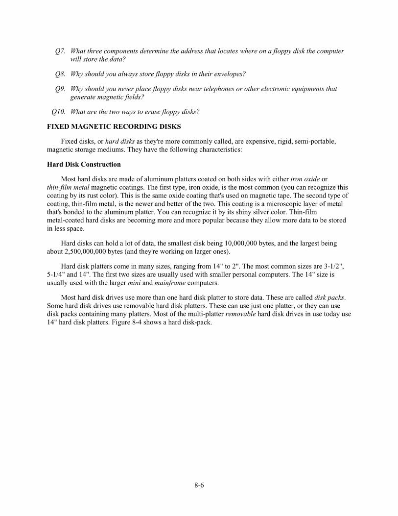
8-6
Q7. What three components determine the address that locates where on a floppy disk the computer will store the data?
Q8. Why should you always store floppy disks in their envelopes?
Q9. Why should you never place floppy disks near telephones or other electronic equipments that generate magnetic fields?
Q10. What are the two ways to erase floppy disks?
FIXED MAGNETIC RECORDING DISKS
Fixed disks, or hard disks as they're more commonly called, are expensive, rigid, semi-portable, magnetic storage mediums. They have the following characteristics:
Hard Disk Construction
Most hard disks are made of aluminum platters coated on both sides with either iron oxide or thin-film metal magnetic coatings. The first type, iron oxide, is the most common (you can recognize this coating by its rust color). This is the same oxide coating that's used on magnetic tape. The second type of coating, thin-film metal, is the newer and better of the two. This coating is a microscopic layer of metal that's bonded to the aluminum platter. You can recognize it by its shiny silver color. Thin-film metal-coated hard disks are becoming more and more popular because they allow more data to be stored in less space.
Hard disks can hold a lot of data, the smallest disk being 10,000,000 bytes, and the largest being about 2,500,000,000 bytes (and they're working on larger ones).
Hard disk platters come in many sizes, ranging from 14" to 2". The most common sizes are 3-1/2", 5-1/4" and 14". The first two sizes are usually used with smaller personal computers. The 14" size is usually used with the larger mini and mainframe computers.
Most hard disk drives use more than one hard disk platter to store data. These are called disk packs. Some hard disk drives use removable hard disk platters. These can use just one platter, or they can use disk packs containing many platters. Most of the multi-platter removable hard disk drives in use today use 14" hard disk platters. Figure 8-4 shows a hard disk-pack.
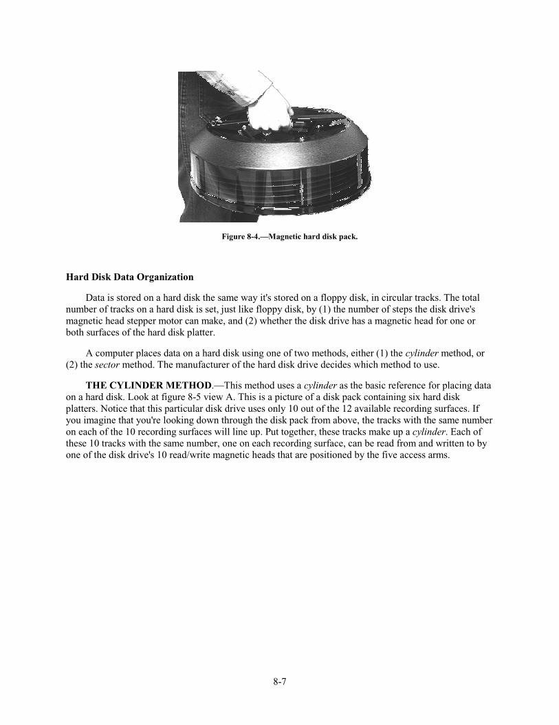
8-7
Figure 8-4.—Magnetic hard disk pack.
Hard Disk Data Organization
Data is stored on a hard disk the same way it's stored on a floppy disk, in circular tracks. The total number of tracks on a hard disk is set, just like floppy disk, by (1) the number of steps the disk drive's magnetic head stepper motor can make, and (2) whether the disk drive has a magnetic head for one or both surfaces of the hard disk platter.
A computer places data on a hard disk using one of two methods, either (1) the cylinder method, or (2) the sector method. The manufacturer of the hard disk drive decides which method to use.
THE CYLINDER METHOD.—This method uses a cylinder as the basic reference for placing data on a hard disk. Look at figure 8-5 view A. This is a picture of a disk pack containing six hard disk platters. Notice that this particular disk drive uses only 10 out of the 12 available recording surfaces. If you imagine that you're looking down through the disk pack from above, the tracks with the same number on each of the 10 recording surfaces will line up. Put together, these tracks make up a cylinder. Each of these 10 tracks with the same number, one on each recording surface, can be read from and written to by one of the disk drive's 10 read/write magnetic heads that are positioned by the five access arms.
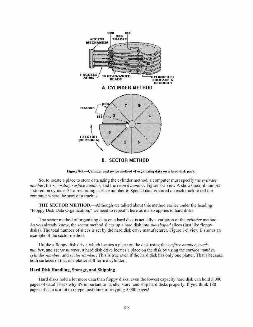
8-8
Figure 8-5.—Cylinder and sector method of organizing data on a hard disk pack.
So, to locate a place to store data using the cylinder method, a computer must specify the cylinder number, the recording surface number, and the record number. Figure 8-5 view A shows record number 1 stored on cylinder 25 of recording surface number 6. Special data is stored on each track to tell the computer where the start of a track is.
THE SECTOR METHOD.—Although we talked about this method earlier under the heading "Floppy Disk Data Organization," we need to repeat it here as it also applies to hard disks.
The sector method of organizing data on a hard disk is actually a variation of the cylinder method. As you already know, the sector method slices up a hard disk into pie-shaped slices (just like floppy disks). The total number of slices is set by the hard disk drive manufacturer. Figure 8-5 view B shows an example of the sector method.
Unlike a floppy disk drive, which locates a place on the disk using the surface number, track number, and sector number, a hard disk drive locates a place on the disk by using the surface number, cylinder number, and sector number. This is true even if the hard disk has only one platter. That's because both surfaces of that one platter still form a cylinder.
Hard Disk Handling, Storage, and Shipping
Hard disks hold a lot more data than floppy disks; even the lowest capacity hard disk can hold 5,000 pages of data! That's why it's important to handle, store, and ship hard disks properly. If you think 180 pages of data is a lot to retype, just think of retyping 5,000 pages!
8-9
Hard disk drives spin at a very high speed of about 3600 RPM. It is extremely important that nothing gets between the head and the recording surface. If it does, you can lose data and you can damage both the magnetic head and the disk's recording surface.
Most hard disk failures involve a head-crash. It's the worst thing that can happen to a hard disk. A head-crash is the result of the disk drive's magnetic heads crashing into the recording surface and grinding into the hard disk platter. Figure 8-6 shows a good hard disk platter and a bad hard disk platter that was the victim of a head-crash.
Figure 8-6.—Example of a hard disk crash.
You must handle, store, and ship hard disks with extreme care if you want them to stay in good condition. Here are some specific precautions you should take:
• DO always store removable hard disks in their storage cases when not in use. Dirt, dust, etc., can get on the recording surface through the magnetic head read/write access hole if you leave it exposed for any length of time.
• DO always handle hard disks with extreme care. DO NOT drop them. Even a small drop of 2" can warp a hard disk platter enough to cause a head crash.
• DO always keep removable hard disks away from food, liquids, and cigarette smoke. All of these can easily cause damage.
• DO always ship hard disks in their proper shipping containers. If you don't have the original shipping container, make sure the shipping box is sturdy and big enough to allow 2" of packing material around the disk. Save the original packing material for the hard disk just in case you need to ship it somewhere.
• DO NOT touch any exposed recording surfaces. Something as simple as a fingerprint can cause a head crash and destroy a hard disk platter.
• DO NOT expose hard disks to extreme heat or cold. Hard disks will last longer if they're stored in an environment that stays around 70-80 degrees Fahrenheit and 30-60 percent relative humidity.
Hard Disk Erasing
There are two ways to erase a hard disk: (1) degauss it and then reformat it, or (2) just reformat it. As you might guess, the first method can only be used for removable hard disk platters. The second method
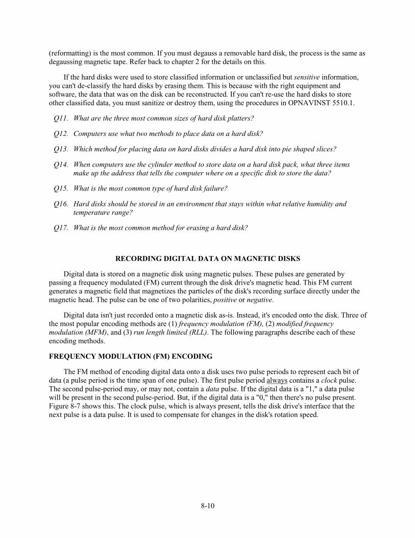
8-10
(reformatting) is the most common. If you must degauss a removable hard disk, the process is the same as degaussing magnetic tape. Refer back to chapter 2 for the details on this.
If the hard disks were used to store classified information or unclassified but sensitive information, you can't de-classify the hard disks by erasing them. This is because with the right equipment and software, the data that was on the disk can be reconstructed. If you can't re-use the hard disks to store other classified data, you must sanitize or destroy them, using the procedures in OPNAVINST 5510.1.
Q11. What are the three most common sizes of hard disk platters?
Q12. Computers use what two methods to place data on a hard disk?
Q13. Which method for placing data on hard disks divides a hard disk into pie shaped slices?
Q14. When computers use the cylinder method to store data on a hard disk pack, what three items make up the address that tells the computer where on a specific disk to store the data?
Q15. What is the most common type of hard disk failure?
Q16. Hard disks should be stored in an environment that stays within what relative humidity and temperature range?
Q17. What is the most common method for erasing a hard disk?
RECORDING DIGITAL DATA ON MAGNETIC DISKS
Digital data is stored on a magnetic disk using magnetic pulses. These pulses are generated by passing a frequency modulated (FM) current through the disk drive's magnetic head. This FM current generates a magnetic field that magnetizes the particles of the disk's recording surface directly under the magnetic head. The pulse can be one of two polarities, positive or negative.
Digital data isn't just recorded onto a magnetic disk as-is. Instead, it's encoded onto the disk. Three of the most popular encoding methods are (1) frequency modulation (FM), (2) modified frequency modulation (MFM), and (3) run length limited (RLL). The following paragraphs describe each of these encoding methods.
FREQUENCY MODULATION (FM) ENCODING
The FM method of encoding digital data onto a disk uses two pulse periods to represent each bit of data (a pulse period is the time span of one pulse). The first pulse period always contains a clock pulse. The second pulse-period may, or may not, contain a data pulse. If the digital data is a "1," a data pulse will be present in the second pulse-period. But, if the digital data is a "0," then there's no pulse present. Figure 8-7 shows this. The clock pulse, which is always present, tells the disk drive's interface that the next pulse is a data pulse. It is used to compensate for changes in the disk's rotation speed.
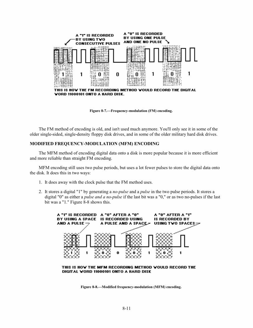
8-11
Figure 8-7.—Frequency-modulation (FM) encoding.
The FM method of encoding is old, and isn't used much anymore. You'll only see it in some of the older single-sided, single-density floppy disk drives, and in some of the older military hard disk drives.
MODIFIED FREQUENCY-MODULATION (MFM) ENCODING
The MFM method of encoding digital data onto a disk is more popular because it is more efficient and more reliable than straight FM encoding.
MFM encoding still uses two pulse periods, but uses a lot fewer pulses to store the digital data onto the disk. It does this in two ways:
1. It does away with the clock pulse that the FM method uses.
2. It stores a digital "1" by generating a no-pulse and a pulse in the two pulse periods. It stores a digital "0" as either a pulse and a no-pulse if the last bit was a "0," or as two no-pulses if the last bit was a "1." Figure 8-8 shows this.
Figure 8-8.—Modified frequency-modulation (MFM) encoding.
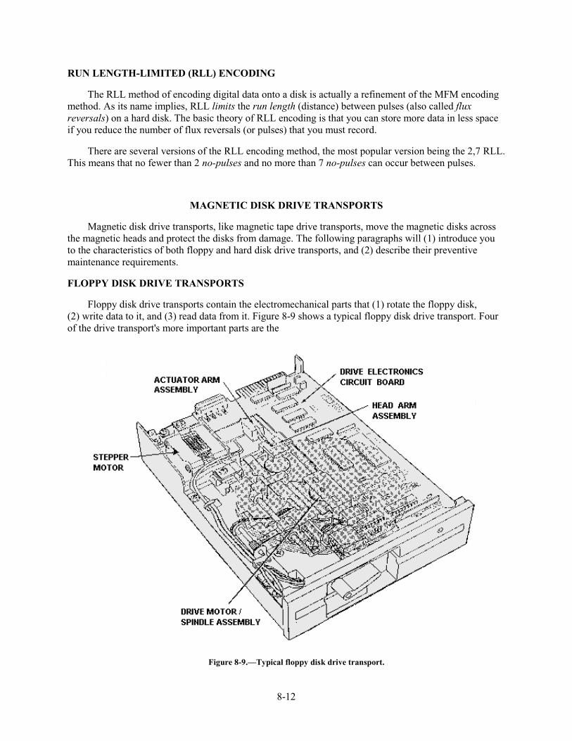
8-12
RUN LENGTH-LIMITED (RLL) ENCODING
The RLL method of encoding digital data onto a disk is actually a refinement of the MFM encoding method. As its name implies, RLL limits the run length (distance) between pulses (also called flux reversals) on a hard disk. The basic theory of RLL encoding is that you can store more data in less space if you reduce the number of flux reversals (or pulses) that you must record.
There are several versions of the RLL encoding method, the most popular version being the 2,7 RLL. This means that no fewer than 2 no-pulses and no more than 7 no-pulses can occur between pulses.
MAGNETIC DISK DRIVE TRANSPORTS
Magnetic disk drive transports, like magnetic tape drive transports, move the magnetic disks across the magnetic heads and protect the disks from damage. The following paragraphs will (1) introduce you to the characteristics of both floppy and hard disk drive transports, and (2) describe their preventive maintenance requirements.
FLOPPY DISK DRIVE TRANSPORTS
Floppy disk drive transports contain the electromechanical parts that (1) rotate the floppy disk, (2) write data to it, and (3) read data from it. Figure 8-9 shows a typical floppy disk drive transport. Four of the drive transport's more important parts are the
Figure 8-9.—Typical floppy disk drive transport.
8-13
1. drive motor/spindle assembly,
2. head arm assembly,
3. actuator arm assembly, and
4. drive electronics circuit board.
Drive Motor/Spindle Assembly
The spindle in this assembly holds the floppy disk in place while it spins. The drive motor spins the spindle at 300 to 600 RPM, depending on the type of floppy disk drive. The following is a list of the types of floppy disk drives and the spinning speeds of their spindles.
FLOPPY DISK DRIVE TYPE SPINNING SPEED
5-1/4" 360-KB storage 300 RPM
5-1/4" 1.2-MB storage 360 RPM
3-1/2" 720-KB storage 600 RPM
3-1/2" 1.44-MB storage 600 RPM
The spindle of a 5-1/4" disk drive is activated and released by a small arm that's mounted on the front of the disk drive. You must turn the small arm to lock and release the floppy disk.
The spindle of a 3-1/2" disk drive is activated when the floppy disk is inserted into the disk drive. It's released by a push-button that's located on the front of the disk drive. When you push this button, the floppy disk is released and pops out of the disk drive.
Head Arm Assembly
This part of a floppy disk drive transport holds the magnetic read/write heads. There are four heads on a head arm assembly, two write heads and two read heads - one of each for each recording surface. The head arm assembly is attached to the actuator arm assembly.
Actuator Arm Assembly
The actuator arm assembly positions the magnetic heads over the recording surface of the floppy disk. It does this by using a special type of dc motor called a stepper motor. This motor, which can be moved in very small steps, allows the read/write heads to be moved from track to track as needed to write data onto and read data off of the floppy disk.
Drive Electronics Circuit Board
This circuit board contains the circuitry which (1) controls the electromechanical parts of the disk drive transport, (2) writes data to and reads data from the floppy disk, and (3) interfaces the floppy disk drive to the host computer.
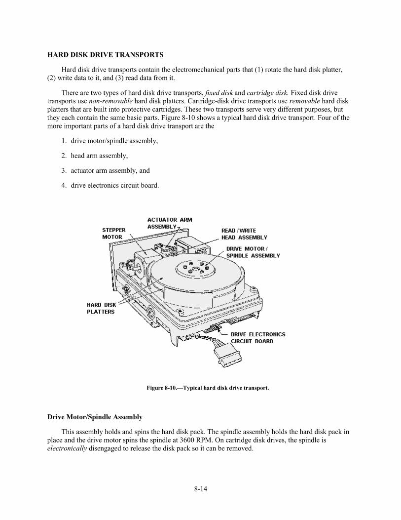
8-14
HARD DISK DRIVE TRANSPORTS
Hard disk drive transports contain the electromechanical parts that (1) rotate the hard disk platter, (2) write data to it, and (3) read data from it.
There are two types of hard disk drive transports, fixed disk and cartridge disk. Fixed disk drive transports use non-removable hard disk platters. Cartridge-disk drive transports use removable hard disk platters that are built into protective cartridges. These two transports serve very different purposes, but they each contain the same basic parts. Figure 8-10 shows a typical hard disk drive transport. Four of the more important parts of a hard disk drive transport are the
1. drive motor/spindle assembly,
2. head arm assembly,
3. actuator arm assembly, and
4. drive electronics circuit board.
Figure 8-10.—Typical hard disk drive transport.
Drive Motor/Spindle Assembly
This assembly holds and spins the hard disk pack. The spindle assembly holds the hard disk pack in place and the drive motor spins the spindle at 3600 RPM. On cartridge disk drives, the spindle is electronically disengaged to release the disk pack so it can be removed.
8-15
Head Arm Assembly
This part of the hard disk drive transport holds the magnetic read/write heads. There is a separate head arm assembly for each of the hard disk platters in the disk pack. Each assembly has four magnetic heads, two write heads and two read heads-one pair of heads for each surface of the hard disk platter. The head arm assembly is attached to the actuator arm assembly.
Actuator Arm Assembly
This part of the hard disk drive transport positions the magnetic heads so they can write data to and read data from the correct track of the hard disk. It does this by using either a stepper motor or a voice coil servo. A stepper motor is a special type of dc motor which can be moved in very small steps to accurately position the magnetic heads. A voice coil servo by itself cannot move the magnetic heads from track to track. Instead, it must use special signals called servo signals to make sure it's positioning the heads where they should be. The servo signals are pre-recorded signals which are stored on either the same hard disk platter as the data or on a separate hard disk platter.
The voice coil servo method of moving the magnetic heads to the correct track of the hard disk is also called embedded servo control. This type of control is becoming very popular because voice coil actuator assemblies can position the magnetic heads much quicker and more accurately than dc stepper motors.
Drive Electronics Circuit Board
This circuit board contains the circuitry which (1) controls the electromechanical parts of the hard disk drive transport, (2) writes data to and reads data from the hard disk, and (3) interfaces the hard disk drive to the host computer.
Q18. What are the three most popular methods for encoding digital data onto magnetic disks?
Q19. Older, single-sided, single-density floppy disk drives would probably use what method for encoding digital data onto the floppy disk?
Q20. What method for encoding digital data enables you to store more data in less space by limiting the distance between pulses on a hard disk?
Q21. What are the four most important parts of a floppy disk drive transport?
Q22. The drive motor of a 3-1/2", 1.44-MB floppy disk drive spins the disk at what RPM?
Q23. The head arm assembly of a floppy disk drive transport has how many read heads and how many write heads?
Q24. What part of a floppy disk drive transport uses a dc stepper motor to position the magnetic heads over the recording surface of a floppy disk?
Q25. What part of a floppy disk drive transport contains the circuitry which controls the electromechanical parts of the transport?
Q26. Hard disk drive transports contain the electromechanical parts that perform what three functions?
Q27. In the actuator arm assembly of a hard disk drive transport, what device can position the magnetic heads to the correct track of a hard disk more accurately than a dc stepper motor?
8-16
MAGNETIC DISK DRIVE PREVENTIVE MAINTENANCE
Like magnetic tape recorders, if you want a magnetic disk drive to continue storing and retrieving data without errors, you must periodically perform preventive maintenance. Fortunately, disk drives require less maintenance than magnetic tape drives. The following paragraphs describe the preventive maintenance requirements for both floppy and hard disk drives.
FLOPPY DISK DRIVE PREVENTIVE MAINTENANCE
Of all of the magnetic disk drives in use today, floppy disk drives require the most maintenance. This is because they are not sealed units like most hard drives and because they use flimsy plastic disks that are coated with the same type of oxide as magnetic tape.
It's this oxide that causes most of the problems you'll have with floppy disk drives. Just as with magnetic tape, the oxide coating wears off of the plastic backing and sticks (mainly) to the magnetic heads. This contamination causes dropout errors which have much graver consequences than with magnetic tape. It can cause a program to crash, or even worse — it can destroy your valuable data.
To prevent this, you must periodically clean the floppy disk drive's magnetic heads. There are many kits available to do the job. A kit has a cleaning disk and a bottle of cleaning solution. A cleaning disk looks just like a regular disk, except that instead of an oxide-coated disk, it has a cloth or fiber cleaning disk inside the protective jacket. The instructions that come with the cleaning kit will lead you through the cleaning process. Here is an example of the cleaning procedures for a floppy disk drive's magnetic heads:
1. Pour some of the cleaning solution onto the cleaning disk through the access hole in the protective jacket.
2. Insert the cleaning disk into the disk drive.
3. Exercise the disk drive for at least 30 seconds.
4. Remove the disk from the disk drive.
There are also some cleaning kits that use disposable cleaning disks. These kits will instruct you to clean the heads as follows:
1. Open the scaled envelope that contains a cleaning disk soaked in cleaning solution.
2. Insert the cleaning disk into the protective jacket provided.
3. Insert the cleaning disk (with protective jacket) into the disk drive.
4. Exercise the disk drive for 30 seconds.
5. Remove the disk from the disk drive.
6. Remove the cleaning disk from the protective jacket and throw it away.
Now comes the question "How often must I clean the heads?" That's hard to say. It depends on the type of disk drive, the quality of the floppy disks you use, and how much you use the disk drive. On the average, you should clean a floppy disk drive
• once a month if it gets heavy use,
• once every 6 months if it gets moderate use, or
8-17
• once a year if it gets very little use.
HARD DISK DRIVE PREVENTIVE MAINTENANCE
Hard disk drives need little or no preventive maintenance. If it's a fixed hard disk drive, it doesn't need preventive maintenance because it's a sealed unit that you must not open for any reason. If it's a cartridge disk drive, the manufacturer will have a special cleaning disk with instructions for doing the preventive maintenance. The Navy uses some larger cartridge disk drives, such as the 14" disk pack drives, that require some other preventive maintenance. This could include the following:
• Cleaning air filters.
• Cleaning spindles, rails, and slides.
• Cleaning and buffing read and write heads.
The technical manual for the disk drive will guide you through this type of preventive maintenance.
Q28. Why do floppy disk drives require more preventive maintenance than hard disk drives?
Q29. A kit for cleaning floppy disk drives contains what two items?
Q30. Approximately how often should you clean a floppy disk drive that gets heavy use?
Q31. Cartridge hard disk drives with 14" disk packs may require what additional types of preventive maintenance?
MAGNETIC DISK DRIVE ELECTRONICS
Magnetic disk drive electronics consist of three main parts:
1. Control electronics to control the electromechanical parts of a disk drive.
2. Write/read electronics to write data to and read data from a disk drive.
3. Interface electronics to interface the disk drive to the host computer.
Some disk drives require a separate controller card. When this is true, some of the drive electronics are part of the disk drive itself, and some are part of the host computer's controller card.
As different as disk drives can be (floppy, fixed, cartridge, etc.), their electronics is surprisingly similar. That's why the following paragraphs will only very basically describe these three main parts.
CONTROL ELECTRONICS
The main functions of a disk drive's control electronics are to:
• Spin the disk at the proper speed.
• Move the magnetic heads across the recording surface.
• Tell write/read heads when to write data and when to read data.
8-18
WRITE/READ ELECTRONICS
The write/read electronics consists of the write part and the read part. The write part takes incoming data from the interface electronics, formats it as needed, and writes it onto the disk. The read part reads the data off of the disk, formats it as needed, and sends it to the interface electronics for output to the host computer. The write/read electronics also performs the initial disk formatting function.
INTERFACE ELECTRONICS
Interface electronics do two things:
1. Receive control signals from the host computer that tells them to spin the disk, move the magnetic heads, write/read data, format a disk, etc.
2. Convert the incoming and outgoing data as needed.
A disk drive is a serial device. This means the data stored on the disk is stored in a serial pulse-train format. But the data coming from the disk drive and going to the host computer needs to be in a parallel data format. The interface electronics converts the data from parallel to serial, and vice versa, as needed.
There are many types of disk drive interfaces in use today. The five most common ones are the:
1. Naval Tactical Data System (NTDS) interface.
2. ST-506/412 interface.
3. Enhanced small device interface (ESDI).
4. Small computer systems interface (SCSI).
5. Integrated drive electronics (IDE).
The following paragraphs describe each of these interfaces.
Naval Tactical Data System (NTDS) Interface
The NTDS interface is used by many naval electronic warfare systems. There are three versions of this interface:
1. NTDS FAST: A parallel interface that can transfer data at a rate of 250,000 32-bit words per second.
2. NTDS SLOW: A parallel interface that can transfer data at a rate of 41,667 32-bit words per second.
3. NTDS SERIAL: A serial interface that can transfer data at a rate of 10 million bits (Mbits) per second.
ST-506/412 Interface
The ST-506/412 interface was developed by Seagate Technology, Inc. It's often used in the hard disk drives installed in older IBM-compatible desktop computers that have a maximum capacity of 125 MB. It's also the interface used to control most floppy disk drives in use today.
8-19
This is one of the interfaces where most of the electronics is actually on a controller card mounted in the host computer. With this interface, the controller card does most of the work (moving the magnetic head, spinning the disk, etc.). The controller card also cleans any data coming from the disk drive by stripping off the formatting and control signals that were used to store the data onto the hard disk.
A hard disk drive is connected to the controller card in the host computer via two ribbon cables (a 34-pin control cable and a 20-pin data cable). Floppy drives use only the 34-pin control cable to transfer both data and control signals.
When this interface was originally developed in 1981, it's 5-Mbits per second transfer rate was considered too fast. They actually slowed it down by using a 6:1 interleave factor (we'll define this later) so it could operate with the computers being built at that time. With today's transfer rates pushing the envelope at 24 Mbits per second, you can see that it's now one of the slowest interfaces.
Enhanced Small Device Interface (ESDI)
The ESDI is an optimized version of the ST-506/412 interface. The main difference is that with ESDI, most of the disk drive's interface electronics is located in the disk drive itself, rather than on a controller card in the host computer. The result is a much faster transfer rate and more hard disk capacity. ESDIs have a transfer rate of up to 24 MB per second. And, they can handle disk drives with a maximum capacity of 1.2 GB (gigabytes).
The ESDI uses the same interface cables as the ST-506/412 interface, but that's where the similarity ends. With ESDI drives, only the clean data is sent to the controller card in the host computer. All formatting and control signals are stripped off at the hard disk drive.
Small Computer Systems Interface (SCSI)
The SCSI (pronounced skuzzy) is very different from both the ST-506/412 and the ESDI. The SCSI is an 8-bit, parallel, high-level interface. High-level means that instead of a host computer asking for data by specifying a track, cylinder, and sector number, all it asks for is a logical sector number. The SCSI then translates the logical sector number into the actual disk location.
The SCSI also has other improvements over the previous disk drive interfaces. For example, it can:
• Transfer data at rates of up to 4 MB per second.
• Handle hard disk drives of almost any size.
• Disconnect itself from a host computer's bus while it processes requests. This frees-up the host computer to do other things.
• Daisy-chain up to eight units off of one controller.
The SCSI interface uses one 50-pin ribbon cable to connect the hard disk drive(s) to the controller card mounted in the host computer. Some computer manufacturers include the SCSI electronics in their motherboards and do away with a separate controller card altogether. This interface got its big break when Apple Computer Corporation used the SCSI as its hard disk drive interface in its MacIntosh computers.
8-20
Integrated Drive Electronics (IDE)
The IDE is the newest interface available. It was developed as a result of trying, to find a cheaper way to build computer systems. It includes all of the controller card electronics in the hard disk drive itself, thus, the hard drive does all the work.
The hard disk drive connects to the host computer's bus with a 40-pin ribbon cable. The ribbon cable connects directly to either a 40-pin connector on the host computer's motherboard or a 40 pin connector on a small interface card that plugs into the host computer's motherboard. This interface offers a transfer rate of up to 1 MB and can handle hard drives with a maximum capacity of 300 MB.
MAGNETIC DISK RECORDING SPECIFICATIONS
Think back to the chapter 6 on "Magnetic Tape Recording Specifications." Do you remember how to measure and adjust them if needed? Well, magnetic disk recording specifications are a little different. They're set by the manufacturer and you can't change them. All you can do is measure them. The following paragraphs describe six of the most common specifications.
SEEK TIME
The seek time is the amount of time it takes for the magnetic head to position itself over a specific track of a magnetic disk. It's usually stated in milliseconds.
LATENCY PERIOD
The latency period is the amount of time it takes for a specific sector of a specific track to position itself under the magnetic head. It too, is usually stated in ms.
ACCESS TIME
The access time is the sum of the seek time and the latency period. It's the total amount of time in ms that it takes a disk drive to retrieve a sector of data from the magnetic disk. Access time is stated in one of the following three ways:
1. Track-to-track seek time: This is the amount of time it takes a disk drive to access data from a track next to the track it's presently over.
2. Average seek time: This is the amount of time it takes a disk drive to access data that's located one-third of the way across the magnetic disk.
3. Maximum seek time: This is the amount of time it takes a disk drive to access data from the last track of a magnetic disk when it's presently on the first track of the magnetic disk.
INTERLEAVE FACTOR
The interleave factor applies only to hard disk drives. They spin at 3600 RPM, a very fast speed compared to floppy disk drives which only spin at 300-600 RPM. Interleave indicates how many physical sectors are between sequentially numbered logical sectors on a hard disk. It's used when the magnetic heads and the control circuitry can't process the data fast enough to sequentially number the sectors on a hard disk platter. With interleave, the magnetic head is told to skip X number of sectors to get to the next one. For example, a hard disk with 17 sectors per track and no interleave is numbered 1, 2, 3, 4.... 17. The same hard disk with an interleave factor of 3 is numbered 1, 7, 13, 2, 8, 14, 3, 9, 15, 4, 10, 16, 5, 11, 17, 6,
8-21
12, and then back to 1. If you count every third sector, they're sequential. The most efficient hard disk drives have no interleave.
TRANSFER RATE
The transfer rate states how fast a disk drive and a disk drive controller (working together) can transfer data to the host computer. An example of a transfer rate specification is "2 Mbits/sec," or two million bits per second. The higher the number, the faster the data transfer rate.
RECORDING DENSITY
The recording density states how close together bits can be stored on the recording surface of a magnetic disk. It determines two things: (1) How close together the tracks on the disk will be, and (2) how close together the bits on each track will be. An example of a recording density specification is "12 Mbits/in2," or 12 million bits per square inch.
Q32. The control electronics component of a floppy or hard disk drive performs what three main functions?
Q33. The write/read electronics of a disk drive performs what three functions?
Q34. The interface electronics of a disk drive performs what three functions?
Q35. What type of interface electronics is used in many naval electronic warfare systems?
Q36. What type of disk drive interface has most of the electronics on a controller card mounted in the host computer?
Q37. The SCSI is a high level disk drive interface. What does this mean?
Q38. What type of hard disk drive interface has all of the controller card electronics included in the disk drive itself?
SUMMARY
Now that you've finished chapter 8, you should be able to describe the (1) characteristics of floppy and hard disks, (2) methods for encoding digital data onto magnetic disks, (3) disk drive transports and their preventive maintenance requirements, (4) parts of a disk drive's electronics component, and (5) common types of disk drive interface electronics. The following is a summary of important points in this chapter:
FLOPPY DISKS are single-sided or double-sided plastic disks coated with oxide particles. The disks can be single-density, double-density, or high density.
Data is stored on floppy disks in CIRCULAR TRACKS. The tracks are divided into arcs called SECTORS.
HANDLE, SHIP, and STORE floppy disks carefully. Contaminates between the heads and the disk surface can cause serious damage.
8-22
FIXED (HARD) DISKS are aluminum platters coated on both sides with iron oxide or thin-film metal. Most hard disk drives use disk packs which are several disk platters stacked together. Some hard disk drives use removable disk platters.
Either the CYLINDER OR SECTOR METHOD is used to place data on hard disks.
HANDLE, STORE, AND SHIP HARD DISKS with extreme care. Contaminates on the heads or the disk surface can cause head-crash.
ERASE HARD AND FLOPPY DISKS by reformatting or degaussing.
Three popular METHODS FOR ENCODING DIGITAL DATA ONTO DISKS are frequency modulation, modified frequency modulation, and run length limited.
FLOPPY DISK DRIVE TRANSPORTS contain the parts that (1) spin the floppy disk, (2) write data to the disk, and (3) read data from it.
The DRIVE MOTOR/SPINDLE ASSEMBLY of a floppy disk drive transport holds and spins the floppy disk. The transport's HEAD ARM ASSEMBLY holds the read/write heads and its ACTUATOR ARM ASSEMBLY positions the heads over the disk's recording surface.
HARD DISK DRIVE TRANSPORTS contain the parts that (1) rotate the hard disk platter, (2) write data to the disk, and (3) read data from the disk.
The DRIVE MOTOR/SPINDLE ASSEMBLY of a hard disk drive transport holds the disk pack in place while the drive motor spins the spindle at 3600 RPM. The transport's HEAD ARM ASSEMBLY holds the read/write heads and its ACTUATOR ARM ASSEMBLY positions the heads over the correct track of the hard disk.
FLOPPY DISK DRIVES REQUIRE PREVENTIVE MAINTENANCE at regular intervals because they are not sealed units and the disks use an oxide coating that wears off and sticks to the heads and other parts.
HARD DISK DRIVES REQUIRE VERY LITTLE PREVENTIVE MAINTENANCE. Cartridge disk drives will have a special cleaning kit for doing the preventive maintenance.
Magnetic DISK DRIVE ELECTRONICS consist of (1) control electronics to control the electromechanical parts of a disk drive, (2) write/read electronics to write data to and read data from a disk drive, and (3) interface electronics to interface the disk drive to the host computer.
MAGNETIC DISK RECORDING SPECIFICATIONS are set by the manufacturer; all you can do is measure them. Six of the most common specifications are seek time, latency period, access time, interleave factor, transfer rate, and recording density.
ANSWERS TO QUESTIONS Q1. THROUGH Q38.
A1. 8 inch, 5 1/4 inches, 3 1/2 inches.
A2. Double-sided.
8-23
A3.
a. Single-density,
b. double-density, and
c. high-density.
A4. 1,200,000 bytes or 1.2 megabytes.
A5. The disks can hold 96 tracks per inch.
A6. Soft sectoring.
A7.
a. disk side number,
b. track number, and
c. sector number.
A8. Dust and other contaminates can get on the recording surface through the read/write hole.
A9. Magnetic fields can destroy the data on a disk.
A10.
a. Degauss the disk and then reformat it.
b. Reformat the disk.
A11. 3-1/2 inches, 5-1/4 inches, and 14 inches.
A12. (1) Cylinder method and (2) sector method.
A13. Sector method.
A14.
a. Cylinder number.
b. Recording surface number.
c. Record number.
A15. Head-crash.
A16.
a. 30-60 percent relative humidity.
b. 70-80 degrees Fahrenheit.
A17. Reformat the disk.
8-24
A18. Frequency modulation (FM).
a. Modified frequency modulation (MFM).
b. Run length limited (RLL).
A19. Frequency-modulation encoding.
A20. Run length-limited (RLL) encoding.
A21.
a. Drive motor/spindle assembly.
b. Head arm assembly.
c. Actuator arm assembly.
d. Drive electronics circuit board.
A22. 600 RPM.
A23. Two read heads and two write heads.
A24. Actuator arm assembly.
A25. Drive electronics circuit board.
A26.
a. Rotates the hard disk platters.
b. Writes data to and reads data from the disk platters.
A27. Voice coil servo.
A28. They are not sealed units, and they use flimsy plastic disks with an oxide coating that wears off and sticks to the heads.
A29.
a. A cloth or fiber cleaning disk.
b. A bottle of cleaning solution.
A30. Once a month.
8-25
A31.
a. Cleaning with a special cleaning disk.
b. Cleaning air filters.
c. Cleaning spindles, rails, and slides.
d. Cleaning and buffing read/write heads.
A32.
a. Spins the disk at the correct speed.
b. Moves the heads across the recording surface.
c. Tells the write/read heads when to write data and when to read it.
A33.
a. Formats and writes incoming data from the interface electronics onto the disk.
b. Reads data off the disk, formats it, and sends it to the interface electronics for output.
c. Performs the initial disk formatting.
A34.
a. Receives control signals from the host computer and sends them to the control electronics or write/read electronics.
b. Receives data from the write/read electronics and outputs it to the host computer.
c. Converts incoming and outgoing data from parallel to serial, and vice versa, if needed.
A35. NTDS interface.
A36. ST-506/412 interface.
A37. The host computer asks for data by specifying a logical sector number. The SCSI translates the sector number into the actual disk location.
A38. Integrated drive electronics (IDE).

AI-1
APPENDIX I
GLOSSARY
ABRASIVITY—The ability of the magnetic tape to wear the head.
ADDITIVE—Any material in the coating of magnetic tape other than the oxide and binderresins. (Examples: plasticizers (to soften an otherwise hard or brittle binder), lubricants (tolower the coefficient of friction of an otherwise high-friction binder), fungicides (to preventfungus growth), dispersants (to uniformly distribute the oxide particles), and dyes.)
ALTERNATING CURRENT (ac) BIAS—(1) The alternating current, usually of a frequencyseveral times higher than the highest input signal frequency, that is fed to a record head inaddition to the input signal current. (2) Linearizes the recording process. (3) Is universallyused in direct analog recording.
AMPLITUDE/FREQUENCY RESPONSE—(See frequency response.)
ANALOG RECORDING—A method of recording in which some characteristic of the recordcurrent, such as amplitude or frequency, is continuously varied in a manner similar to thevariations of the original signal.
AZIMUTH ALIGNMENT—The alignment of the recording and reproducing gaps so theircenter lines lie parallel with one another. Misalignment of the gaps causes a loss in output atshort wavelengths.
BACKINGS—(See base film.)
BANDWIDTH—The frequency within which the performance of a recorder with respect tosome characteristic (usually frequency response) falls within specified limits, or withinwhich some performance characteristic (such as noise) is measured.
BASE FILM—The plastic substrate material used in magnetic tape that supports the coating.
BER—(See bit error rate.)
BIAS-INDUCED NOISE (See noise.)
BINARY—(1) Two values ("O" or "1") or states (ON or OFF). (2) The number systems used incomputers.
BINDER—A compound consisting of organic resins used to bond the oxide particles to the basematerial, the actual composition being considered proprietary information by each magnetictape manufacturer. The binder is required to be flexible but still maintain the ability to resistflaking or shedding during extended wear passes.
BIT—(1) The acronym binary digit. (2) The smallest unit of data, either "O" or "1". (3) Onerecorded information cell, as applied in magnetic recording.
AI-2
BIT DENSITY—(See packing density.) bit error rate (BER).—(1) The number of errors aspecific magnetic tape may contain, as used in high-density recording. (2) Is expressed inerrors per data bit, such as 1 in 106, or one error in one million data bits.
BREAK ELONGATION—The relative elongation of a specimen of magnetic tape of base filmat the instant of breaking when it has been stretched at a given rate.
BROWN STAIN—(1) A thin discoloration of the head's top surface, usually a chemical reactionbetween the head's surface materials and the tape binder, the tape lubricant, or the head'sbonding materials. (2) Its origin is not well understood, but is known to occur in lowhumidity.
BUCKLING—(1) A deformation of the circular form of a tape pack. (2) Caused perhaps by acombination of improper winding tension, adverse storage conditions, and/or poor reel hubconfiguration.
BUILD-UP—(1) A snowballing effect started by debris and tape magnetic particles embedded inthe contamination. (2) The thickness of this build-up can cause an intense in head-to-tapeseparation, as well as an increase in the coefficient of friction. (3) Solvent cleaning of thehead's top surface will usually remove the build-up.
BULK-ERASED NOISE—See noise.
BULK ERASER (DEGAUSSER)—An equipment for erasing a full reel of previously recordedsignals on tape.
BYTE—A group of bits (next to each other) that are considered a unit (example, an 8-bit byte).
CERTIFIED TAPE—A tape that is electrically tested on a specified number of tracks and iscertified by the supplier to have less than a certain total number of permanent errors.
CERTIFIER—(1) An equipment that tests the ability of magnetic tape to record and reproduce.(2) Counts and charts each error on the tape, including the level and duration of dropouts.(3) In the certify mode, stops the tape at an error to allow for visual inspection of the tape tosee if the cause of the error is correctable or permanent.
CHICKEN TRACKS—(1) A line of small craters in the head's top surface running in thedirection of tape motion. (2) Usually caused by a loose, small, hard particle moving with thetape over the head.
CINCHING—(1) The tape folds resulting from longitudinal slippage between the layers of tapein a tape pack. (2) Caused by uneven tension when the roll is accelerated or decelerated.
CLEAN ROOMS—The rooms of which their cleanliness is measured by the number of particlesof a given size per cubic foot of room volume. (Examples (1) A class 100,000 clean roommay have no more than 100,000 particles 0.5 fm or larger per cubic foot, and so on for class10,000 and class 100 rooms. (2) A class 10,000 room may have no more than 65 5-fmparticles per cubic foot, while class 100,000 may have no more than 700 5-fm particles percubit foot.)
CLEANER—(See winder/cleaner.)
COATING—The magnetic layer of a magnetic tape consisting of oxide particles held in a binderthat is applied to the base film.
AI-3
COATING RESISTANCE—(1) The electrical resistance of the coating measured between twoparallel electrodes spaced a known distance apart along the length of the tape. (2) Calledresistivity on specification sheets.
COATING THICKNESS—The thickness of the magnetic coating applied to the base film.
COATING-TO-BACKING ADHESION—(See anchorage.)
CONTAMINATION—(1) A thick, tacky (viscous) deposit on the head's top surface, whichcauses a large increase in the effective head-to-tape coefficient of friction. (2) May not beremovable by solvent cleaning.
CORE MATERIAL—(1) hard core material.—(a) Hard metal laminations bonded together toform the core, with a typical thickness of 0.005 to 0.004 inch. (Hard metal wears much moreslowly than soft laminations.) (b) Hard solid metal, such as alphenol or sendust. (Wear ratesare much lower than those of soft metal laminations.) (2) soft core material.—(a) Soft metallaminations bonded together to form the core, with a typical thickness of 0.0005 to 0.004inch. (b) Usually, a high nickel/iron alloy, such as Hy Mu 800. (c) These materials have arelatively poor wear rate.
CRACK—A narrow, deep break in the head's surface material.
CREEP—The time-dependent strain at a constant stress (tape deformation).
CROSSFEED—See crosstalk and write feedthrough.
CROSSPLAY—The ability to interchange recordings between recorders while maintaining agiven level of performance.
CROSSTALK—(1) The magnetic coupling from one track to another in the tape's read/writehead. (2) See also write feedthrough.
CUPPING—(1) The curvature of a magnetic tape pack in the lateral direction. (2) May be causedby differences between the coefficients of thermal or hygroscopic expansion of coating andbase film.
db—See decibel.
dc NOISE—(See noise.)
DECIBEL (db)—A dimensionless unit for expressing the ratio of two powers or voltages orcurrents on a logarithmic scale. If A and B represent two voltages or currents, the ratio A/Bcorresponds to 20 log A/B decibels. One decibel represents a ratio of approximately 1.1 to 1between A and B. Other values are as follows:
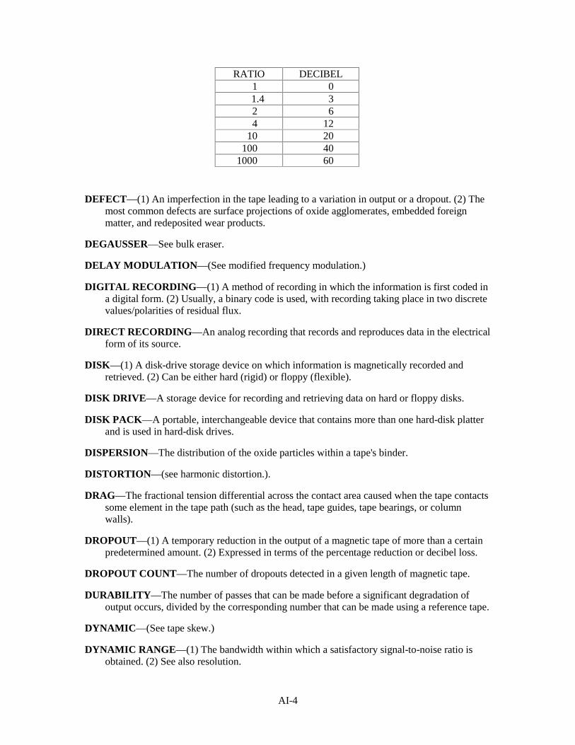
AI-4
RATIO DECIBEL1 0
1.4 32 64 12
10 20100 40
1000 60
DEFECT—(1) An imperfection in the tape leading to a variation in output or a dropout. (2) Themost common defects are surface projections of oxide agglomerates, embedded foreignmatter, and redeposited wear products.
DEGAUSSER—See bulk eraser.
DELAY MODULATION—(See modified frequency modulation.)
DIGITAL RECORDING—(1) A method of recording in which the information is first coded ina digital form. (2) Usually, a binary code is used, with recording taking place in two discretevalues/polarities of residual flux.
DIRECT RECORDING—An analog recording that records and reproduces data in the electricalform of its source.
DISK—(1) A disk-drive storage device on which information is magnetically recorded andretrieved. (2) Can be either hard (rigid) or floppy (flexible).
DISK DRIVE—A storage device for recording and retrieving data on hard or floppy disks.
DISK PACK—A portable, interchangeable device that contains more than one hard-disk platterand is used in hard-disk drives.
DISPERSION—The distribution of the oxide particles within a tape's binder.
DISTORTION—(see harmonic distortion.).
DRAG—The fractional tension differential across the contact area caused when the tape contactssome element in the tape path (such as the head, tape guides, tape bearings, or columnwalls).
DROPOUT—(1) A temporary reduction in the output of a magnetic tape of more than a certainpredetermined amount. (2) Expressed in terms of the percentage reduction or decibel loss.
DROPOUT COUNT—The number of dropouts detected in a given length of magnetic tape.
DURABILITY—The number of passes that can be made before a significant degradation ofoutput occurs, divided by the corresponding number that can be made using a reference tape.
DYNAMIC—(See tape skew.)
DYNAMIC RANGE—(1) The bandwidth within which a satisfactory signal-to-noise ratio isobtained. (2) See also resolution.
AI-5
DYNAMIC SKEW—The change in skew caused by tape motion.
DYNAMIC TAPE SKEW—(See tape skew.)
EQUIPMENT NOISE—(See noise.)
ERASURE—A process by which a signal recorded on a tape is removed and the tape made readyfor rerecording. May be accomplished in two ways. (1) In ac erasure, the tape isdemagnetized by an alternating magnetic field that is reduced in amplitude from an initiallyhigh value. May be accomplished by passing the tape over an erase head fed with high-frequency ac, or by placing the whole roll of tape in a decreasing ac field (bulk erasure).(2) In dc erasure, the tape is saturated by applying a primarily unidirectional field. May beaccomplished by passing the tape over a head fed with dc or over a permanent magnet.Additional stages may be included in dc erasure to leave the tape in a more nearlyunmagnetized condition.
FERRITE—A powdered and compressed ferric-oxide material that has both magnetic propertiesand light resistance to current flow.
FLOPPY DISK—(See disk.)
FLUTTER—(See wow.)
FLUX—A term, with reference to electrical or electromagnetic devices, that designatescollectively all the electric or magnetic lines of force in a region.
FLUX DENSITY—The number of magnetic lines of force passing through a given area.
FM—(See frequency modulation.)
FREQUENCY MODULATION (FM)—(1) A flux reversal at the beginning of a cell timerepresents a clock bit. (2) A "1" bit is a flux reversal at the center of the cell time. (3) A "0"bit is an absence of a flux reversal.
FREQUENCY RESPONSE—(1) The variation of sensitivity with signal frequency. (2) Thefrequency response of a tape is usually given in decibels relative to a referenced frequency-output level. (3) Also called amplitude/frequency response.
GAMMA-FERRIC OXIDE—The common magnetic constituent of magnetic tapes in adispersion of fine, needle-like particles within the coating.
GAP EROSION—(1) The read or write gap increased in length and retreated below the headsurface. (2) Usually due to deterioration of core material at the edges of the gap.
GAP LOSS—(1) The loss in output due to the finite gap length of the reproduce head. (2) Theloss increases as the wavelength decreases.
GAP WIDTH—The dimension of the gap of a magnetic head measured in the directionperpendicular to the direction of the tape path.
GAUSS—The metric unit of the magnetic flux density equal to 1 Mx/CM 2.
HARD DISK—(See disk.)
AI-6
HARD FERRITE—A ferrite with a very low wear rate when compared with the soft metallaminations.
HARD METAL LAMINATIONS—(See core material, hard.)
HARD SOLID METAL—(see core material, hard.)
HARMONIC DISTORTION—A signal non-linearity with harmonics of the fundamental in theoutput when the input signal is sinusoidal.
HEAD CONTAMINATION—(See tape-to-head separation.)
HEAD CONTOUR—(1) The complex shape of the contacting surface of a head as a result ofmanufacture, head lapping, or wear. (2) The contour of a head is always changingthroughout the head's life and, in many cases, is responsible for retiring the head.
HEAD CRASH—A term used for the damage to a hard disk caused by the physical contact madebetween the magnetic read/write heads and the surface of the hard-disk platter.
HEAD STICK—(1) A common word for a large increase in head-to-tape friction caused by (a) astick by-product exuded by conditions due to tape age, temperature/humidity, and head-to-tape pressure, and (b) very smooth tapes coupled with large area heads. (2) See also sticktionand stick-slip.
HEAD-TO-TAPE CONTACT—The degree that a tape's magnetic coating approaches thesurface of the record or reproduce head during normal operation.
INTERLAYER TRANSFER—Any loose material, such as oxide, generated by tape wear or ahead-stick condition which is transferred from the oxide to the back of the tape, or from theback side to the oxide when the tape is wound on a reel.
INTERMODULATION DISTORTION—(1) A signal non-linearity with frequencies in theoutput equal to sums and differences of integral multiples of the component frequenciespresent in the input signal. (2) Harmonies are usually not included as part of theintermodulation distortion.
INTERSYMBOL INTERFERENCE—(1) An interference resulting in a phase shift of the cellplayback crossover point with respect to the data clock. (2) When a recording system haslimited record resolution, a flux transition being recorded will extend beyond its cellboundaries, adding or subtracting from the flux in the adjacent bit cells of symbols.
IRON OXIDE—(See gamma-ferric oxide.)
LAMINATIONS—(see core material.)
LATERAL DIRECTION—The direction across the width of the tape.
LAYER-TO-LAYER ADHESION—The tendency for adjacent layers of tape in a roll to adhereto one another.
LAYER-TO-LAYER TRANSFER—The magnetization of a layer of tape in a roll by the fieldfrom a nearby recorded layer, sometimes referred to as print through.
LBE—(See lower band edge.)
AI-7
LINEARITY—The extent to which the magnitude of the reproduced output is directlyproportional to the magnitude of the signal applied to the input of the recorder.
LONG-TERM TAPE SPEED—(See tape speed.)
LONGITUDINAL CURVATURE—Any deviation from the straightness of a length of tape.
LOOSE DEBRIS—Any material that is very lightly bonded to the tape or the head's top surface,removable by tape motion.
LOWER BAND EDGE (LBE)—The lower band edge of the recorder/reproducer response(usually at the −3-dB point).
LUBRICANT—(See additive.)
MAGNETIC INSTABILITY—(1) The property of a magnetic material that causes variations inthe residual flux density of a tape to occur with temperature, time, and/or mechanicalflexing. (2) A function of particle size, magnetizing field strength, and anisotropy.
MAGNETIC MEDIA—A base film, coated with magnetic particles held in a binder. (Themagnetic particles are usually needle-like, single-domain, gamma-ferric oxide.)
MAGNETIZING FIELD STRENGTH—The instantaneous strength of the magnetic fieldapplied to a sample of magnetic material.
MFM—(See modified frequency modulation.)
MODIFIED FREQUENCY MODULATION (MFM)—(1) A code that has a "1" and a "O"corresponding to the respective presence or absence of a transition in the center of thecorresponding bit cell. (2) Additional transitions at the cell boundaries occur only betweenbit cells that contain consecutive "0" values. (3) Also called delay modulation.
MODULATION NOISE—(See noise.)
NOISE—Any unwanted electrical disturbances other than crosstalk or distortion components thatoccur at the output of the reproduce amplifier. (1) System noise is the total noise producedby the whole recording system, including the tape. (2) Equipment noise is produced by allthe components of the system, with the exception of the tape. (3) Tape noise can bespecifically ascribed to the tape. The following are typical sources of tape noise: (a) Bulk-erased noise arises when a bulk-erased tape with the erase and record heads completelydeenergized is reproduced. (b) Zero-modulation noise arises when an erased tape with theerase and record heads energized as they would be in normal operation, but with zero inputsignal, is reproduced. This noise is usually 3 to 4 dB higher than the bulk-erased noise. Thedifference between bulk-erased and zero-modulation noise is sometimes termed bias-inducednoise. (c) Saturation noise arises when a uniformly saturated tape is reproduced. This is oftensome 15 dB higher than the bulk-erased noise and is associated with imperfect particledispersion. (d) Dc noise arises when a tape that has been non-uniformly magnetized byenergizing the record head with dc, either in the presence or the absence of bias, isreproduced. This noise has pronounced, long, wavelength components that can be as muchas 20 dB higher than those obtained from a bulk-erased tape. At very high values of dc, thedc noise approaches the saturation noise. Dc noise is actually the low-frequency componentof modulation noise. (e) Modulation noise is essentially a modulation of the desired signalby noise that is caused by non-uniform dispersion of elementary magnetic particles in the
AI-8
tape’s coating material. This noise, which occurs only when a recorded tape is reproduced,increases with the intensity of the reproduced signal. Dc noise is actually the low-frequencycomponent of modulation noise.
NOISE PULSE—(1) A short-duration false signal occurring during the reproduction of a tape.(2) A signal that is of a magnitude considerably in excess of the average peak value of theordinary system noise.
NOMINAL BIT TIME—(1) The average bit time of recording at continuous maximum-fluxreversals. (2) Also called cell time.
NON-RETURN-TO-ZERO (NRZ0)—The flux reversal for a "0"; no flux reversal for a "1."
NON-RETURN-TO-ZERO INVERTED (NRZI)—The flux reversal for a "1"; no flux reversalfor a "0."
NON-RETURN-TO-ZERO (NRZ) RECORDING—(See digital recording.)
OERSTED—A unit of magnetic field strength.
OUTPUT—The magnitude of the reproduced signal voltage, usually measured at the output ofthe reproduced amplifier.
OXIDE BUILD-UP—The accumulation of oxide or wear products as deposits on the surface ofheads and guides.
OXIDE LOADING—(1) A measure of the density with which oxide is packed into a coating.(2) The weight of the oxide per unit volume of the coating.
OXIDE SHED—The loosening of particles of oxide from the tape coating during use.
PACKING DENSITY—The amount of digital information recorded along the length of a tape,measured in bits per inch.
PARTICLE ORIENTATION—The rotation of needle-like particles so that their longestdimensions tend to lie parallel to one another.
PARTICLE SHAPE—The needle-like particles of gamma-ferric oxide used in conventionalmagnetic tape, with a dimensional ratio of about 6 to 1.
PARTICLE SIZE—The physical dimensions of magnetic particles used in a magnetic tape.
PERMANENT ELONGATION—The percentage of elongation remaining on a tape or a lengthof base film after a given load applied for a given time has been removed.
PLASTICIZER—(See additive.)
POLYESER—(1) An acronym for polyethylene glycol terephthalate. (2) The material mostcommonly used as a base film for precision magnetic tape.
READ/WRITE ERASE HEAD—A three-gap head (read, write, erase) on one body. Sometimesthe erase head is bolted to the read/write head.
READ/WRITE HEAD—A two-gap head (read, write) on one body.
AI-9
REEL—The metal-, glass-, or plastic-flanged hub on which magnetic tape is wound.
REFERENCE TAPE—A tape used as a reference against which the performances of other tapesare compared.
REMANENCE—(1) The magnetic flux density that remains in a magnetic circuit after removalof applied magnetomotive force. (2) Is not necessarily equal to residual flux density.
REMOVABLE FIXED DISK—A hard-disk device (usually) with only one hard-disk platterthat's used to record and retrieve data.
RESISTIVITY—(See coating resistance.)
RESOLUTION (DYNAMIC RANGE)—The average peak-to-peak signal amplitude at themaximum flux reversal divided by the average peak-to-peak signal amplitude at theminimum flux reversal at the desired recording method.
RETENTIVITY—The maximum value of residual flux density corresponding to saturation fluxdensity.
RZ RECORDING—(See digital recording.)
SATURATION FLUX DENSITY—(1) The maximum intrinsic flux density possible in asample of magnetic material. (2) The intrinsic flux density asymptotically approaches thesaturation flux density as the magnetizing field strength increases.
SATURATION NOISE—(See noise.)
SCRATCH—A long, narrow, straight defect in the top surface of a head track or a tape.
SENSITIVITY—The magnitude of the output when reproducing a tape recorded with a signal ofgiven magnitude and frequency.
SEPARATION LOSS—The loss in output that occurs when the surface of the coating of amagnetic tape fails to make perfect contact with the surface of the record or reproduce head.
SHEDDING—The loss of oxide or other particles from the coating or backing of a tape, usuallycausing contamination of the tape transport and, by redeposit, of the tape itself.
SHORT-TERM TAPE SPEED—(See tape speed.)
SIGNAL-TO-NOISE RATIO—(1) The ratio of the power output of a given signal to the noisepower in a given bandwidth. (2) Is usually measured by the corresponding root mean squaresignal and noise voltages appearing across a constant output resistance.
SKEW—A deviation of a line connecting the average displacement of the read or write trackgaps from a line perpendicular to the reference edge of the tape in the direction of tapemotion.
SKEW TAPE—(1) The continuous strings of "1" values written on a properly adjusted tapedrive for the entire recoverable length of the tape. (2) An "all '1' pattern" on all tracks.(3) The write head, the write delays, and the tape drive adjusted to write with minimumphysical skew and gap scatter.
AI-10
SOFT METAL LAMINATIONS—(See core material, soft.)
SPOKING—A buckling in which the tape pack is deformed into a shape that approximates apolygon.
SPOOL—(See reel.)
SQUEAL—(See stick-slip.)
STANDARD REFERENCE TAPE—A tape intended for daily calibration, the performance ofwhich has been calibrated to the amplitude reference tape.
STATIC—(See tape skew.)
STICK-SLIP—(1) A low-speed phenomenon. (2) A relationship between tension, temperature,humidity, wrap angle, head material, tape binder, and elastic properties. (3) When detectedaudibly, it is a squeal.
STICKTION—The tape's adhering to transport components, such as heads or guides.
STIFFNESS—(1) The resistance to bending the tape. (2) A function of tape thickness. (3) Amodulus of elasticity.
SURFACE TREATMENT—Any process by which the surface smoothness of the tape coatingis improved after it has been applied to the base film.
SYSTEM NOISE—(See noise.)
TAPE CONTAMINATION—(See tape-to-head separation.)
TAPE NOISE—(See noise.)
TAPE PACK—The form taken by the tape wound on a reel.
TAPE SKEW—(1) The tape's deviation from following a linear path when transported across theheads. (2) The terms static and dynamic distinguish between the physically fixedcomponents and the fluctuating components of total tape skew.
TAPE SPEED—(1) The speed at which the tape is transported across the read/write head duringnormal recording or reproduction. (2) Long-term speed is averaged over a minimum of 15inches of tape (in inches per second). (3) Short-term speed is the instantaneous (dynamic)tape speed (in inches per second).
TAPE-TO-HEAD SEPARATION—(1) Separation.—The separation between a magnetic headand the magnetic tape caused by the (a) foil-bearing effect, (b) improper head contour, whichgenerates standing waves in the tape, and (c) surface roughness of the tape. These conditionsare interrelated and are greatly influenced by tape tension and tape compliancy. In a properlydesigned system, tape roughness is the limit of head-to-tape separation, usually <10 fm.(2) Changes.—(a) Head contamination is the debris attached to the head, which causes thetape to lift away from the head, forming a tent-like deformation of the tape. This tent doesnot move or change shape until the contamination is removed. (b) Tape contaminationincludes particles attached to the tape, resulting in a tent that moves across the head with thetape. (3) Effective.—(a) The actual distance from the magnetic storage material on the tapeto the top of the active magnetic core material at the read or write gape. (b) The effective
AI-11
head-to-tape separation is usually somewhat larger than the mechanical head-to-tapeseparation.
TAPE TRANSPORT—(1) The mechanism that extracts magnetic tape from a storage device,moves it across magnetic heads at a controlled speed and then feeds it into another storagedevice. (2) Typical storage devices are tape loops, bins, reels, cassettes, and cartridges.(3) The tape transport is the part of a magnetic tape recorder/reproducer system thatnormally consists of magnetic heads, magnetic tape, transport, record electronics, andreproduce electronics.
TEAR STRENGTH—The force required to initiate and/or propagate a tear in a specially shapedspecimen of tape or base film.
TOTAL THICKNESS—The sum of the thicknesses of the base film and the magnetic coating,as well as back coating, when applied. The total thickness governs the length of tape that canbe wound on a given reel.
TRACK—An area of the tape's surface that coincides with the location of the recordedmagnetization produced by one record gap.
TRACK WIDTH—The width of the track corresponding to a given record gap.
UBE—(See upper band edge.)
UNDERCUT—(See washout.)
UNIFORMITY—The extent to which the output remains free from variations in amplitude.Uniformity is usually specified as the positive and negative deviations from the averageoutput within a roll of tape.
UPPER BAND EDGE (UBE)—The upper band edge of the recorder/reproducer response(usually at the −3dB point).
VOID—An area where material is missing on the surface of a tape or on a head's track.
WASHOUT—(1) A hard-coated head whose magnetic core material has a much higher wear ratethan the coating. (2) The radius of curvature of the core material will be larger than thesurrounding coating of the softer material, which could even be undercut, possibly causingan increase in the head-to-tape separation. (3) Also called undercut.
WAVELENGTH—The distance along the length of a sinusoidally recorded tape correspondingto one cycle.
WAVINESS—(1) A non-flat head's top surface perpendicular to the tape motion due to differentwear rates in top surface materials. The harder material will be up. The head core is usuallythe harder material; therefore, there will be increased head-to-tape contact pressure at thecost of tape life. (2) Can occur during break-in or field use.
WEAR ABILITY—(See durability.)
WEAR PRODUCT—Any material that is detached from the tape during use.
WEAR TEST—(See durability.)
AI-12
WIND—The way in which tape is wound onto a reel. An A-wind is one in which the tape iswound so that the coated surface faces toward the hub.
WINDER/CLEANER—A device that winds and cleans magnetic tape to restore it to a near-newcondition, providing the tape has not been physically damaged.
WOW AND FLUTTER—(1) The changes in signal-output frequency caused by tape-speedvariations occurring at relatively low and relative high rates, respectively. (2) Wow is nolonger used, but is incorporated into the flutter measurement.
WRITE FEEDTHROUGH—(1) The magnetic coupling from the write track to a read track inthe read/write head. (2) Also called crossfeed and crosstalk.
ZERO-MODULATION NOISE—(See noise.)
AII-1
APPENDIX II
REFERENCES
Magnetic Tape Recording Technical Fundamentals, Datatape Incorporated, 360 Sierra Madre Villa,Pasedena, CA, 1986.
Parallel Mode High Density Digital Recording Technical Fundamentals, Datatape Incorporated, 360Sierra Madre Villa, Pasedena, CA, 1976.
Aviation ASW Technician 3&2, NAVEDTRA 10353-D, Naval Education and Training ProfessionalDevelopment and Technology Center, Pensacola, FL, 1987.
Haynes, N. M., Transistor Circuits for Magnetic Recording, Howard W. Sams & Co., Indianapolis, IN,January 1964.
Magnetic Tape Recording for the Eighties, NASA Reference Publication 1075, Goddard Space FlightCenter, Green Belt, MD, 1982.
Data Systems Technician 3&2, Vol. 2, NAVEDTRA 10231, Naval Education and Training ProfessionalDevelopment and Technology Center, Pensacola, FL, 1987.
AN/TNH-21 Recorder-Reproducer Set, Sound, Instruction Manual, National Security Agency, Fort G.Meade, MA, December 1973.
NSA Technical Support Manual, Magnetic Tape Recording, National Security Agency, Washington DC,1957.
System Description Manual for Recorder-Reproducer Set, Signal Data, AN/USH-23(V), NAVELEX0967-LP-546-1010, Naval Electronics Systems Command, Washington, DC, 1975.
Operation and Maintenance Instructions for Model 100X Magnetic Tape Recorder, NAVELEX 0967-LP-551-3010, Naval Electronics Systems Command, Washington, DC, 1976.
Recorder-Reproducer Set, Magnetic Disk AN/UYH-3(V), Operation and Maintenance Instructions,NAVSEA SE600-AA-MMM-010/AN/UYH-3(V), Naval Sea Systems Command, Washington, DC,1982.
Input/Output Interfaces, Standard Digital Data, Navy Systems, MIL-STD-1397A(NAVY), Naval SeaSystems Command, Washington, DC, 1983.
Technical Manual, Operation Instructions, Maintenance Instructions, Parts List, Installation Instructions,Recorder-Reproducer Set, Signal Data, USH-26(V), NAVSEA SE640-AF-MMO-010/USH-26(V),Naval Sea Systems Command, Washington, DC, 1981.
Operating Instructions and Organizational Maintenance Instructions, Chap. 1, Signal Data Recorder-Reproducer Set, AN/USH-24(V), 521600 and 521600-0001, SPAWAR 0967-LP-590-0010, Spaceand Naval Warfare Systems Command, Washington, DC, 1979.
Data Processing Technician Third Class, NAVEDTRA 10263, Naval Education and TrainingProfessional Development and Technology Center, Pensacola, FL, 1987.

INDEX-1
MODULE 23 INDEX A Access time, magnetic disk recording, 8-20 Actuator arm assembly, 8-13 to 8-15
floppy disk drive transports, 8-12 hard disk drive transports, 8-14
Analog magnetic recording tape, 2-2 Automatic tape degausser, 2-11 B Bi-phase level encoding, 7-7 C Capstan speed control, 4-11
capstan motor drive circuit, 4-13 capstan speed monitor, 4-12 comparison network, 4-13 precision frequency source, 4-11 speed correction circuit, 4-13 speed select network, 4-12
Cleaning magnetic tape recorder heads, 3-5 Closed-loop capstan drive, 4-8 to 4-10
differential velocity capstans, 4-9 dual-motors dual capstan, 4-9 peripheral drive capstans, 4-10
Co-axial tape reeling configuration, 4-6 to 4-7 Computer-compatible digital tape recorders,
7-7 Construction of magnetic tape recorder heads,
3-2 to 3-4 Control electronics, magnetic disk drive, 8-17 Co-planar tape reeling configuration, 4-6 D Definitions, digital magnetic tape recording,
7-3 Degaussers, magnetic tape, 2-11
automatic tape degausser, 2-11 manual tape degausser, 2-11
Degaussing magnetic tape, 2-10 to 2-12 Demagnetizing magnetic tape recorder heads,
3-5 to 3-7
Demagnetizing magnetic tape recorder transports, 4-14
Differential velocity capstans, 4-9 Digital data, recording, 8-10 to 8-12
frequency modulation (FM) encoding, 8-10 to 8-11
modified frequency-modulation (MFM) encoding, 8-10
run-length-limited (RLL) encoding, 8-12 Digital magnetic recording tape, 2-2 to 2-3 Digital magnetic tape recording, 7-1 to 7-8
computer-compatible digital tape recorders, 7-7
definitions, 7-3 encoding methods, 7-4 to 7-7 formats, 7-1 to 7-3 instrumentation magnetic tape recorders,
7-8 introduction to, 7-1 parallel digital magnetic tape recording
format, 7-2 serial digital magnetic tape recording
format, 7-2 serial-parallel digital magnetic tape
recording format, 7-3 telemetry digital tape recorders, 7-7
Direct record electronics, 5-1 to 5-2 Direct reproduce electronics, 5-2 to 5-3 Diskettes, flexible magnetic recording, 8-2 to
8-5 Disks, fixed magnetic recording, 8-6 to 8-9 Drive electronics circuit board, 8-13
floppy disk drive transports, 8-12 to 8-13 hard disk drive transports, 8-14 to 8-15
Drive motor/spindle assembly, 8-13 floppy disk drive transports, 8-12 hard disk drive transports, 8-14
Dropout errors, magnetic tape, 2-3 Dual-motors dual capstan, 4-9 to 4-10 E Electronics, 5-1 to 5-5, 8-17 to 8-18
direct record, 5-1 to 5-2
INDEX-2
Electronics—Continued direct reproduce, 5-2 to 5-3 frequency modulation (FM) record, 5-3
to 5-4 frequency modulation (FM) reproduce,
5-4 to 5-5 magnetic disk drive, control electronics,
8-17 magnetic disk drive, interface electronics,
8-18 to 8-20 magnetic disk drive, write/read
electronics, 8-18 Encoding methods, digital magnetic tape
recording, 7-4 to 7-7 bi-phase level encoding, 7-7 Non-Return-to-Zero (NRZ) encoding, 7-6 return-to-Bias (RB) encoding, 7-4 return-to-Zero (RZ) encoding, 7-5
Encoding methods, frequency modulation (FM), 8-10 to 8-11
Encoding methods, modified frequency-modulation (MFM), 8-11
Encoding methods, run-length-limited (RLL), 8-12
Enhanced Non-Return-to-Zero-Level (E-NRZ-L) encoding, 7-6
Enhanced small device interface (ESDI), 8-19 Erase heads, 3-4 Erasing, floppy disk, 8-5 Erasing, hard disk, 8-9 to 8-10 Erasing magnetic tape, 2-10 to 2-11 F Fixed magnetic recording disks, 8-6
hard disk construction, 8-6 hard disk data organization, 8-7 hard disk erasing, 8-9 to 8-10 hard disk handling, storage, and shipping,
8-8 to 8-9 Flexible magnetic recording diskettes, 8-2 to
8-5 Floppy disk construction, 8-2 to 8-4 Floppy disk data organization, 8-3 to 8-4 Floppy disk drive preventive maintenance,
8-16 Floppy disk drive transports, 8-12 to 8-13
Floppy disk drive transports—Continued actuator arm assembly, 8-13 drive electronics circuit board, 8-13 drive motor/spindle assembly, 8-13 head arm assembly, 8-13
Floppy disk erasing, 8-5 Floppy disk handling, storage, and shipping,
8-4 to 8-5 Flutter, 6-8 to 6-10 Formats, digital magnetic tape recording, 7-1
to 7-3 Frequency modulation (FM) encoding, 8-10
to 8-11 Frequency modulation (FM) record
electronics, 5-3 to 5-4 Frequency modulation (FM) reproduce
electronics, 5-4 to 5-5 Frequency response, 6-3 to 6-5 H Hard disk construction, 8-6 Hard disk drive preventive maintenance, 8-17 Hard disk drive transports, 8-14 to 8-15
actuator arm assembly, 8-15 drive electronics circuit board, 8-15 drive motor/spindle assembly, 8-14 head arm assembly, 8-15
Hard disk erasing, 8-9 to 8-10 Hard disk handling, storage, and shipping, 8-8
to 8-9 Harmonic distortion, 6-5 Head arm assembly, floppy disk drive
transports, 8-13 Head arm assembly, hard disk drive
transports, 8-15 Head-to-tape sticking, 2-5 Heads, erase, magnetic tape recorder, 3-4 Heads, magnetic tape recorder, 3-1 to 3-9 I Instrumentation magnetic tape recorders, 7-8 Integrated drive electronics (IDE), 8-20 Interface electronics, magnetic disk drive,
8-18 to 8-20
INDEX-3
Interface electronics, magnetic disk drive—Continued
enhanced small device interface (ESDI), 8-19
integrated drive electronics (IDE), 8-20 Naval tactical data system (NTDS)
interface, 8-18 small computer systems interface (SCSI),
8-19 ST-506/412 interface, 8-18 to 8-19
Interleave factor, magnetic disk recording, 8-20 to 8-21
L Latency period, magnetic disk recording, 8-20 Layer-to-layer adhesion, 2-5 Level errors, magnetic tape, 2-4 M Magnetic disk drive electronics, 8-17 to 8-20 Magnetic disk drive transports, 8-12 to 8-15
floppy disk drive transports, 8-12 to 8-13 hard disk drive transports, 8-14 to 8-15
Magnetic disk recording, 8-1 to 8-25 fixed magnetic recording disks, 8-6 to
8-9 flexible magnetic recording diskettes, 8-2
to 8-5 recording digital data, 8-10 to 8-12 run length-limited (RLL) encoding, 8-12 specifications, 8-20 to 8-21
Magnetic heads, 1-5 Magnetic recorders, history of, 1-2 to 1-4
input signal, 1-5 magnetic heads, 1-5 prerequisites for, 1-5 to 1-6 recording medium, 1-5
Magnetic tape, 2-1 to 2-15 analog, 2-2 base material, 2-2 causes of failure, 2-4 to 2-8 digital, 2-2 dropout errors, 2-3 erasing and degaussing, 2-10 to 2-12 glue, 2-2
Magnetic tape—Continued handling, 2-12 to 2-13 level errors, 2-4 noise errors, 2-3 oxide coating, 2-2 packaging for shipping, 2-14 skew errors, 2-3 to 2-4 storing, 2-13 tape reels and tape cartridges, 2-9 to 2-10
Magnetic tape failure, causes of, 2-4 accidental damage, 2-5 causes of, layer-to-layer adhesion, 2-5 cinching, 2-6 to 2-7 dirt build-up, 2-6 environmental damage, 2-5 to 2-6 excessive tape and head wear, 2-6 head-to-tape sticking, 2-5 normal wear, 2-4 oxide shedding, 2-5 pack slip, 2-7 spoking, 2-8 tape deformation, 2-5 winding errors, 2-6 to 2-9 windowing, 2-8
Magnetic tape recorder heads, 3-1 to 3-9 cleaning, 3-5 construction of, 3-2 to 3-4 demagnetizing, 3-5 erase heads, 3-4 record and reproduce heads, 3-3 to 3-4
Magnetic tape recorder record and reproduce electronics, 5-1 to 5-6
direct record electronics, 5-1 to 5-2 direct reproduce electronics, 5-2 to 5-3 FM record electronics, 5-3 to 5-4 FM reproduce electronics, 5-4 to 5-5
Magnetic tape recorder transports, 4-1 to 4-16 capstan speed control, 4-11 to 4-13 cleaning, 4-13 to 4-14 closed-loop capstan drive, 4-8 to 4-10 demagnetizing, 4-14 to 4-15 open-loop capstan drive, 4-7 to 4-8 tape reeling systems, 4-2 to 4-7 tape transport configurations, 4-7 to 4-10
Magnetic tape recording specifications, 6-1 to 6-14
INDEX-4
Magnetic tape recording specifications—Continued
flutter, 6-9 to 6-10 frequency response, 6-3 to 6-5 harmonic distortion, 6-5 to 6-7 phase response, 6-7 to 6-9 signal-to-noise ratio, 6-2 to 6-3 skew, 6-11 to 6-13 time-base error, 6-10 to 6-11
Maintenance, floppy disk drive, 8-16 Maintenance, hard disk drive, 8-17 Manual tape degausser, 2-11 to 2-12 Modified frequency-modulation (MFM)
encoding, 8-11 N Naval Tactical Data System (NTDS)
interface, 8-18 Noise errors, magnetic tape, 2-3 Non-Return-to-Zero (NRZ) encoding, 7-5 Non-Return-to-Zero-Level (NRZ-L)
encoding, 7-6 Non-Return-to-Zero-Mark (NRZ-M)
encoding, 7-6 to 7-7 Non-Return-to-Zero-Space (NRZ-S)
encoding, 7-7 O Open-loop capstan drive, 4-7 to 4-8 Oxide shedding, 2-5 P Packaging magnetic tape for shipping, 2-14 Parallel digital magnetic tape recording
format, 7-2 Peripheral drive capstans, 4-10 Phase response, 6-7 to 6-9 Physical properties of magnetic tape, 2-1 to
2-2 base material, 2-2 glue, 2-2 oxide coating, 2-2
Precision frequency source, 4-11
R Record and reproduce heads, 3-3 Recording density, magnetic disk recording,
8-21 Recording medium, 1-5 References, AII-1 to AII-2 Return-to-Bias (RB) encoding, 7-4 Return-to-Zero (RZ) encoding, 7-4 Run-length-limited (RLL) encoding, 8-12 S Seek time, magnetic disk recording, 8-20 Serial digital magnetic tape recording format,
7-2 Serial-parallel digital magnetic tape recording
format, 7-3 Signal-to-noise ratio, 6-2 to 6-3 Skew, 6-11 to 6-13 Skew errors, magnetic tape, 2-3 to 2-4 Small computer systems interface (SCSI),
8-19 Speed correction circuit, 4-13 Speed select network, 4-12 ST-506/412 interface, 8-18 to 8-19 Storing magnetic tape, 2-13 T Take-up control reeling systems, 4-2 Tape buffering reeling systems, 4-3 to 4-4 Tape deformation, 2-5 Tape reeling systems, 4-2 to 4-7
configurations, 4-6 take-up control reeling systems, 4-2 tape buffering reeling systems, 4-3 to 4-4 tape guides, 4-4 to 4-5 two-motor reeling systems, 4-2
Tape reels and tape cartridges, 2-9 to 2-10 Tape transport configurations, 4-7 to 4-11
closed-loop capstan drive, 4-8 to 4-11 open-loop capstan drive, 4-7 to 4-8
Telemetry digital tape recorders, 7-7 Time-base error, 6-10 to 6-11

INDEX-5
Transfer rate, magnetic disk recording, 8-21 Transports, 8-12 to 8-15
magnetic disk drive, 8-12 to 8-13 Two-motor reeling systems, 4-2
W Write/read electronics, magnetic disk drive,
8-18


Assignment Questions
Information: The text pages that you are to study areprovided at the beginning of the assignment questions.

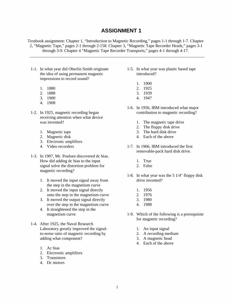
1
ASSIGNMENT 1
Textbook assignment: Chapter 1, “Introduction to Magnetic Recording,” pages 1-1 through 1-7. Chapter2, “Magnetic Tape,” pages 2-1 through 2-158. Chapter 3, “Magnetic Tape Recorder Heads,” pages 3-1
through 3-9. Chapter 4 “Magnetic Tape Recorder Transports,” pages 4-1 through 4-17.___________________________________________________________________________________
1-1. In what year did Oberlin Smith originatethe idea of using permanent magneticimpressions to record sound?
1. 18802. 18883. 19004. 1908
1-2. In 1925, magnetic recording beganreceiving attention when what devicewas invented?
1. Magnetic tape2. Magnetic disk3. Electronic amplifiers4. Video recorders
1-3. In 1907, Mr. Poulsen discovered dc bias.How did adding dc bias to the inputsignal solve the distortion problem formagnetic recording?
1. It moved the input signal away fromthe step in the magnetism curve
2. It moved the input signal directlyonto the step in the magnetism curve
3. It moved the output signal directlyover the step in the magnetism curve
4. It straightened the step in themagnetism curve
1-4. After 1925, the Naval ResearchLaboratory greatly improved the signal-to-noise ratio of magnetic recording byadding what component?
1. Ac bias2. Electronic amplifiers3. Transistors4. Dc motors
1-5. In what year was plastic based tapeintroduced?
1. 19002. 19253. 19394. 1947
1-6. In 1956, IBM introduced what majorcontribution to magnetic recording?
1. The magnetic tape drive2. The floppy disk drive3. The hard disk drive4. Each of the above
1-7. In 1966, IBM introduced the firstremovable-pack hard disk drive.
1. True2. False
1-8. In what year was the 5 1/4" floppy diskdrive invented?
1. 19562. 19763. 19804. 1988
1-9. Which of the following is a prerequisitefor magnetic recording?
1. An input signal2. A recording medium3. A magnetic head4. Each of the above
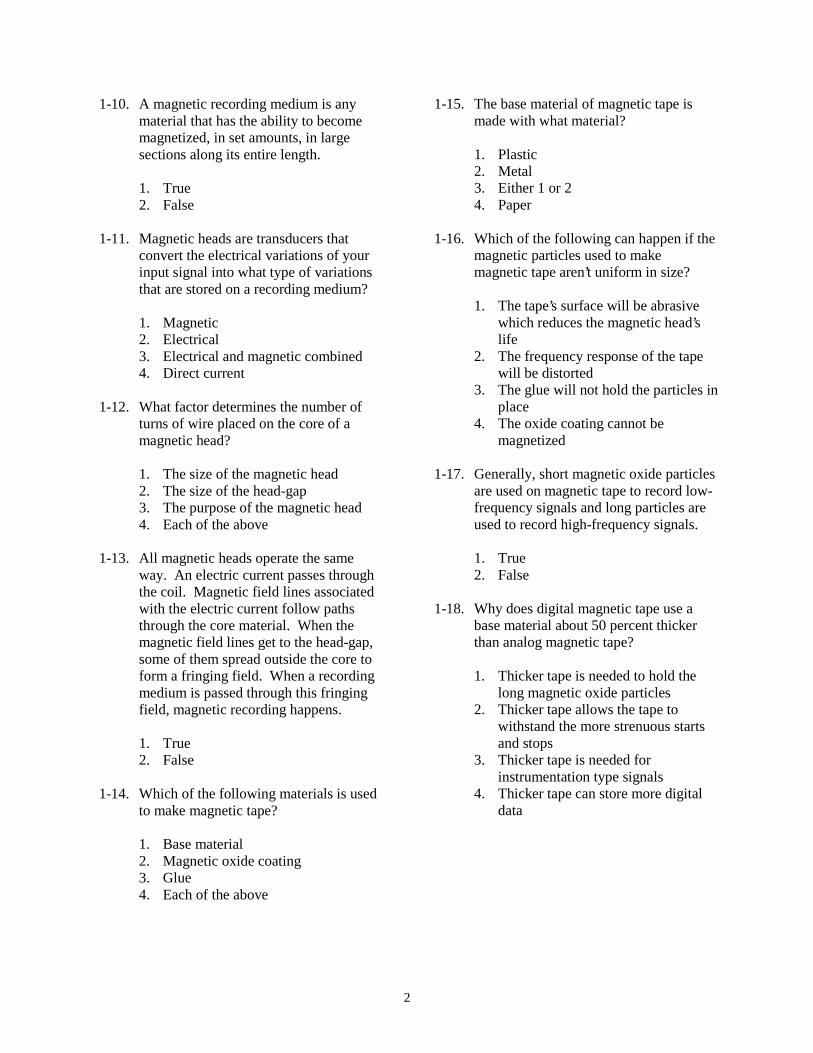
2
1-10. A magnetic recording medium is anymaterial that has the ability to becomemagnetized, in set amounts, in largesections along its entire length.
1. True2. False
1-11. Magnetic heads are transducers thatconvert the electrical variations of yourinput signal into what type of variationsthat are stored on a recording medium?
1. Magnetic2. Electrical3. Electrical and magnetic combined4. Direct current
1-12. What factor determines the number ofturns of wire placed on the core of amagnetic head?
1. The size of the magnetic head2. The size of the head-gap3. The purpose of the magnetic head4. Each of the above
1-13. All magnetic heads operate the sameway. An electric current passes throughthe coil. Magnetic field lines associatedwith the electric current follow pathsthrough the core material. When themagnetic field lines get to the head-gap,some of them spread outside the core toform a fringing field. When a recordingmedium is passed through this fringingfield, magnetic recording happens.
1. True2. False
1-14. Which of the following materials is usedto make magnetic tape?
1. Base material2. Magnetic oxide coating3. Glue4. Each of the above
1-15. The base material of magnetic tape ismade with what material?
1. Plastic2. Metal3. Either 1 or 24. Paper
1-16. Which of the following can happen if themagnetic particles used to makemagnetic tape aren’t uniform in size?
1. The tape’s surface will be abrasivewhich reduces the magnetic head’slife
2. The frequency response of the tapewill be distorted
3. The glue will not hold the particles inplace
4. The oxide coating cannot bemagnetized
1-17. Generally, short magnetic oxide particlesare used on magnetic tape to record low-frequency signals and long particles areused to record high-frequency signals.
1. True2. False
1-18. Why does digital magnetic tape use abase material about 50 percent thickerthan analog magnetic tape?
1. Thicker tape is needed to hold thelong magnetic oxide particles
2. Thicker tape allows the tape towithstand the more strenuous startsand stops
3. Thicker tape is needed forinstrumentation type signals
4. Thicker tape can store more digitaldata

3
1-19. There are four types of tape errors thatcan degrade the performance of amagnetic recording system. Which ofthe following tape errors is the mostcommon and causes a 50% or more dropin signal strength?
1. Noise2. Skew3. Signal dropout4. Level
1-20. Which of the following contaminants cancause signal dropouts?
1. Dust2. Lint3. Oil4. Each of the above
1-21. Which of the following items onmagnetic tape will cause noise errors?
1. Dust or lint2. A cut3. A scratch4. Both 2 and 3 above
1-22. Brand "X" magnetic tape is rated for 5volts (± 10%). Which of the followingminimum and maximum voltage levels iswhat the output signal level could varybefore it is considered a level error?
1. 4.95/5.052. 4.75/5.253. 4.5/5.54. 4/6
1-23. Magnetic tape can eventually becomeunusable when it comes in contact withthe fixed surfaces of a recorder over longperiods of time. What causes this type oftape failure?
1. Environmental damage2. Normal wear3. Winding errors4. Accidental damage
1-24. Ideally, magnetic tape should be usedand stored within what temperature andhumidity range?
1. 40 - 80º F, 60 - 80% humidity2. 50 - 70º F, 60 - 80% humidity3. 60 - 80º F, 60 - 80% humidity4. 60 - 80º F, 40 - 60% humidity
1-25. Using magnetic tape in a workplace thatexceeds the ideal temperature andhumidity ranges can cause which of thefollowing types of environmentaldamage to the tape?
1. Dirt build-up2. Layer-to-layer sticking3. Tape deformation4. Each of the above
1-26. At temperatures above 130 degrees, whathappens to a tape's oxide coating?
1. Becomes soft2. Separates from the base material3. Both 1 and 2 above4. Becomes brittle
1-27. What causes head-to-tape sticking?
1. Temperatures below 2º F2. Dirty record/reproduce heads3. The tape binder glue softens4. Static electricity
1-28. Which of the following environmentalconditions could create static electricitywhich attracts dirt build-up on the tapeand tape recorder parts?
1. Relative humidity of 5%2. Temperature of 28º F3. Relative humidity of 96%4. Temperature of 135º F

4
1-29. Excessive tape and head wear caused byincreased friction as the tape passes overthe heads can happen if the relativehumidity is more that what maximumpercent?
1. 70%2. 85%3. 95%4. 90%
1-30. Winding errors can happen whenimproper winding practices create anexcessive or uneven force as the tape isbeing wound onto a tape reel.
1. True2. False
1-31. When winding a tape onto a reel, younotice that a sudden stop causes the outerlayers of the tape to continue to spin afterthe inner layers have stopped. What typeof deformed tape pack does this cause?
1. Pack-slip2. Cinching3. Spoking4. Windowing
1-32. The magnetic tape on your reel isunwinding unevenly and rubbing againstthe sides of the reel and the recorder’stape guides. What type of deformed tapepack could cause this condition?
1. Spoking2. Windowing3. Pack-slip4. Skewing
1-33. You notice a spoked tape pack on thetake-up reel of your recorder. Whatcauses a spoked tape pack?
1. Tape is wound over a small particleon the reel hub
2. A distorted reel hub creates unevenpressures as the tape is wound ontothe reel
3. Tape is wound with increasingtension toward the end of thewinding
4. Each of the above
1-34. Which of the following tape packdeformities is an example of windowing?
1. The inner part of the tape pack isbuckled and deformed
2. The tape pack contains steps causedby the tape shifting from side to sideduring winding
3. The tape pack contains voids or see-through air gaps
4. Each of the above
1-35. Which of the following materials can beused to make tape reels?
1. Plastic2. Metal3. Glass4. Each of the above
1-36. The flanges of a magnetic tape reel aredesigned to guide the magnetic tape ontothe reel.
1. True2. False
1-37. Magnetic tape is erased by exposing it towhat type of magnetic field?
1. A gradually decreasing dc field2. A gradually increasing dc field3. A gradually decreasing ac field4. A gradually increasing ac field
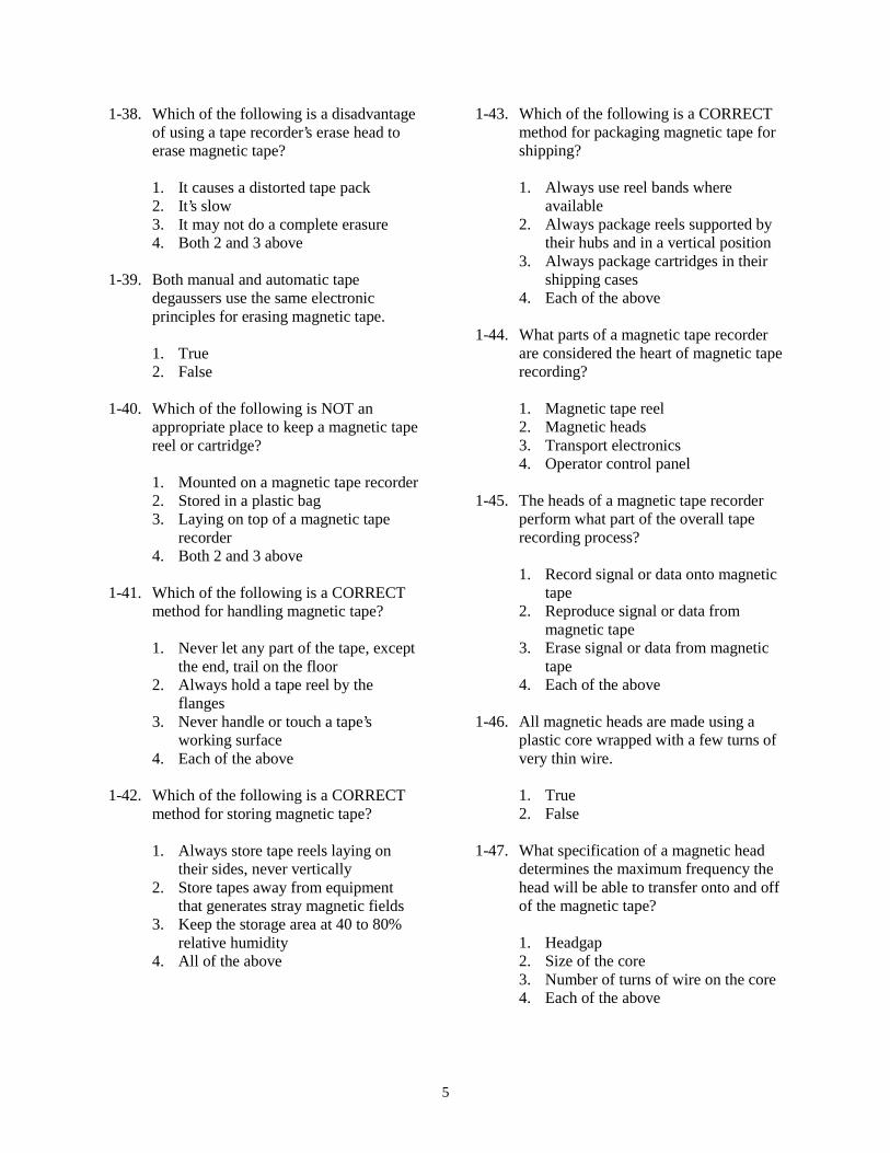
5
1-38. Which of the following is a disadvantageof using a tape recorder’s erase head toerase magnetic tape?
1. It causes a distorted tape pack2. It’s slow3. It may not do a complete erasure4. Both 2 and 3 above
1-39. Both manual and automatic tapedegaussers use the same electronicprinciples for erasing magnetic tape.
1. True2. False
1-40. Which of the following is NOT anappropriate place to keep a magnetic tapereel or cartridge?
1. Mounted on a magnetic tape recorder2. Stored in a plastic bag3. Laying on top of a magnetic tape
recorder4. Both 2 and 3 above
1-41. Which of the following is a CORRECTmethod for handling magnetic tape?
1. Never let any part of the tape, exceptthe end, trail on the floor
2. Always hold a tape reel by theflanges
3. Never handle or touch a tape’sworking surface
4. Each of the above
1-42. Which of the following is a CORRECTmethod for storing magnetic tape?
1. Always store tape reels laying ontheir sides, never vertically
2. Store tapes away from equipmentthat generates stray magnetic fields
3. Keep the storage area at 40 to 80%relative humidity
4. All of the above
1-43. Which of the following is a CORRECTmethod for packaging magnetic tape forshipping?
1. Always use reel bands whereavailable
2. Always package reels supported bytheir hubs and in a vertical position
3. Always package cartridges in theirshipping cases
4. Each of the above
1-44. What parts of a magnetic tape recorderare considered the heart of magnetic taperecording?
1. Magnetic tape reel2. Magnetic heads3. Transport electronics4. Operator control panel
1-45. The heads of a magnetic tape recorderperform what part of the overall taperecording process?
1. Record signal or data onto magnetictape
2. Reproduce signal or data frommagnetic tape
3. Erase signal or data from magnetictape
4. Each of the above
1-46. All magnetic heads are made using aplastic core wrapped with a few turns ofvery thin wire.
1. True2. False
1-47. What specification of a magnetic headdetermines the maximum frequency thehead will be able to transfer onto and offof the magnetic tape?
1. Headgap2. Size of the core3. Number of turns of wire on the core4. Each of the above
6
1-48. What is the only physical differencebetween a record head and a reproducehead?
1. Number of turns of wire on the core2. Size of the core material3. Type of core material used4. Each of the above
1-49. A certain magnetic recorder has amaximum recording frequency responseof 500 kHz. Which of the followingfrequencies would be a good frequencyto use as an erase signal?
1. 500 kHz2. 1200 kHz3. 1900 kHz4. Either 2 or 3
1-50. If you do NOT regularly clean arecorder’s magnetic heads, what is theprobable consequence?
1. Dirt, dust, lint, etc. will collect on theheads
2. Signal dropout errors will occur3. Both 1 and 2 above4. The tape pack will become skewed
1-51. What materials should you use to cleanmagnetic heads?
1. A bristled brush and non-detergentcleaner
2. A cotton-tipped applicator soaked inisopropyl alcohol
3. A cotton-tipped applicator soaked ina magnetic head cleanerrecommended by the manufacturer
4. Either 2 or 3 above
1-52. Magnetic heads can become magnetizedfrom many sources. Which of thefollowing sources, if any, couldmagnetize a magnetic head?
1. Stray magnetic fields2. Excessive humidity3. Poor quality magnetic tape4. None of the above
1-53. Magnetic head degaussers generate astrong ac magnetic field that dc-magnetizes the metal parts of a magnetichead.
1. True2. False
1-54. Which of the following is NOT aprocedure for demagnetizing magneticheads?
1. Remove the tape reel or cartridgefrom the recorder
2. Touch the energized degausser to thehead
3. Move the degausser back and forthacross the head for 15 to 30 seconds
4. De-energize the degausser when it’san arms length away
1-55. Which of the following is a function ofmagnetic tape transports?
1. Moves the magnetic tape across themagnetic heads
2. Holds the moving tape3. Protects the moving tape4. Each of the above
_______________________________________
IN ANSWERING QUESTIONS 1-56THROUGH 1-59, SELECT THEDESCRIPTION IN COLUMN B THAT BESTDESCRIBES THE MAGNETIC TAPERECORDER TRANSPORT PART LISTED INCOLUMN A.
1-56. Tape reelingsystem
1-57. Tape speedcontrolsystem
1-58. Electronicsub-system
1-59. Basicenclosure
1. Monitors and controlsthe movement ofmagnetic tape
2. Holds and protects thereels or cartridges ofmagnetic tape
3. Activates the reelingdevice to move themagnetic tape
4. Physically moves themagnetic tape acrossthe magnetic heads
_______________________________________

7
1-60. What type of tape reeling system uses a"free-spooling" supply reel and amotorized take-up reel?
1. Take-up control2. Two-motor reeling3. Tape buffering4. Both 2 and 3 above
1-61. What type of tape reeling system wasinvented to overcome the problems ofuneven tape tension and stretched tape?
1. Take-up control2. Two-motor reeling3. Tape buffering4. Both 2 and 3 above
1-62. Magnetic tape reeling systems that usethe spring tension method of tapebuffering use what type of device tosense changes in tape tension?
1. Vacuum air column2. Electro-mechanical3. Photo-sensitive4. Variable-static-sensor
1-63. What are the two types of tape guidesused on magnetic tape reeling systems?
1. Variable and stable2. Round and square3. Single and dual4. Fixed and rotary
1-64. A co-axial tape reeling configurationplaces the supply and take-up reels sideby side.
1. True2. False
1-65. In which of the following types of tapetransport capstan drive configurations isthe tape tension and head-to-tape contactmost likely to vary?
1. Dual-motor dual capstan drive2. Peripheral drive capstan3. Open-loop capstan drive4. Closed-loop capstan drive
1-66. Which of the following closed-loopcapstan drive tape transports will NOTwork in reverse?
1. Differential velocity capstan2. Peripheral drive capstan3. Both 1 and 2 above4. Dual-motors dual capstan
1-67. What type of capstan drive tape transportmoves the magnetic tape by placing thecapstan directly against the tape reel ortape pack?
1. Open-loop capstan drive2. Peripheral drive capstan3. Dual-motors dual capstan4. Differential velocity capstan
1-68. Capstan speed control is a very importantfunction of the magnetic tape transportsystem. Which of the following is NOTone of the six parts of a capstan speedcontrol?
1. Capstan speed monitor2. Speed select network3. Comparison network4. Reel motor drive circuit
1-69. What part of the capstan speed controlfunction normally uses a photo-opticaltachometer attached to the shaft of thecapstan motor?
1. Precision frequency source2. Speed select circuit3. Capstan speed monitor4. Comparison network
8
1-70. On some recorders, a servo control fromtape signal is supplied to the comparisonnetwork of the capstan speed controlfunction. What is the purpose of thissignal?
1. Speeds up or slows down the capstanmotor
2. Compensates for capstan speeddifferences when a recorded tape isplayed back on a different recorder
3. Monitors the true capstan motorspeed
4. Provides a reference frequency thatthe speed select network uses todrive the capstan motor
1-71. Which of the following items can be usedto clean most magnetic tape transports?
1. Isopropyl alcohol2. Cotton swabs3. Lint-free cloths4. Each of the above
1-72. Which of the following is NOT a correctprocedure for cleaning a magnetic tapetransport?
1. When available, always use cottonswabs vice lint-free cloths
2. Apply the cleaner onto the cottonswab or lint-free cloth
3. Clean the flanged parts of the tapeguides
4. While cleaning, switch swabs andcloths often
1-73. Magnetic tape transports should bedemagnetized periodically. To do this,use a hand-held degausser and follow theprocedures for demagnetizing magneticheads.
1. True2. False

9
ASSIGNMENT 2
Textbook assignment: Chapter 5, “Magnetic Tape Recorder Record and Reproduce Electronics,” pages5-1 through 5-6. Chapter 6, “Magnetic Tape Recording Specifications,” pages 6-1 through 6-15.
Chapter 7, “Digital Magnetic Tape Recording,” pages 7-1 through 7-9. Chapter 8 “ Magnetic DiskRecording,” pages 8-1 through 8-25.
___________________________________________________________________________________
2-1. Magnetic tape recorders use what type ofelectronic circuits to record andreproduce analog input signals?
1. Continuous wave2. Frequency modulation3. Amplitude modulation4. Both 2 and 3 above
2-2. Direct record electronics record inputsignals onto magnetic tape just as theyappeared at the recorder's input.
1. True2. False
2-3. Which part of the direct recordelectronics component takes the inputsignal and the bias signal and mixes themtogether?
1. Input pre-amplifier circuit2. Bias source3. Summing network4. Head driver circuit
2-4. Which part of the direct recordelectronics amplifies the signal from thesumming network and sends it to therecord head?
1. Bias source circuit2. Head driver circuit3. Input pre-amplifier circuit4. Low-pass filter circuit
2-5. The pre-amplifier circuit of the directreproduce electronics does which of thefollowing functions?
1. Amplifies the reproduced signal2. Removes the bias signal3. Both 1 and 2 above4. Corrects phase errors
2-6. What circuit in the direct reproduceelectronics takes the pre-amplified signaland fixes frequency response problemsthe reproduce magnetic head may havecaused?
1. Equalization and phase correctioncircuit
2. Output amplifier circuit3. Head driver circuit4. Summing network
2-7. What circuit of the direct reproduceelectronics serves as an impedancematcher?
1. Pre-amplifier circuit2. Output amplifier circuit3. Equalization and phase correction
circuit4. Head driver circuit
10
2-8. How do FM record electronics processthe incoming signal before sending it tothe record head?
1. A high frequency, negative bias isadded to the input signal
2. A summing network mixes the biasand input signal
3. Both 1 and 2 above4. The input signal is frequency
modulated onto the carrier frequencyof a record oscillator
2-9. In the FM record electronics, what is theoutput of the record oscillator circuit?
1. The demodulated input signal2. The frequency modulated carrier
signal3. A clean input signal with the
negative bias removed4. A combined input signal and
equalization signal
THIS SPACE LEFT BLANKINTENTIONALLY.
_______________________________________
IN ANSWERING QUESTIONS 2-10THROUGH 2-13, SELECT THEDESCRIPTION IN COLUMN B THAT BESTDESCRIBES THE PART OF FMREPRODUCE ELECTRONICS LISTED INCOLUMN A.
2-10. Pre-amplifiercircuit
2-11. Limiter/demodulatorcircuit
2-12. Low-passfilter circuit
2-13. Outputamplifier
1. Takes the signalfrom the limiter/demodulator andcleans-up any noiseor left over carriersignal
2. Takes the outputfrom the low-passfilter and amplifies itfor output
3. Takes the reproducesignal from themagnetic head andamplifies it
4. Stabilizes theamplitude level anddemodulates thesignal intelligencefrom the carriersignal
_______________________________________
2-14. Which of the following generates thenoise part of a recorder’s SNR?
1. Magnetic heads2. Magnetic tape3. Both 1 and 2 above4. Nearby equipment
2-15. The SNR can be stated in three differentways. Which of the following is NOTone of these ways?
1. Mean signal to RMS noise2. Peak-to-peak signal to RMS noise3. RMS signal to RMS noise4. Peak signal-to-RMS noise
11
2-16. Which of the following data should beincluded with all SNR specifications?
1. Record level2. Reproduce level3. Bandwidth4. Tape speed
2-17. What is the magnetic tape recordingspecification which gives a recorder’samplitude variation with frequency overa specified bandwidth?
1. Record level2. Frequency response3. Bandwidth4. Both 2 and 3 above
2-18. Your LPO tells you to test the frequencyresponse of a particular magnetic taperecorder. You use a signal generator tosweep through the frequencies as youmonitor the recorder’s output amplitudeon a VTVM. Which of the followingreadings in output amplitude wouldindicate the upper and lower end of therecorders bandwidth?
1. +/− 2-dB2. +/− 3-dB3. +/− 5-dB4. +/− 10-dB
2-19. Which of the following factors can limitor degrade the frequency response of amagnetic tape recorder?
1. The record head2. The reproduce head3. Magnetic head-to-tape contact4. Each of the above
2-20. If the frequencies of the harmonicdistortion are 2, 4, and 6 times the centerfrequency, what type of harmonicdistortion is this?
1. Linear2. Spatial3. Even-order4. Center frequency
2-21. Which of the following is a cause ofeven-order harmonics during magnetictape recording?
1. Defective magnetic tape2. Frequency response too low3. Permanently magnetized heads4. Each of the above
2-22. If you increase a magnetic tape recorder’ssignal bias level, what happens to theharmonic distortion?
1. Increases2. Remains the same3. Decreases4. Increases odd-order harmonic
distortion
2-23. When measuring the amount of harmonicdistortion in a magnetic tape recorder,what electronic test equipment shouldyou use?
1. Wave analyzer2. VTVM3. Spectrum analyzer4. All of the above
2-24. When measuring harmonic distortion,you set the signal generator to input a 12-kHz test signal. At the recorder’s output,what will be the frequency of the third-order harmonic?
1. 33-kHz2. 18-kHz3. 38-kHz4. 36 kHz
12
2-25. What magnetic tape recorderspecification expresses the variation ofthe phase shift with respect to frequency?
1. Frequency response2. Phase response3. Wow and Flutter4. Each of the above
2-26. Which of the following conditionsindicates that a magnetic tape recorderhas a good phase response specification?
1. The SNR and frequency response arewithin tolerance
2. The wave analyzer shows a perfectsine wave
3. The recorder reproduces anundistorted square wave
4. Each of the above
2-27. What magnetic tape recorderspecification expresses the result of non-uniform tape motion caused by variationsin tape speed that produces frequencymodulation of signals recorded ontomagnetic tape?
1. Frequency response2. Phase response3. Flutter4. Time-base error
2-28. Which of the following magnetic taperecorder transport parts can cause highfrequency flutter (above 1000 Hz)?
1. Magnetic heads2. Rotating tape guides3. Fixed tape guides4. Both 1 and 3 above
2-29. A magnetic tape recorder’s flutterspecification is usually expressed as apercent of peak or as a peak-to-peakvalue for what type of recorder?
1. Audio2. Instrumentation3. Video4. All of the above
2-30. The time-base error (TBE) magnetic taperecorder specification is closely related toflutter. Which of the followingstatements best reflects this relationship?
1. TBE is an inverse measure of theeffects of flutter on the stability ofrecorded data
2. TBE is a direct measure of theeffects of flutter on the frequencyresponse of recorded data
3. TBE is a direct measure of theeffects of flutter on the stability ofrecorded data.
4. TBE is a direct measure of theeffects of flutter on the bias level ofrecorded data.
2-31. The simplest way to measure a recorder’sTBE is with what test equipment?
1. VTVM2. Sweep analyzer3. Oscilloscope4. Ohmeter
2-32. There are two types of skew. What typedoes not show up when magnetic tapesare recorded and reproduced on the samemagnetic tape recorder?
1. Positive2. Dynamic3. Negative4. Fixed
2-33. Which of the following is NOT a causeof dynamic skew?
1. Gap scatter in the magnetic headstack
2. Sticking tape transport guides3. Warped magnetic tape4. Worn tape transport guides
13
2-34. Which of the following is NOT a formatfor digital magnetic tape recording?
1. Serial-parallel2. Bi-phase3. Serial4. Parallel
2-35. Which of the following digital magnetictape recording formats is normally usedfor instrumentation recording when theinput data rate is high?
1. Serial-Parallel2. Serial3. Both 1 and 2 above4. Bi-phase
2-36. The return-to-bias digital magnetic taperecording encoding method usesmagnetic tape that is normally in a"neutral" condition.
1. True2. False
2-37. Which of the following digital magnetictape encoding methods is the mostwidely used?
1. RB2. NRZ3. E-RZ4. RZ
2-38. Which of the four variations of NRZencoding works best in high densitymagnetic tape recording and offers a bit-error rate of one error per 1 million bits?
1. E-NRZ-L2. NRZ-L3. NRZ-M4. NRZ-S
2-39. Digital magnetic tape recorders are usedto store and retrieve which of thefollowing types of data?
1. Computer programs2. Radar and other pulsed type signals3. Special signals with a bandwidth of
less than 500 kHz4. Each of the above
2-40. Telemetry digital magnetic taperecorders are frequently called widebandrecorders.
1. True2. False
2-41. Floppy disks are made of round plasticdisks coated with magnetic oxideparticles and enclosed in a plastic jacket.
1. True2. False
2-42. When discussing floppy disks, what ismeant by the "density" of a floppy disk?
1. The thickness of the plastic disk2. How much the disk can store3. The thickness of floppy disk jacket4. The number of sectors on the disk
_______________________________________
IN ANSWERING QUESTIONS 2-43THROUGH 2-46, SELECT THE STORAGECAPACITY IN COLUMN B THAT BESTDESCRIBES THE TYPE OF FLOPPY DISKIN COLUMN A.
2-43. 5-1/4" doubledensity
2-44. 5-1/4" high density 2-45. 3-1/2" double
density 2-46. 3-1/2" high density
1. 1,200,000 bytes2. 720,000 bytes3. 360,000 bytes4. 1,400,000 bytes
_______________________________________
14
2-47. Data is stored on floppy disks in circular"tracks." Each track is then broken upinto arcs called "cylinders."
1. True2. False
2-48. When a floppy disk is sectored using thesoft sectoring method, the computersoftware determines the sector size andplacement. What is this process called?
1. Centering2. Addressing3. Formatting4. Rastering
2-49. When you handle, store, or ship floppydisks, which of the following statementsis NOT a precaution you should take?
1. Always store 8" and 5 1/4" floppydisks in their envelopes when not inuse
2. Always write on a floppy disk labelfirst, and then place it on the disk
3. Always lay floppy disks on their sidewhen storing them
4. Always ship floppy disks in theirappropriate shipping containers
2-50. Which of the following items cangenerate magnetic fields that can destroydata on a floppy disk?
1. Paper clip2. Telephone3. Printer4. Both 2 and 3 above
2-51. How can you erase a floppy disk?
1. Record over it2. Degauss it3. Reformat it4. Both 2 and 3 above
2-52. A computer places data on a hard disk byusing one of what two methods?
1. Cylinder or sector2. Cylinder or circular3. Sector or quadrant4. Sector or record
2-53. Using the sector method, a hard diskdrive locates a place on a hard disk withonly one platter by using three locationnumbers. Which of the following isNOT one of those location numbers?
1. Surface number2. Track number3. Cylinder number4. Sector number
2-54. When you handle, store, or shipremovable hard disks, which of thefollowing statements is NOT aprecaution you should take?
1. Don’t touch any exposed recordingsurfaces
2. Keep them away from food, liquids,and cigarette smoke
3. Store them in an environment thatstays between 32 to 95 degreesFahrenheit and 40 to 85% relativehumidity
4. Keep dirt, dust, etc., off of therecording surface by storing them intheir case when not in use
2-55. How can you declassify a removablehard disk which contains classifiedinformation?
1. Reformat it2. Degauss it3. Both 1 and 2 above4. Destroy it using the procedures in
OPNAVINST 5510.1
15
2-56. Which of the following encodingmethods is NOT used for encodingdigital data onto magnetic disks?
1. Sector encoding2. Run length limited3. Modified frequency modulation4. Frequency modulation
_______________________________________
IN ANSWERING QUESTIONS 2-57THROUGH 2-60, SELECT THEDESCRIPTION IN COLUMN B THATDESCRIBES THE FLOPPY DISK DRIVEPART LISTED IN COLUMN A.
2-57. Head armassembly
2-58. Driveelectronicscircuit board
2-59. Drivemotor/spindleassembly
2-60. Actuator armassembly
1. Holds and spins thefloppy disk
2. Holds the magneticread/write heads
3. Controls theelectromechanical-high density parts
4. Positions the headsover the disks
_______________________________________
2-61. What part of a hard disk drive transportuses either a dc stepper motor or a voicecoil to position the heads for writing datato the correct track of the disk pack?
1. Drive motor/spindle assembly2. Head arm assembly3. Actuator arm assembly4. Drive electronics circuit board
2-62. What part of a hard disk drive transportholds the four magnetic heads, and isattached to the transport’s actuator armassembly?
1. Cylinder assembly2. Head arm assembly3. Sectoring assembly4. Drive motor/spindle assembly
2-63. Why do floppy disk drives require morepreventive maintenance than hard diskdrives?
1. They are not sealed units2. Oxide coating from disks sticks to
transport parts3. Both 1 and 2 above4. The drive circuit board is less
protected
2-64. Which of the following is a mainfunction of the control electronics part ofa disk drive’s electronics component?
1. Take incoming data from theinterface electronics
2. Spin the disk at the proper speed3. Move the heads across the recording
surface4. Both 2 and 3 above
2-65. Which of the following is a function ofthe interface electronics part of a diskdrive’s electronics component?
1. Convert data from the host computerfrom serial to parallel, and viceversa, as needed
2. Receive write/read control signalsfrom the host computer
3. Receive control signals to format adisk from the host computer
4. All of the above
2-66. Which of the following is NOT one ofthe five most common disk driveinterfaces in use today?
1. Drive motor/spindle interface2. Naval tactical data system interface3. ST-506/412 interface4. Enhanced small device interface
16
2-67. What type of disk drive interface is oftenused in the hard disk drives installed inolder IBM-compatible desktopcomputers that have a maximum capacityof 125MB?
1. Drive motor/spindle interface2. Enhanced small device interface3. ST-506/412 interface4. Integrated drive electronics
2-68. What type of disk drive interface uses ahigh-level interface which requires only alogical sector number to locate thedesired data on a disk?
1. Enhanced small device interface2. Integrated drive electronics3. Drive motor/spindle interface4. Small computer systems interface
2-69. What type of disk drive interfaceincludes all of the controller cardelectronics in the hard disk drive andoffers a transfer rate of up to 1 MB?
1. Small computer systems interface2. Integrated drive electronics3. Naval tactical data system4. Enhanced small device interface
2-70. Which of the following is NOT a benefitof the SCSI disk drive interface overprevious interfaces?
1. Can handle disk drives of almost anysize
2. Disconnects itself from the hostcomputer’s bus while it processesrequests
3. Can transfer data up to 24 Mbits/sec4. Can daisy-chain up to eight units off
of one controller
_______________________________________
IN ANSWERING QUESTIONS 2-71THROUGH 2-74, SELECT THE MAGNETICDISK RECORDING SPECIFICATION INCOLUMN B THAT MATCHES THEDEFINITION IN COLUMN A.
2-71. Indicates number ofphysical sectors that arebetween logical sectorson a hard disk
2-72. Total time it takes a diskdrive to retrieve a sectorof data
2-73. Time it takes for amagnetic head to positionitself over a specific track
2-74. Time it takes a specificsector of a specific trackto position itself underthe magnetic head
1. Seek time2. Latency
period3. Access time4. Interleave
factor
_______________________________________
2-75. The speed at which a disk drive and adisk drive controller working togethercan transfer data to the host computer iswhat disk recording specification?
1. Seek time2. Transfer rate3. Access time4. Interleave factor