Embed Size (px)
Citation preview
Page 1 of 20
Navigator 2500 - 3000 upgrade to MKII
This is the description of how to upgrade Navigator 2500-3000 from MKI to MKII version.
Improvements after upgrade:Higher OCV > 90VStronger HF ignition in order to get reliable TIG starting when using argon mix gasses.
WARNINGQualified personnel ONLY may perform this upgrade.
Disconnect the machine from the wall plug before opening the machine.
Page 2 of 20
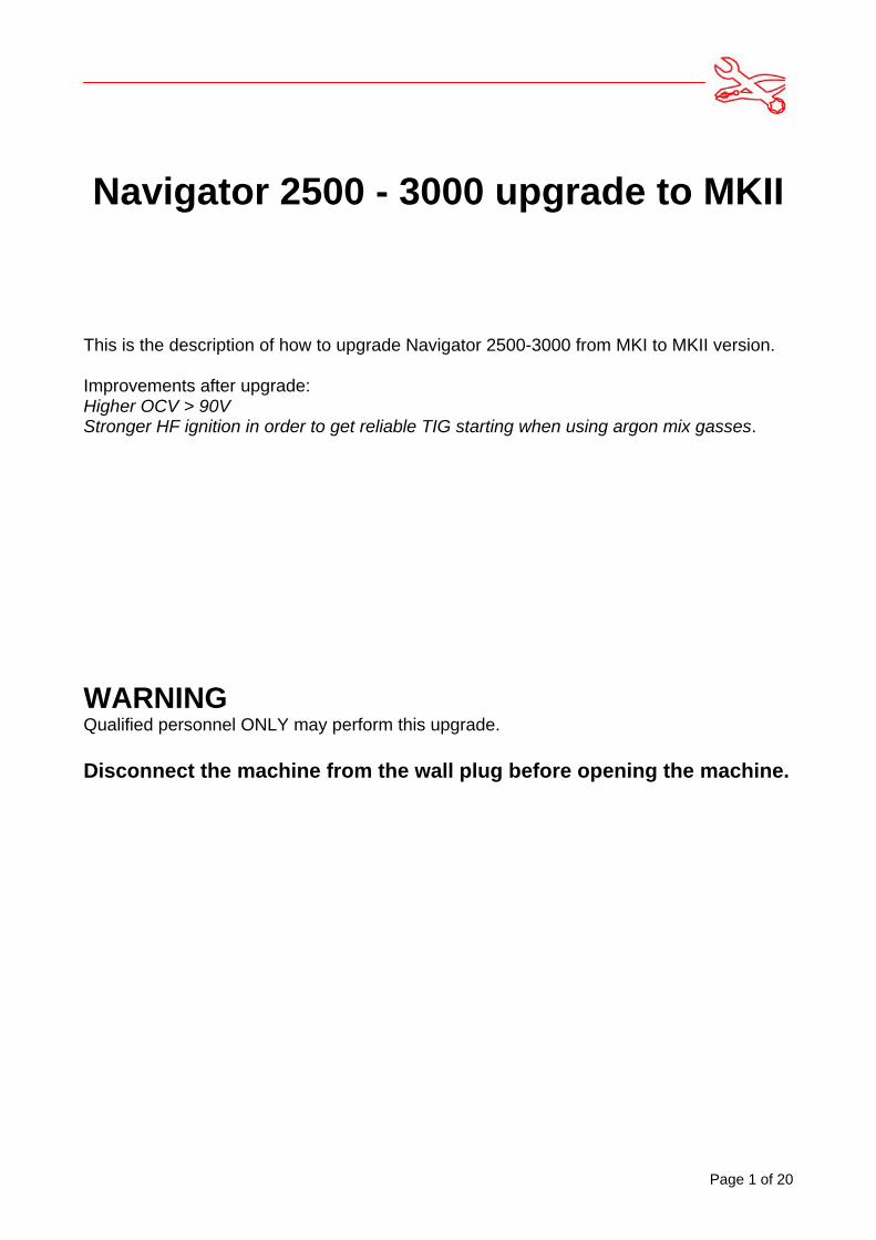
Take off both side panels and top panel.
1: Remove parts. The AUX transformer and some screws and bolts are reused, all otherparts are disposed.
PCB 71613433
AUX Transformer to reuse Filter PCB
HF choke, HF transformer, inductor, switch transformer
Remove the upper RCfilter on AC module
Disconnect redand gray wires

Page 3 of 20
2: Move wire in plug from pin 1 to pin 6.
Mover GRAY wire frompin 1 to pin 6
Page 4 of 20
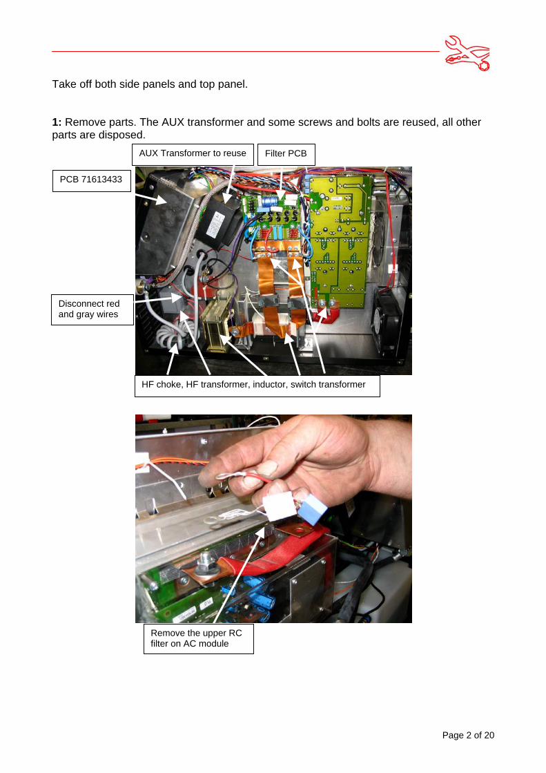
3: Remount the AUX transformer again in the machines right side. Use the original holesand screw
Page 5 of 20
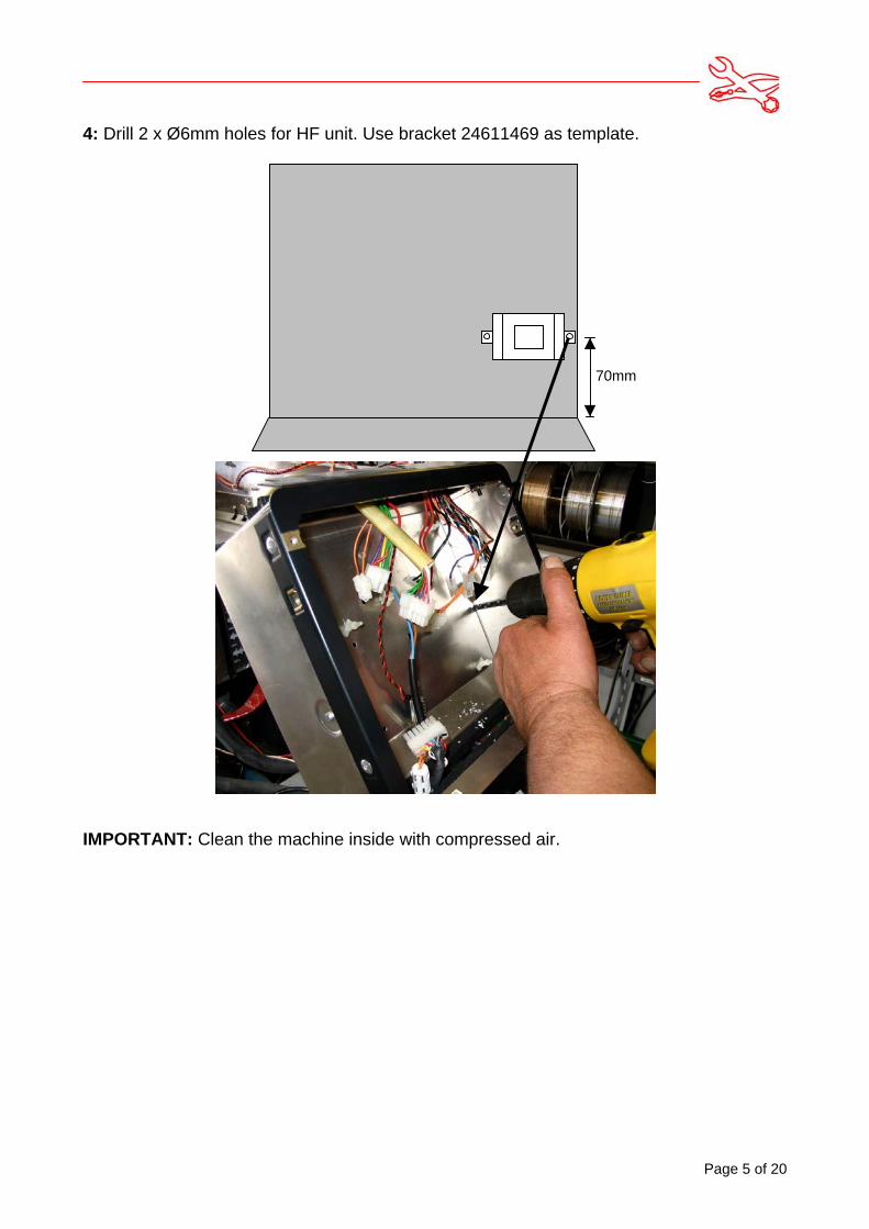
4: Drill 2 x Ø6mm holes for HF unit. Use bracket 24611469 as template.
IMPORTANT: Clean the machine inside with compressed air.
70mm
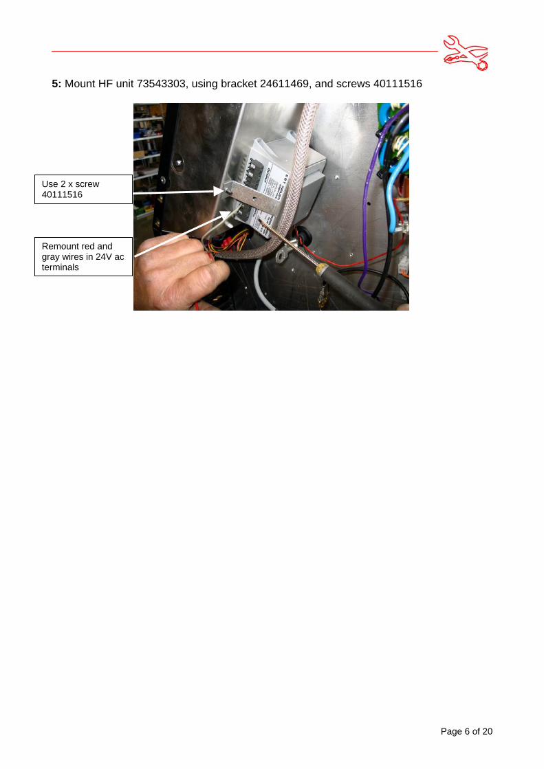
5: Mount HF unit 73543303, using bracket 24611469, and screws 40111516
Use 2 x screw40111516
Remount red andgray wires in 24V acterminals
Page 6 of 20
Page 7 of 20
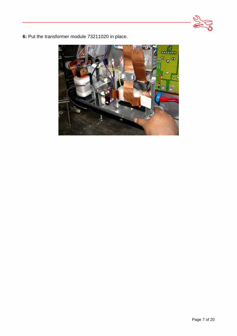
6: Put the transformer module 73211020 in place.
Page 8 of 20
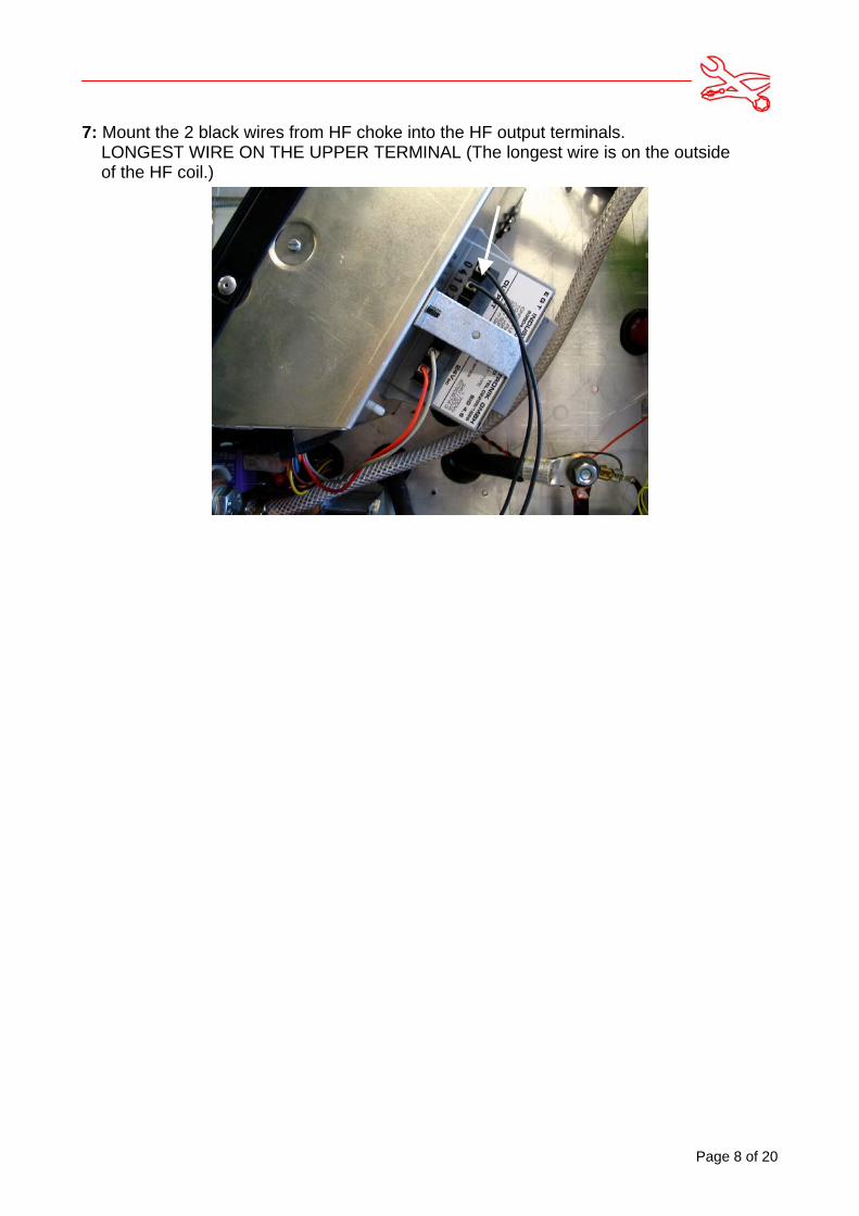
7: Mount the 2 black wires from HF choke into the HF output terminals. LONGEST WIRE ON THE UPPER TERMINAL (The longest wire is on the outside of the HF coil.)
Page 9 of 20
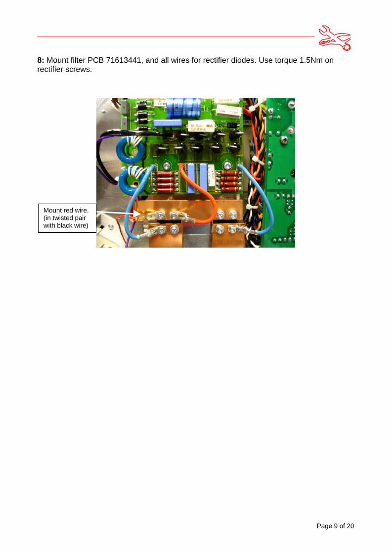
8: Mount filter PCB 71613441, and all wires for rectifier diodes. Use torque 1.5Nm onrectifier screws.
Mount red wire.(in twisted pairwith black wire)
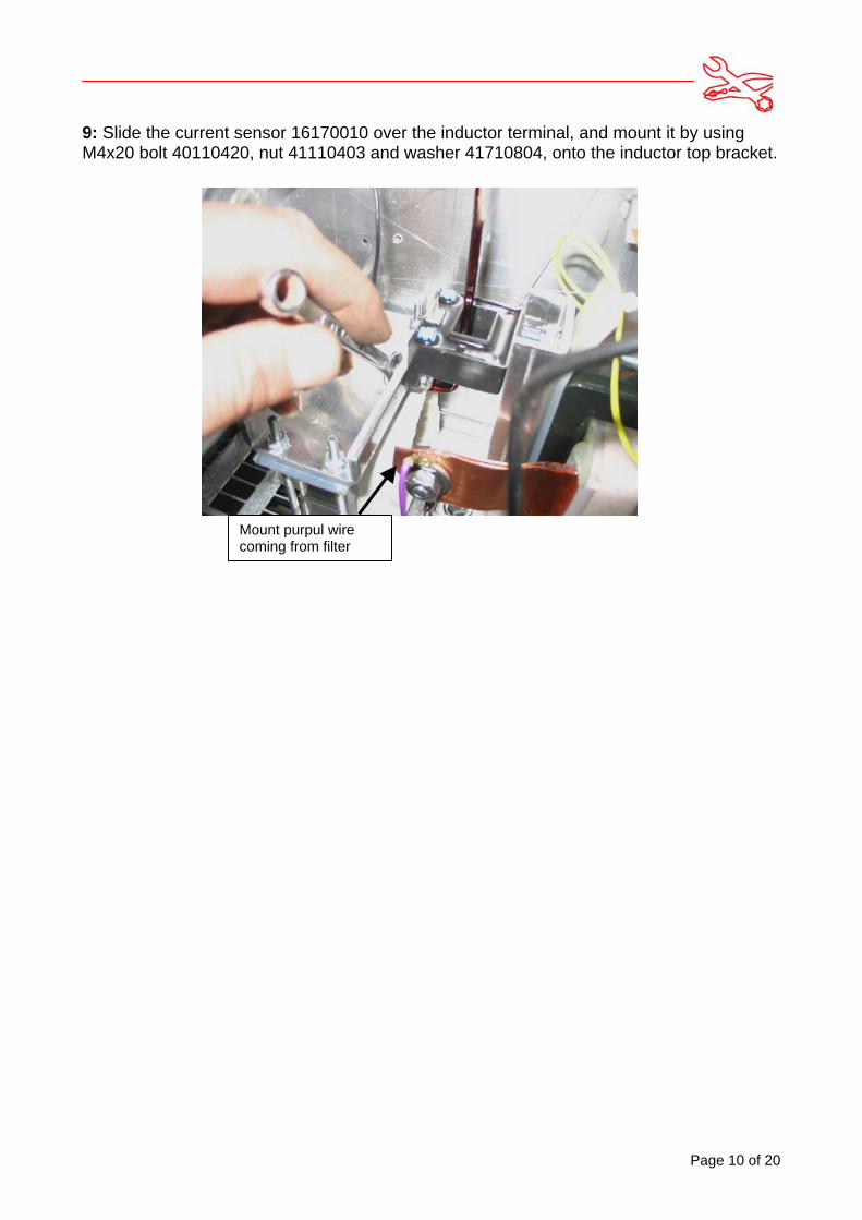
9: Slide the current sensor 16170010 over the inductor terminal, and mount it by usingM4x20 bolt 40110420, nut 41110403 and washer 41710804, onto the inductor top bracket.
Mount purpul wirecoming from filter
Page 10 of 20
Page 11 of 20
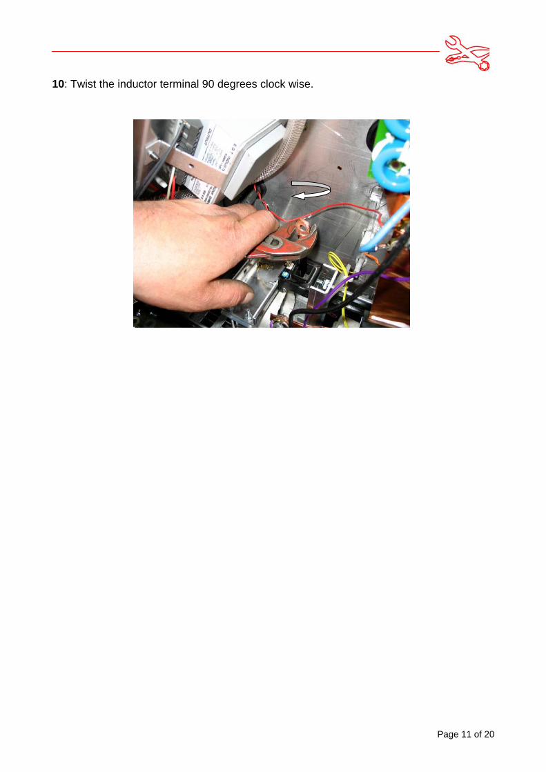
10: Twist the inductor terminal 90 degrees clock wise.
Page 12 of 20
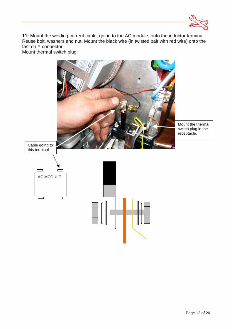
11: Mount the welding current cable, going to the AC module, onto the inductor terminal.Reuse bolt, washers and nut. Mount the black wire (in twisted pair with red wire) onto thefast on Y connector.Mount thermal switch plug.
Mount the thermalswitch plug in thereceptacle.
AC MODULE
Cable going tothis terminal
Page 13 of 20
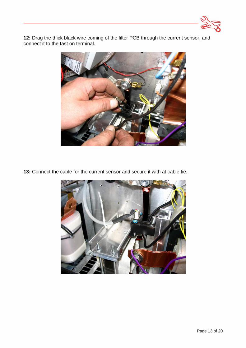
12: Drag the thick black wire coming of the filter PCB through the current sensor, andconnect it to the fast on terminal.
13: Connect the cable for the current sensor and secure it with at cable tie.
Page 14 of 20
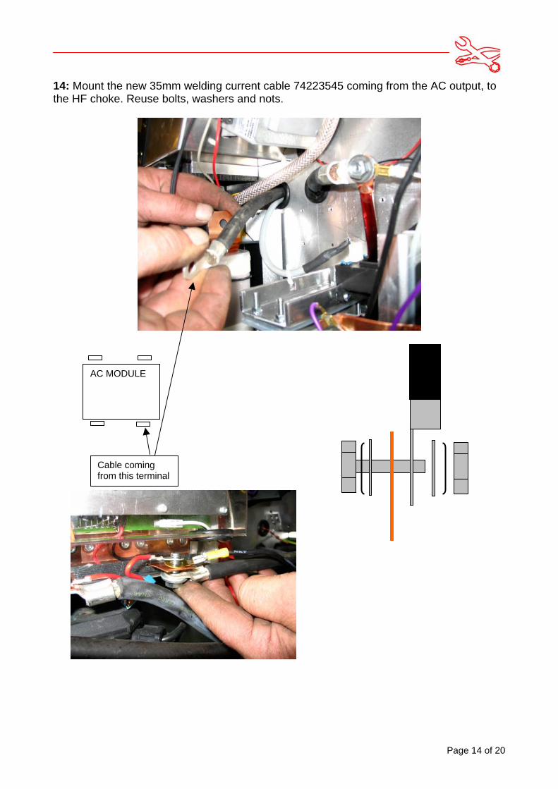
14: Mount the new 35mm welding current cable 74223545 coming from the AC output, tothe HF choke. Reuse bolts, washers and nots.
AC MODULE
Cable comingfrom this terminal

Page 15 of 20
15: Connect the last 2 transformer calbles to the switch PCB. Reuse bolts and washers.
Page 16 of 20
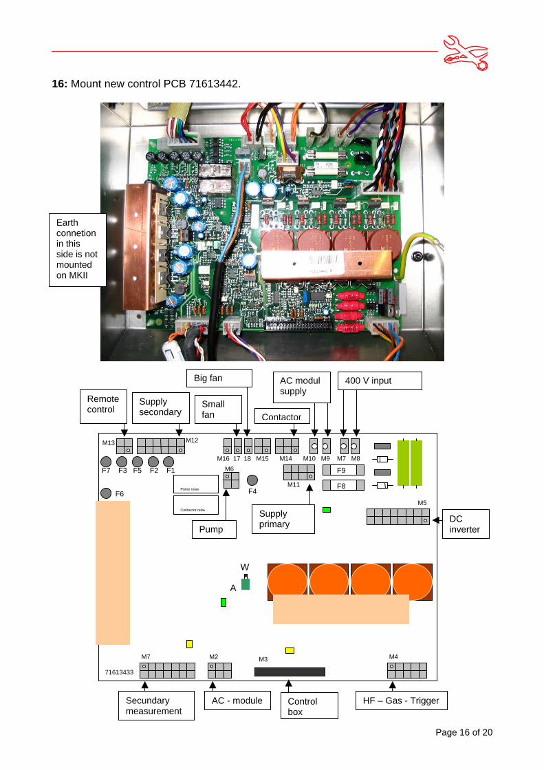
16: Mount new control PCB 71613442.
A
W
M13 M12
M16 17 18 M15 M14
M11
M10 M9 M7 M8
M5
M6
M7 M2 M4M3
71613433
AC - moduleSecundarymeasurement
HF – Gas - Trigger
Supplysecondary
Smallfan
Big fan
Contactor
AC modulsupply
400 V input
SupplyprimaryPump
DCinverter
Controlbox
Pump relay
Contactor relay
Remotecontrol
F7 F3 F5 F2 F1
F6 F4F8
F9
Earthconnetionin thisside is notmountedon MKII
Page 17 of 20
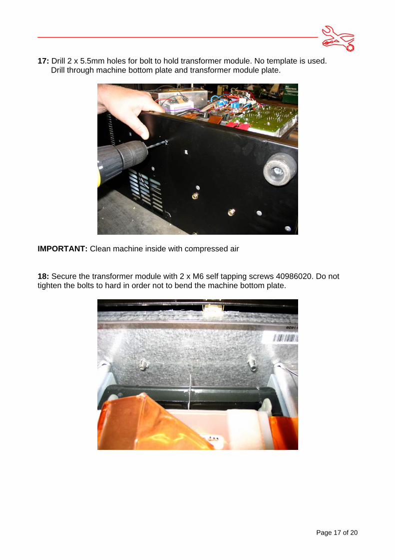
17: Drill 2 x 5.5mm holes for bolt to hold transformer module. No template is used. Drill through machine bottom plate and transformer module plate.
IMPORTANT: Clean machine inside with compressed air
18: Secure the transformer module with 2 x M6 self tapping screws 40986020. Do nottighten the bolts to hard in order not to bend the machine bottom plate.
Page 18 of 20
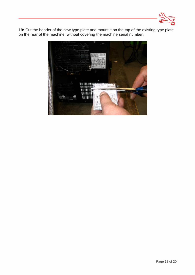
19: Cut the header of the new type plate and mount it on the top of the existing type plateon the rear of the machine, without covering the machine serial number.

Page 19 of 20
20: Exchange the control-box e-proms to version 1.12. Slide a clip not over each hole for the front panel screws. Mount the control box using 4screws 40855016.
21: Check that all connections and plugs are mounted correct and secure. Ensure that all terminals and connections are in a distance of at least 6mm from cabinet.Mount all panels.
22: Perform 500V dc insulation test.
23: Test the machine: Measure OCV to minimum 90 V dc, maximum 113V dc.Perform a welding test in TIG mode.
Page 20 of 20
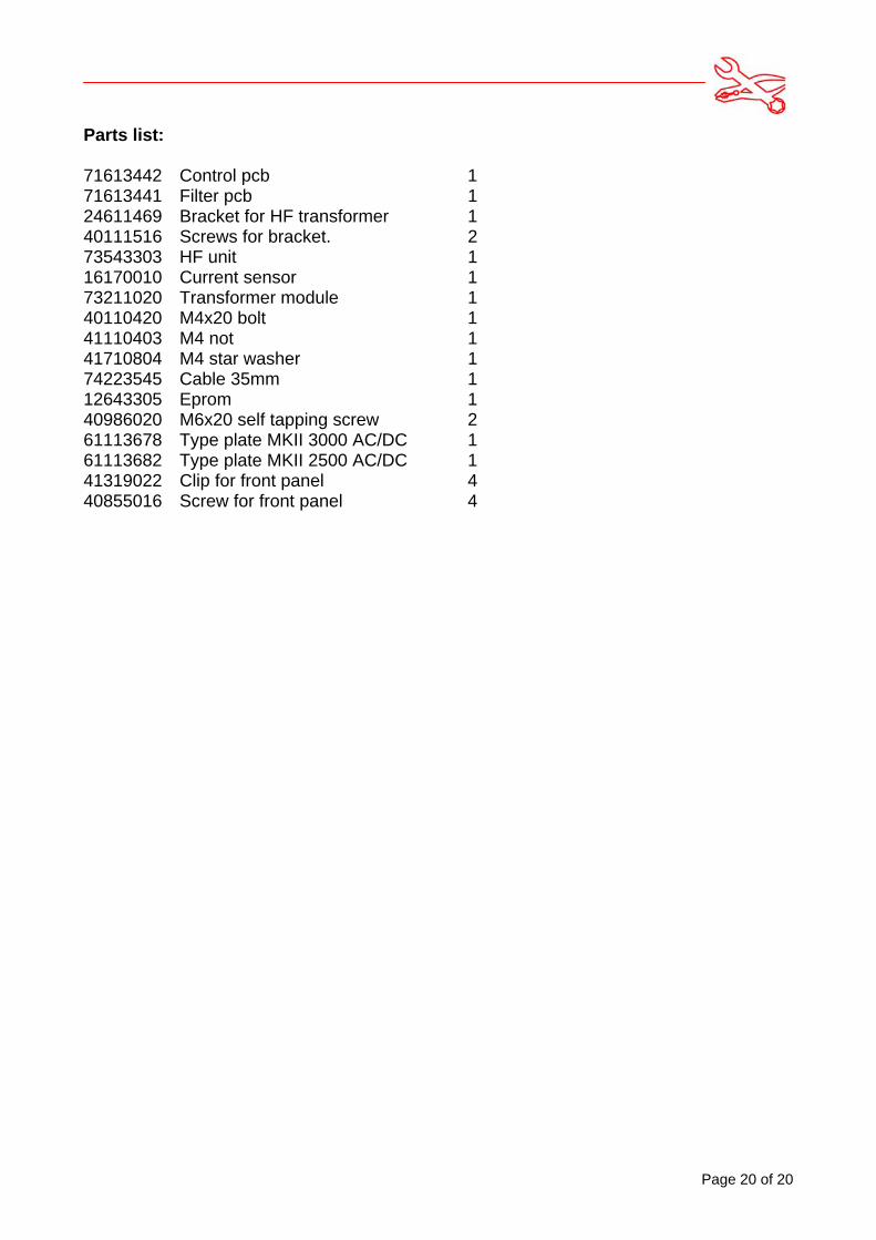
Parts list:
71613442 Control pcb 171613441 Filter pcb 124611469 Bracket for HF transformer 140111516 Screws for bracket. 273543303 HF unit 116170010 Current sensor 173211020 Transformer module 140110420 M4x20 bolt 141110403 M4 not 141710804 M4 star washer 174223545 Cable 35mm 112643305 Eprom 140986020 M6x20 self tapping screw 261113678 Type plate MKII 3000 AC/DC 161113682 Type plate MKII 2500 AC/DC 141319022 Clip for front panel 440855016 Screw for front panel 4