Embed Size (px)
Citation preview

National Marine Electronics Association
NMEA 0183
Standard For Interfacing Marine Electronic Devices
Version 3.01 January 1, 2002
COPYRIGHT© NMEA 2002

NMEA 0183 - Standard For Interfacing Marine Electronic Devices
NMEA 0183 Version 3.01 ------------------------------------------------------------------------------ i
CONTENTS PREFACE 1. INTRODUCTION 2. MANUFACTURER'S DOCUMENTATION 3. HARDWARE SPECIFICATION 4. DATA TRANSMISSION 5. DATA FORMAT PROTOCOL 6. DATA CONTENT 7. APPLICATIONS APPENDIX I - Sentences Not Recommended For New Designs APPENDIX II - Glossary of Terms APPENDIX III - Manufacturer's Mnemonic Codes

NMEA 0183 - Standard For Interfacing Marine Electronic Devices
NMEA 0183 Version 3.01 ------------------------------------------------------------------------------ ii
Preface........................................................................................................................................... 1
AVAILABILITY AND UPDATES OF THE STANDARD........................................................................ 1 1. Introduction............................................................................................................................. 2
1.1 SCOPE .................................................................................................................................... 2 1.2 INTENDED APPLICATION AND LIMITATIONS ON USE .............................................................. 2 1.3 DEFINITIONS .......................................................................................................................... 2 1.4 REFERENCES .......................................................................................................................... 2
2. Manufacturer's Documentation.......................................................................................... 3 3. Hardware Specification........................................................................................................ 4
3.1 INTERCONNECTING WIRE....................................................................................................... 4 3.2 CONDUCTOR DEFINITIONS ..................................................................................................... 4 3.3 ELECTRICAL CONNECTIONS/SHIELD REQUIREMENTS ............................................................ 4 3.4 CONNECTOR........................................................................................................................... 4 3.5 ELECTRICAL SIGNAL CHARACTERISTICS................................................................................ 4
3.5.1 Signal State Definitions.................................................................................................. 4 3.5.2 TALKER Drive Circuits ................................................................................................. 4 3.5.3 LISTENER Receive Circuits .......................................................................................... 4 3.5.4 Electrical Isolation......................................................................................................... 5 3.5.5 Maximum Voltage on Bus .............................................................................................. 5
4. Data Transmission................................................................................................................. 6 5. Data Format Protocol ........................................................................................................... 6
5.1 CHARACTERS ......................................................................................................................... 6 5.1.1 Reserved Characters...................................................................................................... 6 5.1.2 Valid Characters............................................................................................................ 6 5.1.3 Undefined Characters.................................................................................................... 6 5.1.4 Character Symbols......................................................................................................... 7
5.2 FIELDS ................................................................................................................................... 7 5.2.1 Address Field ................................................................................................................. 7 5.2.2 Data Fields..................................................................................................................... 8 5.2.3 Checksum Field.............................................................................................................. 8 5.2.4 Sequential Message Identifier Field ............................................................................... 9
5.3 SENTENCES ............................................................................................................................ 9 5.3.1 Description of Approved Sentences ............................................................................... 9 5.3.2 Parametric Sentences................................................................................................... 10 5.3.3 Encapsulation Sentences.............................................................................................. 11 5.3.4 Query Sentences........................................................................................................... 13 5.3.5 Proprietary Sentences.................................................................................................. 14 5.3.6 Valid Sentences ............................................................................................................ 14 5.3.7 Multi-sentence Messages ............................................................................................. 14 5.3.8 Sentence Transmission Timing .................................................................................... 15 5.3.9 Future Additions to Approved Sentences..................................................................... 15
5.4 ERROR DETECTION AND HANDLING..................................................................................... 15 6. Data Content ......................................................................................................................... 16
TABLE 1 - RESERVED CHARACTERS ............................................................................... 16

NMEA 0183 - Standard For Interfacing Marine Electronic Devices
NMEA 0183 Version 3.01 ------------------------------------------------------------------------------ iii
TABLE 2 - VALID CHARACTERS ....................................................................................... 16 TABLE 3 - CHARACTER SYMBOL TABLE........................................................................ 17 TABLE 4 - TALKER IDENTIFIER MNEMONICS ............................................................... 18 TABLE 5 - APPROVED SENTENCE FORMATTERS (PARAMETRIC FOLLOWED BY ENCAPSULATION) ...................................................................................................................... 19 TABLE 6 - FIELD TYPE SUMMARY ................................................................................... 22 TABLE 7 - SIX-BIT BINARY FIELD CONVERSION TABLE............................................ 24 6.3 APPROVED PARAMETRIC SENTENCES .................................................................................. 27
Notes: ..................................................................................................................................... 29 Notes: ..................................................................................................................................... 30
6.4 APPROVED ENCAPSULATION SENTENCES ............................................................................ 75 7. Applications .......................................................................................................................... 78
7.1 EXAMPLE PARAMETRIC SENTENCES........................................................................................ 78 7.2 EXAMPLE ENCAPSULATION SENTENCES .................................................................................. 81 TABLE 8 - COPY OF ITU-R M.1371 UAIS (TABLE 15)....................................................... 87 7.3 EXAMPLE RECEIVER DIAGRAMS ............................................................................................. 88
NMEA 0183 - Standard For Interfacing Marine Electronic Devices
NMEA 0183 Version 3.01 ------------------------------------------------------------------------------ 1
Preface NMEA Interface Standards are intended to serve the public interest by facilitating interconnection and interchangeability of equipment, minimizing misunderstanding and confusion between manufacturers, and assisting purchasers in selecting compatible equipment. NMEA interface standards are developed with input from manufacturers, private and government organizations, and equipment operators. The information contained in this standard is intended to meet the needs of users at the time of publication, but users must recognize that as applications and technology change, interface standards must change as well. Users of this document are advised to immediately inform NMEA of any perceived inadequacies in this standard. Standards are adopted by NMEA without regard to whether or not their adoption may involve patents on articles, materials or processes. By such action, NMEA does not assume any liability to any patent owner, nor does it assume any obligation whatever to parties adopting these Standards. This Standard defines electrical signal requirements, data transmission protocol and timing, and specific sentence formats for a 4800-baud serial data bus. For operation at the higher rate of 38,400-baud refer to NMEA Standard 0183-HS. Each bus shall have only a single TALKER but may have multiple LISTENERs. Because of differences in baud rate and other transmission parameters, NMEA 0183 data is not directly compatible with NMEA 0180 or NMEA 0182 Standards. Equipment that is specified by IMO to meet the SOLAS regulations is governed by the requirements of IEC 61162-1: Digital Interfaces, Maritime Navigation and Radiocommunications Equipment and Systems. The IEC Standard is aligned closely with the NMEA 0183 Standard. Where possible, differences between the two documents, and sections that pertain specifically to IEC requirements, are indicated herein by the symbol "*" in the margin. Availability and Updates of the Standard This standard may be modified by action of the NMEA Interface Standards Committee as the need arises. Updates to this Standard are published periodically in: Marine Electronics Journal, Inc. - The Official Journal of the NMEA For subscription information contact the NMEA National Office. For information about this standard, contact: NMEA National Office Telephone: (410) 975-9425 7 Riggs Avenue FAX: (410) 975-9450 Severna Park, MD 21146 E-mail: [email protected] U.S.A. http://www.nmea.org

NMEA 0183 - Standard For Interfacing Marine Electronic Devices
NMEA 0183 Version 3.01 ------------------------------------------------------------------------ 2
1. Introduction 1.1 Scope This standard is developed to permit ready and satisfactory data communication between electronic marine instruments, navigation equipment and communications equipment when interconnected via an appropriate interface. 1.2 Intended Application and Limitations on Use This standard is intended to support one-way serial data transmission from a single TALKER to one or more LISTENERs. This is data in printable ASCII form and may include information such as position, speed, depth, frequency allocation, etc. Typical messages might be 11 to a maximum of 79 characters in length and generally require transmission no more often than once per second. The electrical definitions in this standard are not intended to accommodate high-bandwidth applications such as radar or video imagery, or intensive database or file transfer applications. Since there is no provision for guaranteed delivery of sentences and only limited error-checking capability, this standard should be used with caution in critical applications. 1.3 Definitions 1.3.1 General Common terms are defined in Appendix II, Glossary, of this Standard. Where there is a conflict terms shall be interpreted wherever possible in accordance with the references in Section 1.4. 1.3.2 TALKERs A TALKER is any device that sends data to other devices within this standard. The type of TALKER is identified by a 2-character mnemonic as listed in Section 6.2 (Table 4). 1.3.3 LISTENERs A LISTENER is any device that receives data from another device within this standard. 1.4 References 1.4.1 American National Standards Institute:
ANSI X 3.4-1986 (R1997) Information Systems – Coded Character Sets – 7-Bit American National Standard Code for Information Interchange (7-Bit ASCII)
1.4.2 Electronic Industries Association Standards: ANSI/TIA/EIA-422-B-94 May 1994 (R2000)
1.4.3 International Electrotechnical Commission:
3, rue de Varembe P.O. Box 131 1211 Geneva 20 SWITZERLAND
IEC 61162-1: Digital Interfaces, Maritime Navigation and Radiocommunications Equipment and Systems

NMEA 0183 - Standard For Interfacing Marine Electronic Devices
NMEA 0183 Version 3.01 ------------------------------------------------------------------------ 3
1.4.4 American Practical Navigator, Defense Mapping Agency Hydrographic/Topographic Center, Publication No. 9, DMA Stock No. NVPUB9V1, Volumes I and II 1.4.5 Interface Control Document, Navstar GPS Space Segment/Navigation User Interface. Rockwell
International Corporation Document No. ICD-GPS-200 Revision B (November 30, 1987) 1.4.6 Special Publication No. 60, User's Handbook On Datum Transformations Involving WGS84, First
Edition, June 1994. International Hydrographic Bureau, 7 avenue President J.F. Kennedy, B.P. 445, MC 98011 Monaco Cedex.
1.4.7 International Telecommunication Union (ITU) Recommendations:
A. ITU-R M.493-9, Digital Selective-Calling System For Use In The Maritime Mobile Service. B. ITU-R M.821-1, Optional Expansion of the Digital Selective-Calling System For Use In The
Maritime Mobile Service. C. ITU-R M. 825-3, Characteristics of a Transponder System Using Digital Selective-Calling
Techniques For Use With Vessel Traffic Services and Ship-To-Ship Identification. D. ITU-R M.1371, Technical Characteristics for a Universal Shipborne Automatic Identification
System using Time Division Multiple Access in the VHF Maritime Mobile Band. 1.4.8 GLONASS Interface Control Document, 1995 1.4.9 RTCM SC-104, RTCM Recommended Standards for Differential GNSS (Global Navigation
Satellite Systems) Service, Version 2.2, January 1998 1.4.10 NMEA 0183-HS – 38.4 K-baud Serial Data Standard For Interfacing Marine Electronic Devices,
Version 1.00, July 1, 2000, National Marine Electronics Association, PO Box 3435, New Bern, NC 28564-3435, USA
1.4.11 ISO/IEC 10646-1 (1993-05). Unicode Standard. (See 1.4.12) 1.4.12 "The Unicode Standard, Version 2.0", ISBN 0-201-48345-9, Author: The Unicode Consortium,
Publisher: Addison-Wesley. This is equivalent to the ISO/IEC 10646-1 standard as to Unicode values and tables.
2. Manufacturer's Documentation Operator's manuals or other appropriate literature provided for equipment that is intended to meet the requirements of this standard shall contain the following information:
a) Identification of the A and B signal lines. b) The output drive capability as a TALKER. c) A list of approved sentences, noting unused fields, Proprietary sentences transmitted as a
TALKER, and transmission interval for each sentence. d) The load requirements as a LISTENER. e) A list of sentences and associated data fields that are required as a LISTENER. f) The current software and hardware revision if this is relevant to the interface. g) An electrical description or schematic of the LISTENER/TALKER input/output circuits citing

NMEA 0183 - Standard For Interfacing Marine Electronic Devices
NMEA 0183 Version 3.01 ------------------------------------------------------------------------ 4
actual components and devices used, including connector type and part number. h) The Version No. and date of update of the standard for which compliance is assured.
3. Hardware Specification One TALKER and multiple LISTENERS may be connected in parallel over an interconnecting wire. The number of LISTENERS depends on the output capability and input drive requirements of individual devices. 3.1 Interconnecting Wire Interconnection between devices may be by means of a two-conductor, shielded, twisted-pair wire. 3.2 Conductor Definitions The conductors referred to in this standard are the signal lines "A" and "B", and shield. 3.3 Electrical Connections/Shield Requirements All signal line "A" connections are connected in parallel with all device "A" connections and all signal line "B" connections are connected in parallel with all device "B" connections. The shields of all LISTENER cables should be connected to the TALKER chassis only and should not be connected at each LISTENER. 3.4 Connector No standard connector is specified. Wherever possible readily available commercial connectors should be used. Manufacturers shall provide means for user identification of the connectors used. 3.5 Electrical Signal Characteristics This section describes the electrical characteristics of transmitters and receivers. 3.5.1 Signal State Definitions The idle, marking, logical "1", OFF or stop bit state is defined by a negative voltage on line "A" with respect to line "B". The active, spacing, logical "0", ON or start bit state is defined by a positive voltage on line "A" with respect to line "B". Note that the above "A" with respect to "B" levels are inverted from the voltage input/output requirements of standard UARTs and that many line drivers and receivers provide a logic inversion. 3.5.2 TALKER Drive Circuits No provision is made for more than a single TALKER to be connected to the bus. The drive circuit used to provide the signal "A" and the return "B" shall meet, at a minimum, the requirements of EIA-422-A (December 1978). 3.5.3 LISTENER Receive Circuits Multiple LISTENERs may be connected to a single TALKER. The LISTENER receive circuit shall

NMEA 0183 - Standard For Interfacing Marine Electronic Devices
consist of an optoisolator and should have protective circuits to limit current, reverse bias and power dissipation at the optodiode as shown in Figure 1. Reference is made to example circuits in Section 7.2 of this Standard. The receive circuit shall be designed for operation with a minimum differential input voltage of 2.0 Volts and shall not take more than 2.0 mA from the line at that voltage. For reasons of compatibility with equipment designed to earlier versions of this standard, it is noted that the "idle, marking, logical "1", OFF or stop bit state" had previously been defined to be in the range -15 to + 0.5 Volts. The "active, spacing, logical "0", ON or start bit state" was defined to be in the range +4.0 to +15 Volts while sourcing not less than 15 mA.
OPTO-ISOLATORA
BAB
LISTENER 1TALKER
PROTECTIVECIRCUITS
OPTO-ISOLATORA
B
LISTENER 2
PROTECTIVECIRCUITS
SHIELDS
FIGURE 1
3.5.4 Electrical Isolation Within a LISTENER there shall be no direct electrical connection between the signal line, "A", return line, "B", or shield and ship's ground or power. Isolation from ship's ground is required. 3.5.5 Maximum Voltage on Bus The maximum applied voltage between signal lines "A" and "B" and between either line and Ground shall be in accordance with the EIA-422 specification. For protection against miswiring and for use with earlier TALKER designs, all receive circuit devices should be capable of withstanding 15 volts between signal lines "A" and "B" and between either line and ground for an indefinite period.
NMEA 0183 Version 3.01 ------------------------------------------------------------------------ 5

NMEA 0183 - Standard For Interfacing Marine Electronic Devices
4. Data Transmission Data is transmitted in serial asynchronous form in accordance with ANSI standards (reference paragraph 1.4.1). The first bit is a start bit and is followed by data bits, least-significant-bit first as illustrated by Figure 2. The following parameters are used:
Baud rate 4800 Data bits 8 (d7 = 0) Parity None Stop bits One
D0 D1 D2 D3 D4 D5 D6 D7
START DATA BITS STOP BIT BIT
FIGURE 2 5. Data Format Protocol 5.1 Characters All transmitted data shall be interpreted as ASCII characters. The most significant bit of the 8-bit character shall always be transmitted as zero (d7 = 0). 5.1.1 Reserved Characters The reserved character set consists of those ASCII characters shown in Section 6.1 (Table 1). These characters are used for specific formatting purposes, such as sentence and field delimiting, and except for code delimiting shall not be used in data fields. 5.1.2 Valid Characters The valid character set consists of all printable ASCII characters (HEX 20 to HEX 7E) except those defined as reserved characters. Section 6.1 (Table 2) lists the valid character set. 5.1.3 Undefined Characters ASCII values not specified as either "reserved characters" or "valid characters" are excluded and shall not be transmitted at any time. When it is necessary to communicate an 8-bit character defined by ISO 8859-1 that is a Reserved Character (Table 1) or not listed in Table 2 as a Valid Character (e.g., in a Proprietary Sentence or text sentence) three characters shall be used. The Reserved Character “^” (HEX 5E) is followed by two ASCII characters (0-9, A-F) representing the HEX value of the character to be communicated. For example, to send heading as “127.5º” transmit: “127.5^F8”
NMEA 0183 Version 3.01 ------------------------------------------------------------------------ 6

NMEA 0183 - Standard For Interfacing Marine Electronic Devices
NMEA 0183 Version 3.01 ------------------------------------------------------------------------ 7
to send the reserved characters <CR><LF> transmit: “^0D^0A” to send the reserved character “^” transmit: “^5E” 5.1.4 Character Symbols When individual characters are used in this standard to define units of measure, indicate the type of data field, type of sentence, etc. they shall be interpreted according to the character symbol table in Section 6.1 (Table 3). 5.2 Fields A field consists of a string of valid characters, or no characters (null field), located between two appropriate delimiter characters. 5.2.1 Address Field An address field is the first field in a sentence and follows the "$" or "!" delimiter, it serves to define the sentence. The "$" delimiter identifies sentences that conform to the conventional parametric and delimited field composition rules found in Section 5.3.2. The "!" delimiter identifies sentences that conform to the special-purpose encapsulation and non-delimited field composition rules found in Section 5.3.3. Characters within the address field are limited to digits and upper case letters. The address field shall not be a null field. Only sentences with the following three types of address fields shall be transmitted: 5.2.1.1 Approved Address Field Approved address fields consist of five digits and upper case letter characters defined by this standard. The first two characters are the TALKER Identifier, listed in Section 6.2 (Table 4).
The Talker Identifier serves to define the nature of the data being transmitted. Devices that have the capability to transmit data from multiple sources shall transmit the appropriate Talker Identifier (e.g., a device with both a GPS receiver and a Loran-C receiver shall transmit GP when the position is GPS based, LC when the position is Loran-C, and IN for integrated navigation shall be used if lines of position from Loran-C and GPS are combined into a position fix). Devices capable of re-transmitting data from other sources shall use the appropriate identifier (e.g., GPS receivers transmitting heading data shall not transmit $GPHCD unless compass heading is actually derived from GPS signals).
The next three characters form the Sentence Formatter used to define the format and the type of data. Section 6.2 (Table 5) and Appendix I list approved Sentence Formatters. 5.2.1.2 Query Address Field The query address consists of five characters and is used for the purpose of requesting transmission of a specific sentence on a separate bus from an identified TALKER. The first two characters are the TALKER Identifier of the device requesting data, the next two characters are the TALKER Identifier of the device being addressed and the final character is the query character "Q". 5.2.1.3 Proprietary Address Field The proprietary address field consists of the proprietary character "P" followed by a three-character Manufacturer's Mnemonic Code, used to identify the TALKER issuing a proprietary sentence, and any additional characters as required. A list of valid Manufacturer's Mnemonic Codes is contained in Appendix III.
NMEA 0183 - Standard For Interfacing Marine Electronic Devices
NMEA 0183 Version 3.01 ------------------------------------------------------------------------ 8
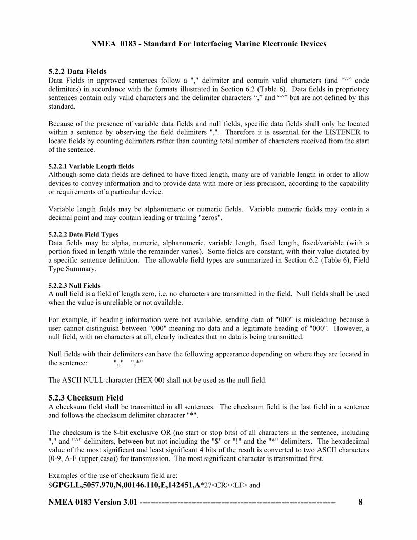
5.2.2 Data Fields Data Fields in approved sentences follow a "," delimiter and contain valid characters (and “^” code delimiters) in accordance with the formats illustrated in Section 6.2 (Table 6). Data fields in proprietary sentences contain only valid characters and the delimiter characters “,” and “^” but are not defined by this standard. Because of the presence of variable data fields and null fields, specific data fields shall only be located within a sentence by observing the field delimiters ",". Therefore it is essential for the LISTENER to locate fields by counting delimiters rather than counting total number of characters received from the start of the sentence. 5.2.2.1 Variable Length fields Although some data fields are defined to have fixed length, many are of variable length in order to allow devices to convey information and to provide data with more or less precision, according to the capability or requirements of a particular device. Variable length fields may be alphanumeric or numeric fields. Variable numeric fields may contain a decimal point and may contain leading or trailing "zeros". 5.2.2.2 Data Field Types Data fields may be alpha, numeric, alphanumeric, variable length, fixed length, fixed/variable (with a portion fixed in length while the remainder varies). Some fields are constant, with their value dictated by a specific sentence definition. The allowable field types are summarized in Section 6.2 (Table 6), Field Type Summary. 5.2.2.3 Null Fields A null field is a field of length zero, i.e. no characters are transmitted in the field. Null fields shall be used when the value is unreliable or not available. For example, if heading information were not available, sending data of "000" is misleading because a user cannot distinguish between "000" meaning no data and a legitimate heading of "000". However, a null field, with no characters at all, clearly indicates that no data is being transmitted. Null fields with their delimiters can have the following appearance depending on where they are located in the sentence: ",," ",*" The ASCII NULL character (HEX 00) shall not be used as the null field. 5.2.3 Checksum Field A checksum field shall be transmitted in all sentences. The checksum field is the last field in a sentence and follows the checksum delimiter character "*". The checksum is the 8-bit exclusive OR (no start or stop bits) of all characters in the sentence, including "," and "^" delimiters, between but not including the "$" or "!" and the "*" delimiters. The hexadecimal value of the most significant and least significant 4 bits of the result is converted to two ASCII characters (0-9, A-F (upper case)) for transmission. The most significant character is transmitted first. Examples of the use of checksum field are: $GPGLL,5057.970,N,00146.110,E,142451,A*27<CR><LF> and
NMEA 0183 - Standard For Interfacing Marine Electronic Devices
NMEA 0183 Version 3.01 ------------------------------------------------------------------------ 9
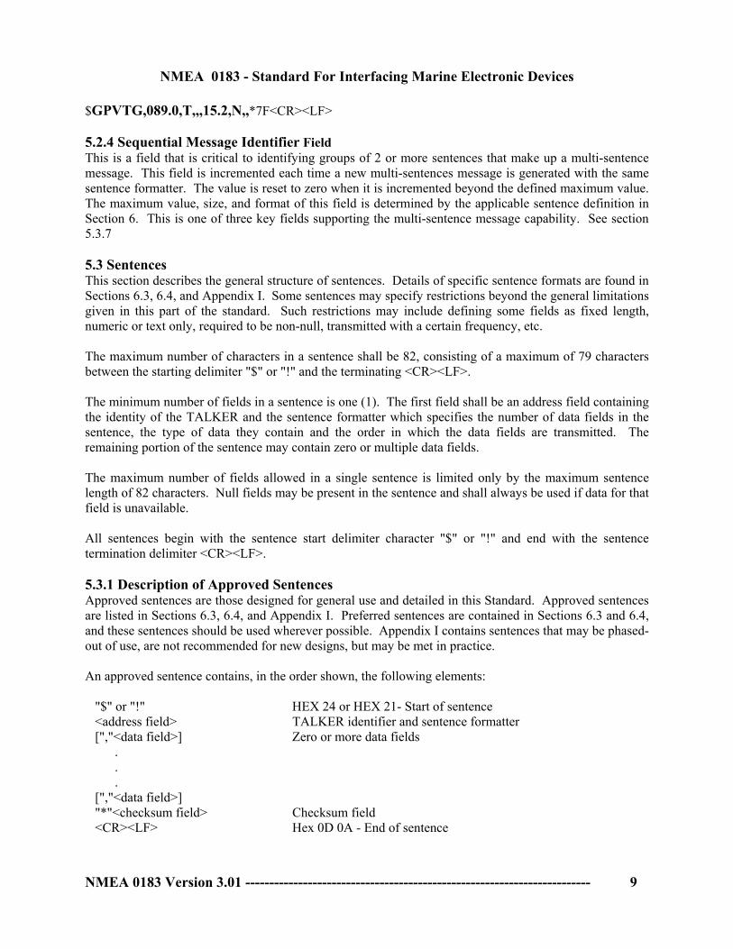
$GPVTG,089.0,T,,,15.2,N,,*7F<CR><LF> 5.2.4 Sequential Message Identifier Field This is a field that is critical to identifying groups of 2 or more sentences that make up a multi-sentence message. This field is incremented each time a new multi-sentences message is generated with the same sentence formatter. The value is reset to zero when it is incremented beyond the defined maximum value. The maximum value, size, and format of this field is determined by the applicable sentence definition in Section 6. This is one of three key fields supporting the multi-sentence message capability. See section 5.3.7 5.3 Sentences This section describes the general structure of sentences. Details of specific sentence formats are found in Sections 6.3, 6.4, and Appendix I. Some sentences may specify restrictions beyond the general limitations given in this part of the standard. Such restrictions may include defining some fields as fixed length, numeric or text only, required to be non-null, transmitted with a certain frequency, etc. The maximum number of characters in a sentence shall be 82, consisting of a maximum of 79 characters between the starting delimiter "$" or "!" and the terminating <CR><LF>. The minimum number of fields in a sentence is one (1). The first field shall be an address field containing the identity of the TALKER and the sentence formatter which specifies the number of data fields in the sentence, the type of data they contain and the order in which the data fields are transmitted. The remaining portion of the sentence may contain zero or multiple data fields. The maximum number of fields allowed in a single sentence is limited only by the maximum sentence length of 82 characters. Null fields may be present in the sentence and shall always be used if data for that field is unavailable. All sentences begin with the sentence start delimiter character "$" or "!" and end with the sentence termination delimiter <CR><LF>. 5.3.1 Description of Approved Sentences Approved sentences are those designed for general use and detailed in this Standard. Approved sentences are listed in Sections 6.3, 6.4, and Appendix I. Preferred sentences are contained in Sections 6.3 and 6.4, and these sentences should be used wherever possible. Appendix I contains sentences that may be phased-out of use, are not recommended for new designs, but may be met in practice. An approved sentence contains, in the order shown, the following elements: "$" or "!" HEX 24 or HEX 21- Start of sentence <address field> TALKER identifier and sentence formatter [","<data field>] Zero or more data fields . . . [","<data field>] "*"<checksum field> Checksum field <CR><LF> Hex 0D 0A - End of sentence

NMEA 0183 - Standard For Interfacing Marine Electronic Devices
NMEA 0183 Version 3.01 ------------------------------------------------------------------------ 10
5.3.2 Parametric Sentences These sentences start with the "$" delimiter, and represent the majority of approved sentences defined by this standard. This sentence structure, with delimited and defined data fields, is the preferred method for conveying information. The basic rules for parametric sentence structures are:
1. The sentence begins with the "$" delimiter. 2. Only approved sentence formatters are allowed. Formatters used by special-purpose
encapsulation sentences cannot be reused. See Section 6.2 (Table 5). 3. Only valid characters are allowed. See Section 6.1 (Tables 1 and 2). 4. Only approved field types are allowed. See Section 6.2 (Table 6). 5. Data fields (parameters) are individually delimited, and their content is identified and often
described in detail by this standard. 6. Encapsulated non-delimited data fields are NOT ALLOWED.
5.3.2.1 Approved Parametric Sentence Structure The following provides a summary explanation of the approved parametric sentence structure: $aaccc,c--c*hh<CR><LF> ASCII HEX DESCRIPTION "$" 24 Start of Sentence. aaccc Address Field. Alphanumeric characters identifying type of TALKER,
and Sentence Formatter. The first two characters identify the TALKER. The last three are the Sentence Formatter mnemonic code identifying the data type and the string format of the successive fields. Mnemonics will be used as far as possible to facilitate readouts by users.
"," 2C Field delimiter. Starts each field except address and checksum fields.
If it is followed by a null field, it is all that remains to indicate no data in a field.
c--c Data Sentence block. Follows address field and is a series of data
fields containing all of the data to be transmitted. Data field sequence is fixed and identified by 3rd and subsequent characters of the address field (the "Sentence Formatter"). Data fields may be of variable length and are preceded by delimiters ",".
"*" 2A Checksum Delimiter. Follows last data field of the sentence.
It indicates that the following two alphanumeric characters show the HEX value of the Checksum.

NMEA 0183 - Standard For Interfacing Marine Electronic Devices
NMEA 0183 Version 3.01 ------------------------------------------------------------------------ 11
hh Checksum Field. The absolute value calculated by exclusive-OR'ing
the 8 data bits (no start bits or stop bits) of each character in the Sentence, between, but excluding "$" and "*". The hexadecimal value of the most significant and least significant 4 bits of the result are converted to two ASCII characters (0-9, A-F (upper case)) for transmission. The most significant character is transmitted first. The Checksum field is required in all transmitted sentences.
<CR><LF> 0D 0A Terminates Sentence. 5.3.3 Encapsulation Sentences These sentences start with the "!" delimiter. The function of this special-purpose sentence structure is to provide a means to convey information, when the specific data content is unknown or greater information bandwidth is needed. This is similar to a modem that transfers information without knowing how the information is to be decoded or interpreted. The basic rules for encapsulation sentence structures are:
1. The sentence begins with the "!" delimiter. 2. Only approved sentence formatters are allowed. Formatters used by conventional parametric
sentences can not be reused. See Section 6.2 (Table 5). 3. Only valid characters are allowed. See Section 6.1 (Tables 1 and 2). 4. Only approved field types are allowed. See Section 6.2 (Table 6). 5. Only Six bit coding may be used to create encapsulated data fields. See Section 6.2 (Table 6). 6. Encapsulated data fields may consist of any number of parameters, and their content is not
identified or described by this standard. 7. The sentence must be defined with one encapsulated data field and any number of parametric
data fields separated by the "," data field delimiter. The encapsulated data field shall always be the second to last data field in the sentence, not counting the checksum field. See Section 5.2.2.
8. The sentence contains a "Total Number Of Sentences" field. See Section 5.3.3.1. 9. The sentence contains a "Sentence Number" field. See Section 5.3.3.1. 10. The sentence contains a "Sequential Message Identifier" field. See Section 5.3.3.1. 11. The sentence contains a "Fill Bits" field immediately following the encapsulated data field.
The Fill Bits field shall always be the last data field in the sentence, not counting the checksum field. See Section 5.3.3.1.
Note: This method to convey information is to be used only when absolutely necessary, and will only be considered when one or both of two conditions are true, and when there is no alternative. Condition 1: The data parameters are unknown by devices having to convey the information. For
example, the ABM and BBM sentences meet this condition, because the content is not known to the Universal Automatic Identification System (UAIS) transponder.

NMEA 0183 - Standard For Interfacing Marine Electronic Devices
NMEA 0183 Version 3.01 ------------------------------------------------------------------------ 12
Condition 2: When information requires a significantly higher data rate than can be achieved by the NMEA 0183 (4,800baud) and NMEA 0183-HS (38,400baud) standards utilizing parametric sentences.
By encapsulating a large amount of information, the number of overhead characters, such as "," field delimiters can be reduced, resulting in higher data transfer rates. It is very unusual for this second condition to be fulfilled. As an example, a UAIS transponder has a data rate capability of 4,500 messages per minute, and satisfies this condition, resulting in the VDM and VDO sentences.
5.3.3.1 Approved Encapsulation Sentence Structure The following provides a summary explanation of the approved encapsulation sentence structure: !aaccc,x1,x2,x3,c--c,x4*hh<CR><LF> ASCII HEX DESCRIPTION "!" 21 Start of Sentence. aaccc Address Field. Alphanumeric characters identifying type of TALKER,
and Sentence Formatter. The first two characters identify the TALKER. The last three are the Sentence Formatter mnemonic code identifying the data type and the string format of the successive fields. Mnemonics will be used as far as possible to facilitate readouts by users.
"," 2C Field delimiter. Starts each field except address and checksum fields.
If it is followed by a null field, it is all that remains to indicate no data in a field.
x1 Total Number Of Sentences field. Encapsulated information often requires
more than one sentence. This field represents the total number of encapsulated sentences needed. This may be fixed or variable length, and is defined by the sentence definitions in Section 6.4.
x2 Sentence Number field. Encapsulated information often requires more than
one sentence. This field identifies which sentence of the total number of sentences this is. This may be fixed or variable length, and is defined by the sentence definitions in Section 6.4.
x3 Sequential Message Identifier field. This field distinguishes one encapsulated
message consisting of one or more sentences, from another encapsulated message using the same sentence formatter. This field is incremented each time an encapsulated message is generated with the same formatter as a previously encapsulated message. The value is reset to zero when it is incremented beyond the defined maximum value. The maximum value and

NMEA 0183 - Standard For Interfacing Marine Electronic Devices
NMEA 0183 Version 3.01 ------------------------------------------------------------------------ 13
size of this field is determined by the applicable sentence definitions in Section 6.4.
c--c Data Sentence block. Follows sequential message identifier field and is a
series of data fields consisting of one or more parametric data fields and one encapsulated data field. Data field sequence is fixed and identified by 3rd and subsequent characters of the address field (the "Sentence Formatter"). Individual data fields may be of variable length and are preceded by delimiters ",". The encapsulated data field shall always be the second to last data field in the sentence.
x4 Fill Bits field. This field represents the number of fill bits added to complete
the last Six bit coded character. This field is required and shall immediately follow the encapsulated data field. To encapsulate, the number of binary bits must be a multiple of six. If it is not, one to five Fill Bits are added. This field shall be set to zero when no Fill Bits have been added. The Fill Bits field shall always be the last data field in the sentence. This shall not be a null field.
"*" 2A Checksum Delimiter. Follows last data field of the sentence.
It indicates that the following two alphanumeric characters show the HEX value of the Checksum.
hh Checksum Field. The absolute value calculated by exclusive-OR'ing
the 8 data bits (no start bits or stop bits) of each character in the Sentence, between, but excluding "!" and "*". The hexadecimal value of the most significant and least significant 4 bits of the result are converted to two ASCII characters (0-9, A-F (upper case)) for transmission. The most significant character is transmitted first. The Checksum field is required in all transmitted sentences.
<CR><LF> 0D 0A Terminates Sentence. 5.3.4 Query Sentences Query sentences are intended to request Approved sentences to be transmitted in a form of two-way communication. The use of query sentences implies that the LISTENER shall have the capability of being a TALKER with its own bus. Query sentences shall always be constructed with the "$" - Start of sentence delimiter. The approved Query sentence contains, in the order shown, the following elements: "$" HEX 24 - Start of sentence <aa> TALKER Identifier of requester <aa> TALKER Identifier for device from which data is being requested "Q" Query character identifies Query address

NMEA 0183 - Standard For Interfacing Marine Electronic Devices
NMEA 0183 Version 3.01 ------------------------------------------------------------------------ 14
"," Data field delimiter <ccc> Approved sentence formatter of data being requested "*"<checksum field> Checksum field <CR><LF> HEX 0D 0A - End of sentence 5.3.4.1 Reply To Query Sentence The reply to a Query sentence is the Approved sentence that was requested. The use of Query sentences requires cooperation between the devices that are interconnected, a reply to a Query sentence is not mandatory and there is no specified time delay between the receipt of a query and the reply. 5.3.5 Proprietary Sentences Proprietary sentences provide a means for manufacturers to use the sentence structure definitions of this standard to transfer data which does not fall within the scope of approved sentences. This will generally be for one of the following reasons:
a) Data is intended for another device from the same manufacturer, is device specific, and not in a form or of a type of interest to the general user;
b) Data is being used for test purposes prior to the adoption of approved sentences; c) Data is not of a type and general usefulness which merits the creation of an approved sentence.
A proprietary sentence contains, in the order shown, the following elements: "$" or "!" Hex 24 or Hex 21- Start of sentence "P" Hex 50 - Proprietary sentence ID <aaa> Manufacturer's Mnemonic code [<valid characters>, “^”, “,”] Manufacturer's data "*"<checksum field> Checksum field <CR><LF> Hex 0D 0A - End of sentence Proprietary sentences shall include checksums and conform to requirements limiting overall sentence length. Manufacturer’s data fields shall contain only valid-character but may include “^” and “,” for delimiting or as manufacturer’s data. Details of proprietary data fields are not included in this standard and need not be submitted for approval, however it is required that such sentences be published in the manufacturer's manuals for reference. 5.3.6 Valid Sentences Approved sentences (Parametric & Encapsulation), Query sentences and Proprietary sentences are the only valid sentences. Sentences of any other form are non-valid and shall not be transmitted on the bus. 5.3.7 Multi-sentence Messages Multi-sentence messages may be transmitted where a data message exceeds the available character space in a single sentence. The key fields supporting the multi-sentence message capability shall always be included, without exception. These required fields are: total number of sentences, sentence number, and sequential message identifier fields. Only sentence definitions containing these fields may be used to form messages. The TUT and VDN sentences are good examples of how a sentence is defined to provide these capabilities.

NMEA 0183 - Standard For Interfacing Marine Electronic Devices
NMEA 0183 Version 3.01 ------------------------------------------------------------------------ 15
The Listener should be aware that a multi-sentence message may be interrupted by a higher priority message such as an alarm sentence, and thus the original message should be discarded as incomplete and has to await a re-transmission. The Listener has to check that multi-sentences are contiguous. Should an error occur in any sentence of a multi-sentence message, the Listener shall discard the whole message and be prepared to receive the message again upon the next transmission. 5.3.8 Sentence Transmission Timing Frequency of sentence transmission when specified shall be in accordance with the approved sentence definitions (Sections 6.3, 6.4, and Appendix I). When not specified, the rate should be consistent with the basic measurement or calculation cycle but generally not more frequently than once per second. It is desirable that sentences be transmitted with minimum inter-character spacing, preferably as a near continuous burst, but under no circumstance shall the time to complete the transmission of a sentence be greater than 1 second. 5.3.9 Future Additions to Approved Sentences In order to allow for improvements or additions, future revisions of this Standard may modify existing sentences by adding new data fields after the last data field but before the checksum delimiter character "*" and checksum field. LISTENERs should determine the end of the sentence by recognition of <CR><LF> and "*" rather than by counting field delimiters. The checksum value shall be computed on all received characters between, but not including, "$" or "!" and "*" whether or not the LISTENER recognizes all fields. 5.4 Error Detection and Handling Listening devices shall detect errors in data transmission including:
a) Checksum error b) Invalid characters c) Incorrect length of TALKER identifier, sentence formatter, and data fields d) Time out of sentence transfer.
Listening devices shall use only correct sentences, consistent with the version of NMEA 0183 supported by the Talker devices.
NMEA 0183 - Standard For Interfacing Marine Electronic Devices
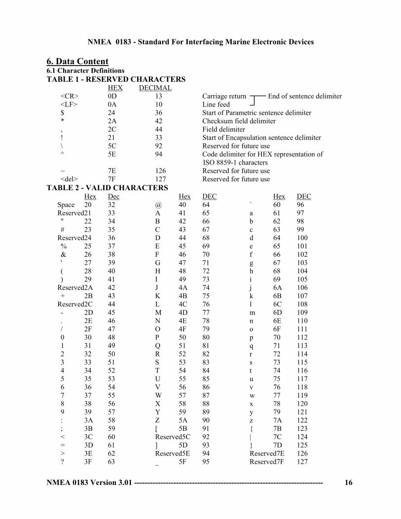
6. Data Content 6.1 Character Definitions TABLE 1 - RESERVED CHARACTERS HEX DECIMAL
<CR> 0D 13 Carriage return End of sentence delimiter <LF> 0A 10 Line feed $ 24 36 Start of Parametric sentence delimiter * 2A 42 Checksum field delimiter , 2C 44 Field delimiter ! 21 33 Start of Encapsulation sentence delimiter \ 5C 92 Reserved for future use ^ 5E 94 Code delimiter for HEX representation of
ISO 8859-1 characters ~ 7E 126 Reserved for future use <del> 7F 127 Reserved for future use
TABLE 2 - VALID CHARACTERS Hex Dec Hex DEC Hex DEC Space 20 32 @ 40 64 ` 60 96 Reserved21 33 A 41 65 a 61 97
" 22 34 B 42 66 b 62 98 # 23 35 C 43 67 c 63 99
Reserved24 36 D 44 68 d 64 100 % 25 37 E 45 69 e 65 101 & 26 38 F 46 70 f 66 102 ' 27 39 G 47 71 g 67 103 ( 28 40 H 48 72 h 68 104 ) 29 41 I 49 73 i 69 105
Reserved2A 42 J 4A 74 j 6A 106 + 2B 43 K 4B 75 k 6B 107
Reserved2C 44 L 4C 76 l 6C 108 - 2D 45 M 4D 77 m 6D 109 . 2E 46 N 4E 78 n 6E 110 / 2F 47 O 4F 79 o 6F 111 0 30 48 P 50 80 p 70 112 1 31 49 Q 51 81 q 71 113 2 32 50 R 52 82 r 72 114 3 33 51 S 53 83 s 73 115 4 34 52 T 54 84 t 74 116 5 35 53 U 55 85 u 75 117 6 36 54 V 56 86 v 76 118 7 37 55 W 57 87 w 77 119 8 38 56 X 58 88 x 78 120 9 39 57 Y 59 89 y 79 121 : 3A 58 Z 5A 90 z 7A 122 ; 3B 59 [ 5B 91 { 7B 123 < 3C 60 Reserved5C 92 | 7C 124 = 3D 61 ] 5D 93 } 7D 125 > 3E 62 Reserved5E 94 Reserved7E 126 ? 3F 63 _ 5F 95 Reserved7F 127
NMEA 0183 Version 3.01 ------------------------------------------------------------------------ 16

NMEA 0183 - Standard For Interfacing Marine Electronic Devices
NMEA 0183 Version 3.01 ------------------------------------------------------------------------ 17
6.1 Character Definitions (continued) TABLE 3 - CHARACTER SYMBOL TABLE A Status symbol; Yes; Data Valid; Warning Flag Clear; Auto; Ampere; ASCII a Alphabet character variable A through Z or a through z B Bars (pressure, 1000 Mb = 1 Std. Atm. = 100kPa); Bottom C Celsius (Degrees); Course-up c Valid character; Calculating D Degrees (of Arc) E Error; East; Engine F Fathoms f Feet G Great Circle; Green g Good H Compass Heading; Head-up; Hertz; Humidity h Hours; HEX number I Inches J Input operation completed K Kilometers; km/hour k Kilograms L Left; Local; Lost Target l Latitude; Liters; Liters/second M Meters; Meters/second; Magnetic; Manual; Cubic Meters m Minutes; message N Nautical miles; Knots; North; North-up; Newton n Numeral; address P Purple; Proprietary (only when following $); Position sensor; Percent; Pascal (pressure) Q Query; Target-Being-Acquired R Right; Rhumb line; Red; Relative; Reference; Radar Tracking; Rev/min (RPM) S South; Statute miles; Statute miles/hour; Shaft; Salinity in parts per thousand s Seconds; Six bit number T Time difference; True; Track; Tracked-Target t Test U Dead Reckoning Estimate u Sign, if minus "-" (HEX 2D) V Data invalid; No; Warning Flag Set; Manual; Volt W West; Water; Wheelover x Numeric character variable y Longitude Z Time

NMEA 0183 - Standard For Interfacing Marine Electronic Devices
NMEA 0183 Version 3.01 ------------------------------------------------------------------------ 18
6.2 Field Definitions
TABLE 4 - TALKER IDENTIFIER MNEMONICS (Address Characters 1 and 2) TALKER DEVICE IDENTIFIER Heading Track Controller (Autopilot): General AG* Magnetic AP Automatic Identification System AI COMMUNICATIONS: Digital Selective Calling (DSC) CD* Data Receiver CR Satellite CS* Radio-Telephone (MF/HF) CT* Radio-Telephone (VHF) CV* Scanning Receiver CX* DECCA Navigator DE Direction Finder DF*
Electronic Chart System (ECS) EC Electronic Chart Display & Information System (ECDIS) EI Emergency Position Indicating Beacon (EPIRB) EP* Engine room Monitoring Systems ER GLONASS Receiver GL Global Navigation Satellite System (GNSS) GN Global Positioning System (GPS) GP HEADING SENSORS: Compass, Magnetic HC* Gyro, North Seeking HE* Gyro, Non-North Seeking HN Integrated Instrumentation II Integrated Navigation IN Loran C LC Proprietary Code P Radar and/or Radar Plotting RA* Sounder, depth SD* Electronic Positioning System, other/general SN Sounder, scanning SS Turn Rate Indicator TI* VELOCITY SENSORS: Doppler, other/general VD* Speed Log, Water, Magnetic VM Speed Log, Water, Mechanical VW Voyage Data Recorder VR Transducer YX TIMEKEEPERS, TIME/DATE: Atomic Clock ZA Chronometer ZC Quartz ZQ Radio Update ZV Weather Instruments WI *Designated by IEC for use with IMO maritime electronic devices. This is the minimum
requirement for equipment that is required by IMO in the SOLAS Convention (1974, as amended).

NMEA 0183 - Standard For Interfacing Marine Electronic Devices
NMEA 0183 Version 3.01 ------------------------------------------------------------------------ 19
6.2 Field Definitions TABLE 5 - APPROVED SENTENCE FORMATTERS (Parametric followed by Encapsulation) Parametric Formatters ....................................................................................................................27 AAM - Waypoint Arrival Alarm....................................................................................................27 ABK - UAIS Addressed and binary broadcast acknowledgement ................................................27 ACA - UAIS Regional Channel Assignment Message..................................................................28 ACK – Acknowledge Alarm..........................................................................................................30 ACS – UAIS Channel management information Source ...............................................................30 AIR - UAIS Interrogation Request.................................................................................................30 ALM - GPS Almanac Data ............................................................................................................31 ALR – Set Alarm State...................................................................................................................32 APB - Heading/Track Controller (Autopilot) Sentence "B"..........................................................33 BEC - Bearing & Distance to Waypoint - Dead Reckoning ..........................................................33 BOD - Bearing - Origin to Destination ..........................................................................................34 BWC - Bearing & Distance to Waypoint.......................................................................................34 BWR - Bearing & Distance to Waypoint - Rhumb Line ...............................................................34 BWW - Bearing - Waypoint to Waypoint......................................................................................34 CUR – Water Current Layer ..........................................................................................................35 DBT - Depth Below Transducer ....................................................................................................35 DCN - Decca Position ....................................................................................................................36 *DPT - Depth .................................................................................................................................36 *DSC - Digital Selective Calling Information ...............................................................................36 DSE - Expanded Digital Selective Calling ....................................................................................37 DSI - DSC Transponder Initialize..................................................................................................38 DSR - DSC Transponder Response ...............................................................................................39 *DTM - Datum Reference..............................................................................................................40 *FSI - Frequency Set Information..................................................................................................40 GBS - GNSS Satellite Fault Detection...........................................................................................41 GGA - Global Positioning System Fix Data ..................................................................................42 GLC - Geographic Position - Loran-C...........................................................................................43 GLL - Geographic Position - Latitude/Longitude..........................................................................43 GMP -GNSS Map Projection Fix Data ..........................................................................................43 GNS -GNSS Fix Data ....................................................................................................................45 GRS - GNSS Range Residuals.......................................................................................................47 GSA - GNSS DOP and Active Satellites .......................................................................................48 GST - GNSS Pseudorange Error Statistics ....................................................................................49 GSV - GNSS Satellites in View.....................................................................................................49 *HDG - Heading, Deviation & Variation ......................................................................................50 *HDT - Heading, True ...................................................................................................................50 *HMR - Heading Monitor Receive................................................................................................51 *HMS - Heading Monitor Set ........................................................................................................51 HSC - Heading Steering Command ...............................................................................................51

NMEA 0183 - Standard For Interfacing Marine Electronic Devices
NMEA 0183 Version 3.01 ------------------------------------------------------------------------ 20
*HTC - Heading/Track Control Command....................................................................................52 *HTD - Heading/Track Control Data.............................................................................................52 LCD - Loran-C Signal Data ...........................................................................................................53 LRF - UAIS Long-Range Function................................................................................................53 LRI - UAIS Long-Range Interrogation..........................................................................................54 LR1 - UAIS Long-range Reply Sentence 1 ...................................................................................55 LR2 - UAIS Long-range Reply Sentence 2 ...................................................................................55 LR3 - UAIS Long-range Reply Sentence 3 ...................................................................................56 MLA - GLONASS Almanac Data .................................................................................................57 MSK - MSK Receiver Interface.....................................................................................................58 MSS - MSK Receiver Signal .........................................................................................................58 MTW - Water Temperature............................................................................................................58 MWD - Wind Direction & Speed ..................................................................................................58 MWV - Wind Speed and Angle .....................................................................................................59 *OSD - Own Ship Data..................................................................................................................59 RMA - Recommended Minimum Specific Loran-C Data .............................................................60 RMB - Recommended Minimum Navigation Information............................................................60 RMC - Recommended Minimum Specific GNSS Data.................................................................61 *ROT - Rate Of Turn .....................................................................................................................62 *RPM - Revolutions.......................................................................................................................62 *RSA - Rudder Sensor Angle ........................................................................................................62 *RSD - Radar System Data............................................................................................................63 RTE - Routes RTE - Routes...........................................................................................................63 *SFI - Scanning Frequency Information........................................................................................64 SSD - UAIS Ship Static Data.........................................................................................................65 STN - Multiple Data ID .................................................................................................................65 TLB - Target Label ........................................................................................................................66 TLL - Target Latitude and Longitude ............................................................................................66 *TTM - Tracked Target Message...................................................................................................66 TUT – Transmission of Multi-language Text ................................................................................67 TXT - Text Transmission...............................................................................................................69 *VBW - Dual Ground/Water Speed...............................................................................................69 VDR - Set and Drift .......................................................................................................................69 VHW - Water Speed and Heading .................................................................................................70 VLW - Dual Ground/Water Distance.............................................................................................70 VPW - Speed - Measured Parallel to Wind....................................................................................70 VSD - UAIS Voyage Static Data ...................................................................................................70 VTG - Course Over Ground and Ground Speed ............................................................................71 WCV - Waypoint Closure Velocity ...............................................................................................72 WNC - Distance - Waypoint to Waypoint .....................................................................................72 WPL - Waypoint Location .............................................................................................................72 XDR - Transducer Measurements..................................................................................................72 XTE - Cross-Track Error, Measured..............................................................................................73 XTR - Cross-Track Error - Dead Reckoning .................................................................................74 ZDA - Time & Date .......................................................................................................................74 ZDL - Time and Distance to Variable Point ..................................................................................74

NMEA 0183 - Standard For Interfacing Marine Electronic Devices
NMEA 0183 Version 3.01 ------------------------------------------------------------------------ 21
ZFO - UTC & Time from Origin Waypoint ..................................................................................75 ZTG - UTC & Time to Destination Waypoint ...............................................................................75 Encapsulation Formatters...............................................................................................................75 ABM - UAIS Addressed binary and safety related message. ........................................................75 BBM - UAIS Broadcast Binary Message. .....................................................................................76 VDM - UAIS VHF Data-link Message..........................................................................................77 VDO - UAIS VHF Data-link Own-vessel report ...........................................................................78 *Designated by IEC for use with IMO maritime electronic devices as required by IMO in the
SOLAS convention (1974 as amended).

NMEA 0183 - Standard For Interfacing Marine Electronic Devices
NMEA 0183 Version 3.01 ------------------------------------------------------------------------ 22
6.2 Field Definitions TABLE 6 - FIELD TYPE SUMMARY Field Type Symbol Definition Special Format Fields:
Status A Single character field: A = Yes, Data Valid, Warning Flag Clear V = No, Data Invalid, Warning Flag Set
Latitude llll.ll Fixed/Variable length field:
degreesminutes.decimal - 2 fixed digits of degrees, 2 fixed digits of minutes and a variable number of digits for decimal-fraction of minutes. Leading zeros always included for degrees and minutes to maintain fixed length. The decimal point and associated decimal-fraction are optional if full resolution is not required.
Longitude yyyyy.yy Fixed/Variable length field:
degreesminutes.decimal - 3 fixed digits of degrees, 2 fixed digits of minutes and a variable number of digits for decimal-fraction of minutes. Leading zeros always included for degrees and minutes to maintain fixed length. The decimal point and associated decimal-fraction are optional if full resolution is not required.
Time hhmmss.ss Fixed/Variable length field:
hoursminutesseconds.decimal - 2 fixed digits of hours, 2 fixed digits of minutes, 2 fixed digits of seconds and a variable number of digits for decimal-fraction of seconds. Leading zeros always included for hours, minutes and seconds to maintain fixed length. The decimal point and associated decimal-fraction are optional if full resolution is not required.
Defined field Some fields are specified to contain pre-defined
constants, most often alpha characters. Such a field is indicated in this standard by the presence of one or more valid characters. Excluded from the list of allowable characters are the following that are used to indicate field types within this standard: "A", "a", "c", "hh", "hhmmss.ss", "llll.ll", "x", "yyyyy.yy"

NMEA 0183 - Standard For Interfacing Marine Electronic Devices
NMEA 0183 Version 3.01 ------------------------------------------------------------------------ 23
6.2 Field Definitions TABLE 6 FIELD TYPE SUMMARY (continued) Field Type Symbol Definition Numeric Value Fields: Variable numbers x.x Variable length integer or floating numeric field.
Optional leading and trailing zeros. The decimal point and associated decimal-fraction are optional if full resolution is not required. (example: 73.10 = 73.1 = 073.1 = 73)
Fixed HEX field hh___ Fixed length HEX numbers only, MSB on the left. Variable HEX field h--h Variable length HEX numbers only, MSB on the left. Fixed Six bit field ss___ Fixed length Six bit coded characters only. See Table 7
and Figures 3 & 4 for field conversions. Variable Six bit field s--s Variable length Six bit coded characters only. See Table 7
and Figures 3 & 4 for field conversions. Information Fields: Variable text c--c Variable length valid character field. Fixed alpha field aa___ Fixed length field of upper-case or lower-case alpha
characters Fixed number field xx___ Fixed length field of numeric characters Fixed text field cc___ Fixed length field of valid characters NOTES: 1. Spaces shall only be used in variable text fields. 2. A negative sign "-" (HEX 2D) is the first character in a Field if the value is negative. When used, this
increments the specified size of fixed length fields by one. The sign is omitted if the value is positive. 3. Units of measure fields are appropriate characters from the Symbol Table (Table 3) unless a specific
unit of measure is indicated. 4. Fixed length field definitions show the actual number of characters. For example, a field defined to
have a fixed length of 5 HEX characters is represented as hhhhh between delimiters in a sentence definition.

NMEA 0183 - Standard For Interfacing Marine Electronic Devices
NMEA 0183 Version 3.01 ------------------------------------------------------------------------ 24
TABLE 7 - SIX-BIT BINARY FIELD CONVERSION TABLE Valid Characters (see Table 2) Binary Field, Most Significant Bit on the left. The two MSB's of the Valid Characters are not used. Valid Character Binary Field Valid Character Binary Field 0 000000 P 100000 1 000001 Q 100001 2 000010 R 100010 3 000011 S 100011 4 000100 T 100100 5 000101 U 100101 6 000110 V 100110 7 000111 W 100111 8 001000 ' 101000 9 001001 a 101001 : 001010 b 101010 ; 001011 c 101011 < 001100 d 101100 = 001101 e 101101 > 001110 f 101110 ? 001111 g 101111 @ 010000 h 110000 A 010001 i 110001 B 010010 j 110010 C 010011 k 110011 D 010100 l 110100 E 010101 m 110101 F 010110 n 110110 G 010111 o 110111 H 011000 p 111000 I 011001 q 111001 J 011010 r 111010 K 011011 s 111011 L 011100 t 111100 M 011101 u 111101 N 011110 v 111110 O 011111 w 111111 The six bit binary field conversion can be done mathematically as well as with Table 7. The algorithm to convert a 6-bit binary field to the appropriate 8-bit valid 0183 character field is shown in Figure 3. Similarly, an algorithm can also be used to convert the valid 0183 characters to the 6-bit binary values as shown in Figure 4.

NMEA 0183 - Standard For Interfacing Marine Electronic Devices
6-Bit Binary
Binary <101000 ?
Add00110000
Add00111000
Table 7Valid Character
CODE 6-BIT BINARY VALUETO VALID 0183 CHARACTER
YES NO
FIGURE 3
Consider the following examples: 000001 is less than 101000, therefore add 00110000 00110000 00110001 = 31hex = 1 (see Table 2) 000010 is less than 101000, therefore add 00110000 00110000 00110010 = 32hex = 2 (see Table 2) 111010 is not less than 101000, therefore add 00111000 00111000 01110010 = 72hex = r (see Table 2)
NMEA 0183 Version 3.01 ------------------------------------------------------------------------ 25

NMEA 0183 - Standard For Interfacing Marine Electronic Devices
Table 7Valid Character
Add101000
Sum >10000000
?
Add101000
Add100000
Binary =6 LSB of Sum
DECODE VAILID 0183CHARACTER TO 6-BIT
BINARY VALUE
YESNO
FIGURE 4
Consider the previous examples: The valid character "1" (00110001): 00110001 + 101000 = 01011001 which is not greater than 10000000. Therefore, add 101000 to 01011001 = 10000001 and take the six right bits. 000001 are the six binary bits represented by a "1". The valid character "2" (00110010): 00110010 + 101000 = 01011010 which is not greater than 10000000. Therefore, add 101000 to 01011010 = 10000010 and take the six right bits. 000010 are the six binary bits represented by a "2". The valid character "r" (01110010): 01110010 + 101000 = 10011010 which is greater than 10000000. Therefore, add 100000 to 10011010 = 10111010 and take the six right bits. 111010 are the six binary bits represented by a "r".
NMEA 0183 Version 3.01 ------------------------------------------------------------------------ 26

NMEA 0183 - Standard For Interfacing Marine Electronic Devices
6.3 Approved Parametric Sentences General format of printed sentence information: *{mnemonic} - {name} {definition paragraph} $--{sentence} {field descriptions} Start of sentence and Talker ID
NMEA 0183 Version 3.01 ------------------------------------------------------------------------ 27
*Designated by IEC for use with IMO maritime electronic devices as required by IMO in the
SOLAS convention (1974 as amended). Parametric Formatters AAM - Waypoint Arrival Alarm Status of arrival (entering the arrival circle, or pass the perpendicular of the course line) at waypoint c--c. $--AAM,A,A,x.x,N,c--c*hh<CR><LF> Waypoint ID Units of radius, nautical miles Arrival circle radius Status: A = perpendicular passed at waypoint V = perpendicular not passed Status: A = arrival circle entered V = arrival circle not entered ABK - UAIS Addressed and binary broadcast acknowledgement The ABK-sentence is generated when a transaction, initiated by reception of an ABM, AIR, or BBM sentence, is completed or terminated. This sentence provides information about the success or failure of a requested ABM broadcast of either ITU-R M.1371 messages 6 or 12. The ABK process utilizes the information received in ITU-R M.1371 messages 7 and 13. Upon reception of either a VHF Data-link message 7 or 13, or the failure of messages 6 or 12, the AIS unit delivers the ABK sentence to the external application. This sentence is also used to report to the external application the AIS unit's handling of the AIR (M.1371 message 15) and BBM (M.1371 messages 8, 14) sentences. The external application initiates an interrogation through the use of the AIR-sentence, or a broadcast through the use of the BBM sentence. The AIS unit generates an ABK sentence to report the outcome of the AIR or BBM broadcast process. $--ABK,xxxxxxxxx,a,x.x,x,x*hh<CR><LF> Type of acknowledgement 5
Message sequence number 4
ITU-R M.1371 Message ID 3
AIS channel of reception 2
MMSI of the addressed AIS unit 1

NMEA 0183 - Standard For Interfacing Marine Electronic Devices
NMEA 0183 Version 3.01 ------------------------------------------------------------------------ 28
Notes: 1) Identifies the distant addressed AIS unit involved with the acknowledgement. If more than one MMSI
are being addressed (M.1371 message 15), the MMSI of the first distant AIS unit, identified in the message, is the MMSI reported here. This is a null field when the ITU-R M.1371 message type is 8 or 14.
2) Indication of the VHF Data Link channel upon which a message type 7 or 13 acknowledgement was received. An "A" indicates reception on channel A. A "B" indicates reception on channel B.
3) This indicates to the external application the type of ITU-R M.1371 message that this ABK sentence is addressing. Also see the Message IDs listed in Note 4.
4) The Message sequence number, together with the Message ID and MMSI of the addressed AIS unit, uniquely identifies a previously received ABM, AIR, or BBM sentence. Generation of an ABK-sentence makes a sequential message identifier available for reuse. The Message ID determines the source of the Message sequence number. The following table lists the source by Message ID: M.1371 Message ID Message Sequence Number source
6 sequential message identifier from ABM-sentence 7 addressed AIS unit's message 7, sequence number, ITU-R M.1371 8 sequential message identifier from BBM-sentence 12 sequential message identifier from ABM-sentence 13 addressed AIS unit's message 13, sequence number, ITU-R M.1371 14 sequential message identifier from BBM-sentence
22 15 no source, the Message sequence number shall be a null field 5) Acknowledgements provided are: 0 = message (6 or 12) successfully received by the addressed AIS unit, 1 = message (6 or 12) was broadcast, but no acknowledgement by the addressed AIS unit, 2 = message could not be broadcast (i.e. quantity of encapsulated data exceeds five slots),
3 = requested broadcast of message (8, 14, or 15) has been successfully completed, 4 = late reception of a message 7 or 13 acknowledgement that was addressed to this AIS unit
(own-ship) and referenced a valid transaction. ACA - UAIS Regional Channel Assignment Message An AIS unit can receive regional channel management information four ways: ITU-R M.1371 message 22, DSC telecommand received on channel 70, manual operator input, and an ACA sentence. The AIS unit may store channel management information for future use. Channel management information is applied based upon the actual location of the AIS unit. An AIS unit is "using" channel management information when the information is being used to manage the operation of the VHF receivers and/or transmitter inside the AIS unit. This sentence is used to both enter and obtain channel management information. When sent to an AIS unit, the ACA sentence provides regional information that the unit stores and uses to manage the internal VHF radio. When sent from an AIS unit, the ACA sentence provides the current channel management information retained by the AIS unit. The information contained in this sentence is similar to the information contained in an ITU-R M.1371 message 22. The information contained in this sentence directly relates to the Initialization Phase and Dual Channel Operation and Channel Management functions of the AIS unit, as described in ITU-R M.1371.

NMEA 0183 - Standard For Interfacing Marine Electronic Devices
$--ACA,x,llll.ll,a,yyyyy.yy,a,llll.ll,a,yyyyy.yy,a,x,xxxx,x,xxxx,x,x,x,a,x,hhmmss.ss*hh<CR><LF> Time of "in-use" change 9
In-Use Flag 8
Information source 7
Power level control 6
Tx/Rx mode control 5 Channel B bandwidth
4
Channel B 3 Channel A bandwidth 4
Channel A 3
Transition Zone Size 2
Region southwest corner longitude - E/W
Region southwest corner latitude - N/S
Region northeast corner longitude - E/W
Region northeast corner latitude - N/S Sequence Number 1, 0 to 9
Notes:
1) This is used to bind the contents of the ACA and ACS sentences together. The ACS sentence, when provided by the AIS unit, shall immediately follow the related ACA sentence, containing the same sequence number. The AIS unit generating the ACA and ACS sentences, shall increment the sequence number each time an ACA/ACS pair is created. After 9 is used the process shall begin again from 0. Information contained in the ACS sentence is not related to the information in the ACA sentence if the sequence numbers are different. When as AIS unit is queried for an ACA sentence, the AIS unit should respond with the ACA/ACS sentence pair. When an external device is sending an ACA sentence to the AIS unit, the sequence number may be null if no ACS sentence is being sent.
2) Range of 1 to 8 nautical miles.
3) VHF channel number, see ITU-R M.1084, Annex 4
4) Value of 0, bandwidth is specified by channel number, see ITU-R M.1084, Annex 4 Value of 1, bandwidth is 12.5 kHz.
5) Value of 0, transmit on channels A and B, receive on channels A and B Value of 1, transmit on channel A, receive on channels A and B Value of 2, transmit on channel B, receive on channels A and B Value of 3, do not transmit, receive on channels A and B Value of 4, do not transmit, receive on channel A Value of 5, do not transmit, receive on channel B
6) Value of 0, high power Value of 1, low power
7) Source identifiers: A = ITU-R M.1371 message 22: Channel Management addressed message, B = ITU-R M.1371 message 22: Channel Management broadcast geographical area message, C = IEC 61162-1 AIS Channel Assignment sentence, D = DSC Channel 70 telecommand, and M = operator manual input. This field should be null when the sentence is sent to an AIS unit.
NMEA 0183 Version 3.01 ------------------------------------------------------------------------ 29

NMEA 0183 - Standard For Interfacing Marine Electronic Devices
8) This value is set to indicate that the other parameters in the sentence are "in-use" by an AIS unit at the time that the AIS unit sends this sentence. A value of "0" indicates that the parameters are not "in-use," and a value of "1" indicates that the parameters are "in-use." This field should be null when the sentence is sent to an AIS unit.
9) This is the UTC time that the "In-Use Flag" field changed to the indicated state. This field should be null when the sentence is sent to an AIS unit.
ACK – Acknowledge Alarm Acknowledge device alarm. This sentence is used to acknowledge an alarm condition reported by a device. $--ACK,xxx*hh<CR><LF> Unique alarm number (identifier) at alarm source ACS – UAIS Channel management information Source This sentence is used in conjunction with the ACA sentence. This sentence identifies the originator of the information contained in the ACA sentence and the date and time the AIS unit received that information. $--ACS,x,xxxxxxxxx,hhmmss.ss,xx,xx,xxxx*hh<CR><LF> Year Month, 01 to 12 UTC Day, 01 to 31 UTC of receipt of channel management information MMSI of originator Sequence Number 1, 0 to 9 Notes:
1) This is used to bind the contents of the ACA and ACS sentences together. The ACS sentence, when provided by the AIS unit, shall immediately follow the related ACA sentence, containing the same sequence number. The AIS unit generating the ACA and ACS sentences, shall increment the sequence number each time an ACA/ACS pair is created. After 9 is used the process shall begin again from 0. Information contained in the ACS sentence is not related to the information in the ACA sentence if the sequence numbers are different. When as AIS unit is queried for an ACA sentence, the AIS unit should respond with the ACA/ACS sentence pair. When an external device is sending an ACA sentence to the AIS unit, the sequence number may be null if no ACS sentence is being sent.
AIR - UAIS Interrogation Request This sentence supports ITU-R M.1371 message 15. It provides an external application with the means to initiate a request for specific ITU-R M.1371 messages from distant mobile or base station AIS units. A single sentence can be used to request up to two messages from one AIS unit and one message from a second AIS unit, or up to three messages from one AIS unit. The message types that can be requested are limited. The complete list of messages that may be requested can be found within the Message 15 description in ITU-R M.1371. Improper requests may be ignored.
The external application initiates the interrogation. The external application is responsible for assessing the success or failure of the interrogation. After receiving this sentence, the AIS unit initiates a radio broadcast
NMEA 0183 Version 3.01 ------------------------------------------------------------------------ 30

NMEA 0183 - Standard For Interfacing Marine Electronic Devices
(on the VHF Data Link) of a message 15 - Interrogation. The success or failure of the interrogation broadcast is determined by the application by the combined reception of the ABK-sentence and future VDM-sentences provided by the AIS unit. After receiving this AIR-sentence, the AIS unit should take no more than four seconds to broadcast message 15, and the addressed distant unit(s) should take no more than another four seconds to respond - a total of eight seconds. $--AIR,xxxxxxxxx,x.x,x,x.x,x,xxxxxxxxx,x.x,x*hh<CR><LF>
Message sub-section 3
Number of message requested from station 2 2
MMSI of interrogated station 2 4
Message sub-section 3
Number of second message requested from station 1 2
Message sub-section 3
ITU-R M.1371 message requested from station 1 2
MMSI of interrogated station 1 1
Notes: 1) Identifies the first distant AIS unit being interrogated. Two messages can be requested from the first
AIS unit. 2) Examples of messages that may be requested from a distant mobile AIS unit include: Message 3, Position Report, Message 5, Ship Static and Voyage related data. See additional information in Note 3, Message 9, Standard SAR Aircraft Position Report, Message 18, Standard Class B Equipment Position Report, Message 19, Extended Class B Equipment Position Report, Message 21, Aids-to-Navigation Report.
Examples of messages that may be requested from a distant AIS base station include: Message 4, Base Station Report
Message 17, GNSS Broadcast Binary Message, Message 20, Data Link Management Message Message 22, Channel Management 3) This field is used to request a message that has been further sub-divided into alternative data
structures. When requesting a message with alternative data structures, this message sub-section must be provided, so that the correct sub-division of the message data is provided. If the message structure is not sub-divided into different structures, this field should be null.
4) This identifies the second distant AIS unit being interrogated. Only one message may be requested from the second AIS unit. The MMSI of the second AIS unit may be the same MMSI as the first AIS unit.
ALM - GPS Almanac Data Contains GPS week number, satellite health and the complete almanac data for one satellite. Multiple sentences may be transmitted, one for each satellite in the GPS constellation, up to a maximum of 32 sentences.
NMEA 0183 Version 3.01 ------------------------------------------------------------------------ 31

NMEA 0183 - Standard For Interfacing Marine Electronic Devices
af1, clock parameter3
af0, clock parameter3 Mo, mean anomaly3
(OMEGA)o, longitude of ascension node3
OMEGA, argument of perigee3 root(A), root of semi-major axis3 $--ALM,x.x,x.x,xx,x.x,hh,hhhh,hh,hhhh,hhhh,hhhhhh,hhhhhh,hhhhhh,hhhhhh,hhh,hhh*hh<CR><LF> OMEGADOT, rate of right ascension3
(sigma)i, inclination angle3 toa, almanac reference time3
e, eccentricity3
SV health, bits 17-24 of each almanac page2
GPS week number1
Satellite PRN number, 01 to 32 Sentence number Total number of sentences
NMEA 0183 Version 3.01 ------------------------------------------------------------------------ 32
Notes: (Reference ICD-GPS-200, Rev. B)
1) Variable length integer, 4 digits maximum (0 to 9999). This is an extended GPS week number to which the almanac reference time parameter (toa) is referenced. Week zero refers to the week starting 06 January 1980. The value is the "Extended Week Number", which is the elapsed number of weeks since week zero. Extended week numbers shall not be reset to zero when the 10-bit GPS week number rolls back to zero every 19.6 years. This value must be determined by the GPS receiver at the time of the almanac data decoding. It is based on the 8-bit Almanac Reference week from Page 25, Subframe 5, Word 3, bits 17 to 24; that 8-bit value must be expanded by the GPS receiver to give a full Extended Week Number. Furthermore, care must be taken to ensure that the Almanac Reference Time and the Extended Week Number are correctly linked as part of a single almanac data set, avoiding inconsistencies between different almanac data sets when new almanac uploads occur after reading Page 25 of Subframe 5.
2) Reference paragraph 20.3.3.5.1.3, Table 20-VII and Table 20-VIII. 3) Reference Table 20-VI for scaling factors and units. ALR – Set Alarm State Local alarm condition and status. This sentence is used to report an alarm condition on a device and its current state of acknowledgment. $--ALR,hhmmss.ss,xxx,A,A,c--c*hh<CR><LF> Alarm’s description text Alarm’s acknowledge state, A= acknowledged, V= unacknowledged Alarm condition (A = threshold exceeded, V = not exceeded) Unique alarm number (identifier) at alarm source Time of alarm condition change, UTC

NMEA 0183 - Standard For Interfacing Marine Electronic Devices
APB - Heading/Track Controller (Autopilot) Sentence "B" Commonly used by autopilots, this sentence contains navigation receiver warning flag status, cross-track-error, waypoint arrival status, initial bearing from origin waypoint to the destination, continuous bearing from present position to destination and recommended heading-to-steer to destination waypoint for the active navigation leg of the journey. $--APB,A,A,x.x,a,N,A,A,x.x,a,c--c,x.x,a,x.x,a,a*hh<CR><LF> Mode indicator1, 2
Heading-to-steer to destination waypoint, Mag or True Bearing, Present position to destination, Magnetic or True Destination waypoint ID Bearing origin to destination, M/T Status: A = perpendicular passed at waypoint Status: A = arrival circle entered XTE units, nautical miles Direction to steer, L/R Magnitude of XTE (cross-track-error) Status2: A = Data valid or not used, V = Loran-C Cycle Lock warning flag
Status2: A = Data valid, V = Loran-C Blink or SNR warning V = General warning flag for other navigation systems when a reliable fix is
not available
NMEA 0183 Version 3.01 ------------------------------------------------------------------------ 33
Notes: 1) Positioning system Mode Indicator: A = Autonomous mode
D = Differential mode E = Estimated (dead reckoning) mode M = Manual input mode S = Simulator mode N = Data not valid
2) The positioning system Mode Indicator field supplements the positioning system Status fields, the Status fields shall be set to V = Invalid for all values of Indicator mode except for A= Autonomous and D = Differential. The positioning system Mode Indicator and Status fields shall not be null fields.
BEC - Bearing & Distance to Waypoint - Dead Reckoning Time (UTC) and distance & bearing to, and location of, a specified waypoint from the dead-reckoned present position. $--BEC,hhmmss.ss,llll.ll,a,yyyyy.yy,a,x.x,T,x.x,M,x.x,N,c--c*hh<CR><LF> Waypoint ID Distance, nautical miles Bearing, degrees Magnetic Bearing, degrees True Waypoint longitude, E/W Waypoint latitude, N/S UTC of observation

NMEA 0183 - Standard For Interfacing Marine Electronic Devices
BOD - Bearing - Origin to Destination Bearing angle of the line, calculated at the origin waypoint, extending to the destination waypoint from the origin waypoint for the active navigation leg of the journey. $--BOD,x.x,T,x.x,M,c--c,c--c*hh<CR><LF> Origin waypoint ID Destination waypoint ID Bearing, degrees Magnetic Bearing, degrees True
NMEA 0183 Version 3.01 ------------------------------------------------------------------------ 34
BWC - Bearing & Distance to Waypoint BWR - Bearing & Distance to Waypoint - Rhumb Line Time (UTC) and distance and bearing to, and location of, a specified waypoint from present position. BWR data is calculated along the rhumb line from present position rather than along the great circle path. $--BWC,hhmmss.ss,llll.ll,a,yyyyy.yy,a,x.x,T,x.x,M,x.x,N,c--c,a*hh<CR><LF> $--BWR,hhmmss.ss,llll.ll,a,yyyyy.yy,a,x.x,T,x.x,M,x.x,N,c--c,a*hh<CR><LF> Mode Indicator1
Waypoint ID Distance, nautical miles Bearing, degrees Magnetic Bearing, degrees True Waypoint longitude, E/W Waypoint latitude, N/S UTC of observation Notes: 1) Positioning system Mode Indicator: A = Autonomous mode
D = Differential mode E = Estimated (dead reckoning) mode M = Manual input mode S = Simulator mode N = Data not valid
The positioning system Mode Indicator field shall not be a null field. BWW - Bearing - Waypoint to Waypoint Bearing angle of the line, between the "TO" and the "FROM" waypoints, calculated at the "FROM" waypoint for any two arbitrary waypoints. $--BWW,x.x,T,x.x,M,c--c,c--c*hh<CR><LF> FROM waypoint ID TO waypoint ID Bearing, degrees Magnetic Bearing, degrees True

NMEA 0183 - Standard For Interfacing Marine Electronic Devices
CUR – Water Current Layer Multi-layer water current data. $--CUR,A,x,x.x,x.x,x.x,a,x.x,x.x,x.x,a,a,*hh<CR LF> Speed reference4, B : Bottom track W: Water track P : Positioning System Heading reference in use, True/Magnetic T/M Heading Reference layer depth in meters3 Current Speed in Knots Direction reference in use, True/Relative T/R Current direction in degrees Current depth in meters Layer number2 Data set number1, 0 to 9 Validity of the data, A= Valid, V= not valid
NMEA 0183 Version 3.01 ------------------------------------------------------------------------ 35
Notes: 1) The Data set number is used to identify multiple sets of current data produced in one measurement
instance. Each measurement instance may result in more than one sentence containing current data measurements at different layers, all with the same Data set number. This is used to avoid the data measured in another instance to be accepted as one set of data.
2) The Layer number identifies which layer the current data measurements were made from. The number of layers that can be measured varies by device. The typical number is between 3 and 32, though many more are possible.
3) The current of each layer is measured according to this Reference layer, when the Speed reference field is set to "Water track", or the depth is too deep for Bottom track.
4) "Speed Reference" identifies the method of ship speed used for measuring the current speed. DBT - Depth Below Transducer Water depth referenced to the transducer. $--DBT,x.x,f,x.x,M,x.x,F*hh<CR><LF> Water depth, Fathoms Water depth, Meters Water depth, feet

NMEA 0183 - Standard For Interfacing Marine Electronic Devices
DCN - Decca Position Status and lines-of-position for a specified Decca chain. $--DCN,xx,cc,x.x,A,cc,x.x,A,cc,x.x,A,A,A,A,x.x,N,x*hh<CR><LF> Fix Data Basis1
Position uncertainty, n. miles Purple-line navigation use, A = Valid Green-line navigation use, A = Valid Red-line navigation use, A = Valid Purple Green Status: Red-Master line, A = Valid Red Line of Position (LOP) Red Zone identifier, number-letter Decca Chain identifier
NMEA 0183 Version 3.01 ------------------------------------------------------------------------ 36
Notes: 1) Fix Data Basis: 1 = Normal pattern
2 = Lane identification pattern 3 = Lane identification transmissions
*DPT - Depth Water depth relative to the transducer and offset of the measuring transducer. Positive offset numbers provide the distance from the transducer to the waterline. Negative offset numbers provide the distance from the transducer to the part of the keel of interest. $--DPT,x.x,x.x,x.x*hh<CR><LF> Maximum range scale in use Offset from transducer1,2, meters Water depth relative to the transducer, meters Notes:
1) "positive" = distance from transducer to water-line, "-" = distance from transducer to keel * 2) For IEC applications the offset shall always be applied so as to provide depth relative to the keel. *DSC - Digital Selective Calling Information This sentence is used to receive a call from, or provide data to, a radiotelephone using Digital Selective Calling in accordance with Recommendation ITU-R M.493 (formerly CCIR Recommendation 493). $--DSC,xx,xxxxxxxxxx,xx,xx,xx,x.x,x.x,xxxxxxxxxx,xx,a,a*hh<CR><LF> Expansion indicator1
Acknowledgement2
Nature of Distress3,4
MMSI of ship in distress3,5
Time6 or Tel. No.7 Position8 or Channel/Frequency9
Type of Communication4,11 or Second Telecommand4
Nature of Distress4,10 or First Telecommand4
Category4
Address5
Format Specifier4

NMEA 0183 - Standard For Interfacing Marine Electronic Devices
Notes: 1) Expansion indicator = "E", null otherwise. When set to "E" this sentence is followed by the DSC
Expansion sentence $--DSE, without intervening sentences, as the next transmitted or received sentence.
2) Acknowledgement type: R = Acknowledge Request B = Acknowledgement S = Neither (end of sequence) 3) For Distress Acknowledgement, Distress Relay and Distress Relay Acknowledgement calls only, null
otherwise 4) Use two least-significant digits of symbol codes in ITU-R M.493 Table 3 5) Maritime Mobile Service Identifier (MMSI) for the station to be called or the MMSI of the calling
station in a received call. For a nine-digit MMSI "0" shall be added as the tenth digit. For calls to a geographic area the area is coded in accordance with ITU-R M.493 paragraph 5.3 and Fig. 6. System configuration (wiring) and the Talker ID are used to confirm if the sentence is transmitted or received. The MMSI of the calling station for transmitted calls is inserted automatically in the ITU-R M.493 transmission at the radiotelephone.
6) Time (UTC) of position, four digits, hhmm (hours and minutes) 7) Telephone number, 16 digits maximum, odd/even information to be inserted by the DSC equipment 8) Latitude/longitude, degrees and minutes, 10 digits, coded in accordance with ITU-R M.493 paragraph
8.1.2 9) Frequency or channel, six or twelve digits, coded in accordance with ITU-R M.493 Table 13. 10) Distress calls only 11) Distress, Distress Acknowledgment, Distress Relay, and Distress Relay Acknowledgment calls only. DSE - Expanded Digital Selective Calling This sentence immediately follows, without intervening sentences or characters, $--DSC, $--DSI or $--DSR when the DSC Expansion field in these sentences is set to "E". It is used to provide data to or receive DSC expansion data from a radiotelephone using Digital Selective Calling in accordance with Recommendation ITU-R M.821 (formerly CCIR Recommendation 821). $--DSE,x,x,a,xxxxxxxxxx,xx,c--c, .……… ,xx,c--c*hh<CR><LF> Data set1,2 'n' Additional data sets1,2
Data set1,2 '1' Vessel MMSI3
Query/Reply flag4
Sentence number5
Total number of sentences5
Notes: 1) Data sets consist of two fields. The first field is the code field: the two least significant digits of
symbol codes in ITU-R 821 Table 1. The second field is the data field: the additional information required by ITU-R M.821, null otherwise. The digits appearing in these fields are the data or commands as specified by ITU-R M.821 except that for commands, the two least significant digits of Table 3 of ITU-R M.821 are preceded by ASCII "C" (HEX 43). A variable number of data sets are allowed, null fields are not required for unused data sets.
2) ASCII characters are used to describe text (station name and port of call), not symbols of ITU-R M.821 Table 2. When "," (Comma, HEX 2C - a reserved character in NMEA 0183) is needed, <‘> (Apostrophe, HEX 27) is substituted.
NMEA 0183 Version 3.01 ------------------------------------------------------------------------ 37

NMEA 0183 - Standard For Interfacing Marine Electronic Devices
3) Identical to the address field in the associated $--DSC, $--DSI or $--DSR sentence 4) “Q” = Query. A device is requesting expanded data. Code fields filled as desired, all data fields null
“R” = Reply. A device is responding with selected expanded data, in response to a query, “A” = Automatic. A device is transmitting data automatically, not in response to a query request.
5) The number of Data Sets may require the transmission of multiple sentences, all containing identical field formats when sending a complete message. The first field specifies the total number of sentences, minimum value = 1. The second field identifies the order of this sentence (sentence number), minimum value = 1. For efficiency it is recommended that null fields be used in the additional sentences when the data is unchanged from the first sentence.
DSI - DSC Transponder Initialize This sentence is used to provide data to a radiotelephone for use in making calls using Digital Selective Calling in accordance with Recommendation ITU-R M.825 (formerly CCIR Recommendation 825) $--DSI,x,x,xxxxxxxxxx,xxx,xx,xxxxxxxxxxxxxxxxxxxxxx,xx,c--c, .…... ,xx,c--c,a*hh<CR><LF> Expansion Indicator1
Command set 'n' Command sets2,3
Command set '1' Geographic area, 0.01 minutes4
Vessel type4 Vessel Course, degrees true4
Vessel MMSI5 Sentence number6
Total number of sentences6
Notes: 1) Expansion indicator = "E", null otherwise. When set to "E" this sentence is followed by the DSC
Expansion sentence $--DSE, without intervening sentences or characters, as the next transmitted sentence.
2) Command sets consist of two fields. The first field is the two least significant digits of symbol codes in ITU-R 825 Table 4, the second field is the additional information required by ITU-R M.825, null otherwise. A variable number of command sets are allowed, null fields are not required for unused command sets.
3) ASCII characters are used to describe station name and port of call, not symbols of ITU-R M.825 Table 1. When "," (Comma, HEX 2C - a reserved character in NMEA 0183) is needed, <‘> (Apostrophe, HEX 27) is substituted.
4) All vessels in a geographic area, or vessels of a specific type or on a specific course in that area, may be addressed. Code in accordance with ITU-R M.825 paragraph 5. and Table 3. These fields shall be null when the MMSI of an individual station is used.
5) Maritime Mobile Service Identifier (MMSI) for the individual station to be called. For a nine-digit MMSI "0" shall be added as the tenth digit. This field is null when addressing ships by area. Information relevant to the voyage of a ship may be provided by using the own ship MMSI together with the following command sets:
00, followed by the second digit other ships in ITU-R M.825 Table 3 (status) 05, followed by a null second field (entering a VTS) 07, followed by a null second field (leaving a VTS) 14, followed by a second field beginning “00” or “01” as described in paragraph 8.1.5 of ITU-R
M.825 (destination)
NMEA 0183 Version 3.01 ------------------------------------------------------------------------ 38

NMEA 0183 - Standard For Interfacing Marine Electronic Devices
21, followed by a second field containing the next port of call 23, followed by the draft as described in paragraph 8.1.10 of ITU-R M.825
6) The number of Command Sets may require the transmission of multiple sentences all containing identical field formats when sending a complete message. The first field specifies the total number of sentences, minimum value = 1. The second field identifies the order of this sentence (sentence number), minimum value = 1. For efficiency it is recommended that null fields be used in the additional sentences when the data is unchanged from the first sentence.
DSR - DSC Transponder Response This sentence is used to receive data from a radiotelephone using Digital Selective Calling in accordance with Recommendation ITU-R M.825 (formerly CCIR Recommendation 825) $--DSR,x,x,xxxxxxxxxx,xx,c--c, .……. ,xx,c--c,a*hh<CR><LF> Expansion Indicator1
Data set 'n' Additional data sets2,3
Data set '1' Vessel MMSI4
Sentence number5
Total number of sentences5
Notes: 1) Expansion indicator = "E", null otherwise. When set to "E" this sentence is followed by the DSC
Expansion sentence $--DSE, without intervening sentences or characters, as the next received sentence. 2) Data sets consist of two fields. The first field is the two least significant digits of symbol codes in ITU-
R 825 Table 4, the second field is the additional information required by ITU-R M.825, null otherwise. A variable number of data sets are allowed, null fields are not required for unused data sets.
3) ASCII characters are used to describe station name and port of call, not symbols of ITU-R M.825 Table 1. When "," (Comma, HEX 2C - a reserved character in NMEA 0183) is needed, <‘> (Apostrophe, HEX 27) is substituted.
4) Maritime Mobile Service Identifier (MMSI) of the station responding. For a nine-digit MMSI "0" shall be added as the tenth digit.
5) The number of Data Sets may require the transmission of multiple sentences all containing identical field formats when sending a complete message. The first field specifies the total number of sentences, minimum value = 1. The second field identifies the order of this sentence (sentence number), minimum value = 1. For efficiency it is recommended that null fields be used in the additional sentences when the data is unchanged from the first sentence.
NMEA 0183 Version 3.01 ------------------------------------------------------------------------ 39

NMEA 0183 - Standard For Interfacing Marine Electronic Devices
*DTM - Datum Reference Local geodetic datum and datum offsets from a reference datum. This sentence is used to define the datum to which a position location, and geographic locations in subsequent sentences, is referenced. Latitude, longitude and altitude offsets from the reference datum, and the selection of reference datum, are also provided. $--DTM,ccc,a,x.x,a,x.x,a,x.x,ccc*hh<CR><LF> Reference datum code WGS84 = W84 Altitude offset, meters3 WGS72 = W72 Lon offset, minutes, E/W3 SGS85 = S85 Lat offset, minutes, N/S3 PE90 = P90 Local datum subdivision code2
Local datum code1,4 WGS84 = W84 WGS72 = W72 SGS85 = S85 PE90 = P90 User defined = 999 IHO datum code
NMEA 0183 Version 3.01 ------------------------------------------------------------------------ 40
Cautionary Note: The datum sentence should be transmitted immediately prior to every positional sentence (e.g., GLL, BWC, WPL) which is referenced to a datum other than WGS84, which is the datum recommended by IMO. For all datums the DTM sentence should be transmitted prior to any datum change and periodically at intervals of not greater than 30 seconds. Notes: 1) Three character alpha code for local datum. If not one of the listed earth-centered datums, or 999 for
user defined datum, use IHO datum code from International Hydrographic Organization Publication S-60 Appendices B and C. Null field if unknown.
2) One character subdivision datum code when available or user defined reference character for user defined datums, null field otherwise. Subdivision character from IHO Publication S-60 Appendices B and C.
3) Latitude and longitude offsets are positive numbers, the altitude offset may be negative. Offsets change with position; position in the local datum is offset from the position in the reference datum in the directions indicated:
Plocal datum = Pref datum + offset 4) Users should be aware that chart transformations based on IHO S60 parameters may result in
significant positional errors when applied to chart data. *FSI - Frequency Set Information This sentence is used to set frequency, mode of operation and transmitter power level of a radiotelephone; to read out frequencies, mode and power and to acknowledge setting commands. $--FSI,xxxxxx,xxxxxx,c,x*hh<CR><LF> Power level 0 = Standby Mode of operation1 1 = lowest Receiving frequency2,3 9 = highest Transmitting frequency2,3

NMEA 0183 - Standard For Interfacing Marine Electronic Devices
Notes: 1) Mode of operation: w = F1B/J2B, teleprinter/DSC d = F3E/G3E simplex, telephone x = A1A Morse, tape recorder e = F3E/G3E duplex, telephone { = A1A Morse, Morse key/head set m = J3E, telephone | = F1C/F2C/F3C, FAX-machine o = H3E, telephone null for no information q = F1B/J2B FEC NBDP, Telex/teleprinter s = F1B/J2B ARQ NBDP, Telex/teleprinter t = F1B/J2B receive only, teleprinter/DSC 2) Frequencies to be in 100 Hz increments.
MF/HF telephone channels to have first digit 3 followed by ITU channel numbers with leading zeros as required. MF/HF teletype channels to have first digit 4; the second and third digit give the frequency bands; and the fourth to sixth digits ITU channel numbers; each with leading zeros as required. VHF channels to have the first digit 9 followed by zero. The next number is “1” indicating the ship station’s transmit frequency is being used as a simplex channel frequency, or “2” indicating the coast station’s transmit frequency is being used as a simplex channel frequency, “0” otherwise. The remaining three numbers are the VHF channel numbers with leading zeros as required.
3) For paired frequencies the transmitting frequency only need to be included; null for receiving frequency field. For receive frequencies only, the transmitting frequency field shall be null.
GBS - GNSS Satellite Fault Detection This sentence is used to support Receiver Autonomous Integrity Monitoring (RAIM). Given that a GNSS receiver is tracking enough satellites to perform integrity checks of the positioning quality of the position solution a sentence is needed to report the output of this process to other systems to advise the system user. With the RAIM in the GNSS receiver, the receiver can isolate faults to individual satellites and not use them in its position and velocity calculations. Also, the GNSS receiver can still track the satellite and easily judge when it is back within tolerance. This sentence shall be used for reporting this RAIM information. To perform this integrity function, the GNSS receiver must have at least two observables in addition to the minimum required for navigation. Normally these observables take the form of additional redundant satellites. If only GPS, GLONASS, etc. is used for the reported position solution the talker ID is GP, GL, etc. and the errors pertain to the individual system. If satellites from multiple systems are used to obtain the reported position solution the talker ID is GN and the errors pertain to the combined solution. $--GBS,hhmmss.ss,x.x,x.x,x.x,xx,x.x,x.x,x.x*hh<CR><LF> Standard deviation of bias estimate Estimate of bias in meters on most likely failed satellite Probability of missed detection for most likely failed satellite ID number2 of most likely failed satellite Expected Error in altitude1
Expected Error in longitude1 Expected Error in latitude1 UTC time of the GGA or GNS fix associated with this sentence. Notes: 1) Expected error in meters due to bias, with noise = 0 2) Satellite ID numbers. To avoid possible confusion caused by repetition of satellite ID numbers when
using multiple satellite systems, the following convention has been adopted: a) GPS satellites are identified by their PRN numbers, which range from 1 to 32.
NMEA 0183 Version 3.01 ------------------------------------------------------------------------ 41

NMEA 0183 - Standard For Interfacing Marine Electronic Devices
b) The numbers 33-64 are reserved for WAAS satellites. The WAAS system PRN numbers are 120-138. The offset from NMEA WAAS SV ID to WAAS PRN number is 87. A WAAS PRN number of 120 minus 87 yields the SV ID of 33. The addition of 87 to the SV ID yields the WAAS PRN number.
c) The numbers 65-96 are reserved for GLONASS satellites. GLONASS satellites are identified by 64+satellite slot number. The slot numbers are 1 through 24 for the full GLONASS constellation of 24 satellites, this gives a range of 65 through 88. The numbers 89 through 96 are available if slot numbers above 24 are allocated to on-orbit spares.
GGA - Global Positioning System Fix Data Time, position and fix related data for a GPS receiver. Differential reference station ID, 0000-1023 Age of Differential GPS data2
Geoidal separation, meters3 Altitude re: mean-sea-level (geoid), meters Horizontal dilution of precision $--GGA,hhmmss.ss,llll.ll,a,yyyyy.yy,a,x,xx,x.x,x.x,M,x.x,M,x.x,xxxx*hh<CR><LF> Number of satellites in use, 00-12, may be different from the number in view GPS Quality indicator1
Longitude - E/W Latitude - N/S UTC of position Notes: 1) GPS Quality Indicator: 0 = Fix not available or invalid
1 = GPS SPS Mode, fix valid 2 = Differential GPS, SPS Mode, fix valid 3 = GPS PPS Mode, fix valid 4 = Real Time Kinematic. System used in RTK mode with fixed integers 5 = Float RTK. Satellite system used in RTK mode, floating integers 6 = Estimated (dead reckoning) Mode 7 = Manual Input Mode 8 = Simulator Mode
The GPS Quality Indicator field shall not be a null field. 2) Time in seconds since last SC104 Type 1 or 9 update, null field when DGPS is not used300 3) Geoidal Separation: the difference between the WGS-84 earth ellipsoid surface and mean-sea-level
(geoid) surface, "-" = mean-sea-level surface below WGS-84 ellipsoid surface.
NMEA 0183 Version 3.01 ------------------------------------------------------------------------ 42

NMEA 0183 - Standard For Interfacing Marine Electronic Devices
GLC - Geographic Position - Loran-C Loran-C GRI, status and Time Difference (TD) lines of position for present vessel position. $--GLC,xxxx,x.x,a,x.x,a,x.x,a,x.x,a,x.x,a,x.x,a*hh<CR><LF> Signal Status, in order of priority B = blink warning TD52 C = cycle warning TD42 S = SNR warning TD32 A = valid TD22
TD12, microseconds Master TOA1, microseconds GRI, tens of microseconds
NMEA 0183 Version 3.01 ------------------------------------------------------------------------ 43
Notes: 1) Master TOA provides for direct ranging operation. It may be the actual range to the Master in
microseconds or be offset and track the arrival of the Master signal. 2) Time difference numbers in microseconds are in the Loran-C Coding Delay order with null fields used
when values are unavailable. GLL - Geographic Position - Latitude/Longitude Latitude and Longitude of vessel position, time of position fix and status. $--GLL,llll.ll,a,yyyyy.yy,a,hhmmss.ss,A,a*hh<CR><LF> Mode Indicator1,2
Status2 A = Data valid UTC of position V = Data not valid Longitude, E/W Latitude, N/S Notes: 1) Positioning system Mode Indicator: A = Autonomous mode
D = Differential mode E = Estimated (dead reckoning) mode M = Manual input mode S = Simulator mode N = Data not valid
2) The positioning system Mode Indicator field supplements the positioning system Status field, the Status field shall be set to V = Invalid for all values of Indicator mode except for A= Autonomous and D = Differential. The positioning system Mode Indicator and Status fields shall not be null fields.
GMP -GNSS Map Projection Fix Data Fix data for single or combined satellite navigation systems (GNSS) in grid (or local) coordinates expressed in the given map projection. This sentence provides fix data for GPS, GLONASS, possible future satellite systems, and systems combining these. This sentence could be used with the talker identification of GP for GPS, GL for GLONASS, GN for GNSS combined systems, as well as future identifiers. Some fields may be null fields for certain applications, as described below.
If a GNSS receiver is capable simultaneously of producing a position using combined satellite systems, as well as a position using only one of the satellite systems, then separate $GPGMP and $GLGMP sentences may be used to report the data calculated from the individual systems.

NMEA 0183 - Standard For Interfacing Marine Electronic Devices
If a GNSS receiver is set up to use more than one satellite system, but for some reason one or more of the systems are not available, then it may continue to report the positions using $GNGMP, and use the mode indicator to show which satellite systems are being used. $--GMP,hhmmss.ss,c--c,c--c,x.x,x.x,c--c,xx,x.x,x.x,x.x,x.x,x.x*hh<CR><LF> Differential reference station ID5
Age of differential data5
Geoidal separation, meters7
Antenna altitude, meters, re: mean-sea-level (geoid)4 HDOP6
Total number of satellites in use, 00-99 Mode indicator3
Y (Eastern) component of grid (or local) coordinates
X (Northern) component of grid (or local) coordinates Map zone2
Map projection identification1
UTC of position Notes: 1) Map Projection identification. A variable length valid character field type consisting of 3 characters as
follows: UTM = Universal Transverse Mercator, LOC = Local Coordinate System. 2) Map Zone. A variable length valid character field type containing of the map projection zone. A
typical Map Zone field might contain M20 for a Map Projection Identification of UTM. 3) Mode Indicator. A variable length valid character field type with the first two characters currently
defined. The first character indicates the use of GPS satellites; the second character indicates the use of GLONASS satellites. If another satellite system is added to the standard, the mode indicator will be extended to three characters, new satellite systems shall always be added on the right, so the order of characters in the Mode Indicator is: GPS, GLONASS, other satellite systems in the future. The characters shall take one of the following values:
N = No fix. Satellite system not used in position fix, or fix not valid A = Autonomous. Satellite system used in non-differential mode in position fix D = Differential. Satellite system used in differential mode in position fix P = Precise. Satellite system used in precision mode. Precision mode is defined as: no
deliberate degradation (such as Selective Availability) and higher resolution code (P-code) is used to compute position fix
R = Real Time Kinematic. Satellite system used in RTK mode with fixed integers F = Float RTK. Satellite system used in real time kinematic mode with floating integers E = Estimated (dead reckoning) Mode M = Manual Input Mode S = Simulator Mode
The Mode Indicator shall not be a null field. 4) Antenna Altitude. This is referenced to mean-sea-level for UTM map projections or to local
coordinates if LOC map projections are specified. 5) Age of differential data and Differential Reference Station ID:
a) When the talker is GN and more than one of the satellite systems are used in differential mode, then the “Age of differential data” and “Differential reference station ID” fields shall be null. In this case, the “Age of differential data” and “Differential reference station ID” fields shall be provided in following GMP sentences with talker IDs of GP, GL, etc. These
NMEA 0183 Version 3.01 ------------------------------------------------------------------------ 44

NMEA 0183 - Standard For Interfacing Marine Electronic Devices
NMEA 0183 Version 3.01 ------------------------------------------------------------------------ 45
following GMP sentences shall have the map projection identification, map zone, X coordinate, Y coordinate, altitude, geoidal separation, mode, and HDOP fields null. This indicates to the listener that the field is supporting a previous $GNGMP sentence with the same time tag. The “Number of satellites” field may be used in these following sentences to denote the number of satellites used from that satellite system.
Example: A Combined GPS/GLONASS receiver using only GPS differential corrections has the
following GNS sentence sent.
$GNGMP,122310.2,UTM,M20,12345.56,65543.21,DA,14,0.9,1005.543,6.5,5.2,23*75<CR><LF> Example: A Combined GPS/GLONASS receiver using both GPS differential corrections and
GLONASS differential corrections may have the following three GNS sentences sent in a group.
$GNGMP,122310.2,UTM,M20,12345.56,65543.21,DD,14,0.9,1005.543,6.5,,*58<CR><LF> $GPGMP,122310.2, , , , , ,7, , , ,5.2,23*4D<CR><LF> $GLGMP,122310.2, , , , , ,7, , , ,3.0,23*55<CR><LF>
The Differential Reference station ID may be the same or different for the different satellite systems. b) Age of Differential Data
For GPS Differential Data: This value is the average age of the most recent differential corrections in use. When only
RTCM SC104 Type 1 corrections are used, the age is that of the most recent Type 1 correction. When RTCM SC104 Type 9 corrections are used solely, or in combination with Type 1 corrections, the age is the average of the most recent corrections for the satellites used. Null field when Differential GPS is not used.
For GLONASS Differential Data: This value is the average age of the most recent differential corrections in use. When only
RTCM SC104 Type 31 corrections are used, the age is that of the most recent Type 31 correction. When RTCM SC104 Type 34 corrections are used solely, or in combination with Type 31 corrections, the age is the average of the most recent corrections for the satellites used. Null field when differential GLONASS is not used.
6) HDOP calculated using all the satellites (GPS, GLONASS, and any future satellites) used in computing the solution reported in each GMP sentence.
7) Geoidal Separation: the difference between the earth ellipsoid surface and mean-sea-level (geoid) surface defined by the reference datum used in the position solution, “-” = mean-sea-level surface below ellipsoid. The reference datum may be specified in the DTM sentence.
GNS -GNSS Fix Data Fix data for single or combined satellite navigation systems (GNSS). This sentence provides fix data for GPS, GLONASS, possible future satellite systems, and systems combining these. This sentence could be used with the talker identification of GP for GPS, GL for GLONASS, GN for GNSS combined systems, as well as future identifiers. Some fields may be null fields for certain applications, as described below.
If a GNSS receiver is capable simultaneously of producing a position using combined satellite systems, as well as a position using only one of the satellite systems, then separate $GPGNS and $GLGNS sentences may be used to report the data calculated from the individual systems.

NMEA 0183 - Standard For Interfacing Marine Electronic Devices
If a GNSS receiver is set up to use more than one satellite system, but for some reason one or more of the systems are not available, then it may continue to report the positions using $GNGNS, and use the mode indicator to show which satellite systems are being used. $--GNS,hhmmss.ss,llll.ll,a,yyyyy.yy,a,c--c,xx,x.x,x.x,x.x,x.x,x.x*hh<CR><LF> Differential reference station ID2
Age of differential data2
Geoidal separation, meters4
Antenna altitude, meters, re: mean-sea-level (geoid) HDOP3
Total number of satellites in use, 00-99 Mode indicator1
Longitude, E/W Latitude, N/S UTC of position Notes: 1) Mode Indicator. A variable length valid character field type with the first two characters currently
defined. The first character indicates the use of GPS satellites, the second character indicates the use of GLONASS satellites. If another satellite system is added to the standard, the mode indicator will be extended to three characters, new satellite systems shall always be added on the right, so the order of characters in the Mode Indicator is: GPS, GLONASS, other satellite systems in the future. The characters shall take one of the following values:
N = No fix. Satellite system not used in position fix, or fix not valid A = Autonomous. Satellite system used in non-differential mode in position fix D = Differential. Satellite system used in differential mode in position fix P = Precise. Satellite system used in precision mode. Precision mode is defined as: no
deliberate degradation (such as Selective Availability) and higher resolution code (P-code) is used to compute position fix
R = Real Time Kinematic. Satellite system used in RTK mode with fixed integers F = Float RTK. Satellite system used in real time kinematic mode with floating integers E = Estimated (dead reckoning) Mode M = Manual Input Mode S = Simulator Mode
The Mode Indicator shall not be a null field. 2) Age of differential data and Differential Reference Station ID:
c) When the talker is GN and more than one of the satellite systems are used in differential mode, then the “Age of differential data” and “Differential reference station ID” fields shall be null. In this case, the “Age of differential data” and “Differential reference station ID” fields shall be provided in following GNS sentences with talker IDs of GP, GL, etc. These following GNS messages shall have the latitude, N/S, longitude, E/W, altitude, geoidal separation, mode, and HDOP fields null. This indicates to the listener that the field is supporting a previous $GNGNS sentence with the same time tag. The “Number of satellites” field may be used in these following sentences to denote the number of satellites used from that satellite system.
Example: A Combined GPS/GLONASS receiver using only GPS differential corrections has the
following GNS sentence sent.
$GNGNS,122310.2,3722.425671,N,12258.856215,W,DA,14,0.9,1005.543,6.5,5.2,23*59<CR><LF>
NMEA 0183 Version 3.01 ------------------------------------------------------------------------ 46

NMEA 0183 - Standard For Interfacing Marine Electronic Devices
NMEA 0183 Version 3.01 ------------------------------------------------------------------------ 47
Example: A Combined GPS/GLONASS receiver using both GPS differential corrections and
GLONASS differential corrections may have the following three GNS sentences sent in a group.
$GNGNS,122310.2,3722.425671,N,12258.856215,W,DD,14,0.9,1005.543,6.5,,*74<CR><LF> $GPGNS,122310.2, , , , , ,7, , , ,5.2,23*4D<CR><LF> $GLGNS,122310.2, , , , , ,7, , , ,3.0,23*55<CR><LF>
The Differential Reference station ID may be the same or different for the different satellite systems. d) Age of Differential Data
For GPS Differential Data: This value is the average age of the most recent differential corrections in use. When only
RTCM SC104 Type 1 corrections are used, the age is that of the most recent Type 1 correction. When RTCM SC104 Type 9 corrections are used solely, or in combination with Type 1 corrections, the age is the average of the most recent corrections for the satellites used. Null field when Differential GPS is not used.
For GLONASS Differential Data: This value is the average age of the most recent differential corrections in use. When only
RTCM SC104 Type 31 corrections are used, the age is that of the most recent Type 31 correction. When RTCM SC104 Type 34 corrections are used solely, or in combination with Type 31 corrections, the age is the average of the most recent corrections for the satellites used. Null field when differential GLONASS is not used.
3) HDOP calculated using all the satellites (GPS, GLONASS, and any future satellites) used in computing the solution reported in each GNS sentence.
4) Geoidal Separation: the difference between the earth ellipsoid surface and mean-sea-level (geoid) surface defined by the reference datum used in the position solution, “-” = mean-sea-level surface below ellipsoid. The reference datum may be specified in the DTM sentence.
GRS - GNSS Range Residuals This sentences is used to support Receiver Autonomous Integrity Monitoring (RAIM). Range residuals can be computed in two ways for this process. The basic measurement integration cycle of most navigation filters generates a set of residuals and uses these to update the position state of the receiver. These residuals can be reported with GRS, but because of the fact that these were used to generate the navigation solution they should be recomputed using the new solution in order to reflect the residuals for the position solution in the GGA or GNS sentence. The MODE field should indicate which computation method was used. An integrity process that uses these range residuals would also require GGA or GNS, GSA, and GSV sentences to be sent. If only GPS, GLONASS, etc. is used for the reported position solution the talker ID is GP, GL, etc. and the range residuals pertain to the individual system. If GPS, GLONASS, etc. are combined to obtain the position solution multiple GRS sentences are produced, one with the GPS satellites, another with the GLONASS satellites, etc. Each of these GRS sentences shall have talker ID “GN”, to indicate that the satellites are used in a combined solution. It is important to distinguish the residuals from those that would be produced by a GPS-only, GLONASS-only, etc. position solution. In general the residuals for a combined solution will be different from the residual for a GPS-only, GLONASS-only, etc. solution.

NMEA 0183 - Standard For Interfacing Marine Electronic Devices
$--GRS,hhmmss.ss,x,x.x,x.x,x.x,x.x,x.x,x.x,x.x,x.x,x.x,x.x,x.x,x.x*hh<CR><LF>
Range residuals in meters for satellites used in the navigation solution1,2. Order must match order of the satellite ID3 numbers in GSA. When GRS is used GSA and GSV are generally required.
Mode: 0 = residuals were used to calculate the position given in the matching GGA or GNS sentence
1 = residuals were recomputed after the GGA or GNS position was computed
UTC time of the GGA or GNS fix associated with this sentence
NMEA 0183 Version 3.01 ------------------------------------------------------------------------ 48
Notes: 1) If the range residual exceeds +99.9 meters, then the decimal part is dropped, resulting in an integer
(-103.7 becomes -103). The maximum value for this field is +999. 2) The sense or sign of the range residual is determined by the order of parameters used in the
calculation. The expected order is as follows: range residual = calculated range - measured range. 3) When multiple GRS sentences are being sent then their order of transmission must match the order of
corresponding GSA sentences. Listeners shall keep track of pairs of GSA and GRS sentences and discard data if pairs are incomplete.
GSA - GNSS DOP and Active Satellites GNSS receiver operating mode, satellites used in the navigation solution reported by the GGA or GNS sentence, and DOP values. If only GPS, GLONASS, etc. is used for the reported position solution the talker ID is GP, GL, etc. and the DOP values pertain to the individual system. If GPS, GLONASS, etc. are combined to obtain the reported position solution multiple GSA sentences are produced, one with the GPS satellites, another with the GLONASS satellites, etc. Each of these GSA sentences shall have talker ID GN, to indicate that the satellites are used in a combined solution and each shall have the PDOP, HDOP and VDOP for the combined satellites used in the position. $--GSA,a,x,xx,xx,xx,xx,xx,xx,xx,xx,xx,xx,xx,xx,x.x,x.x,x.x*hh<CR><LF> VDOP HDOP PDOP ID numbers1 of satellites used in solution Mode: 1 = Fix not available, 2 = 2D, 3 = 3D Mode: M = Manual, forced to operate in 2D or 3D mode A = Automatic, allowed to automatically switch 2D/3D Notes: 1) Satellite ID numbers. To avoid possible confusion caused by repetition of satellite ID numbers when
using multiple satellite systems, the following convention has been adopted: d) GPS satellites are identified by their PRN numbers, which range from 1 to 32. e) The numbers 33-64 are reserved for WAAS satellites. The WAAS system PRN numbers are
120-138. The offset from NMEA WAAS SV ID to WAAS PRN number is 87. A WAAS PRN number of 120 minus 87 yields the SV ID of 33. The addition of 87 to the SV ID yields the WAAS PRN number.
f) The numbers 65-96 are reserved for GLONASS satellites. GLONASS satellites are identified by 64+satellite slot number. The slot numbers are 1 through 24 for the full GLONASS

NMEA 0183 - Standard For Interfacing Marine Electronic Devices
constellation of 24 satellites, this gives a range of 65 through 88. The numbers 89 through 96 are available if slot numbers above 24 are allocated to on-orbit spares.
GST - GNSS Pseudorange Error Statistics This sentence is used to support Receiver Autonomous Integrity Monitoring (RAIM). Pseudorange measurement error statistics can be translated in the position domain in order to give statistical measures of the quality of the position solution.
If only GPS, GLONASS, etc. is used for the reported position solution the talker ID is GP, GL, etc. and the error data pertain to the individual system. If satellites from multiple systems are used to obtain the reported position solution the talker ID is GN and the errors pertain to the combined solution. $--GST,hhmmss.ss,x.x,x.x,x.x,x.x,x.x,x.x,x.x*hh<CR><LF> Standard deviation of altitude error (meters) Standard deviation of longitude error (meters) Standard deviation of latitude error (meters) Orientation of semi-major axis of error ellipse (degrees from true
north) Standard deviation of semi-minor axis of error ellipse (meters) Standard deviation of semi-major axis of error ellipse (meters)
RMS value of the standard deviation of the range inputs to the navigation process. Range inputs include pseudoranges & DGNSS corrections.
UTC time of the GGA or GNS fix associated with this sentence.
NMEA 0183 Version 3.01 ------------------------------------------------------------------------ 49
GSV - GNSS Satellites in View Number of satellites (SV) in view, satellite ID numbers, elevation, azimuth, and SNR value. Four satellites maximum per transmission. Total number of sentences being transmitted and the number of the sentence being transmitted are indicated in the first two fields. If multiple GPS, GLONASS, etc. satellites are in view, use separate GSV sentences with talker ID GP to show the GPS satellites in view and talker GL to show the GLONASS satellites in view, etc. The GN identifier shall not be used with this sentence. $--GSV,x,x,xx,xx,xx,xxx,xx,.…….……..,xx,xx,xxx,xx*hh<CR><LF> 4th SV2
2nd-3rd SV2
SNR (C/No) 00-99 dB-Hz, null when not tracking Azimuth, degrees True, 000 to 359 Elevation, degrees, 90o maximum Satellite ID number3
Total number of satellites in view Sentence number1, 1 to 9 Total number of sentences1, 1 to 9 Notes: 1) Satellite information may require the transmission of multiple sentences all containing identical field
formats when sending a complete message. The first field specifies the total number of sentences, minimum value 1. The second field identifies the order of this sentence (sentence number), minimum value 1. For efficiency it is recommended that null fields be used in the additional sentences when the data is unchanged from the first sentence.
2) A variable number of "Satellite ID-Elevation-Azimuth-SNR" sets are allowed up to a maximum of

NMEA 0183 - Standard For Interfacing Marine Electronic Devices
four sets per sentence. Null fields are not required for unused sets when less than four sets are transmitted.
3) Satellite ID numbers. To avoid possible confusion caused by repetition of satellite ID numbers when using multiple satellite systems, the following convention has been adopted:
a) GPS satellites are identified by their PRN numbers, which range from 1 to 32. b) The numbers 33-64 are reserved for WAAS satellites. The WAAS system PRN numbers are 120-138. The offset from NMEA WAAS SV ID to WAAS PRN number is 87. A WAAS PRN number of 120 minus 87 yields the SV ID of 33. The addition of 87 to the SV ID yields the WAAS PRN number. c) The numbers 65-96 are reserved for GLONASS satellites. GLONASS satellites are identified by 64+satellite slot number. The slot numbers are 1 through 24 for the full GLONASS constellation of 24 satellites, this gives a range of 65 through 88. The numbers 89 through 96 are available if slot numbers above 24 are allocated to on-orbit spares.
*HDG - Heading, Deviation & Variation Heading (magnetic sensor reading), which if corrected for deviation, will produce Magnetic heading, which if offset by variation will provide True heading. $--HDG,x.x,x.x,a,x.x,a*hh<CR><LF> Magnetic variation, degrees, E/W2,3 Magnetic deviation, degrees E/W1,3
Magnetic sensor heading, degrees
NMEA 0183 Version 3.01 ------------------------------------------------------------------------ 50
Notes: 1. To obtain Magnetic Heading:
Add Easterly deviation (E) to Magnetic Sensor Reading Subtract Westerly deviation (W) from Magnetic Sensor Reading
2. To obtain True Heading: Add Easterly variation (E) to Magnetic Heading Subtract Westerly variation (W) from Magnetic Heading
3. Variation and deviation fields shall be null fields if unknown. *HDT - Heading, True Actual vessel heading in degrees True produced by any device or system producing true heading. $--HDT,x.x,T*hh<CR><LF> Heading, degrees True

NMEA 0183 - Standard For Interfacing Marine Electronic Devices
*HMR - Heading Monitor Receive Heading Monitor Receive: This sentence delivers data from the heading sensors selected by $--HMS from a central data collecting unit and delivers them to a heading monitor. $--HMR,c--c,c--c,x.x,x.x,A,x.x,A,a,x.x,a,x.x,A,a,x.x,a,x.x,a*hh<CR><LF> Variation, degrees E/W1,3
Deviation, Sensor 2, degrees E/W1,2
Sensor 2 type, T/M Status, Sensor 2, A = Data valid Heading reading, Sensor 2, degrees Deviation, Sensor 1, degrees E/ W1,2
Sensor 1 type, T/M Status, Sensor 1, A = Data valid Heading reading, Sensor 1, degrees Warning flag, A = difference within set limit, V = difference exceeds set limit Actual heading sensor difference, degrees Difference limit setting, degrees Heading Sensor 2 ID Heading Sensor 1 ID
NMEA 0183 Version 3.01 ------------------------------------------------------------------------ 51
Notes: 1) For magnetic sensors: magnetic variation and deviation should be provided, null if unknown. 2) To obtain Magnetic Heading:
Add Easterly deviation (E) to Magnetic Sensor Reading Subtract Westerly deviation (W) from Magnetic Sensor Reading
3) To obtain True Heading: Add Easterly variation (E) to Magnetic Heading Subtract Westerly variation (W) from Magnetic Heading
*HMS - Heading Monitor Set Set Heading Monitor: two heading sensors may be selected and the maximum permitted difference between headings set. $--HMS,c--c,c--c,x.x*hh<CR><LF> Maximum difference1, degrees Heading Sensor 2 ID Heading Sensor 1 ID Notes: 1) Maximum allowed difference between sensors. HSC - Heading Steering Command Commanded heading to steer vessel. $--HSC,x.x,T,x.x,M*hh<CR><LF> Commanded heading, degrees Magnetic Commanded heading, degrees True

NMEA 0183 - Standard For Interfacing Marine Electronic Devices
*HTC - Heading/Track Control Command *HTD - Heading/Track Control Data Commands to, and data from, heading control systems. Provides input to (HTC) a heading controller to set values, modes and references; or provides output from (HTD) a heading controller with information about values, modes, and references in use. $--HTC,A,x.x,a,a,a,x.x,x.x,x.x,x.x,x.x,x.x,x.x,a*hh<CR><LF> $--HTD,A,x.x,a,a,a,x.x,x.x,x.x,x.x,x.x,x.x,x.x,a,A,A,A,x.x*hh<CR><LF> Vessel heading, degrees Off-track status5 A = within limits Off-heading status V = limit reached or Rudder status exceeded Heading Reference in use, T/M Commanded track4,6, degrees Commanded off-track limit5, n. miles (unsigned) Commanded heading-to-steer6, degrees Commanded rate of turn for heading changes, deg./minute Commanded radius of turn for heading changes, n. miles Commanded off-heading limit, degrees (unsigned) Commanded rudder limit, degrees (unsigned) Turn mode3 R = radius controlled Selected steering mode2 T = turn rate controlled Commanded rudder direction, L/R=port/stbd N = turn is not controlled Commanded rudder angle, degrees Override1 , A = in use, V = not in use Notes: 1. Override provides direct control of the steering gear. In the context of this sentence override means a
temporary interruption of the selected steering mode. In this period steering is performed by special devices. As long as field “Override” is set to “A” both fields “Selected steering mode” and “Turn mode” shall be ignored by the heading/track controller and its computing parts shall operate as if manual steering was selected.
2. All steering modes represent steering as selected by a steering selector switch or by a preceding HTC sentence. Priority levels of these inputs and usage/acceptance of related fields are to be defined and documented by the manufacturer. Selected steering modes may be:
M = Manual steering. The main steering system is in use S = Standalone (heading control). The system works as a standalone heading controller. Field
“Commanded heading to steer” is not accepted as an input. H = Heading control. Input of commanded heading to steer is from an external device and the
system works as a remotely controlled heading controller. Field “Commanded heading to steer” is accepted as an input.
T = Track control. The system works as a track controller by correcting a course received in field “Commanded track”. Corrections are made based on additionally received track errors (e.g., from sentence XTE, APB, …)
R= Rudder control. Input of commanded rudder angle and direction from an external device. The system accepts values given in fields “Commanded rudder angle” and “Commanded rudder direction” and controls the steering by the same electronic means as used in modes S, H, or T.
3. Turn mode defines how the ship changes heading when in steering modes S, H, or T according to the selected turn mode values given in fields “Commanded radius of turn” or “Commanded rate of turn”.
NMEA 0183 Version 3.01 ------------------------------------------------------------------------ 52

NMEA 0183 - Standard For Interfacing Marine Electronic Devices
With turn mode set to “N” turns are not controlled but depend on the ship’s maneuverability and applied rudder angles only.
4. Commanded track represents the course line (leg) between two waypoints. It may be altered dynamically in a track-controlled turn along a pre-planned radius.
5. Off-track status can be generated if the selected steering mode is “T”. 6. Data in these fields shall be related to the heading reference in use. LCD - Loran-C Signal Data Signal-to-Noise ratio and pulse shape (ECD) data for Loran-C signals. Secondary 51 Relative ECD, 000 to ± 999 Secondary 51 Relative SNR, 000 to 999 $--LCD,xxxx,xxx,xxx,xxx,xxx,xxx,xxx,xxx,xxx,xxx,xxx,xxx,xxx*hh<CR><LF> S41 S31 S21 S11
Master GRI, tens of microseconds
NMEA 0183 Version 3.01 ------------------------------------------------------------------------ 53
Notes: 1) Data is in the Loran-C Coding Delay order with null fields used when values are unavailable. LRF - UAIS Long-Range Function This sentence is used in both Long-range interrogation requests and Long-range interrogation replies. The LRF sentence is the second sentence of the Long-range interrogation request pair, LRI and LRF (see the LRI sentence). The LRF sentence is also the first sentence of the Long-range interrogation reply. The minimum reply consists of a LRF sentence followed by a LR1 sentence. The LR2 sentence and/or LR3 sentence follow the LR1 sentence if information provided in these sentences was requested by the interrogation. When the AIS unit creates the LRF sentence for the Long-range interrogation reply, fields 1, 2, 3, and 4 should remain as received in the Long-range interrogation request, and field 5 (Function Reply Status) and the new checksum are added to the LRF reply sentence. $--LRF,x,xxxxxxxxx,c--c,c--c,c--c*hh<CR><LF> Function reply status3
Function request2, 1 to 26 characters
Name of requestor, 1 to 20 characters MMSI of requestor Sequence number1, 0 to 9
Notes: 1) This is used to bind the contents of the LRI and LRF sentences together. The LRF sentence shall
immediately follow the LRI sentence and use the same sequence number. The requestor process shall increment the sequence number each time a LRI/LRF pair is created. After 9 is used, the process shall begin again from 0. The Long-range interrogation is not valid if the LRI and LRF Sequence numbers are different.

NMEA 0183 - Standard For Interfacing Marine Electronic Devices
2) The Function request field uses alphabetic characters, based upon IMO Resolution A.851(20), to request specific information items. Specific information items are requested by including their function identification character in this string of characters. The order in which the characters appear in the string is not important. All characters are upper-case. Information items will not be provided if they are not specifically requested - even if available from the AIS unit. The IMO Resolution defines the use of all characters from A to Z, but not all of defined information is available from the AIS unit. The following is a list of the function identification characters with the information they request:
A = Ship's: name, call sign, and IMO number B = Date and time of message composition C = Position E = Course over ground F = Speed over ground I = Destination and Estimated Time of Arrival (ETA) O = Draught P = Ship / Cargo U = Ship's: length, breadth, type W = Persons on board 3) The Function reply status field provides status characters for the Function request information. When
a Long-range interrogation request is originated, the Function reply status field should be null. The Function reply status characters are organized in the same order as the corresponding function identification characters in the Function request field. The following is a list of the Function reply status characters with the status they represent:
2 = Information available and provided in the following LR1, LR2 or LR3 sentence. 3 = Information not available from the AIS unit. 4 = Information is available but not provided (i.e. restricted access determined by
ship's master). LRI - UAIS Long-Range Interrogation The Long-range interrogation of the AIS unit is accomplished through the use of two sentences. The pair of interrogation sentences, a LRI sentence followed by a LRF sentence, provides the information needed by a universal AIS unit to determine if it must construct and provide the reply sentences (LRF, LR1, LR2, and LR3). The LRI sentence contains the information that the AIS unit needs in order to determine if the reply sentences need to be constructed. The "LRF" sentence identifies the information that needs to be in those reply sentences. Longitude - E/W (south-west coordinate) 4
Latitude - N/S (south-west coordinate) 4
NMEA 0183 Version 3.01 ------------------------------------------------------------------------ 54
$--LRI,x,a,xxxxxxxxx,xxxxxxxxx,llll.ll,a,yyyyy.yy,a,llll.ll,a,yyyyy.yy,a*hh<CR><LF> Longitude - E/W (north-east coordinate) 4
Latitude - N/S (north-east coordinate) 4 MMSI of destination 3
MMSI of requestor Control Flag 2
Sequence number 1, 0 to 9 Notes: 1) This is used to bind the contents of the LRI and LRF sentences together. The LRF sentence shall
immediately follow the LRI sentence and use the same sequence number. The requestor process shall

NMEA 0183 - Standard For Interfacing Marine Electronic Devices
increment the sequence number each time a LRI/LRF pair is created. After 9 is used the process shall begin again from 0. The Long-Range Interrogation is not valid if the LRI and LRF Sequence numbers are different.
2) The control flag is a single character that qualifies the request for information. The control flag affects the AIS unit's reply logic. The control flag cannot be a null field. When the Control Flag is "0", the AIS unit responds if either:
The AIS unit is within the geographic rectangle provided, and The AIS unit has not responded to the requesting MMSI in the last 24 hours, and The MMSI "destination" field is null.
or The AIS unit's MMSI appears in the MMSI "destination" field in the LRI sentence.
When the Control Flag is "1", the AIS unit responds if: The AIS unit is within the geographic rectangle provided.
3) This is the nine digit number that uniquely identifies the specific AIS unit that should respond. This field should be null when the interrogation is for a geographic region. When addressing a specific AIS unit, it is not necessary to provide the geographic coordinates of the region.
4) The geographic region is a rectangle defined by the latitude and longitude of the north-east and south-west corners. These should be null fields when interrogating a specific AIS unit, see Note 2.
LR1 - UAIS Long-range Reply Sentence 1 The LR1 sentence identifies the destination for the reply and contains the information items requested by the "A" function identification character (See the LRF sentence). $--LR1,x,xxxxxxxxx,xxxxxxxxx,c--c,c--c,xxxxxxxxx*hh<CR><LF> IMO Number 3, 9-digit number Call Sign 3, 1 to 7 characters Ship's name 3, 1 to 20 characters MMSI of requestor (reply destination) 1
MMSI of responder 1
Sequence Number 1, 2
Notes: 1) The three fields, Sequence Number, MMSI of responder, and MMSI of requestor, are always
provided. 2) The sequence number should be the same number as the sequence number of the LRI and LRF
sentences that initiated this reply. 3) The characters that can be used are listed in the ITU-R M.1371, 6-bit ASCII Table 14. Some of the
acceptable characters in this 6-bit ASCII table are reserved characters within this standard, NMEA 0183, Table 1. These NMEA 0183 reserved characters shall be represented using the “^” method (See 5.1.3). This field should be null if any of the following three conditions exist:
The information item was not requested. The information item was requested but is not available. The information item was requested but is not being provided.
LR2 - UAIS Long-range Reply Sentence 2 The LR2 sentence contains the information items requested by the "B, C, E, and F" function identification characters (See the LRF sentence).
NMEA 0183 Version 3.01 ------------------------------------------------------------------------ 55

NMEA 0183 - Standard For Interfacing Marine Electronic Devices
Speed over ground, Knots 3
Course over ground, degrees True 3
Longitude - E/W 3
NMEA 0183 Version 3.01 ------------------------------------------------------------------------ 56
$--LR2,x,xxxxxxxxx,xxxxxxxx,hhmmss.ss,llll.ll,a,yyyyy.yy,a,x.x,T,x.x,N*hh<CR><LF> Latitude - N/S 3
UTC of Position 3
Date: ddmmyyyy 3
MMSI of responder 1
Sequence Number 1, 2
Notes: 1) The two fields, Sequence Number and MMSI of responder, are always provided. 2) The sequence number should be the same as the sequence number of the LRI and LRF sentences that
initiated this reply. 3) This field should be null if any of the following three conditions exist: The information item was not requested.
The information item was requested but is not available. The information item was requested but is not being provided.
LR3 - UAIS Long-range Reply Sentence 3 The "LR3" sentence contains the information items requested by the "I, O, P, U and W" function identification characters (See the LRF sentence). Persons 3, 4, 0 to 8191 Ship type 3, 6 Ship breadth 3
Ship length 3
$--LR3,x,xxxxxxxxx,c--c,xxxxxx,hhmmss.ss,x.x,x.x,x.x,x.x,x.x,x.x*hh<CR><LF> Ship/cargo 3, 6 Draught 3 ETA Time 3 ETA Date: ddmmyy 3
Voyage destination 3, 5, 1 to 20 characters MMSI of responder 1
Sequence Number 1, 2
Notes: 1) The two fields, Sequence Number and MMSI of responder, are always provided. 2) The sequence number should be the same as the sequence number of the LRI and LRF sentences that
initiated this reply. 3) This field should be null if any of the following three conditions exist:
The information item was not requested. The information item was requested but is not available. The information item was requested but is not being provided.
4) Current number of persons on-board, including crew members: 8191 = 8191 or more people.

NMEA 0183 - Standard For Interfacing Marine Electronic Devices
5) The characters that can be used are listed in the ITU-R M.1371, 6-bit ASCII Table 14. Some of the acceptable characters in this 6-bit ASCII table are reserved characters within this standard, NMEA 0183, Table 1. These NMEA 0183 reserved characters shall be represented using the “^” method (See 5.1.3). 6) See ITU-R M.1371, Table 17, Parameter “Type of ship and cargo type” for the range of valid values
for this field. MLA - GLONASS Almanac Data Contains complete almanac data for one GLONASS satellite. All data are transmitted in accordance with the GLONASS Interface Control Document. Multiple sentences may be transmitted, one for each satellite in the GLONASS constellation.
τnA, course value of the time scale shift1
τcA, 12 LSB of system time scale correction1
ΔinA, correction to the average value of the inclination angle1
λnA, Greenwich longitude of the ascension node1
tnA, time of the ascension node,
almanac reference time1
ΔTnA, correction to the average value
of the draconitic circling time1
$--MLA,x.x,x.x,xx,x.x,hh,hhhh,hh,hhhh,hhhh,hhhhhh,hhhhhh,hhhhhh,hhhhhh,hhh,hhh*hh<CR><LF> τc
A, 16 MSB of system time scale correction1
ωnA, argument of perigee1
(ΔTnA)DOT, rate of change of the draconitic circling time1
εnA, eccentricity1
CnA and Hn
A, generalized health of the satellite and carrier frequency number respectively2
NA, calendar day count within the four year period beginning with the previous leap year nA, Satellite ID (satellite slot) number3
Sentence number Total number of sentences
NMEA 0183 Version 3.01 ------------------------------------------------------------------------ 57
Notes: (Reference GLONASS Interface Control Document, 1995) 1) Section 4.5, Table 4.3. The least significant bits (LSB, low bits) of the HEX data field corresponds to
the LSB of the word indicated in Table 4.3. If the number of available bits in the HEX field is greater than is necessary to represent the word in Table 4.3, then the most significant Bits (MSB, upper bits) of the HEX field are unused and filled with zero (0).
2) CnA and Hn
A from the GLONASS Interface Control Document are represented in this 2-character HEX field as follows: hh = [8][7][6][5][4][3][2][1] (LSB)
Hn
A, carrier frequency number of satellite spare bits Cn
A, generalized health of the satellite 3) The numbers 65-96 are used to identify GLONASS satellites. GLONASS satellites are identified by
64+satellite slot number. The slot numbers are 1 through 24 for the full GLONASS constellation of 24 satellites, this gives a range of 65 through 88. The numbers 89 through 96 are available if slot numbers above 24 are allocated to on-orbit spares

NMEA 0183 - Standard For Interfacing Marine Electronic Devices
MSK - MSK Receiver Interface Command sentence to a radiobeacon MSK receiver (beacon receiver) or reply from an MSK receiver to a query sentence. $--MSK,x.x,a,x.x,a,x.x,x*hh<CR><LF> Channel number3
Interval for sending $--MSS (status), seconds1
Auto/Manual bit rate, A/M2
Beacon bit rate (25,50,100,200) bits per second Auto/Manual frequency, A/M2
Beacon Frequency, 283.5-325.0 kHz
NMEA 0183 Version 3.01 ------------------------------------------------------------------------ 58
Notes: 1) When status data is not to be transmitted this field is "null" 2) If Auto is specified the previous field value is ignored 3) Set equal to “1” or null for single channel receivers MSS - MSK Receiver Signal Signal-to-Noise ratio, signal strength, frequency and bit rate from a MSK (Beacon) receiver. $--MSS,x.x,x.x,x.x,x.x,x*hh<CR><LF> Channel number1
Beacon bit rate (25,50,100,200) bits per second Beacon Frequency, 283.5-325.0 kHz Signal-to-Noise ratio (SNR), dB Signal Strength (SS), dB re: 1 uV/m Notes: 1) Set equal to “1” or null for single channel receivers In addition the beacon receiver shall respond to Queries using the standard NMEA Query request. See Section 7. Applications. MTW - Water Temperature $--MTW,x.x,C*hh<CR><LF> Temperature, degrees C MWD - Wind Direction & Speed The direction from which the wind blows across the earth’s surface, with respect to north, and the speed of the wind. $--MWD,x.x,T,x.x,M,x.x,N,x.x,M*hh<CR><LF> Wind speed, meters/second Wind speed, knots Wind direction, 0 to 359 degrees Magnetic Wind direction, 0 to 359 degrees True

NMEA 0183 - Standard For Interfacing Marine Electronic Devices
MWV - Wind Speed and Angle When the reference field is set to R (Relative), data is provided giving the wind angle in relation to the vessel's bow/centerline and the wind speed, both relative to the (moving) vessel. Also called apparent wind, this is the wind speed as felt when standing on the (moving) ship. When the reference field is set to T (Theoretical, calculated actual wind), data is provided giving the wind angle in relation to the vessel's bow/centerline and the wind speed as if the vessel was stationary. On a moving ship these data can be calculated by combining the measured relative wind with the vessel's own speed. Example 1: If the vessel is heading west at 7 knots and the wind is from the east at 10 knots the relative wind is 3 knots at 180 degrees. In this same example the theoretical wind is 10 knots at 180 degrees (if the boat suddenly stops the wind will be at the full 10 knots and come from the stern of the vessel 180 degrees from the bow). Example 2: If the vessel is heading west at 5 knots and the wind is from the southeast at 7.07 knots the relative wind is 5 knots at 270 degrees. In this same example the theoretical wind is 7.07 knots at 225 degrees (if the boat suddenly stops the wind will be at the full 7.07 knots and come from the port-quarter of the vessel 225 degrees from the bow). $--MWV,x.x,a,x.x,a,A*hh<CR><LF> Status, A = Data Valid, V = Data invalid Wind speed units, K/M/N/S Wind speed Reference, R = Relative T = Theoretical Wind angle, 0 to 359 degrees
NMEA 0183 Version 3.01 ------------------------------------------------------------------------ 59
*OSD - Own Ship Data Heading, course, speed, set and drift summary. Useful for, but not limited to radar and radar plotting applications. OSD gives the movement vector of the ship based on the sensors and parameters in use. $--OSD,x.x,A,x.x,a,x.x,a,x.x,x.x,a*hh<CR><LF> Speed units, K/N/S Vessel drift (speed) Vessel set, degrees True Manually entered Speed reference, B/M/W/R/P1 Vessel speed Course Reference, B/M/W/R/P1
Vessel Course, degrees True Heading Status: A = Data valid, V = Data invalid Heading, degrees True Notes: 1) Reference systems on which the calculation of vessel course and speed is based. The values of course
and speed are derived directly from the referenced system and do not additionally include the effects of data in the set and drift fields.
B = Bottom tracking log M = Manually entered W = Water referenced R = radar tracking (of fixed target) P = Positioning system ground reference

NMEA 0183 - Standard For Interfacing Marine Electronic Devices
RMA - Recommended Minimum Specific Loran-C Data Position, course and speed data provided by a Loran-C receiver. Time differences A and B are those used in computing latitude/longitude. This sentence is transmitted at intervals not exceeding 2-seconds and is always accompanied by RMB when a destination waypoint is active. RMA and RMB are the recommended minimum data to be provided by a loran-C receiver. All data fields must be provided, null fields used only when data is temporarily unavailable. $--RMA,A,llll.ll,a,yyyyy.yy,a,x.x,x.x,x.x,x.x,x.x,a,a*hh<CR><LF> Mode Indicator2,3
Magnetic variation, degrees E/W1
Course Over Ground, degrees True Speed over ground, knots Time difference B, uS Time difference A, uS Longitude, E/W Latitude, N/S Status3: A = Data valid, V = Blink, Cycle or SNR warning Notes: 1) Easterly variation (E) subtracts from True course
Westerly variation (W) adds to True course 2) Positioning system Mode Indicator: A = Autonomous mode
D = Differential mode E = Estimated (dead reckoning) mode M = Manual input mode S = Simulator mode N = Data not valid
3) The positioning system Mode Indicator field supplements the positioning system Status field, the Status field shall be set to V = Invalid for all values of Indicator mode except for A= Autonomous and D = Differential. The positioning system Mode Indicator and Status fields shall not be null fields.
RMB - Recommended Minimum Navigation Information Navigation data from present position to a destination waypoint provided by a Loran-C, , GNSS, DECCA, navigation computer or other integrated navigation system. This sentence always accompanies RMA or RMC sentences when a destination is active when provided by a Loran-C or GNSS receiver, other systems may transmit $--RMB without $--RMA or $--RMC.
NMEA 0183 Version 3.01 ------------------------------------------------------------------------ 60

NMEA 0183 - Standard For Interfacing Marine Electronic Devices
$--RMB,A,x.x,a,c--c,c--c,llll.ll,a,yyyyy.yy,a,x.x,x.x,x.x,A,a*hh<CR><LF> Mode Indicator3,4
Arrival status, A = arrival circle entered or perpendicular passed. V = not entered/passed Destination closing velocity, knots Bearing to destination, degrees True Range to destination, nautical miles1
Destination waypoint longitude, E/W Destination waypoint lat. - N/S Destination waypoint ID Origin waypoint ID Direction to steer - L/R Cross track error2 - nautical miles Data status4, A = Data valid, V = Navigation receiver warning
NMEA 0183 Version 3.01 ------------------------------------------------------------------------ 61
Notes: 1) if range to destination exceeds 999.9 NM, display 999.9 2) if cross track error exceeds 9.99 NM, display 9.99 3) Positioning system Mode Indicator: A = Autonomous mode
D = Differential mode E = Estimated (dead reckoning) mode M = Manual input mode S = Simulator mode N = Data not valid
4) The positioning system Mode Indicator field supplements the positioning system Status field, the Status field shall be set to V = Invalid for all values of Indicator mode except for A= Autonomous and D = Differential. The positioning system Mode Indicator and Status fields shall not be null fields.
RMC - Recommended Minimum Specific GNSS Data Time, date, position, course and speed data provided by a GNSS navigation receiver. This sentence is transmitted at intervals not exceeding 2-seconds and is always accompanied by RMB when a destination waypoint is active. RMC and RMB are the recommended minimum data to be provided by a GNSS receiver. All data fields must be provided, null fields used only when data is temporarily unavailable. $--RMC,hhmmss.ss,A,llll.ll,a,yyyyy.yy,a,x.x,x.x,xxxxxx,x.x,a,a*hh<CR><LF> Mode Indicator2,3
Magnetic variation, degrees E/W1
Date: ddmmyy Course Over Ground, degrees True Speed over ground, knots Longitude, E/W Latitude, N/S Status3 A = Data valid V = Navigation receiver warning UTC of position fix Notes: 1) Easterly variation (E) subtracts from True course
Westerly variation (W) adds to True course

NMEA 0183 - Standard For Interfacing Marine Electronic Devices
2) Positioning system Mode Indicator: A = Autonomous mode D = Differential mode E = Estimated (dead reckoning) mode M = Manual input mode S = Simulator mode N = Data not valid
3) The positioning system Mode Indicator field supplements the positioning system Status field, the Status field shall be set to V = Invalid for all values of Indicator mode except for A= Autonomous and D = Differential. The positioning system Mode Indicator and Status fields shall not be null fields.
*ROT - Rate Of Turn Rate of turn and direction of turn. $--ROT,x.x,A*hh<CR><LF> Status A = Data valid V = Data invalid Rate of turn, degrees/minute, "-" = bow turns to port
NMEA 0183 Version 3.01 ------------------------------------------------------------------------ 62
*RPM - Revolutions Shaft or engine revolution rate and propeller pitch. $--RPM,a,x,x.x,x.x,A*hh<CR><LF> Status: A = Data valid V = Data invalid Propeller pitch, % of max., "-" = astern Speed, rev/min, "-" = counter-clockwise Engine or shaft number, numbered from centerline 0 = single or on centerline Source, shaft/engine S/E odd = starboard even = port *RSA - Rudder Sensor Angle Relative rudder angle, from rudder angle sensor. $--RSA,x.x,A,x.x,A*hh<CR><LF> Port rudder sensor1, Status A = Data valid, V = Data Invalid Starboard (or single) rudder sensor1, Status A = Data Valid, V = Data Invalid Notes: 1) Relative measurement of rudder angle without units, "-" = "Bow Turns To Port". Sensor output is
proportional to rudder angle but not necessarily 1:1.
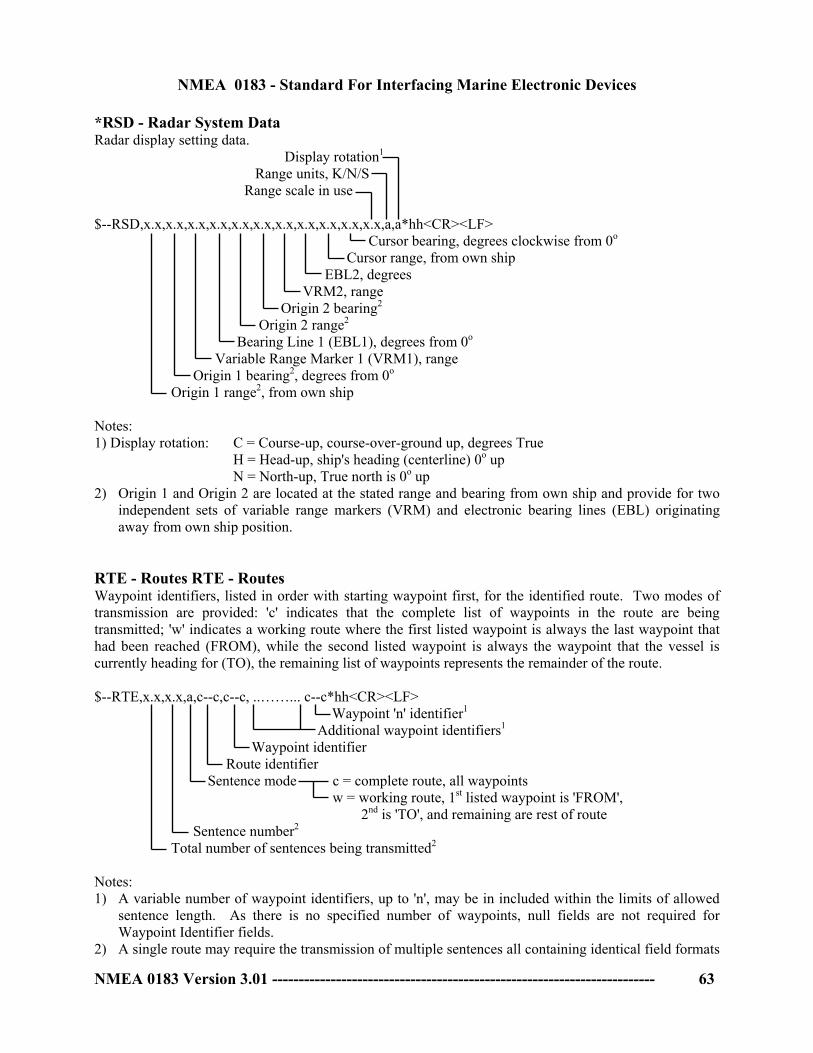
NMEA 0183 - Standard For Interfacing Marine Electronic Devices
*RSD - Radar System Data Radar display setting data. Display rotation1
Range units, K/N/S Range scale in use $--RSD,x.x,x.x,x.x,x.x,x.x,x.x,x.x,x.x,x.x,x.x,x.x,a,a*hh<CR><LF> Cursor bearing, degrees clockwise from 0o Cursor range, from own ship EBL2, degrees VRM2, range Origin 2 bearing2
Origin 2 range2
Bearing Line 1 (EBL1), degrees from 0o Variable Range Marker 1 (VRM1), range Origin 1 bearing2, degrees from 0o Origin 1 range2, from own ship
NMEA 0183 Version 3.01 ------------------------------------------------------------------------ 63
Notes: 1) Display rotation: C = Course-up, course-over-ground up, degrees True
H = Head-up, ship's heading (centerline) 0o up N = North-up, True north is 0o up
2) Origin 1 and Origin 2 are located at the stated range and bearing from own ship and provide for two independent sets of variable range markers (VRM) and electronic bearing lines (EBL) originating away from own ship position.
RTE - Routes RTE - Routes Waypoint identifiers, listed in order with starting waypoint first, for the identified route. Two modes of transmission are provided: 'c' indicates that the complete list of waypoints in the route are being transmitted; 'w' indicates a working route where the first listed waypoint is always the last waypoint that had been reached (FROM), while the second listed waypoint is always the waypoint that the vessel is currently heading for (TO), the remaining list of waypoints represents the remainder of the route. $--RTE,x.x,x.x,a,c--c,c--c, ..……... c--c*hh<CR><LF> Waypoint 'n' identifier1 Additional waypoint identifiers1
Waypoint identifier Route identifier Sentence mode c = complete route, all waypoints w = working route, 1st listed waypoint is 'FROM', 2nd is 'TO', and remaining are rest of route Sentence number2 Total number of sentences being transmitted2
Notes: 1) A variable number of waypoint identifiers, up to 'n', may be in included within the limits of allowed
sentence length. As there is no specified number of waypoints, null fields are not required for Waypoint Identifier fields.
2) A single route may require the transmission of multiple sentences all containing identical field formats

NMEA 0183 - Standard For Interfacing Marine Electronic Devices
when sending a complete message. The first field specifies the total number of sentences, minimum value = 1. The second field identifies the order of this sentence (sentence number), minimum value = 1. For efficiency it is recommended that null fields be used in the additional sentences when the data is unchanged from the first sentence.
*SFI - Scanning Frequency Information This sentence is used to set frequencies and mode of operation for scanning purposes and to acknowledge setting commands. Scanning frequencies are listed in order of scanning. Note: For DSC distress and safety watchkeeping only 6 channels shall be scanned in the same scanning sequence. To indicate a frequency set at the scanning receiver use FSI sentence. $--SFI,x.x,x.x,xxxxxx,c, ..………..... xxxxxx,c*hh<CR><LF> 6th frequency, mode3
2nd - 5th frequency, mode3 Mode of operation1
1st frequency or ITU channel2
Sentence number4
Total number of sentences being transmitted4
Notes: 1) Mode of operation: d = F3E/G3E simplex, telephone x = A1A Morse, tape recorder e = F3E/G3E duplex, telephone { = A1A Morse, Morse key/head set m = J3E, telephone | = F1C/F2C/F3C, FAX-machine o = H3E, telephone null for no information q = F1B/J2B FEC NBDP, telex/teleprinter s = F1B/J2B ARQ NBDP, telex/teleprinter t = F1B/J2B receive only, teleprinter/DSC w = F1B/J2B, teleprinter/DSC 2) Frequencies to be in 100 Hz increments.
MF/HF telephone channels to have first digit 3 followed by ITU channel numbers with leading zeros as required. MF/HF teletype channels to have first digit 4; the second and third digit frequency bands; and the fourth to sixth digits ITU channel numbers; each with leading zeros as required. VHF channels to have the first digit 9 followed by zero. The next number is “1” indicating the ship station’s transmit frequency is being used as a simplex channel frequency, or “2” indicating the coast station’s transmit frequency is being used as a simplex channel frequency, “0” otherwise. The remaining three numbers are the VHF channel numbers with leading zeros as required.
3) A variable number of frequency-mode pair fields are allowed up to a maximum of six pairs. Null fields are not required for unused pairs when less than six pairs are transmitted.
4) Scanning frequency information may require the transmission of multiple sentences when sending a complete message. The first field specifies the total number of sentences, minimum value = 1. The second field identifies the order of this sentence (sentence number), minimum value = 1.
NMEA 0183 Version 3.01 ------------------------------------------------------------------------ 64

NMEA 0183 - Standard For Interfacing Marine Electronic Devices
SSD - UAIS Ship Static Data This sentence is used to enter static parameters into a shipboard AIS unit. The parameters in this sentence support a number of the ITU-R M.1371 messages. $--SSD,c--c,c--c,xxx,xxx,xx,xx,c,aa*hh<CR><LF>
Source Identifier 5DTE indicator flag 4
Pos. ref. point distance, "D," from starboard beam 3, 0 to 63 Meters
Pos. ref. point distance, "C," from port beam 3, 0 to 63 Meters Pos. ref. point distance, "B," from stern 3, 0 to 511 Meters Pos. ref. point distance, "A," from bow 3, 0 to 511 meters Ship's Name 2, 1 to 20 characters
Ship's Call Sign 1, 1 to 7 characters
NMEA 0183 Version 3.01 ------------------------------------------------------------------------ 65
Notes: 1) Ship call sign. A null field indicates that the previously entered call sign is unchanged. The string of
characters "@@@@@@@" are used to indicate that the call sign is not available. 2) The characters that can be used in the name are listed in the ITU-R M.1371 6 bit ASCII Table. Some
of these characters are reserved characters within this standard. They must be represented using the "^" method (see section 5.1.3). A null field indicates that the previously entered name is unchanged. The string of characters "@@@@@@@@@@@@@@@@@@@@" are used to indicate that the ship's name is not available.
3) These are the four dimensions from the bow, stern, port beam, and starboard beam to the horizontal reference point on the ship for which the current "position reports" are valid. The sum of A + B is the length of the ship in meters, and the sum of C + D is the width of the ship in meters. Refer to the ITU-R M.1371 Message 5, "Reference Point for reported position and Dimensions of Ship." If the reference point of "reported position" is not available, but the dimensions of the ship are available: A = C = 0 and B > 0 and D > 0. If neither the reference point for the reported position nor the dimensions of the ship are available: A = B = C = D = 0 (default). Use of a null field for A, B, C, and/or D indicates that the previously entered dimension for that parameter is unchanged. In many cases, the ship's reference point for "reported position" will be the location of the positioning antenna.
4) The DTE indicator is an abbreviation for Data Terminal Equipment indicator. The purpose of the DTE indicator is to inform distant receiving applications that, if set to "available," the transmitting station conforms, at least, to the minimum keyboard and display requirements. The DTE indicator is only used as information provided to the application layer - indicating that the transmitting station is available for communications. On the transmitting side, the DTE indicator may be set by an external application using this sentence. DTE indicator flag values are:
0 = Keyboard and display are a standard configuration, and communication is supported. 1 = Keyboard and display are either unknown or unable to support communication.
5) The Source Identifier contains the Talker ID of the equipment at this location. STN - Multiple Data ID This sentence is transmitted before each individual sentence where there is a need for the Listener to determine the exact source of data in a system. Examples might include dual-frequency depthsounding equipment or equipment that integrates data from a number of sources and produces a single output. $--STN,xx*hh<CR><LF> Talker ID number, 00 to 99

NMEA 0183 - Standard For Interfacing Marine Electronic Devices
TLB - Target Label Common target labels for tracked targets. This sentence is used to specify labels for tracked targets to a device that provides tracked target data (e.g., via the TTM – Tracked Target Message). This will allow all devices displaying tracked target data to use a common set of labels (e.g., targets reported by two radars and displayed on an ECDIS). $--TLB,x.x,c--c,x.x,c--c, … x.x,c--c*hh<CR><LF> Additional label pairs1
Label assigned to target ‘n’2
Target number ‘n’ reported by the device
NMEA 0183 Version 3.01 ------------------------------------------------------------------------ 66
Notes: 1. This sentence allows several target number/labels pairs to be sent in a single sentence, the maximum
sentence length limits the number of labels allowed in a sentence. 2. Null fields indicate that no common label is specified, not that a null label should be used. The intent
is to use a null field as a placeholder. A device that provides tracked target data should use its “local” label (usually the target number) unless it has received a TLB sentence specifying a common label.
TLL - Target Latitude and Longitude Target number, name, position and time tag for use in systems tracking targets. $--TLL,xx,llll.ll,a,yyyyy.yy,a,c--c,hhmmss.ss,a,a*hh <CR><LF> R = Reference target2, null otherwise Target status1 UTC of data Target name Target longitude, E/W Target latitude, N/S Target number, 00 to 99 Notes 1) Target status: L = Lost, tracked target has been lost
Q = Query, target in the process of acquisition T = Tracking
2) Reference Target: set to "R" if target is a reference used to determined own-ship position or velocity, null otherwise.
*TTM - Tracked Target Message Data associated with a tracked target relative to own ship's position.
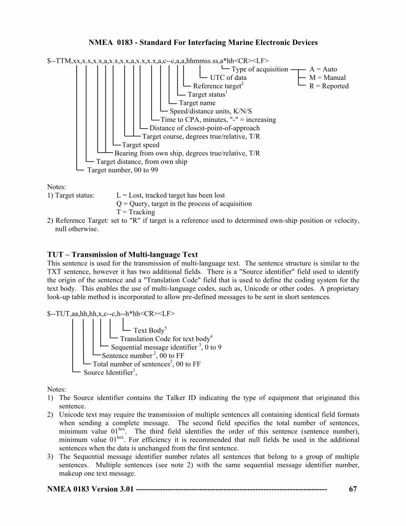
NMEA 0183 - Standard For Interfacing Marine Electronic Devices
$--TTM,xx,x.x,x.x,a,x.x,x.x,a,x.x,x.x,a,c--c,a,a,hhmmss.ss,a*hh<CR><LF> Type of acquisition A = Auto UTC of data M = Manual Reference target2 R = Reported Target status1 Target name Speed/distance units, K/N/S Time to CPA, minutes, "-" = increasing Distance of closest-point-of-approach Target course, degrees true/relative, T/R Target speed Bearing from own ship, degrees true/relative, T/R Target distance, from own ship Target number, 00 to 99
NMEA 0183 Version 3.01 ------------------------------------------------------------------------ 67
Notes: 1) Target status: L = Lost, tracked target has been lost
Q = Query, target in the process of acquisition T = Tracking
2) Reference Target: set to "R" if target is a reference used to determined own-ship position or velocity, null otherwise.
TUT – Transmission of Multi-language Text This sentence is used for the transmission of multi-language text. The sentence structure is similar to the TXT sentence, however it has two additional fields. There is a "Source identifier" field used to identify the origin of the sentence and a "Translation Code" field that is used to define the coding system for the text body. This enables the use of multi-language codes, such as, Unicode or other codes. A proprietary look-up table method is incorporated to allow pre-defined messages to be sent in short sentences. $--TUT,aa,hh,hh,x,c--c,h--h*hh<CR><LF>
Text Body5
Translation Code for text body4
Sequential message identifier 3, 0 to 9 Sentence number 2, 00 to FF Total number of sentences2, 00 to FF Source Identifier1, Notes: 1) The Source identifier contains the Talker ID indicating the type of equipment that originated this
sentence. 2) Unicode text may require the transmission of multiple sentences all containing identical field formats
when sending a complete message. The second field specifies the total number of sentences, minimum value 01hex. The third field identifies the order of this sentence (sentence number), minimum value 01hex. For efficiency it is recommended that null fields be used in the additional sentences when the data is unchanged from the first sentence.
3) The Sequential message identifier number relates all sentences that belong to a group of multiple sentences. Multiple sentences (see note 2) with the same sequential message identifier number, makeup one text message.

NMEA 0183 - Standard For Interfacing Marine Electronic Devices
4) The translation code identifies the Hex character coding method used in the text body field and determines the maximum number of Hex character positions available in the "text body" field.
U = Unicode (ISO 10646-1), 56 Hex character positions in the text body. A = ASCII (Subset of ISO 8859-1), 56 Hex character positions in the text body. 1-16 = The specific part number of the ISO 8859 standard, a value of 3 would refer to ISO 8859-3. P<aaa> = Proprietary (user defined), 53 Hex character positions in the text body. This field consists of the letter "P" directly followed by the three letter Manufacturer's Mnemonic Code. An example might be "PXYZ", if the XYZ company's equipment produced a TUT sentence with a proprietary translation code.
5) The Text Body consists either 56 or 53 Hex character positions, depending on the "translation code field". The number and type of characters and code delimiters if needed, up to the maximum permitted sentence length, are as follows:
U => Up to fourteen 16-bit Unicode characters including code delimiters. Each Unicode
character is represented by 4 Hex character codes. The letter "A" would be represented by 0041hex, while the "Katakana letter A" would be represented by 30A2hex.
A or 1-16 => Up to twenty-eight 8-bit ASCII characters including code delimiters. Each ASCII character is represented by 2 Hex character codes. The letter "A" would be represented by 41hex, while the Latin capital letter thorn "Þ" would be represented by DEhex. The "Katakana letter A" cannot be represented by 2 Hex character codes.
P<aaa> => Up to fifty-three 4-bit user-defined characters including code delimiters. These are intended to be used as an index or entry into a user defined (proprietary) look-up table. Each character is represented by 1 or more Hex character codes.
Example scenario containing the Proprietary and Unicode translation codes: A depth sounder sends a warning of "Shallow Water!" to an Integrated Navigation System using a Proprietary translation code. The Integrated Navigation System sends a Unicode Text Message to a remote display in the local language of Kanji.
$SDTUT,SD,01,01,1,PXYZ,02*6D<CR><LF> The integrated navigation system, upon receiving this sentence would look within in it's own table for the Unicode Text contents referenced by the value 02. The text being reported in this TUT example is "Shallow Water!". Note that there is no constraint on how many Hex characters are used to represent the look-up value. It could be represented in the field as 2 or 02 or 002 or 0002, as long as the sender and receiver of this know how to interpret this proprietary text body. The integrated navigation system could then generate and send the following sentence using the Unicode Translation code to a remote display device in the local language desired, Kanji in this example. The Kanji equivalent of "Shallow Water!" is " ", and is represented according to Unicode as the Hex codes of 6D45 702C 5371 967A.
$INTUT,SD,01,01,1,U,6D45702C5371967A*5D<CR><LF> The same text "Shallow Water!" could have been generated by the integrated navigation system using the ASCII translation code as shown below.
$INTUT,SD,01,01,1,A,5368616C6C6F7720576174657221*4B<CR><LF>
NMEA 0183 Version 3.01 ------------------------------------------------------------------------ 68

NMEA 0183 - Standard For Interfacing Marine Electronic Devices
TXT - Text Transmission For the transmission of short text messages, longer text messages may be transmitted by using multiple sentences. $--TXT,xx,xx,xx,c--c*hh<CR><LF> Text message3
Text identifier2
Sentence number1, 01 to 99 Total number of sentences1, 01 to 99
NMEA 0183 Version 3.01 ------------------------------------------------------------------------ 69
Notes: 1) Text messages may consist of the transmission of multiple sentences all containing identical field
formats when sending a complete message. The first field specifies the total number of sentences, minimum value 1. The second field identifies the order of this sentence (sentence number), minimum value 1. For efficiency it is recommended that null fields be used in the additional sentences when the data is unchanged from the first sentence.
2) The text identifier is a number, 01 to 99, used to identify different text messages. 3) ASCII characters, and code delimiters if needed, up to the maximum permitted sentence length (i.e.,
up to 61 characters including any code delimiters). Example: A GPS receiver sends a text alarm message (message ID 25, DR MODE - ANTENNA
FAULT!) upon reverting to dead-reckoning mode due to an antenna fault. (note the use of “^21” to indicate “!”, see section 5.1.3).
$GPTXT,01,01,25,DR MODE - ANTENNA FAULT^21*38<CR><LF> *VBW - Dual Ground/Water Speed Water referenced and ground referenced speed data. $--VBW,x.x,x.x,A,x.x,x.x,A,x.x,A,x.x,A*hh<CR><LF> Status, stern ground speed A = Data valid V = Invalid Stern transverse ground speed1, knots Status, stern water speed, A = Data valid Stern transverse water speed1, knots
Status, Ground speed, A = Data valid Transverse ground speed1, knots Longitudinal ground speed 1, knots Status: Water speed, A = Data valid Transverse water speed1, knots Longitudinal water speed1, knots
Notes: 1) Transverse speed: "-" = port, Longitudinal speed: "-" = astern VDR - Set and Drift

NMEA 0183 - Standard For Interfacing Marine Electronic Devices
The direction towards which a current flows (Set) and speed (Drift) of a current. $--VDR,x.x,T,x.x,M,x.x,N*hh<CR><LF> Current speed, knots Direction, degrees Magnetic Direction, degrees True
NMEA 0183 Version 3.01 ------------------------------------------------------------------------ 70
VHW - Water Speed and Heading The compass heading to which the vessel points and the speed of the vessel relative to the water. $--VHW,x.x,T,x.x,M,x.x,N,x.x,K*hh<CR><LF> Speed, km/hr Speed, knots Heading, degrees Magnetic Heading, degrees True VLW - Dual Ground/Water Distance The distance traveled, relative to the water and over the ground. $--VLW,x.x,N,x.x,N,x.x,N,x.x,N*hh<CR><LF> Ground distance since reset, nautical miles Total cumulative ground distance, nautical miles Water distance since reset, nautical miles Total cumulative water distance, nautical miles VPW - Speed - Measured Parallel to Wind The component of the vessel's velocity vector parallel to the direction of the true wind direction. Sometimes called "speed made good to windward" or "velocity made good to windward". $--VPW,x.x,N,x.x,M*hh<CR><LF> Speed, meters/second, "-" = downwind Speed, knots, "-" = downwind VSD - UAIS Voyage Static Data This sentence is used to enter information about a ship's transit that remains relatively static during the voyage. However, the information often changes from voyage to voyage. The parameters in this sentence support a number of the ITU-R M.1371 messages. $--VSD,x.x,x.x,x.x,c--c,hhmmss.ss,xx,xx,x.x,x.x*hh<CR><LF>
Regional application flags 8, 0 to 15
Navigational status 7, 0 to 15
Estimated month of arrival at destination 6, 00 to 12 (UTC) Estimated day of arrival at destination 6, 00 to 31 (UTC)
Estimated UTC of arrival at destination 5
Destination 4, 1-20 characters
Persons on-board 3, 0 to 8191
Maximum present static draught 2, 0 to 25.5 Meters
Type of ship and cargo category 1, 0 to 255

NMEA 0183 - Standard For Interfacing Marine Electronic Devices
NMEA 0183 Version 3.01 ------------------------------------------------------------------------ 71
Notes: 1) Type of ship and cargo category are defined under Message 5 of ITU-R M.1371. The description of
ship and cargo are indicated by a number. A null field indicates that this is unchanged. 2) The Draught is reported in units of Meters. Valid range is 0 to 25.5. The value 0 = not available, and the value 25.5 indicates that the draught is 25.5 meters or more. A null field indicates that this is unchanged.
3) Current number of persons on-board, including crew. Valid range is 0 to 8191. The value 0 = not available, and the value 8191 = 8191 or more people. A null field indicates that this is unchanged.
4) The characters that can be used in the Destination are listed in the ITU-R M.1371 6 bit ASCII Table. Some of these characters are reserved characters within this standard. They must be represented using the "^" method (see section 5.1.3). A null field indicates that the previously entered Destination is unchanged. The string of characters "@@@@@@@@@@@@@@@@@@@@" are used to indicate that the ship's Destination is not available.
5) If the hour of arrival is not available, "hh" shall be set to 24. If the minute of arrival is not available, "mm" shall be set to 60. The seconds portion "ss.ss" of the field may be set to "00" as the AIS unit only broadcasts hours and minutes. A null field indicates that this is unchanged.
6) The day and month of arrival are in UTC. The field is a fixed two-digit number requiring leading zeros. If the day of arrival is not available, "00" shall be the number for day. If the month of arrival is not available, "00" shall be the number for the month. A null field indicates that this is unchanged.
7) The Navigational status is indicated using the following values, a null field indicates the status is unchanged (ref. ITU-R M.1371, Message 1, Navigational status parameter):
0 = under way using engine 4 = constrained by draught 9 = reserved for High Speed Craft (HSC)
1 = at anchor 5 = moored 10 = reserved for Wing In Ground (WIG)
2 = not under command 6 = aground 11 to 14 = reserved for future use
7 = engaged in fishing 3 = restricted maneuverability 8 = under way sailing
15 = default
8) Definition of values 1 to 15 provided by a competent regional authority. Value shall be set to zero (0), if not used for any regional application. Regional applications shall not use zero. A null field indicates that this is unchanged (ref. ITU-R M.1371, Message 1, Reserved for regional applications parameter).
VTG - Course Over Ground and Ground Speed The actual course and speed relative to the ground. $--VTG,x.x,T,x.x,M,x.x,N,x.x,K,a*hh<CR><LF> Mode Indicator1
Speed over ground, km/hr Speed over ground, knots Course over ground, degrees Magnetic Course over ground, degrees True Notes: 1) Positioning system Mode Indicator: A = Autonomous mode
D = Differential mode E = Estimated (dead reckoning) mode
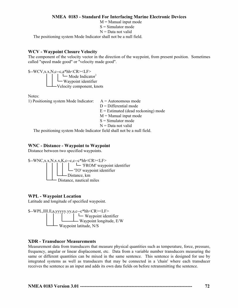
NMEA 0183 - Standard For Interfacing Marine Electronic Devices
NMEA 0183 Version 3.01 ------------------------------------------------------------------------ 72
M = Manual input mode S = Simulator mode N = Data not valid
The positioning system Mode Indicator shall not be a null field. WCV - Waypoint Closure Velocity The component of the velocity vector in the direction of the waypoint, from present position. Sometimes called "speed made good" or "velocity made good". $--WCV,x.x,N,c--c,a*hh<CR><LF> Mode Indicator1
Waypoint identifier Velocity component, knots Notes: 1) Positioning system Mode Indicator: A = Autonomous mode
D = Differential mode E = Estimated (dead reckoning) mode M = Manual input mode S = Simulator mode N = Data not valid
The positioning system Mode Indicator field shall not be a null field. WNC - Distance - Waypoint to Waypoint Distance between two specified waypoints. $--WNC,x.x,N,x.x,K,c--c,c--c*hh<CR><LF> 'FROM' waypoint identifier 'TO' waypoint identifier Distance, km Distance, nautical miles WPL - Waypoint Location Latitude and longitude of specified waypoint. $--WPL,llll.ll,a,yyyyy.yy,a,c--c*hh<CR><LF> Waypoint identifier Waypoint longitude, E/W Waypoint latitude, N/S XDR - Transducer Measurements Measurement data from transducers that measure physical quantities such as temperature, force, pressure, frequency, angular or linear displacement, etc. Data from a variable number transducers measuring the same or different quantities can be mixed in the same sentence. This sentence is designed for use by integrated systems as well as transducers that may be connected in a 'chain' where each transducer receives the sentence as an input and adds its own data fields on before retransmitting the sentence.

NMEA 0183 - Standard For Interfacing Marine Electronic Devices
NMEA 0183 Version 3.01 ------------------------------------------------------------------------ 73
$--XDR,a,x.x,a,c--c,...…………...a,x.x,a,c--c*hh<CR><LF> Transducer 'n'1 Data for variable # of transducers Transducer #1 ID Units of measure, Transducer #12
Measurement data, Transducer #1 Transducer type, Transducer #12
Notes: 1) Sets of the four fields 'Type-Data-Units-ID' are allowed for an undefined number of transducers.
Up to 'n' transducers may be included within the limits of allowed sentence length, null fields are not required except where portions of the 'Type-Data-Units-ID' combination are not available.
2) Allowed transducer types and their units of measure are: Transducer Type Field Units Field Comments
temperature C C = degrees Celsius angular displacement A D = degrees "-" = anti-clockwise linear displacement D M = meters "-" = compression frequency F H = Hertz force N N = Newton "-" = compression pressure P B = Bars, P = Pascal "-" = vacuum flow rate R l = liters/second tachometer T R = RPM humidity H P = Percent volume V M = cubic meters generic G none (null) x.x = variable data current I A = Amperes voltage U V = Volts switch or valve S none (null) 1 = ON/ CLOSED, 0 = OFF/ OPEN salinity L S = ppt ppt = parts per thousand
XTE - Cross-Track Error, Measured Magnitude of the position error perpendicular to the intended track line and the direction to steer to return to the intended track. $--XTE,A,A,x.x,a,N,a*hh<CR><LF> Mode Indicator1,2
Units, nautical miles Direction to steer, L/R Magnitude of Cross-Track-Error Status2 A = Data valid V = Loran-C Cycle Lock warning flag Status2 A = Data valid V = Loran-C Blink or SNR warning V = general warning flag for other navigation systems when a reliable fix is not available Notes: 1) Positioning system Mode Indicator: A = Autonomous mode
D = Differential mode E = Estimated (dead reckoning) mode M = Manual input mode S = Simulator mode

NMEA 0183 - Standard For Interfacing Marine Electronic Devices
NMEA 0183 Version 3.01 ------------------------------------------------------------------------ 74
N = Data not valid 2) The positioning system Mode Indicator field supplements the positioning system Status fields, the
Status fields shall be set to V = Invalid for all values of Indicator mode except for A= Autonomous and D = Differential. The positioning system Mode Indicator and Status fields shall not be null fields.
XTR - Cross-Track Error - Dead Reckoning Magnitude of the dead reckoned position error perpendicular to the intended track line and the direction to steer to return to the intended track. $--XTR,x.x,a,N*hh<CR><LF> Units, nautical miles Direction to steer, L/R Magnitude of Cross-Track-Error ZDA - Time & Date UTC, day, month, year and local time zone. $--ZDA,hhmmss.ss,xx,xx,xxxx,xx,xx*hh<CR><LF> Local zone minutes1, 00 to +59 Local zone hours1, 00 to ±13 hrs Year Month, 01 to 12 UTC Day, 01 to 31 UTC Notes: 1) Local time zone is the magnitude of hours plus the magnitude of minutes added, with the sign of local
zone hours, to local time to obtain UTC. Local zone is generally negative for East longitudes with local exceptions near the International Date Line.
Example: At Chatham Is. (New Zealand) at 1230 (noon) local time on June 10, 1995 :
$GPZDA,234500,09,06,1995,-12,45*6C<CR><LF> In the Cook Islands at 1500 local time on June 10, 1995:
$GPZDA,013000,11,06,1995,10,30*4A<CR><LF> ZDL - Time and Distance to Variable Point Time and distance to a point that might be non-fixed. The point is generally not a specific geographic point but may vary continuously and is most often determined by calculation (the recommended turning or tacking point for sailing vessels, the wheel-over point for vessels making turns, a predicted collision point, etc.) $--ZDL,hhmmss.ss,x.x,a*hh<CR><LF> Type of point C = Collision T = Turning point R = Reference (general) W = Wheelover Distance to point, nautical miles Time to point, hh = 00 to 99 hours

NMEA 0183 - Standard For Interfacing Marine Electronic Devices
NMEA 0183 Version 3.01 ------------------------------------------------------------------------ 75
ZFO - UTC & Time from Origin Waypoint UTC and elapsed time from origin waypoint. $--ZFO,hhmmss.ss,hhmmss.ss,c--c*hh<CR><LF> Origin waypoint ID Elapsed time, hh = 00 to 99 UTC of observation ZTG - UTC & Time to Destination Waypoint UTC and predicted time-to-go to destination waypoint. $--ZTG,hhmmss.ss,hhmmss.ss,c--c*hh<CR><LF> Destination waypoint ID Time-to-go, hh = 00 to 99 UTC of observation 6.4 Approved Encapsulation Sentences General format of printed sentence information: *{mnemonic} - {name} {definition paragraph} !--{sentence} {field descriptions} Start of sentence and Talker ID *Designated by IEC for use with IMO maritime electronic devices as required by IMO in the
SOLAS convention (1974 as amended). Encapsulation Formatters ABM - UAIS Addressed binary and safety related message. This sentence supports ITU-R M.1371 messages 6 and 12 and provides an external application with a means to exchange data via an AIS transponder. Data is defined by the application only, not the AIS unit. This sentence offers great flexibility for implementing system functions that use the transponder like a communications device. After receiving this sentence via the NMEA 0183 interface, the transponder initiates a VDL broadcast of either message 6 or 12. The AIS unit will make up to four broadcasts of the message. The actual number will depend on the reception of an acknowledgement from the addressed "destination" AIS unit. The success or failure of reception of this transmission by the addressed AIS unit is confirmed through the use of the "Addressed Binary and safety related message Acknowledgement" ABK sentence formatter, and the processes that supports the generation of an ABK sentence.

NMEA 0183 - Standard For Interfacing Marine Electronic Devices
NMEA 0183 Version 3.01 ------------------------------------------------------------------------ 76
!--ABM,x,x,x,xxxxxxxxx,x,xx,s--s,x*hh<CR><LF> Number of fill-bits 6, 0 to 5
Encapsulated data5
ITU-R M.1371 message Id (6 or 12) AIS channel for broadcast of the radio message 4
The MMSI of the destination AIS unit for the ITU-R M.1371 message 6 or 12 3
Sequential message identifier 2, 0 to 3 Sentence number 1, 1 to 9
Total number of sentences needed to transfer the message 1, 1 to 9 Notes: 1) The total number of sentences required to transfer the binary message data to the AIS unit. The first
field specifies the total number of sentences used for a message, minimum value 1. The second field identifies the order of this sentence in the message, minimum value 1. All sentences contain the same number of fields. Successive sentences may use null fields for fields that have not changed, such as fields 4, 5, and 6.
2) This sequential message identifier serves two purposes. It meets the requirements as stated in Section 5.3.3 of this standard, and it is the sequence number utilized by ITU-R M.1371 in message types 6 and 12. The range of this field is restricted by ITU-R M1371 to 0 - 3. The sequential message identifier value may be reused after the AIS unit provides the "ABK" acknowledgement for this number. See the ABK sentence .
3) The MMSI of the AIS unit that is the destination of the message. 4) The AIS channel that shall be used for the broadcast: 0 = no broadcast channel preference, 1 =
Broadcast on AIS channel A, 2 = Broadcast on AIS channel B, 3 = Broadcast message on both AIS channels A and B.
5) This is the content of the "binary data" parameter for ITU-R M.1371 message 6, or the "Safety related Text" parameter for message 12. The first sentence may contain up to 48 valid Six Bit codes (288 bits). Following sentences may contain up to 60 valid Six Bit codes (360 bits), if fields 4, 5, and 6 are unchanged from the first sentence and set to null. The actual number of valid characters must be such that the total number of characters in a sentence does not exceed the "82-character" limit.
6) This cannot be a null field. See Section 5.3.3.1 "Fill Bits field" description. BBM - UAIS Broadcast Binary Message. This sentence supports generation of ITU-R M.1371 binary messages 8 and 14. This provides the application with a means to broadcast data, as defined by the application only. Data is defined by the application only not the AIS. This sentence offers great flexibility for implementing system functions that use the transponder like a digital broadcast device. After receiving this sentence via the NMEA 0183 interface, the transponder initiates a VHF broadcast of either message 8 or 14 within four seconds. See the ABK sentence for acknowledgement of the BBM. !--BBM,x,x,x,x,xx,s--s,x*hh<CR><LF> Number of fill-bits 5, 0 to 5 Encapsulated data 4 ITU-R M.1371 message Id (8 or 14) AIS channel for broadcast of the radio message 3
Sequential Message identifier 2, 0 to 9 Sentence number 1, 1 to 9
Total number of sentences needed to transfer the message 1, 1 to 9 Notes:

NMEA 0183 - Standard For Interfacing Marine Electronic Devices
NMEA 0183 Version 3.01 ------------------------------------------------------------------------ 77
1) The total number of sentences required to transfer the contents of the binary message to the AIS unit. The first field specifies the total number of sentences used for a message, minimum value 1. The second field identifies the order of this sentence in the message, minimum value 1. All sentences contain the same number of fields. Successive sentences may use null fields for fields that have not changed, such as fields 4 and 5.
2) The Sequential message identifier provides a message identification number from 0 to 9 that is sequentially assigned and is incremented for each new multi-sentence message. The count resets to 0 after 9 is used. For a message requiring multiple sentences, each sentence of the message contains the same sequential message identification number. It is used to identify the sentences containing portions of the same message. This allows for the possibility that other sentences might be interleaved with the message sentences that, taken collectively, contain a single message. This value is used by the ABK sentence to acknowledge a specific BBM sentence.
3) The AIS channel that shall be used for the broadcast: 0 = no broadcast channel preference, 1 = Broadcast on AIS channel A, 2 = Broadcast on AIS channel B, 3 = Broadcast the message on both AIS channels A and B.
4) This is the content of the "binary data" parameter for ITU-R M.1371 messages 8, 19, and 21, or the "Safety related Text" parameter for message 14. The first sentence may contain up to 58 valid Six Bit codes (348 bits). Following sentences may contain up to 60 valid Six Bit codes (360 bits), if fields 4 and 5 are unchanged from the first sentence and set to null. The actual number of characters must be such that the total number of characters in a sentence does not exceed the "82-character" limit.
5) This cannot be a null field. See Section 5.3.3.1 "Fill Bits field" description. VDM - UAIS VHF Data-link Message This sentence is used to transfer the entire contents of a received AIS message packet, as defined in ITU-R M.1371 and as received on the VHF Data Link (VDL), using the "Six Bit" field type. The structure provides for the transfer of long binary messages by using multiple sentences. !--VDM,x,x,x,a,s--s,x*hh<CR><LF>
Number of fill-bits 5, 0 to 5 Encapsulated ITU-R M.1371 radio message 4 AIS Channel 3 Sequential message identifier 2, 0 to 9
Sentence number 1, 1 to 9 Total number of sentences needed to transfer the message 1, 1 to 9 Notes: 1) The length of an ITU-R M.1371 message may require the transmission of multiple sentences. The
first field specifies the total number of sentences used for a message, minimum value 1. The second field identifies the order of this sentence in the message, minimum value 1. These cannot be null fields.
2) The Sequential message identifier provides a message identification number from 0 to 9 that is sequentially assigned and is incremented for each new multi-sentence message. The count resets to 0 after 9 is used. For a message requiring multiple sentences, each sentence of the message contains the same sequential message identification number. It is used to identify the sentences containing portions of the same message. This allows for the possibility that other sentences might be interleaved with the message sentences that, taken collectively, contain a single message. This shall be a null field for messages that fit into one sentence.
3) The AIS channel is indicated as either A or B. This channel indication is relative to the operating conditions of the transponder when the packet is received. This shall be a null field when the channel identification is not provided. The frequencies for channels A and B are obtained by a query (See section 5.3.4 of this standard) of the AIS unit for an ACA sentence(s).

NMEA 0183 - Standard For Interfacing Marine Electronic Devices
NMEA 0183 Version 3.01 ------------------------------------------------------------------------ 78
4) This field supports a maximum of 62 valid characters for messages transferred using multiple sentences, and 63 valid characters for messages using a single sentence.
5) This cannot be a null field. See Section 5.3.3.1 "Fill Bits field" description. VDO - UAIS VHF Data-link Own-vessel report This sentence is used to transfer the entire contents of an AIS unit's broadcast message packet, as defined in ITU-R M.1371 and as sent out by the AIS unit over the VHF Data Link (VDL), using the "Six Bit" field type. The structure provides for the transfer of long binary messages by using multiple sentences. The sentence uses the same structure as the VDM sentence formatter. !--VDO,x,x,x,a,s--s,x*hh<CR><LF> Number of fill-bits 5, (0 to 5) Encapsulated ITU-R M.1371 radio message 4 AIS Channel 3 Sequential message identifier 2, 0 to 9 Sentence number 1, 1 to 9 Total number of sentences needed to transfer the message 1, 1 to 9 Notes: Refer to VDM sentence notes. 7. Applications 7.1 Example Parametric Sentences These examples are intended as samples of correctly constructed sentences. They are representative samples only and show part of the wide range of legal variations possible with sentences. They should not necessarily be used as templates for sentences. 7.1.1 Example #1, Loran C LAT/LON This example gives present position in Latitude-Longitude, as determined by Loran C. The 3-character mnemonic in the address, GLL, indicates that the data is present position in Latitude-Longitude. The time (UTC) of the position fix is 09 hours, 13 minutes and 42 seconds. Decimal seconds are not available and the decimal point is optionally omitted. There are no warning flags set in the navigation receiver as indicated by Status = 'A' and Mode Indicator = “A”. $LCGLL,4728.31,N,12254.25,W,091342,A,A*4C<CR><LF> Sentence Terminator Checksum 4C HEX Mode Indicator: A = Autonomous mode Receiver status: no warnings Time of position fix Units Designator (West) Long. 122 Degrees, 54.25 Minutes Units Designator (North) Lat. 47 Degrees, 28.31 Minutes Address LC = Loran C GLL = Present Position Start of Sentence

NMEA 0183 - Standard For Interfacing Marine Electronic Devices
NMEA 0183 Version 3.01 ------------------------------------------------------------------------ 79
7.1.2 Example #2, Loran C Arrival Alarm This example illustrates Arrival Alarm data. The mnemonic code for Arrival Alarm is AAM. In this case the address Field is "LCAAM" for Loran C Arrival Alarm. The first data field shows "V" indicating the radius of the arrival circle HAS NOT been entered, the second data field is "A" showing that the perpendicular to the course line, at the destination, HAS been crossed. The third and fourth fields show the radius and units of the destination waypoint arrival circle ".15,N" for 0.15 nautical miles. Data field five is the Waypoint Identifier field of valid characters. $LCAAM,V,A,.15,N,CHAT-N6*56<CR><LF> Sentence Terminator Checksum 56HEX Identifier for waypoint "CHAT-N6" Units of arrival circle, nautical miles Radius of arrival circle, .15 Status: perpendicular has been crossed Status: arrival circle has not been entered Address LC = Loran C AAM = Arrival Start of sentence 7.1.3 Example #3 - Proprietary Sentence A proprietary sentence has the following general format: 79 character Sentence or less $Paaa--------------------------------------------------*hh<CR><LF> End of Sentence Checksum data, 72 character max. 3 character manufacturer's mnemonic code Proprietary sentence identifier Start of sentence A specific example will have little meaning to someone other than the particular manufacturer that designed the sentence: $PSRDA003[470738][1224523]???RST47,3809,A004*47<CR><LF> End of Sentence Checksum 47HEX any series of valid (non-reserved) characters of manufacturer’s choice Unique manufacturer's assigned code Proprietary sentence identifier Start of sentence 7.1.4 Example #4 - RMA Examples The following group of sentences show a typical progression of output data as a Loran C receiver acquires stations: a) $LCRMA,V,,,,,14162.8,,,,,,N*6F<CR><LF>

NMEA 0183 - Standard For Interfacing Marine Electronic Devices
NMEA 0183 Version 3.01 ------------------------------------------------------------------------ 80
Data invalid, only one TD acquired. Fields where data is not yet available are null fields. b) $LCRMA,V,,,,,14172.3,26026.7,,,,,N*4C<CR><LF> Two TDs acquired but not settled, data invalid. c) $LCRMA,A,,,,,14182.3,26026.7,,,,,A*5B<CR><LF>
Data valid, two TDs cycled but Lat/Lon not yet calculated. d) $LCRMA,A,4226.26,N,07125.89,W,14182.3,26026.7,8.5,275.,14.0,W,A*05<CR><LF>
Normal operation. e) $LCRMA,V,4226.26,N,07125.89,W,14182.3,26026.7,8.5,275.,14.0,W,N*1D<CR><LF>
Data invalid, potential Loran problem f) $LCRMA,A,4226.265,N,07125.890,W,14172.33,26026.71,8.53,275.,14.0,W,D*3B<CR><LF>
Loran operating in high-resolution mode. 7.1.5 Example #5 - FSI Examples The following sentences show typical applications for remote control of radiotelephones: a) $CTFSI,020230,026140,m,0*14<CR><LF>
Set transmitter 2023 kHz, receiver 2614 kHz, mode J3E, telephone, standby. b) $CTFSI,020230,026140,m,5*11<CR><LF>
MF/HF radiotelephone set transmit 2023 kHz, receive 2614 kHz, mode J3E, telephone, medium power.
c) $CTFSI,,021820,o,*2D<CR><LF>
Set receiver 2182 kHz, mode H3E, telephone. d) $CDFSI,900016,,d,9*08<CR><LF>
Set VHF transmit and receive channel 16, F3E/G3E, simplex, telephone, high power. e) $CTFSI,300821,,m,9*17<CR><LF>
Set MF/HF radiotelephone to telephone channel 821 e.g. transmit 8255 kHz, receive 8779 kHz, mode J3E, telephone, high power.
f) $CTFSI,404001,,w,5*08<CR><LF>
Set MF/HF radiotelephone to teletype channel 1 in 4 MHz band e.g. transmit 4172.5 kHz, receive 4210.5 kHz, mode F1B/J2B, teleprinter, medium power.
g) $CTFSI,416193,,s,0*00<CR><LF>
MF/HF radiotelephone tuned to teletype channel 193 in 16 MHz band e.g. transmitter 16 784.5 kHz, receiver 16 902.5 kHz, mode F1B/J2E ARQ, TELEX/teleprinter, standby.
h) $CTFSI,041620,043020,|,9*0A<CR><LF>
Set MF/HF radiotelephone transmit 4162 kHz, receive 4302 kHz, mode F1C/F2C/F3C, FAX-machine, high power.
i) $CXFSI,,021875,t,*3A<CR><LF>
Scanning receiver set 2187.5 kHz, mode F1B/J2B, receive only, teleprinter/DSC.

NMEA 0183 - Standard For Interfacing Marine Electronic Devices
NMEA 0183 Version 3.01 ------------------------------------------------------------------------ 81
7.1.6 Example #6 - MSK/MSS Examples GPS receiver (GP) query sentences to a data receiver (CR): a) request for configuration information: $GPCRQ,MSK*2E<CR><LF>
reply could be: $CRMSK,293.0,M,100,A,10,1*6F<CR><LF> b) request for signal strength, S/N ratio: $GPCRQ,MSS*36<CR><LF>
reply could be: $CRMSS,50,17,293.0,100,1*55<CR><LF> 7.2 Example Encapsulation Sentences These examples are intended as samples of correctly constructed encapsulation sentences. They are representative samples only and show part of the wide range of legal variations possible with sentences. They should not necessarily be used as templates for sentences. 7.2.1 Example #1, UAIS VHF Data-link Message VDM sentence Encapsulation Example
Introduction This standard supports the transport of encapsulated binary coded data. In general, the proper decoding and interpretation of encapsulated binary data will require access to information developed and maintained outside of this standard. This standard contains information that describes how the data should be coded, decoded, and structured. The specific meaning of the binary data is obtained from the referenced standards. What follows is a practical example of how encapsulated binary coded data might be translated into meaningful information. The example is drawn from the operation of universal Automatic Identification System (AIS) equipment built to the ITU-R M.1371 recommendations. The sample sentence that will be used in this example is:
!AIVDM,1,1,,1,1P000Oh1IT1svTP2r:43grwb05q4,0*01<CR><LF>
Number of "fill-bits" added to complete the last 6-bit character 5, (0 to 5)
Contents of the ITU-R M.1371 radio message using the 6-bit field type 4
AIS Channel 3 Sequential message identifier 2, (0 to 9) Sentence number 1, (1 to 9) Total number of sentences needed to transfer the message 1, (1 to 9) Also included with this example are:
A worksheet for decoding and interpreting and encapsulated field, Table 8 - A copy of Table 15 from ITU-R M.1371.

NMEA 0183 - Standard For Interfacing Marine Electronic Devices
NMEA 0183 Version 3.01 ------------------------------------------------------------------------ 82
Background Discussion - encapsulation coding Before diving into the decoding process, it is useful to understand the source of the binary bits encapsulated in this string. AIS is radio technology that broadcasts messages using channels in the marine VHF band. There are a number of messages that can be broadcast by an AIS unit. The bit-by-bit descriptions of the contents of these messages are documented in tables contained in the ITU-R M.1371 international standard for AIS. Table 8 contains copy of Table 15 from ITU-R M.1371 as a sample. This table identifies all of the information needed to convert the encapsulated binary bits into information. The table identifies the bits, gives them parametric names, and units. The bits listed in Table 8 are the Message Data portion of a larger packet of binary bits that are created and broadcast by an AIS unit. The sample VDM sentence shown above is an example of the output that would be created by every AIS unit that properly received a single AIS unit's broadcast. The following diagram, Figure 5, shows the message data portions of the "radio packet" that is created and broadcast by an AIS unit. Only the message data bits (those described in the tables - such as Table 8 are encapsulated in the string contained in the VDM sentence.
157 158 159 160 161 162 163 164 165 166 167 1681 2 3 4 5 6 7 8 9 10 11 12 13 14 15 16
? ? ? ? ? ? ? ? ? ? ? ? ? ? ? ? ? ? ? ? ? ? ? ? ? ? ? ?
Message Data (maximum of 168 bits for one-slot, maximum of 1008 bits for five-slot)..................
Figure 5 - UAIS Message Data bits encapsulated in VDM sentence. Assume, as an example, that the first 12 bits of the Message Data in Figure 1 (bits 1 to 12) are: 000001100000. These would be the first 12 bits coded into the VDM encapsulate string. The VDM sentence encapsulates data using the symbols of the "6-bit" Field Type. Each of the 64 possible combinations of one's and zero's that can make up a 6-bit string has been assigned a unique valid character. These assignments are listed in Table 7, Six-bit Binary Field Conversion Table. For example, the first 12 bits would be divided into 6-bit strings, that is: 000001 and 100000. Using Table 7, the binary string 000001 can be represented by a "1", and the binary string 100000 can be represented by a "P". The first two characters in the VDM sentence encapsulated string would then be "1P". Note that observing upper and lower case letters is important when using Table 7. The maximum number of Message Data bits that can be contained in an AIS radio message is 1008 bits. This number of bits requires 168 6-bit symbols. This quantity of characters is greater than can be accommodated by a single standard sentence. The encapsulation sentence structure has been designed to allow an encapsulation field to be broken into smaller strings that are transferred using multiple sentences. The important point to remember is that the encapsulation fields from a multiple sentence group, identified by the sequence number field and order by sentence number fields, be recombined into one continuous encapsulation string. Although the string being used in this example can fit into one sentence, it could also be split and transferred using two sentences. In fact, it need not be split at any specific point. The two sentence pairs below are equivalent and are proper sentences for the transfer of the same encapsulation string.
!AIVDM,2,1,7,1,1P000Oh1IT1svT,0*58<CR><LF> !AIVDM,2,2,7,1,P2r:43grwb05q4,0*0C<CR><LF>

NMEA 0183 - Standard For Interfacing Marine Electronic Devices
NMEA 0183 Version 3.01 ------------------------------------------------------------------------ 83
!AIVDM,2,1,9,1,1P000Oh1IT1svTP2r:43,0*7B<CR><LF> !AIVDM,2,2,9,1,grwb05q4,0*2F<CR><LF>
Note that the complete encapsulated Message Data string itself does not change in the two pairs, but that the "checksum" for the sentences does change. Using either VDM encapsulation pair, the encapsulated string remains: 1P000Oh1IT1svTP2r:43grwb05q4. Figure 5 shows the Message Data as a horizontal table of bits. This can be shown in other ways. The left table in Figure 6 shows how the Message Data bits can be redrawn in a table with 6 columns and as many rows as are needed to hold all the Message Data bits. The numbers in each of the table positions indicates the Message Data position of the bit in the AIS unit's broadcast. Organizing the bits in this manner allows easy use of the conversion information shown in Table 7. The following discussion will use "table lookup" methods to describe the decoding process. The reader should also be aware that this standard also contains binary mathematical methods that a computer would use to accomplish the same results. Decoding the Encapsulated String The Background Discussion, above, described how the AIS unit codes the received binary Message Data bits into the characters of an encapsulation string. It explained that the AIS unit:
Receives a broadcast message, Organizes the binary bits of the Message Data into 6-bit strings, Converts the 6-bit strings into their representative valid characters - see Table 7, Assembles the valid characters into an encapsulation string, and Transfers the encapsulation string using the VDM sentence formatter.
Again, the sample sentence that will be used in this decoding and interpretation example is:
!AIVDM,1,1,,1,1P000Oh1IT1svTP2r:43grwb05q4,0*01<CR><LF> A calculation shows that the checksum, 71HEX, is correct. This permits the interpretation of the sentence contents to continue. Based upon the definition of a "VDM" sentence, this is a "single sentence encapsulation of an AIS VHF data link message". This message was produced by an AIS unit. The binary data, that has been encapsulated, was received on the AIS unit's "AIS1" channel. Also, no bits were added to the binary string when it was encapsulated. The remainder of this example will focus on the proper interpretation of string: "1P000Oh1IT1svTP2r:43grwb05q4". The process of decoding and interpreting the contents of the encapsulated string is a three step process:
1. The string symbols are converted back into the binary strings that they represent. 2. The binary strings are organized or parsed using the rules contained in the referenced
document, in this case ITU-R M.1371, Table 15. 3. The referenced document rules are used to convert the binary strings into the relevant
information. Conversion from symbols to binary bits Figure 6 is a visual aid that can be used to follow this process for the example string. The table on the left side of Figure 6, VDM bit positions, is provided as a reference that can be used to identify the exact bit position of the corresponding binary bit in the table on the right side, Bits represented by encapsulation symbol, of Figure 6. The use of this "reference grid" will become clearer as the example is discussed.

NMEA 0183 - Standard For Interfacing Marine Electronic Devices
NMEA 0183 Version 3.01 ------------------------------------------------------------------------ 84
Down the center of Figure 6 is a column into which the example string has been entered from top to bottom. The arrows in Figure 6 provide an idea about how the logic of the decoding process proceeds. Decoding of the VDM encapsulated string begins with the first symbol in the string. In this case the symbol is "1" and the corresponding binary string from Table 7 is "000001". The binary string is entered in the grid to the right of the "1", as indicated by the arrow. These six bits occupy bit positions 1 to 6. The left most "0" is in position 1 and the right most "1" is in position 6. Note how this corresponds with the reference diagram on the left of Figure 6. The second symbol in the string, "P", is processed next. The "P" represents the binary string "100000". This binary string is entered into the next row of the right grid - VDM bit positions 7 to 12. The same process is followed for each of the symbols of the encapsulate string down to the last one, which is a "4". The "4" represents the binary string "000100". This binary string is entered into the "last" row of the right grid - VDM bit positions 163 to 168. The process of loading up the right grid with binary strings is a mechanical process that has nothing to do with the information content of the encapsulated binary data. It is simply the reverse process from what the AIS unit did to create the encapsulation string during the process of creating the VDM sentence. Organizing the Binary Message Data The work sheet has been filled in to decode an "AIS Message 1". Notice that the two grids in Figure 6 have a variety of shaded (colored) blocks. This was done to make it easier to locate the specific bits making up the message 1 parameters in the decoded array of binary bits. The fact is, these blocks could not be filled in until the message type (message number) of AIS message was identified. Identification of the AIS message is done from the first six bits of the binary Message Data. The message number is simply the decimal equivalent of the binary number. In this case, 000001 = message 1. After this is known the remaining blocks of the message can be shaded using information in Table 8.
The parameters listed in Table 8 are transmitted over the radio link as Message Data in the same order that they are listed in the table. The "Number of bits" column of Table 8 is used to establish the bits that apply to each of the parameters. Once established, this ordering of bits will be the same for every "message 1". That is, until the reference table itself is changed. This same ordering should be done for each of the referenced AIS message tables. For example, if, after the decoding process was complete, and bits 1-6 were 000101, the VDM message identified would be message 5 (0001012 = 510). This references the "Ship Static and Voyage related data" message - Table 17 of ITU-R M.1371. The process or organizing the decoded binary Message Data requires:
1. Identification of the message number, and 2. Organizing or parsing the binary bits following the appropriate message table(s).
Interpreting the Decoded Binary Strings Final conversion of the organized bits into useful information involves the use of the:
1. Organized bits - right side of Figure 6, and 2. The parameters descriptive information defined in ITU-R M.1371 Table 15 (See Table 8
in this document). The parameter "DTE" is a single bit - bit 7. Inspection of Message Data bit 7, Figure 6, shows that its value is "1". The descriptive information in Table 8 for "DTE" indicates that a "1" should be interpreted as "not available". This conclusion is recorded in the space to the right of Figure 6.

NMEA 0183 - Standard For Interfacing Marine Electronic Devices
NMEA 0183 Version 3.01 ------------------------------------------------------------------------ 85
Similar inspection of the "Data indicator", bit 8, shows that the indicated value of "0" should be interpreted as "not available". This conclusion is recorded in the space to the right of Figure 6. The next parameter in Table 8 is the "User ID" (the MMSI number of the unit that broadcast this message). This is a 30 bit binary integer. The conversion, 11111112 = 12710, discloses this units MMSI as 127. This process continues down Table 8. The results of all the interpretations of the decoded binary Message Data are shown on the worksheet to the right and below Figure 6.
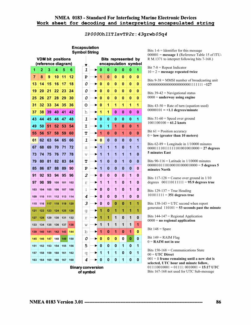
NMEA 0183 - Standard For Interfacing Marine Electronic Devices
NMEA 0183 Version 3.01 ------------------------------------------------------------------------ 86
NMEA 0183 - Standard For Interfacing Marine Electronic Devices
NMEA 0183 Version 3.01 ------------------------------------------------------------------------ 86
0 0 0 0 0 1
1 0 0 0 0 0
0 0 0 0 0 0
0 0 0 0 0 0
0 0 0 0 0 0
0 1 1 1 1 1
1 1 0 0 0 0
0 0 0 0 0 1
0 1 1 0 0 1
1 0 0 1 0 0
0 0 0 0 0 1
1 1 1 0 1 1
1 1 1 1 1 0
1 0 0 1 0 0
1 0 0 0 0 0
0 0 0 0 1 0
1 1 1 0 1 0
0 0 1 0 1 0
0 0 0 1 0 0
0 0 0 0 1 1
1 0 1 1 1 1
1 1 1 0 1 0
1 1 1 1 1 1
1 0 1 0 1 0
0 0 0 0 0 0
0 0 0 1 0 1
1 1 1 0 0 1
0 0 0 1 0 0
1
P
0
0
0
O
h
1
I
T
1
s
v
T
P
2
r
:
4
3
g
r
w
b
0
5
q
4
1 2 3 4 5 6
7 8 9 10 11 12
13 14 15 16 17 18
19 20 21 22 23 24
25 26 27 28 29 30
31 32 33 34 35 36
37 38 39 40 41 42
43 44 45 46 47 48
49 50 51 52 53 54
55 56 57 58 59 60
61 62 63 64 65 66
67 68 69 70 71 72
73 74 75 76 77 78
79 80 81 82 83 84
85 86 87 88 89 90
91 92 93 94 95 96
97 98 99 100 101 102
103 104 105 106 107 108
109 110 111 112 113 114
115 116 117 118 119 120
121 122 123 124 125 126
127 128 129 130 131 132
133 134 135 136 137 138
139 140 141 142 143 144
145 146 147 148 149 150
151 152 153 154 155 156
157 158 159 160 161 162
163 164 165 166 167 168
VDM bit positions(reference diagram)
Bits represented byencapsulation symbol
EncapsulationSymbol String
Binary conversionof symbol
Work sheet for decoding and interpreting encapsulated stringWork sheet for decoding and interpreting encapsulated string
0 0 0 0 0 1
1 0 0 0 0 0
0 0 0 0 0 0
0 0 0 0 0 0
0 0 0 0 0 0
0 1 1 1 1 1
1 1 0 0 0 0
0 0 0 0 0 1
0 1 1 0 0 1
1 0 0 1 0 0
0 0 0 0 0 1
1 1 1 0 1 1
1 1 1 1 1 0
1 0 0 1 0 0
1 0 0 0 0 0
0 0 0 0 1 0
1 1 1 0 1 0
0 0 1 0 1 0
0 0 0 1 0 0
0 0 0 0 1 1
1 0 1 1 1 1
1 1 1 0 1 0
1 1 1 1 1 1
1 0 1 0 1 0
0 0 0 0 0 0
0 0 0 1 0 1
1 1 1 0 0 1
0 0 0 1 0 0
1
P
0
0
0
O
h
1
I
T
1
s
v
T
P
2
r
:
4
3
g
r
w
b
0
5
q
4
1 2 3 4 5 6
7 8 9 10 11 12
13 14 15 16 17 18
19 20 21 22 23 24
25 26 27 28 29 30
31 32 33 34 35 36
37 38 39 40 41 42
43 44 45 46 47 48
49 50 51 52 53 54
55 56 57 58 59 60
61 62 63 64 65 66
67 68 69 70 71 72
73 74 75 76 77 78
79 80 81 82 83 84
85 86 87 88 89 90
91 92 93 94 95 96
97 98 99 100 101 102
103 104 105 106 107 108
109 110 111 112 113 114
115 116 117 118 119 120
121 122 123 124 125 126
127 128 129 130 131 132
133 134 135 136 137 138
139 140 141 142 143 144
145 146 147 148 149 150
151 152 153 154 155 156
157 158 159 160 161 162
163 164 165 166 167 168
VDM bit positions(reference diagram)
Bits represented byencapsulation symbol
EncapsulationSymbol String
Binary conversionof symbol
1P000Oh1IT1svTP2r:43grwb05q4
Bits 1-6 = Identifier for this message 000001 = message 1 (Reference Table 15 of ITU-R M.1371 to interpret following bits 7-168.) Bit 7-8 = Repeat Indicator 10 = 2 = message repeated twice Bits 9-38 = MMSI number of broadcasting unit 000000000000000000000001111111 =127 Bits 39-42 = Navigational status 0000 = underway using engine Bits 43-50 = Rate of turn (equation used) 00000101 = +1.1 degrees/minute Bits 51-60 = Speed over ground 1001100100 = 61.2 knots Bit 61 = Position accuracy 0 = low (greater than 10 meters) Bits 62-89 = Longitude in 1/10000 minutes 0000111101111111010010010000 = 27 degrees 5 minutes East Bits 90-116 = Latitude in 1/10000 minutes 000001011101000101000010000 = 5 degrees 5 minutes North Bits 117-128 = Course over ground in 1/10 degrees 001110111111 = 95.9 degrees true Bits 129-137 = True Heading 101011111 = 351 degrees true Bits 138-143 = UTC second when report generated 110101 = 53 seconds past the minute Bits 144-147 = Regional Application 0000 = no regional application
Bit 148 = Spare Bit 149 = RAIM Flag 0 = RAIM not in use Bits 150-168 = Communications State 00 = UTC Direct 001 = 1 frame remaining until a new slot is selected, UTC hour and minute follow, 011110010001 = 01111: 0010001 = 15:17 UTC Bits 167-168 not used for UTC Sub-message

NMEA 0183 - Standard For Interfacing Marine Electronic Devices
NMEA 0183 Version 3.01 ------------------------------------------------------------------------ 87
TABLE 8 - Copy of ITU-R M.1371 UAIS (TABLE 15)
Messages 1, 2, and 3: position reports
Parameter Number of bits
Description
Message ID 6 Identifier for this message 1, 2 or 3
Repeat Indicator
2 Used by the repeater to indicate how many times a message has been repeated. Refer to § 4.6.1; 0 - 3; default = 0; 3 = do not repeat any more.
User ID 30 MMSI number
Navigational status 4 0 = under way using engine, 1 = at anchor, 2 = not under command,3 = restricted manoeuvrability, 4 = Constrained by her draught; 5= Moored; 6 = Aground; 7 = Engaged in Fishing; 8 = Under way sailing; 9 = reserved for future amendment of Navigational Status for HSC; 10 = reserved for future amendment of Navigational Status for WIG; 11 - 14 = reserved for future use; 15 = not defined = default
Rate of turn ROT[AIS]
8 ± 127 (–128 (80 hex) indicates not available, which should be the default). Coded by ROT[AIS]=4.733 SQRT(ROT[IND]) degrees/min ROT[IND] is the Rate of Turn ( 720 degrees per minute), as indicated by an external sensor.+ 127 = turning right at 720 degrees per minute or higher; - 127 = turning left at 720 degrees per minute or higher
SOG 10 Speed over ground in 1/10 knot steps (0-102.2 knots) 1023 = not available, 1022 = 102.2 knots or higher
Position accuracy 1 1 = high (< 10 m; Differential Mode of e.g. DGNSS receiver) 0 = low (> 10 m; Autonomous Mode of e. g. GNSS receiver or of other Electronic Position Fixing Device) ; default = 0
Longitude 28 Longitude in 1/10 000 min (±180 degrees, East = positive, West = negative. 181 degrees (6791AC0 hex) = not available = default)
Latitude 27 Latitude in 1/10 000 min (±90 degrees, North = positive, South = negative, 91 degrees (3412140 hex) = not available = default)
COG 12 Course over ground in 1/10° (0-3599). 3600 (E10 hex)= not available = default; 3601 – 4095 should not be used
True Heading 9 Degrees (0-359) (511 indicates not available = default).
Time stamp 6 UTC second when the report was generated (0-59, or 60 if time stamp is not available, which should also be the default value, or 62 if Electronic Position Fixing System operates in estimated (dead reckoning) mode, or 61 if positioning system is in manual input mode or 63 if the positioning system is inoperative)
Reserved for regional applications
4 Reserved for definition by a competent regional authority. Should be set to zero, if not used for any regional application. Regional applications should not use zero.
Spare 1 Not used. Should be set to zero
RAIM-Flag 1 RAIM (Receiver Autonomous Integrity Monitoring) flag of Electronic Position Fixing Device; 0 = RAIM not in use = default; 1 = RAIM in use)
Communication State 19 See 3.3.7.2.2 and 3.3.7.3.2
Total number of bits 168

NMEA 0183 - Standard For Interfacing Marine Electronic Devices
NMEA 0183 Version 3.01 ------------------------------------------------------------------------ 88
7.3 Example Receiver Diagrams The illustrative diagrams in Figure 7 and Figure 8 show the example structure of two optoisolator based LISTENER circuits that offer overvoltage, reverse voltage and power dissipation protection for the optoisolator and serve to limit the current drawn from the line.
OPTO-ISOLATOR
A
B
Figure 8
OPTO-ISOLATORA
B
Figure 7
N-CHANNELFET
NPN
End of NMEA 0183 Version 3.01


![[XLS] National Bank.xls · Web viewRAJIV KUMAR 0183-2570024 bo4164@pnb.co.in HALL BAZAR, AMRITSAR J.P. SINGH 0183-5010652 0183-2543825 bo0018@pnb.co.in PUNJAB NATIONAL BANK HANSLI](https://img.dokumen.tips/doc/110x75/5aa125267f8b9a46238b5bc1/xls-national-bankxlsweb-viewrajiv-kumar-0183-2570024-bo4164pnbcoin-hall-bazar.jpg)