Embed Size (px)
Citation preview

SP a
Gra cl
NASA Conference Publication 2305
NASA CP i 2305 i 1 c.1
ceborne Gravity
iometers LOAN COPY: RETURN TO
AFWL TECHNICAL LISRARY KIRTLAND AFB, NM 87117
Proceedings of a workshop held at NASA Goddard Space Flight Center
Greenbelt, Maryland February 28-March 2, 1983
:
I I
https://ntrs.nasa.gov/search.jsp?R=19840010648 2018-09-08T13:09:28+00:00Z
TECH LIBRARY KAFB. NM
Illllllilllllll~MyIII#Il~IIIIIII 0097L94 NASA Conference Pubucaz;con muo
Spaceborne Gravity
Gradiometers
Edited by William C. Wells
Science Applications, Inc. McLean, Virginia
Proceedings of a workshop sponsored by the OSSA Geodynamics Branch and held at
NASA Goddard Space Flight Center Greenbelt, Maryland
February 28-March 2, 1983
National Aeronautics and Space Administration
Sdentific and Technical Information Branch
1984

_I. . . - - - ..___

FOREWORD
This volume contains the proceedings of the Spaceborne Gravity Gradiometer Workshop organized by the co-chairmen with the sponsorship of the NASA Office of Space Science and Applications. The Workshop was held at NASA Goddard Space Flight Center in Greenbelt, Maryland, February 28 through March 2, 1983. The invited principals included scientists and engineers specializing in geodynamics, gravity gradiometer instrument development and space mission planning.
The Workshop was relatively small and was conducted informally to encourage discussion of the issues. The presentations and discussions reviewed and assessed the current status of gravity gradiometers. The specific application being evaluated at the Workshop was a very sensitive instrument for Gravsat-B, a mission for the mid 1990's in a low altitude polar orbit.
Thanks are due to Mr. Werner Kahn of Goddard Space Flight Center, our host for the Workshop; Mr. Thomas Fischetti of NASA headquarters, our sponsor, and the staff of Science Applications, Inc., for their assistance with the organization of the Workshop and the preparation of his document.
Daniel B. DeBra William C. Wells
Co-Cha i rmen April 1983
WORKSHOP PARTICIPANTS
Dr. Georges Balmino CNESIGRGS Toulouse, France
Mr. Charles A. Bartholomew Naval Research Laboratory Washington, D. C.
Mr. Charles R. Baugher Marshall Space Flight Center Huntsville, Alabama
Dr. Peter L. Bender Joint Institute for Laboratory Astrophysics Boulder, Colorado
Mr. Alain M. Bernard ONERA Chatillion, France
Dr. Richard E. Brown Phoenix Corporation McLean, Virginia
Mr. James Buisson Naval Research Laboratory Washington, D. C.
Dr. Hinghung Chan University of Maryland College Park, Maryland
Mr. Allan B. Colquhoun University of Strathclyde Glasgow, Scotland
Prof. Daniel B. DeBra Stanford University Palo Alto, California
Prof. Marino Dobrowolny CNR Frascati, Italy
Mr. Thomas L. Fischetti NASA Headquarters Washington, D. C.
Dr. Walter Flury ESA/ESOC Darmstadt, West Germany
Dr. Robert L. Forward Hughes Research Laboratories Malibu, California
Prof. Franc0 Fuligni CNR Frascati, Italy
Dr. Mario D. Grossi Smithsonian Astrophysical Observatory Cambridge, Massachusetts
Dr. Roger Hastings Sperry Defense Systems St. Paul, Minnesota
Dr. Warren G. Heller The Analytic Sciences Corporation Reading, Massachusetts
Mr. Albert Jircitano Bell Aerospace/Textron Buffalo, New York
Dr. Stanley K. Jordan Geospace Systems Corporation Wellesley, Massachusetts
Mr. Werner D. Kahn NASA Goddard Space Flight Center Greenbelt, Maryland
Mr. Seymor Kant NASA Goddard Space Flight Center Greenbelt, Maryland
iv

WORKSHOP PARTICIPANTS (Continued)
Mr. George Knausenburger AFOSR Washington, D. C.
Dr. Nicholas A. Lockerbie University of Strathclyde Glasgow, Scotland
Dr. Evan Mapoles Stanford University Palo Alto, California
Mr. Ernie H. Metzger Bell Aerospace/Textron Buffalo, New York
Mr. Marvin J. Molny Sperry Systems Management Great Neck, New York
Dr. M. Vol Moody University of Maryland College Park, Maryland
Mr. James P. Murphy NASA Headquarters Washington, D. C.
Dr. Ho Jung Paik University of Maryland College Park, Maryland .
Dr. William L. Piotrowski NASA Headquarters Washington, D. C.
Dr. Vincent Piscane Applied Physics Laboratory Laurel, Maryland
Dr. Victor S. Reinhardt Bendix Field Engineering Columbia, Maryland
Dr. Walter J. Senus Defense Mapping Agency Washington, D. C.
Dr. David E. Smith NASA Goddard Space Flight Center Greenbelt, Maryland
Dr. Martin M. Sokoloski NASA Headquarters Washington, D. C.
Dr. David Sonnabend Jet Propulsion Laboratory Pasadena, California
Mr. Milton B. Trageser C.S. Draper Laboratory Cambridge, Massachusetts
Dr. John Turneaure Stanford University Palo Alto, California
Dr. Emanual Tward Jet Propulsion Laboratory Pasadena, California
Dr. Friedrich 0. von Bun NASA Goddard Space Flight Center Greenbelt, Maryland
Dr. William C. Wells Science Applications, Inc. McLean, Virginia
Dr. Richard Pomphrey NASA Headquarters Washington, D. C.
V


TABLE OF CONTENTS Page
FOREWORD......................... iii
WORKSHOP PARTICIPANTS . . . . . . . . . . . . . . . . . . iv
ACRONYMNS . . . . . . . . . . . . . . . . . . . . . . . . viii
I. SUMMARY AND RECOMMENDATIONS . . . . . . . . . . . . . . . 1
A. Purpose and Objectives ............... 1 B. Organization of the'workshop and Report . : .... C. Sumnary of Proceedings ............... : D. Recommendations .................. 10
II. ROLE OF GRAVITY GRADIOMETERS IN NASA'S PROGRAMS . . . . . 13
A. Geopotential Research Program ........... 13 B. Solar System Exploration Program .......... 19
III. INSTRUMENT STATUS AND PROSPECTS . . . . . . . . . . . . . 23
A. B. C. D.
E.
F. G.
H.
I.
J.
Rotating Gravity Gradiometer (Hughes) . . . . . . . 23 Spherical Gravity Gradiometer (Draper) . . . . . . . 28 Rotating Accelerometer Gravity Gradiometer (Bell) . 30 Gradio - Orbital Gravity Gradiometry through Differential Microaccelerometry (CNES/ONERA) . . . . 30 Superconducting Gravity Gradiometer with SQUID Readout (Maryland) . . . . . . . . . . . . . . . . . 34 SAO/PSN Instruments A Superconducting Gra;ity'G;adiomet&-'to Aid ' ' . '
37
Intertial Navigation Systems (Strathclyde) . . . . . 41 A Supersensitive Accelerometer for Spacecraft Gradiometry (Bendix) . . . . . . . . . . . . . . . . 42 Application of Superconducting Cavity Oscillators to Mass-Spring Gradiometers (Stanford) . . . . . . . 45 Design Considerations for a Cryogenic Gravity Gradiometer (Sperry) . . . . . . . . . . . . . . . . 47
IV. COMMON PROBLEMS . . . . . . . . . . . . . . . . . . . . . 51
A. Sensors ...................... 51 B. Testing ...................... C. Spacecraft ..................... :: D. Data Processing .................. 62
V. DEVELOPMENT PLAN . . . . . . . . . . . . . . . . . . . . 67
A. Critical Steps ................. ; . 67 B. Development Schedule ................ 70 C. Cost Considerations ................ 72
REFERENCES . . . . . . . . . . . . . . . . . . . . . . . 75
vii

ACRONYMS
AFOSR A0 CNES CNR DISCOS ESA ESOC FET GEM GEOS GGM GRGS GRM IFS1 IRAS NRC ONERA POLO PSN SAO SC0 SQUID SSEC TSS
Air Force Office of Scientific Research Announcement of Opportunity Centre Nationale d'Etudes Spatiales (France) Consiglio Nazionale delle Ricerche (Italy) Disturbance Compensation System European Space Agency European Space Operations Center Field Effect Transistor Goddard Earth Model Geodynamic Experimental Ocean Satellite Gravity Gradiometer Mission Groupe de Recherches de Geodesie Spatiale (France) Geopotential Research Mission Instituto di Fisica dello Spazio Interplanetario (Italy) Infrared Astronomical Satellite National Research Council Office National d'Etudes et de Recherches Aerospatiales (France) Polar Orbiting Lunar Observatory Piana Spaziale Nazionale (Italy) Smithsonian Astrophysical Laboratory Superconducting Cavity Oscillator Superconducting Quantum Interference Device Solar System Exploration Committee Tethered Satellite System
viii
A. Purpose and Objectives
The& purpose of the Spaceborne Gravity Gradiometer Workshop was to consider a program leading to the development in the 1990's of an instrument for global mapping of the gravity fields of the Earth and eventually the planets. The instrument objective was to obtain significantly better measurement accuracy and spatial resolution than would be possible by 1990 using spacecraft tracking techniques. The specific tasks for the Workshop were to identify technical problems, and to recommend or identify solutions. The results of the Workshop became the basis of a long-term plan for instrument development.
This workshop represents NASA's first comprehensive assessment of gravity gradiometer technology that could be available in the 1990's. Earlier NASA study contracts considered Earth-orbiting instruments with much less sensitivity (Forward, et al, 1973, and Metzger, et al, 1976)than the more recent efforts (Paik, 1981 a, b; Grossi, 1981; Reinhardt, et al, 1982). In 1981, a NASA workshop considered the application of gravity gradiometry to the mapping of the global lunar gravitational field as a NASA contribution to the European Space Agency's Polar Orbiting Lunar Observatory (POLO) mission (Wells, ed., 1981). Subsequent study indicated that the available instrument concepts were adequate for immediate applications to lunar and planetary missions (Wells, 1981).
B. Organization of the Workshop and Report
The two-and-one-half-day workshop was held Monday through Wednesday, February 28 to March 2, 1983, at the NASA Goddard Space Flight Center in Greenbelt, Maryland. The logistical arrangements were coordinated by Dr. William C. Wells, of SAI. The topics and speakers for the workshop were selected by Thomas L. Fischettiof NASA Headquarters and Werner D. Kahn of Goddard Space Flight Center, and arranged into the agenda given in Table l-l. The first morning was devoted to presentations on NASA's Geodynamics Program, and on the status and prospects for seven different gravity gradiometer concepts. The afternoon was occupied by a discussion of
1
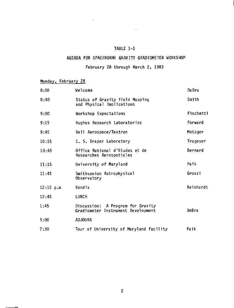
TABLE l-l
AGENDA FOR SPACEBORNE GRAVITY GRADIOMETER WORKSHOP
February 28 through March 2, 1983
Monday, February 28
8:30
8:40
9:oo
9:15
9:45
10:15
10:45
11:15
11:45
12:15 p.m
12 :45
1:45
5:oo
7:30
Welcome
Status of Gravity Field Mapping and Physical Imp1 ications
Workshop Expectations
Hughes Research Laboratories
Bell Aerospace/Textron
C. S. Draper Laboratory
Office National d'Etudes et de Researches Aerospatiales
University of Maryland
Smithsonian Astrophysical Observatory
Bendix
LUNCH
Discussion: A Program for Gravity Gradiometer Instrument Development
ADJOURN
Tour of University of Maryland Facility
DeBra
Smith
Fischetti
Forward
Metzger
Trageser
Bernard
Paik
Grossi
Reinhardt
DeBra
Paik
TABLE l-l (continued)
AGENDA FOR SPACEBORNE GRAVITY GRADIOMETER WORKSHOP
February 28 through March 3, 1983
Tuesday, March 1
8:30 a.m. Orbital Flight Opportunities
8:45 Discussion: Laboratory and Orbital Test Requirements
lo:oo Discussion: Spacecraft Requirements
11:15 Discussion: Data Processing
12:30 LUNCH
1:30 Discussion: Gradiometer Instrument Development Plans
3:oo
4:15
Discussion: Workshop Recommendations
ADJOURN
Piotrowski
Forward
Kant
Heller
DeBra
DeBra
Wednesday, March 2
8:30 a.m. Preparation of Report Contributions
12:30 a.m. ADJOURN
3

measurement objectives and an identification of basic instrument development problems. In the evening, the workshop participants were invited to tour Dr. Paik's laboratory at the University of Maryland and see his gravity gradiometer sensor and test facility. The Tuesday morning discussions
focused on three problems common to all instruments: ground and flight testing, spacecraft requirements, and data processing. The afternoon
session completed consideration of sensor development problems and developed conclusions and recommendations. The final morning was used for writing contributions to this report.
Over forty scientists and engineers were invited to attend the workshop on the basis of their experience in geopotential research, space mission planning, or gravity gradiometer instrument development. The participants came from NASA Headquarters, NASA Centers, universities, and industry, and included several foreign representatives. (The list of participants is on
pages iv and v.)
This report captures the presentations, discussions, and progress made
at the workshop. The first section covers the goals, objectives, and
organization of the workshop. It ends with a summary of the proceedings and the recommendations of the w.orkshop. The role of gravity gradiometers in NASA's future programs is the subject of the second section. Brief summaries of each instrument concept, including its status and prospects, are found in the third section. The discussions of sensor, testing, spacecraft, and data processing problems are reported in the fourth section. The final section contains NASA's proposed plan for the development of
gravity gradiometry as a measurement technique.
.
C. Summary of Proceedinqs
Opening remarks by Dan DeBra, the co-chairman for the Workshop, from
Stanford University and by Tom Fischetti of NASA Headquarters provided the background and objectives for the Workshop. NASA is currently seeking approval to begin the Geopotential Research Mission (GRM) and is interested in gravity gradiometers as a follow-on to GRM. NASA needs recommendations
for an advanced development effort which would bring understanding of gravity gradiometers to the mission readiness level at about the time that
GRM is launched.

Present knowledge of the Earth's gravity field and immediate prospects for improvements through better use of existing data were described by Dave Smith of Goddard Space Flight Center. He predicted that gravity anomalies with 100 km dimensions will be determined to 2 mgal in the final GRM data.
Greatly improved geophysical' interpretations are expected. A ration-
ale for further increases in sensitivity and spatial resolution was offered based on geological processes that have surface dimensions comparable to the thickness of the Earth's crust, typically 30 to 50 km for continents.
The first three presentations on instrument status and prospects were on orbital application of conventional (i.e., room temperature) techniques
developed for use on moving vehicles (airplanes, ships, etc.). Bob Forward of Hughes Research Laboratories described two Rotating Gravity Gradiometers; one exists as a laboratory prototype and has been proposed for lunar orbital missions while the other was a concept for a larger, more sensitive Earth orbital instrument. A Rotating Accelerometer gravity gradiometer developed by Ernie Metzger at Bell Aerospace/Textron is currently being tested on board the USS Vangard, a Navy ship. For space applications, space-qualified miniature electrostatic accelerometers would be used rather than the pendu- lous accelerometers employed in the current design. The Spherical Gravity Gradiometer that exists as a laboratory prototype was the subject of a presentation by Milt Trageser of the Charles Stark Draper Laboratories.
Orbital gravity gradiometry through differential microaccelerometry is the basis for a French mission concept known as Gradio. Alian Bernard of the Office National d'Etudes et de Recherches Aerospatiales (ONERA) explained how this concept takes advantage of the microgravity space environment to achieve about 10-2 E sensitivity for a modest size, room temperature instrument.
The remaining three presentations concerned the status and prospects for superconducting gravity gradiometers operating at cryogenic temperatures. Ho Jung Paik of the University of Maryland described gravity gradient sensors in which a superconducting quantum interference device (SQUID) is the key element to a basic and very sensitive accelerometer. A
5
reduced scale prototype sensor has been built and tested to the limits permitted in the laboratory.
International collaborations between the U.S. and Italy are supporting
the development of the Tethered Satellite System and technology for gravity gradiometers. As outlined by Mario Grossi of the Smithsonian Astrophysical Observatory in the TSS program, the tether and the systems for its
deployment, control and retrieval are the responsibility of the U.S. while the subsatellite and some of the scientific instrumentation will be provided
by Italy. Gravity gradiometer concepts are being studied that use both SAO's superconducting cavity oscillators and Italian capacitive probes as displacement transducers.
Victor Reinhardt of Bendix Field Engineering described a concept developed in a joint effort with Stanford University and Goddard Space Flight Center which employs a superconducting cavity oscillator to convert the displacement of the proof mass to an easily measured frequency shift. A development program starting with a room temperature test model followed by a cryogenic superconducting version is planned.
After a break for lunch, Dan DeBra lead the wide-ranging afternoon discussion concerning the definition of an instrument development program for gravity gradiometers. An appropriate measurement objective was the first topic discussed. It was agreed that a factor of ten improvement over GRM for gravity anomalies in the 100 to 400 km size range should be
attempted. A gravity gradiometer noise level of 3x10⁻⁴ E Hz-112 was selected as being consistent with this objective. Assuming that the gravity gradiometer could be operated at about the same altitude as GRM, then with increased sensitivity the spatial resolution would be better. However, no spatial resolution goal was set, primarily because the requirement for instrument noise is very sensitive to the desired spatial resolution and is
also difficult to calculate.
Key sensor design options were identified, namely single-axis vs. full
tensor measurements, spinning vs. inertial orientations, and room.vs. cryogenic temperatures. In general, the second option is more difficult to incorporate into the mission, but is expected to be the more attractive
6

option from an instrument performance standpoint. Low temperature
technology is especially advantageous in that it offers:
lower thermal noise better mechanical stability superconductivity (no electrical losses and excellent magnetic
shielding) superfluidity (very high thermal conductivity) quantum stability
These properties are responsible for the high sensitivities predicted in Table l-2 for spaceborne superconducting gravity gradiometers. The disadvantages are the added system for maintaining the cryogenic temperature and the extra isolation of the sensor from the external systems so that transfer of power, signals and orientation is more difficult.
On Monday evening, the participants visited the University of Maryland to see what is being done there to develop cryogenic gravity gradiometers. The group toured the shops and laboratories where test equipment, develop- ment hardware and some test results were on display, The informal tour stimulated many discussions. The steady progress in the development program at Maryland was very evident.
Overall NASA plans for future Earth and planetary missions was the subject of the opening presentation on Tuesday morning. Bill Piotrowski, NASA Headquarters, described Spacelab missions using radar and optical sensors to study Earth resources, other STS opportunities using available space in the middeck or cargo bay areas, or the Tethered Satellite System, and free-flying spacecraft (including GRM). Also discussed was the core program of planetary missions recently recommended by the Solar System Exploration Committee (SSEC), specifically a Venus Radar Mapper, a Mars Geoscience/Climatology Orbiter, a Comet Rendezvous/Asteriod Flyby, and a Titan Probe/Radar Mapper. Ten additional candidate missions were identified by SSEC.
Bob Forward lead a discussion on instrument testing. The first of three topics concerned with development problems common to all sensors. A
7

TABLE 1-2
A SUMMARY 0.F SENSITIVITIES FOR EXISTING AND PROPOSED GRAVITY GRADIOMETERS
Instrument Type Developers
Conventional (room Bell Aerospace temperature), measured C.S. Draper Lab. in laboratory Hughes
Sensitivity, E Hz-112
1 to 5
Conventional, proposed for space
Above plus CNES/ONERA SAO/PSN
Cryogenic, measured in laboratory
Cryogenic, proposed for space
n
Maryland
Maryland Bendix/Stanford SAO/PSN Sperry Strathclyde
0.03 to 1.0
0.7
10-4 to 10-3
8

complete sensor error model was advocated as a means of understanding the methods by which noise is coupled into the sensor during experimental tests and normal operation. Laboratory tests were supported as being useful for verifying the error model. The Earth's gravity and other environmental noise in the laboratory were perceived as precluding a demonstration of sensor noise at the level desired in orbit. Thus, construction of an orbital test facility was suggested. The available information on spacecraft environments was perceived as being inadequate and, therefore, required immediate analytical estimates followed by orbital measurements.
Consideration of the second discussion topic, spacecraft design issues raised by gravity gradiometer support requirements, was guided by Seymor Kant, Goddard Space Flight Center. Among the issues covered were attitude control, orbit inclination, low altitude operation using a tether or propulsion system, vibration, and temperature control. Options and potential solutions were identified for all issues based on experience with such missions as the Geopotential Research Mission, Infrared Astronomical Satellite and Gravity Probe-B.
The discussion of data processing, the last common problem topic, was directed by Warren Heller, The Analytic Sciences Corporation. Requirements for three types of auxiliary data were identified, namely ephemeris, near field mass distribution and engineering data. This information is used to correct and calibrate the instrument data. The key computational problem is the recovery of useful geodetic quantities such as gravity anomalies or mass distributions from the gravity gradient measurements at satellite altitude. Several local and global solution techniques were proposed. Immediate development efforts were advocated for both approaches in order to improve computational procedures and check on one another.
There was also a discussion of sensor development under the leadership of Dan DeBra. Several general ideas were presented at this time. Allan Colquhoun from the University of Strathclyde talked about the use of thin films for the coils and SQUIDS in superconducting sensors. Future improve- ments to his technique include fabrication of a crystaline proof mass and integration with sensor and electronic circuits operating at cryogenic temperatures. A superconducting instrument concept incorporating some novel design techniques taken from conventional system designs was described by
9

Roger Hastings of Sperry Defense Systems. More ideas for improving the performance of superconducting sensors were offered by Evan Mapoles from Stanford University.
A consensus on the Workshop's recommendations was achieved in a discussion session on Tuesday afternoon (see below). Preliminary written material was prepared the following morning.
D. Recommendations
The Workshop made an overall recommendation for NASAto undertake a program to "develop a flight qualified gravity gradiometer for use in the 1990s on Earth orbit and planetary missions." Seven recommendations were formulated to identify specific problems in the areas of sensors, testing, spacecraft design and data processing that should be incorporated in the
development effort. They are:
1. Conduct analyses of instrument configurations and mechanizations for optimum performance. These analyses should focus on the following topics:
a. Dynamic range requirements for spinning and inertial sensors in various orientations, especially those that reduce the large constant gravity gradient of about 3000 E.
b. The relative merits of full tensor measurements and redundant measurements of specific tensor components.
C. Instruments with an internal inertial navigation capability or a reduced sensitivity to orientation errors.
d. Incorporation of conventional system techniques for noise
reduction (e.g., synchronous detection, force feedback, and floated suspensions) into instruments with cryogenic detectors.
e. Adaptation of the sensor to planetary missions.
2. Implement the development of sensor technologies that contribute to the desired capability. Specific examples are Superconducting Quantum Interference Devices, Superconducting Cavity Oscillators, low temperature preamplifiers , and suspensions for proof masses.
10
3. Estimate and eventually obtain actual measurements of important spacecraft environmental parameters, in particular vibration, atti- tude rates, and temperature stability.
4. Develop an orbital test program that will allow instruments to be tested and calibrated in the actual spacecraft environme.nt.
5. Analyze problems in the design of the spacecraft systems that are due to requirements for:
a. achieving quiet vibration and attitude rate'environments. b. keeping the sensor at a low altitude using either a propulsion
system or a tether. C. maintaining cryogenic temperatures with dewars or non-
mechanical refrigerators. (The latter is essential for planetary missions.)
6. Compute the performance of a gravity gradiometer in low Earth orbit with a system noise level of about 3x10⁻⁴ E in a l-second integration period.
7. Simulate the analysis of gravity gradiometer data to validate processing strategies and to anticipate computational problems involved in the downward continuation to meaningful geophysical quantities.
11


I
II. ROLE OF GRAVITY GRADIWETERS IN NASA’S PROGRAMS
Within the Office of Space Science and Applications, both the Geopoten- tial Research Program and the Solar System Exploration Program have an interest in gravity field measurements and, consequently, in the use of
gravity gradiometers for the acquisition of such data. The projected role of gravity gradiometers in both programs is described in this section.
A. Geopotential Research Proqram
The Geopotential Research Program is concerned with the Earth's gravity and magnetic fields. The scope of the program includes analysis of existing data to produce models of the fields, scientific interpretations of the models and the development of instruments and missions that can collect better data and produce improved models and interpretations.
1. Present Knowledge
Our present knowledge of the Earth's gravitational field is based on
information from many sources. Ground based measurements of gravity and deflections of the vertical can be combined with leveling data to give information on both the topography and the undulations of the geoid. A large amount of data is available in North America and Europe, but measure- ments are scarce in most parts of the other continents. Ship-board gravity measurements provide a valuable extension of the data base in areas where considerable numbers of ship tracks are available. However, the most accurate worldwide information on the geoid at present comes from altimeter data for oceanic areas and from the tracking of a number of satellites for continental areas.
Over the last decade, NASA has been providing increasingly more com- plete state-of-the-art gravity models to the science and applications com- munities. These models, called Goddard Earth Models (GEM), are the best available and are used worldwide. The GEM-9 gravity field model (Lerch et al., 1977, 1979) was determined from tracking data on 30 satellites with a wide range of inclinations, eccentricities, and altitudes. It is complete to degree 22, and includes some additional selected terms. The same satellite data plus surface gravity data are the basis of the GEM-10 model.
13

Additional gravity field models GEM-1OB and GEM-1OC (Lerch et al., 1981) have been derived by combining GEOS 3 altimeter data with the data used to derive GEM-lo. They are complete and have the same coefficients through degree 36; GEM-1OC has selected terms through degree 180. The present
accuracy of the best gravity field model, GEM lOC, is approximately 20 mgal for lo x lo squares in continental and ice covered regions. Over the oceans i" x lo squares are known typically to about8 mgals. Another satellite- only field, GEM-L2, has been derived by combining GEM-9 with Lageos tracking data during the period 1979-1981. It has a long wavelength geoid (to degree and order 4) assessed to be accurate to +8 cm.
Some improvements in the present gravity field models could be made by using additional data and reprocessing some of the earlier data, as recom- mended by the NASA Gravity Field Workshop (1982). Accurate laser range data for Lageos and Starlette, which have very stable orbits, have not been included in the models discussed above. The use of additional tracking data for geosynchronous satellites and for some of the Transit Navy Navigation Satellites if it can be obtained would further improve the results. How- ever, available data cannot provide appreciable improvement in our knowledge of the shorter wavelength gravity field variations over most of the conti-
nents, which is needed for understanding tectonic processes and evolution of the lithosphere. New gravity field mapping information also is necessary over the oceans, since oceanographers must have an independently determined geoid in order to derive the ocean currents from the new altimeter data
expected from the Topex mission.
2. Geopotential Research Mission (GRM)
It has been clear for some time that very much improved knowledge of the Earth's gravity field could be obtained from both satellite-to-satellite tracking (SST) and gravity gradiometry. Some SST experience was gained by using the ATS-6 satellite in geosynchronous orbit to track satellites in low orbits, namely, the Nimbus-6, Geodynamics Experimental Ocean Satellite (GEOS-3) and the command module for the Apollo-Soyuz Test Project (von Bun, et. al., 1980). Extensive SST studies have been done for the Geopotential
Research Mission, which is expected to fly in 1992. The mission concept is to make SST measurements between two spacecraft in the same nearly circular
polar orbit at a low enough altitude to obtain gravity data with an accuracy
14

I -
10
8
6
4
2
0 I I I I 500 1000 1500
SPATIAL RESOLUTION (KM)
2000 2500
Figure 2-l. EXPECTED ACCURACY BEFORE AND AFTER THE GEOPOTENTIAL RESEARCH MISSION
15
of about 2 mgal at a resolution (half-wavelength) of 100 km. Global magne- tic field measurements would be made by one of the satellites throughout the
mission. A Disturbance Compensation System (DISCOS) will be included on each spacecraft to eliminate the effects of atmospheric drag and other non-
gravitational forces to below lo-10 g.
The accuracy expected for measuring the relative velocity of the two spacecraft is one micron/set (10-6 m/s) or better with a time resolution of 4 sec. The resulting improvement in knowledge of the Earth's gravity field, compared to GEM-1OB is shown in Figure 2-l. The new gravity data are very significant because many important geologic structures and ocean phenomena
have gravity signatures that will be seen by GRM. Some geologic examples, in order of decreasing gravity signature , are subduction zones, mountain
ranges, mantle convection, ocean rise volcanism and sedimentary basins. The interesting ocean currents are the circumpolar , western boundary, equatorial and eastern boundary currents. Time-dependent eddies and seasonal varia-
tions can also be detected. More accurate altimetry data are required for
interpretation of the ocean gravity data.
Laboratory.tests with a 91 GHz measurement system indicated that random noise in measuring changes in the spacecraft separation would be roughly 0.1 micron for the same time resolution. Ray et al., (1982) give an allowable
proof mass disturbance spectrum which would produce the same geoid error as white noise velocity errors of 10-T m/s r.m.s., and the lowest level is 4x10⁻¹⁰ g/(rad/sec)l/2. The integrated allowable spurious acceleration over the range 0.001 to 0.5 rad/sec is 3.5x10⁻⁹ g. Thermal and other distortions
within the measurement system, deviations from roundness of the proof mass
in the DISCOS, and errors in measuring the proof mass position with respect to the cavity all have been considered, and are consistent with the stated overall measurement accuracy goal of one micron/set or better. However, a
sophisticated post-flight analysis of the proof mass position data will be needed (Ray et al., 1982). The use of a second measurement frequency of
42 GHz to permit the removal of systematic errors due to the ionosphere is planned.
Nearly all error analyses for GRM so far have been based on the assump- tion of random uncorrelated errors in the relative spacecraft velocity. For
a 6 months duration miss ltitude, 3 degree spacecraft sepa- #ion with 160 km a
16

I --
ration, and 1 micron/set measurement accuracy, the resulting geoid undula- tion uncertainty for all degrees from 2 through 180 would be about 1 cm (Colombo, 1981a; Breakwell, 1980). This compares with a present uncertainty of about 70 cm for short wavelengths and 8 cm for long wavelengths (Gravity Field Workshop, 1982).
3. Gravity Gradiometers
The Geopotential Research Program supports the development of cryogenic gravity gradiometers as a means to improved measurement capabilities in the 1990s. The long-term objective (beyond GRM) is an accuracy of 0.5 to 1.0
mgal at a spatial resolution (half wavelength) of 50 km. Furthermore, there is interest in being able to study features whose size is comparable to the thickness of the lithospheric crust, or 25 km.
As discussed elsewhere in this report, gravity gradiometers with accuracies of 10 -2 to 10-4 E (1 Eotvos is 10-9 (cm/sec2)cm) could be developed. The early planning for the GRM considered gravity gradiometers and satellite-to-satellite tracking as candidate measurement techniques. The GRM evaluation demonstrated that a gravity gradiometer with an accuracy of about 10-2 E and SST with lo- 6 m/set accuracy were approximately equiva- lent in their ability to measure gravity anomalies (see Figure 2-2). A more sensitive gradiometer can detect gravity anomalies associated with smaller geologic structures, as well as providing more detailed data on features that will be detected by GRM.
Figure 2-2 is based on an error analysis (Kahn, private communication) performed to assess the accuracy of gravity anomaly recovery for gradiometer systems having different levels of precision. Three block sizes, or levels of spatial resolution, were considered, namely: OO.25 (28 km), OO.5 (55 km), and lo.0 (110 km). For this study, the a priori uncertainties in the normalized spherical harmonic coefficients of the truncated series expansion of the earth's gravity field were represented by a covariance function based on Kaula's rule, namely:
R
(2a + 1) (lo-5/c2)2
17

8-
6-
4-
2-
1 .O Um/sec (EXPECTED GRM PERFORMANCE)
6 MONTH MISSION AT 160 KM ALTITUDE
I I I I 0
I 25 50 75 100 1;
SPATIAL RESOLUTION (KM)
i
Figure 2-2. EXPECTED GRAVITY GRADIOMETER ACCURACY
18
A priori knowledge of the gravity field limits the accuracy of the gravity anomalies measured by both GRM and gradiometers. This accounts for the relatively modest improvement in gravity anomaly accuracy, shown in Figure 2-2 as the instrument precision is increased from 10-2 to 10-d E.
To allow an unbiased comparison between gravity gradiometry and satellite-to-satellite tracking, and to take advantage of the lowest orbit ever planned for a long-lifetime (at least 6 months) satellite, the error analysis assumed the same 160 km operational orbit for the gradiometer as is planned for GRM. This is important because the accuracy of gravity measure- ments is greater at altitudes below 160 km and less above 160 km. However,
over a reasonable range of altitudes around 160 km, including altitudes that could be reached by a 100 km tether operated below the shuttle orbiting at about 225 km, gradiometer data are superior to that anticipated from GRM.
B. Solar System Exploration Program
The identified goals for solar system exploration are so broad, e.g., determination of the origin, evolution, and present state of the solar system, that the gravity field and many other observations are logically included within the scope of the program. The strategy for studying a solar system body follows a logical sequence of steps. The first step, reconnaissance, is usually accomplished by a flyby spacecraft. The program
places a high priority on completing the reconnaissance missions to yet unvisited bodies, particularly asteroids and comets. Orbiters, atmospheric probes and surface landers are employed during the exploration phase. Where there is special interest, exploratory missions are being planned to bodies that have already been visited. This discussion concentrates on the exploratory orbiter missions, because global gravity mapping is a natural objective of these missions, and because gradiometers are candidate orbiter instruments. Eventually, there may also be an opportunity to use a gravity gradiometer as part of an intensive study mission, e.g., sample return.
1. Present Knowledge
A reconnaissance mission typically provides a great improvement in our knowledge of a body's mass, and the low degree zonal harmonics of its
19
gravity field (i.e., J2 and J4). For the moon, Mars, and Venus, the following orbital missions have provided an initial gravity map:
moon Lunar Orbiter, Apollo command modules, Apollo subsatellites
Mars Mariner 9, Viking Venus Pioneer Venus
These maps have been made by analysis of navigation data, specifically, the Doppler shift in the frequency of the radio tracking signal due to a change in the radial velocity of the spacecraft relative to the receiving station. The analysis of the tracking data yields the line-of-sight acceleration at the orbital altitude caused by gravity anomalies after all other known effects have been accounted for.
The accuracy, resolution, and coverage of these maps is determined by tracking system performance and the orbit parameters. For planetary missions, the radial velocity can be measured with an accuracy of about 1 mm/set. For Mars and Venus, the orbits have been elliptical so that alti- tudes up to 2000 km have been needed to get good coverage. This places spatial resolution at the 1000 km level, and anomaly accuracy at about 50 mgal. For the moon, no data are available for the far side; however, good data (20 km resolution and 5 mgal accuracy) were obtained by the Apollo subsatellites for the nearside equatorial region.
Significant gravity anomalies are present. The moon has "mascons" that are associated with the circular mare; Mars has gravity anomalies over its
large volcanoes , and Venus has a few mountains and plains that rise well above an otherwise flat surface. The existing data has been used to estimate the thickness of the mare basalts, and the stresses and thickness of the crusts that support anomalous features.
2. Core Program
The Solar System Exploration Committee has defined a core program for
planetary exploration through the year 2000. The initial core missions are:
20

Venus Radar Mapper Mars Geoscience/Climatology Orbiter Comet Rendezvous/Asteroid Flyby Titan Probe/Radar Mapper
The first two missions , which are planned to be launched in 1988 and 1990, will orbit bodies for which gravity data are available. More tracking data will be obtained; however, a significant improvement in knowledge of the gravity field is not expected. They may, however, aid interpretation by providing a good topographic map of Venus (1 km surface resolution) and a determination of the global surface composition of Mars. The low-cost philosophy being applied to these missions, as well as the elliptical orbits planned, appears to preclude the use of gravity gradiometers on these missions in an attempt to obtain more meaningful data. The comet rendezvous and Titan probe missions in the core program do not even plan to orbit these very interesting bodies.
Ten candidate subsequent missions have been identified for continued studies of the inner planets, outer planets, and small bodies; they are:
Inner Planets Mars Aeronomy Orbiter Venus Atmospheric Probe Mars Surface Probe Lunar Geoscience Orbiter
Outer Planets Saturn Orbiter Saturn Flyby/Probe Uranus Flyby/Probe
Small Bodies ,Comet Atomized Sample Return Multiple Mainbelt Asteroid Orbiter/Flyby Earth Approaching Asteroid Rendezvous
Of these missions, the Lunar Geoscience Orbiter has the best justifica- tion for a gravity gradiometer, namely the acquisition of far side gravity data without a requirement for a separate communications relay satellite. A gradiometer with 1 E accuracy can meet the stated objective of measuring anomalies with 5 mgal precision along 1000 km paths; it may be able to
21

. _... -_ .--
provide 1 mgal resolution over smooth areas, and extend the 5 mgal accuracy to global coverage.
All orbiter (or rendezvous) missions could benefit from use of gradio- metry. Complete coverage can be obtained more quickly because gradiometers are not affected by the occultation and ground station scheduling problems that are encountered with radio tracking. Missions producing smaller amounts of data could reduce communications time significantly. In addi- tion, a gradiometer would permit on-board automation of orbit computation
and control; this would be helpful for outer planet orbiters where round trip communication times are long, and for reducing time devoted to communi-
cations with any orbiter. The benefits apply to more ambitous missions such as sample returns that are beyond the resources envisioned for the core program.
In conclusion, gradiometry could provide more accurate gravity data for many planetary missions than current tracking methods permit. If the tech- nique is developed for use in Earth or lunar orbit, then the instrument is more likely to be considered seriously when science payloads are selected. It is especially important that the potential performance (lo-2 to 10-d E) be known when the science objectives are formulated, because then an objective might be adopted that is beyond the capability of the existing
radio tracking systems.
22
III. INSTRUMENT STATUS AND PROSPECTS
Brief descriptions of gravity gradiometer instruments are included here to indicate the status and prospects of each concept.
A. Rotating Gravity Gradiometer (Hughes Research Laboratories)
The rotating gravity gradiometer is a resonant cruciform mass-spring system with a torsional vibration. In operation, the sensor is rotated about its torsionally resonant axis at an angular rate which is exactly one half the torsional resonant frequency. When a gravitational field is present, the, differential forces on the sensor resulting from the gradients of the gravitational field excite the sensor structure at twice the rotation frequency. The differential torque, T, between the sensor arms at the doubled frequency, is coupled into the central torsional flexure. The strains in this flexure are sensed with piezoelectric strain transducers which provide an electrical output.
Since the rotating gravity gradiometer moves through the gravity gradient field and obtains a' continuous sample of the field components in its plane of rotation, the output of the gradiometer contains two independent measurements of certain components of the gravity gradient field tensor. The two measurements appear as two sinusoidal signals in quadrature
AT = $ [(Txx - ry,) cos 2wt + 2r sin 2wt . xy 1
One output is a measurement of the difference between two of the diagonal components and the other measures the cross product component of the gravity gradient tensor in the coordinate frame of the sensor.
1. Earth-like Planetary Bodies
The sensor developed for the earth orbital application can also be used to obtain gravity gradient maps of Venus, Mars, Titan, and Triton. The desirability of obtaining 0.01 E sensitivity dictated the requirement for a sensor arm length as long as possible. A sensor arm length of 76 cm from center to center of the end masses (86 cm overall) was selected as the
23

largest arm diameter possible for the 96 cm spacecraft diameter, which, in turn, was dictated by the Scout payload envelope of 106.5 cm diameter. The chosen arm end masses were 2 kg each; this weight was considered reasonable for the size of the sensor.
A 35 set sensor time constant was chosen for the sensor by using
the time required for the spacecraft to pass through one resolution element at the nominal altitude of 270 km at the orbital velocity of 7.75 km/set.
With this size, weight, and time constant for the sensor, the thermal noise
caused by the Brownian motion of the sensor structure had an equivalent noise level of 0.007 E. This sensor system time constant is the smoothing time to be used in the sensor data preprocessing. The smoothed sensor output would be sampled approximately once every 5 set to overcome digitali- zation noise, prevent aliasing, and pick up strong, short period signals resulting from dense localized anomalies.
The sensor frequency of operation is not critical and is set by
conflicting requirements. This frequency should be as low as possible to ease the spin speed stress requirements on the satellite structure, and should be high as possible to avoid the low-frequency noise in the electronics and for ease in laboratory testing, where it is difficult to
obtain adequate vibrational and acoustic isolation for mechanical structures below 10 Hz. The selected design frequency was 8 Hz, which implies a spin
speed of 240 rpm (4 rps) for the satellite; although fast, this speed is not unreasonable.
A sensor based on the orbital design requirements was constructed
(Figure 3-l) and tested. A list of the sensor parameters is given in Table 3-l.
24
,

TABLE 3-l
EARTH ORBITING ROTATING RESONANT TORSIONAL GRAVITY GRADIOMETER PROTOTYPE DESIGN PARAMETERS*
Type Rotating Resonant Doubly Differential Torsional
Arm Diameter 76 cm
Spacecraft Diameter 96 cm (Scout Payload Envelope)
Resonant Frequency
Spacecraft Spin Rate
End Mass (4 required)
Sensor Subsystem Weight
Spacecraft Weight
Sensor Q
8 Hz (Nominal)
4 rps = 240 rpm
2 kg
30 kg
140 kg
360 (Nominal)
Sensor Time Constant
Filter Time Constant
15 set
20 set
System Integration Time 35 set
Sensor Thermal Noise
System Noise Goal
0.007 E, la, 35 set
0.01 E, la, 35 set
*Forward, R.L., et al.,.(I973).
26

2. Airless Planetary Bodies
A smaller instrument has been designed and tested for use in lunar orbit that by analogy could also be used on missions to other small airless bodies. In operation, the sensing structure is rotated at one-half of the torsional mechanical resonant frequency (17.5 rps or 1050 rpm).
The ability of this type of instrument to detect small gravity gradient differences in a short measurement interval was demonstrated over a decade ago. The instrument sensitivity was about 1 E. Recent advances in mechanical vibration detection techniques by Forward (1979) now promise an order of magnitude improvement in sensitivity, or an equivalent reductions in the size and weight given in Table 3-2.
Despite some previous misconceptions, gravity gradiometers can be placed anywhere on a spacecraft, will operate satisfactorily at most spacecraft attitude rates presently planned, and will have only minor spacecraft interface problems.
TABLE 3-2. LPO Rotating Gravity Gradiometer Parameters*
Weight: Sensor: 16 kg each Electronics: 3 kg each
Volume: Sensor: 39 cm long by 22 cm dia = 11,400 cc Electronics: 37 by 15 by 8 cm = 4440 cc
Power: 18 W plus 2 to 10 W of heater power
Thermal: Will operate within specifications 0 C to 55 C. Will survive without degradation -20 C to 75 C.
*Forward, R. L., et al., (1976)
27

B. Spherical Gravity Gradiometer (C. S. Draper Laboratory)
The floated gravity gradiometer, conceived in 1966, was motivated by the recognition that gravity disturbances would soon limit inertial
navigation system performance. This Laboratory undertook the design of an instrument for a feasibility demonstration. This cylindrically-configured instrument worked for the first time in early 1972 (Trageser, 1970 and 1975).
The design of the current spherically configured floated gravity gradiometer was started in 1974. This instrument has three major advantages over the cylinder. first, it measures two gradient torques about the z- and the lateral axes in Figure 3-2. Second, this design has a prototype level of maturity. Sufficient funding was available to develop a proper set of parts and processes. Third and perhaps most important, this spherically
configured gradiometer is relatively immune from rectifying stabilized platform jitter effects (Trageser, 1975).
These spherical gradiometers operate in a set of three, as shown in Figure 3-3. The six gradient related quantities measured in this arrangement include one redundancy which can be used to enhance and to indicate accuracy. The electronics for the spherical gradiometer were designed to have noise levels of considerably less than 10-8 radians, the level required for 1 E accuracy. Three sets of measurements along the i, j, and k axes of Figure 3-3, each with three synchronized samples (one from each sphere) contain sufficient information to precisely separate platform
jitter effects from gradient effects.
The design and the early testing of the spherical gravity gradiometer was sponsored by the U.S. Air Force during the period 1974 - 1978. The later tests of the spherical gradiometer were sponsored by the U.S. Navy during the period 1977 - 1979. The Navy sponsored tests on two other in- struments which used quite different design approaches. The objective was to compare the performance of these three approaches. The performance of the floated gravity gradiometer approach was much superior to that of,the other two approaches in almost all respects. In spite of the test results, the Navy chose one of the other designs for continuing effort. The spheri- cal gradiometer design approach has been unsponsored since early 1980.
28
I -
G AXIS OF WEIGHTS
x-AXIS
Figure 3-2. Spherical Gradiometer Axes
VERTICAL
i
Figure 3-3. Cluster of Spherical Gradiometers
29

C. Rotating Accelerometer Gravity Gradiometer (Bell Aerospace/Textron)
The Bell gradiometer uses four matched accelerometers mounted on a slowly rotating table. Accelerometers on opposite sides of the table .
provide outputs which, when differenced, are measurements of the gravity gradient between the accelerometers. Because the table is rotated, the gradient signal is sinusoidally modulated at twice the rotation frequency. After amplification, the modulated signal is processed by two demodulators which are phased 90 degrees apart. The output of one demodulator is the cross gradient tensor element defined by the rotation plane of the table. The second demodulator output consists of the difference between the two table-plane, inline gradient elements. These measurements are illustrated
in Figure 3-4. Two accelerometer pairs, oriented at right angles, provide reduced sensitivity to angular acceleration by subtracting the summed outputs of each accelerometer pair. In addition to using specially
designed, low noise accelerometers, Bell has incorporated feedback loops to
stabilize scale factors of the four accelerometers.
A fully operational gradiometer system has been developed and is being tested at sea. The orbital gradiometer proposed by Bell is basically the same instrument concept as that developed for the shipboard demonstration.
A different accelerometer, a modified miniature electrostatic accelerometer (MESA), will be used for the orbital application. Four MESAS will be mounted on the slowly rotating (0.1 rad/sec) table which is suspended by electrostatic bearings (see Figure 3-5). The MESA is space qualified (as an
accelerometer) and has been used in all Bell studies for space applications
of gradiometry. Design studies have shown that the MESA based gradiometer has a much lower noise level than the current operational system (see Table 3-3).
D. Gradio - Orbital Gravity Gradiometry throuqh Diffe~rential_Jicro- accelerometry (ONERA and CNES/GRGS)
The Gradio mission obtains global coverage of the Earth in order to
improve the knowledge of its gravity field. This improvement requires a high sensitivity instrument; harmonics up to the 70th requires about
30
SPIN “IIUI I AXIS c)
Figure 3-4. Schematic Illustration of Rotating Fixture
ELECTRONICS (TY P41
PHOTOELECTRIC
RATE CONTROL PICKOFF
MARMON CLAMP
Figure 3-5. Gravity Gradiometer Preliminary Layout
31

TABLE 3-3.
GRAVITY GRADIOMETER SUMMARY ERROR ANALYSIS
Noise Source
Mesa Thermal Brownian Noise
Mesa Pick Off Electronic Noise and Electrostatic Spring Constant
Detection Electronic Noise
Rotation
Mesa Pick Off Electronic Noise and Inertial Spring Constant
COMBINED TOTAL
Noise Power Spectral Density E2/rad/sec
3.5 x 10⁻³
5.8 x 10⁻³
1 x 10⁻³
1 x 10⁻³
Negligible
1.2 x 1o-2
32

10-2 E sensitivity. The Gradio mission also studies local gravity anomalies and therefore leads to accurate and local gravity mapping.
The orbital gradiometer is composed of several accelerometers integrated into a satellite. The number and the geometric arrangement of these accelerometers are chosen so as to give components of the second derivative tensor of the potential. The accuracy of the measurement is affected principally by three error sources:
(1) The deviation of the sensitivity from one accelerometer to another - to obviate this difficulty, a permanent equaliza- tion of scale factors is achieved. This method permits high accuracy rejection of common mode accelerations due to the drag of the satellite and to radiation pressure.
(2) The angular acceleration of the satellite - the geometric arrangement of the accelerometers and combinations of differ- ential measurements are used to null this error source.
(3) The angular velocity of the satelite - signals due to the gravity gradient and to the centrifugal acceleration field cannot be discriminated. So, the latter must be minimized using a very accurate attitude control.
The accelerometers used for Gradio derive from two ONERA studies:
(1) The Cactus accelerometer has been especially designed with a view to space applications. Launched on May 1975, (Castor- D5B satellite), the data acquired during its 45 months of orbital life has permitted measurement of radiation pressure with a resolution of 10-9 ms-2.
(2) A three-axis navigation accelerometer also based on an elec- trostatically suspended proof mass.
The experience acquired with these accelerometers and also the recent improvements obtained at ONERA in capacitive detectors make it possible to design, for Gradio, accelerometers meeting the following requirements:
33
(1) very high sensitivity resulting from an internal noise whose spectral density is as low as lo-12 ms-2 Hz-l/z;
(2) a measuring range extending from lo-4ms-2 to the previous noise limit;
(3) high accuracy plus high bias stability, high linearity and low cross-coupling to permit a relative measurement accuracy of 10-a.
E. Superconducting Gravity Gradiometer with SQUID Readout (University of Maryland)
The superconducting gravity gradiometer has as its components sensitive superconducting accelerometers. The basic accelerometer is composed of a weakly suspended superconducting proof mass, a superconducting magnetic transducer and a low-noise superconducting magnetometer, called “SQUID”
(Superconducting Quantum Interference Device). The magnetic field produced by the transducer coils is modulated by the motion of the proof mass and detected by the SQUID magnetometer.
By combining two or four of such accelerometers with proper relative
orientation of sensitive axes, one can construct an in-line (rii) or a cross component (rij, i#j) gravity gradiometer. Figure 3-6 shows schematics of in-line and cross component gravity gradiometers. The shaded rectangles represent superconducting proof masses with their sensitive axes indicated by arrows. The sensing coils are wound with superconducting wire in a pancake shape and located near the proof mass surfaces. The SQUIDS are
represented by circles with crosses. A persistent current (I,) is stored in each superconducting sensing loop. The acceleration signals are added or subtracted by means of the superconducting circuit to obtain the common mode
(gi or ok) or the gradient signals (rii or I'ij). This enhances the dynamic range of the system and contributes to the stability of scale factor match. Scale factors of accelerometers can be "fine-tuned" to each other by
adjusting the relative magnitudes of supercurrents.
34

A general analysis shows that the minimum detectable gradient amplitude is determined by two fundamental noise sources: the Brownian motion and the amplifier noise such that the power spectral density is given by
8w r; (f) 2 0
MR2
where M, R,~~, Q, T are the mass, baseline, (angular) resonance frequency, quality factor, and the temperature of the proof masses; and ws, TN are the
(angular) signal frequency and amplifier noise temperature. Here w 0'~s is assumed. For a device with M = 10 kg, wo/2~ = I Hz, R = 50 cm, a power spectral density of less than 10-J E Hz-112 is expected. Of course,
the common mode accelerations must be balanced to a sufficient degree in order to reach this instrument noise limit. It appears that these condi- tions could be satisfied in a carefully designed orbiting satellite.
Operation at a cryogenic temperature renders additional important advantages. The mechanical stability of materials at low temperature and the stability of supercurrents suggests that an instrument could be built with an extremely low drift, an essential characteristic for a prolonged orbital mission. The excellent low-frequency response of a SQUID permits a compact assembly of a tensor gravity gradiometer around a common center.
A tensor gradiometer with complete linear and angular acceleration readouts is an extremely useful device. The common mode signals can be fed back to servo the orbit and attitude control systems of the spacecraft. Further, the angular acceleration signals may be integrated to determine the angular velocity of the instrument at each moment which is then used to correct for the centrifugal acceleration, one of the most severe error sources for a sensitive gradiometer. It also allows a rotation of the gradient tensor to any desired coordinate system.
A reduced scale prototype single-axis gradiometer has been assembled and tested. With M = 0.4 kg, W~/~IT = 25 Hz and R = 15 cm, the instrument was designed to give a noise density of approximately 0.07 E Hz-I/z. Experimentally, noise levels of 0.7 E Hz-112 in a frequency window between 0.1 Hz and 1 Hz and an upper limit of 0.3 E Hz-I/2 around 15 Hz have been
35
(a) Superconducting In-line Gravity Gradiometer
/ I
(b) Superconducting Cross Component Gravity Gradiometer
Figure 3-6. Schematics of (a) in-line and (b) cross component gravity gradiometer. A diagonal and an off-diagonal component of the gravity gradient tensor are denoted by rii and rij ;the corresponding common modes, linear and angular acceleration by gi and ak, respectively.
36

observed. The observed excess noise is thought to come from the seismic noise which is coupled to the instrument by angular motions of the platform used for the test. The observed dc drift of 10 E hr-I is consistent with the theoretical drift rate expected from a temperature variation of the gradiometer. Improved test platforms and a temperature control will be incorporated into future tests of the device. The detailed calibration and performance of the prototype gradiometer agree closely with theoretical predictions. The device has already been used as a sensor in a precision gravity experiment.
F. SAO/PSN Instruments (Smithsonian Astrophysical Observatory)
The Smithsonian Astrophysical Observatory (SAO) and the Piano Spaziale Nazionale (PSN) have underway activities that provide the technological base upon which the two organizations wil jointly establish the foundations for the design and the development of a high-sensitivity gradiometer.
The accomplishments of PSN at The Instituto di Fisica dello Spazio Interplanetario (IFSI), in Frascati, Italy reside in the area of design and development of gravity radiation antennas. Technology, instrumentation, and general expertise available in gravity radiation detection will be directly put at the disposal of the gradiometer development effort. On the other hand, SAO experience in the design of microwave cavities for the hydrogen maser clock program, provides the technological base for the investigation of tunable, cryogenic, microwave resonators as displacement sensors. SAO activity in this domain relies on the availability of this laboratory.
The joint SAO/PSN plan proceeds gradually, starting from the design and the development of a sensor at the 10-Z E Hz-112 level, and then moving towards the lo-4to IO-5 E Hz-l/2 goal. The plan calls for the conceptual design of a tensorial instrument and the definition of a laboratory test in the time frame 1983-1984. This will be for a non-cryogenic instrument, using PSN/IFSI condenser probe and low-noise field effect transistor (FET) preamplifier. SAO will contribute the design of the mechanical structure. In the time period 1984-1985, two sets of a single-axis sensor will be built, for tests to be conducted at SAO, and at IFSI. In the meantime, the two groups will study the cryogenic microwave cavity approach (SAO) and the
37

DC SQUID approach (IFSI). They will compare the two, assess their relative merits, and rank them as to their suitability for use in a gravity gradiometer.
Concerning the configuration of the tensorial instrument, SAO and IFS1
will investigate at least three approaches: the tetrahedron scheme, with four masses and six rods, another tetrahedron scheme with four triangular faces, cut in the guise of the Hirakawa-Hiramatsu-Ogawa antenna for gravity radiation, and the greek-cross scheme. Figure 3-7 illustrates these configurations of tensorial gradiometers. The first has advantages of simplicity and ruggedness; its disadvantages are tensorial component
couplings and the related complexity of the inversion algorithm. The second has similar properties to the first, but it is easier to extract the raw
signals from it. The third has almost opposite characteristics (ten proof masses, but clearly separable tensorial components). SAO and IFS1 plan to compare the three solutions from a variety of standpoints. Construction of the tensorial instrument, in the chosen configuration, using capacitive probes or cryogenic cavities as displacement sensors, is tentatively planned for the time period 1985-1987. For this instrument, the sensitivity goal
will be 10-Z to 10-3 E HZ 112 when working with the capacitive probe, and 10-a to 10-5 E Hz 112 h w en working with cryogenic cavities.
The first step will be development of a non-cryogenic sensor with a condenser probe followed by a FET preamplifier. An approach that has been tested in the Frascati gravity radiation antenna with remarkable results is a capacitive transducer that is DC polarized through a very high resistance. Although the various sources of noise may have greater intensity in the
gradiometer than in the case of the gravity wave antenna, because the "signal" is now at lower frequencies, the great simplicity of the scheme warrants its test as a suitable displacement sensor for the.gradiometer. A
second approach is to use the same capacitive probe in a AC bridge, that has a source in one of the diagonals and the signal pick-up point on the other diagonal, followed as usual by the FET preamplifier. The minimum detectable gradient is
38

Tetiahedron Scheme-l 4 masses and 6 rods.
Tetrahedron Scheme-2 4 identical faces cut in the guise of the Hirakawa-Hiramatsu-Ogawa gravity wave antenna.
Greek Cross Scheme
Figure 3-7. TENSORIAL INSTRUMENT CONCEPTS.
39

In the first case (DC polarized capacitive transducer), the effective noise temperature is
Teff =4T+2 w. 2T + Tnbs)
p Bo u; w,RC 1 while the second case (capacitive transducer in a AC bridge working at 1 kHz),
Teff = 4T + 2 ~0 TntWp)
Q Gig
where:
WO = frequency of the mechanical oscillator
(5 = frequency of the "signal" w p = frequency of the pump m = mass L = separation between masses Q = quality factor af = bandwidth
B, = energy coupling parameter
Tn (ws) = 1 K (in the first case extrapolating present data)
Tn ("p) = 0.1 K at 300 K, and 0.02 K at 150 K (the second case)
If Q and R are very large, then both equations simplify to:
Teff = 2 WoTn - - @o Us
Consider a rod 1.1 meters long terminated by two masses, each 100 kg, and
with w. = 152 set-I. In the first case and at room temperature, the minimum detectable signal for a 5 second integration time is
&I = 5.6 x 10-Z E dx
40

while in the second case, it is:
dg = 2 x 10⁻² E at room temperature and dx
9 x 10⁻³ E at 150 K.
The initial effort of SAO and PSN/IFSI will concentrate on this interesting possibility, consisting of an attractive sensitivity goal without the need of spaceborne cryostats. Such a sensor installed on-board the TSS and flown at an altitude of about 130 km above Earth's surface could eventually meet the scientific goals of NASA Geodynamics Program in terms of gravity anomaly measurement sensitivity and spatial resolution.
G. A Superconducting Gravity Gradiometer to Aid Inertial Naviqation Systems (University of Strathclyde)
A superconducting gravity gradiometer is being developed to aid shipboard inertial navigation systems. The Admiralty Compass Observatory at Slough, England, the British naval research station for navigation, is funding the development of a gravity gradiometer at the University of Strathclyde. The initial three year project began in August, 1980 and was to demonstrate the operation of a superconducting gravity gradiometer of moderate sensitivity.
Current high precision inertial navigation systems are limited by uncertainties in the effects of the Earth's gravitational force on the system. To improve the performance of these systems the gravitational force must be measured in real time on the moving vehicle. A gravity gradiometer can achieve this since it is insensitive to all inertial accelerations (Gerber,1978).
The design of this gradiometer is based largely on the early work of Paik (1976). Basically the gradiometer consists of two accelerometers whose outputs are amplified differentially by a SQUID. The accelerometer consists of a Niobium diaphragm whose motion is sensed by the alteration of the inductances of a pair of pancake coils. Since the coils are part of a
41

resistanceless circuit the changing inductance alters the distribution of currents. This alteration is proportional to the force on the diaphragm and can be amplified by the SQUID.
The primary objectives of this work are to produce a very stable instrument which fully exploits the advantages of cryogenics and superconductivity, to improve the performance and/or the performance/size ratio by using thin film coils , and to operate the gradiometer with thin film DC SQUIDS.
Achievements to date include the design and testing of all the
necessary cryogenic facilities and thin film Niobium coils. A single accelerometer is being tested now. After testing, this accelerometer will be matched closely to a second diaphragm for assembly of a gradiometer.
Within a year there will be a working gradiometer and then a better design will be developed. For space applications the advantages of cryogenics become much more apparent. The prospects of a third generation cryogenic gradiometer being small and light, made largely from single crystal material and incorporating an integrated superconducting thin film sensor and amplifier package seem good.
H. A Supersensitive Accelerometer for Spacecraft Gradiometry (Bendix Field Engineering)
Many of the gradiometers being prepared for orbiting spacecraft can be described as a collection of mass-spring accelerometers. In response to a
change in acceleration, a sense mass on a spring will move an observable distance. The regime of uniform response is at frequencies below the resonant frequency of the mass-spring system. Since accelerometers must respond in times as short as 1 second, the mechanical resonance period
should be about 0.1 second or less.
The cannonical gravity gradiometer shown in Figure 3-8 has six 3-axis accelerometers placed at a distance of L/2 from the origin of a 3-axis coordinate system. An observable component of the gravity gradient tensor
is approximated by a finite difference between a pair of accelerometers having the same sensitive axis and being on the same coordinate system axis. Thus, the 9 tensor components can be determined from the 18 accelerations measured by the cannonical gradiometer.
42

Z-AXIS
-. ;tc
/* ik
. /*
x ‘. / 0 / \ \ \ / 3-AXIS
L ’ /’ 2
f’
ACCELEROMETER i I
H I * I x I
X-AXIS & Y-AXIS
I
Figure 3-8 A Canonical Gradiometer
43

A gravity gradient sensitivity requirement can be translated into a requirement for the resolution of the sensor measuring the position of the proof mass. Using a value of L = 1 m, Reinhardt et al. (1982) obtained a -- value of 3 x lo-13 cm as the displacement corresponding to a gradient of
10-3 E for a 1 second period.
Even in a drag-free satellite, such as GRM, accelerations up to 0.3
cm/sec2 can be encountered when impulse thrusters are fired. If the gradiometer is to resolve gravity gradients while such accelerations are applied, there must be very stringent dynamic range requirements on the accelerometers. For a typical accelerometer, a dynamic range (R) of 3 x 10⁹
is required (Reinhardt, et al. 1982). -- The dynamic range is significant for several reasons. First, non-linearities, hysteresis, and creep of the
system must be characterized to the l/R level. Second, one must be able to
measure to the l/R level the observable quantity into which the acceleration
transducer converts fractional displacement. This implies, at a minimum,
that a reference be available for that observable quantity with a fractional stability ofl/R over the measurement period (1 to 1000 seconds). Third,
one obtains a requirement on the calibration of the accelerometer pairs in the gradiometer. While it may not be necessary to know the exact scale
factor of each accelerometer to l/R, the difference in sensitivity of an accelerometer pair must be known to the l/R level. A drag-free satellite with proportional thrusters or a gravity gradient stabilized satellite could have significantly lower acceleration levels and, therefore, a reduced dynamic range requirement. Practical considerations, such as spacecraft cost, make it desirable that gravity gradiometers be compatible with ordinary spacecraft.
A superconducting cavity scillator (SCO) is proposed as the
displacement sensor since it converts mechanical displacements to frequency changes. The great advantage of using SC0 frequency directly as the
observable is that the demonstrated fractional frequency stability of SCOs is better than 3 x lo-15 for periods of 1 to 1000 seconds. This implies that an SCOdisplacement sensor would have a 3 x lo-15 cm resolution and, when used with an SC0 reference oscillator, would have no inherent
limitations in dynamic range due to measurements of the observable. (See the next section for a description of Stanford's SC0 technology that will be
used in the Bendix gravity gradiometer).
44
I. Application of Superconducting Cavity Oscillators to Mass-Spring .____ _--_ Gradiometers __ (Stanford University)
Superconducting cavity oscillators (SCO's), which utilize unloaded Q's on the order of 1011, have demonstrated short-term stabilities of 2 x lo-l6 (df/f) for a measurement noise bandwidth of 10 Hz, and for sampling times in the range of 30 to several hundred seconds (Stein and Turneaure, 1975). This stability corresponds to a displacement noise of 6 x 10-16 cm, since the characteristic size of the cavity is 3 cm. This stability performance is limited by practical considerations of the particular SC0 design, rather than any fundamental limitations. Although not needed for application to gradiometers, it should be possible to reach stabilities in the 10-18 range by improving the practical aspects of the SC0 design.
The SC0 technology gives an alternative for sensing the displacement of a mass-spring gradiometer. The SC0 technology, in addition to providing a large sensitivity to displacement, offers the following special features:
(1) the capability of constructing a monolithic, fused structure which includes both the mass-spring system and the superconducting cavity. This gradiometer structure could be made of only fused metals and perhaps only of the superconductor Niobuim.
(2) the electromagnetic field applied to the sensor would be very small, on the order 1 mgauss.
(3) the sensor is a displacement to frequency converter. The gradiometer output signal would be a frequency shift which can be measured with a very large dynamic range.
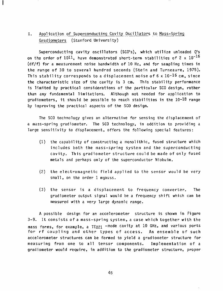
A possible design for an accelerometer structure is shown in Figure 3-9. It consists of a mass-spring system, a case which together with the
mass forms, for example, a TE021 -mode cavity at 10 GHz, and various ports for rf coupling and other types of access. An ensemble of such accelerometer structures can be formed to yield a gradiometer structure for measuring from one to all tensor components. Implementation of a gradiometer would require, in addition to the gradiometer structure, proper
45
TEo2/ -MODE -
CAVITY
UPPER ACCESS
i
-3.S38 dk-
.
-X-BAND WAVE GUIDE
LOWER ACCESS /I
Figure 3-9. A Practical SC0 Accelerometer Design
~~ zg Ll ; :o PC) a :. f+
CAVITY TEMPliRATURE \ N -------- \ \ $2
m-16. ‘. Q(, \
’ .4&p -10” i=;
’ $4 Sa CAVITY POWER \ ye
\ -------mm- \ k? I I 1 I
100 101 102 103 104 105 2
AVERAGING TIME (SECONDS)
Figure 3-10. Predicted Stability of a SC0 Accelerometer
46

mounting of the structure in a spacecraft dewar at low temperature (1.3 K), low-noise microwave oscillator circuits and amplifiers, and frequency measurement equipment.
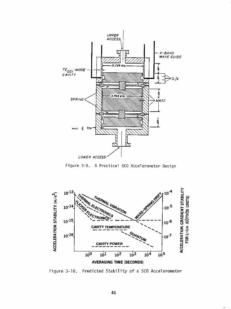
The many sources of noise for such an SC0 gradiometer have been inves- tigated (Turneaure, 1982a, b and Reinhardt et al., 1982. Figure 3-10 shows that a gradiometer with a sense mass of a few kilograms and a baseline of 50 cm, can have a resolution of 10-4 E for a 1 s sampling time. For longer sampling times,the resolution may improve. This estimate of resolution excludes low frequency noise coming from the spacecraft environment.
J. Design Considerations for a Cryogenic Gravity Gradiometer (Sperry Defense Systems)
A design for a cryogenic gravity gradiometer which is based upon proven room temperature noise cancellation and signal enhancement techniques has been developed (Hastings, 1983). The sensor is designed to have a sensitivity of 0.01 E with a one second integration time when operated on an aircraft or other earth based moving vehicles. Minor design modifications could provide 10-J E sensitivity for operation in the more benign noise environment of a satellite.
The conceptual design is presented in Figure 3-11. A levitated balance arm was chosen for the active element of the sensor. Individual accelerometers were ruled out because of the unrealistically large dynamic range requirements for a high sensitivity gradiometer. If the arm is balanced to one micro-gram in a total mass of 100 grams, the common mode acceleration signal is reduced by eight orders of magnitude. The balance arm is passively levitated by persistent currents flowing around the Niobium hub. Coupling of axial vibrations to angular motions of the arm (which occured in the Forward gradiometer) is avoided if the hub and its suspension blocks are relatively large polished disks. In addition, the suspension may be made extremely stiff by using large persistent currents. The balance arm is shown schematically in the figure, and would be constructed to optimize rigidity. For space applications the levitated arm has the advantage that it can be tested on earth.
47

levitated bearing _
piGq = coils
= superconductor
Figure J-11. c ryogenic Gradiometer Conceptual Design
48

Thermal Brownian motion noise of the balance arm is virtually eliminated by the huge Q for angular motions of the levitated arm. In fact,
the system Brownian motion noise gradient is smaller than 10-J E Hz-l/B when up to one Torr of Helium gas is maintained in the system. A few milli-
Torr of Helium gas facilitates heat transfer, thereby assuring the stable levitation of Niobium.
The angular position of the balance arm relative to the cylindrical housing is monitored by sensing the position of one of the rigid Niobium disks at the ends of the arm. When the disk moves, current flows in pancake coils placed at the sides of the disk. The current flows through the input
coil of a d.c. SQUID, thereby converting the balance arm position to a voltage. A position sensitivity of about lo-15 m is required to measure one Hz gravity gradient signals to 3 x 10-J E over a 10 cm baseline. Modern SQUID position sensors can achieve about 10-16 m sensitivity, while room temperature sensors have achieved about lo-10 m. While the requirements of the position sensor scale linearly with the base line dimension of the gradiometer, a small base line instrument is less susceptible to structural changes, and minimizes problems associated with making a finite difference measurement of the gradient.
The SQUID output is amplified and fed to coils around the disk on the opposite end of the arm to provide torque rebalance. Derivative feedback provides nearly noise free damping of-the arm. This insures linear
response, and prevents vibration noise ringing of the high Q mechanical system by lowering the effective Q. Proportional and integral feedback
provide adjustable torque constant and moment of inertia respectively. This creates a potential minimum for the balance arm in which the arm has an adjustable natural frequency. Sperry is currently developing thin film d.c.
SQUIDS and a thin film linear SQUID amplifier with output digitized over the full dynamic range of the amplifier. The expected bandwidth and dynamic range will more than satisfy the needs of the gravity gradiometer. With thin film sense and drive coils, the gradiometer balance arm becomes a small, robust, integrated electromechanical system.
The balance arm is levitated within a cylindrical bearing. The bearing is itself levitated and rotated at a constant angular rate, which provides a
variety of attractive features. Synchronous signal detection at twice the
49

rotation rate provides rejection of acceleration noise (which appears at the
rotation rate). The signal is now detected at a frequency well above the l/f noise region of the SQUIDS. If the natural frequency of the balance arm is adjusted to twice the rotation rate, resonant detection is provided. Finally, the adjustable natural frequency of the balance arm (twice the rotation rate) may be chosen to lie at a particularly quiet point in the vehicle vibration/angular acceleration spectrum. The gradient signal is inductively fed out of the levitated bearing through pancake coils placed at the rotation axis. Small amounts of power for the amplifier (micro-Watts)
are similarly fed into the bearing, although a self-contained cryogenic energy source could be developed for this purpose.
A mechanism for rejection of angular accelerations must be incorporated into a high sensitivity gradiometer (stable platforms cannot reduce angular
acceleration noise to the 10-4 E level). Since the cylindrical bearing responds to angular accelerations but not to gravity gradients, the bearing angular position may be monitored and fed back to the balance arm torque coils to null angular accelerations. This reduces angular acceleration
levels to a manageable dynamic range, and filtering at twice the bearing rotation rate rejects the residual noise.
For operation in the quiet vibration/acceleration environment of a
satellite at the 3 x 10-a E Hz-112 level, the following design modifications are suggested. The rotating bearing which houses the balance arm should be a levitated sphere. The rotating sphere would isolate the balance arm from all but the lowest frequency angular accelerations, and the spin-down rate of the sphere could be monitored to correct the very low frequency data. At intervals of perhaps a day the sphere could be spun to regain tiny losses in
angular rate and to calibrate the sensor. Three spheres aligned along non- colinear axes constitute a tensor gradiometer. The tensor .has three rota- tional invariants, which would serve as output data, thus obviating the need for precise orientation data. Of course, the rotating spheres themselves provide orientation data, although the low rotation rate (probably near five Hz) limits its accuracy. The satellite should be flown with minimum applied torque. Inertial flight requires that the sensors experience the full dynamic range of the vertical Earth field gradient. A fully digitized and accurate dynamic range of ten million should be well within the capability of a SQUID amplifier/digitizer.
50
IV. COMUON PROBLEMS
The problem areas in gravity gradiometer development are sensors, testing, spacecraft and data processing. Within each area, this section discusses important issues and potential solutions. A rational program to achieve the Workshop's overall recommendation “to develop a flight qualified gravity gradiometer for use in the 1990’s on Earth orbit and planetary missions” should follow the remaining recommendations formulated at the Workshop and begin work on each of the problem areas described here.
4
A. Sensors
Although there are many different concepts for gravity gradiometer instruments, there are general sensor problems associated with measurement of gravity gradients as well as problems that are common to either conven- tional, i.e., room temperature, or cryogenic sensors.
1. General Sensor Problems
Sensors must have high sensitivity and wide dynamic range. The sensitivity, as set by the measurement objective, should be on the order of 10-4 E. Some gravity gradient tensor components have a constant bias of about 3000 E. This bias is not needed for recovery of the fine structure of the gravity field. However, when it is present and is measured along with the desired signal, achievement of the stated sensitivity requires a dynamic range of one part in 30 million or one part in 225. A substantial reduction in the dynamic range can be made by measuring a gradient that does not have a constant bias. Such components might have signal at the 100 E level, so a dynamic range of one part in a million would suffice. Sensor linearity and therefore, dynamic range can be enhanced by using force feedback and dif- ferential measurements between accelerometers, although this adds require- ments for balancing and stability of the feedback scale factors.
The simplest instrument is a single sensor that measures one (or two) components of the gravity gradient tensor. This sensor could use an
orientation that reduces the dynamic range requirement or provides some other im.portant benefit. Redundant measurements can be made by an identical sensor in the same orientation. However, a full tensor measurement is often
51

suggested; this requires three sensors with different orientations and the larger dynamic range to obtain five independent components and a sixth that is a redundant piece of information. (The data processing implications of this choice are discussed later in Section 4D). Sensor redundancy for full tensor measurements could be accomplished by duplication of the three sen- sors and their orientations or by addition of one or more sensors with different orientations.
A gravity gradiometer is inherently sensitive,to angular rates; a rate of 3x10⁻⁹ rad/sec produces the same signal as a gradient of 10-4 E. Conse- quently, attitude rates must be controlled or known with high precision in
order to recover the real gravity gradients. Orientation uncertainty can also be a significant source of gravity gradient error; except for certain orientations that are less sensitive to attitude error, an attitude error of 3x10⁻⁷ radians produces a shift of about 10-4 E in the gravity gradient signal. Any instrument can be equipped with an attitude reference system to meet its own requirements. Some instrument concepts for measuring the full tensor can acquire the attitude information with the same sensors used for gravity gradient measurements. Another option is a combination of gravi'ty gradient terms that is attitude invarient, such as the determinantofthe matrix.
Noise reduction is very important because it is fundamental to instru- ment sensitivity. A variety of system design techniques including synchro- nous detection, force feedback, and floated suspensions are known to reduce system noise caused by internal and external sources. The conventional
( i.e., room temperature) systems make extensive use of these techniques. It is inferred that there may also be advantages for gradiometers operating at cryogenic temperatures such as making it easier to test these sensors in the Earth's gravity and meet the stated objective of a 3~10~~ E noise level in a one second integration.
Planetary missions have less demanding measurement requirements and at
the same time cannot offer the support of a spacecraft dedicated to gravity gradient measurements. If the same sensor concept can be used for both Earth and planetary applications, then better planetary data can be obtained than would be possible with tracking and the cost and time associated with the development of an entirely new instrument can be reduced.
52

I -
These general sensor issues are incorporated in a recommendation to “conduct analyses of instrument configurations and mechanizations for optimum performance. These analyses should focus on the following topics:
a.
b.
C.
d.
e.
Dynamic range requirements for spinning and inertial sen- sors in various orientations, especially those that reduce the large constant gravity gradient of about 3000 E.
The relative merits of full tensor measurements and redundant measurements of specific tensor components.
Instruments with an internal inertial navigation capa- bility or a reduced sensitivity to orientation errors.
Incorporation of conventional system techniques for noise reduction (e.g., synchronous detection, force feedback, and floated suspensions) into instruments with cryogenic detectors.
Adaptation of the sensor to planetary missions.
2. Conventional Sensors
Several conventional gravity gradiometers operating at room temperature have demonstrated performance in laboratory testing of about1 E for a 10 second integration period. Increased sensitivity to the 0.01 E level can be projected for larger, space-based sensors. In the existing sensors, gradients are measured over baselines of about 10 cm. Designs with scaled- up dimensions around 100 cm could be attempted and would be up to 10 times more sensitive. Lower noise, and therefore, increased sensitivity, is
expected in orbit because the error sources caused by the Earth's gravity are eliminated. Because of their maturity, these conventional sensors could be used for demonstrating general sensor concepts in the laboratory and on test flights or planetary missions with modest sensitivity goals.
Although some development effort is required to perfect conventional sensors, the Workshop made no specific recommendation for improved understanding of their behavior in zero-gravity.
53
3. Cryogenic Sensors
The predicted sensitivity of gravity gradiometer sensors employing cryogenic technology is at or below the desired measurement goal of 3x10⁻⁴ E for a one second integration. This potential can be realized only if the instrument and spacecraft are designed so that their contributions to the overall measurement error are comparable to or less than that of the cryogenic sensor.
Cryogenic sensors can achieve high sensitivity because of the intrinsic advantages of operating at low temperatures, namely:
1) low thermal noise
2) high mechanical stability 3) low internal dissipation 4) the ability to exploit superconducting and superfluid phenomena
At low temperatures, the thermal coefficient of expansion, thermal resistance and thermal capacity approach zero. Therefore, thermal- mechanical processes responsible for noise, structural deformations and dissipation are expected to be lower at cryogenic temperatures - generally meaning less than 4.2 K, the boiling point of liquid Helium at one
atmosphere - than they are at room temperature. Superconductivity in electrical conductors can be exploited to provide a sensor environment which is uniquely immune to electromagnetic interference. Superfluid helium has extremely high thermal conductivity. This very useful property offers high temperature uniformity.
Either a SQUID or SC0 is capable of measuring the relative position of a proof mass with an accuracy of about lo-15 meters. This precision allows an instrument with a baseline of around 10 cm to have sensitivity of about 3x10⁻⁴ E HZ-I/~. These sensors have wide dynamic ranges and naturally quantized outputs are available via the flux.counting technique for the
SQUID and frequency counting for the SCO.
The Workshop recommended "the development of sensor technologies that contribute to the desired capability. Specific examples are Superconducting
54

Quantum Interference Devices, Superconducting Cavity Oscillators, low temperature preamplifiers, and suspensions for proof masses:
With regard to the SQUID, there is a need for improved pancake coils
used for sensing and controlling the position of the proof mass and for better joints which must carry persistent currents. Thin film technology was suggested as a way to produce coils which are more reliable and rugged, are easily and reliably fabricated, and offer better coupling because of closer mounting to the moving surface. A cryogenic amplifier circuit with less low frequency noise would also be beneficial for SQUID-based sensors. An alternative is a signal modulation scheme that shifts the signal to a higher frequency where the amplifier noise is less. The superconducting coils and SQUID sensor could be created on the same thin film integrated circuit.
The SC0 needs fundamental design studies in cavity and proof mass system fabrication. There is a possibility that the entire structure could be made of fused metals and perhaps only of superconducting Niobium. Monolithic fabrication techniques are an attractive option for higher precision and repeatability. A unique problem for the SC0 is the development of a high-quality, non-contacting microwave choke to prevent losses at the gap between the proof mass and the cavity. The detection of the SC0 frequency shift requires a reference oscillator, a mixing circuit, and a cryogenic microwave amplifier. The development effort should measure the equivalent noise temperature at the operating frequency and the low frequency, multiplicative noise of available amplifiers and, if necessary, modify a design to meet the requirements of a gravity gradiometer sensor.
The active electrostatic suspension used in room temperature accelerom- eters for space applications or a passive magnetic suspension utilizing persistent currents are potential alternatives to the mechanical springs that are now being considered for cryogenic sensors. Either option could provide sufficient levitation force for testing in the laboratory and less force, with less noise, in an orbital system. Since electromagnetic suspen- sions have been developed for room temperature applications, this experience should be valuable in the development of error models and the solutions to noise level problems in a cryogenic system.
55
B. Testing
Testing must be an integral part of the program to develop an advanced gravity gradiometer. Three types of testing were discussed at the Workshop,
namely laboratory testing, determinations of spacecraft environments and an
operational test of an instrument in orbit.
1. Laboratory Testing
Testing in the laboratory is the easiest method of demonstrating sensor
performance. The laboratory environment includes the Earth's gravity which
can cause significant errors not expected in space. Therefore, it may be difficult to test the sensor at the noise level expected in orbit. If the
system has internal navigation aids (i.e., measurements of linear and angular accelerations), the noise limit should be lower and may be at the desired 3x10⁻⁴ E Hz-l/2 level. The effects of the Earth's gravity could be
reduced by special sensor orientations or by using electromagnetic fields, fluids or springs to float the sensor's sensitive parts. There was no general recommendation concerning laboratory testing because it was assumed that laboratory testing would be included in any sensor development effort.
2. Orbital Environment
For the actual gravity gradiometer mission, and for any system test flight, it will be necessary to know the orbital environments prior to the design of the flight equipment. Therefore, the Workshop recommended that an early effort be made to .estimate and eventually obtain actual measurements of important spacecraft environmental parameters, in particular vibration, attitude rates, and temperature stability.' Estimates and measurements are needed for all candidate instrument carriers, including the Shuttle, the TSS and free-flying satellites. The environmental parameters should be deter- mined over the full range of operating altitudes, approximately 100 to 250
km. Several specific flight opportunities were identified, namely the GRM, as an example of a low altitude free-flyer, and the development flights for the TSS. Perhaps a common test package could be developed to measure
environments during these flights as well as other unidentified opportunities similar to potential gravity gradiometer missions.
.
56
I -
The TSS is not a free flyer and this creates unique problems of resi- dual gravity and dynamic noise that must be clearly identified and solved. Inside the subsatellite, gravity is up to 5 percent of the Earth's gravity. The most important source of dynamical noise is the tether itself. Mechani- cal oscillations, both longitudinal and traverse, will propagate up and down the tether, adding to the effectofthe low-frequency pendular motions of the long tether itself. The significant forces acting on the tether are:
1. local gravity field
2. atmospheric drag with air density irregularities that contribute to the dynamical noise
3. electrodynamic forces which are minimized by adopting a dielectric such as Kevlar as the tether material
4. thermal effects on the tether, especially those coinciding with terminator crossings
5. mechanical forces and torques transmitted to the subsatellite by the tether
Analytical efforts are underway now to investigate all these factors.
On the demonstration flight of the TSS facility, instruments should measure the dynamic noise with state-of-the-art precision, namely two accelerometers with a sensitivity of 10-g to lo-10 m/sec2 in the horizontal plane and three gyros with a stability of 5 to 15x10-g rad/sec (1 to 3 x 10m3 degrees per hour). Taking into account the common-mode rejection capabilities of the gradiometer, determination of the dynamic noise on the tethered satellite to this degree of sensitivity should be sufficient.
3. Orbital Test Flight
Given the problems of laboratory testing it is likely that a full system test and operational demonstration will have to be done in orbit. Consequently, there was a desire to “develop an orbital test program that will allow instruments to be tested and calibrated in the actual spacecraft environment.” The test objectives could be accomplished during a single shuttle flight so that the instrument would be recovered and would be available for futher laboratory or space testing. The test facility should
57
contain environmental noise and gravity signal generators to simulate the expected spacecraft environment and to calibrate sensor performance.
The test program could be conducted in the Shuttle cargo.bay, on the
TSS or on a recoverable free-flying satellite. These options are expected
to have diferent environments, costs and support capabilities. The process
of selecting the flight mode involves estimating the environments, proposing methods to ameliorate undesirable environments and then computing the total cost for supporting the instrument and modifying the environment. For the
purpose of defining the development program, the selection of the TSS option is assumed to provide an acceptable environment for a meaningful test with minimum expense.
C. Spacecraft
The spacecraft that carries a gravity gradiometer on an operational mission must have some capabilities that may have been individually
accomplished previously, but not simultaneously. To anticipate the
spacecraft system implications of a gravity gradiometer mission, the Workshop recommended an effort to "analyze problems in the design of the spacecraft systems that are due to requirements for:
a. achieving quiet vibration and attitude rate environments.
b. keeping the sensor at a low altitude using either a propulsion system or a tether.
C. maintaining cryogenic temperatures with dewars or non- mechanical refrigerators (the latter is essential for planetary rissions).'
The requirement for global coverage dictates that the spacecraft be in a polar or near-polar orbit. The spatial resolution goal is most easily met
by operating the instrument at the lowest possible attitude. Coverage and spatial resolution together imply a mission duration of several months to one year. Measurement accuracy is the reason that quiet environments and cryogenic temperatures are desired by the sensor.
58

1. Attitude and Vibration Control
Because gravity gradiometers are intrinsically sensitive to attitude rates and to attitude errors, these instruments can place strong demands on the spacecraft's attitude control systems. Vibration is a concern since it is a coupling mechanism between sensor errors and non-ideal sensor performance. Vibration can also cause attitude errors. For gradiometers with no integral attitude sensors, the attitude rate must be kept below 3x10-g rad/sec (or known with at least that accuracy) in order to have measurements with the desired precision of IO-4 E. For the same reason the uncertainty in the pointing direction should not exceed 3x10⁻⁷ radians. A comparison with the Space Telescope requirement for rms pointing errors of less than 3x10-S radians (0.007 arc set) over a 20 minute observation demonstrates that attitude control requirements for gravity gradiometers are a technical challenge. Given the capabilities of current gyroscopes and, perhaps, the relative insensitivity of some instrument concepts to attitude errors, it is expected that the attitude control problem can be solved.
For spacecraft in low altitude orbits minimizing atmospheric drag and the impact of drag on attitude control are important considerations. A long cylindrical spacecraft, like GRM, has low drag when the axis of the cylinder is parallel to the flight direction. This means that the spacecraft must be rotated once per orbit, or at approximately IO-3 radians per second, about the normal to the orbit plane. It must be determined that the instantaneous attitude and rotation rate of a slowly spinning spacecraft can be measured and controlled with sufficient accuracy.
Because some sensor concepts prefer an inertial orientation while others want a platform rotating at about one radian per second, there should be attempts to define spacecraft control systems that provide these sensor attitudes. An inertial platform or spin bearing could decouple the sensor and spacecraft orientations, yet allow the spacecraft to have a low drag shape and attitude.
The sensor could also be isolated from vibration and non-gravitational accelerations. A "drag free" satellite, again like GRM, has an internal proof mass sheltered from external forces so that it follows a true gravitational orbit as sensors and thrusters make the spacecraft follow the
59

..,.I I I I .111.1. I . . . . . . . . _..--_. ---.. ._-- . -._- __.... _...-...--.
proof mass. The best isolation would be obtained if the gravity gradiometer instrument package were used as the proof mass in the drag free system.
However, a drag free orbit is not required for a gravity gradiometer.
Thus, instead of having the spacecraft constantly following the drag-free instrument package, this package could float freely in a large cavity within the spacecraft. When external forces on the spacecraft cause the package to approach the cavity wall, a magnetic field could be used to repel1 the package by inducing eddy currents in a conducting shell around the package. When the external acceleration is less than 10-J m/set*, the GRM level, a clearance of about 2 cm allows at least a one minute drag-free measurement interval. Repositioning the instrument package can then be done in several seconds and should require only a few watts of electrical power. A further advantage is that, by adding phased coils in the instrument package, the magnetic forces could be used to spin the package at any desired rate and direction.
The recommended studies for attitude control and vibration isolation as described above require rather elaborate and sophisticated spacecraft engineering. However, the Workshop also recommended studies of instrument
concepts that would have an inertial navigation capability and, therefore, reduced requirements. The spacecraft design studies should include a con- cept that is appropriate for this type of instrument.
2. Propulsion and Tether Systems
Because of atmospheric drag, neither the Shuttle nor a typical free- flying satellite can operate easily at altitudes less than 225 km. Lower
altitudes are possible for the TSS and a satellite that has sufficient propulsion capability to overcome drag. The altitude goal would be about
125 km for a tether and 160 km, the same altitude as GRM, for a free flyer.
With TSS, a 500 kg subsatellite with instruments such as a gravity gradiometer , can be operated at up to 100 km from the Shuttle. The first demonstration flight of TSS is scheduled for late 1987 or early 1988; addi- tional flights are planned at 6 to 12 month intervals. There is concern about vibration and attitude control for the TSS; the Workshop's
60
recommendation for a preliminary analyses and measurement of the orbital environment has been discussed earlier.
A propulsion system is needed to overcome atmospheric drag on a free- flying spacecraft at the operating altitude for the gravity gradiometer. The propulsion system would also be used to make transfers between the Shuttle orbit at about 250 km and the operating orbit. The size at the propulsion system is determined by the atmospheric density of the operating altitude, the cross sectional area of the spacecraft, the drag coefficient (shape), and mission time. Note that atmospheric density at a given alti- tude is dependent on the level of solar activity. A period of high solar activity is expected in the early 1990s while a more favorable solar minimum occurs in the late 1990s. The propulsion option to be considered is hot gas vs. cold gas. The liquid Helium used for cryogenic temperature control, a possible cold gas propellant, offers proportional thrusting. This is a very attractive feature when the satellite is "drag-free" and requires continuous, controlled thrusting to minimize drag variations due to the Earth's oblateness, thermal bulge, etc. Because cold gas is less efficient (it has a lower specific impulse), the mass and volume devoted to propellant is larger.
As an example each GRM spacecraft requires about 1000 kg of hydrazine, a hot gas propellant, for a six-month mission at an altitude of 160 km. Two propellant tanks are provided, one at the front and the other at the rear of the long cylindrical spacecraft. Fuel is drawn simultaneously from both tanks so that the center of mass stays at the same location. Similar procedures are also necessary for a gravity gradiometer mission because attitude control is easier and because both have instruments that are sensi- tive to the local mass distribution.
3. Cryogenic Systems
The temperatures required for superconducting instrumentation cannot be provided by simple passive (radiator) systems. One must choose between a stored cryogen system (liquid Helium) or an active refrigeration system. The chief determinants of the choice will be required mission life and tolerable vibration. With existing techniques, Earth or lunar orbiting missions can be done with a stored cryogen system. Planetary missions would
61

not be possible because of the lifetime constraints of a stored cryogen system. For lo.ng lifetime missions including those with a long cruise phase to the body being studied, active refrigerators must be developed. The most suitable candidates are non-mechanical refrigerators and closed-cycle cascade Joule-Thomson refrigerators.
A near one-year lifetime 1.7 K superfluid He system on the Infrared Astronomical Satellite (IRAS) is now operating in a 900 km sun-synchronous orbit. The techniques for handling the cryogen and achieving this lifetime
are now well developed. The Cosmic Background Explorer (COBE) will use the same type or orbit and a modified IRAS dewar. For use on a gravity gradiometer mission the IRAS dewar may need to be modified to support opera- tions in a lower altitude and less thermally favorable orbit and to enclose a cooled instrument rather than a telescope open to space. An improved dewar design is now being developed by NASA that may achieve up to a factor of two improvement in thermal performance.
No suitable space qualified refrigerator is now available to provide
the temperatures required for the superconducting systems and to meet the severe vibrational constraints imposed by a gravity gradiometer. Joule-
Thomson refrigerators with adsorption compressors contain few (if any) moving parts and would be a suitable refrigeration scheme integrated into the dewar because of their very low vibrational noise. An attractive mechanical refrigerator scheme is the closed-cycle cascade Joule-Thomson refrigerator. The refrigerator is very simple (no moving parts or expansion engines) but requires a warm high-pressure compressor which is coupled to
the dewar only through small capillaries. This interfacing to the dewar
should make vibration isolation much simpler.
D. Data Processing
At the Workshop, two data processing problems were identified for research prior to implementation of gravity gradiometer missions. They were: "compute the performance of a gravity gradiometer in low Earth orbit with a system noise level of about 3x10⁻⁴ E in a l-second integration period" and "Simulate the analysis of gravity gradiometer data to validate processing strategies and to anticipate computational problems involved in
62

the downward continuation to meaningful geophysical quantities." Both o f these recommendations concern ground processing o f gravity gradiometer data.
1. On-Board Processing
The gravity gradient measurements will consist o f between one and five independent l i n e a r combinations of the elements of t he g r a v i t y g rad ien t t enso r a t s a t e l l i t e a l t i t u d e . Data wil l be acquired a t about one second i n t e r v a l s . Because o f t he wide dynamic range, about 25 binary b i t s a r e needed t o r ep resen t one of t he combinations. T h u s the g r a v i t y da ta r a t e should not exceed 200 b i t s per second or one million b i t s per o r b i t . These measurements must be accompanied by accurate pos i t i on , time, a t t i tude and a t t i tude rate information. The f o l l o w i n g typical e r ror s ens i t i v i t i e s apply:
a1 t i tude 1 E / k m level a t t i t ude 4x10³ E/radian a t t i t ude rate (per radian/sec
of rotation rate , per ax i s ) 109 E / ( radian/sec)*
The a l t i tude and pos i t i on information can be calculated on the ground us ing accurate values for the o r b i t elements and measurement times or on-board the spacecraft by making use of navigational s a t e l l i t e s . The a t t i t ude data w i l l be used t o v e r i f y performance of t he a t t i t u d e cont ro l system and, i f necessary, t o make c o r r e c t i o n s t o the raw g r a v i t y data. These s u p p o r t i n g measurements approximately double the amount of data tha t must be acquired and transmitted to the ground. Consequently, there i s no real need for on- board data processing. However, i f the a t t i tude corrections must be made much more often than once per second, then i t may be bet ter t o perform these calculations on the spacecraft and transmit only corrected and averaged data a t one second intervals.
2. Ground Processing
Ultimate u t i l i za t ion of a satell i te-borne gradiometer will require the establishment o f a data base o f corrected g r a v i t y gradient measurements a t s a t e l l i t e a l t i tude expressed i n a sui table geodetic datum and one or more o f the fo l lowing derived data bases:
63

o Mean g r a v i t y q u a n t i t i e s (e.g. g r a d i e n t s , anomalies , potent ia ls) on a regularized reference surface (e.g., an e l l ipso id) a t s a t e l l i t e a l t i t ude
o Mean gravity quant i t ies reduced t o the Earth's surface, geoid or appropriate reference e l l ipso id
o P o i n t mass or o t h e r dens i ty d i s t r i b u t i o n models which rep1 icate the measured gradient f i e ld a t a1 titude.
The Workshop's recommendations f o r studies of performance and validation of data processing s t ra teg ies refer specif ical ly t o the creation o f these data bases given the instrument data.
The f i r s t ground processing task is the correction and cal ibrat ion of the raw ins t rument d a t a . A t t h i s t ime the inf luence o f a t t i t u d e and a t t i t ude rate e f fec ts i s removed, d a t a i s converted from instrument units t o real physical units and redundant information i s used to improve estimates of the independent va r i ab le s . This i s a s t r a i g h t f o r w a r d computational process.
Since there i s no general agreement on the most useful representation of the data, techniques should be developed to transform g r a v i t y gradient d a t a i n t o g r a v i t y anomalies and p o t e n t i a l s . I t has been conjec tured t h a t t he u t i l i z a t i o n o f r o t a t i o n a l l y i n v a r i a n t g rad ien t e lement combinations would obviate the need for a t t i t ude and azimuth information. A l t h o u g h such an approach could prove useful for comparisons w i t h upward continued surface g r a v i t y g rad ien t d a t a , knowledge o f a t t i t u d e i s needed t o r e l a t e the gradients to other geopotential quant i t ies .
The s a t e l l i t e gradiometer measurements wil l also require compensation a n d c o r r e c t i o n f o r the f i e l d of nearby masses (mass-induced g rad ien t s e n s i t i v i t y is 0.13 E/kg /m3) and the f i n i t e s i z e of the gradiometer . T h i s l a t t e r e f f ec t , i n t e r r e s t r i a l applications involving a 20 cm instrument a t accuracies near one E, has necessitated consideration of gradient derivative tensors t h r o u g h order eight. The eighth order gradient tensor has dimension seven and conta ins 37 te rms , o f which 15 a r e independent. The number o f
64

gradient derivative terms needed to support the near-field compensation of a satellite gradiometer to 10-Z E or Tess is unknown. The terrestrial instrument, however, is mounted on an inertial platform so that there can be rapid motion of local masses with respect to the instrument. On a spacecraft such motion effects should be much less of a problem.
Data processing for testing and verification require different approaches than for data utilization. The lack of existing gradient data at satellite altitude will require the use of multiple repeat-pass techniques to verify instrument performance and identify errors. Central to this process will be the suppression of signal content and the identification of noise parameters at the 10-j and 10-a E level.
The process of transforming the gradient measurements at altitude into ground level informatioi will necessarily involve downward continuation of one form or another. If orbital altitude preprocessing is limited to removing the effects of oversampling and 100 km resolution is sought, global reduction will require the treatment of 62,800 data items per gradient element utilized. Note that between one and five gradients would be involved. The only known approach which could be applied to such a large data set would be the use of fast Legendre transform spherical harmonic techniques developed by Goldstein (1978), Colombo (1981b) and others. The preprocessing required to provide the necessary block averages on roughly a 100 km cell size would introduce some unnecessary error. (See below.)
An alternative to the global reduction of gradient data (or perhaps parallel to it for comparison purposes) is the use of local processing techniques which treat the measured gradients on a region by region basis. Control of edge effects and maintenance of resolution leads to a two- dimensional moving window (or patch) concept which, at orbital altitude, would have a size near 1000 km by 100 km. Combination of the downward continuation and gravity vector quantity estimation steps appears attractive because the measured gravity gradients' are used as inputs, thereby minimizing data extent required per downward continued point. The smoothing inherent in the estimation process offsets the illconditioning of the downward continuation. The reduction could then be performed suboptimally, using the fast spherical harmonic techniques mentioned above or by stretching conventional least squares collocation approaches. Optimal use
65
of the gradient data would require the relaxation of preprocessing so that data dimensionality is not immediately decreased to goal resolution levels and the use of more advanced algorithms that can accommodate the high dimen- sionality associated with moderate residual oversampling following
preprocessing (Tait, 1982). This leads to additional accuracy not possible when the preprocessing data output is as coarse as the final desired resolu-
tion.
66
V DEVELOPMENT PLAN
The recommendations of the Workshop constitute the critical steps needed to develop a gravity gradiometer instrument and a conceptual design for a Gravity Gradiometer Mission (GGM). This section defines each of the
critical steps, organizes them into a logical sequence, and estimates funding requirements for an advanced development program beginning in FY 1985.
A. Critical Steps
The proposed GGM development plan is divided into three areas: scientific analyses, instrument design and testing, and spacecraft and mission design. Within each area, tasks are described in the order they appear in the workshop recommendations in Section 1.
1. Scientific Analyses
The gravity gradiometer development program needs further scientific justification and support. Therefore, this plan provides for establishment of a user working group and incorporates analyses to better define data reduction procedures.
The continued involvement of scientists in the development program is needed and should be provided by forming a user working group for GGM. The group would have periodic meetings to review technical progress and to study special problems,and would be responsible for assuring that the needs of the scientific community would be met. The group would define the science objectives for GGM, identify important geophysical, geodetic, and oceanographic problems, and establish the corresponding requirement for GGM accuracy. The Workshop on a Dedicated Gravitational Satellite Mission (Harrison and Rapp, Chairmen, November 1978) and its report, titled "Appli- cations of a Dedicated Gravitational Satellite Mission (NRC, 1979), performed this task for GRM. The user working group would be replaced by an Investigator Working Group after GGM is approved.
The initial activity under the data analysis simulation task is a performance calculation for a gravity gradiometer that gives the expected
67
error (not the sensitivity) in the gravitational field (in mgal) or the
geoid height (in cm) as a function of wavelength (in km). Separate calculations should be done for typical continental and ocean areas and for each combination of assumed values for the instrument and system noise levels and orbit altitude. Instrument and system noise levels from lo-2 E to 10-S E in a 1 set integration should be used to represent the most optimistic projections for conventional and advanced cryogenic systems. Orbit altitudes should be varied between 125 and 250 km; the lower value is achievable with the TSS while the upper one is a shuttle-accessible orbit. As part of this activity, GGM performance and scientific need should be evaluated to establish realistic performance requirements in terms of scien- tific objectives.
More detailed data analysis simulations are to be conducted to verify and improve the methods that would be used to reduce instrument and system data. Local or block solutions and global or spherical harmonic methods would be investigated for the downward continuation problem. The alterna-
tives for types of data are scalar potentials, vector components, and tensor components.
2. Instrument Design and Testing
The instrument-related tasks concern the development of new technology
for sensors and the design and testing of proposed instruments. This area requires intensive efforts and is the primary focus of the development program.
The first tasks in this area are sensor concepts and sensor
development. Two types of cryogenic detectors, the SQUID and SCO, have been suggested; each has the sensitivity required for this application. Work on
each type is recommended, including innovative methods of fabrication, such
as low noise preamplifiers and thin film technology for SQUID coils. An- other important sensor development topic is the proof mass suspension. The
suspension is important because it is a likely path for spurious signal coupling to the sensor and because the projected improvements in sensitivity come from scaled-up proof mass dimensions.
68
I -
An instrument options assessment is included to study the integration of the sensor into an instrument, and later into a mission. This task should consider such issues as the number of sensors, sensor orientation, attitude control or knowledge, and incorporation of conventional noise
reduction techniques. Multiple sensors may be used to provide redundant
measurements or full tensor measurement. Some sensor orientations have reduced dynamic range requirements; others are less sensitive to orientation errors. Because gravity gradiometers are inherently sensitive to angular accelerations, attitude control or knowledge is essential. Attitude infor- mation can be provided by a full tensor instrument or by auxiliary sensors
(gyros). Noise reduction techniques that might be applied are force feed- back, synchronous detection, and non-mechanical proof mass suspensions.
An orbital test instrument task is included in the plan so that selected design concepts can be implemented and then subjected to orbital testing. The instruments would be used for laboratory testing and for the test flight.
A test plan will identify procedures and goals for laboratory and orbital testing. Extensive laboratory testing is needed to build confidence in the sensor concept. Sensors must be tested in orbit because they are expected to perform better in the low gravity environment and, in some cases, will only work in a low gravity environment. The test flight may use a modified laboratory sensor, and may have reduced sensitivity.
3. Spacecraft and Mission Design
Spacecraft and mission design for a GGM also has some unique challenges. This development plan provides for completion of Phase A, or conceptual design and Phase B studies, with supporting information provided to the other study areas as required.
A task to estimate environments is needed to provide a more definite basis for assessing spacecraft influences on instrument and system performance. The critical parameters are attitude stability and accuracy and vibration. Separate estimates are needed for each type of spacecraft, i.e., the shuttle, the TSS, and inertially- and spin-stabilized free-flyers.
69

The added complications of atmospheric drag at low altitudes must be included in the estimates.
The Phase A study study should consider several options for spacecraft
types and instrument concepts. Key subsystem problems for this phase are thermal, attitude and orbit control. An orbital,test systems activity is needed to suport the orbital test of instrument performance. The plan assumes that the orbital testing is performed with the TSS or perhaps with STS recovered free-flyers (e.g., Spartan), a preliminary flight of the GGM spacecraft, or Spacelab. The Phase B study should focus on the preferred spacecraft and instrument concepts and should produce concepts for all subsystems and a firm estimate of mission costs.
B. Development Schedule
The development schedule for the GGM is shown in Figure 5-l. Also shown are decision points where specific actions are required to continue
the development plan. It is assumed that the development program is funded in FY 1985 and that GGM is approved in FY 1992 for launch in 1996. The projected schedule follows that of the GRM, by about four years; namely approval in FY 1988 for a 1992 launch.
Some key activities need to be continued or initiated prior to the start of the development program. During 1983 and 1984, on-going sensor development, testing and spacecraft studies should be supported at the
University of Maryland, Smithsonian Astrophysical Observatory and Goddard Space Flight Center. Assuming FY 1985 funding, the user working group
should be established in 1985. The definition of science objectives and the performance calculations should be completed in 1985. Spacecraft environmental studies will be initiated in 1984 using available data and would be completed in 1986. These studies will provide specifications for the GGM spacecraft.
Principal emphasis of the program will be on sensor concepts and in- strument development. These activities will be intensified and expanded,
beginning in 1985, to support needed sensor developments and tests leading to an orbital test flight and selection of a GGM in 1990.
70

CY 94 95 99 97 99 99 90 91
SCIENTIFIC ANALYSIS
0 DATA SIMULATION T7
0 USER WORKING GROUP \7
INSTRUMENT DESIGN 88
b TEST
0 SENSOR CONCEPTS I V
0 SENSOR DEVELOPMENT V
0 INSTRUMENT OPTIONS V
0 ORBITAL TEST INSTRUMENT V
SPACECRAFT AND MISSION DESIGN
0 ESTIMATE ENVIRONMENTS
0 PHASE A STUDY
0 ORBITAL TEST SYSTEMS
0 PHASE B STUDY
GGM DECISION POINTS
v
V DEVELOPMENT
FLIGHT V
V
0 ORBITAL TEST APPROVAL A
0 PHASE 6 APPROVAL A
0 A0 RELEASE 11
0 INSTRUMENT SELECTION A
0 NEW START APPROVAL c
FIGURE 5-1. GRAVITY GRADIOMETER DEVELOPMENT SCHEDULE.
71
Concurrent with the instrument activities, an orbital test flight is planned in 1990 (1986 decision point), to verify general instrument perfor- mance and operation , and to support the new start decision process. For the purpose of these tests, the instrument concept will be chosen on the basis
of readiness for flight.
The Phase B mission study will be completed and a firm instrument design will be selected prior to the FY 1992 new start for the GGM.
C. Cost Considerations
A preliminary cost estimate is given in Table 5-l. The instrument design and development assumes that only two instrument concepts are pursued. The orbital test flight assumes use of the TSS, and upgrade of a laboratory-quality instrument.
These estimates have been structured to provide for Phase A and B study
efforts, and to firmly establish the technical feasibility and design adequacy of the GGM.
72
TABLE 5-l
COST ESTIMATE FOR GGM DEVELOPMENT PROGRAM
(In FY '84 $M)
Total --~_. _ Fiscal Year Cost
Ta_sk _. _ . i _~._1 _~CG--1984"8L-- 1986 1987 1988 1989 1990 1991
Data Analysis Simulation Working Group
Science Subtotal
Sensor Concepts 0.1 Sensor Development 2.0 Instrument Options 0.3 Orbital Test Instrument 2 5 A Instrument Subtotal 4.9
Estimate Environments 0.2 Phase A Study 1.0 Orbital Test'Systems 11.0 Phase B Study 3.0 Mission Subtotal 15.2
0.5 38 A 4.3
0.1
0.1
0.1
0.2
0.3
0.2 0.2 0.1 0.2 0.6 0.6
0.4 0.8 0.7
0.1
0.6 0.6
0.3 0.4
0.7
0.1
0.1
0.2
0.9
0.1
0.8 1.2
0.8 2.5
0.1 3.3
0.6 0.6 0.6 0.6
0.6 0.6 0.6 0.6
0.4
1.2 77
0.2 4.5
0.5 0.5
2.5 1.4 A 15 - 1.5 2.9 1.5
3.5 z- Program Total 24.4 0.4 1.3 1.8 5.2
4.7
6.9
2.5
3.6
*Preprogram costs shwon for 1984 are not included in the total cost.
73

,
REFERENCES
Breakwell, J.V. (1980), "More About Satellite Determination of Short Wavelength Gravity Variations," Gravsat User Working Group.
Columbo, O.C. (1981a), "Global Geopotential Modeling from Satellite-to- Satellite Tracking," Ohio State University, Report No. 317.
Columbo, O.C. (198lb), "Numerical Methods for Harmonic Analysis on the Sphere," Ohio State University, Report No. AFGL-TR-81-0038.
Forward, R.L., et al. (1973), "Development of a Rotating Gravity Gradi- ometer for Earth Orbit Applications," Final Report, NASA Contract' No. NAS l-10945, NASA CR-11215.
Forward, R.L., et al. (1976), "Rotating Gravity Gradiometer Study," Final Report, JPL Contract 954309, NASA CR 149800.
Forward, R.L. (1979), "Electronic Cooling of Resonant Gravity Gradiome- ters , ” J. Appl. Physics 50, l-6.
Gerber, M.A. (1978), "Gravity Gradiometry - Something New in Inertial Navigation," Astronautics and Aeronautics 16, 18-26 (May).
Goldstein, J.D. (1978), "Application of Fourier Techniques to the Computa- tion of Spherical Harmonic Coefficients," The Analytic Sciences Corporation, Report No. TIM-868-3.
Grossi, M.D. (1981), "Application of Gravity Wave Astronomy Techniques to High Sensitivity Earth Gradiometry," Final Report on NASA-CORE Grant NSG 7176, Smithsonian Astrophysical Observatory.
Hastings, R. (1983), "Design Considerations for a Mobile, High Sensitivity, Cryogenic Gravity Gradiometer,' Sperry Defense Systems, Report No. PX14015.
Lerch, F.J., et al., (1977), "Gravity Model Improvement using GEOS-3," GSFC Document X-921-77-246.
Lerch, F.J., et al. (1979), "Gravity Model Improvement using GEOS-3: GEM-9 and -10," J. Geophys. Res. B. 84, 3897-3916.
Lerch, F.J., et al. (1981), "Goddard Earth Model for Oceanographic Applica- tions (GEM-1OB and -lOC),ll Marine Geodesy 5, 145-187.
Metzger, E.H., et al. (1976), "Satellite Borne Gravity Gradiometer Study," Final Report, NASA Contract No. NAS 5-20910, Bell Aerospace/Textron Report No. 6413-9500001.
NRC (1979), "Applications of a Dedicated Gravitational Satellite Mission," National Academy of Sciences.
Paik, H.J. (1976), "Superconducting Tunable Diaphragm Transducer for Sensitive Acceleration Measurements," J. App. Phys. 47, 1168-1178.
75

.
Paik, H.J. (1981a), “’ Superconducting Tensor Gravity Gradiometer for Satellite Geodesy and Inertial Navigation," J. Astronaut. Sci. 29, 1-18.
Paik, H.J. (1981b), Geod. 55, 370-381.
"'Superconducting Tensor Gravity Gradiometer," Bull.
Ray, J.C., et al. (1982), "Attitude and Translation Control of a Low- altitude Gravsat," 1416.
AIAA/AAS Astrodynamics Conference, Paper No. AIAA-82-
Reinhardt, V.S., et al. (1982), "A Supersensitive Accelerometer for Spacecraft Gradiometry," Proc. IEEE Position, Location and Navigation Symposium.
Stein, S.R. and J.P. Turneaure (1975), "Superconducting Cavity Stabilized Oscillator with Improved Frequency Stability," IEEE Proc. Letters 63, 1249.
Tait, K.S. (1982), "A Generalized Fast Estimation Algorithm for Geodetic Applications," The Analytic Sciences Corporation, Report No. TR-1946-7.
Trageser, M.B. (1975), "Feasibility Model Gravity Gradiometer Test Results," Report P-179, The Charles Stark Draper Laboratory, Inc.
Trageser, M.B. (1970), "A Gradiometer System for Gravity Anomaly Surveying," Report R-588, The Charles Stark Draper Laboratory, Inc.
Turneaure, J.P. (1982a), "Technical Report on the Application of Superconducting Cavity Oscillators to Accelerometers," Bendix Field Engineering Report prepared under NASA Contract.
Turneaure, J.P. (1982b), "Evaluative Report on the Application of Supercon- ducting Cavity Oscillators to a Gravitational Gradiometer," Bendix Field Engineering Report prepared under NASA Contract.
von Bun, F.O., et al. (1980), "Determination of 5O by 5O Gravity Anomalies using Satellite-to-Satellite Tracking using ATS-6 and Apollo," Geophys. J. Roy. Astron. Sot. 61, 645-658.
Wells, W.C., ed. (1981), "Gravity Gradiometers and the POLO Mission," Summary of a Workshop at NASA Headquarters, Science Applications, Inc.
Wells, W.C. (1981), "Lunar Gravity Gradiometers - An Assessment of Feasi- bility and Development Requirements," Science Applications, Inc. Report No. l-120-937-s13.
76
1. Report No.
NASA CP-2305 2. Government Accession No. 3. Recipient’s Catalog No.
4. Title and Subtitle
Spaceborne Gravity Gradiometers
5. Report Date
March 1984 6. Performing Organization Code
7. Author(s)
William C. Wells, Editor
8. Performing Organization Report No.
10. Work Unit No.
9. Performing Organization Name and Address
Science Applications, Inc. P.O. Box 1303 McLean, VA 22102
12. Sponsoring Agency Name and Address
Geodynamics Branch Office of Space Science and Applications National Aeronautics and Space Administration Washington, DC 20546
15. Supplementary Notes
11. Contract or Grant No.
NASW-3622
13. Type of Report and Period Covered
Conference Publication 14. Sponsoring Agency Code
16. Abstract
The Spaceborne Gravity Gradiometer Workshop was held at the NASA Goddard Space Flight Center in Greenbelt, Maryland on February 28 through March 2, 1983. The Workshop was sponsored by the NASA Office of Space Science and Applications and was intended to provide information for the planning of the NASA Geodynamics Program, specifically with reference to a gravity gradiometer mission in the mid 1990s. The presentations and discussions reviewed and assessed the current status of gravity gradiometers. The technical problems and potential solutions were identified. The results of the Workshop became the basis of a long-term plan for the development of orbital gravity gradiometers.
7. Key Words (Suggested by Author(s)) 18. Distribution Statement
Geophysics, Geodynamics, Earth Gravity Unclassified - Unlimited Field, Gravity Gradiometer, Global Gravity Survey
Subject Category 42
9. Security Classif. (of this report)
Unclassified 20. Security Classif. (of this page)
Unclassified 21. No. of Pages 22. Price
86 A04
For sale by the National Technical Information Service, SpinEfield, Virginia 22161 NASA-Langley, 1984