Embed Size (px)
Citation preview

16
Narrowband Interference Suppression in MIMO Systems
Vladimir Poulkov, Miglen Ovtcharov, Georgi Iliev and Zlatka Nikolova Technical University of Sofia
Bulgaria
1. Introduction
Multiple Input Multiple Output (MIMO) communication technology has received recently significant attention triggered by the rapid development of Orthogonal Frequency Division Multiplexing (OFDM) broad-band wireless and high speed wireline communication systems. Such systems are very sensitive to Narrowband Interferences (NBI) due to their relatively low transmission power. This type of signal interference can be found in the new unlicensed frequency bands, e.g., the Industrial Scientific Medical (ISM) band, coming from systems such as Bluetooth or microwave ovens which interfere with OFDM based Wireless Local Area Networks (WLAN), like Hiperlan II. Other examples of NBI, typical for Digital Subscriber Line (DSL) communications, are strong Radio Frequency Interferences (RFI) from short-wave radio, Citizen's Band (CB) radio and amateur “ham” radio which interfere with Hybrid Fiber Coaxial (HFC) networks and high speed DSL. Ineffective shielding of a cable network may also cause the ingress from external home electrical devices, such as cordless phones, TVs and computers. Let’s consider a strong NBI signal which resides within the same frequency band as a wideband OFDM signal. In this case, severe Signal to Noise Ratio (SNR) degradation is likely to occur across all OFDM subcarriers due to spectral leakage of the NBI signal from block processing in the OFDM receiver. In Fig. 1, the magnitude-squared of the received
signal samples 2
[ ]X k is plotted. For flat-fading channels it is straightforward to ascertain
the fact that the highest peak corresponds to the subcarrier affected by NBI, as shown in Fig. 1.(a). Fig.1.(b) shows that in frequency-selective channels the OFDM signal presents a large dynamic range, and some signal peaks can have values close to the peak induced by NBI. This observation indicates that the detection of NBI becomes difficult in frequency-selective channels, especially if the Signal to Interference Ratio (SIR) is high (Giorgetti et al., 2005). The presence of strong NBI causes nonlinear distortion in Automatic Gain Control and Analog to Digital Converter functional blocks as well as spectral leakage in the Discrete Fourier Transform (DFT) process. Many subcarriers close to the interference frequency will suffer serious Signal to Noise Ratio (SNR) degradation. Therefore, NBI suppression is of primary importance. The issue of NBI suppression for OFDM systems has been studied extensively in recent years, and a number of general approaches are proposed. Various Frequency Excision methods, where the affected frequency bins of the OFDM symbol are excised or their usage
www.intechopen.com

MIMO Systems, Theory and Applications
368
avoided, have received specific attention. Often degradation in an OFDM based receiver is beyond the reach of the frequency excision method when the SIR is less than 0dB. In such cases other approaches, related to the Cancellation techniques that aim the elimination or mitigation of the effect of the NBI on the received OFDM signal, are recommended. Linear and Nonlinear filtering methods for NBI cancellation are also proposed.
Fig. 1. The magnitude-squared of FFT bins: |X[k]|2
Different specific approaches for NBI suppression are deployed in MIMO systems depending on the type of channel. For wireless channels one major group of methods is Block Coding (BC): Space Time and Space Frequency. It utilizes the properties of MIMO systems over fading channels. Other methods such as adaptive beam-forming of the MIMO antenna system and Forward Precoding at the transmission side are reviewed. In wire-line subscriber systems methods such as Dynamic Spectrum Management (Level 3), Optimal Precoding and Multi-channel Adaptive Filtering are applied. In this chapter the major NBI suppression methods their performance, computational complexity and application to different types of MIMO communication systems are considered. Results of simulation experiments for wireless MIMO systems and for MIMO DSL channels are analyzed. It could be seen that the methods have different computational complexity and performance depending on the parameters of the MIMO system and the communication channels.
2. Overview of NBI suppression methods
2.1 Frequency excision
This approach uses the Fast Fourier Transform (FFT) based frequency-domain excision to
remove the NBI. The DFT output of block of FFTN samples, ,m nr is given by:
2 /, ,
1
, 1,....FFT
FFT
Nj kn N
m n m kk
r r e k NFFTπ−
== =∑ (1)
where m is the number of the OFDM symbol, n is the number of the subcarrier of the OFDM
symbol, ,m kr is the digital complex baseband signal sample at the demodulator input for m.
www.intechopen.com

Narrowband Interference Suppression in MIMO Systems
369
In the frequency domain, the NBI manifests itself as a peak in the spectra. Interferences can be excised by comparing and limiting the magnitude of each frequency bin to a threshold. The following method is used to determine the threshold. The mean value of the amplitude of the frequency bins and its variance are computed (Jyh-Ching et al., 2004):
10 ,
mean1
10logFFTNm n
FFTn
rT
N== ∑ (2)
( ) ( )2 2
var 10 , 10 ,1 1
1 110log 10log
FFT FFTN N
m n m nFFT FFTn n
T r rN N= =
⎡ ⎤⎛ ⎞⎢ ⎥= − ⎜ ⎟⎜ ⎟⎢ ⎥⎝ ⎠⎢ ⎥⎣ ⎦∑ ∑ . (3)
The threshold is determined according to:
1/2excision mean varT T Tα= − . (4)
The scale factor α in the above equation is adjusted to maintain the threshold at some value of the noise floor. Each frequency bin is compared to the threshold and, if it exceeds the threshold, its value is held at the threshold. After the application of Inverse Fast Fourier Transform (IFFT), the signal is much less contaminated with narrow band interferences. This method is characterized with relative high efficiency due to the fact that the FFT/IFFT digital signal processing could be realized in real time. In addition, it is possible to excise multiple NBIs without any initial limiting conditions. Drawbacks of this method are the impossibility to fully suppress the interference signals because of the NBI interference with the information subcarriers thus violating their orthogonality and the strong dependence of the threshold on the type and conditions of the channel.
2.2 Frequency identification and cancellation The discrete complex baseband signal for sample k at the input of an OFDM receiver can be expressed as (Baccareli et al., 2002):
( ) ( ) * ( ) ( ) ( )t nr k s k h k n k i k= + + , (5)
where ( )ts k is the complex output signal for sample k of the transmitter, ( )h k is the
complex impulse response for sample k of the channel, ( )n k is the complex Additive White
Gaussian Noise (AWGN) for sample k and ( )ni k is n-th complex single tone NBI for sample
k. Initially the frequency position of the interference tone has to be estimated in order to
approach the problem of NBI identification. After sampling the received signal ( )r t to
obtain ( )r k , FFT must be applied to this sequence via a Goertzel algorithm or using a
butterfly lattice. It is important to note that appropriate setting of the sampling time T is a
fundamental step; therefore, to increase the frequency resolution, an eight times
oversampling in the frequency domain is proposed. Assuming that the power spectrum properties of all signals constituting r(k) are known, the narrow band interfering signal can be modeled as a complex sinusoidal tone:
( )/( ) cos( / ) sin( / )n nj k T
n n n n n n n ni k e k T j k Tω ϕα α ω ϕ α ω ϕ+= = + + +& & &
. (6)
www.intechopen.com

MIMO Systems, Theory and Applications
370
( ) cos( / ) sin( / )n n n n ni k a k T jb k Tω ω= +& &. (7)
Thus, it is clear that frequency domain processing is an appealing approach to estimate
frequency, because the spectral properties of ( )r k are known. This method is implemented in several steps. First the complex NBI frequency is estimated by finding the maximum amplitude in the oversampled signal spectrum:
arg max( ( ))n RL Pω ω ω∞= ∈&. (8)
Then amplitude and phase estimation is done. A matrix form can be used to represent the sampled interference (Baccareli et al., 2002):
=ni M x . (9)
The matrix M is defined as:
1 1
2 2
cos( / ) sin( / )
cos( / ) sin( / )
....... .......
cos( / ) sin( / )
n n
n n
n N n N
k T j k T
k T j k T
k T j k T
ω ωω ωω ω
⎡ ⎤⎢ ⎥⎢ ⎥= ⎢ ⎥⎢ ⎥⎢ ⎥⎣ ⎦M
& && &
& &. (10)
The vector x gathers the coefficients na and nb :
n
n
a
b
⎡ ⎤= ⎢ ⎥⎣ ⎦x . (11)
And in is a column vector of the n-th complex NBI where N is the FFT length.
1 2( ) ( ) ( )T
n Ni k i k i k= ⎡ ⎤⎣ ⎦i A . (12)
Applying the Maximum Likelihood (ML) algorithm, the solution is given by (Iltis & Milstein, 1985):
( )−= 1T Tx M M M r
&. (13)
Here r is the input signal vector and x&
is the estimation of the complex amplitude of the n-
th complex NBI. The next step is to estimate the exact values of the amplitude, frequency and phase of each of the harmonic interference signals. The algorithm uses the estimation results from the first step as initial conditions of a Normalized Least Squares (NLS) optimization procedure (Baccareli et al., 2002). The cancellation of the NBI is the last step. The identified frequency, amplitude and phase of the interference in the received signal are used for the synthesis of complex harmonic signals, which are subtracted from the received signal:
( )/
1
( ) ( ) n n
Mj k T
nn
r k r k eω ϕα +
== −∑ , (14)
where ŕ(k) is the input signal for the OFDM demodulator after the NBI cancellation.
www.intechopen.com
Narrowband Interference Suppression in MIMO Systems
371
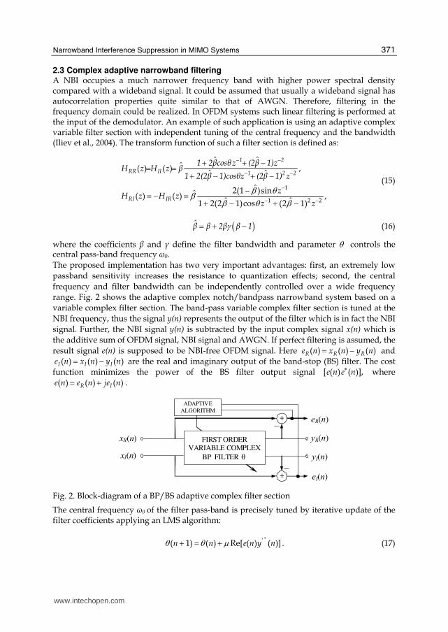
2.3 Complex adaptive narrowband filtering A NBI occupies a much narrower frequency band with higher power spectral density compared with a wideband signal. It could be assumed that usually a wideband signal has autocorrelation properties quite similar to that of AWGN. Therefore, filtering in the frequency domain could be realized. In OFDM systems such linear filtering is performed at the input of the demodulator. An example of such application is using an adaptive complex variable filter section with independent tuning of the central frequency and the bandwidth (Iliev et al., 2004). The transform function of such a filter section is defined as:
1
1 2 2
ˆ ˆˆ( ) ( ) ,
ˆ ˆ
ˆ2(1 )sinˆ( ) ( ) ,ˆ ˆ1 2(2 1)cos (2 1)
1 2
RR II 1 2 2
RI IR
1 2┚cosθz (2┚ 1)zH z H z ┚
1 2(2┚ 1)cosθz (2┚ 1) z
zH z H z
z z
β θβ β θ β
− −− −
−− −
+ + −= = + − + −−= − = + − + −
(15)
( )┚̂ ┚ 2┚ ┚ 1γ= + − (16)
where the coefficients ┚ and ┛ define the filter bandwidth and parameter θ controls the central pass-band frequency ω0.
The proposed implementation has two very important advantages: first, an extremely low
passband sensitivity increases the resistance to quantization effects; second, the central
frequency and filter bandwidth can be independently controlled over a wide frequency
range. Fig. 2 shows the adaptive complex notch/bandpass narrowband system based on a
variable complex filter section. The band-pass variable complex filter section is tuned at the
NBI frequency, thus the signal y(n) represents the output of the filter which is in fact the NBI
signal. Further, the NBI signal y(n) is subtracted by the input complex signal x(n) which is
the additive sum of OFDM signal, NBI signal and AWGN. If perfect filtering is assumed, the
result signal e(n) is supposed to be NBI-free OFDM signal. Here ( ) ( ) ( )R R Re n x n y n= − and
( ) ( ) ( )I I Ie n x n y n= − are the real and imaginary output of the band-stop (BS) filter. The cost
function minimizes the power of the BS filter output signal [ ( ) ( )],e n e n∗ where
( ) ( ) ( )R Ie n e n je n= + .
FIRST ORDER
VARIABLE COMPLEX
BP FILTER θ
ADAPTIVE
ALGORITHM
xR(n)
+
+
xI(n)
eR(n)
yI(n)
yR(n)
eI(n)
Fig. 2. Block-diagram of a BP/BS adaptive complex filter section
The central frequency ω0 of the filter pass-band is precisely tuned by iterative update of the filter coefficients applying an LMS algorithm:
'( 1) ( ) Re[ ( ) ( )]n n e n y nθ θ μ ∗+ = + . (17)
www.intechopen.com

MIMO Systems, Theory and Applications
372
Here ┤ is the step size controlling the speed of convergence, (*) denotes complex-conjugate, ( )'y n is the derivative of ( ) ( ) ( )R Iy n y n jy n= + with respect to the coefficient subject of
adaptation.
2.4 Nonlinear filtering Nowadays communication systems work in a saturated and noisy electromagnetic spectrum. Many of the interference signals could be approximated as independent stationary random processes with Gaussian distribution, but quite a lot of the radio-frequency interferences do not fit into this category. A big variety of impulse noises, to which OFDM systems are quite sensitive, could not be considered as Gaussian and/or stationary random processes. The system model has to take that into account to realize an effective NBI suppression. Under the above conditions nonlinear filtering methods, such as the two considered below, offer an improvement in NBI suppression. a. Nonlinear ACM filter for autoregressive interference
Lets consider the received sampled signal from equation (8). In complex form the
narrowband interference { }ki is modeled as an autoregressive Gaussian process of order p,
i.e., assuming a model of the form (Hsu & Giordano, 1978), (Iltis & Milstein, 1985):
0
k
p
k i i ki
i i eφ −== +∑ , (18)
where { }ke is a white Gaussian process, and where the autoregressive parameters
1 2, , , pΦ Φ Φ… are known to the receiver. Under this model, the received signal has a state
space representation as follows:
1k k kx x w−= Φ + , (19)
k k k kz Hx s n= + + , (20)
1 1...T
k k k k px i i i− − +⎡ ⎤= ⎣ ⎦ , 1 0 ... 0T
kH = ⎡ ⎤⎣ ⎦ , 0 .... 0T
k kw e⎡ ⎤= ⎣ ⎦ , (21)
1 2 1...
1 0 ... 0 0
... ... ... ... ...
0 0 ... 1 0
p pφ φ φ φ−⎡ ⎤⎢ ⎥⎢ ⎥Φ = ⎢ ⎥⎢ ⎥⎢ ⎥⎣ ⎦. (22)
The first component of the state vector kx is the interference ki . Hence, by estimating the
state, an estimate of the interference which can be subtracted from the received signal to
reject the interference, can be obtained.
In (Masreliez, 1975) an Approximate Conditional Mean (ACM) filter for estimating the state
of a linear system with Gaussian noise and non-Gaussian measurement noise is developed.
The nature of the nonlinearity is determined by the probability density of the observed
noise. Under this assumption, the filtered estimate and its conditional covariance kP and
kx&
are obtained recursively through the equations for state (23,24) and time (25) estimation:
www.intechopen.com

Narrowband Interference Suppression in MIMO Systems
373
( )Tk k k k k kP M M H G z HM= − , (23)
( )Tk k k k kx x M H g z= +&
, (24)
1T
k k kM P Q+ = Φ Φ + ; 1k kx x+ = Φ &. (25)
Here Gk and gk are the nonlinear components due to the non-Gaussian noise, εk is the error signal and σ its variance defined by the following equations (Laster & Reed, 1997):
{ }EkQ = Tk kw w , (26)
2 2
1( ) tanh ,k
k k kg zεεσ σ
⎡ ⎤⎛ ⎞= −⎢ ⎥⎜ ⎟⎝ ⎠⎣ ⎦ (27)
22 2 2
1 1( ) 1 sech ,k
k kG zε
σ σ σ⎡ ⎤⎛ ⎞= −⎢ ⎥⎜ ⎟⎝ ⎠⎣ ⎦ (28)
k kε x −= kH x , (29)
2 2nσ σ= + T
kHM H , (30)
The ACM filter here is seen to have a structure similar to that of Kalman - Bucy filter, as the time-update equations (23), (24) are identical. Without the nonlinear functions tanh and sech the recursive algorithm of Masreliez is reduced to the linear Kalman – Bucy algorithm (Sampei 1997). From equations (24), (27) and (29) follows, that with the ACM filter the decision feedback is realized via the function tanh, by correcting the measured value in the interval [-1, 1]. The behavior of the filter depends on the variance of the error signal. When the system is in a steady state, the variance is small and the nonlinear element in the feedback determines the behavior of the filter. When the variance is high, the feedback is in a linear working state and the behavior is similar to that of a linear Kalman-Bucy filter. b. Adaptive nonlinear filter based on LMS algorithm It has been shown in (Sampei 1997) that better interference rejection can be obtained by using one or two-sided interpolation filter. For such a filter the following Widrow Least Mean Squared (LMS) algorithm equations hold (Iltis & Milstein, 1985) (Johnson 1984):
1 1 1, , ... , , ,...,T
k k N k N k k k NX z z z z z+ + − + − −= ⎡ ⎤⎣ ⎦ , (31)
1 1 1( ), ( ), ... , ( ), ( ),..., ( )T
k N N Na k a k a k a k a kθ − − + −= ⎡ ⎤⎣ ⎦ , (32)
where 2N + 1 is the length of the data window. In order to ensure independence of the parameter µ (for control of the stability and convergence of the algorithm) from the input signal level the equations are normalized as follows (Johnson 1984):
1o
k k k kk
Xr
μθ θ ξ−= + , (33)
www.intechopen.com

MIMO Systems, Theory and Applications
374
Where rK is the estimate of the power of the input signal determined as
2
1 1k k o k kr r X rμ ⎡ ⎤⎢ ⎥− −⎢ ⎥⎣ ⎦= + − . (34)
The output signal of the filter εK, which is the error signal is defined as:
,k k kz zε = − & (35)
where žК is the predicted value of the NBI on the basis of L samples from the input signal zK.
By transforming the prediction error a nonlinear transversal filter for the prediction of kz is
obtained. The differential equation of the filter is in the form (Johnson 1984):
( )1 10
( 1)L
k i k i k ki
z a k z ρ ξ− − −== − +⎡ ⎤⎣ ⎦∑& &
, (36)
( )2
tanh kk k k
k
ξρ ξ ξ σ⎛ ⎞= − ⎜ ⎟⎜ ⎟⎝ ⎠ . (37)
Here ρk is a nonlinear function as the one used in equation (30) and σk variance of a Gaussian random variable.
Fig. 3. One-sided Adaptive Nonlinear Filter Based on LMS Algorithm.
A block scheme of an one-sided nonlinear adaptive filter, based on LMS algorithm is shown on Fig.3. For the realization of the filter from equation (36) an estimation of σk and the tap weight coefficients ai(k), has to be obtained using LMS algorithm (Carlemalm et al., 2004).
3. NBI suppression in wireless MIMO OFDM systems
Following some of the specific methods for NBI suppression in MIMO communication systems are discussed, such as adaptive beamforming of the antenna system, forward precoding at the transmission side and Orthogonal Space-Time Block Coding.
3.1 Adaptive beamforming of the MIMO antenna system One of the fastest developing methods for noise suppression in modern MIMO communication systems is employing adaptive antenna arrays in the transmit and receive
zk ρk
+
a1(k)
εk T
źk T T
a2(k) aL(k)
źk-1 źk-2 źk-L
žk
Signal + NBI + AWGN
Signal’ + AWGN’
+ +
εk
žkžk
+
Х Х Х
www.intechopen.com

Narrowband Interference Suppression in MIMO Systems
375
side of the radio-communication system. A block scheme of an MIMO OFDM system with adaptive beamforming is shown in Fig.4, where R is the number of transmit antennas, М – number of receive antennas, N – number of subcarriers in the OFDM symbol, sk(t) 0 ≤ k < N is the k transmitted normalized information symbol from block ‘t’ (Iserte et al., 2001).
Fig. 4. Block diagram of MIMO OFDM communication system with adaptive beamforming.
The control of the antenna array in the transmit side is done via a number of vectors
bk = [b1(k) b2(k)…bR(k)]T, with which the corresponding information symbols are multiplied
before the process of OFDM modulation. In the receive side after OFDM demodulation the
FFT demodulated information symbols yk(m)(t) for each subcarrier k, are multiplied with a
number of vectors for control of the antenna array аk = [а1(k) а2(k)…аM(k)]T за L ≥ Nt (Thung
et al., 2001):
( ) ( ) ( ) ( ) ( )kt t k s t t= = +H H Hk k k k k k kr a y a H b a n , (38)
where H(k) is the matrix of the frequency response of the MIMO radio-channel, nk(t) is the
vector sum of NBI and AWGN, rk(t) is the signal at the output of the control block of the
antenna array of the receiver for the k-th carrier frequency. It is assumed that all the MIMO
channel state information (CSI) is available at the transmitter, including the statistical
characteristics of the narrowband and wideband noises. The maximum of the signal-to-noise
plus NBI is obtained when the receiver has characteristics equal to a matched filter in
relation to the communication channel (Wong et al., 2001), (Iserte et al., 2001):
( ) ( )k MAX kSNIR k kα −⇔ = 1k n ka R H b , (39)
where { }( ) ( ) ( )k E t t= Hn k kR n n is the covariance addition matrix of the NBI and AWGN.
www.intechopen.com

MIMO Systems, Theory and Applications
376
In the real systems there are limits for the total emitted power from all of the antennas. For
MIMO OFDM systems with adaptive beamforming of the transmission antenna system the
emitted power from all of the antennas for the k-th subcarrier is proportional to ║bk║2. The
goal of the optimization procedure is to find an optimal vector with emitted power weight
coefficients - bk for each antenna:
( )2 2( ) ( ) ( )MIN kJ k SNIR k kλ β= − −kb , (40)
where λ(k) are the eigenvalues, │┚(k)│2 is limit of the emitted power from all antennas.
3.2 NBI suppression with low-complexity precoding at the transmit side Methods based on forward precoding of the signal at the transmission side assume that the
wireless channel characteristics (narrowband and wideband noises included) are known in
advance at the transmission side. One recently proposed method of low computational
complexity is precoding at the transmit side with maximizing the diversity of the received
signals, Fig.5 (Rico et al., 2007).
Fig. 5. Block diagram of MIMO OFDM communication system with forward precoding
This approach uses the information about the type of the transmitted symbols as criteria for
the selection of optimal precoding matrix. The signal at the input of the receiver side is
given as:
= +y HT x n (41)
where y is the vector [nr x 1] of the received signal, x - vector [nt x 1] of the transmitted
signal, H – matrix [nt x nr] of the communications channel, T – precoding matrix [nt x nr], n –
vector [nr x 1] of the complex additive noise signal at the input of the receiver. The
precoding matrix of the maximum diversity T is used for maximizing the energy of the
received signal and to suppress the interference signals. According (Rico et al., 2007), T is
defined as:
www.intechopen.com

Narrowband Interference Suppression in MIMO Systems
377
,1 ,1 ,1 ,2 ,1 ,1 1 1
,2 ,1 ,2 ,2 ,2 ,1 1 1 1
, ,1 , ,2 , ,1 1 1
j j jH H Hi i i i i i j
i i ij j j
H H Hi i i i i i ji i i
j j jH H Hi j i i j i i j i j
i i i
⎡ ⎤⎢ ⎥∑ ∑ ∑= = =⎢ ⎥⎢ ⎥⎢ ⎥∑ ∑ ∑⎢ ⎥= = == ⎢ ⎥⎢ ⎥⎢ ⎥⎢ ⎥⎢ ⎥∑ ∑ ∑⎢ ⎥= = =⎣ ⎦
M M M
M M M
TH
M M M
A A
A A
B B D BB B D B
A A
, (42)
where Мi,j is a sub-precoding matrix of identical dimensions to T, the function of which is maximizing the energy of the received signal by using apriority information of the transmitted symbols.
3.3 Space block coding This type of block coding is used for improving the communications quality, including
better interference suppression. Transmitted information is coded and transmitted via
several antennas simultaneously to obtain maximum space diversity of the emitted signal.
The main idea of this approach is that if the error probability of receiving a message by
transmission over a wireless channel is p, with the simultaneous transmission of n
orthogonal copies of the message over n independent wireless channels, the total error
probability is pn. Hence, the use of space block codes leads to relatively lower error
probability or, under identical other conditions, to an increase of the channel throughput.
a. Orthogonal Space-Time Block Coding (OSTBC) Alamouti (Alamouti, 1998) proposes an OSTBC transmit matrix for complex signals by
using two transmit antennas NT =2. The block diagram of an OSTB precoder is shown on
Fig.6. The proposed matrix is the only one which ensures maximum diversity equal to 2 in
the transmit side with code rate R=1:
1 2
2 1
*
*
S S
S S
−⎡ ⎤= ⎢ ⎥⎣ ⎦2G , (43)
Fig. 6. Block diagram of an OSTBC MIMO OFDM system.
At the receiver side the decoding is performed using the method proposed by Tarokh (Tarokh, 1999), applying the maximum likelihood (ML) criteria. For NT=2, R=1 and coding matrix G2, the decoded signal is described by the following equations:
www.intechopen.com

MIMO Systems, Theory and Applications
378
( ) 222
21 1, 2 2, 1 , 11
1 1 1
ˆ arg min * ( ) * 1 2j jm m
j j i j
j j i
S r h r h s h s= = =
⎛ ⎞⎛ ⎞⎡ ⎤⎜ ⎟⎜ ⎟⎢ ⎥= + − + − +⎜ ⎟⎜ ⎟⎢ ⎥⎜ ⎟⎣ ⎦ ⎝ ⎠⎝ ⎠∑ ∑ ∑ , (44)
( ) 222
21 2, 2 1, 2 , 22
1 1 1
ˆ arg min * ( ) * 1 2j jm m
j j i j
j j i
S r h r h s h s= = =
⎛ ⎞⎛ ⎞⎡ ⎤⎜ ⎟⎜ ⎟⎢ ⎥= − − + − +⎜ ⎟⎜ ⎟⎢ ⎥⎜ ⎟⎣ ⎦ ⎝ ⎠⎝ ⎠∑ ∑ ∑ , (45)
where Ŝк for k = 1,2, is the estimation of the decoded signal for the k-th OFDM symbol at the
input of the demodulator, hi,j - transmitting coefficient of the channel from the i-th TX
antenna to j-th RX antenna, rP j – received signal from the j-the RX antenna for the time
interval of the OFDM symbol P = 1,2.
b. Space Frequency Block Code (SFBC) There are many algorithms for the synthesis of Space-Frequency Block Codes. The algorithm described below is characterized with maximum of the diversity coefficient and maximal code rate R = 1 (Shao et al., 2003). Let’s consider the radio-communications system shown on Fig.7, with M transmit and N receive antennas and number of subcarriers NC, NC>>M, N. The synthesis of the space-frequency coding matrix C passes through several stages. At the
first stage, the vector of the input symbols s with dimension [NC x 1] is divided into groups
of G vectors {sg} with dimension [ML x 1]. At the second stage, each vector sg is multiplied
from the left with a coding rotational (CR) matrix Θ (Xin et al., 2001) with dimension [ML x
ML]. As a result of the multiplication a vector vg with dimension [ML x 1] is obtained. At the
third stage each vector vg is divided to L sub-vectors with dimension [M x 1], after which
each sub-vector is used for the synthesis of a diagonal sub-matrix DSg,k. At the last stage, all
GL sub-matrices from all G groups are interleaved, so that the space-frequency coding
matrix C show on Fig.8 is obtained (Shao et al., 2003).
Fig. 7. Block diagram of a MIMO SFBC-OFDM system.
www.intechopen.com

Narrowband Interference Suppression in MIMO Systems
379
Fig. 8. Structure of the SFBC matrix C.
At the receive side the signal from each of the receive antennas is equalized, synchronized and transformed to baseband. After removing the guard interval, the OFDM symbols are demodulated via FFT and are fed into the space-frequency baseband decoder (SFBDC). After combining the information symbols from group g for all N receive antennas the result at the output of the combination scheme (MRC) is:
1/2g g g
−= +gy Σ Θ s η . (46)
The decoding of the information symbols is performed by the method described in [459], by applying the maximum likelihood criteria:
2
ˆ arg ming g g= −s y Hs , (47)
where sg is the transmitted information signal and yg the decoded received signal at the output of the combination scheme (Shao et al, 2003).
4. RFI suppression in MIMO DSL DMT communication systems
Some of the specific methods for RFI suppression in digital subscriber lines such as optimal dynamic spectrum management of the signal (DSM Level 3), optimal precoding and multichannel block adaptive filtering will be considered below.
4.1 Optimal dynamic signal spectrum management (DSM Level 3) Dynamic spectrum management is a new promising alternative, based on optimal dynamic
management of the spectrum of each transmitter depending on the parameters of the
specific wire-line (copper cable) channel. Major practical problem of the proposed
algorithms for DSM is the extremely high computational complexity exponentially
proportional to the number of tones in the discrete multi-tone (DMT) symbols.
If we consider a MIMO DSL DMT communication system with independent transmission
channels, for each tone of the DMT symbol the following equation is valid:
k k k k= +y H x n , (48)
where yk is the vector of the received signals for tone k; xk is the vector of the transmitted
signals for tone k; nk is the additive sum vector of the background AWGN, crosstalk noise
www.intechopen.com

MIMO Systems, Theory and Applications
380
between the twisted pairs and RFI for tone k; Hk is the [NxN] dimensional channel matrix,
the diagonal elements of which are the transmission functions of the direct channels and the
rest are the transmission functions of the crosstalk; N is the number of twisted pairs in the
cable. The total transmission speed for subscriber n from the MIMO channel is:
1
[ ]K
nn k
k
R b bits=
=∑ (49)
where bkn is the number of transmitted bits in the QAM symbol for subscriber n and tone k.
For a channel with two subscribers with limiting conditions for the maximal emitted power
and in conformity with the PSD mask for each of the DSL transmitters, the spectrum
optimization problem is the following (Cendrillon et al., 2003):
arg1, 2 2 1 1max t et
S S R R Rfor ≥ , (50)
1
, 1,2K
nk n
k
s P n=
≤ =∑ . (51)
The direct approach to solving the optimization problem (50-51) leads to an exponential
increase of the computational complexity. The computational complexity could be reduced
significantly by using a Lagrange unconditional optimization instead of the conditional
optimization from (50-51):
1 1 2 21
K
kk
L L P Pλ λ=
= + +∑ , (52)
( ) ( )1 2 1 1 2 2 1 21 2(1 ) , ,k k k k k k k k kL wb w b s b b s b bλ λ= + − − − , (53)
( )1 21, 2 1 2max , , , ,S S k kL w s sλ λ , (54)
where w is the Lagrange optimization constant. The limits for the maximal emitted power
are imposed indirectly through the factors ┣1 and ┣2. The proposed method leads to the
division of the global optimization problem (50-51) to K independent Lagrange optimization
problems (53-54) with linear computational complexity (Cendrillon et al., 2003):
( )2max( ) 1 .= +O K K b (55)
4.2 Optimal precoding Modern GDSL communication systems employ time, frequency, code and space
multiplexing to achieve maximum transmission speed in a cable channel. One of the
methods to achieve this goal is the design of an optimal linear precoder, that maximizes the
total quantity of transmitted information under the condition of imposed limits for the
Minimal Mean Square Error (MMSE).
Let us consider a complex model of a MIMO DSL channel (Perez-Cruz et al., 2008):
www.intechopen.com

Narrowband Interference Suppression in MIMO Systems
381
snr= +y HPx w , (56)
where y is a n-dimensional vector of the received discrete signals; x is a m-dimensional vector of the transmitted discrete signals, which are independent random values with zero average and unit variance; w is a n-dimensional additive sum vector of the received signals of the background complex AWGN and complex RFI; H is the [n x m] dimensional channel matrix, the diagonal elements of which are the transmission functions of the direct channels and the rest of the elements are the transmission functions of the crosstalk; snr is a scale factor function of the total transmitted power; P is a [m x m] dimensional precoding matrix. The precoding matrix P is obtained as the result of a nonlinear optimization problem for maximizing the transmitted information and thus mitigating the RFI, under the following limiting conditions:
max ( , )IP x y , (57)
{ } { }[ ]H H HTr E Tr m= ≤Pxx P PP . (58)
The solution of the optimization procedure (57-58) is described through the equation:
* 1 *Hλ−=P H HP E . (59)
Here the parameters λ and the matrix of the Minimal Mean Square Error (MMSE) - E are determined by (Kay, 2008):
* /H mλ = H HP E , (60)
( )( )[ | ] [ | ]H
E E E⎡ ⎤= − −⎢ ⎥⎣ ⎦E x x y x x y . (61)
For finding P, which is a global solution of the optimization problem (57-58), it is necessary
to find the local solutions for the different values of the signal-to-noise ratio. Another
computational problem is determining the MMSE matrix – Е, which is of an exponential
computational complexity. When the dimension of the Е matrix is big, instead of direct
computation for finding a representative estimation of the error matrix the Monte Carlo
method is used. After this the precoding matrix P is obtained using the iteration procedure
(Perez-Cruz et al., 2008):
( )11
Hk k ksnrλ μ−+ = +P P H HP E , (62)
{ }1 1H
k kTr m+ + =P P , (63)
where µ is a constant and λ-1 is chosen according the condition (60).
4.3 Multichannel adaptive filtering The algorithms for block-based multichannel transform domain adaptive filtering solve specific problems in relation with the space-time interferences between the input signals of
www.intechopen.com

MIMO Systems, Theory and Applications
382
the adaptive filter. Two major approaches for the suppression of the space-time interferences between the input signals are available: Frequency Domain Adaptive Filtering (FDAF) and Transform Domain Adaptive Filtering (TDAF). a. Multichannel FDAF This method is based on the block approach in solving the multichannel identification problem by forming each block from L consecutive samples from the error signal vector e(n). The generalized description of a MIMO system leads to the solution of a system of equations, by assigning one equation to each filter output q (Spors et al., 2009):
, ,1
ˆ( ) ( ) ( )P
p
n n n=
= −∑ Tq q p q p qe y h x , (63)
The resulting matrix is transformed via DFT to a diagonal matrix. The error signal block e(m) described in the time domain as a block with length L consecutive samples is:
[ ( ), ( 1),..., ( 1)]T(m) e mL e mL e mL L= + + −e , (64)
where m is the index of the block. The input signal of the system y(m) in the time domain is: described in a similar way:
[ ( ), ( 1),..., ( 1)]T(m) y mL y mL y mL L= + + −y . (65)
The algorithm requires DFT with dimension 2L which needs preliminary addition of zero samples to the error signal and the output signal of the filter. The input signals in the frequency domain are described as:
1 2[ , ,..., ]P(m) (m) (m) (m)=X X X X . (66)
It can be shown that the resulting normal equation for the MIMO case can be decomposed into a series of independent multiple-input single-output (MISO) normal equations for each DSL channel. Hence, the consideration of a MISO system is sufficient in the context of this work. Under the above considerations a generalized FDAF algorithm for a MISO system could be synthesized in the following four equations (Spors et al., 2009):
1 (1 ) ( ) ( )H(m) (m ) m mλ λ= − + −S S X GX , (67)
1(1 ) ( )H(m) (m) mλ −= −K S X , (68)
ˆ' ( ) ( 1)(m) (m) m m= − −e' y GX h' , (69)
ˆ ˆ 1 ( ) ( )(m) (m ) m m= − +h' h' GK e' , (70)
where S(m) is the co-variation matrix, λ the optimization constant; ĥ(m) the vector with the estimations of the filter coefficients; G zero matrix for complementing the signal with zero samples; К(m) is the vector with Kalman amplification coefficients. b. Block-based Multichannel TDAF Transform-domain adaptive filtering (TDAF) is a technique that performs the filter adaptation in a transform domain. In the ideal case, the far-end signals will be decorrelated
www.intechopen.com

Narrowband Interference Suppression in MIMO Systems
383
by a suitably chosen transformation. The ideal transformation can be deduced from the covariance matrix Rxx(n) and is data-dependent in general. The spatio-temporal decoupling consists of two steps: (1) temporal decoupling using a discrete Fourier transform (DFT) based transformation and (2) a spatial decoupling using a unitary transform. In order to derive a block-based algorithm for multichannel TDAF both block-based FDAF and the concept of TDAF are combined in the following. The two stage approach to TDAF separates the temporal decoupling from the spatial decoupling. Hence, FDAF can be utilized for temporal decoupling combined with the concept of spatial decoupling from TDAF. For this purpose the eigenvalue decomposition of covariance matrix of TDAF is introduced into (Spors et al., 2009):
( )H T(m) (m) (m) m=S A U T U A , (71)
(m) (m) (m)=X X A U , (72)
where Т(m) is transformed covariance matrix and U(m) is an unitary matrix. Furthermore introducing (72) into the error signal of FDAF (69) reads:
ˆ' ( ) ( 1)U(m) (m) m m= − −e' y GX G h' . (73)
Finally, the coefficient update is introduced by equation (74) where G, GU are constant matrixes.
ˆ ˆ 1 ( ) ( )U(m) (m ) m m= − +h' G h' GK e' . (74)
The algorithm defined by Eq. (67-74) constitutes a combination of the concepts of FDAF and
TDAF. The decoupling of the covariance matrix is performed in a two-step approach. The
DFT is used for temporal decoupling and an eigenvalue decomposition for spatial
decoupling. The temporal decoupling is performed in a very efficient manner by applying
FDAF. The required DFTs can be realized efficiently by the fast Fourier transform (FFT). For
an exact spatial decoupling, an eigenvalue decomposition has to be performed. However,
the derived formulation allows also the usage of generic MIMO filtering of the far-end
signals with the potential of finding efficient approximations of the exact solution. Fig. 9
illustrates a block-diagram of the algorithm exploiting these structures.
5. Comparison of NBI suppression methods
A comparison of some of the above described NBI suppression methods based on simulation experiments is given below. Methods with relatively low computational complexity were selected for practical reasons. The bit error ratio (BER) as a function of the Signal to Interference Ratio (SIR) is estimated and the simulation results for different MIMO systems are presented.
5.1 Computational complexity of NBI suppression methods Algorithm analysis (Knuth, 1997) stands for determination of the amount of resources (i.e. time and storage) necessary to execute it. Most algorithms are designed to work with inputs of arbitrary length. Usually the efficiency or running time of an algorithm is stated as a
www.intechopen.com

MIMO Systems, Theory and Applications
384
Fig. 9. Block diagram of TDAF algorithm.
function relating the input length to the number of steps (time complexity) or storage locations (space complexity). Algorithm analysis is an important part of a broader computational complexity theory, which provides theoretical estimates for the resources needed by any algorithm which solves a given computational problem. These estimates provide an insight into reasonable directions of search for efficient algorithms. In theoretical analysis of algorithms it is common to estimate their complexity in the asymptotic sense, i.e., to estimate the complexity function for arbitrarily large input. Big O notation, omega notation and theta notation are used to this end. Usually asymptotic estimates are used because different implementations of the same algorithm may differ in efficiency. However the efficiencies of any two "reasonable" implementations of a given algorithm are related by a constant multiplicative factor called a hidden constant. Time efficiency estimates depend on what we define to be a step. For the analysis to correspond usefully to the actual execution time, the time required to perform a step must be guaranteed to be upper bounded by a constant. The computational complexity of some scalar and matrix operations is listed in Tables 1 and 2. Here M(n) stands for the complexity of the chosen multiplication algorithm (Knuth,1998). Based on such estimations the computational complexity of major NBI suppression methods for wireless MIMO and MIMO GDSL systems are given in Tables 3 and 4. For the simulation experiments the methods with lowest computational complexity are chosen.
www.intechopen.com

Narrowband Interference Suppression in MIMO Systems
385
Function Input Algorithm Complexity
Direct evaluation Θ(n) Polynomial evaluation
One polynomial of degree n with fixed-size polynomial coefficients Horner's method Θ(n)
Euclidean algorithm O(n2) Polynomial GCD (over Z[x] or F[x])
Two polynomials of degree n with fixed-size polynomial coefficients Fast Euclidean algorithm
O(n (log n)2 log log n)
DFT, IDFT, Circular
Convolution
m numbers, n-digit each
Radix 2K FFT O(m log(m))
Table 1. Complexity of some basic algebra functions.
Function Input Output Algorithm Complexity
Schoolbook matrix multiplication
O(n3)
Strassen algorithm O(n2.807) Matrix
multiplication Two n×n-matrices
One n×n-matrix
Coppersmith–Winograd algorithm
O(n2.376)
Matrix multiplication
One n×m-matrix &
One m×p-matrix
One n×p-matrix
Schoolbook matrix multiplication
O(nmp)
Gauss–Jordan elimination
O(n3)
Strassen algorithm O(n2.807) Matrix inversion One n×n-matrixOne n×n-
matrix Coppersmith–Winograd
algorithm O(n2.376)
Laplace expansion O(n!)
LU decomposition O(n3)
Bareiss algorithm O(n3) Determinant One n×n-matrixOne number with at most
O(n log n) bitsFast matrix
multiplication O(n2.376)
Table 2. Complexity of some matrix algebra functions.
www.intechopen.com

MIMO Systems, Theory and Applications
386
NBI Suppression Methods Number of Additions
Number of Multiplications
Computational Complexity
Frequency Excision 6MN 4MN log(N) ~O(КMN
log(N))
Adaptive Linear Filtering KMN 28MN+KMN2 ~O(КMN2)
Identification and Compensation
2MN2 M (N+2)N3 ~O(КMN4)
Adaptive Antenna Beamforming
NA* NA* ~O(КN(МS)3)
Optimal Transmitter Precoding NA* NA* ~O(КN(МS)!)
OSTBC M,S=2 M,S=3,4
N(3MS – 1) N(6MS+M – 1)
N(3MS +2) N(7MS + 6)
~O(КMSN)
SFBC NA* NA* ~O(КNG(МS)!)
Note: * number of additions and multiplications depends on the method used for matrix computation.
Table 3. Computational complexity of NBI suppression methods in wireless MIMO systems.
RFI Suppression Methods Number of Additions
Number of Multiplications
Computational Complexity
Frequency Excision MN+K KMN log(N) ~O(K2N log(2N))
Adaptive Linear Filtering KMN KMN+MN2 ~O(K(2N)2)
Identification and Compensation
2MN2 KM (N-1)N3 ~O(K(2N)4)
Dynamic Spectrum Management Level 3
NA* NA* ~O(КNМ3)
Optimal Precoding NA* NA* ~O(КNМ!)
Block-based Multichannel FDAF
NA* NA* ~O(КNML!)
Block-based Multichannel TDAF
NA* NA* ~O(КNML4)
Note: * number of additions and multiplications depends on the method used for matrix computation.
Table 4. Computational complexity of RFI suppression methods in MIMO GDSL system.
5.2 Performance of NBI suppression methods for wireless systems To evaluate the performance of NBI suppression methods in wireless systems, simulations
relative to complex baseband presentation are conducted, assuming standard MIMO OFDM
receiver. The information source is modeled by a generator of uniformly distributed random
integers based on the modified version of Marsaglia's “Subtract with borrow algorithm”
(Tezuka et al., 1993). The method can generate all the double-precision values in the closed
interval [2-53, 1-2-53]. Theoretically, it can generate over 21492 values before repeating itself.
The channel coder is implemented as a convolutional encoder with code rate is Rc = 1/2 and
Viterbi hard threshold convolutional decoding. A block interleaver - deinterleaver is
www.intechopen.com

Narrowband Interference Suppression in MIMO Systems
387
implemented with and algorithm that chooses a permutation table randomly, using the
initial state input that is provided. The Orthogonal Space-Time Block Encoder (OSTBC) for
complex signals is realized using the methods described in (Alamouti, 1998), (Bernguer &
Dong, 2003). The number of transmit antennas NT and receive antennas NR can be set from
1 to 4. For 2x2 MIMO system, the code rate is Rc=1 whereas for 3x3 and 4x4 MIMO systems,
the code rate is Rc=1/2. The digital modulator block is implemented as a bank of NT blocks
each one performing 256-point IFFT. The OFDM symbol per each output channel consists of
128 data bins. Each OFDM data symbol can use different modulation formats. In the
experiments Grey encoded 64-QAM modulation format is used for each transmitter. After
the IFFT process, the prefix and suffix guard intervals are added. The MIMO wireless flat
fading channel is realized as given in (Bernguer & Dong, 2003). Channel estimation based on
optimal training preamble is adopted. In the OFDM block demodulator, the guard prefix
and suffix intervals are removed per each channel and 256-point FFT is applied. Finally,
OSTB decoding, 64-QAM demodulation and error correction decoding are made.
The excision method is applied to the MIMO OFDM signal with a complex NBI at each
input of the receiver. The signal is converted into the frequency domain by applying an FFT
at each input, oversampled by 8 and the noise peaks in the spectra are limited to the
determined threshold. After conversion back in the time domain the signal is fed into the
corresponding OFDM demodulator. For more precise frequency excision, FFT of higher
order than the one in the demodulator is applied.
For the realization of the filtering method a complex Adaptive Notch Filter Bank (ANFB) is
connected at the receiver’s input. The filtering process is applied independently at each
receiver input. The adaptation algorithm tunes the filters at each receiver input, in such a
way that the central frequency and bandwidth match to the NBI signal spectrum. In the
simulations, the central frequency of the notch filters is chosen to be equal to the NBI central
frequency, while their bandwidth is equal to 20% of the bandwidth between two adjacent
OFDM sub-carriers.
The frequency cancellation method is implemented in several stages as discussed in section
2.2. First, the complex NBI frequency is estimated by finding the maximum in the
oversampled signal spectrum per channel. Using ML approach, per each input, the NBI
amplitude and phase are estimated. Then a NLS optimization algorithm is realized, where
precise estimation of the NBI’s complex amplitude, phase and frequency are done.
Using the above general simulation model of an OSTBC MIMO system, different
experiments are performed, estimating the bit error ratio (BER) as a function of the Signal to
Interference Ratio (SIR). The NBI is modeled as a single complex tone, the frequency of
which is located in the middle between two adjacent OFDM sub-carriers. The MIMO
channels are subject to flat fading and background AWGN. The Signal to AWGN ratio at the
input of the OFDM receiver is 15dB. For comparison in Fig.10 the results for simulation of a
conventional Single Input Single Output (SISO) system employing different NBI
suppression methods are presented: frequency excision, frequency cancellation and
adaptive filtering. The experiments show that for high NBI, where the SIR is less than 0 dB,
all three suppression methods lead to a significant improvement in performance. It is
evident that the frequency cancellation method gives best performance, while filtering is
better than the excision method.
www.intechopen.com

MIMO Systems, Theory and Applications
388
Fig. 10. BER as a function of SIR for SISO channel
In the case of 2x2 and 4x4 MIMO channels the results are presented in Fig.11 a,b. It could be
seen that filtering with ANFB gives better performance for higher values of the antenna
diversity in the OSTBC MIMO system. The frequency excision method manifests good
performance for high SIR. It should be noted that the adaptive filtering and frequency
cancellation schemes lead to a slight degradation of the overall performance when SIR>0,
which is due to either an amplitude and phase distortion of the adaptive notch filters or to a
wrong estimation of the NBI parameters during the identification process. The degradation
could be reduced using higher-order notch filters or implementing more sophisticated
identification algorithms. The degradation effect could be avoided by simply switching off
the filtering when SIR~0. Such a scheme is easily realizable, as the amplitude of the NBI can
be monitored at the bandpass output of the filters (Fig. 2).
The results have outlined the fact that the Frequency Identification and Cancellation method achieves the highest performance. However, the extremely high computational complexity limits its applications to the hardware resources. In this aspect, the Adaptive Notch Filter Bank offers a trade off between good performance and reasonable computational complexity. The frequency excision method shows relatively good results and his main advantage is its computational efficiency.
(a) (b)
Fig. 11. BER as a function of SIR for 2x2 and 4x4 MIMO channels
www.intechopen.com

Narrowband Interference Suppression in MIMO Systems
389
(a)
(b)
Fig. 12. BER, Throughput and SIR for 4x4 MIMO OSTBC single user communication system.
The relation between BER, Throughput and SIR for 4x4 MIMO OSTBC OFDM single user
communication system in flat fading environment and constant AWGN level for SNR=20dB
is presented on Fig.12 where (a) is without NBI excision and (b) with NBI excision.
5.3 RFI suppression performance in wire-line systems To evaluate the performance of RFI suppression methods, simulations are conducted
assuming typical MIMO DMT receiver. The implementation of the information source,
channel encoder, interleaver – deinterleaver and optimal linear precoder for complex signals
is the same as the one for wireless channels. For the simulations, the number of used cable
pairs is: N=[1,2,3,4] and the corresponding number of MIMO inputs/outputs is: K=2N-1.
The Digital Modulator is implemented as 8192-point Inverse Fast Fourier Transform (IFFT)
process. The DMT symbol consists of up to 4096 tones. Each DMT data tone can use a
different Grey encoded QAM modulation format depending on the Signal to Noise Ratio.
After the IFFT process, the prefix and suffix guard intervals are added.
www.intechopen.com

MIMO Systems, Theory and Applications
390
The MIMO wire-line channel model is realized in accordance with ITU-T Recommendations G.993.2 and G.996.1. The DSL cable test loop is modeled for common mode excitation, using the ABCD parameters block matrix. For experiments 26-gauge cable (AWG 26) is chosen. The background noise with Power Spectrum Density (PSD) at -140 dBm/Hz is modeled as Additive Complex Arbitrary White Gaussian Noise - Nc(0, 1). The model includes wide-scale frequency variations with standard statistics determined from measured actual Far End Crosstalk (FEXT) and Near End Crosstalk (NEXT) transfer functions. In the DMT Demodulator the guard prefix and suffix intervals are removed and 8192-point FFT is applied. Further, Frequency Domain Per-Tone Adaptive Channel Equalization and DMT demodulation are performed. Finally, OLP, 64-QAM demodulation and Error Correction Decoding are implemented. For the simulation of the Excision, Frequency Identification and Cancellation and Adaptive Filtering method in the MIMO GDSL the same principles as in wilreless system simulation are applied. The RFI is modeled as a complex single tone, the frequency of which is located in the middle between two adjacent DMT tones. Using the above simulation model of MIMO Gigabit DSL system, different experiments
have been performed, estimating BER as a function of the Signal to Interference Ratio (SIR).
In respect to the number of used twisted pairs, four DSL systems are considered: Single
Input Single Output (SISO) VDSL2 (1-pair), MIMO GDSL: 2, 3 and 4-pair. The DSL channels
are subject to FEXT, NEXT and background AWGN with flat PSD at -140 dBm/Hz.
In case of 2 and 4-pair MIMO GDSL channel (Fig.13 a,b) the best results in terms of RFI
filtering are obtained for the highest value of channel diversity: 4-pair Gigabit DSL MIMO
system. The Frequency Excision Method manifests good performance for high SIR. It should
be noted that the adaptive filtering scheme and frequency cancellation scheme lead to a
slight degradation of the overall performance when SIR>0, which is due to the amplitude
and phase distortion caused by the adaptive notch filters or due to a wrong estimation of
RFI parameters during the identification procedure. The degradation could be reduced by
implementing higher-order notch filters or by applying more sophisticated identification
algorithms. Its negative effect can be avoided by switching off the filtering when SIR~0.
(a) (b)
Fig. 13. BER as a function of SIR for 2-pair and 4-pair GDSL
10-7
10-4
10-5
10-6
10-7
10-4
10-5
10-6
www.intechopen.com

Narrowband Interference Suppression in MIMO Systems
391
The results have outlined the fact, that the Frequency Identification and Cancellation
Method gives highest performance. However, the extremely high computational complexity
limits its application up to the available hardware resources. In this aspect, the Complex
Adaptive Notch Filter Bank turns to be the optimal narrowband interference suppression
technique, offering the trade-off between excellent performance and low computational
complexity. The Frequency Excision Method demonstrates reasonable performance
as well as high computational efficiency. Figure 14 presents the relation between BER,
Throughput and SNR for 4x4 MIMO GDSL DMT single user communication system for
SIR=-10dB (Cable 24 AWG, L=300m.), where (a) is without RFI cancellation and (b) with
RFI cancellation.
(a)
(b)
Fig. 14. Relation between BER, Throughput and SNR for 4x4 MIMO GDSL DMT single user communication system.
www.intechopen.com

MIMO Systems, Theory and Applications
392
6. Conclusion
In this chapter some of the major NBI suppression methods were outlined. Their application
in different types of wireless MIMO and MIMO DSL channels MIMO was considered.
Using a simulation model the different methods were analyzed and compared in terms of
computational complexity and error rate improvement. The authors consider such an
approach to the comparison of narrowband interference suppression methods important for
correct overall performance estimation. Each method has a different computational
complexity and error rate performance depending on the type and parameters of the MIMO
system and the communication channel. Choosing a NBI suppression method for practical
implementation in most cases is a trade-off between good performance and lower
computational complexity.
From the general methods for NBI suppression – Frequency Excision, Adaptive Filtering,
Identification and Cancellation, the last gives best error rate performance. However, the
extremely high computational complexity limits its application up to the available hardware
resources. Complex Adaptive Filtering offers a trade-off between good error performance
and lower computational complexity. The Frequency Excision Method demonstrates
reasonable error performance as well as high computational efficiency.
The simulation results also show that the application of a general method for NBI
suppression along with one of the specific methods that are used in wireless MIMO systems
such as Orthogonal Space-Time Block Coding improves the error rate performance. Similar
is the case in wire-line subscriber systems where other specific methods such as Dynamic
Spectrum Management (Level 3), Optimal Precoding and Multi-channel Adaptive Filtering
are used.
7. References
Alamouti S. (1998). “Simple Transmit Diversity Technique for Wireless Communications”,
IEEE Journal Select. Areas Commun,, Vol. 16, No. 8, October 1998, pp. 1451–1458.
Baccareli E.; Baggi M., Tagilione L. (2002). “A Novel Approach to In-Band Interference
Mitigationin UltraWide Band Radio Systems, ” IEEE Conference on UltraWide Band
Systems and Technologies, 2002.
Bernguer I. & Dong X. (2003). “Space-Time Coding and Signal Processing for MIMO
Communications”, J Comput. Sci &Technol., Vol. 18, No 6, pp. 689-702, Nov. 2003.
Carlemalm C.; Poor H., Logothetis A. (2004). “Suppression of multiple narrowband
interferers in a spread-spectrum communication system”, IEEE J. Select. Areas
Communications, vol.3, No. 5, pp. 1431-1436, Sept 2004.
Cendrillon R.; Yu W., Moonen M., (2003). “Optimal Multi-user Spectrum Management for
Digital Subscriber Lines”, IEEE Trans.Commun., 2003.
Giorgetti A.; Chiani M., Win M. (2005). “The Effect of Narrowband Interference on
WidebandWireless Communication Systems,” IEEE Trans. Communications, 53(12),
pp. 2139–2149, December 2005.
Hsu F. & Giordano A. (1978). “Digital whitening techniques for improving spread spectrum
communications performance in the presence of narrow-band jamming and
interference,” IEEE Trans. on Communications, COM-26, pp. 209–216, February 1978.
www.intechopen.com

Narrowband Interference Suppression in MIMO Systems
393
Iliev G.; Nikolova Z., Stoyanov G., Egiazarian K. (2004). “Efficient Design of Adaptive
Complex Narrowband IIR Filters,” Proceedings of XII European Signal Processing
Conference, EUSIPCO 2004, Vienna, Austria, pp. 1597–1600, 6–10 September 2004.
Iltis R. & Milstein L. (1985). “An approximate statistical analysis of the Widrow
LMSalgorithm with application to narrow-band interference rejection,” IEEE Trans.
On Communications, COM-33, pp. 121–130, February 1985.
Iserte A.; P´erez-Neira A., Hern´andez M. A. (2001). “Pre- and Post-Beamforming in MIMO
Channels applied to HIPERLAN/2 and OFDM,” in IST Mobile Communic. Summit,
Barcelona, Sept. 2001.
ITU-T (2006). Recommendation G.993.2 - 2006, “Very High Speed Digital Subscriber Line 2
(VDSL 2)”, February 2006.
ITU-T (2006). Recommendation G.996.1, “Test Procedures for Digital Subscriber Line (DSL)
Transceivers”, February 2006.
Johnson C. (1984). “Adaptive IIR filtering: Current results and open issues,” IEEE Trans. On
Information Theory, IT-30, pp. 237–250, March 1984.
Juang J.-C.; Chang C.-L., Tsai Y.-L. (2004). ”An Interference Mitigation Approach Against
Pseudolites,” Proceedings of the 2004 International Symposium on GNSS/GPS, Sydney,
Australia, 6–8 December 2004.
Kay S.; Fundamentals of Statistical Signal Processing: Estimation Theory. Englewood Cliffs,
NJ, USA: Prentice - Hall, 1993.
Knuth D. (1997). The Art of Computer Programming, Volume 1: Fundamental Algorithms, ISBN
0-201-89683-4. Section 1.2.11: Asymptotic Representations, pp. 107–123. Third
Edition. Addison-Wesley.
Knuth D. (1998). "Teach Calculus with Big O". Notices of the American Mathematical Society 45
(6): pp 687-693. (June/July 1998).
Laster J. & Reed J. (1997). “Interference Rejection in Digital Wireless Communications”, IEEE
SIGNAL PROCESSING MAGAZINE, MAY1997, pp.37-62.
Masreliez C. (1997). “Approximate non-Gaussian filtering with linear state and observation
relations,” IEEE Trans. Automatic Control, AC–20, pp. 107–110, February 1975.
Perez - Cruz F.; Rodrigues M., Verdu S. (2008). “Optimal Precoding for Digital
Subscriber Lines”, International Conference on Communications (ICC), 19-23 May
2008, Beijing (China).
Rico U.; Alsusa E., Masouros C. (2007). “A Simple Low-Complexity Precoding Technique for
MIMO Systems”, IEEE Communications Society - WCNC 2007 proceedings., 1525-
3511/07/2007.
Sampei S. (1997). “Applications of Digital Wireless Technologies to Global Wireless
Communications”, Prentice Hall, 1997.
Shao L.; Roy S., Sandhu S. (2003). “Rate-one Space frequency block codes with maximum
diversity gain for MIMO-OFDM”, IEEE Global Telecommunications Conference,
2003.(GLOBECOM ’03), Volume: 2, 1-5 Dec.2003 pp: 809 - 813.
Spors S.; Buchner H., Helwani K. (2009). „Block-Based Multichannel Transform-Domain
Adaptive Filtering“, 17th European Signal Processing Conference (EUSIPCO 2009),
Glasgow, Scotland, August 24-28, 2009, pp. 1735-1739.
www.intechopen.com

MIMO Systems, Theory and Applications
394
Tarokh, V.; Jafarkhani H., Calderbank A. (1999). “Space-Time Blok Codes from Orthogonal
Designs”, IEEE Trans. Inform. Theory, Vol. 45, No. 5, July 1999, pp. 1456–1467.
Tezuka S.; L'Ecuyer P., Couture R. (1993). “On the lattice structure of the add-with-carry and
subtract-with-borrow random number generators”, TOMACS, vol. 3 , No 4, pp. 315
– 331, Oct. 1993.
Tung T.; Yao K., and Hudson R. (2001). “Channel Estimation and Adaptive Power
Allocation for Performance and Capacity Improvement of Multiple-Antenna
OFDM Systems,” in IEEE SPAWC, Taiwan, March 2001, pp. 82–85.
Wong K.; Cheng R., Murch R. (2001). “Adaptive Antennas at the Mobile and Base Stations
in an OFDM/TDMA System”, IEEE Trans. on Comm., vol. 49, pp.195–206, Jan. 2001.
Xin Y.; Wang Z. Giannakis G. (2001). Space-time constellation-rotating codes maximizing
diversity and coding gains. GLOBECOM 2001.
www.intechopen.com

MIMO Systems, Theory and ApplicationsEdited by Dr. Hossein Khaleghi Bizaki
ISBN 978-953-307-245-6Hard cover, 488 pagesPublisher InTechPublished online 04, April, 2011Published in print edition April, 2011
InTech EuropeUniversity Campus STeP Ri Slavka Krautzeka 83/A 51000 Rijeka, Croatia Phone: +385 (51) 770 447 Fax: +385 (51) 686 166www.intechopen.com
InTech ChinaUnit 405, Office Block, Hotel Equatorial Shanghai No.65, Yan An Road (West), Shanghai, 200040, China
Phone: +86-21-62489820 Fax: +86-21-62489821
In recent years, it was realized that the MIMO communication systems seems to be inevitable in acceleratedevolution of high data rates applications due to their potential to dramatically increase the spectral efficiencyand simultaneously sending individual information to the corresponding users in wireless systems. This book,intends to provide highlights of the current research topics in the field of MIMO system, to offer a snapshot ofthe recent advances and major issues faced today by the researchers in the MIMO related areas. The book iswritten by specialists working in universities and research centers all over the world to cover the fundamentalprinciples and main advanced topics on high data rates wireless communications systems over MIMOchannels. Moreover, the book has the advantage of providing a collection of applications that are completelyindependent and self-contained; thus, the interested reader can choose any chapter and skip to anotherwithout losing continuity.
How to referenceIn order to correctly reference this scholarly work, feel free to copy and paste the following:
Vladimir Poulkov, Miglen Ovtcharov, Georgi Iliev and Zlatka Nikolova (2011). Narrowband InterferenceSuppression in MIMO Systems, MIMO Systems, Theory and Applications, Dr. Hossein Khaleghi Bizaki (Ed.),ISBN: 978-953-307-245-6, InTech, Available from: http://www.intechopen.com/books/mimo-systems-theory-and-applications/narrowband-interference-suppression-in-mimo-systems

© 2011 The Author(s). Licensee IntechOpen. This chapter is distributedunder the terms of the Creative Commons Attribution-NonCommercial-ShareAlike-3.0 License, which permits use, distribution and reproduction fornon-commercial purposes, provided the original is properly cited andderivative works building on this content are distributed under the samelicense.


![Suppression of single-cesium-atom heating in a …. Rev. A.94, 013409... · effective generation of narrowband single photons [10,11]. Interference between two photons has been demonstrated](https://img.dokumen.tips/doc/110x75/5acde3057f8b9a27628e2779/suppression-of-single-cesium-atom-heating-in-a-rev-a94-013409effective.jpg)