Embed Size (px)
Citation preview
Version: 42.13.0.27

N824 User Manual
i
Copyright
Copyright 2006-2015 Yeastar Information Technology Co., Ltd. All rights reserved.
No parts of this publication may be reproduced or transmitted in any form or by any
means, electronic or mechanical, photocopying, recording, or otherwise, for any
purpose, without the express written permission of Yeastar Information Technology
Co., Ltd. Under the law, reproducing includes translating into another language or
format.
Declaration of Conformity
Hereby, Yeastar Information Technology Co., Ltd.declares
that Yeastar N824 is in conformity with the essential
requirements and other relevant provisions of the CE, FCC.
Warranty
The information in this document is subject to change without notice.
Yeastar Information Technology Co., Ltd.makes no warranty of any kind with regard to
this guide, including, but not limited to, the implied warranties of merchantability and
fitness for a particular purpose. Yeastar Information Technology Co., Ltd.shall not be
liable for errors contained herein nor for incidental or consequential damages in
connection with the furnishing, performance or use of this guide.
WEEE Warning
In accordance with the requirements of council directive 2002/96/EC on
Waste of Electrical and Electronic Equipment (WEEE), ensure that at
end-of-life you separate this product from other waste and scrap and
deliver to the WEEE collection system in your country for recycling.

N824 User Manual
ii
Contents
N824 Overview ........................................................................................................ 1
Introduction ........................................................................................................................... 1
Feature Highlights ................................................................................................................. 1
N824 Front Panel .................................................................................................................. 2
N824 Rear Panel .................................................................................................................. 3
Installation............................................................................................................... 4
N824 Packing List ................................................................................................................. 4
Specifications and Operating Environment ........................................................................... 4
Placement Instructions ......................................................................................................... 5
Connect Your N824 ............................................................................................................... 5
Connection of Ethernet Ports ............................................................................................ 5
Connection of FXO Ports .................................................................................................. 5
Power Connection ............................................................................................................. 5
Application Overview ............................................................................................. 7
Getting Started ........................................................................................................ 8
Accessing Web GUI .............................................................................................................. 8
Web Configuration Panel ...................................................................................................... 9
User Management ................................................................................................................ 9
Making and Receiving Calls ............................................................................................... 11
System Settings .................................................................................................... 12
Network Settings ................................................................................................................. 12
Security Center ................................................................................................................... 13
Security Center ............................................................................................................... 13
Firewall Rules .................................................................................................................. 14
IP Blacklist ....................................................................................................................... 16
AMI Settings .................................................................................................................... 17
Alert Settings ................................................................................................................... 18
Password Settings .............................................................................................................. 19
Date and Time..................................................................................................................... 20
Extensions ............................................................................................................ 21
FXS Extensions .................................................................................................................. 21
VoIP Extensions .................................................................................................................. 27
Trunks ................................................................................................................... 33
CO Lines ............................................................................................................................. 33
VoIP Trunks ......................................................................................................................... 37

N824 User Manual
iii
Call Control ........................................................................................................... 41
Outgoing Rules ................................................................................................................... 41
Outbound Route .............................................................................................................. 41
Seize a Line .................................................................................................................... 43
Incoming Rules ................................................................................................................... 44
PIN Settings ........................................................................................................................ 46
Blacklist ............................................................................................................................... 47
IVR ......................................................................................................................... 48
Ring Group ............................................................................................................ 50
Queue .................................................................................................................... 52
Conference ............................................................................................................ 56
Configure a Conference Room ........................................................................................... 56
Join a Conference Room .................................................................................................... 56
Manage the Conference ..................................................................................................... 57
Managing Voice on N824 ...................................................................................... 58
System Prompt ................................................................................................................... 58
Custom Prompt ................................................................................................................... 61
Music on Hold ..................................................................................................................... 62
Voicemail ............................................................................................................... 64
Voicemail Settings .............................................................................................................. 64
Voicemail to Email .............................................................................................................. 65
How to Check Voicemail? ................................................................................................... 66
How to Change Voicemail Greetings? ................................................................................ 67
Business Calling Features ................................................................................... 69
Feature Code ...................................................................................................................... 69
Call Transfer ........................................................................................................................ 71
Blind Transfer .................................................................................................................. 71
Attended Transfer............................................................................................................ 71
Call Pickup .......................................................................................................................... 71
Group Call Pickup ........................................................................................................... 72
Direct Call Pick ................................................................................................................ 72
Intercom .............................................................................................................................. 73
Spy ...................................................................................................................................... 73
Call Parking ......................................................................................................................... 74
Speed Dialing ...................................................................................................................... 74
Auto Recording ..................................................................................................... 76
Auto Recording Settings ..................................................................................................... 76
SD Card Management ........................................................................................................ 77
Store Recordings to Network Disk ...................................................................................... 77

N824 User Manual
iv
Share Recordings ............................................................................................................... 79
PBX Basic Settings .............................................................................................. 82
General Preferences ........................................................................................................... 82
Business Hours ................................................................................................................... 83
Business Days ................................................................................................................ 84
Holidays .......................................................................................................................... 85
SIP Settings........................................................................................................... 87
General ............................................................................................................................... 87
NAT ..................................................................................................................................... 87
Codecs ................................................................................................................................ 88
Status and Call Reports........................................................................................ 89
Extension Status ................................................................................................................. 89
Trunk Status ........................................................................................................................ 90
Network Status .................................................................................................................... 91
System Info ......................................................................................................................... 91
Call Logs ............................................................................................................................. 92
Record Logs........................................................................................................................ 92
System Maintenance ............................................................................................ 94
Firmware Upgrade .............................................................................................................. 94
Automatic Updates .......................................................................................................... 94
Upgrade through HTTP ................................................................................................... 95
Upgrade through TFTP ................................................................................................... 96
Backup and Restore ........................................................................................................... 97
Reset and Reboot ............................................................................................................... 97
System Logs ....................................................................................................................... 98
Packet Tool ......................................................................................................................... 99

N824 User Manual
1
N824 Overview
This chapter provides the following sections:
Introduction
Feature Highlights
N824 Front Panel
N824 Rear Panel
Introduction
Yeastar N824 is a fully-fledged PBX that delivers advanced communications features
of a large system to small office. Yeastar N824 maximizes cost-effectiveness with 8
CO lines, 24 analog extensions, 8 SIP extensions, 4 SIP trunks, and the ability to
handle calls with your mobile phone. It provides all the features you need in a
plug-and-play box, perfectly future proofing your telecom investment.
Feature Highlights
Hybrid System
Pre-configured with 8 CO lines, 24 analog extensions, 8 SIP extensions, and 4
SIP trunks.
Small Size, Large Capacity
Small size (440*250*44 mm), 1GHz ARM A8 application processor, large
memory (256MB DDR RAM, 256NAND Flash), external SD card, and high
performance C64X DSP for perfect voice quality.
Plug and Play
Ready to play out of the box with plug-and-play facility.
User-friendly Configuration
Manage the system via user-friendly Web interface without complicate
operations.
Personalize Your Extension in Your Way
Various features for extensions: distinctive ring tone, wake-up call, busy camp-on,
voicemail, and user accounts to log in N824 Web GUI, etc.
Embedded Recording Capability
Record calls to monitor the conversation for various purposes required by your
business.
Advanced Call Handling
Flexible call routing, effective call queuing and distribution handle incoming calls
automatically.

N824 User Manual
2
Work Anytime Anywhere
Connect to the office telephone system with Linkus Mobile Client and stay
connected. Work on the move anytime, anywhere!
Cloud Service
Detect the new firmware from cloud server and upgrade automatically.
Learn more about N824 here:
http://www.yeastar.com/Products/Smart-Analog-PBX-N824
N824 Front Panel
Figure 1-1 N824 Front Panel
Table 1-1 N824 Front Panel - LED Description
LED LED Status Description
FXS Ports Status Solid Green The port is idle.
Blinking Green There is an ongoing call on the port.
CO Ports Status Solid Red The port is being used.
Blinking Red The port is idle.
Table 1-2 N824 Front Panels–Port Description
Port Description
FXS Ports (1-24) For connection of analog phones/fax machines.
Co Ports (1-8) For connection of CO lines.

N824 User Manual
3
N824 Rear Panel
Figure 1-2 N824 Rear Panel
Table 1-3 N824 Rear Panels–Port Description
Port Description
RJ21 CO Ports For connection of CO lines with an RJ21 to RJ11 cable.
RJ21 FXS Ports For connection of analog phones/fax machines with an RJ21 to
RJ11 cable.
SD Card Slot Insert the SD card and restore the recording files.
LAN Port 10/100 Base-TX, connect one end of an RJ-45 Ethernet cable
into the LAN port.
Console Port Used for service and maintenance.
Reset Button
Press the reset button to restore the factory defaults.
Please make sure that you want to reset, because once
reset the previous configurations would be erased
automatically.
Power Switch
Power Inlet For connection of power supply.
Table 1-4 N824 Rear Panel–LED Description
LED LED Status Description
POWER On The power is switched on.
Off The power is switched off.
RUN Blinking N824 is running properly.
Not Blinking/Off N824 goes wrong.

N824 User Manual
4
Installation
Before getting started with N824, you need to know how to install the device properly.
This chapter gives detailed installation instructions.
N824 Packing List
Specifications and Operating Environment
Placement Instructions
Connect Your N824
N824 Packing List
Upon receiving Yeastar N824 gift box, please open the package and check if all the
items are supplied as N824 Packing List. If there is any problem, please contact your
provider.
Table 2-1 N824 Packing List
Item Unit QTY Description
N824 PC 1 N824 device unit
Power cord PC 1 For the input of 220V AC power
Network cable PC 1
Mounting ears PC 2
Screws PC 8 8 screws (φ3.0*6 mm) for mounting ears
Grounding stud & nut Pair 1
Rubber feet PC 4
Warranty card PC 1 With Serial Number printed for Repair &
Return
Specifications and Operating Environment
Table 2-2 Specifications and Operating Environment
N824 Description
Size (L×W×H) 440 mm ×250 mm ×44 mm
Power Supply AC 100-240V 50/60Hz
Operating Temperature 0°C to 40°C, 32°F to 104°F
Storage Temperature -20°C to 65°C, 4°F to 149°F

N824 User Manual
5
Humidity 10% to 90% (non-condensing)
Placement Instructions
To avoid unexpected accident, personal injury or device damage, please read the
following instructions before installing the Gateway.
1. Ambient Temperature: to avoid overheating, please do not run N824 in the place
where the ambient temperature is above 104°F (40°C).
2. Ventilation: please make sure that the device has good ventilation around.
3. Anti-jamming: there may be some sources of interference that might affect the
normal running of the Gateway. It’s highly recommended that the device
Should be placed away from high-power radio, radar transmitters and high
frequency, and high-current devices.
Is using independent power junction box and effective anti-grid interference
measures have been taken.
4. Mechanical load: Please make sure that the device is placed steadily to avoid any
accident that might cause damage. If placed on the desktop, please ensure it is
horizontally placed.
Connect Your N824
Connection of Ethernet Ports
N824 provides one 10/100M adaptive RJ45 Ethernet LAN port.
Connect one end of a network cable to the LAN port of the N824, and the other end to
any port of company’s LAN switch/router.
Connection of FXO Ports
N824 supports 8 FXO ports.
Connect the FXO interfaces to the Public TelephoneNetwork (PSTN).
Power Connection
Connect the power cable to the N824’s powerport, and then plug the power socket
into an electrical outlet.Press the On switch to power on the N824. The device will
start booting. In the meantime, users would see that the ―POWER‖ and ―RUN‖
indicator lights turn on.

N824 User Manual
6
Please switch off the power before plugging or unplugging the cables.
Connection Diagram
Figure 2-1 N824 Front Panel Connection Diagram
Figure 2-2 N824 Rear Panel Connection Diagram

N824 User Manual
7
Application Overview
With N824, in addition to use the functions as traditional PBX, you could expand the
communication flexibly with 4 SIP trunks, 8 SIP extensions. You will enjoy the N824 as
its easy management that you had never experienced on a traditional PBX.
Yeastar has developed an App called Linkus for you to access your N824 wherever
you are with your smart phones, which significantly increase the flexibility and mobility
of your communication.
Figure 3-1 N824 Application Overview

N824 User Manual
8
Getting Started
In this chapter, we guide you through the basic steps to start with a new N824:
Accessing Web GUI
Web Configuration Panel
User Management
Making and Receiving Calls
Accessing Web GUI
N824 provides web-based configuration interface for administrator and account user.
The user can manage the device by logging in the Web interface.Check the factory
defaultsbelow:
IP address: http://192.168.5.150
User Name: admin
Default Password: password
1. Start the browser on PC. In the address bar, enter the IP address, click
―Enter‖button and then you can see the Web Configuration Panel login page.
2. Enter the Admin User Name and Password to log in.
Figure 4-1 N824 Web Configuration Panel Login Page
Note:
It is highly recommended that you change the default password on first login.

N824 User Manual
9
Web Configuration Panel
There are 4 main sections on the Web Configuration Panel for users to check the
N824’s status and configure it.
Status: check System Status, Extension Status, Trunk Status, Network Status
and CDR.
System: configure Network Settings, Security related Settings, System Date and
Time, Password, Backup and Restore, Storage Management, Recording Settings
etc.
PBX: configure extensions, PSTN trunks, Call Routing, Call Features, Audio
Settings, Voicemail Settings, SIP Settings etc.
Logout: log out N824.
Note:
After saving the changes, remember to click the ―Apply changes‖ button on the upper
right of the Web GUI to makethe changes take effect.
User Management
N824 supports two user types with different privileges.
User Privileges
Administratorhas the highest privilege. The administrator can access all pages
on N824 Web and make all the configurations on the system.
Username: admin
Default Password: password
Extension User has the privilege to check voicemails, one-touch recordings,
auto recordings and CDR. The user can also configure settings and wake-up call
for his own extension.
Username: Extension number (i.e.601)
Default Password: pass+ Extension number (i.e. pass601)
Enable Extension User
To log in N824 Web GUI using Extension User, you need to enable User Web
Interface option for the extension.
Login N824, go to PBX→Extensions and Trunks→Extensions, choose an
extension and click edit, check the User Web Interface options on Account tab.

N824 User Manual
10
Figure 4-2 Enable Extension User
Set the privileges of CDR check and Auto Recording check on Management
Settings tab.
Figure 4-3 Management Settings

N824 User Manual
11
Making and Receiving Calls
N824 is ready to play out of the box with plug-and-play facility. Power on the device
and connect analog phones and CO lines, you can make internal calls, outbound calls
and inbound calls with N824.
Note:
To custom the configurations according to your situation, you have to connect the
network cable to N824, then log in the web user interface to change the settings.
Internal calls between extensions
Connect analog phones to FXS ports on N824, users could make calls between
extensions just by dialing the other’s extension number. If IP terminals have
registered to N824 successfully, users could also make internal calls using SIP
extensions.
Default FXS extension number: 601-624.
Outbound calls
Firstly, please connect CO lines to CO ports on N824. Then the default extensions
are able to seize an available CO line to make outbound calls. Users could dial
digit 9 to seize a CO line first, and dial the external number after hearing a dial
tone.
Users could also use the default outgoing rule to make outbound calls. The dial
pattern of the default outbound route is ―8.‖and strip 1 digit, users should dial digit
8 before the number.
Inbound calls
When the user calls the trunk number of the CO lines, N824 would route the call to
the analog phone which is connected to the port EXT1.

N824 User Manual
12
System Settings
This chapter explains system settings on N824. Click the main menu on the
top of the Web GUI to check the system settings.
Network Settings
Security Center
Date and Time
Password Settings
Network Settings
After successfully logging in the N824 Web GUI for the first time with the factory IP
address, users could go System→Network Preferences→LAN Settings to
configure the network for N824.
Figure 5-1 LAN Settings
Table 5-1 LAN Settings
Items Description
DHCP
If this option is set as yes, N824 will act as DHCP client to
get an available IP address from your local network. We
don’t recommend enabling this, as without the right IP
addressyou cannot access N824.
Enable SSH
By using SSH, you can log in to N824 and run commands.
It’s disabled by default. We don’t recommend enabling it if
not needed.
Default Port: 8022.
Enable FTP Users could log in N824 via FTP if this option is enabled.
Users could access FTP resource on N824 via Windows

N824 User Manual
13
explorer or Web browser.
FTP default user: root, password: ys123456
Default Port: 21.
Hostname Set the host name for N824.
IP Address Set the IP Address for N824.
Subnet Mask Set the subnet mask for N824.
Gateway Set the gateway for N824.
Primary DNS Set the primary DNS for N824.
Secondary DNS Set the secondary DNS for N824.
IP Address2 Set the second IP Address for N824.
Subnet Mask2 Set the second subnet mask for N824.
Security Center
Users are strongly recommended to configure firewall and other security options
on N824 to prevent the attack fraud and the system failure or calls loss.
Security Center
All the security settings including Firewall, Service, Port Settings in N824 are
displayed in Security Center. Users could rapidly check and configure the relevant
security settings here.
Firewall
In the ―Firewall‖ tab, users could check firewall configuration and alert settings. By
clicking the relevant button, you can enter the configuration page directly.
Figure 5-2 Security Center—Firewall
Service
In ―Service‖ tab, you can check AMI/SSH status. For AMI/SSH, you can enter the
according page by clicking the button in ―Setting‖ column.

N824 User Manual
14
Figure 5-3 Security Center—Service
Port
In ―Port‖ tab, you can check SIP port and HTTP port. You can also enter the relevant
page by clicking the button in ―Setting‖ column.
Figure 5-4 Security Center—Port
Firewall Rules
Firewalls are used to prevent unauthorized Internet users from accessing private
networks connected to the Internet, especially intranets. All messages entering or
leaving the intranet pass through the firewall, which examines each message and
blocks those that do not meet the specified security criteria.
Figure 5-5 Firewall Settings

N824 User Manual
15
1) General Settings
Table 5-2 Description of Firewall General Settings
Items Description
Enable Firewall Enable the firewall to protect the device.
Disable Ping Enable this item to drop net ping from remote hosts.
Drop All
When you enable ―Drop All‖ feature, the system will drop all packets
or connection from other hosts if there are no other rules defined. To
avoid locking the devices, at least one ―TCP‖ accept common rule
must be created for port used for SSH access, port used for HTTP
access and port sued for CGI access.
2) Common Rules
There is no default rule; you can create oneas required.
Figure 5-6 Common Rules
Table 5-3 Description of Common Rules
Items Description
Name A name for this rule, e.g. ―HTTP‖.
Description Simple description for this rule. E.g. accept the specific host to
access the Web interface for configuration.
Protocol The protocols for this rule.
Port Initial port should be on the left and end port should be on the right.
The end port must be equal to or greater than start port.
IP
The IP address for this rule. The format of IP address is: IP/mask
E.g. 192.168.5.100/255.255.255.255 for IP 192.168.5.100
E.g. 192.168.5.0/255.255.255.0 for IP from 192.168.5.0to
192.168.5.255.
MAC Address The format of MAC Address is XX:XX:XX:XX:XX:XX, X means 0~9
or A~F in hex, the A~F are not case sensitive.
Action Accept: Accept the access from remote hosts.

N824 User Manual
16
Drop: Drop the access from remote hosts.
Ignore: Ignore the access.
Note: the MAC address will be changed when it’s a remote device, so it will not be
working to filter using MAC for remote devices.
3) Auto Defense
Figure 5-7Auto Defense
Table 5-4 Description of Auto Defense
Items Description
Port The port you want to auto defense, for example, 8022.
Protocol Select the protocol. You can select UDP or TCP.
Rate
The maximum packets or connections can be handled per unit
time.For example, if you configure it as below:
Port: 8022
Protocol: TCP
Rate: 10/min
Then, it means maximum 10 TCP connections can be handled in
1 minute. The 11th connection will be dropped.
IP Blacklist
You can set some packets accept speed rules here. When an IP address, which
hasn’t been accepted in common rules, sends packets faster than the allowed speed,
it will be set as ablack IP address and beblocked automatically.
Figure 5-8 IP Blacklist Settings Page

N824 User Manual
17
1) Blacklist rules
We can add the rules for IP blacklist rate as demanded.
Figure 5-9 Add Blacklist Rule
Table 5-5 Description of Auto Blacklist Rules
Items Description
Port Auto defense port
Protocol Auto defense protocol. TCP or UDP.
IP Packets Allowed IP packets number in the specific time interval.
Time interval The time interval to receive IP packets. For example, IP packets 90,
time interval 60 means 90 IP packets are allowed in 60 seconds.
2) IP blacklist
The blocked IP address will display here, you can edit or delete it as youwish.
AMI Settings
The Asterisk Manager Interface (AMI) is a system monitoring and management
interface provided by Asterisk. It allows live monitoring of events that occur in the
system, as well enabling you to request that Asterisk perform some action. The
actions that are available are wide-ranging and include things such as returning status
information and originating new calls. Many interesting applications have been
developed on top of Asterisk that take advantage of the AMI as their primary interface
to Asterisk.
There are two main types of messages on the Asterisk Manager Interface: manager
events and manager actions.
The 3rd party software can work with N824 using AMI interface. It is disabled by
default. If necessary, you can enable it.

N824 User Manual
18
Figure 5-10 AMI Settings
Username & password
After enabling AMI, you can use this username and password to log in N824
AMI.
IP Restriction
You can set which IP is allowed to log in N824 AMI interface.
Alert Settings
After enabling this feature, phone notification or email notification will be sent to users
if the system has been attacked via IP or Web.
Figure 5-11 Alert Settings
IPATTACK
When the system is attacked by IP address, the firewall will add the IP to auto IP
Blacklist and notify the user if it match the protection rule.
WEBLOGIN
Web Login Alert Notification: enter the incorrect password consecutively for five
times will be considered as an attack, the system will limit the IP login within 10
minutes and notify the user.
1) Phone Notification Settings
Table 5-6 Description of Phone Notification Settings
Items Description
Number
The numbers could be set for alert notification; users can setup
multiple extension and outbound phone numbers. Please
separate them by ―;‖.

N824 User Manual
19
Example: ―500;9911‖, if the extension has configured Follow Me
Settings, the call would go to the forwarded number directly.
Attempts The attempts to dial a phone number when there is no answer.
Interval The interval between each attempt to dial the phone number.
Must be greater than 3 seconds, the default value is 10 seconds.
Prompt Users will hear the prompt while receiving the phone notification.
2) Email Notification Settings
Please ensure that all voicemail settings are properly configured on the
PBX→Basic Settings→Voicemail Settings page before using this feature.
Table 5-7 Description of Email Notification Settings
Items Description
Recipient’s Name
The recipients for the alert notification, and multiple email
addresses are allowed, please separate them by ―;‖.
Example:[email protected];[email protected],
Subject The subject of the alert email.
Email Content
Text content supports predefined variables. Variable names and
corresponding instructions are as follows:
$(HOSTNAME) Host name
$(LOCALIP) Local IP address
$(SOURCEIP) Attack source IP address
$(DATETIME) Occurred
$(USERNAME) User name (WEBLOGIN effective)
$(DESTMAC) Attacks destination MAC (IPATTACK
effective)
$(DESTPORT) Attacks destination Port number (IPATTACK
effective)
$(PROTOCOL) Protocol type (IPATTACK effective)
$(INTERFACE) Network interface name (IPATTACK
effective)
Password Settings
It is highly recommended to change the system’s password after first login. Go to
System→System Preferences→Password Settings to change the password.

N824 User Manual
20
Figure 5-12 Change Password
1. Enter the old password first.
2. Enter a new password and retype the new password to confirm. The password
complexity will be detected, which will help users to set a strong password and
make N824 safer. A strong password is comprised of letters, numbers and
characters.
3. Save the changes, the user will be automatically logged out.
4. Log in N824 using the new password.
Date and Time
Please adjust the time of N824 (including the time zone) consistent with your local
time. Go to System→System Preferences→Date and Time to configure the system
date and time.
Figure 5-13 Configuring Date & Time
Time Zone
Select your current and correct time zone on N824.
Daylight Saving Time
The option is disabled by default. Enable it when necessary.
Automatically Synchronize with an Internet Time Server
N824 will adjust its internal clock to a central network server. Please note
theN824 should be able to access to the Internet if you choose this method.
Set Date & Time Manually
Enter the time using the numbers on your keyboard.
Note:
You have to reboot the system to make the changes take effect.

N824 User Manual
21
Extensions
This chapter explains how to create and configure extensions on N824. It supports
SIP extensions and FXS extensions, go to PBX→ Extensions and Trunks →
Extensions page to configure the extensions.
FXS Extensions
VoIP Extensions
FXS Extensions
There are 24 FXS extensions on N824. Users could click to edit each FXS
extension.
FXS Extension Configuration
The extension settings are divided into Account, General Settings, Advanced Settings,
Management Settings and Timer Settings.
1) Account
On this page, users could fill in the user information, including Name, Telephone
number, Job, Wechat ID and Email address. If an image of the account was uploaded
via the Linkus App, you could see the account’s image here.
Figure 6-1 Account Information
Configure Linkus Mobile Client Settings if you want to register this extension to the
Linkus App.
Figure 6-2 Linkus Mobile Client Settings

N824 User Manual
22
Table 6-1 FXS Extension Linkus Mobile Client Settings
Items Description
Enable Calling
Capability in Mobile
Client
Allow the user to make and receive calls with Links Mobile
Client. Please make sure that the corresponding App has been
installed on your phone.
Ring Strategy
Set ring strategy between the FXS extension and mobile
extension.
FXS Extension First
Mobile Client Extension First
Connecting Route The route is used to connect Linkus and the PBX, so N824 will
always use this route to dial Linkus.
Password for Linkus
and Web
The password to register mobile extensions and log in the user
Web interface.
User Web Interface
Check this option to allow the user to login to the N824 User
Web interface, which can be used to check voicemail and
extension recordings.
2) General Settings
Table 6-2 FXS Extension Configuration- General Settings
Items Description
Extension The numbered extension, which will be associated with this
particular User/Phone.
Caller ID The Caller ID will be used when this user calls another internal
extension.
Voicemail
Enable Voicemail
Enable voicemail for the user.
Voicemail Access PIN
The voicemail password (digits only) for the user to access
the voicemail box.
Mail Settings
Enable Send Voicemail
Once enabled, the voicemail will be sent to a configured
email address.
Hotline
Enable Hotline: whether to use hotline.
Hotline Number: set a hotline number.
Delay Dial: define how long to make Hotline call after you
pick up the call.
Flash Sets the minimum/maximum time the phone is on hook before
being detected as a hook flash.
Pickup Group
If this extension belongs to a pickup group, any calls that ring
this extension can be picked up by other extensions in the same
pickup group by dialing the Call Pickup feature code (the default
is *4).

N824 User Manual
23
Note: *4 is the default setting, it can be changed under Feature
Codes→ General → Call Pickup.
Max Call Duration
Setup the max cull duration for every call of this extension, but
it’s only valid for outbound calls. Enter ―0‖ or leave this blank
empty, the value would be equal to the max call duration
configured in the Option Settings page.
Note: this setting will not be valid for internal calls.
3) Advanced Settings
Table 6-3 FXS Extension Configuration- Advanced Settings
Items Description
Call Waiting
Check this option if the extension should have Call Waiting
capability. If this option is checked, the ―When busy‖ follow me
options will not be available. The call waiting function of IP
phone has higher priority than N824’s call waiting function.
DND Don’t Disturb. When DND is enabled for an extension, the
extension will not be available.
Enable Busy
Camp-on
If a dialed extension or a desired line is busy, with this feature,
when the extension or line becomes idle, your telephone will ring
automatically, so you can pick up to speak with the extension or
seize the line and dial an external number.
Ring Out Check this option if you want to customize the ring time. Ring
tone will stop over the time defined.
Follow me
Call forwarding for an extension can be configured here. The
administrator can configure Follow Me option for this extension.
If you want to transfer the call to an outbound number, please
follow the dial pattern of outbound route filled in the outbound
number.
For example: transferring to your mobile phone number
123456789, the dial pattern of outbound route is ―9.‖, you should
fill in 9123456789 here.
Volume Settings
Rxgain
The Volume sent to FXS extension.
Txgain
The Volume sent out by the FXS extension.
Caller ID Type Normally, you choose the ―default‖ option except for using N824
in Japan, in which case you should choose ―Japan‖.
Spy Settings
There are 4 spy modes available:
General spy
You have the permission to use the following 3 modes.
Normal spy
You can only hear the call, but can't talk
Whisper spy

N824 User Manual
24
You can hear the call, and can talk with the monitored
extension
Barge spy
You can hear the call and talk with them both
Example:
If 500 want to monitor extension 501, we need to enable the
―allow being spied‖ for 501, and choose the spy mode for
extension 500.
Then pick up 500 and dial ―feature codes + 501‖ to start
monitoring when 501 is in a call.
If 500 choose ―normal spy‖, it should dial ―*90501‖ to start
monitoring.
If 500 choose ―whisper spy‖, it should dial ―*91501‖ to start
monitoring.
If 500 choose ―barge spy‖, it should dial ―*92501‖ to start
monitoring.
If 500 choose ―general spy‖, it can dial ―*90501‖, ―*91501‖
or ―*92501‖ to start monitoring.
4) Management Settings
Once you enable ―User Web Interface‖ for the extension, you need to also
configure the Management settings to set the access permissions.
By default, extension users could check voicemail, one-touch Recordings, and
configure settings of their own extensions when logging in User Web Interface.
If the user wants to manage the CDR and Auto Recordings, you have to set the
access permissions here.
CDR
View Permission: the permission to view CDR.
Delete Permission: the permission to delete CDR.
Download Permission: the permission to download CDR.
Allowed Extension for CDR: choose which extensions’ CDR is allowed to be
checked/deleted/downloaded by the user.

N824 User Manual
25
Figure 6-3 CDR Permissions for FXS Extensions
Auto Recordings
View Permission: the permission to check auto recordings.
Delete Permission: the permission to delete recording files.
Download Permission: the permission to download auto recording files.
Allowed Extension for Recordings: choose which extensions’ auto recording
files are allowed to be checked/deleted/downloaded by the user.
Figure 6-4 Auto Recordings Permissions for FXS Extensions
5) Timer Settings
Want the phone to wake you? Click Timer Settings Section, set your wake-up time
and other options, and give the alarm a name (like ―Good morning‖).

N824 User Manual
26
Figure 6-5 Timer Settings for FXS Extensions
Batch Edit FXS Extensions
Users could batch edit the selected FXS extensions’ number, timer settings and other
settings.
Modify the Number of the Selected Extensions
Click to modify the selected
extensions. Define the extension number starting from a number.
Figure 6-6 Modify Number of the Selected Ports
Edit the Selected Extensions
Click , you can edit the selected extensions’
General Settings, Voicemail, Volume, Hotline, Follow me and Group Settings.
Edit the Selected Timers
Click to set alarms for the selected extensions.

N824 User Manual
27
VoIP Extensions
Users could extend VoIP extension by clicking to add on VoIP
extension. N824 supports up to 8 VoIP extensions.
VoIP Extension Configuration
The extension settings are divided into Account, General Settings, Advanced Settings,
Management Settings and Timer Settings.
1) Account
On this page, users could fill in the user information, including Name, Telephone
number, Job, Wechat ID and Email address. If an image of the account was uploaded
via the Linkus App, you could see the account’s image here.
Figure 6-7 Account Information
Configure Linkus MobileClient Settings if you want to register this extension to the
Linkus App.
Figure 6-8 SIP Extension Client Settings
Table 6-4 SIP Extension Linkus Mobile Client Settings
Items Description
Enable Calling
Capability in Mobile
Client
Allow the user to make and receive calls with Linkus Mobile
Client. Please make sure that the corresponding APP has been
installed on your phone.
Ring Strategy Set ring strategy between the SIP extension and mobile

N824 User Manual
28
extension.
SIP Extension First
Mobile Client Extension First
Connecting Route The route is used to connect Linkus and the PBX, so N824 will
always use this route to dial Linkus.
Password for Linkus
and Web
The password to register mobile extensions and log in the user
web interface.
User Web Interface
Check this option to allow the user to login to the N824 User
Web interface, which can be used to check voicemail and
extension recordings.
2) General
Table 6-5 VoIP Extension Configuration- General
Items Description
Extension The numbered extension, which will be associated with this
particular User/Phone.
Password The password for this extension.
Caller ID The Caller ID will be used when this user calls another internal
extension.
Enable Voicemail Enable voicemail for the user.
Voicemail Access
PIN
The voicemail password (digits only) for the user to access the
voicemail box.
Enable Send
Voicemail
Once enabled, the voicemail will be sent to a configured email
address.
Email Address
Email address used to receive the voicemail or Fax.
Note: please ensure that the section ―SMTP Settings For
Voicemail‖ (in the ―Voicemail Settings‖) have been properly
configured before using this feature.
Pickup Group
If this extension belongs to a pickup group, any calls that ring
this extension can be picked up by other extensions in the same
pickup group by dialing the Call Pickup feature code (the default
is *4).
Note: *4 is the default setting, it can be changed under Feature
Codes→ General → Call Pickup.
Max Call Duration
Setup the max cull duration for every call of this extension, but
it’s only valid for outbound calls. Enter ―0‖ or leave this blank
empty, the value would be equal to the max call duration
configured in the Option Settings page.
Note: this setting will not be valid for internal calls.
NAT
This setting should be used when the system is using a public IP
address to communicate with devices hidden behind a NAT
device (such as a broadband router). If you have one-way audio
problems, you usually have problems with your NAT

N824 User Manual
29
configuration or your firewall's support of SIP and/or RTP ports.
Qualify Send check alive packets to IP phones.
Enable SRTP Enable extension for SRTP (RTP Encryption).
Transport This will be the transport method used by the extension. The
default is UDP.
DTMF Mode RFC4733, Info, Inband, Auto.
Remote Register
Allow to register remote extensions.
If you enable ―Remote Register‖, the extension password must
include uppercase letters, lowercase letters, and digits.
3) Advanced Settings
Table 6-6 VoIP Extension Configuration—Advanced Settings
Items Description
Call Waiting
Check this option if the extension should have Call Waiting
capability. If this option is checked, the ―When busy‖ follow me
options will not be available. The call waiting function of IP
phone has higher priority than N824’s call waiting function.
DND Don’t Disturb. When DND is enabled for an extension, the
extension will not be available.
Enable Busy Camp-
on
If a dialed extension or a desired line is busy, with this feature,
when the extension or line becomes idle, your telephone will ring
automatically, so you can pick up to speak with the extension or
seize the line and dial an external number.
Ring Out Check this option if you want to customize the ring time. Ring
tone will stop over the time defined.
Follow me
Call forwarding for an extension can be configured here. The
administrator can configure Follow Me option for this extension.
If you want to transfer the call to an outbound number, please
follow the dial pattern of outbound route filled in the outbound
number.
For example: transferring to your mobile phone number
123456789, the dial pattern of outbound route is ―9.‖, you should
fill in 9123456789 here.
IP Restriction
Enable IP Restriction
Check this option to enhance the VoIP security for MyPBX.
If this option is enabled, only the permitted IP/Subnet mask
will be able to register this extension number. In this way,
the VoIP security will be enhanced.
Permitted “IP address/Subnet mask”
The input format should be ―IP address‖ + ―/‖ + ―Subnet
mask‖.
E.g."192.168.5.100/255.255.255.255" means only the

N824 User Manual
30
device whose IP address is 192.168.5.100 is allowed to
register this extension number.
E.g."192.168.5.0/255.255.255.0" means only the device
whose IP address is 192.168.5.XXX is allowed to register
this extension number.
Spy Settings
There are 4 spy modes available:
General spy
You have the permission to use the following 3 modes.
Normal spy
You can only hear the call, but can't talk.
Whisper spy
You can hear the call, and can talk with the monitored
extension.
Barge spy
You can hear the call and talk with them both.
Example:
If 500 want to monitor extension 501, we need to enable the
―allow being spied‖ for 501, and choose the spy mode for
extension 500.
Then pick up 500 and dial ―feature codes + 501‖ to start
monitoring when 501 is in a call.
If 500 choose ―normal spy‖, it should dial ―*90501‖ to start
monitoring.
If 500 choose ―whisper spy‖, it should dial ―*91501‖ to start
monitoring.
If 500 choose ―barge spy‖, it should dial ―*92501‖ to start
monitoring.
If 500 choose ―general spy‖, it can dial ―*90501‖, ―*91501‖ or
―*92501‖ to start monitoring.
4) Management Settings
Once you enable ―User Web Interface‖ for the extension, you need to also
configure the Management settings to set the access permissions.
By default, extension users could check voicemail, one-touch Recordings, and
configure settings of their own extensions when logging in User Web Interface.
If the user wants to manage the CDR and Auto Recordings, you have to set the
access permissions here.
CDR
View Permission: the permission to check CDR.
Delete Permission: the permission to delete CDR.
Download Permission: the permission to download CDR.
Allowed Extension for CDR: choose which extensions’ CDR is allowed to be
checked/deleted/downloaded by the user.

N824 User Manual
31
Figure 6-9 CDR Permissions
Auto Recordings
View Permission: the permission to check auto recordings.
Delete Permission: the permission to delete recording files.
Download Permission: the permission to download auto recording files.
Allowed Extension for Recordings: choose which extensions’ auto recording
files are allowed to be checked/deleted/downloaded by the user.
Figure 6-10 Auto Recording Permissions
5) Timer Settings
Want the phone to wake you? Click Timer Settings Section, set your wake-up time
and other options, and give the alarm a name (like ―Good morning‖).

N824 User Manual
32
Figure 6-11 Timer Settings

N824 User Manual
33
Trunks
External calls can be made through CO lines or via VoIP trunks on N824. In this
chapter, we give a simplified guide to the N824 users in setting up trunks. We describe
CO lines configurations and how to configure N824 to work with VoIP Providers.
CO Lines
VoIP Trunks
CO Lines
CO lines also known as PSTN trunks. The public switched telephone network (PSTN)
is the network of the world's public circuit-switched telephone networks.
Go to PBX→Extensions and Trunks→Trunks→CO lines to edit the CO lines.
Before configuring a CO line, please make sure that the CO line is connected to N824
CO port.
Click to edit the CO line.
CO Line Configuration
Please check the CO line configuration parameters below.
1) General Settings
Table 7-1 CO Line-General Settings
General Settings
Trunk Name A unique label used to identify this trunk.
Volume Setting Set the volume for this trunk. The default is 40%.
2) Hangup Detection
Hangup detection settings help the system to detect if a call is hung up. If you find
the PSTN call could not be disconnected, these settings need to be configured.
Table 7-2 CO Line-Hangup Detection
Hang up Detection
Hangup Type
Choose the Hangup type.
Default
Busy Tone
Polarity
N824 User Manual
34
Busy Detection Busy Detection is used to detect far end hang-up or for
detecting a busy signal. Select ―Yes‖ to turn this feature on.
Busy Count
If Busy Detection is enabled, it is also possible to specify
how many busy tones to wait for before disconnecting the
call. The default is 4, but better results can be achieved if set
to 6 or even 8. Remember, the higher the number, the more
time will be required to release a channel. A higher setting
lowers the probability that you will encounter random
hang-ups.
Busy Interval The busy detection interval.
Busy Pattern
If Busy Detection is enabled, it is also possible to specify the
cadence of your busy signal. In many Countries, it is
500msec on, 500msec off. Without Busy Pattern specified,
N824 will accept any regular sound-silence pattern that
repeats <Busy Count> times as a busy signal. If you specify
Busy Pattern, then N824 will further check the length of the
tone and silence, which will further reduce the chance of a
false positive disconnection.
Frequency Detection Used for Frequency Detection (Enable detecting the busy
signal frequency or not).
Busy Frequency If the Frequency Detection is enabled, you must specify the
local frequency.
Hangup Polarity
Detection
The call will be considered as ―hang up‖ on a polarity
reversal.
Silence Timeout Define the ring out value (in seconds) for this trunk.
3) Answer Detection
Answer Detection" will help the system to accurately bill your calls.
If the CO line could send polarity reversal signal after a call is established, you
could choose "Polarity Detection" in this field. If not, you could choose "Ring
Detection" and configure the rest of the settings accordingly.
Table 7-3 CO Line-Answer Detection
Answer Detection
Answer Detection
Select which type to detect the call as answered.
Default: N824 will start to charge once you grab the CO
line to call out, whether the call is answered or not.
Polarity Detection: if the CO line supports polarity, you
can choose "Polarity detection". When the callee
answers the call, the provider will send a polarity signal,
and then N824 starts to bill.
Ring Detection: if you choose this option, N824 will
charge the call according to CO line ring back tone

N824 User Manual
35
detection. When the "ring duration" or the "ring interval
duration" detected on N824 is larger than the standard
parameters or custom parameters, the call is detected
as ANSWERED.
*Standard parameters: when you configure the "Tone Zone
Settings" under PBX→Basic Settings→General
Preferences you can get the country's standard tone
parameters.
Custom Ring Tone
Enable or disable Custom Ring Tone. If the custom ring tone
is enabled, you need to configure the following settings
according to the ringback signal.
Max Ring Duration Max duration of the ring tone.
Max Ring Interval
Duration Max pause between the two ring tones.
Min Ring Detection
Enable Min Ring Detection, which is useful for complex
situations, like when jitter or noise occurs on the PSTN line.
Generally it is disabled.
Min Ring Duration Min duration of the received tone.
Min Ring Interval
Duration
Min pause between the two received tones.
4) Caller ID Settings
Caller ID Settings will help the system to detect Caller ID. If an incoming PSTN call
does not display Caller ID, you need to confirm with your service provider if the
line has enabled Caller ID feature. If this line does support Caller ID, configure
these settings to solve this problem.
Table 7-4 CO Line-Caller ID Settings
Caller ID Settings
Caller ID Detection Enable/Disable the Caller ID detection.
Caller ID Start
This option allows you to define the start of a Caller ID
signal.
Ring: start when a ring is received (Caller ID Signaling:
Bell_USA, DTMF).
Polarity: start when a polarity reversal is started (Caller
ID Signaling: V23_UK, V23_JP, DTMF).
Before Ring: start before a ring is received (Caller ID
Signaling: DTMF).
Caller ID Signaling
This option defines the type of Caller ID signaling to use. It
can be set to one of the following:
Bell: bell202 as used in the United States
v23_UK: suitable in the UK
v23_Japan: suitable in Japan

N824 User Manual
36
v23-Japan pure: suitable in Japan
DTMF: suitable in Denmark, Sweden, and Holland
5) DNIS Settings
DNIS (Dialed Number Identification Service) is a telephone service that identifies
for the receiver of a call the number that the caller dialed.
Table 7-5 CO Line-DNIS Settings
DNIS Settings
Enable DNIS Tick to enable DNIS for this trunk.
DNIS Name Define the DINS name.
6) Other Settings
Table 7-6 CO Line-Other Settings
Other Settings
Ring Detect Timeout
FXO (FXS signalled) devices must have a timeout to determine
if there was a hangup before the line was answered. Rang from
1000 to 8000.
Default: 8000.

N824 User Manual
37
VoIP Trunks
Yeastar N824 provides 2 types of VoIP trunks:
VoIP trunk: registration based VoIP trunk. A VoIP trunk requires N412 to register
with the provider using an authentication name and password.
Service Provider: IP based VoIP trunk. A Service Provider VoIP trunk does not
require N412 to register with the provider. The IP address of N412 needs to be
configured with the provider, so that it knows where calls to your number should
be routed.
Go to PBX→ Extensions and Trunks → VoIP Trunks to edit the VoIP trunks.
VoIP Trunk
1) General Settings
Table 7-7 VoIP Trunk-General Settings
General Settings
Enable/Disable Enable or Disable this VoIP trunk.
Provider Name A unique label to help you identify this trunk.
Hostname/IP Service provider’s hostname or IP address.
Default port: 5060.Don’t change this part if it is not required.
Domain
VoIP provider’s server domain name.
If no domain name for the provider. Fill in the IP address
instead.
User Name The user name to register to the trunk from the VoIP provider.
Authorization Name Used for SIP authentication.
Password The password to register to the trunk from the VoIP provider.
From User
All outgoing calls from this SIP Trunk will use the From User (In
this case the account name for SIP Registration) in From
Header of the SIP Invite package. Keep this field blank if not
needed.
Online Number
Define the online number that expected by ―Skype Connect‖
and some other SIP service providers. Leave this field blank if
not needed.
Maximum Channels
Control the maximum number of outbound channels
(simultaneous calls) that can be used on this trunk. Inbound
calls are not counted against the maximum. Set as 0 to specify
no maximum.
Caller ID Specify the caller ID to use when making outbound calls over
this trunk. The caller ID set in the ―Extension‖ page will override

N824 User Manual
38
the caller ID set in the ―VOIP trunk‖ page. Please note that not
all the service providers support this feature. Contact your
service provider for more information.
Realm Realm is a string to be displayed to users so they know which
username and password to use.
Authenticating
Incoming
Yes: when an incoming call reaches N412 and sends
INVITE packet to N412, N412 responds 401, but the
Realm info in 401 Response does not match the Realm set
on VoIP trunk, the provider will refuse to authenticate.
No: N412 will not reply a 401 Response to the provider to
authenticate the incoming call.
Enable Outbound
Proxy Server
A proxy that receives requests from a client. Even though it may
not be the server resolved by the Request-URI.
Codecs Define the codec for this sip trunk and its priority
Transport This will be the transport method used by the SIP Trunk. This
method is given by the SIP trunk provider.
Enable SRTP Define if SRTP is enabled for this trunk.
Qualify Send check alive packets to the sip provider.
DTMF Mode Set default mode for sending DTMF of this trunk. Default
setting: rfc4733.
2) DNIS Settings
Table 7-8 VoIP Trunk-DNIS Settings
DNIS Settings
Enable DNIS Tick to enable DNIS for this trunk.
DNIS Name Define the DINS name.
DID Number Set the DID Number for this trunk.
3) DOD Settings
DOD (Direct Outward Dialing) means the caller ID displayed when dialing out.
Before configuring this, please make sure the provider supports this feature.
Associated Extension
The extension making call out via SIP Trunk will display the associated DOD.
Add DOD
Add DOD for one associated extension.
Add Bulk DOD

N824 User Manual
39
Figure 7-1 VoIP Trunk DOD Settings
Add bulk DOD for bulk extensions in ascending sequence with the ―Begin DOD‖ you
fill in. For example, if the Associated Extensions are 100, 101, 102, 103, 104, 105 with
―Begin DOD‖ as 5500100, the corresponding DOD will be 5500100, 5500101,
5500102, 5500103, 5500104, and 5500105.
Service Provider
1) General Settings
Table 7-9 Service Provider Trunk-General Settings
General Settings
Provider Name A unique label to help you identify this trunk.
Hostname/IP Service provider’s hostname or IP address.
Default port: 5060.Don’t change this part if it is not required.
Maximum Channels
Control the maximum number of outbound channels
(simultaneous calls) that can be used on this trunk. Inbound
calls are not counted against the maximum. Set as 0 to specify
no maximum.
Transport This will be the transport method used by the SIP Trunk. This
method is given by the SIP trunk provider.
Qualify Send check alive packets to the sip provider.
DTMF Mode Set default mode for sending DTMF of this trunk. Default
setting: rfc2833.
2) DOD Settings
DOD (Direct Outward Dialing) means the caller ID displayed when dialing out.
Before configuring this, please make sure the provider supports this feature.

N824 User Manual
40
Figure 7-2 DOD Settings
Table 7-10 Service Provider Trunk-DOD Settings
DOD Settings
Global DOD Global direct outward dialing number.
DOD Direct Outward Dialing Number.
Associated Extension The extension make call out via BRI Trunk will display the
associated DOD.
Add a DOD
Fill in DOD number and choose associated extension, then click to
add one DOD number.
Add Bulk DOD
Click to add DOD numbers in bulk.
Figure 7-3 Add Bulk DOD
Add bulk DOD for bulk extensions in ascending sequence with the ―Begin DOD‖ you
fill in. For example, if the Associated Extensions are 100, 101, 102, 103, 104, 105 with
―Begin DOD‖ as 5500100, the corresponding DOD will be 5500100, 5500101,
5500102, 5500103, 5500104, and 5500105.
N824 User Manual
41
Call Control
This chapter shows you how to control outbound calls and incoming calls with
outbound routes and inbound routes.
Outgoing Rules
Incoming Rules
PIN Settings
Blacklist
Outgoing Rules
Outbound Route
An outbound route works like a traffic cop giving directions to road users to use a
predefined route to reach a predefined destination. Outbound routes are used to
specify what numbers are allowed to go out a particular route. When a call is placed,
the actual number dialed by the user is compared with the dial patterns in each route
(from highest to lowest priority) until a match is found. If no match is found, the call
fails. If the number dialed matches a pattern in more than one route, only the rules
with the highest priority in the route are used.
Note:
N824 compares the number with the pattern that you have defined in your route 1.
If matches, it will initiate the call using the selected trunks. If it does not, it will
compare the number with the pattern you have defined with route 2 and so on.
The outbound route which is in a higher position will be matched firstly.
Adjust the outbound route sequence by clicking these buttons .
Go to PBX→Outbound Call Control→Outgoing Rulesto edit outbound routes.
Please check the outbound route configuration parameters below.
1) General Settings
Table 8-1 Outbound Route-General Settings
Options Description
Route Name Used to identify the route.The name is usually descriptive, i.e.
"local" or "international".
Password OPTIONAL.
Select a PIN list from PIN Settings to set password for the

N824 User Manual
42
outbound route. A route can prompt users for a password
before allowing calls to process. Leave this field blank if you
don't want to restrict this outbound route.
T.38 Support Enable or disable T.38 FAX on this outbound route. Only for SIP
Trunk.
Rrmemory Hunt
Round Robin with memory. If it is enabled, N824 will remember
which trunk was used last time, and then use the next available
trunk to call out.
Office Hours
This is an option to limit when the outbound route is available to
use. Usually we can select an office hours that is same as your
working hours, and the outbound route would be unavailable
after work.
2) Dial Patterns
A dial pattern is a unique set of digits that will select this route and send the call to
the designated trunks.Multiple Dial Patterns can be added on one outbound route
by clicking button.
Table 8-2 Outbound Route-Dial Patterns
Patterns
X Refers to any digit between 0 and 9
Z Refers to any digit between 1 and 9
N Refers to any digit between 2 and 9
[###]
Refers to any digit in the brackets, example [123] is 1 or 2 or 3.
Note that multiple numbers can be separated by commas and
ranges of numbers can be specified with a dash ([1.3.6-8])
would match the numbers 1,3,6,7 and 8.
. (dot) Wildcard. Match any number of anything.
! Used to initiate call processing as soon as it can be determined
that no other matches are possible.
Strip
Allow the users to specify the number of digits that will be stripped from the front of the
phone number before the call is placed.
For example, if users must press 0 before dialing a phone number, one digit should be
stripped from the dial string before the call is placed.
Prepend
Digits to prepend to a successful match. If the dialed number matches the patterns,
then this will be prepended before sending to the trunks.
For example if a trunk requires 10-digit dialing, but users are more comfortable with
7-digit dialing, this field could be used to prepend a 3-digit area code to all 7-digit phone
numbers before the calls are placed. When using analog trunks, a ―w‖ character may

N824 User Manual
43
also be prepended to provide a slight delay before dialing.
3) Member Extensions
Move the extensions could call through this outbound route to "Selected" Box.
Figure 8-1 Outbound Route-Member Extensions
4) Member Trunks
Move the trunks that would be used on this outbound route to "Selected" Box.
Figure 8-2 Outbound Route-Member Trunks
Seize a Line
On a traditional PBX, users have to seize a CO Line before dialing outside number. To
adapt to these users’ habits, we retain this feature. Users could seize an available CO
Line by dialing a pre-configured number (default: 9), then get a dial tone and dial the
external number to call out.
Figure 8-3 Seize a Line

N824 User Manual
44
Incoming Rules
When a call comes into N824 from the outside, N824 needs to know where to direct it.
It can be directed to an extension, a ring group, a queue or a digital Receptionist (IVR)
etc.
Go to PBX→Inbound Call Control→ Incoming Rules to edit incoming rules.
Please check the inbound route configuration parameters below.
1) General Settings
Table 8-3 Inbound Route-General Settings
Options Description
Route Name Used to identify the route.
DID Number
Routing calls based on the trunk on which the call is coming in.
In the DID field, you will define the expected ―DID Number‖ if
your trunk passes DID on incoming calls. Leave this blank to
match calls with any or no DID info. The DID number entered
must match the format of the provider sending the DID. You can
also use a pattern match to match a range of numbers.
Caller ID Number
Routing calls based on the caller ID number of the person that
is calling. Define the caller ID number to be matched on
incoming calls. Leave this field blank to match any or no CID
info.
2) Trunk Members
Select which trunks will be member trunks for this route. To make a trunk a
member of this route, please move it to the ―Selected‖ box.
Figure 8-4 Inbound Route-Member Trunks
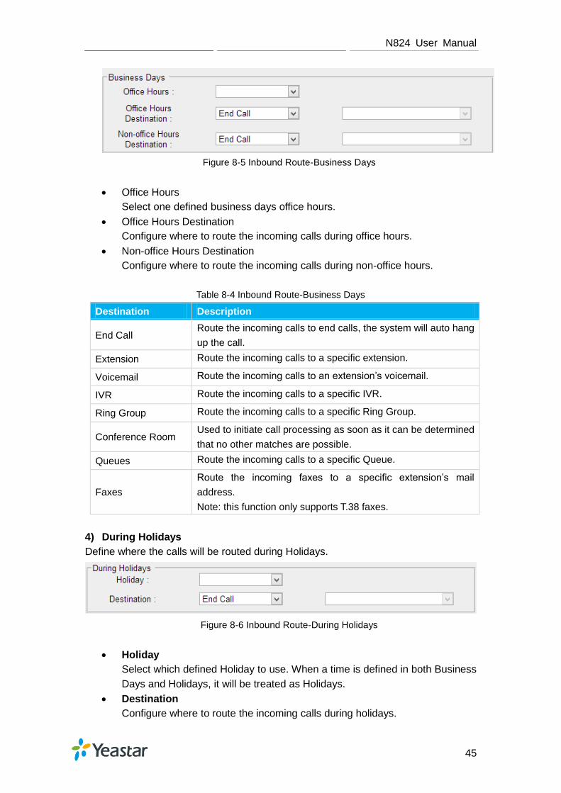
3) Business Days Define where the calls will be routed during Business Days.
N824 User Manual
45
Figure 8-5 Inbound Route-Business Days
Office Hours
Select one defined business days office hours.
Office Hours Destination
Configure where to route the incoming calls during office hours.
Non-office Hours Destination
Configure where to route the incoming calls during non-office hours.
Table 8-4 Inbound Route-Business Days
Destination Description
End Call Route the incoming calls to end calls, the system will auto hang
up the call.
Extension Route the incoming calls to a specific extension.
Voicemail Route the incoming calls to an extension’s voicemail.
IVR Route the incoming calls to a specific IVR.
Ring Group Route the incoming calls to a specific Ring Group.
Conference Room Used to initiate call processing as soon as it can be determined
that no other matches are possible.
Queues Route the incoming calls to a specific Queue.
Faxes
Route the incoming faxes to a specific extension’s mail
address.
Note: this function only supports T.38 faxes.
4) During Holidays Define where the calls will be routed during Holidays.
Figure 8-6 Inbound Route-During Holidays
Holiday
Select which defined Holiday to use. When a time is defined in both Business
Days and Holidays, it will be treated as Holidays.
Destination
Configure where to route the incoming calls during holidays.

N824 User Manual
46
5) Fax Detection
Enable or disable the "Fax Detection" functionality on this route.
Figure 8-7 Inbound Route-Fax Detection
No Detect
No attempts are made to auto-determine the call type. All calls are sent to the
defined destination.
Custom Email
Customize an E-mail address to receive the faxes. You should first configure the
―Voicemail Settings->SMTP Settings for Voicemail‖ correctly before you use this
option.
Faxes
Send faxes to an extension. If choosing a FXS extension here, the fax will be sent
to the FXS port selected, you should connect a fax machine to this FXS port. If
choosing a VoIP extension, the fax will be sent to the extension’s voicemail as an
attachment.
Note:
If you want to receive faxes with custom Email address, the SMTP Settings should be
configured successfully in advance. If you want to receive faxes with E-mail address
configured in VoIP extension voicemail, you should first make sure the tested email to
your email address works fine.
PIN Settings
Go to PBX→Advanced Settings→ PIN Settings to create a PIN list. The PIN lists
can be selected to access restricted features. The PIN can also be added to the CDR
record’s ―Account Code‖ field. PIN list can be applied to Outbound Route.
Figure 8-8 PIN Settings

N824 User Manual
47
Blacklist
Blacklist is used to block an incoming/outgoing call. If the number of
incoming/outgoing call is registered in the number blacklist, the caller will hear the
following prompt: ―The number you have dialed is not in service. Please check the
number and try again‖. The system will then disconnect the call.
Go to PBX→Advanced Settings→Blacklistto add numbers to the blacklist.
You can choose to block the number for inbound, outbound or both.
If the type is ―inbound‖, then this number can’t be called.
If the type is ―outbound‖, then the extensions in N824 can’t call this number.
Figure 8-9 Number Blacklist

N824 User Manual
48
IVR
Like most organizations, where possible, we would like to route incoming calls an
Auto Attendant. You can create one or more IVR (Auto Attendant) on N824 to achieve
it. When calls are routed to an IVR, N824 will play a recording prompting them what
options the callers can enter such as ―Welcome to XX, press 1 for Sales and press 2
for Technical Support‖.
Configure IVR
Go to PBX→Inbound Call Control→IVR to configure IVR.
Click to add a new IVR.
Click to delete the selected IVR.
Click to edit one IVR.
Click to delete one IVR.
Please check the IVR configuration parameters below.
Table 9-1 IVR Configuration Parameters-General Settings
General Settings
Number N824 treats IVR as an extension; you can dial this extension
number to reach the IVR from internal extensions.
Name Set a name for the IVR.
Prompt
Choose which recording to be played to the caller when they
reach the IVR. You can choose the default prompt on N824 or
choose a Custom Prompt which is uploaded or created on
N824.
Repeat Count The number of times that the selected IVR prompt will be
played.
Key Timeout
How long (in seconds) we wait for the caller to enter an option
on their phone keypad before we consider it timed out and it
follows the Timeout Destination as defined below.
Enable Direct Dial
Tick this option to enable Direct Dial. If Direct Dial is enabled,
the callers can enter a user's extension number when entering
the IVR to go direct to the users.

N824 User Manual
49
Key Press Events
Key Press Event
0
1
2
3
4
5
6
7
8
9
#
*
Timeout
Invalid
Select the destination for each key pressing: digits 0-9, ―#‖, ―*‖,
Timeout and Invalid. When the callers press the corresponding
key, the call will be routed to:
Extension
Voicemail
Ring Group
IVR
Conference Room
Queues
Faxes
Dial by Name
Hangup

N824 User Manual
50
Ring Group
A ring group helps you to ring a group of extensions in a variety of ring strategies. For
example, you could define all the technical support guys' extensions in a ring group
and ring the support guys one by one.
Configure Ring Group
Go to PBX→Inbound Call Control→ Ring Group to configure ring group.
Click to add a new Ring Group.
Click to delete the selected ring groups.
Click to edit one Ring Group.
Click to delete one Ring Group.
Please check the Ring Group configuration parameters below.
1) General Settings
Table 10-1 Ring Group Configuration Parameters-General Settings
General Settings
Ring Group Name Used to identify the ring group.
Ring Group Number This option defines the numbered extension that can be dialed
to reach this group.
Strategy
Select an appropriate ring strategy for this ring group.
Ring All Simultaneously: ring all the available extensions
simultaneously.
Ring Sequentially: ring each extension in the group one at
a time.
Seconds to ring
each member
Specify how long (in second) to ring each extension or all the
extensions.
If the strategy is ―Ring All Simultaneously‖, it means the
number of seconds to ring this group before routing the call
according to the ―Destination if No Answer‖ settings.
If the strategy is ―Ring Sequentially‖, it means the number
of seconds to ring a single extension before moving on to
the next one.

N824 User Manual
51
2) Ring Group Member
Specify the extensions to be part of this ring group. Move the desired ring group
members to the "Selected" Box.
Figure 10-1 Ring Group Member
3) Destination if No Answer
When all members on this group fail to answer the call, system will handle the call
according to the selected destination.
Figure 10-2 Destination if No Answer

N824 User Manual
52
Queue
Queues are designed to receiving calls in a call center. A queue is like a virtual waiting
room, in which callers wait in line to talk with the available agent. Once the caller
called in N824 and reached the queue, he/she will hear hold music and prompts, while
the queue sends out the call to the logged-in and available agents. A number of
configuration options on the queue help you to control how the incoming calls are
routed to the agents and what callers hear and do while waiting in the line.
Configure a Queue
Go to PBX→Inbound Call Control→ Queues to configure queues.
Click to add a new Queue.
Click to delete the selected queues.
Click to edit one queue.
Click to delete one queue.
Please check the Queue configuration parameters below.
1) General Settings
Table 11-1 Queue Configuration Parameters-General Settings
General Settings
Name A name for the Queue. The name is used for identification
purpose throughout the user interface.
Number Use this number to dial into the queue, or transfer callers to this
number to put them into the queue.
Queue Password You can require agents to enter a password before they can
login to this queue.
Queue Agent
Timeout
The number of seconds an agent's phone can ring before we
consider it a timeout.
Queue Max Wait
Time
The maximum number of seconds a caller can wait in a queue
before being pulled out. (0 for unlimited).
Queue Ring
Strategy
Multiple strategies are available for the queue.
RingAll:ring all available agents simultaneously until one
answers.
LeastRecent:ring the agent which was least recently
called.
FewestCalls:ring the agent with the fewest completed

N824 User Manual
53
calls.
Randoml:ring a random Agent.
RRmemory:Round Robin with Memory, remembers where
it left off in the last ring pass.
2) Agents
This selection shows all users. Selecting a user here makes them a dynamic
agent of the current queue. The dynamic agent is allowed to log in and log out the
queue at any time.
The agents dial "Queue number" + "*" to log in or "Queue number" + "**" to log out
the queue. For example, if the queue number is "681", then the dynamic agent
can dial "681*" to log in or "681**" to log out.
Figure 11-1 Agents
3) Caller Position Announcement
Figure 11-2 Caller Position Announcement
Table 11-2 Caller Position Announcement
Caller Position Announcement
Announce Position Whether to announce position of call in the queue or not.
Announce Hold
Time
Enabling this option causes N824 to announce the hold time to
the caller periodically based on the frequency timer. The hold
time will not be announced if the time is less than 1 minute no
matter this option is set to yes or no.
Frequency How often to announce the queue position and estimated hold
time.
4) Periodic Announcements
The periodic announcement is played periodically when the caller is waiting on the

N824 User Manual
54
line.
Figure 11-3 Periodic Announcements
5) Events
Once the events settings are configured, the callers are able to press the key to
enter the destination you set. Usually, a prompt should be set on Periodic
Announcementsto guide the callers to press the key.
Figure 11-4 Events
6) Failover Destination
Define the failover action. A failover occurs after the user reach the Queue max
wait time.
Figure 11-5 Failover Destination
7) Others
Figure 11-6 Queue Others Settings
Table 11-5 Queue Others Settings
Others
Music on Hold Select the "Music on Hold" Prompt for this queue.
Leave When Empty
This option controls whether callers already on hold are forced
out of the queue that has no agents.
Yes: callers are forced out of a queue when no agents are

N824 User Manual
55
logged in.
No: callers will remain in the queue without any agent.
Join Empty
This option controls whether callers can join a call queue that
has no agents.
Yes: callers can join a call queue with no agents or only
unavailable agents
No: callers cannot join a queue with no agents
The default setting is "No".
Ring in Use If set to "No", the queue will avoid sending calls to members
whose devices are known to be "in use".
Agent
Announcement
Announcement played to the agent prior to bringing in the
caller.
Join Announcement Announcement played to callers once prior to joining the queue.
Retry The amount of seconds the queue waits after calling all
available agents before calling them again.
Wrap-up Time
The amount of seconds the queue waits for passing another
queue call to an agent who has completed a call (0 for no
delay).

N824 User Manual
56
Conference
Conference Calls increase employee efficiency and productivity, and provide a more
cost-effective way to hold meetings. Conference agents can dial * to access to the
settings options and the admin can kick the last user out and can lock the conference
room.
Configure a Conference Room
Join a Conference Room
Manage the Conference
Configure a Conference Room
Go to PBX→Inbound Call Control→ Conferences to configure conferences.
Click to add a new Conference Room.
Click to delete the selected conference
rooms.
Click to edit one Conference Room.
Click to delete one Conference Room.
Please check the Conference configuration parameters below.
Table 12-1 Conference Configuration Parameters
Options Description
Extension Use this number to dial into the conference room.
Admin Admin can kick a user out and can lock the conference room.
PIN# You can require callers to enter a password before they can
enter this conference. This setting is optional.
Join a Conference Room
Users on N824 could dial the conference extension to join the conference room. If a
password is set for the conference, users would be prompted to enter a PIN.
How to join a N824 conference room, if I am calling from outside (i.e. calling from
my mobile phone)?
In this case, an inbound route for conferences should be set on N824. A trunk should

N824 User Manual
57
be selected in the inbound route and destination should be set to a conference room.
When the outside users dial in the trunk number, the call will be routed to the
conference room.
Manage the Conference
During the conference call, the users could manage the conference by pressing * key
on their phones to access IVR menu for conference room.
Please check the options for conference IVR below.
Table 12-2 Conference IVR Menu
Conference Administrator IVR Menu
1 Mute/ un-mute yourself.
2 Lock /unlock the conference.
3 Eject the last user.
4 Decrease the conference volume.
5 Extend the conference.
6 Increase the conference volume.
7 Decrease your volume.
8 Exit the IVR menu.
9 Increase your volume.
Conference Users IVR Menu
1 Mute/ un-mute yourself.
4 Decrease the conference volume.
6 Increase the conference volume.
7 Decrease your volume.
8 Exit the IVR menu.
9 Increase your volume.

N824 User Manual
58
Managing Voice on N824
In this chapter, we introduce how to manage voice on N824, including the following
sections:
System Prompt
Custom Prompt
Music on Hold
System Prompt
N824 ships with a US English prompt set by default. The system supports multiple
languages. Users could update the system prompt in different ways. Go to
PBX→Audio Settings→System PromptsSettings to update the system prompt.
HTTP/Auto Mode (Recommended)
Please make sure your N824 can access the internet before you update system
prompt with this method.
Users could choose the desired prompts and click download to update directly without
reboot.
Figure 13-1 Update System Prompts- Auto Detection
Another way is choose Download Mode as "HTTP" and fill in the URL to download
system prompt and update it.
Figure 13-2 Update System Prompts- HTTP Download

N824 User Manual
59
Download link of system prompt is as below:
America
Arabic
Australia
British
Chinese
Danish
Deutschland
Dutch
Finnish
French
French Canada
Greek
Hungarian
Italian
Korean
Norwegian
Persian
Polish
Portuguese
Portuguese Brazil
Russian
Spanish
Spanish Latin
Spanish Mexico
Swedish
Thai
Turkish
TFTP Method
If N824 cannot access the internet, please update the system prompts via TFTP.
Step1.Download the system prompt to your local PC.
Step2.Enable TFTP Server (For example, tftpd on Windows)

N824 User Manual
60
1) Install tftpd32 software on computer.
Download link:http://tftpd32.jounin.net/tftpd32_download.html
2) Configure tftpd32
For the option ―Current Directory‖, click ―Browse‖ button, choose the system
prompt file of N824, such as D:\fr.tar.gz.
Figure 13-3 Configure Tftpd32
Step3.Update via TFTP
1) TFTP Server: fill in IP address of tftpd32 server, such as 192.168.6.42.
2) File Name: Enter the name of voice prompt tar file name, such as "fr.tar.gz".
3) 3) Click to download the system prompt and update.
Figure 13-4 Update System Prompts- TFTP Download

N824 User Manual
61
Custom Prompt
The default voice prompts and announcements in N824 are suitable for almost every
situation. However, you may want to use your own voice prompt to make it more
meaningful and suitable for your case. In this case, you need to upload a custom
prompt to N824 and apply it to the place you want to change.
Custom Prompt can be found via the path PBX→ Audio Settings → Custom
Prompts. On the Custom Prompt page, you can record a new prompt or upload your
audio file to N412.
Record New Prompt
The administrator can record custom prompts by doing the following:
1) Click the button .
2) Input the desired file name on the popup window and choose an extension to call
for recording (such as 601).
3) Click . The selected extension will ring and you can pick up the
phone to start recording.
Figure 13-5 Record New Prompt
Upload Custom Prompt
1) Click the button .
2) Click to choose the desired prompt.
Figure 13-6 Upload Custom Prompt

N824 User Manual
62
3) Click to upload the selected prompt.
Note:
The file size must not be larger than 8 MB, and the file must be WAV format:
GSM 6.10 8 kHz, Mono, 1 Kb/s
Alaw/Ulaw 8 kHz, Mono, 1 Kb/s
PCM 8 kHz, Mono, 16 Kb/s
Music on Hold
Music on hold (MOH) is the business practice of playing recorded music to fill the
silence that would be heard by callers who have been placed on hold. There are 3
default MOH files built in N824, you can also upload the one you want to N824.
Upload a Music on Hold Prompt
Upload a custom prompt viaPBX→Audio Settings→Music on Hold Prompts.
1) Click the button .
2) Click to choose the desired prompt.
Figure 13-7 Upload Music on Hold File
3) Click to upload the selected prompt.
Note:
The file size must not be larger than 8 MB, and the file must be WAV format:
GSM 6.10 8 kHz, Mono, 1 Kb/s
Alaw/Ulaw 8 kHz, Mono, 1 Kb/s
PCM 8 kHz, Mono, 16 Kb/s
Play a Music on Hold Prompt
Choose a Music on Hold file via PBX→Audio Settings→Music on Hold Prompts
and click to play the prompt. Choose one extension to play the prompt. Once

N824 User Manual
63
clicked the button , the selected extension will ring. Pick up the phone and
listen to the music.
Figure 13-8 Play a Music on Hold Prompt

N824 User Manual
64
Voicemail
In this chapter, we introduce how to manage voicemail system on N824, including the
following sections:
Voicemail Settings
Voicemail to Email
How to Check Voicemail?
How to Change Voicemail Greetings?
Voicemail Settings
Users could configure voicemail settings, including general voicemail settings and
SMTP settings (which is used for ―Voicemail to Email‖) via PBX→Basic
Settings→Voicemail Settings.
1) General Settings
Table 14-1 Voicemail- General Settings
General Voicemail Settings
Max Message per Folder Set the maximum number of messages that can be
stored in a single voicemail box.
Max Message Time Set the maximum length of a single voicemail
message.
Min Message Time
Set the minimum length of a single voicemail
message. Messages below this threshold will be
automatically deleted.
Ask Caller to Dial 5 If this option is set, the caller will be prompted to press
5 before leaving a message.
Delete Voicemail After notification, the voicemail is deleted from the
server.
Operator Breakout from
Voicemail
If this option is set, the caller can jump out of the
voicemail and go to the destination you set by dialing
―0‖.
Destination The caller will go to the destination by dialing ―0‖.
2) SMTP Settings
Please ensure the SMTP settings are configured correctly to make Voicemail to
Emailwork properly.
After finishing the configuration, you can click on the button
to check whether the setup is OK.

N824 User Manual
65
If the test is successful, you can use the email safely.
If the test failed, please check if the above information is input correctly or if
the network is OK.
Figure 14-1 Voicemail-SMTP Settings
E-mail Address
The E-mail Address that N824 will use to send voicemail.
Password
The password for the email address used above.
SMTP Server
The IP address or hostname of an SMTP server that the N824 will connect in
order to send voicemail messages via email.
Port
SMTP Port: the default value is 25.
Use SSL/TLS to send secure message to server
If the email sending server needs to authenticate the sender, you need to
select the check box.
Note:
SSL/TLS must be selected if you use Gmail or Exchange Server.
Voicemail to Email
Voicemail is enabled for each extension on N824 by default. If there is no answer for
an extension, the call will be forwarded to the extension's voicemail. Email notification
of voicemails are supported on N824, simply enable this feature on the desired
extension edit page. Enter your email address in the Email Address field, the received
voicemails will be sent to your email.

N824 User Manual
66
Figure 14-2 Enable Voicemail to Email
Note:
Please ensure that the section of "SMTP Settings for Voicemail" (in the "Voicemail
Settings") has been properly configured before using this feature.
How to Check Voicemail?
There are multiple ways to check voicemail on N824. You can check the voicemail by
pressing voicemail feature code on your phone or log in N824 by Extension account to
check voicemails. In addition, you can check voicemail via Email if Voicemail to Email
is enabled.
1) Check Voicemail by Phones
The default feature code to check a specific extension's voicemail is *2.
Dial *2 on your phone, and enter the voicemail PIN code to access your voicemail.
The default voicemail PIN number is the same as your extension number. The
password can be changed on the extension edit page.
You can also check other extension's voicemail on your own handset by using
feature code *02. Dial *02 on your phone to enter the voicemail main menu.
Entering the desired extension number and followed by the extension's voicemail
PIN, you will be able to check the extension's voicemail.
2) Check Voicemail on Web
Another way to check voicemail is logging in N824 by Extension User Account.
Before logging in N824 Web using the extension User account, you should
enable ―User Web Interface‖ for the extension.

N824 User Manual
67
Figure 14-3 Enable User Interface
User Name: Extension Number
Password: Web Password for the extension
Figure 14-4 Login N824 via Extension Account
After login, you can check voicemail on "Voicemail" page.
3) Check Voicemail via Email
If you have enabled "Voicemail to Email" feature, you can check voicemail on
your email.
How to Change Voicemail Greetings?
The default Voicemail greeting on N82 is fine but it is rather bland and quite boring.

N824 User Manual
68
You can customize your own voicemail greetings.
1. Dial *2 to enter voicemail on your handset.
2. Enter the access password.
3. Press 0 for Mailbox Options. You will then be given the choice what type of
message you want to record.
4. Press 1 to record your Unavailable Message.
5. Press 2 to record your Busy Message.
6. Press 3 to record your name.
7. Press 4 to record your Temporary Message.
8. Choose the message that you want to record, press # to finish the record.
9. Press 1 to accept your message.
10. Press 2 to listen to your message.
11. Press 3 to re-record your message if you don't like the previous message.

N824 User Manual
69
Business Calling Features
This chapter shows various call features on N824:
Feature Code
Call Transfer
Call Pickup
Intercom
Spy
Call Parking
Speed Dialing
Feature Code
Feature Codes are used to enable and disable certain features available in N824.
N824 local users can dial feature codes on their phones to use a particular feature.
The default feature codes can be checked and changed on PBX→Basic
Settings→Feature Codes page.
1) General
Table15-1 Feature Code-General
General
One Touch Record
Default Code: *1.
A user may initiate or stop call recording by dialing the code
during a call.
Check Extension
Voicemail
Default Code: *2.
Users could check their own voicemails by this code.
Voicemail for Extension
Default Code: #.
Users can leave a voicemail to other extensions by dialing #
on their phone or the incoming call could be forwarded to an
extension’s voicemail directly. (# is the default setting). For
example, extension 500 want to leave a message for
extension 501, users can use 500 dial ―#501‖ to enter the
voicemail of 501.
Voicemail Main Menu Default Code: *02.
Attended Transfer
Default Code: *3.
Attended Transfer Timeout:
The timeout value of transferring a call.
Blind Transfer Default Code: *03.
Call Pickup Default Code: *4.

N824 User Manual
70
Extension Pickup
Default Code: *04.
Users may pick up a specific extension’s incoming call by
dialing *04+extension number on their phone.
Intercom Default Code: *5.
Normal Spy Default Code: *90.
In this mode, you can only listen to the extension being spied.
Whisper Spy
Default Code: *91.
In this mode you can listen/whisper to the extension being
spied.
Barge Spy
Default Code: *92.
In this mode, you can barge in both extensions involved in the
call.
Input Digit Timeout Default: 4000ms.
The timeout to input the next digit.
2) Call Parking Preferences
Table 15-2 Call Parking Preferences
Call Parking Preferences
Call Parking Default Code: *6.
Extension range used to park calls
Default: 690-699.
User may park an incoming call on a
designated extension at first and then pick
up the call again on any other extensions.
Number of seconds a call can be parked for
Default: 60s.
Define the time (in seconds) that a call
can be parked before it is recalled to the
station that parked it.
3) Call Forwarding Preferences
Table 15-3Call Forwarding Preferences
Call Forwarding Preferences
Reset to Defaults
Default Code: *70.
The call forwarding settings will be configured as
follows:
Always forward: Disabled
Busy forward to Voicemail: Enabled
No answer forward to Voicemail: Enabled
Do not disturb: Disabled
Enable Forward All Calls Default Code: *71.
Disable Forward All Calls Default Code: *071.
Enable Forward When Busy Default Code: *72.
Disable Forward When Busy Default Code: *072.

N824 User Manual
71
Enable Forward No Answer Default Code: *73.
Disable Forward No Answer Default Code: *073.
Forward to Number Default Code: *74.
Forward to Voicemail Default Code: *074.
Enable Do Not Disturb Default Code: *75.
Disable Do Not Disturb Default Code: *075.
Call Transfer
There are 2 types of call transfers available on N824: Blind Transfer and Attended
Transfer. Users can achieve call transfer by pressing the feature code during the call.
Blind Transfer
Default feature code: *03
1. Dial "*03" during the call;
2. Dial the called number after hearing a prompt "transfer";
3. The call will be transferred after the number is dialed.
Attended Transfer
Default feature code: *3
1. Dial "*3" during the call;
2. Dial the called number after hearing a prompt "transfer";
3. Talk to the transfer recipient;
4. The call will be transferred after hanging up.
On PBX→Basic Settings→General Preferences page, you can set the Attended
Transfer Caller ID. The default display is the Caller ID of the initiator.
For example, if extension 500 makes a call to extension 501. After 501 picks up the
call, user501 makes an attended transfer to extension 502.
If selecting ―Transferer‖, 502 will display the Caller ID as 501;
If selecting ―Transferee‖, 502 will display the Caller ID as 500.
Call Pickup
Call Pickup is a feature that allows one to answer someone else's call. The feature is
accessed by pressing call pickup feature code on N824. If a colleague's phone set is
ringing, one can answer that call by picking up one's own set and then using the call

N824 User Manual
72
pick-up feature, instead of walking to the colleague’s desk.
Group Call Pickup
The default call pickup for Group Call Pickup is *4. It allows you to pick up a call
from a ringing phone which is in the same group as you.
Pickup group can be set on extension edit page. Extensions that are in the same
group can pick up each other's call by feature code *4.
Figure 15-1 Group Extensions
Direct Call Pick
The default Direct Call Pickup (Extension Pick up) feature code is *04. It allows you to
pick up a call that is made to a specific extension. If you know whose phone is ringing
and what is the extension number is, you can pick up the call by pressing *04+
extension number.
N824 User Manual
73
For example, if a call reaches the Sales Department Manager's phone (extension
number 888), but he is in a meeting, you can pickup the call by pressing *04888 on
your own phone to answer the call.
Intercom
Intercom is a feature that allows you to make an announcement to one extension via
a phone speaker. The called party does not need to pick up the handset. It can be
achieved by pressing the feature code on your phone and it is a two-way audio call.
The default Intercom feature code is *5. To make an announcement to a specific
extension, you need to dial *5+ extension number on your phone. For example, make
an announcement to extension 500, you need to dial *5500, then the extension 500
will be automatically picked up.
Spy
N824 allows extension to monitor/barge in other conversation. Once this feature is
enabled, the extension has the ability to monitor/barge in other calls using the feature
codes for each spy mode.
Spy Modes
General spy: you have the permission to use the following 3 modes.
Normal spy: you can only hear the call, but can't talk. Feature code: *90.
Whisper spy: you can hear the call, and can talk with the monitored extension.
Feature code: *91.
Barge spy: you can hear the call and talk with them both. Feature code: *92.
Steps to Use Spy Feature
Example: UseExtension100to monitor the calls of Extension 101.
1. Enable "Allow Being Spied" in extension 101. In this case, extension 101 is
allowed to be spied by other extensions.
2. Choose the "Spy Modes" for extension 100. In this case, extension 100 has the
right to use the feature code to monitor extension 101.
3. If 100 choose ―normal spy‖, it should dial ―*90301‖ to start monitoring;
If 100 choose ―whisper spy‖, it should dial ―*91301‖ to start monitoring;
If 100 choose ―barge spy‖, it should dial ―*92301‖ to start monitor;
If 100 choose ―general spy‖’, it can dial ―*90301‖, ―*91301‖ or ―*92301‖ to start
monitor.

N824 User Manual
74
Call Parking
Call Parking is a feature that allows the user to put a call on hold at one phone and
continue the conversation from any other phone. Call parking is activated by feature
code. For example, extension 8010 is in a call, but the person needs to go to another
place to find the answer for a question. He can dial Call Parking feature code on the
phone, and system will prompt that the call is parked at an extension, i.e. 690.Then
this person can hang up the call and leave. When he finds the information, he can pick
up any phone nearby and dial 690 to resume the conversation.
Uses of Call Parking
Call parking is often useful in buildings with many offices or with more than one floor,
and with most of the areas having access to one or more telephone sets.
If the desired called party is not the person who picked up the call, and the
desired called party is at an unknown location, the person who picked up the call
may park the call and then use the public address system to page the desired
called party to pick up the call.
During a conversation, a person may need to go to another office for some
reason (for example, to retrieve an important file); parking the call allows this
person to continue the conversation after arriving at the other office.
Speed Dialing
Sometimes you may just need to call someone quickly without having to look up
his/her phone number. You can by simply define a shortcut number. Speed Dial
feature is available on N824 that allowing you to place a call by pressing a
reduced number of keys.
Add a Speed Dial
1. Go toPBX→Outbound Call Control→Speed DialSettings, you can see the
default Speed Dial Prefix is *99. Please avoid conflict with other feature codes if
you want to change the prefix.
2. Click to add one Speed Dial.
3. Fill in the Source Number and Destination Number.
Number for the number you want to call.
Speed Dial Code for speed dialing number.

N824 User Manual
75
Note:
Do not forget to add the outbound dial prefix if you would like to dial the speed dial
number through trunk.
Figure 15-2 Speed Dial
To make a speed dial, e.g. you want to call 15880246258, simply dial *991. The *99
tells N824 that you want to use the Speed Dial and the 1 is the Speed Dial Code for
destination number 15880246258. (Check the Speed Dial Setting for 15880246258
on the screen above.)

N824 User Manual
76
Auto Recording
This chapter explains how to configure auto recording on N824 and how to manage
the recording files.
Auto Recording Settings
SD Card Management
Store Recordings to Network Disk
Share Recordings
Auto Recording Settings
N824 supports auto recording for an established call. Go to System→ Auto
Recording Settings→ Recording Settings to configure auto recording settings.
Note: before enabling call recording, please make sure that the SD card or the Net
Disk performs well.
Table 16-1 Auto Recording Configurations
General Preferences
Enable Call Recording
Enable or Disable Auto Recording feature.
You can choose:
Record Inbound calls
Record Outbound calls
Record Internal calls
Storage Location
After enabling Call recording, you can choose where to
store the recordings, in the Network Disk or in the SD
card.
Status: shows if the SD card or Network Disk is
successfully mounted to N824.
Record Inbound Prompt
If Call Recording is enabled, the caller will hear the
preconfigured prompt when the inbound calls go through
trunks.
Written to the Recording file:
If enabled, the prompt will be recorded.
Record Outbound Prompt
If Call Recording is enabled, the callee will hear the
preconfigured prompt when the outbound calls go through
trunks.
Written to the Recording file:
If enabled, the prompt will be recorded.
Apply To
Record Trunks When ticked, all calls through the selected trunks will be

N824 User Manual
77
recorded.
Record Extensions When ticked, all calls made by the selected extensions
will be recorded.
Record Conferences When ticked, all conversations through the selected
conferences will be recorded.
SD Card Management
Insert a SD Card to N824, then manage and check the SD check status under
System→ Storage Management→ SD Card Management.
You can format or clean up the SD card on this page.
Note:
You should power off your machine when you put in or pull out your SD card.
If you want to clear up the SD card, please check if you need to back up the files
in it.
Figure 16-1 SD Card Management
Store Recordings to Network Disk
The Network Disk feature is used to extend storage space. If ―Storage Location‖ is set
to Network Disk, the call recording files created will be moved to the NetDisk.
Configure the Network Disk under System→ Storage Management→ Network Disk
Settings.
Note:
The shared folder must be based on Windows Operation System. And if it's windows
Vista/2008/7, please add ―Everyone‖ into the shared account list. After that you should
ensure that the permission of ―Everyone‖ is checked.

N824 User Manual
78
Figure 16-2 Add Everyone
Figure 16-3 Share the File
Before network disk can be properly configured, an SMB share folder accessible from
N824 must be set up on a Windows based machine. Once that has been set up,
please follow the steps below.
1. Choose a window-based computer that is always in service
2. Create a folder
3. Share this folder

N824 User Manual
79
4. Input the Net-Disk information in ―Connect to Network Disk‖ tab.
Figure 16-4 Connect to Network Disk
Table 16-2 Network Disk Settings
Network Disk Settings
Running Status Shows if the Net-Disk is successfully mounted to N824.
Enable Yes: Enable Network Disk
No: Disable Network Disk
Net-Disk Host/IP Set the IP address where the recordings will be stored.
Net-Disk Share Name The shared folder name where the recordings will be
stored.
Net-Disk Access User Name
The User name used to log in the Network share. Leave
this blank if it is not required. In general, you use the
administrator account on PC as a user name here.
Net-Disk Access Password The password used to log into the network share.
Leave this blank if it is not required.
If the configuration is correct, you will see the Network Disk information.
Figure 16-5 Network Disk Status
Share Recordings
Users could share recordings on the network. This setting is only applied to the Call
Recording folder in the SD Card. Go to System→ Storage Management→ Network
Disk Settings to configure the sharing settings.

N824 User Manual
80
Figure 16-6 Share Recordings
Table 16-3 Sharing Settings
Sharing Settings
Share Name The name of the folder showed on the network.
User Name The user name to access the files.
Password The password for the user name.
Check Shared Recordings
Open a file folder on your PC, and type N824 IP address (\\IP Address ) to check the
shared recordings.
Example: \\192.168.5.149
Figure 16-6 Check Shared Recordings
How to check the Network User?
1. Start-> Run ->cmd
2. Execute the command net use * /del(there is a space behind *)
3. Visit the device again with the new password

N824 User Manual
81
For WIN 7/Win8 Users
Please modify the registry before checking the shared file.
1. Start->Run->regedit
2. Modify the value of
HKEY_LOCAL_MACHINE\SYSTEM\CurrentControlSet\Control\Lsa\
LmCompatibilityLevelto 1
If LmCompatibilityLevel doesn’t exit, create a Dword value LmCompatibilityLevel= 1.

N824 User Manual
82
PBX Basic Settings
This chapter explains PBX basic settings, which can be applied globally to N824. The
basic settings can be configured under PBX→Basic Settings.
General Preferences
Business Hours
General Preferences
1) General Settings
Table 17-1 General Preferences-General
General Settings
Max Duration The absolute maximum amount of time permitted for a call. A
setting of 0 disables the timeout. The default value is 6000s.
Music On Hold Used to set hold music for the system.
Tone Region
Select country to set the default tones (dial tone, busy tone, ring
tone and etc.) to be sent from FXS port.
The default setting is United States/North America.
Dsp Fax Enable Dsp to optimize Fax reception.
FXO Mode
Select country to set the On Hook Speed, Ringer Impedance,
Ringer Threshold, Current Limiting, TIP/RING voltage
adjustment, Minimum Operational Loop Current, and AC
Impedance as predefined for your country's analog line
characteristics.
The default setting is FCC for USA.
Attended Transfer
Caller ID
When transferring an incoming call using the attended transfer
feature code or the transfer key of IP phone, the Caller ID of
transferee or transferer displayed on the screen of the callee.
The default display is the Caller ID of the initiator.
Follow Me Prompt
If ―Enable Follow Me Prompt‖ choosing yes, there will be
prompt before transferring the call. Otherwise, the call will be
transferred directly without any prompt. Default: Yes.
Music on hold for
Follow Me
Configure whether to play a prompt ―please hold while I try to
locate the person you are calling‖ when transfer a call by follow
me settings.
Invalid Phone Number
Prompt Configure the prompt when the dialed phone number is invalid.
Busy Line Prompt Configure the prompt when the dialed phone number is busy.
Dial Failure Prompt Configure the prompt when dial failed due to conjunction

N824 User Manual
83
no-available channel.
Enable Last Caller
Routing
Whether to enable the feature Last Caller Routing.
When an extension is making an outbound call, the system will
automatically record the information, and when the dialed
number make an inbound call using the same line, this number
will directly reach the corresponding internal extension.
Keep Time How long you want to keep the Last Caller Routing records.
Internal Ring Type Select the Ring tone type for internal calls.
Inbound Ring Type Select the ring tone type for inbound calls.
2) Web Server
N824 supports web server responds to HTTP and HTTPS. By default, users could
access the Web GUI via HTTP (default port: 80). You can also access web via HTTPS
if HTTPS is enabled.
Figure 17-1 Web Sever
3) Extension Preferences
You can change extension preferences on this Section. There are 5 types of
extension range, including User Extensions, Ring Group Extensions, Conference
Extensions, IVR Extensions, and Queue Extensions. Assign a specific range for each
type will help to distinguish and manage those different extensions.
You could change the default range or redefine it to meet your requirements. The
extension number should have at least 2 digits and at most 7 digits.
Figure 17-2 Extension Preferences
Business Hours
On Business Hours page, you can create a list of times (Office Hours, Other Office

N824 User Manual
84
Hours and Holiday) in which incoming or outgoing calls are checked. The rules
specify a time range, by the hour and/or date. Business Hours typically are associated
with time conditions, which match destinations for calls based on the time. Outbound
routes can also be assigned an Office Hours, making that route only available during
times defined in an Office Hours.
Go to PBX→Basic Settings→Business Hours to find Business Hours settings.
Figure 17-3 Business Hours
Enable Business Hours
Enable Office Closed Timing
By dialing *81 (*81 is the default code) on an extension will force the office time
closed for the device whatever the general setting is.
Enable Office Timing
By dialing *82 (*82 is the default code) on an extension will force the office time to
take effect for the device whatever the general setting is.
Disable Office closed timing
By dialing *081 (*081 is the default code) on an extension will disable the Office
Closed Timing.
Business Days
Generally, we add office hours according to your working time and set different
destinations for Office Hours and Non-office Hours.
Define the Office Hours or Other Office Hours name and set the time as the following
picture shows.

N824 User Manual
85
Figure 17-4 Business Days
Holidays
You can set up the holidays here.
If a time period is configured as both Holidays and office hours, it will be treated as
Holidays.

N824 User Manual
86
Figure 17-5 Holidays

N824 User Manual
87
SIP Settings
SIP settings can be configured on PBX→Advanced Settings→SIP Settings page.
It is wise to leave the default setting as provided on this page. However, for a few
fields, you need to change them to suit your situation.
General
NAT
Codecs
General
Table 18-1 SIP Settings-General
General Settings
UDP Port Port used for SIP registrations. The default is 5060.
RTP Port Start/End Set the RTP Port range.
DTMF Mode Set default mode for sending DTMF. Default setting: rfc4733.
Min Registration/
Subscription Time
Minimum duration (in seconds) of a SIP registration. The default is
60 seconds.
NAT
Configuration of this section is only required when you use remote extensions.
Table 18-2 SIP Settings- NAT
NAT Settings
Enable STUN Whether to enable STUN.
STUN Address STUN IP address.
STUN Port STUN port.
External IP Address The IP address that will be associated with outbound SIP
messages if the system is in a NAT environment.
External Host
Alternatively you can specify an external host, and the system
will perform DNS queries periodically.
This setting is only required when your public IP address is not
static. It is recommended that a static public IP address be used
with this system. Please contact your ISP for more information.
External Refresh
Interval
If an external host has been supplied, you may specify how often
the system will perform a DNS query on this host. This value is
specified in seconds.

N824 User Manual
88
Local Network
Identification
Used to identify the local network using a network number/subnet
mask pair when the system is behind a NAT or firewall.
Some examples of this are as follows:
―192.168.0.0/255.255.0.0‖: all RFC 1918 addresses are local
networks;
―10.0.0.0/255.0.0.0‖: also RFC1918;
―172.16.0.0/12‖: another RFC1918 with CIDR notation;
―169.254.0.0/255.255.0.0‖: zero conf local network.
Please refer to RFC1918 for more information.
NAT Mode
Global NAT configuration for the system; the options for this
setting are as follows:
Yes = Use NAT. Ignore address information in the SIP/SDP
headers and reply to the sender's IP address/port.
No = Use NAT mode only according to RFC3581.
Never = Never attempt NAT mode or RFC3581 support.
Route = Use NAT but do not include rport in headers.
Allow RTP Re-invite
By default, the system will route media steams from SIP
endpoints through itself. Enabling this option causes the system
to attempt to negotiate the endpoints to route packets to each
other directly, bypassing the system. It is not always possible for
the system to negotiate endpoint-to-endpoint media routing.
Codecs
A codec is a compression or decompression algorithm that used in the transmission of
voice packets over a network or the Internet. N824 supports G711 a-law, u-law, GSM,
SPEEX, iLBC, G722, G726, G729A,G729B and G729AB,
Note:
If you would like to use G.729, please enter your license. Our device have embedded
the G729, you can test it directly without purchasing license. But for copyright
protection, we suggest you to buy it after testing it successfully. After you buy the
license from DIGIUM, you should enter G729 license at the "G729 License Key".
Figure 18-1 SIP Settings-Codecs

N824 User Manual
89
Status and Call Reports
Users could check the system status on Status→System Status, where Extension
Status, Trunk Status, Network Status and System Info can be checked. CDR and Call
Recordings can be checked under Status→ Reports.
Extension Status
Trunk Status
Network Status
System Info
Call Logs
Record Logs
Extension Status
Users could view all the extension status on this page.
Figure 19-1 Extension Status
Table 19-1 Extension Status
Up/Down
Status for FXS Extensions:
Up: the FXS module works well.
Down: the FXS module is broken.
Registered IP
Status for SIP Extensions:
Unregistered: The SIP extension is not registered.
[IP]:[Port]: The SIP is successfully registered with the IP.
Example: 192.168.6.142:50113
Description: The extension is registered on IP 192.168.6.142.
Name Display the extension name.
Extension Display the extension number.
Status
Monitor the extension’s call status in real time.
Extension is unavailable

N824 User Manual
90
Extension is idle
Extension is ringing
Extension is busy
Extension is on hold
Voicemail
Display message status of the extension.
Format: New/Old
Example: 1/3
Description: There are 1 new voice message, and 3 old messages.
Trunk Status
Users could check all the PSTN trunks status and VoIP trunk status if VoIP trunk is
created.
Figure 19-2 Trunk Status
Table 19-2 VoIP Trunk Status
Domain Name/IP
Display the domain name/IP for the VoIP trunk.
[IP]:[Port]: display the IP address of the VoIP service
provider and the SIP registry port.
Example: 110.92.83.4:5060
Description: the extension is registered on IP
192.168.6.142 and the SIP port is 5060.
Provider Name Display the trunk name.
(VoIP) Status
VoIP trunk status:
Registered: successful registration, trunk is ready for
use.
Unreachable: cannot reach the VoIP service provider.
Failed: trunk registry failed.
Table 19-3 PSTN Trunk Status
Up/Down Status for CO lines:
Up: the CO line works well.

N824 User Manual
91
Down: the CO line is broken.
Trunk Name Display the trunk name.
(FXO) Status
PSTN trunk status:
Idle: the port is idle.
Busy: the port is in use.
Disconnected: there is no line connected to the port.
Network Status
Users could check the network status under Status→SystemStatus→Network
Status.
Figure 19-3 Network Status
System Info
The system info: product type, hardware version, firmware version, disk usage and
memory usage can be viewed under Status→System Status→System Info.
Figure 19-4 System Info
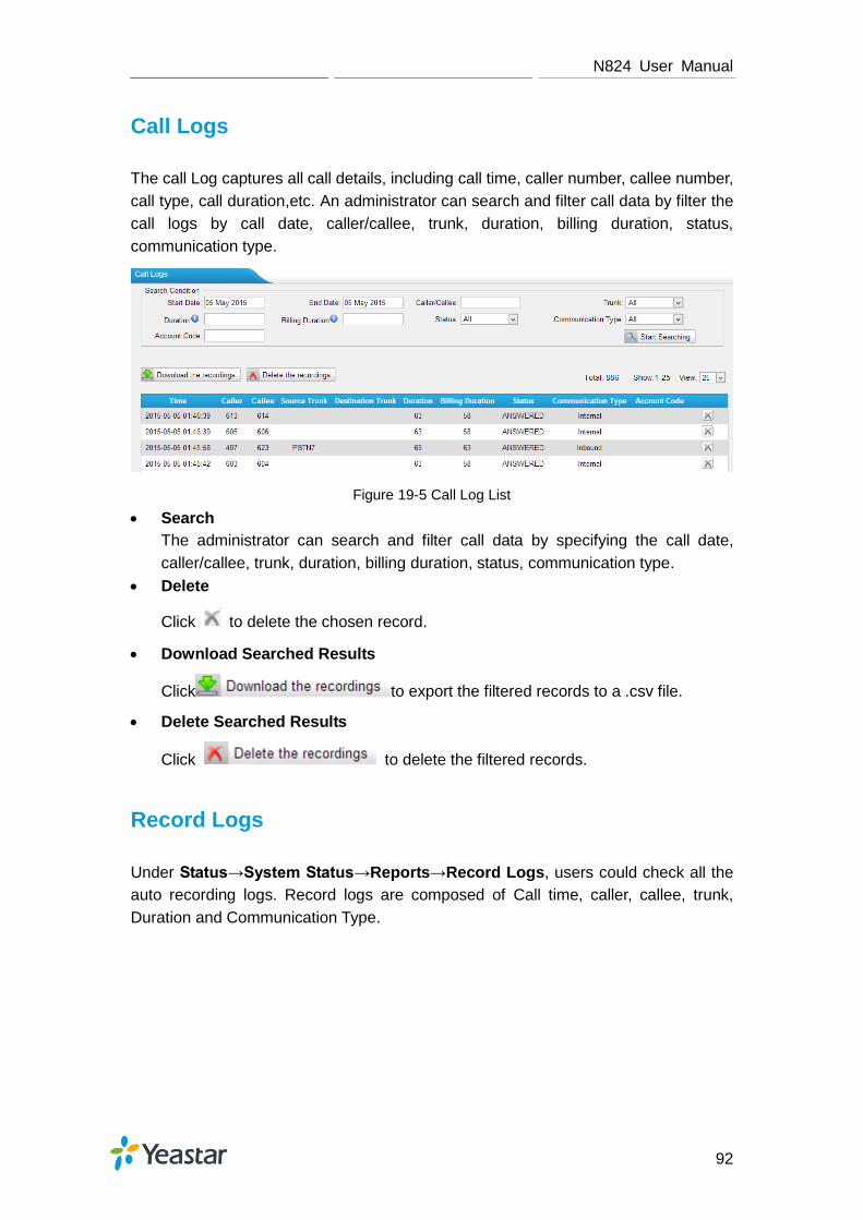
N824 User Manual
92
Call Logs
The call Log captures all call details, including call time, caller number, callee number,
call type, call duration,etc. An administrator can search and filter call data by filter the
call logs by call date, caller/callee, trunk, duration, billing duration, status,
communication type.
Figure 19-5 Call Log List
Search
The administrator can search and filter call data by specifying the call date,
caller/callee, trunk, duration, billing duration, status, communication type.
Delete
Click to delete the chosen record.
Download Searched Results
Click to export the filtered records to a .csv file.
Delete Searched Results
Click to delete the filtered records.
Record Logs
Under Status→System Status→Reports→Record Logs, users could check all the
auto recording logs. Record logs are composed of Call time, caller, callee, trunk,
Duration and Communication Type.

N824 User Manual
93
Figure 19-6 Record Logs
Search
The administrator can search and filter record data by specifying the call date,
caller/callee, trunk, duration, and communication type.
Play
Click to play the recording file.
Download
Click to download the chosen recording file.
Delete
Click to delete the chosen record.
Download the Selected Recordings
Click to download the selected recording
files.
Delete the Selected Recordings
Click to delete the selected recording files.

N824 User Manual
94
System Maintenance
This chapter describes system maintenance settings including the followings:
Firmware Upgrade
Backup and Restore
Reset and Reboot
System Logs
Packet Tool
Firmware Upgrade
N824 provides automatic updates, new firmware file will be checked via a cloud server.
In addition, firmware upgrade can be done via HTTP and TFTP manually on N824.
Please go to System→ System Preferences→ Firmware Update to do upgrade.
Note:
1. If ―Reset configuration to Factory Defaults‖ is enabled, the system will restore to
factory default settings.
2. When update the firmware, please don’t turn off the power. Or the system will get
damaged.
3. If you are trying to upgrade through HTTP, please make sure that your N824 is
able to visit external network, or it cannot access Yeastar website to get the
firmware file, causing the upgrade fail.
Automatic Updates
Figure 20-1 Automatic Updates

N824 User Manual
95
Never Check Updates: never check updates from the cloud server.
Check for Updates and let me choose whether to update:
1) Set when to do check the updates automatically from the cloud server.
2) Click behind the new firmware version to view what is new for the new
firmware.
3) Click to update the firmware to the new one now.
4) Click to ignore the new firmware.
Check for updates and automatically install: automatically downloads and installs
firmware updates without even asking.
A notification will be send via a pre-configured email address for the send and third
items of Automatic Updates.
Figure 20-2 Email Notification for Automatic Updates
Upgrade through HTTP
On the Firmware Upgrade page, choose HTTP URL.
Step1. Enter the update image file download link.
Note: the HTTP URL should be a BIN file download link.
Step2. Click ―Start‖ to upgrade.
Figure 20-3 Upgrade through HTTP

N824 User Manual
96
Upgrade through TFTP
Step1.Download firmware file from Yeastar website.
Step2. Create a tftp Server (For example, tftpd on Windows).
1) Install tftpd32 software on computer.
Download link: http://tftpd32.jounin.net/tftpd32_download.html
2) Configure tftpd32.
On option ―Current Directory‖, click ―Browse‖ button, choose the firmware file
(BIN file) upgraded patch.
Figure 20-4 Configure Tftpd32
Step3.Logon the N824’s Web page and go to System→System
Preferences→Firmware Update, choose ―TFTP Server‖.
1) TFTP Server: fill in IP address of tftpd32 server (your PC’s IP address).
2) File Name: enter the name of firmware update. It should be a BIN file name.
3) Click ―Start‖ to upgrade.
Figure 20-5 Upgrade through HTTP

N824 User Manual
97
Backup and Restore
N824 provides Backup and Restore feature, which allows you to create a complete
backup of N824 configurations to a file.
Notes:
1. The backup file only covers the configurations but not the CDR, voicemail and call
recordings.
2. When you have updated the firmware version, it’s not recommended to restore
using old package.
3. Backup from an earlier version cannot be restored on N824 of a later version.
Create a New Backup
Click to create a new backup.
Upload a Backup
Click to upload a backup.
Restore
To restore N824 configuration data, upload the backup file to N824 and click .
Reboot the system to take effect.
Please note the current configurations will be OVERWRITTEN with the backup
data.
Figure 20-6 Restore Backup
Reset and Reboot
Users could reset and reboot the system under System→ System Preferences→
Reset and Reboot.

N824 User Manual
98
Figure 20-7 Reset and Reboot
System Logs
The N824 supports to monitor important system logs, including hardware log, web log
and debug log.
Go to Status→Reports→ System Logs to check the system logs.
Figure 20-8 System Logs
Enable Hardware Log
Save the information of hardware; (up to 4 log files)
Enable Web Log
Save the history of web operations (up to 2 log files)
Enable Debug Log
Save debug information (up to 2 log files)
Tick the option, the following picture shows. Set the debug level and which IP
address to monitor to capture the debug logs.
Figure 20-9 Debug Preferences
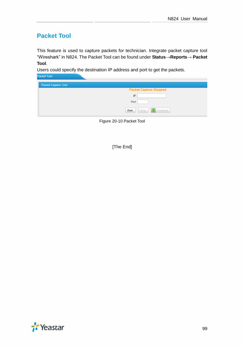
N824 User Manual
99
Packet Tool
This feature is used to capture packets for technician. Integrate packet capture tool
―Wireshark‖ in N824. The Packet Tool can be found under Status→Reports→ Packet
Tool.
Users could specify the destination IP address and port to get the packets.
Figure 20-10 Packet Tool
[The End]