Embed Size (px)
DESCRIPTION
M.Y.H. Bangash Structural Detailing in Steel 2000.pdf
Citation preview
Structural detailing in steel
A comparative study of British, Europeanand American codes and practices
M. Y. H. Bangash
Published by Thomas Telford Publishing, Thomas Telford Ltd, 1 Heron Quay,London E14 4JD.URL: http://www.t-telford.co.uk
Distributors for Thomas Telford books areUSA: ASCE Press, 1801 Alexander Bell Drive, Reston, VA 20191-4400,USAJapan: Maruzen Co. Ltd, Book Department, 3–10 Nihonbashi 2-chome,Chuo-ku, Tokyo 103Australia: DA Books and Journals, 648 Whitehorse Road, Mitcham 3132,Victoria
First published 2000
A catalogue record for this book is available from the British Library
ISBN: 0 7277 2850 4
© M. Y. H. Bangash, 2000
All rights, including translation, reserved. Except as permitted by theCopyright, Designs and Patents Act 1988, no part of this publication may bereproduced, stored in a retrieval system or transmitted in any form or by anymeans, electronic, mechanical, photocopying or otherwise, without the priorwritten permission of the Books Publisher, Thomas Telford Publishing,Thomas Telford Ltd, 1 Heron Quay, London E14 4JD.
This book is published on the understanding that the author is solelyresponsible for the statements made and opinions expressed in it and that itspublication does not necessarily imply that such statements and/or opinionsare or reflect the views or opinions of the publishers. While every effort hasbeen made to ensure that the statements made and the opinions expressed inthis publication provide a safe and accurate guide, no liability or responsibilitycan be accepted in this respect by the authors or publishers.
Typeset by APEK Digital Imaging, BristolPrinted and bound in Great Britain by MPG Books, Bodmin, Cornwall
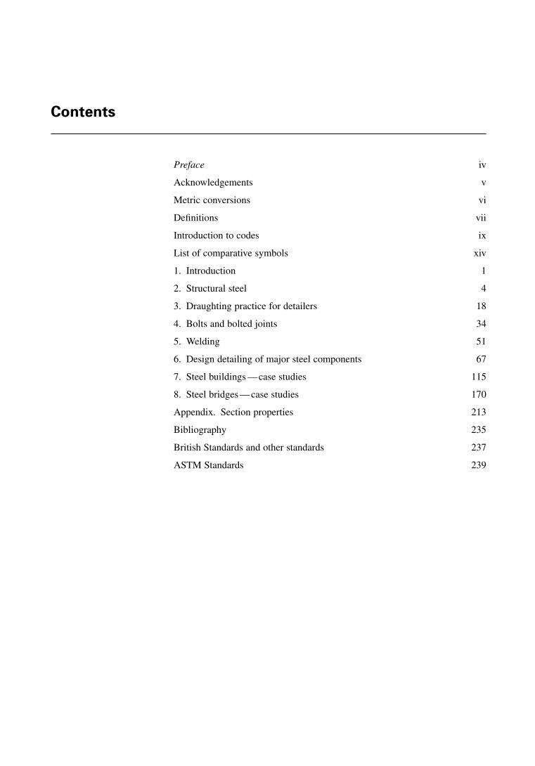
Contents
Preface iv
Acknowledgements v
Metric conversions vi
Definitions vii
Introduction to codes ix
List of comparative symbols xiv
1. Introduction 1
2. Structural steel 4
3. Draughting practice for detailers 18
4. Bolts and bolted joints 34
5. Welding 51
6. Design detailing of major steel components 67
7. Steel buildings — case studies 115
8. Steel bridges — case studies 170
Appendix. Section properties 213
Bibliography 235
British Standards and other standards 237
ASTM Standards 239
Preface
This steel detailing manual has been prepared to provide practical and up todate information on various aspects of steel construction for educators,designers, draughtsmen, detailers, fabricators and all others who have aninterest in structural steelwork.
The text covers the full scope of structural detailing in the UK, Europe andthe USA. The text covers the fundamentals of drawing, continuing withdraughting practice and connections, the types of fastenings and theconventional methods of detailing components. Individual case studies areincluded.
The types of structure covered represent the bulk of the typical fabricator’swork in commercial and industrial buildings, bridges, tanks, hydraulic andoffshore structures and power structures. Examples of steel detailing in CADformat are included in some of the chapters.
Many of the drawings included are typical and, with minimal alteration, canbe adopted directly from the book and attached to individual drawings basedon a special code.
This book should serve both as a primer for trainee detailers and as areference manual for more experienced personnel. Engineers, architects andcontractors will find the book useful for daily use and practice.
M. Y. H. Bangash
iv
STRUCTURAL DETAILING IN STEEL
Acknowledgements
The author acknowledges his appreciation to friends, colleagues and somestudents who have assisted in the early development of this book. The authorhas received a great deal of assistance and encouragement from the researchorganisations, engineering companies, consultants and constructors in steel-work and computer-aided design bureaus referred to in this book. The authoris particularly indebted to the following:
British Standards Institute, UKAmerican Institute of Steel Construction, USAEuropean Union Group for EC3 Code, Brussels, BelgiumAmerican State Highways and Transportation OfficialsAmerican Society for Testing of MaterialsHighway Agency, UKWard and Cole, Consultants, UKStrucad, Derby, UKSwindell Dresseler Corp., Pittsburgh, USAMaster Series, Northern Ireland, UKAmerican Society of Civil Engineers, USAThe Steel Construction Institute, UK
The author is extremely grateful to Mike Chrimes, the Chief Librarian of theInstitution of Civil Engineers, London for providing facilities and support tocomplete this book.
Certain valuable research materials were provided by the Institution ofStructural Engineers, London and they are acknowledged.
The author is especially indebted to Dr F. Bangash for the preparation ofartwork included in this text.
The author is grateful to Mr Shyam Shrestha of ASZ Partners, Ilford, fortaking the trouble to type the manuscript.
v
PREAMBLE
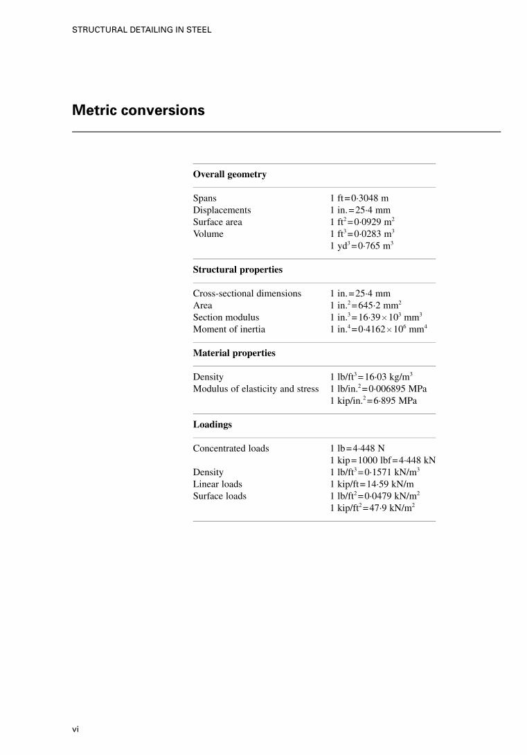
Metric conversions
Overall geometry
Spans 1 ft=0·3048 mDisplacements 1 in.=25·4 mmSurface area 1 ft2 =0·0929 m2
Volume 1 ft3 =0·0283 m3
1 yd3 =0·765 m3
Structural properties
Cross-sectional dimensions 1 in.=25·4 mmArea 1 in.2 =645·2 mm2
Section modulus 1 in.3 =16·39� 103 mm3
Moment of inertia 1 in.4 =0·4162� 106 mm4
Material properties
Density 1 lb/ft3 =16·03 kg/m3
Modulus of elasticity and stress 1 lb/in.2 =0·006895 MPa1 kip/in.2 =6·895 MPa
Loadings
Concentrated loads 1 lb=4·448 N1 kip=1000 lbf=4·448 kN
Density 1 lb/ft3 =0·1571 kN/m3
Linear loads 1 kip/ft=14·59 kN/mSurface loads 1 lb/ft2 =0·0479 kN/m2
1 kip/ft2 =47·9 kN/m2
vi
STRUCTURAL DETAILING IN STEEL
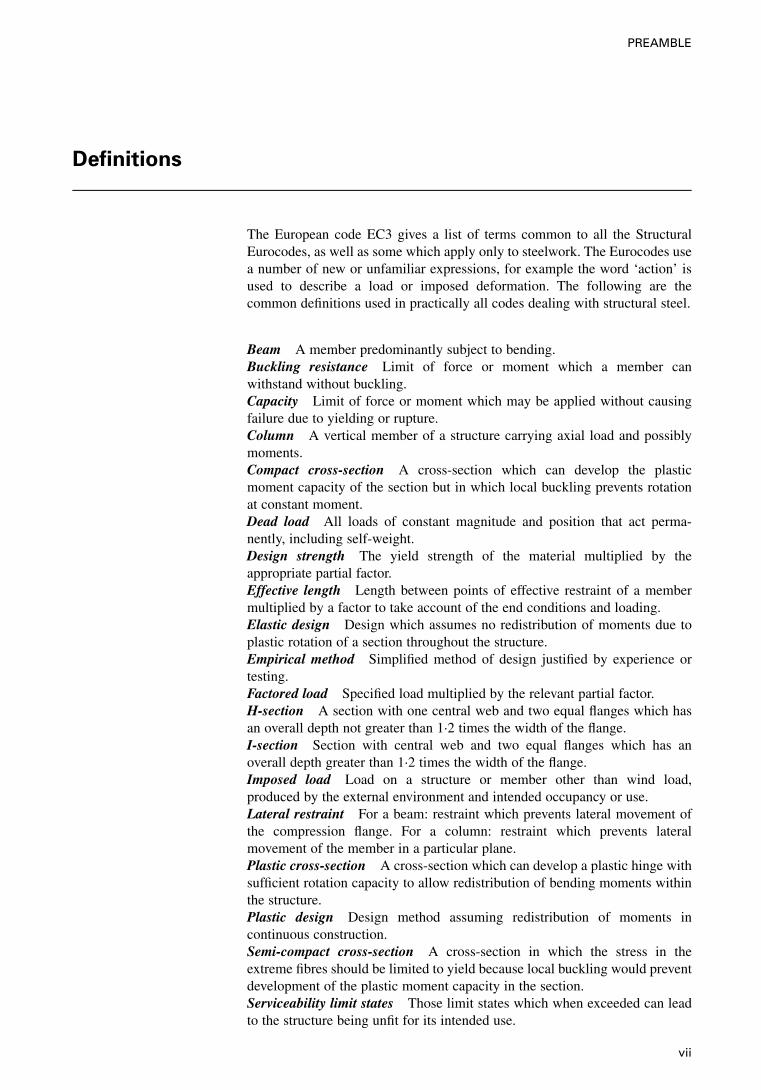
Definitions
The European code EC3 gives a list of terms common to all the StructuralEurocodes, as well as some which apply only to steelwork. The Eurocodes usea number of new or unfamiliar expressions, for example the word ‘action’ isused to describe a load or imposed deformation. The following are thecommon definitions used in practically all codes dealing with structural steel.
Beam A member predominantly subject to bending.Buckling resistance Limit of force or moment which a member canwithstand without buckling.Capacity Limit of force or moment which may be applied without causingfailure due to yielding or rupture.Column A vertical member of a structure carrying axial load and possiblymoments.Compact cross-section A cross-section which can develop the plasticmoment capacity of the section but in which local buckling prevents rotationat constant moment.Dead load All loads of constant magnitude and position that act perma-nently, including self-weight.Design strength The yield strength of the material multiplied by theappropriate partial factor.Effective length Length between points of effective restraint of a membermultiplied by a factor to take account of the end conditions and loading.Elastic design Design which assumes no redistribution of moments due toplastic rotation of a section throughout the structure.Empirical method Simplified method of design justified by experience ortesting.Factored load Specified load multiplied by the relevant partial factor.H-section A section with one central web and two equal flanges which hasan overall depth not greater than 1·2 times the width of the flange.I-section Section with central web and two equal flanges which has anoverall depth greater than 1·2 times the width of the flange.Imposed load Load on a structure or member other than wind load,produced by the external environment and intended occupancy or use.Lateral restraint For a beam: restraint which prevents lateral movement ofthe compression flange. For a column: restraint which prevents lateralmovement of the member in a particular plane.Plastic cross-section A cross-section which can develop a plastic hinge withsufficient rotation capacity to allow redistribution of bending moments withinthe structure.Plastic design Design method assuming redistribution of moments incontinuous construction.Semi-compact cross-section A cross-section in which the stress in theextreme fibres should be limited to yield because local buckling would preventdevelopment of the plastic moment capacity in the section.Serviceability limit states Those limit states which when exceeded can leadto the structure being unfit for its intended use.
vii
PREAMBLE

Slender cross-section A cross-section in which yield of the extreme fibrescannot be attained because of premature local buckling.Slenderness The effective length divided by the radius of gyration.Strength Resistance to failure by yielding or buckling.Strut A member of a structure carrying predominantly compressive axialload.Ultimate limit state That state which if exceeded can cause collapse of partor the whole of the structure.
viii
STRUCTURAL DETAILING IN STEEL
Introduction to codes
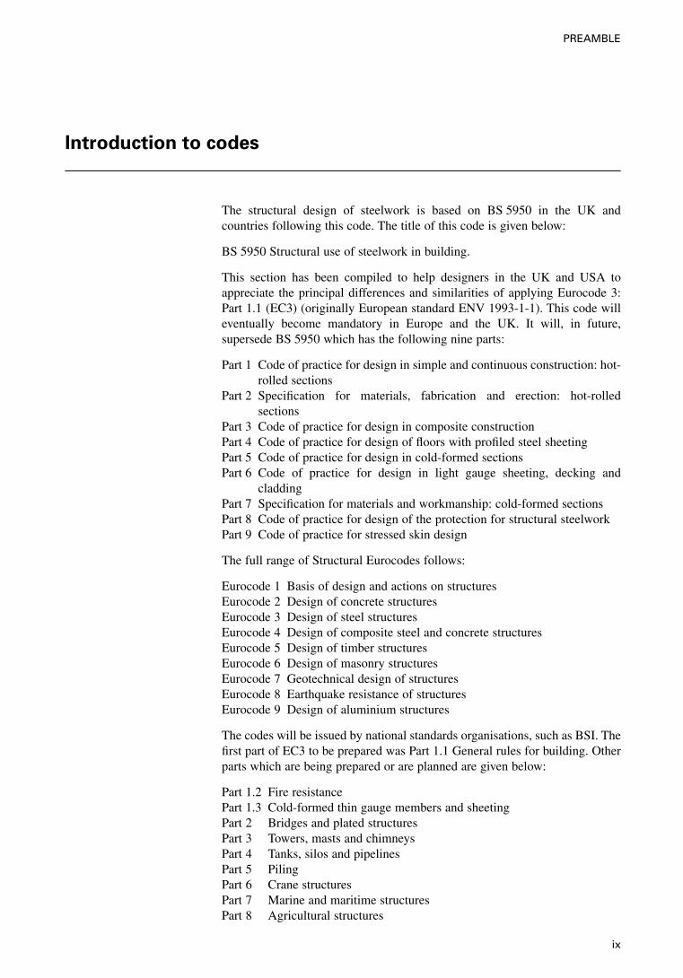
The structural design of steelwork is based on BS 5950 in the UK andcountries following this code. The title of this code is given below:
BS 5950 Structural use of steelwork in building.
This section has been compiled to help designers in the UK and USA toappreciate the principal differences and similarities of applying Eurocode 3:Part 1.1 (EC3) (originally European standard ENV 1993-1-1). This code willeventually become mandatory in Europe and the UK. It will, in future,supersede BS 5950 which has the following nine parts:
Part 1 Code of practice for design in simple and continuous construction: hot-rolled sections
Part 2 Specification for materials, fabrication and erection: hot-rolledsections
Part 3 Code of practice for design in composite constructionPart 4 Code of practice for design of floors with profiled steel sheetingPart 5 Code of practice for design in cold-formed sectionsPart 6 Code of practice for design in light gauge sheeting, decking and
claddingPart 7 Specification for materials and workmanship: cold-formed sectionsPart 8 Code of practice for design of the protection for structural steelworkPart 9 Code of practice for stressed skin design
The full range of Structural Eurocodes follows:
Eurocode 1 Basis of design and actions on structuresEurocode 2 Design of concrete structuresEurocode 3 Design of steel structuresEurocode 4 Design of composite steel and concrete structuresEurocode 5 Design of timber structuresEurocode 6 Design of masonry structuresEurocode 7 Geotechnical design of structuresEurocode 8 Earthquake resistance of structuresEurocode 9 Design of aluminium structures
The codes will be issued by national standards organisations, such as BSI. Thefirst part of EC3 to be prepared was Part 1.1 General rules for building. Otherparts which are being prepared or are planned are given below:
Part 1.2 Fire resistancePart 1.3 Cold-formed thin gauge members and sheetingPart 2 Bridges and plated structuresPart 3 Towers, masts and chimneysPart 4 Tanks, silos and pipelinesPart 5 PilingPart 6 Crane structuresPart 7 Marine and maritime structuresPart 8 Agricultural structures
ix
PREAMBLE
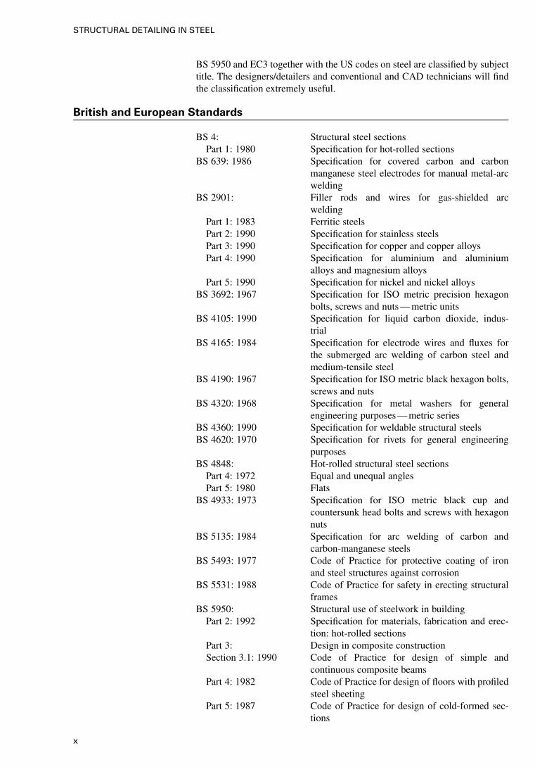
BS 5950 and EC3 together with the US codes on steel are classified by subjecttitle. The designers/detailers and conventional and CAD technicians will findthe classification extremely useful.
British and European Standards
BS 4: Structural steel sectionsPart 1: 1980 Specification for hot-rolled sections
BS 639: 1986 Specification for covered carbon and carbonmanganese steel electrodes for manual metal-arcwelding
BS 2901: Filler rods and wires for gas-shielded arcwelding
Part 1: 1983 Ferritic steelsPart 2: 1990 Specification for stainless steelsPart 3: 1990 Specification for copper and copper alloysPart 4: 1990 Specification for aluminium and aluminium
alloys and magnesium alloysPart 5: 1990 Specification for nickel and nickel alloys
BS 3692: 1967 Specification for ISO metric precision hexagonbolts, screws and nuts — metric units
BS 4105: 1990 Specification for liquid carbon dioxide, indus-trial
BS 4165: 1984 Specification for electrode wires and fluxes forthe submerged arc welding of carbon steel andmedium-tensile steel
BS 4190: 1967 Specification for ISO metric black hexagon bolts,screws and nuts
BS 4320: 1968 Specification for metal washers for generalengineering purposes — metric series
BS 4360: 1990 Specification for weldable structural steelsBS 4620: 1970 Specification for rivets for general engineering
purposesBS 4848: Hot-rolled structural steel sections
Part 4: 1972 Equal and unequal anglesPart 5: 1980 Flats
BS 4933: 1973 Specification for ISO metric black cup andcountersunk head bolts and screws with hexagonnuts
BS 5135: 1984 Specification for arc welding of carbon andcarbon-manganese steels
BS 5493: 1977 Code of Practice for protective coating of ironand steel structures against corrosion
BS 5531: 1988 Code of Practice for safety in erecting structuralframes
BS 5950: Structural use of steelwork in buildingPart 2: 1992 Specification for materials, fabrication and erec-
tion: hot-rolled sectionsPart 3: Design in composite constructionSection 3.1: 1990 Code of Practice for design of simple and
continuous composite beamsPart 4: 1982 Code of Practice for design of floors with profiled
steel sheetingPart 5: 1987 Code of Practice for design of cold-formed sec-
tions
x
STRUCTURAL DETAILING IN STEEL
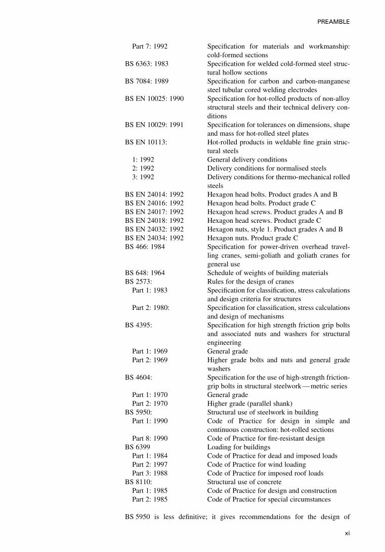
Part 7: 1992 Specification for materials and workmanship:cold-formed sections
BS 6363: 1983 Specification for welded cold-formed steel struc-tural hollow sections
BS 7084: 1989 Specification for carbon and carbon-manganesesteel tubular cored welding electrodes
BS EN 10025: 1990 Specification for hot-rolled products of non-alloystructural steels and their technical delivery con-ditions
BS EN 10029: 1991 Specification for tolerances on dimensions, shapeand mass for hot-rolled steel plates
BS EN 10113: Hot-rolled products in weldable fine grain struc-tural steels
1: 1992 General delivery conditions2: 1992 Delivery conditions for normalised steels3: 1992 Delivery conditions for thermo-mechanical rolled
steelsBS EN 24014: 1992 Hexagon head bolts. Product grades A and BBS EN 24016: 1992 Hexagon head bolts. Product grade CBS EN 24017: 1992 Hexagon head screws. Product grades A and BBS EN 24018: 1992 Hexagon head screws. Product grade CBS EN 24032: 1992 Hexagon nuts, style 1. Product grades A and BBS EN 24034: 1992 Hexagon nuts. Product grade CBS 466: 1984 Specification for power-driven overhead travel-
ling cranes, semi-goliath and goliath cranes forgeneral use
BS 648: 1964 Schedule of weights of building materialsBS 2573: Rules for the design of cranes
Part 1: 1983 Specification for classification, stress calculationsand design criteria for structures
Part 2: 1980: Specification for classification, stress calculationsand design of mechanisms
BS 4395: Specification for high strength friction grip boltsand associated nuts and washers for structuralengineering
Part 1: 1969 General gradePart 2: 1969 Higher grade bolts and nuts and general grade
washersBS 4604: Specification for the use of high-strength friction-
grip bolts in structural steelwork — metric seriesPart 1: 1970 General gradePart 2: 1970 Higher grade (parallel shank)
BS 5950: Structural use of steelwork in buildingPart 1: 1990 Code of Practice for design in simple and
continuous construction: hot-rolled sectionsPart 8: 1990 Code of Practice for fire-resistant design
BS 6399 Loading for buildingsPart 1: 1984 Code of Practice for dead and imposed loadsPart 2: 1997 Code of Practice for wind loadingPart 3: 1988 Code of Practice for imposed roof loads
BS 8110: Structural use of concretePart 1: 1985 Code of Practice for design and constructionPart 2: 1985 Code of Practice for special circumstances
BS 5950 is less definitive; it gives recommendations for the design of
xi
PREAMBLE

structural steelwork in buildings and allied structures not specifically coveredin other British Standards.
Eurocode 3: Part 1.1 contains general principles which are valid for all steelstructures as well as detailed application rules for ordinary buildings. Theremaining parts of the Eurocode will cover bridges and plated structures,towers, masts and chimneys, tanks, silos and pipelines, piling, cranestructures, marine and maritime structures, agricultural structures and fireresistance.
xii
STRUCTURAL DETAILING IN STEEL
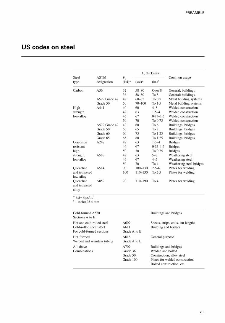
US codes on steel
Fu thicknessSteel ASTM Fy Common usagetype designation (ksi)* (ksi)* (in.)†
Carbon A36 32 58–80 Over 8 General; buildings36 58–80 To 8 General; buildings
A529 Grade 42 42 60–85 To 0·5 Metal building systemsGrade 50 50 70–100 To 1·5 Metal building systems
High- A441 40 60 4–8 Welded constructionstrength 42 63 1·5–4 Welded constructionlow-alloy 46 67 0·75–1·5 Welded construction
50 70 To 0·75 Welded constructionA572 Grade 42 42 60 To 6 Buildings; bridgesGrade 50 50 65 To 2 Buildings; bridgesGrade 60 60 75 To 1·25 Buildings; bridgesGrade 65 65 80 To 1·25 Buildings; bridges
Corrosion A242 42 63 1·5–4 Bridgesresistant 46 67 0·75–1·5 Bridgeshigh- 50 70 To 0·75 Bridgesstrength, A588 42 63 5–8 Weathering steellow-alloy 46 67 4–5 Weathering steel
50 70 To 4 Weathering steel bridgesQuenched A514 90 100–130 2·5–6 Plates for weldingand tempered 100 110–130 To 2·5 Plates for weldinglow-alloyQuenched A852 70 110–190 To 4 Plates for weldingand temperedalloy
* ksi=kips/in.2
† 1 inch=25·4 mm
Cold-formed A570Sections A to E
Buildings and bridges
Hot and cold-rolled steel A609 Sheets, strips, coils, cut lengthsCold-rolled sheet steel A611 Building and bridgesFor cold-formed sections Grade A to E
Hot-formed A618 General purposeWelded and seamless tubing Grade A to E
All above A709 Buildings and bridgesCombinations Grade 36 Welded and bolted
Grade 50 Construction, alloy steelGrade 100 Plates for welded construction
Bolted construction, etc.
xiii
PREAMBLE
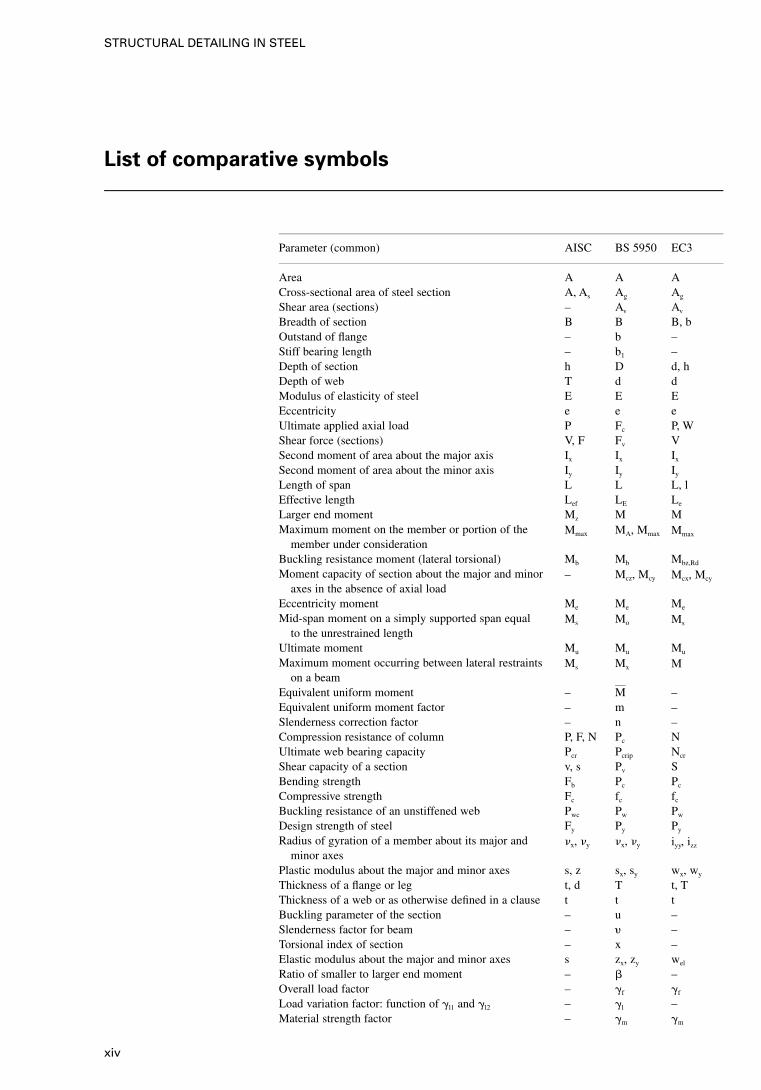
List of comparative symbols
Parameter (common) AISC BS 5950 EC3
Area A A ACross-sectional area of steel section A, As Ag Ag
Shear area (sections) – Av Av
Breadth of section B B B, bOutstand of flange – b –Stiff bearing length – b1 –Depth of section h D d, hDepth of web T d dModulus of elasticity of steel E E EEccentricity e e eUltimate applied axial load P Fc P, WShear force (sections) V, F Fv VSecond moment of area about the major axis Ix Ix Ix
Second moment of area about the minor axis Iy Iy Iy
Length of span L L L, lEffective length Lef LE Le
Larger end moment Mz M MMaximum moment on the member or portion of the
member under considerationMmax MA, Mmax Mmax
Buckling resistance moment (lateral torsional) Mb Mb Mbz,Rd
Moment capacity of section about the major and minoraxes in the absence of axial load
– Mcz, Mcy Mcx, Mcy
Eccentricity moment Me Me Me
Mid-span moment on a simply supported span equalto the unrestrained length
Ms Mo Ms
Ultimate moment Mu Mu Mu
Maximum moment occurring between lateral restraintson a beam
Ms Mx M
Equivalent uniform moment – M –Equivalent uniform moment factor – m –Slenderness correction factor – n –Compression resistance of column P, F, N Pc NUltimate web bearing capacity Pcr Pcrip Ncr
Shear capacity of a section v, s Pv SBending strength Fb Pc Pc
Compressive strength Fc fc fc
Buckling resistance of an unstiffened web Pwc Pw Pw
Design strength of steel Fy Py Py
Radius of gyration of a member about its major andminor axes
�x, �y �x, �y iyy, izz
Plastic modulus about the major and minor axes s, z sx, sy wx, wy
Thickness of a flange or leg t, d T t, TThickness of a web or as otherwise defined in a clause t t tBuckling parameter of the section – u –Slenderness factor for beam – � –Torsional index of section – x –Elastic modulus about the major and minor axes s zx, zy wel
Ratio of smaller to larger end moment – � –Overall load factor – �f �f
Load variation factor: function of �l1 and �l2 – �l –Material strength factor – �m �m
xiv
STRUCTURAL DETAILING IN STEEL

Parameter (common) AISC BS 5950 EC3
Ratio M/Mo that is the ratio of the larger end momentto the midspan moment on a simply supported span
– �D �D
Deflection D, a �, a �Constant (275/Py)
1/2 – � �Slenderness, that is the effective length divided by the
radius of gyrationc,
Equivalent slenderness – LT LT
Accidental action – – AArea A A ABolt force Ft, P F, P BCapacity; fixed value; factor – – CDamage (fatigue assessment) Fn – DModulus of elasticity E E EEffect of actions – – FAction – – FForce F, P F,P GPermanent action – – GShear modulus G G GTotal horizontal load or reaction H H HStiffness factor (I/L) K K KVariable action – – QResistance; reaction internal forces and moments (with
subscripts d or k)R R R, S
Stiffness (shear, rotational . . . stiffness with subscripts) K K, S STorsional moment; temperature T, Mt T, mt TShear force; total vertical load or reaction S S, V VSection modulus S, Z S WValue of a property of a material – – XDifference in . . . (precedes main symbol) – – Distance; geometrical data – – aThroat thickness of weld te, T, a – aArea ratio – – aDistance; outstand – – cDiameter; depth; length of diagonal – – dEccentricity; shift of centroidal axis al, e e eEdge distance; end distance – – eStrength (of a material) �, F � f, �Gap; width of a tension field – – gHeight H, h H, h hRadius of gyration; integer r r, i iCoefficient; factor – – kRatio of normal forces or normal stresses – – nNumber of .. – – nPitch; spacing p p pUniformly distributed force p, w, q w, q qRadius; root radius r, R r rStaggered pitch; distance p, g s sThickness d, t t, d tMajor axis x, x u, u uuMinor axis y, y �, � �, �Rectangular axes xx, yy xx, yy y, y, zzAngle; ratio; factor – – �Coefficient of linear thermal expansion � � �Angle; ratio; factor – � �Partial safety factor; ratio – – �Deflection; deformation D, �, �Coefficient (in Annex E) – – Angle; slope – – Slip factor; factor – – �Poisson’s ratio �, � � �Reduction factor; unit mass � � �
xv
PREAMBLE
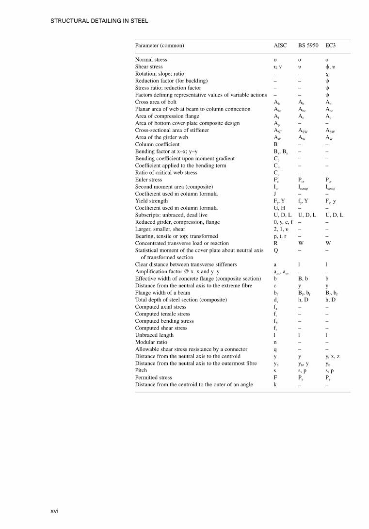
Parameter (common) AISC BS 5950 EC3
Normal stress � � �Shear stress �, v � �, �Rotation; slope; ratio – – �Reduction factor (for buckling) – – �Stress ratio; reduction factor – – �Factors defining representative values of variable actions – – �Cross area of bolt Ab Ab Ab
Planar area of web at beam to column connection Abc Abc Abc
Area of compression flange Af Ac Ac
Area of bottom cover plate composite design Ap – –Cross-sectional area of stiffener AST ASW ASW
Area of the girder web AW AW AW
Column coefficient B – –Bending factor at x–x; y–y Bx, By – –Bending coefficient upon moment gradient Cb – –Coefficient applied to the bending term Cm – –Ratio of critical web stress C� – –Euler stress F�c Pcr Pcr
Second moment area (composite) Itr Icomp Icomp
Coefficient used in column formula J – –Yield strength Fy, Y fy, Y Fy, yCoefficient used in column formula G, H – –Subscripts: unbraced, dead live U, D, L U, D, L U, D, LReduced girder, compression, flange 0, y, c, f – –Larger, smaller, shear 2, 1, � – –Bearing, tensile or top; transformed p, t, r – –Concentrated transverse load or reaction R W WStatistical moment of the cover plate about neutral axis
of transformed sectionQ – –
Clear distance between transverse stiffeners a l lAmplification factor @ x–x and y–y axx, ayy – –Effective width of concrete flange (composite section) b B, b bDistance from the neutral axis to the extreme fibre c y yFlange width of a beam bf Bf, bf Bf, bf
Total depth of steel section (composite) ds h, D h, DComputed axial stress fa – –Computed tensile stress ft – –Computed bending stress fb – –Computed shear stress fr – –Unbraced length l l lModular ratio n – –Allowable shear stress resistance by a connector q – –Distance from the neutral axis to the centroid y y y, x, zDistance from the neutral axis to the outermost fibre yb yb, y yb
Pitch s s, p s, pPermitted stress F Py Py
Distance from the centroid to the outer of an angle k – –
xvi
STRUCTURAL DETAILING IN STEEL
1. Introduction
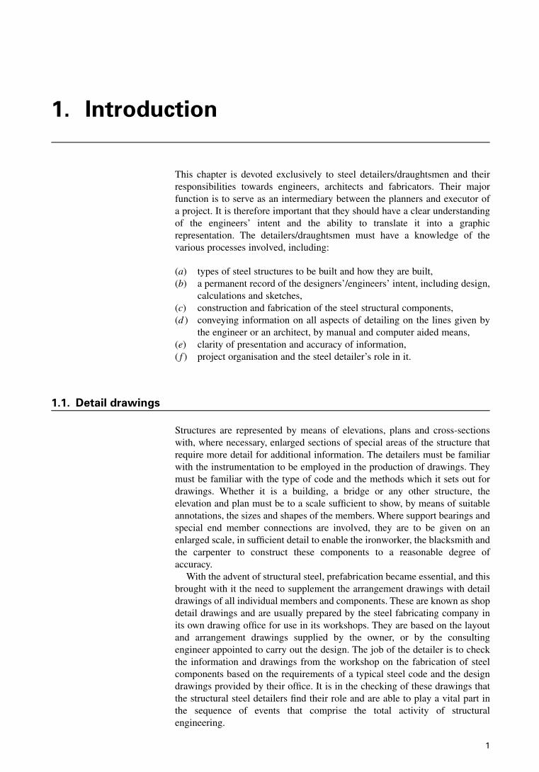
This chapter is devoted exclusively to steel detailers/draughtsmen and theirresponsibilities towards engineers, architects and fabricators. Their majorfunction is to serve as an intermediary between the planners and executor ofa project. It is therefore important that they should have a clear understandingof the engineers’ intent and the ability to translate it into a graphicrepresentation. The detailers/draughtsmen must have a knowledge of thevarious processes involved, including:
(a) types of steel structures to be built and how they are built,(b) a permanent record of the designers’/engineers’ intent, including design,
calculations and sketches,(c) construction and fabrication of the steel structural components,(d ) conveying information on all aspects of detailing on the lines given by
the engineer or an architect, by manual and computer aided means,(e) clarity of presentation and accuracy of information,( f ) project organisation and the steel detailer’s role in it.
1.1. Detail drawings
Structures are represented by means of elevations, plans and cross-sectionswith, where necessary, enlarged sections of special areas of the structure thatrequire more detail for additional information. The detailers must be familiarwith the instrumentation to be employed in the production of drawings. Theymust be familiar with the type of code and the methods which it sets out fordrawings. Whether it is a building, a bridge or any other structure, theelevation and plan must be to a scale sufficient to show, by means of suitableannotations, the sizes and shapes of the members. Where support bearings andspecial end member connections are involved, they are to be given on anenlarged scale, in sufficient detail to enable the ironworker, the blacksmith andthe carpenter to construct these components to a reasonable degree ofaccuracy.
With the advent of structural steel, prefabrication became essential, and thisbrought with it the need to supplement the arrangement drawings with detaildrawings of all individual members and components. These are known as shopdetail drawings and are usually prepared by the steel fabricating company inits own drawing office for use in its workshops. They are based on the layoutand arrangement drawings supplied by the owner, or by the consultingengineer appointed to carry out the design. The job of the detailer is to checkthe information and drawings from the workshop on the fabrication of steelcomponents based on the requirements of a typical steel code and the designdrawings provided by their office. It is in the checking of these drawings thatthe structural steel detailers find their role and are able to play a vital part inthe sequence of events that comprise the total activity of structuralengineering.
1
The detailer should look for the following items:
(a) that shop drawings are correct with regard to stylised representationinvolving the use of standardised, abbreviated notation and specialsymbols,
(b) that the information transmitted is clearly given,(c) any variations that need to be discussed with the designer,(d ) where a large amount of technical data given, the detailer’s job involves
recording and conveying it in a simple and concise manner.
1.2. Function of the steelwork detailer
The role of the steelwork draughtsman or detailer will now be examined moreclosely. When the contract is placed with a steelwork fabricator, and assumingthat the steelwork detailer works for the fabricator, their duties can becategorised as follows.
(a) The consulting engineer’s drawings and specifications are passed on bythe company management to the drawing office, where the drawingoffice manager assesses the extent, complexity and time content of thejob.
(b) The section leader confers with a senior detailer/draughtsman whoconstitutes a team of draughtsmen on the basis of expertise in specificareas gained from experience in previous contracts.
(c) The first function is to prepare a list of steel materials from the layoutdrawings provided by the consulting engineer, enabling the contractor toreserve the items from stock or to place orders with steel merchants orsteel mills.
(d ) The detailers proceed with the preparation of the steel work detailingdrawings, providing an accurate representation of components ofstructures, namely, beams, girders, trusses, columns, bracings, stairways,platforms, rails, brackets, girts, purlins etc., and where other structuressuch as bridges, towers, tanks etc., are involved, these will followbroadly the same pattern.
(e) An experienced senior draughtsman or detailer must carefully supervisedrawings and carefully scrutinise them as a checker. It is essential tocorrect the errors at this stage, as the correction of errors duringfabrication in the shop or during erection on site will be infinitely moreexpensive. Draughtsmen should be critical of their own work, subcon-sciously acting as their own checker, to ensure that, to the best of theirability, their drawings are error-free.
( f ) The detail drawings are sent to the fabrication shop, where work is putin hand, drawing the material from stock, cutting it to exact length,drilling or punching the necessary holes and assembling the various partsby means of bolting or welding to make up the components orsubassemblies ready for transport to site.
( g) The drawing office, whether using a manual system or computer aidedfacilities, must now proceed with the preparation of erection drawings,showing steel framework in skeleton form (elevations, plans and cross-sections). These drawings should be checked by the senior detailer andendorsed by a qualified structural engineer. The steel erector will refer tothese drawings for the assembly of the structure on site. The position ofeach component is identified by a distinguishing erection mark. In thefabrication shop, such erection marks are hand-marked, painted ortagged onto the steel components.
2
STRUCTURAL DETAILING IN STEEL
(h) All drawings are updated to incorporate any revisions that have occurredduring the progress of the job and a complete set of prints is handed tothe engineer for filing. These serve as a record of the work and are usefulfor future reference.
1.3. Project organisation
It is important to consider the role of the detailer in the overall managementand technical organisation that is involved in the steel construction project.
(a) When the owner appoints the architect and engineer for the steel project,they shall carry out the following:(i) the architect prepares the preliminary planning and detailed
planning of drawings and specifications and sends them to thestructural engineer.
(ii) The structural engineer then prepares preliminary design drawingsand, with the help of quantity surveyors, indicates costs to thearchitects, or directly to the owners where architects are notinvolved.
(b) The detailer acts as a liaison between the engineer and the contractor,and is responsible, whether working for the engineer or steelworkcontractor, for the preparation of the general arrangement (GA)drawings, shop drawings and the erection drawings.
(c) The detailer liaises with the steelwork contractor during erection ofsteelwork on site, ensuring that the engineer/designer is fully informedon day-to-day erection problems, particularly non-compliance withdetailed drawings.
(d ) The detailer is responsible for keeping the log book and other recordingarrangements, including storing in an electronic or mechanical retrievalsystem, photocopying and recording.
3
INTRODUCTION
2. Structural steel
2.1. Introduction
In this chapter, the material with which the steel detailer is concerned, i.e.structural steel, will be considered. It is vital that detailers should be familiarwith the characteristics and properties of steel.
Steel is a man-made metal derived from iron, which is its major constituent.The remaining components are small quantities of other elements, some ofwhich derive from the raw materials used in steel making and some of whichare deliberately added to improve the quality of the steel. Steel is generallyused for the basic products of the steel mill, such as plates, sections and bars,from which the structural members are fabricated; these being beams, girders,columns, struts, ties or the many other components comprising a structure.Steel is used extensively for the framework of bridges, buildings, buses, cars,conveyors, cranes, pipelines, ships, storage tanks, towers, trucks and otherstructures.
Although composed almost entirely of iron, steel contains small amounts ofother chemical elements to produce desired physical properties such asstrength, hardness, ductility, toughness and corrosion resistance. Carbon is themost important of the other elements. Increasing the carbon content producesan increase in strength and hardness, but decreases the ductility and toughness.Manganese, silicon, copper, chromium, columbium, molybdenum, nickel,phosphorus, vanadium, zirconium and aluminium are some of the otherelements that may be added to structural steel. Hot-rolled structural steels maybe classified as carbon steels, high-strength low-alloy steels, and alloy steels.
The concepts of strength and ductility are illustrated in Fig. 2.1. If a steelspecimen is loaded in direct tension, from zero up to final rupture, and theextension of the specimen is measured, a curve can be plotted as shown. Thisis known as a stress–strain curve, i.e. the stress is plotted against the strain.
2.2. Steel sections
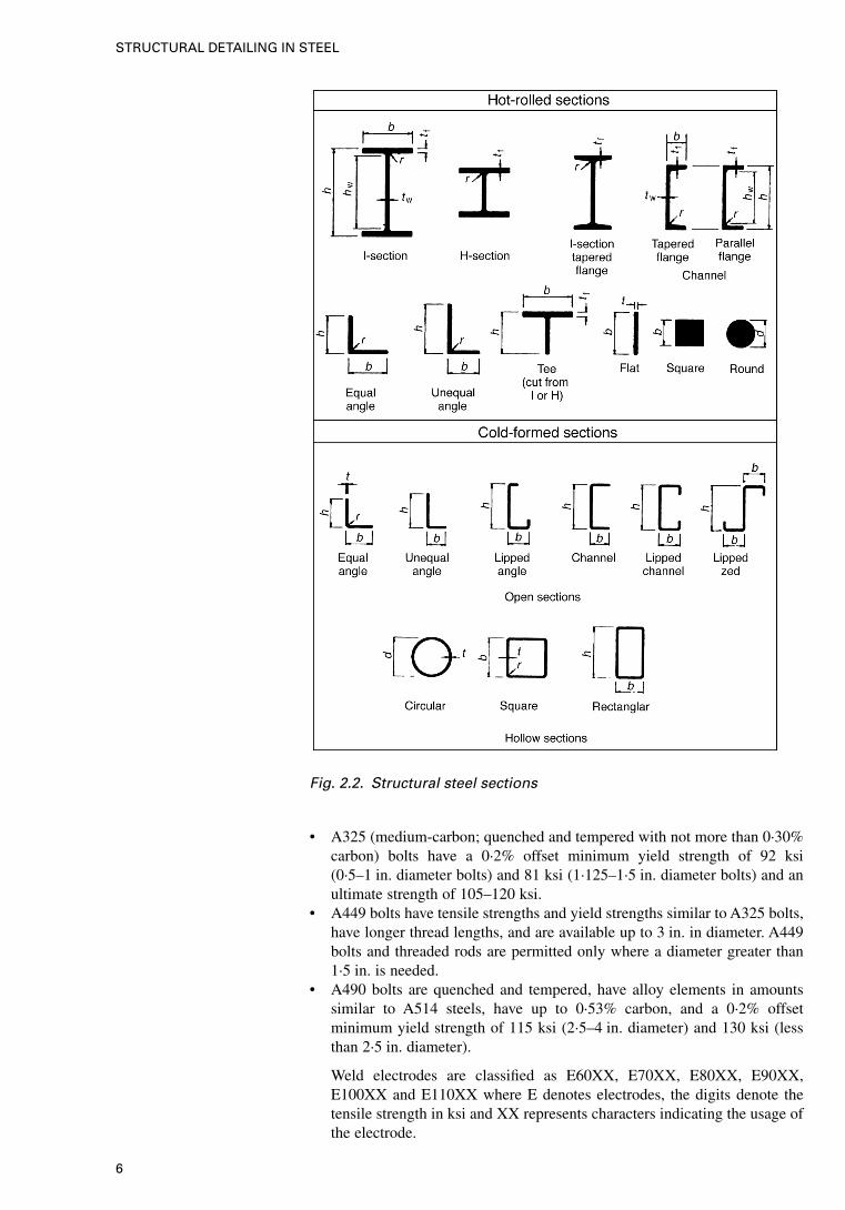
The forms in which steel is used in structures are I- and H-sections, channels,angles, flats, bars, plates, sheets, cold-formed sections and hollow sections.These descriptions apply to the cross-sectional shapes of the members, whichare shown in Fig. 2.2. It will be seen that there are two main classes; hot-rolledand cold-formed. The rolled sections are produced by passing a heated billetbetween successive pairs of rollers that squeeze the steel, stage by stage, intothe final shape. Hot-rolled plates are made in the same way, but here the rollersare flat and wide. The sections shown in Fig. 2.2 can be compounded toproduce different cross-sections.
Cold-formed sections are made by passing thin steel strips (not pre-heated)through sets of rollers that form the strip into the desired section by a bendingprocess. In the case of circular hollow sections, this is accompanied by acontinuous seam-welding process, whereby the abutting edges of the rolledsection are fused together. Rectangular hollow sections are formed fromcircular sections by a further cold-forming roller process. Therefore all cold-
4

formed hollow sections have a longitudinal seam weld running down their fulllength.
2.3. Steel quality
It is necessary for steel to be produced within acceptable quality limits toensure that it meets the requirements of a load-bearing material. These limitsinclude minimum strength and elongation requirements, maximum content ofvarious elements, etc. In various codes, these requirements are contained in aspecification. Structural steel is produced in a number of different strengthgrades. Different codes also have different designation labels. For example, inEC3 grade Fe 430 represents steel with a yield strength of 43 ksi, in ASTMspecifications A36 indicates carbon steel of a yield strength of 36 ksi and inBS 5950, grade 43 means carbon steel with a yield strength of 43 ksi.
2.4. Bolts and threaded fasteners and weld electrodes
2.4.1. US criteria The following classifications apply in the USA.
• A307 (low-carbon) bolts, usually referred to as common or machine orunfinished bolts, do not have a distinct yield point (minimum yield strengthof 60 ksi is taken at a strain of 0·002). Consequently, the Load andResistance Factor Design (LRFD) Specification does not permit these boltsto be used in a slip-critical connection (see LRFD J1.11, p. 6-72, J3.1,p. 6-79, and Table J3.2, p. 6-81). However, they may be used in a bearing-type connection.
Fig. 2.1. Stress–strain curve
5
STRUCTURAL STEEL
• A325 (medium-carbon; quenched and tempered with not more than 0·30%carbon) bolts have a 0·2% offset minimum yield strength of 92 ksi(0·5–1 in. diameter bolts) and 81 ksi (1·125–1·5 in. diameter bolts) and anultimate strength of 105–120 ksi.
• A449 bolts have tensile strengths and yield strengths similar to A325 bolts,have longer thread lengths, and are available up to 3 in. in diameter. A449bolts and threaded rods are permitted only where a diameter greater than1·5 in. is needed.
• A490 bolts are quenched and tempered, have alloy elements in amountssimilar to A514 steels, have up to 0·53% carbon, and a 0·2% offsetminimum yield strength of 115 ksi (2·5–4 in. diameter) and 130 ksi (lessthan 2·5 in. diameter).
Weld electrodes are classified as E60XX, E70XX, E80XX, E90XX,E100XX and E110XX where E denotes electrodes, the digits denote thetensile strength in ksi and XX represents characters indicating the usage ofthe electrode.
Fig. 2.2. Structural steel sections
6
STRUCTURAL DETAILING IN STEEL
2.4.2. BS 5950 and
EC3 criteria (UK
version)
The classifications which apply in the UK are as follows.
• High strength friction grip (ASFG) bolts used in close tolerance holes(+0·15–0 mm). They are of different grades or types:
° all grade 4·6 bolts — 20 mm diameter
° all grade 8·8 bolts — 24 mm diameter.• Black bolts grade 4·6 of mild steel based on BS 4190 (nuts and bolts) and
BS 4320 (washers). They are untensioned bolts in clearance holes 2 or 3mm larger than the bolt diameter.
• The HSFG bolts grade 8·8 are based on BS 3692 (nuts and bolts) andBS 4320 (washers).
The following provides additional performances and data:
(a) General grade (BS 4395, Part 1) bolts, nuts and washers with nooccurrence of slip and are used in the workshop and on site.
(b) Higher grade (BS 4395, Part 2) bolts, nuts and washers with clearanceholes and no occurrence of slip and are used in workshop and on site.
(c) Waisted shank (BS 4395, Part 3) bolts, nuts and washers with clearanceholes and non-occurrence of slip. A prestress of approximately 70% ofFu is induced in the shank of the bolts to bring the adjoining piles intocontact.
The mechanical properties of all these bolts are described in Chapter 4. Twomain types of weld are recommended: butt and fillet welds. Common weldprocesses are given below.
(d ) Manual metal arc (MMA) welds with a flux coating on the electrode.This process is manual and its main use is for short runs. Fillet weldslarger than 6 mm are usually multi-run and uneconomical. This processcan be employed both in the workshop and on site.
(e) Submerged arc (SUBARC) with power flux deposited over the arc. Thisis an automatic process and its main use is for long runs or heavy builtwelds. Either side of joints are welded simultaneously using twin heads.The recommended maximum weld size is 10 mm. This process can beused both in the workshop and on site.
( f ) Metal inert gas (MIG) with carbon dioxide gas generated. This processcan be automatic or semi-automatic. It replaces manual welding and isfor both short and long runs. The recommended maximum weld size is8 mm. This process is for the workshop only.
2.5. General properties
The Appendix gives properties of various steel sections based on three codes,namely BS 5950, EC3 and AISC. Some properties are given in Fig. 2.1. Thefollowing properties, shown in Table 2.1, are recommended in the absence ofexperimental tests for design and detailing at the tender stage.
7
STRUCTURAL STEEL
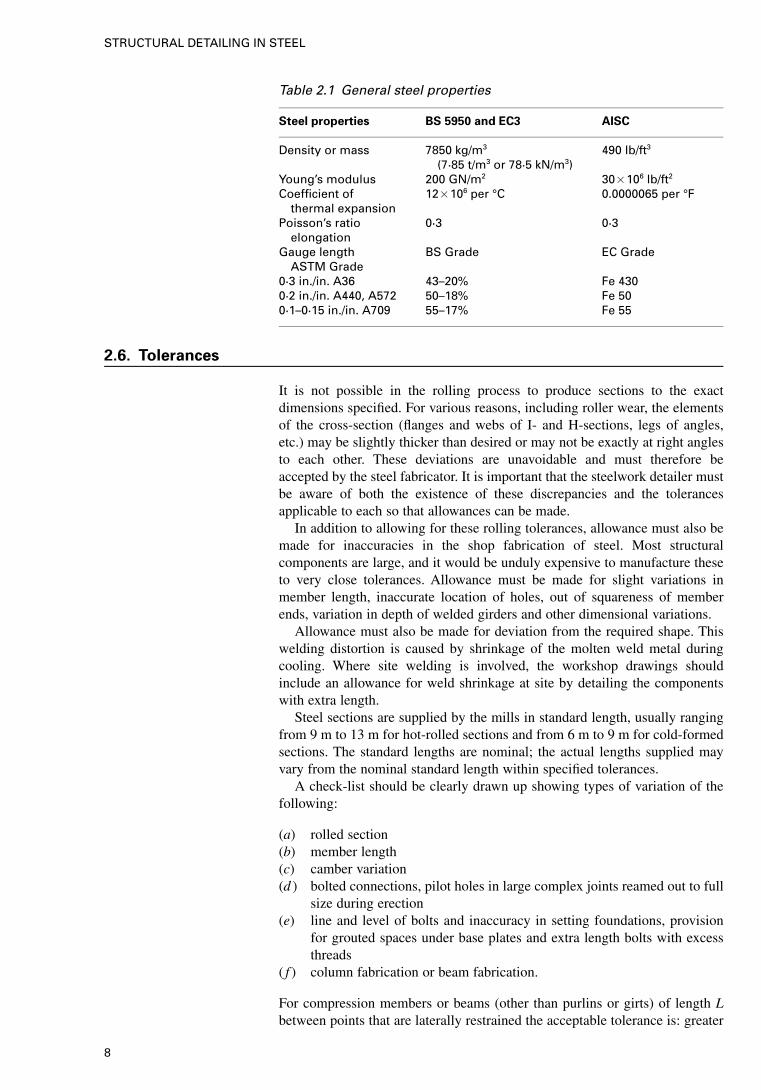
Table 2.1 General steel properties
Steel properties BS 5950 and EC3 AISC
Density or mass 7850 kg/m3
(7·85 t/m3 or 78·5 kN/m3)490 lb/ft3
Young’s modulus 200 GN/m2 30�106 lb/ft2
Coefficient ofthermal expansion
12�106 per °C 0.0000065 per °F
Poisson’s ratioelongation
0·3 0·3
Gauge lengthASTM Grade
BS Grade EC Grade
0·3 in./in. A36 43–20% Fe 4300·2 in./in. A440, A572 50–18% Fe 500·1–0·15 in./in. A709 55–17% Fe 55
2.6. Tolerances
It is not possible in the rolling process to produce sections to the exactdimensions specified. For various reasons, including roller wear, the elementsof the cross-section (flanges and webs of I- and H-sections, legs of angles,etc.) may be slightly thicker than desired or may not be exactly at right anglesto each other. These deviations are unavoidable and must therefore beaccepted by the steel fabricator. It is important that the steelwork detailer mustbe aware of both the existence of these discrepancies and the tolerancesapplicable to each so that allowances can be made.
In addition to allowing for these rolling tolerances, allowance must also bemade for inaccuracies in the shop fabrication of steel. Most structuralcomponents are large, and it would be unduly expensive to manufacture theseto very close tolerances. Allowance must be made for slight variations inmember length, inaccurate location of holes, out of squareness of memberends, variation in depth of welded girders and other dimensional variations.
Allowance must also be made for deviation from the required shape. Thiswelding distortion is caused by shrinkage of the molten weld metal duringcooling. Where site welding is involved, the workshop drawings shouldinclude an allowance for weld shrinkage at site by detailing the componentswith extra length.
Steel sections are supplied by the mills in standard length, usually rangingfrom 9 m to 13 m for hot-rolled sections and from 6 m to 9 m for cold-formedsections. The standard lengths are nominal; the actual lengths supplied mayvary from the nominal standard length within specified tolerances.
A check-list should be clearly drawn up showing types of variation of thefollowing:
(a) rolled section(b) member length(c) camber variation(d ) bolted connections, pilot holes in large complex joints reamed out to full
size during erection(e) line and level of bolts and inaccuracy in setting foundations, provision
for grouted spaces under base plates and extra length bolts with excessthreads
( f ) column fabrication or beam fabrication.
For compression members or beams (other than purlins or girts) of length Lbetween points that are laterally restrained the acceptable tolerance is: greater
8
STRUCTURAL DETAILING IN STEEL
of 3 mm or L/1000; for other members of length L: lesser of 25 mm orL/500.
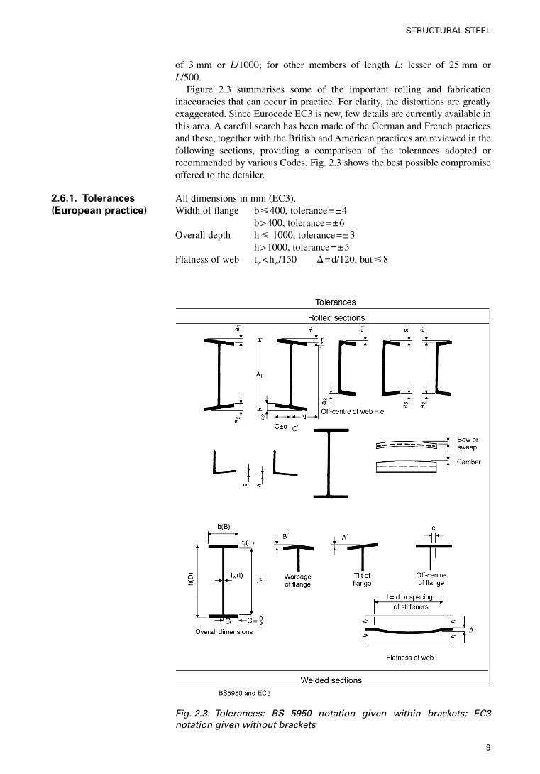
Figure 2.3 summarises some of the important rolling and fabricationinaccuracies that can occur in practice. For clarity, the distortions are greatlyexaggerated. Since Eurocode EC3 is new, few details are currently available inthis area. A careful search has been made of the German and French practicesand these, together with the British and American practices are reviewed in thefollowing sections, providing a comparison of the tolerances adopted orrecommended by various Codes. Fig. 2.3 shows the best possible compromiseoffered to the detailer.
2.6.1. Tolerances
(European practice)
All dimensions in mm (EC3).Width of flange b�400, tolerance=±4
b>400, tolerance=±6Overall depth h� 1000, tolerance=±3
h>1000, tolerance=±5Flatness of web tw <hw/150 �=d/120, but�8
Fig. 2.3. Tolerances: BS 5950 notation given within brackets; EC3notation given without brackets
9
STRUCTURAL STEEL
tw �hw/150 �=d/150, but�8e=6, A�=b/200, B�=b/200
Fabrication tolerancesThe straightness tolerances specified in Table 7.2 of EC3 have been assumedin the derivation of the design rules for the relevant type of member. Where thecurvature exceeds these values, the additional curvature shall be allowed in thedesign calculations. The straightness has a permitted deviation between±0.001L and ±0.002L.
2.6.2. Tolerances
(British practice)
All dimensions in accordance with BS 5950 and BS 4.Referring to Fig. 2.3, the rolled sections, their tolerances and effects indetailing are summarised as follows.
Beams, channels and columnsh at the centre line of the web from top flange.
Tolerances ±3·2; h up to 305+3·2�0·8>305 up to 406+4·0�1·6>406 +4·8�1·6
Flange width b+6·4�4·8 from the centre line of web
Off-centre ‘e’ of the web and dimension A1
h=102 up to 305 e=3·2 A1 =h+4·8h>305 e=4·8 A1 =h+6·4
c�=tw/2+2 mmN�=c–c�+6 mmN=(h�d)/2
Out of squareness (K=a1 +a2) Kb=up to 102 1·6b=102 up to 203 3·2b=203 up to 305 4·8b>305 6·4
Specified weight(Channel) based on BS 4
Flats and plates—EC3 (BS 5950)Overall end plates from the centre line of cross-section to top flange:
Thickness Width of flats/thick Width of plates Length of end platesUp to 10 0·4/t0 35→0·5 0·5 +0, –3
>40 0·8/t0 150→1·5 1·0 width 2%>5 mm ±4 lapped only>80 1·0 1·3
Additional items:
Cross-section Camber b/150 �=d/150; L/1000BowStraightness L/100�3 mm
A1 with b=450 +6>450 +9
The erection tolerances specified in Table 7.1 of EC3 apply to the followingreference points:
• for a column, the actual centre point of the column at each floor level andat the base, excluding any base-plate or cap-plate
10
STRUCTURAL DETAILING IN STEEL
• for a beam, the actual centre point of the top surface at each end of thebeam, excluding any end-plate.
Table 2.2. Normal tolerances after erection
Criterion Permitted deviation
Deviation of distance betweenadjacent columns
±5 mm
Inclination of a column in a multi-storey building between adjacentfloor levels
0·002hWhere h is the storey height
Deviation of a column’s location in amulti-storey building at any floorlevel, from a vertical line through theintended location of the column base
0·0035h/n0·5
Where h is the total height from thebase to the floor level concernedAnd n is the number of storeys fromthe base to the floor level concerned
Inclination of a column in a singlestorey building, (not supporting acrane gantry) other than a portalframe
0·0035hWhere h is the height of the column
Inclination of the column of a portalframe (not supporting a crane gantry)
Mean: 0·002hIndividual: 0·010h
The extracts from DD ENV 1993 Part 1.1 are reproduced with the permission ofBSI under licence number 2000SK/0364.
Position of holding down bolts
(a) Tolerances shall be specified for the positional deviations of the holdingdown bolts which will enable the tolerance limits for erection ofsteelwork to be satisfied.
(b) Tolerances shall be specified for the levels of the holding down boltswhich enable the specified tolerances to be satisfied for the followingcriteria:• the level of the base plate• the thickness of the bedding material under the base plate• the protrusion of the bolt through the nut• the number of threads clear below the nut.
(c) The deviations of the spacing between individual bolts within the groupof holding down bolts for each member shall not exceed the following:• for bolts rigidly cast in, between centres of bolts: ±5 mm• for bolts set in sleeves, between centres of sleeves: ±10 mm
2.6.3. Tolerances
based on US code
(American Institute ofSteel Construction—AISC)
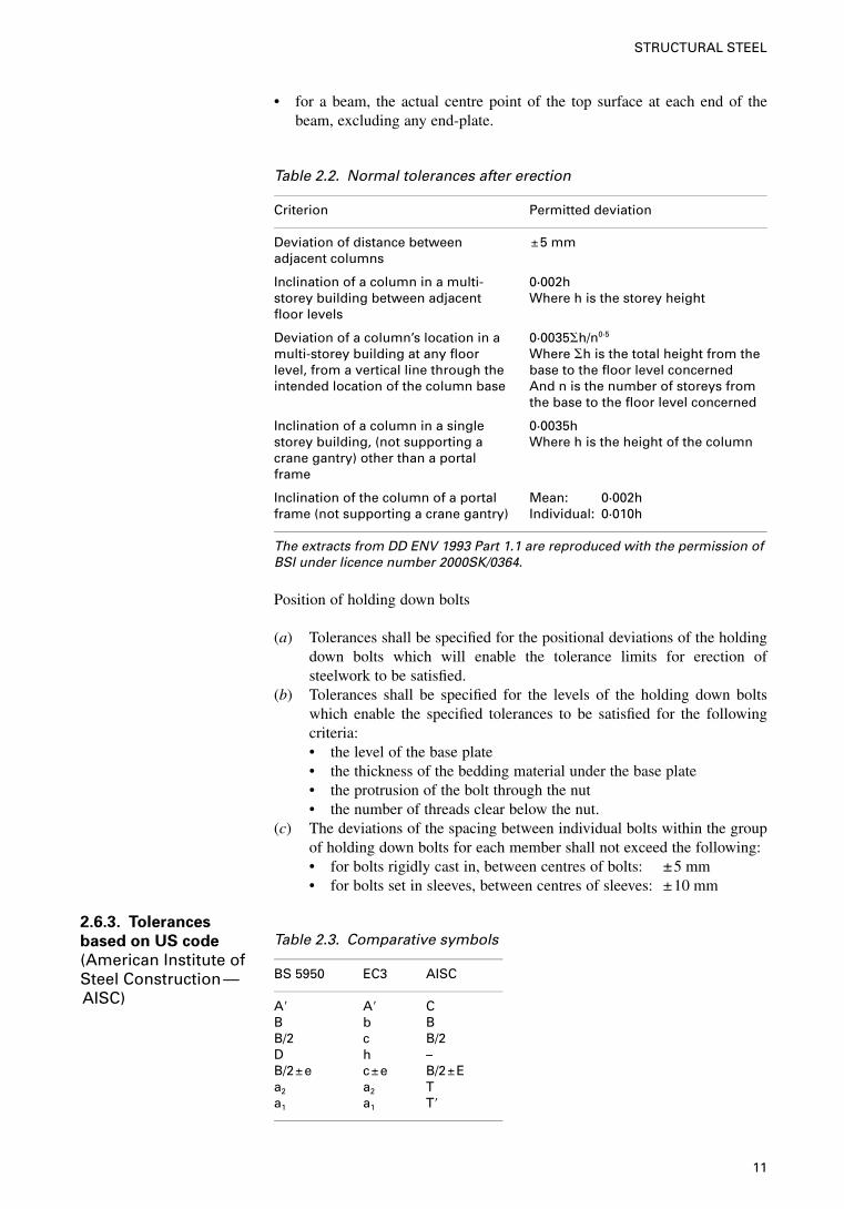
Table 2.3. Comparative symbols
BS 5950 EC3 AISC
A� A� CB b BB/2 c B/2D h –B/2±e c±e B/2±Ea2 a2 Ta1 a1 T�
11
STRUCTURAL STEEL
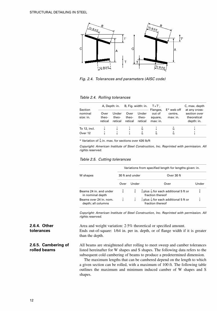
Fig. 2.4. Tolerances and parameters (AISC code)
Table 2.4. Rolling tolerances
A, Depth: in. B, Fig. width: in. T+T�, C, max. depthSection Flanges, E* web off at any cross-nominal Over Under Over Under out of centre, section oversize: in. theo- theo- theo- theo- square, max: in. theoretical
retical retical retical retical max: in. depth: in.
To 12, incl. 18
18
14
316
14
316
14
Over 12 18
18
14
316
516
316
14
* Variation of 516 in. max. for sections over 426 lb/ft
Copyright: American Institute of Steel Construction, Inc. Reprinted with permission. Allrights reserved.
Table 2.5. Cutting tolerances
Variations from specified length for lengths given: in.
W shapes 30 ft and under Over 30 ft
Over Under Over Under
Beams 24 in. and underin nominal depth
38
38
38 plus 1
16 for each additional 5 ft orfraction thereof
38
Beams over 24 in. nom.depth; all columns
12
12
12 plus 1
16 for each additional 5 ft orfraction thereof
12
Copyright: American Institute of Steel Construction, Inc. Reprinted with permission. Allrights reserved.
2.6.4. Other
tolerances
Area and weight variation: 2·5% theoretical or specified amount.Ends out-of-square: 1/64 in. per in. depth, or of flange width if it is greaterthan the depth.
2.6.5. Cambering of
rolled beams
All beams are straightened after rolling to meet sweep and camber toleranceslisted hereinafter for W shapes and S shapes. The following data refers to thesubsequent cold cambering of beams to produce a predetermined dimension.
The maximum lengths that can be cambered depend on the length to whicha given section can be rolled, with a maximum of 100 ft. The following tableoutlines the maximum and minimum induced camber of W shapes and Sshapes.
12
STRUCTURAL DETAILING IN STEEL
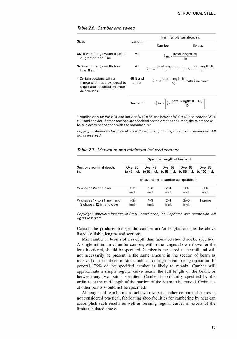
Table 2.6. Camber and sweep
Permissible variation: in.Sizes Length
Camber Sweep
Sizes with flange width equal toor greater than 6 in.
All 18 in.�
(total length: ft)10
Sizes with flange width lessthan 6 in.
All 18 in.�
(total length: ft)10
18 in.�
(total length: ft)5
* Certain sections with aflange width approx. equal todepth and specified on orderas columns
45 ft andunder
18 in.�
(total length: ft)10
with 38 in. max.
Over 45 ft 38 in.+�1
8 �(total length: ft�45)
10 �* Applies only to: W8 x 31 and heavier. W12 x 65 and heavier, W10 x 49 and heavier, W14x 90 and heavier. If other sections are specified on the order as columns, the tolerance willbe subject to negotiation with the manufacturer.
Copyright: American Institute of Steel Construction, Inc. Reprinted with permission. Allrights reserved.
Table 2.7. Maximum and minimum induced camber
Specified length of beam: ft
Sections nominal depth: Over 30 Over 42 Over 52 Over 65 Over 85in: to 42 incl. to 52 incl. to 65 incl. to 85 incl. to 100 incl.
Max. and min. camber acceptable: in.
W shapes 24 and over 1–2incl.
1–3incl.
2–4incl.
3–5incl.
3–6incl.
W shapes 14 to 21, incl. andS shapes 12 in. and over
34–21
2
incl.1–3incl.
2–4incl.
212–5
incl.Inquire
Copyright: American Institute of Steel Construction, Inc. Reprinted with permission. Allrights reserved.
Consult the producer for specific camber and/or lengths outside the abovelisted available lengths and sections.
Mill camber in beams of less depth than tabulated should not be specified.A single minimum value for camber, within the ranges shown above for thelength ordered, should be specified. Camber is measured at the mill and willnot necessarily be present in the same amount in the section of beam asreceived due to release of stress induced during the cambering operation. Ingeneral, 75% of the specified camber is likely to remain. Camber willapproximate a simple regular curve nearly the full length of the beam, orbetween any two points specified. Camber is ordinarily specified by theordinate at the mid-length of the portion of the beam to be curved. Ordinatesat other points should not be specified.
Although mill cambering to achieve reverse or other compound curves isnot considered practical, fabricating shop facilities for cambering by heat canaccomplish such results as well as forming regular curves in excess of thelimits tabulated above.
13
STRUCTURAL STEEL
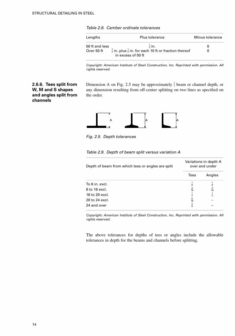
Table 2.8. Camber ordinate tolerances
Lengths Plus tolerance Minus tolerance
50 ft and less 12 in. 0
Over 50 ft 12 in. plus 18 in. for each 10 ft or fraction thereof
in excess of 50 ft0
Copyright: American Institute of Steel Construction, Inc. Reprinted with permission. Allrights reserved.
2.6.6. Tees split from
W, M and S shapes
and angles split from
channels
Dimension A on Fig. 2.5 may be approximately 12 beam or channel depth, or
any dimension resulting from off-center splitting on two lines as specified onthe order.
Fig. 2.5. Depth tolerances
Table 2.9. Depth of beam split versus variation A
Variations in depth ADepth of beam from which tees or angles are split over and under
Tees Angles
To 6 in. excl. 18
18
6 to 16 excl. 316
316
16 to 20 excl. 14
14
20 to 24 excl. 516 –
24 and over 38 –
Copyright: American Institute of Steel Construction, Inc. Reprinted with permission. Allrights reserved.
The above tolerances for depths of tees or angles include the allowabletolerances in depth for the beams and channels before splitting.
14
STRUCTURAL DETAILING IN STEEL
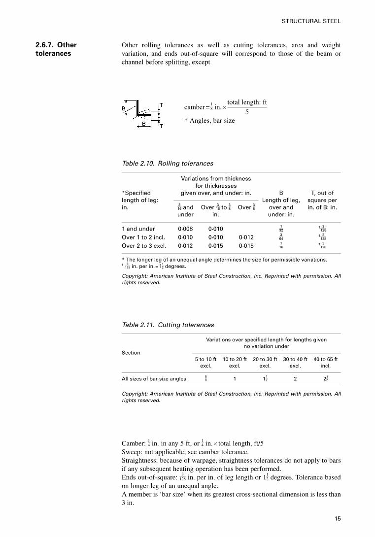
2.6.7. Other
tolerances
Other rolling tolerances as well as cutting tolerances, area and weightvariation, and ends out-of-square will correspond to those of the beam orchannel before splitting, except
camber= 18 in.�
total length: ft
5* Angles, bar size
Table 2.10. Rolling tolerances
Variations from thicknessfor thicknesses
*Specified given over, and under: in. B T, out oflength of leg: Length of leg, square perin. 3
16 andunder
Over 316 to 38
in.Over 38 over and
under: in.in. of B: in.
1 and under 0·008 0·010 132
† 3128
Over 1 to 2 incl. 0·010 0·010 0·012 364
† 3128
Over 2 to 3 excl. 0·012 0·015 0·015 116
† 3128
* The longer leg of an unequal angle determines the size for permissible variations.† 3
128 in. per in.=112 degrees.
Copyright: American Institute of Steel Construction, Inc. Reprinted with permission. Allrights reserved.
Table 2.11. Cutting tolerances
Variations over specified length for lengths givenno variation under
Section5 to 10 ft
excl.10 to 20 ft
excl.20 to 30 ft
excl.30 to 40 ft
excl.40 to 65 ft
incl.
All sizes of bar-size angles 58 1 11
2 2 212
Copyright: American Institute of Steel Construction, Inc. Reprinted with permission. Allrights reserved.
Camber: 14 in. in any 5 ft, or 1
4 in.� total length, ft/5Sweep: not applicable; see camber tolerance.Straightness: because of warpage, straightness tolerances do not apply to barsif any subsequent heating operation has been performed.Ends out-of-square: 3
128 in. per in. of leg length or 112 degrees. Tolerance based
on longer leg of an unequal angle.A member is ‘bar size’ when its greatest cross-sectional dimension is less than3 in.
15
STRUCTURAL STEEL
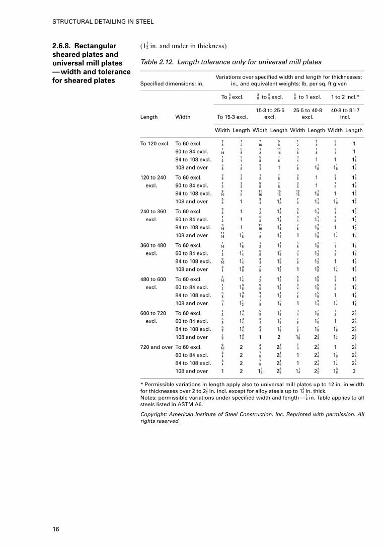
2.6.8. Rectangular
sheared plates and
universal mill plates
—width and tolerance
for sheared plates
(112 in. and under in thickness)
Table 2.12. Length tolerance only for universal mill plates
Variations over specified width and length for thicknesses:Specified dimensions: in. in., and equivalent weights: lb. per sq. ft given
To 38 excl. 38 to 58 excl. 5
8 to 1 excl. 1 to 2 incl.*
Length Width To 15·3 excl.15·3 to 25·5
excl.25·5 to 40·8
excl.40·8 to 81·7
incl.
Width Length Width Length Width Length Width Length
To 120 excl. To 60 excl. 38
12
716
58
12
34
58 1
60 to 84 excl. 716
58
12
1116
58
78
34 1
84 to 108 excl. 12
34
58
78
34 1 1 11
8
108 and over 58
78
34 1 7
8 118 11
8 114
120 to 240 To 60 excl. 38
34
12
78
58 1 3
4 118
excl. 60 to 84 excl. 12
34
58
78
34 1 7
8 114
84 to 108 excl. 916
78
1116
1516
1316 11
8 1 138
108 and over 58 1 3
4 118
78 11
4 118 13
8
240 to 360 To 60 excl. 38 1 1
2 118
58 11
434 11
2
excl. 60 to 84 excl. 12 1 5
8 118
34 11
478 11
2
84 to 108 excl. 916 1 11
16 118
78 13
8 1 122
108 and over 1116 11
878 11
4 1 138 11
4 134
360 to 480 To 60 excl. 716 11
812 11
458 13
834 15
8
excl. 60 to 84 excl. 12 11
458 13
834 11
278 15
8
84 to 108 excl. 916 11
434 13
878 11
2 1 178
108 and over 34 13
878 11
2 1 158 11
4 178
480 to 600 To 60 excl. 716 11
412 11
258 15
834 17
8
excl. 60 to 84 excl. 12 13
858 11
234 15
878 17
8
84 to 108 excl. 58 13
834 11
278 15
8 1 178
108 and over 34 11
278 15
8 1 134 11
4 178
600 to 720 To 60 excl. 12 13
458 17
834 17
878 21
4
excl. 60 to 84 excl. 58 13
434 17
878 17
8 1 214
84 to 108 excl. 58 13
434 17
878 17
8 118 21
4
108 and over 78 13
4 1 2 118 21
4 114 21
2
720 and over To 60 excl. 916 2 3
4 218
78 21
4 1 234
60 to 84 excl. 34 2 7
8 218 1 21
4 118 23
4
84 to 108 excl. 34 2 7
8 218 1 21
4 114 23
4
108 and over 1 2 118 23
8 114 21
2 138 3
* Permissible variations in length apply also to universal mill plates up to 12 in. in widthfor thicknesses over 2 to 21
2 in. incl. except for alloy steels up to 134 in. thick.
Notes: permissible variations under specified width and length— 14 in. Table applies to all
steels listed in ASTM A6.
Copyright: American Institute of Steel Construction, Inc. Reprinted with permission. Allrights reserved.
16
STRUCTURAL DETAILING IN STEEL
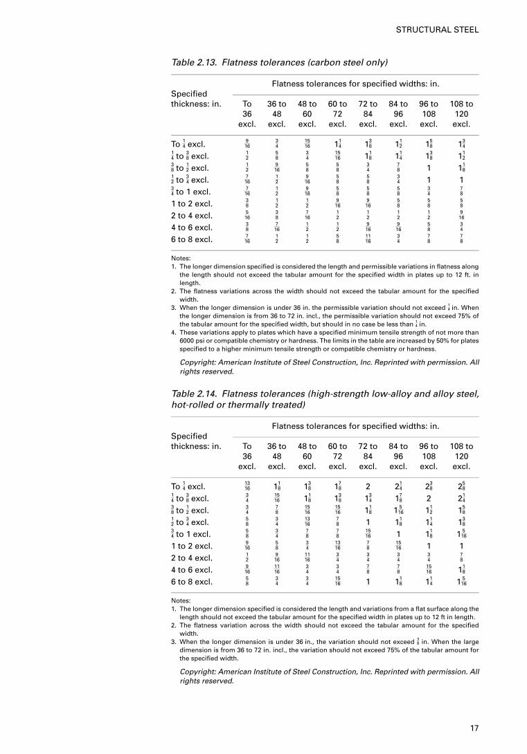
Table 2.13. Flatness tolerances (carbon steel only)
Flatness tolerances for specified widths: in.Specifiedthickness: in. To 36 to 48 to 60 to 72 to 84 to 96 to 108 to
36 48 60 72 84 96 108 120excl. excl. excl. excl. excl. excl. excl. excl.
To 14 excl. 916
34
1516 11
4 138 11
2 158 13
414 to 38 excl. 1
258
34
1516 11
8 114 13
8 112
38 to 12 excl. 1
2916
58
58
34
78 1 11
812 to 34 excl. 7
1612
916
58
58
34 1 1
34 to 1 excl. 7
1612
916
58
58
58
34
78
1 to 2 excl. 38
12
12
916
916
58
58
58
2 to 4 excl. 516
38
716
12
12
12
12
916
4 to 6 excl. 38
716
12
12
916
916
58
34
6 to 8 excl. 716
12
12
58
1116
34
78
78
Notes:1. The longer dimension specified is considered the length and permissible variations in flatness along
the length should not exceed the tabular amount for the specified width in plates up to 12 ft. inlength.
2. The flatness variations across the width should not exceed the tabular amount for the specifiedwidth.
3. When the longer dimension is under 36 in. the permissible variation should not exceed 14 in. When
the longer dimension is from 36 to 72 in. incl., the permissible variation should not exceed 75% ofthe tabular amount for the specified width, but should in no case be less than 1
4 in.4. These variations apply to plates which have a specified minimum tensile strength of not more than
6000 psi or compatible chemistry or hardness. The limits in the table are increased by 50% for platesspecified to a higher minimum tensile strength or compatible chemistry or hardness.
Copyright: American Institute of Steel Construction, Inc. Reprinted with permission. Allrights reserved.
Table 2.14. Flatness tolerances (high-strength low-alloy and alloy steel,hot-rolled or thermally treated)
Flatness tolerances for specified widths: in.Specifiedthickness: in. To 36 to 48 to 60 to 72 to 84 to 96 to 108 to
36 48 60 72 84 96 108 120excl. excl. excl. excl. excl. excl. excl. excl.
To 14 excl. 1316 11
8 138 17
8 2 214 23
8 258
14 to 38 excl. 3
41516 11
8 138 13
4 178 2 21
438 to 12 excl. 3
478
1516
1516 11
8 1 516 11
2 158
12 to 34 excl. 5
834
1316
78 1 11
8 114 13
834 to 1 excl. 5
834
78
78
1516 1 11
8 1 516
1 to 2 excl. 916
58
34
1316
78
1516 1 1
2 to 4 excl. 12
916
1116
34
34
34
34
78
4 to 6 excl. 916
1116
34
34
78
78
1516 11
8
6 to 8 excl. 58
34
34
1516 1 11
8 114 1 5
16
Notes:1. The longer dimension specified is considered the length and variations from a flat surface along the
length should not exceed the tabular amount for the specified width in plates up to 12 ft in length.2. The flatness variation across the width should not exceed the tabular amount for the specified
width.3. When the longer dimension is under 36 in., the variation should not exceed 3
8 in. When the largedimension is from 36 to 72 in. incl., the variation should not exceed 75% of the tabular amount forthe specified width.
Copyright: American Institute of Steel Construction, Inc. Reprinted with permission. Allrights reserved.
17
STRUCTURAL STEEL
3. Drafting practice for detailers
3.1. Introduction to the fundamentals of drafting
This chapter covers the fundamentals of the art of drafting. The primaryrequirement is drafting equipment, but various techniques are also needed forthe practical execution of different kinds of work, lettering, dimensions,symbols, line thickness, breaking lines, provision of match lines, scalingdetails, indication of bolts and bolt lines, indication of welding, orthographicprojections, elevation and section arrows and finally abbreviations. Theseelements are discussed here.
3.2. Equipment
All workshop detail drawings are made in pencil on tracing paper or on plasticdrafting film. These materials are transparent to enable copies or prints to bemade from the drawings by a dye-line printing process. In special cases,drawings are prepared in ink on drafting film, for durability. The equipmentrequired by the structural steelwork detailer is as follows:
(a) drawing board, furnished with a separate T-square, or a more elaboratedrafting system
(b) drawing paper or film (see Table 3.1 for drawing paper sizes)(c) pencils(d ) pencil sharpener(e) pens, supplied in point diameters (corresponding to the line thickness
required of 0.25 mm, 0.35 mm, 0.50 mm, 0.70 mm with each diameterbeing �2 times greater than the previous size
( f ) set squares — three set squares are sufficient for all drafting needs, viz.45° and 30°/60° fixed squares and an adjustable square giving angles of0° to 90°
( g) scales — two scales are usually required, one having 1 : 20, 1 : 25, 1 : 50and 1 : 100 reductions and the other 1 : 15, 1 : 30, 1 : 40 and 1 : 75reductions (EC3). In general, the following scales should be used: 1 : 5,1 : 10, 1 : 20, 1 : 25, 1 : 50, 1 : 100, 1 : 200
(h) protractor(i) compasses( j) circle template(k) eraser and shield(l ) french curves(m) calculator — a scientific electronic calculator is a necessary aid in the
summing of dimensions, the computation of bevel dimensions andbracing end clearances, and the calculation of steelwork masses onquantity lists
(n) computers — an increasing number of fabricators are using variouscomputer-aided drawing (CAD) programs to assist in the preparation of
18
layout and detail drawings. This is a highly specialised technique, butresults in significant time savings on larger contracts (see Fig. 3.1 for atypical CAD-based drawing office).
Table 3.1. Drawing sizes
Designation Size (mm) Size (in.)UK and Europe USA
A0* 1189�841 48�34A1* 841�594 34�24A2 594�420 24�16A3* 420�297 16�12A4* 297�210 12�8B1 1000�707 40�28
* Widely used.
3.3. Lettering, lines and dimensions/marks
No particular style of lettering is recommended but a number of practices haveindicated distinct uniform letters and figures that will produce decent copyprints. Stencils are used for viewing drawing titles. The computer-aidedtechniques can produce a number of different lettering schemes and symbols.In all cases, the clarity and uniformity of all symbols are the mainrequirements. Letters can either be upright or sloping at about 15°. Lower caselettering is used for general notations and upper case for headings, titles,sections and elevation arrows, etc. The minimum size of lettering in the UKand the USA is 2·5 mm and 3 mm respectively. All notes, letters, dimensionsand arrow heads used on plans, elevations, sketches and erection drawings areeither free hand or computer generated. See Figs 3.2 and 3.3 for typicalexamples of lettering.
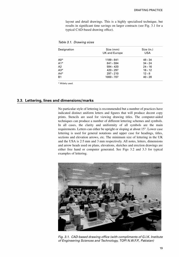
Fig. 3.1. CAD-based drawing office (with compliments of G.I.K. Instituteof Engineering Sciences and Technology, TOPI N.W.F.P., Pakistan)
19
DRAFTING PRACTICE
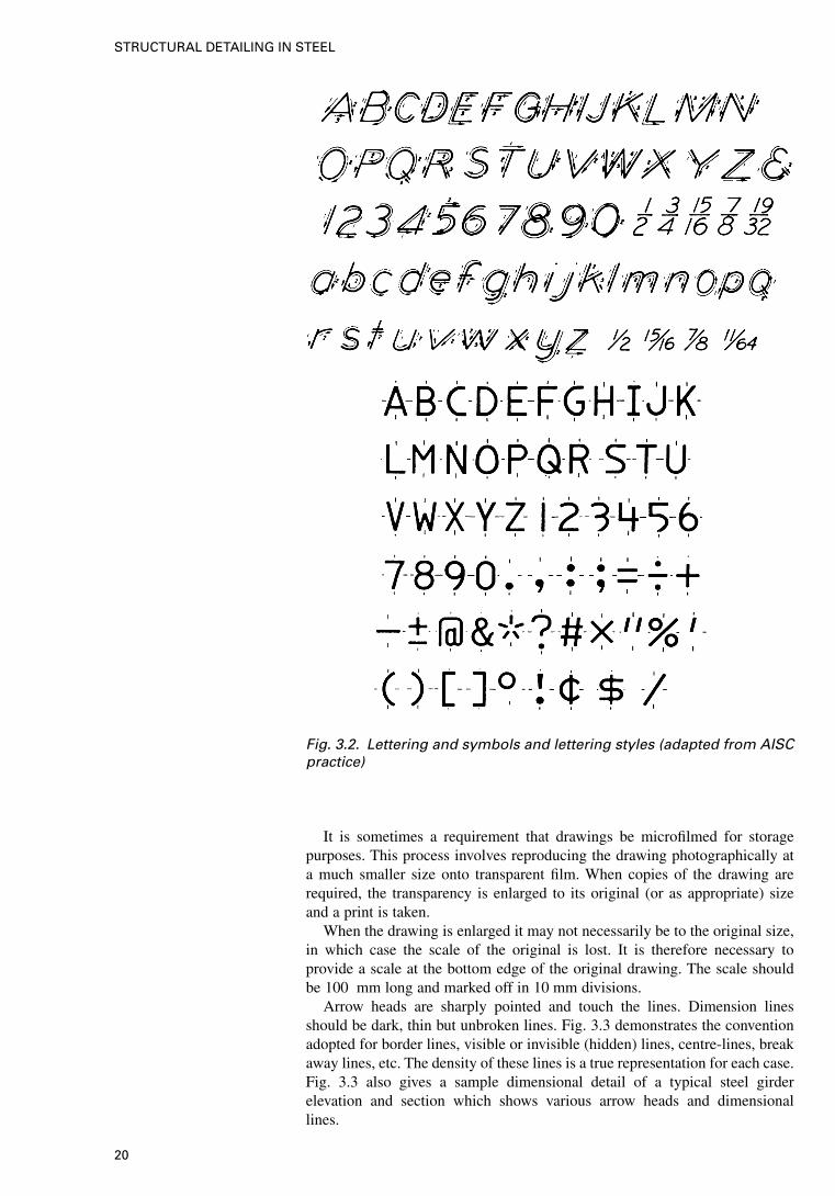
It is sometimes a requirement that drawings be microfilmed for storagepurposes. This process involves reproducing the drawing photographically ata much smaller size onto transparent film. When copies of the drawing arerequired, the transparency is enlarged to its original (or as appropriate) sizeand a print is taken.
When the drawing is enlarged it may not necessarily be to the original size,in which case the scale of the original is lost. It is therefore necessary toprovide a scale at the bottom edge of the original drawing. The scale shouldbe 100 mm long and marked off in 10 mm divisions.
Arrow heads are sharply pointed and touch the lines. Dimension linesshould be dark, thin but unbroken lines. Fig. 3.3 demonstrates the conventionadopted for border lines, visible or invisible (hidden) lines, centre-lines, breakaway lines, etc. The density of these lines is a true representation for each case.Fig. 3.3 also gives a sample dimensional detail of a typical steel girderelevation and section which shows various arrow heads and dimensionallines.
Fig. 3.2. Lettering and symbols and lettering styles (adapted from AISCpractice)
20
STRUCTURAL DETAILING IN STEEL
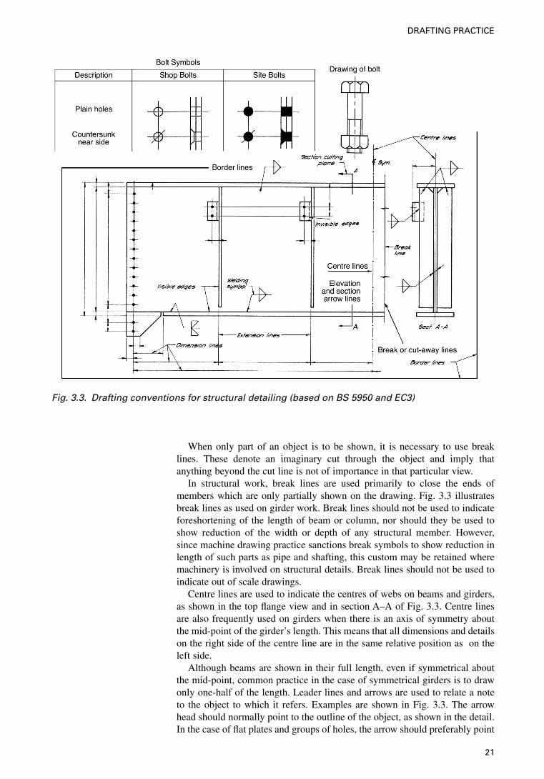
When only part of an object is to be shown, it is necessary to use breaklines. These denote an imaginary cut through the object and imply thatanything beyond the cut line is not of importance in that particular view.
In structural work, break lines are used primarily to close the ends ofmembers which are only partially shown on the drawing. Fig. 3.3 illustratesbreak lines as used on girder work. Break lines should not be used to indicateforeshortening of the length of beam or column, nor should they be used toshow reduction of the width or depth of any structural member. However,since machine drawing practice sanctions break symbols to show reduction inlength of such parts as pipe and shafting, this custom may be retained wheremachinery is involved on structural details. Break lines should not be used toindicate out of scale drawings.
Centre lines are used to indicate the centres of webs on beams and girders,as shown in the top flange view and in section A–A of Fig. 3.3. Centre linesare also frequently used on girders when there is an axis of symmetry aboutthe mid-point of the girder’s length. This means that all dimensions and detailson the right side of the centre line are in the same relative position as on theleft side.
Although beams are shown in their full length, even if symmetrical aboutthe mid-point, common practice in the case of symmetrical girders is to drawonly one-half of the length. Leader lines and arrows are used to relate a noteto the object to which it refers. Examples are shown in Fig. 3.3. The arrowhead should normally point to the outline of the object, as shown in the detail.In the case of flat plates and groups of holes, the arrow should preferably point
Fig. 3.3. Drafting conventions for structural detailing (based on BS 5950 and EC3)
21
DRAFTING PRACTICE
to the view showing the surface of the plate and the main view of the holes,and not to the plate edge.
On long members, particularly bridge girders, where the detail requiresmore than one sheet, it is customary to draw as much of the drawing as isconvenient on the first sheet of the series and continue the drawing onsuccessive sheets until the member is complete. The several sections of sucha member are related to one another by match lines. Match lines are usuallyestablished at a readily identifiable point, such as a stiffener gauge line or, forwelded work, the face of a bar stiffener. Match lines are tied by dimensions tothe closest dimensioned feature of all the views they cross. The ends of eachpair of match lines carry identical letters or numbers, such as X–X, Y–Y, 1–1,2–2, etc.
Bolts and bolt holes are shown in accordance with the symbols indicated inFig. 3.3. The diameters should be drawn to scale. Where bolts are of the high-strength friction-grip type, this should be clearly indicated by the note‘HSFG’. It will be seen that a distinction is made between shop bolts, whichare installed during assembly in the shop, and site bolts, which are usedto connect the components together during erection. In large scale details,where it is desirable to show the bolts for a particular reason, they may bedepicted.
Welding is indicated according to the standard symbols as shown in Fig.3.3. This is the most commonly used symbol. The welds are not usually shownon the drawing as the symbols are self-explanatory. Chapters 4 and 5 aredevoted to bolts and welding, including specification details.
Erection marks are needed for each separate or loose item that comes outof the workshop so that the item can be identified on site and erected in theright position. It is the detailer/draughtman’s responsibility to allocate thesemarks as the detailing proceeds. On beams, the mark should be located on thetop flange. On columns, the mark should be located on the lower end of theshaft on the flange.
Erection marks usually consist of prefix letters followed by the numbers (inconsecutive order) of the components. Standard prefixes are as follows:
B beams and girders KB kneebracesBK brackets P purlinsC column R raftersCG crane girders RB rafter bracing membersFR false rafters RG roof girdersG girts T trussesGG gantry girder VB vertical bracing members
In buildings with several floors, the beams may be further identified accordingto the floor they are to be on. For example, B/3/30 or B-3-30 would indicatebeam no. 30 on the third floor and C/5/39 or C-5-39 column no. 39 on the fifthfloor.
Another convention sometimes used is to allocate even numbers to beamsrunning in, say, a north–south direction and odd numbers to beams runningeast–west. This is of considerable assistance to the erector, who can readilyidentify the location of each beam in the floor.
3.4. Specified codes, specifications and detailing of drawings
3.4.1. Composition of
a typical structure
The detailer must be briefed on the structure, its design under a specific codeand be given a comprehensive guide regarding its composition when drawing
22
STRUCTURAL DETAILING IN STEEL
elevations, plans and cross-sections. The drawing should show the structure asit will appear when erected on site. The detailer will be required to draw eachcomponent separately with descriptive notation.
3.4.2. Design loading
and methods of
analysis
It is necessary for the detailer to have a basic understanding of how the designloading on a structure is derived and specified, to enable him to interpretcorrectly the loads and forces given on engineers’ drawings and to use themin designing connections. Loading such as self-weight, imposed loading, windloading, etc. that the structure must be capable of sustaining are termednominal loading.
The modern method of structural design is called limit-state design, whichmeans that the structure is designed to resist the applied loading under twolimiting conditions or states. These are the ultimate and the serviceability limitstates.
(a) Ultimate limit state — this is the state at which the structure or any partof it is just at the point of collapse or failure when subjected to acombination of applied loads; these loads being the nominal loadsmultiplied by appropriate factors.
(b) Serviceability limit state — this is the state beyond which the structure orany part of it no longer performs acceptably under the applicablecombination of nominal (not ultimate) loading, i.e. in its normal use orfunction.
3.4.3. Information
provided by the
engineer
It is at this stage that the steelwork detailer receives all the data required toproceed with the task of preparing the workshop drawings. The information isusually provided by the design engineer in the form of general arrangementdrawings and a brief specification. The drawings will include a layout of thestructure and typical connection details.
It is essential that the information provided is complete and explicit. Thepreparation of shop drawings is an activity lying on the critical path, whichmeans that any delay in the execution of this task will contribute to anextension of the time required to complete the entire steelwork project. Thefollowing information would be required by the detailer/draughtsman from thedesign engineer.
(a) General arrangement (i.e. layout) drawings, preferably to scale,including elevations, sections and plans, giving a complete representa-tion of the entire building. These drawings should give floor levels, theorientation of the building (by means of a north arrow), location on thesite, relationship to other structures (if any), etc.
(b) The section sizes of all members in the building, e.g. columns, beams, alltruss and lattice girder members, rafters, purlins, girts, bracings, cranebeams and stairs, etc.
(c) Sketches of any connections, components or details in the structure thatlie outside the scope of generally accepted or standard structuralpractice.
(d ) The type of flooring for each suspended floor, e.g. reinforced concreteslab, composite slab, precast planks and topping, cellular steel deck andconcrete, open grating, Vastrap plate, etc.
(e) A column base layout, giving the ultimate loads on the foundations, thelevels of the bases and the holding down bolt details.
23
DRAFTING PRACTICE
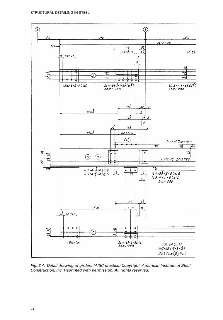
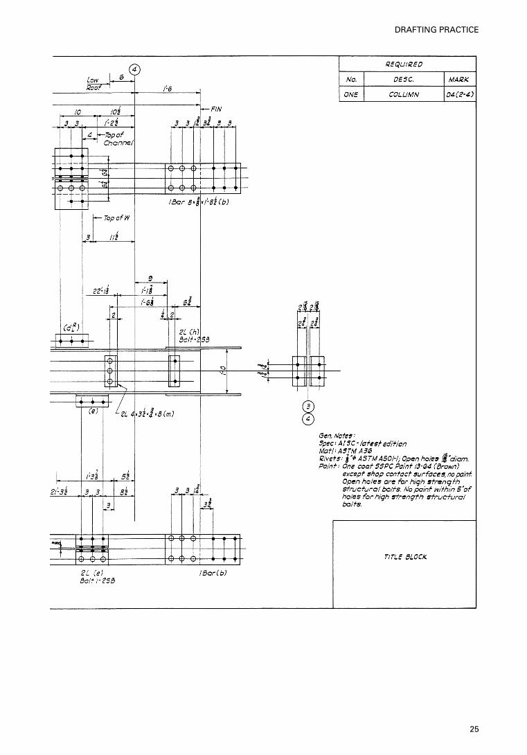
Fig. 3.4. Detail drawing of girders (AISC practice) Copyright: American Institute of SteelConstruction, Inc. Reprinted with permission. All rights reserved.
24
STRUCTURAL DETAILING IN STEEL
25
DRAFTING PRACTICE
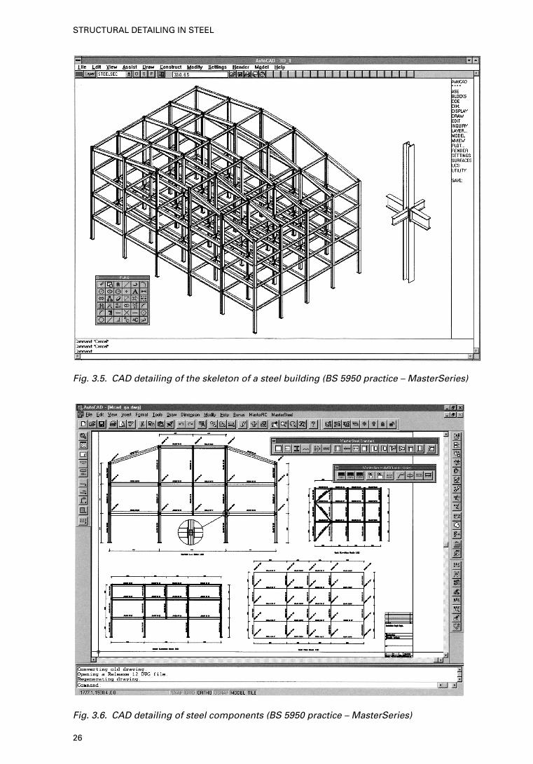
Fig. 3.5. CAD detailing of the skeleton of a steel building (BS 5950 practice – MasterSeries)
Fig. 3.6. CAD detailing of steel components (BS 5950 practice – MasterSeries)
26
STRUCTURAL DETAILING IN STEEL
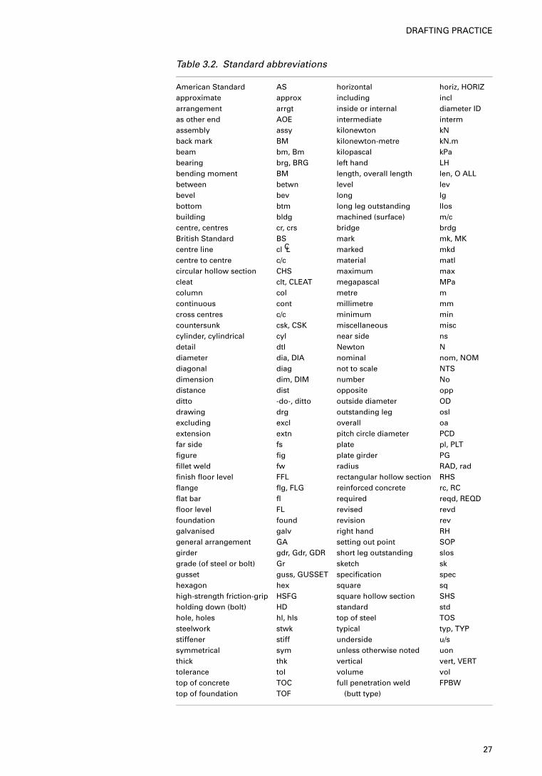
Table 3.2. Standard abbreviations
American Standard AS horizontal horiz, HORIZapproximate approx including inclarrangement arrgt inside or internal diameter IDas other end AOE intermediate intermassembly assy kilonewton kNback mark BM kilonewton-metre kN.mbeam bm, Bm kilopascal kPabearing brg, BRG left hand LHbending moment BM length, overall length len, O ALLbetween betwn level levbevel bev long lgbottom btm long leg outstanding llosbuilding bldg machined (surface) m/ccentre, centres cr, crs bridge brdgBritish Standard BS mark mk, MKcentre line cl CL marked mkdcentre to centre c/c material matlcircular hollow section CHS maximum maxcleat clt, CLEAT megapascal MPacolumn col metre mcontinuous cont millimetre mmcross centres c/c minimum mincountersunk csk, CSK miscellaneous misccylinder, cylindrical cyl near side nsdetail dtl Newton Ndiameter dia, DIA nominal nom, NOMdiagonal diag not to scale NTSdimension dim, DIM number Nodistance dist opposite oppditto -do-, ditto outside diameter ODdrawing drg outstanding leg oslexcluding excl overall oaextension extn pitch circle diameter PCDfar side fs plate pl, PLTfigure fig plate girder PGfillet weld fw radius RAD, radfinish floor level FFL rectangular hollow section RHSflange flg, FLG reinforced concrete rc, RCflat bar fl required reqd, REQDfloor level FL revised revdfoundation found revision revgalvanised galv right hand RHgeneral arrangement GA setting out point SOPgirder gdr, Gdr, GDR short leg outstanding slosgrade (of steel or bolt) Gr sketch skgusset guss, GUSSET specification spechexagon hex square sqhigh-strength friction-grip HSFG square hollow section SHSholding down (bolt) HD standard stdhole, holes hl, hls top of steel TOSsteelwork stwk typical typ, TYPstiffener stiff underside u/ssymmetrical sym unless otherwise noted uonthick thk vertical vert, VERTtolerance tol volume voltop of concrete TOC full penetration weld FPBWtop of foundation TOF (butt type)
27
DRAFTING PRACTICE
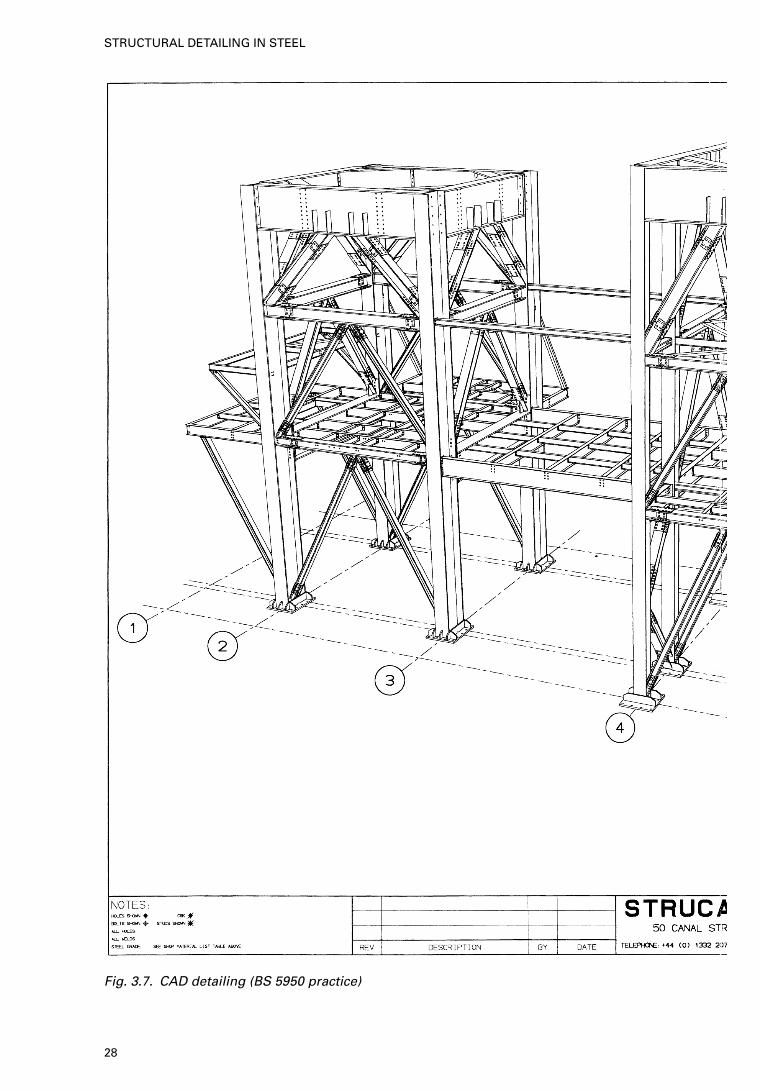
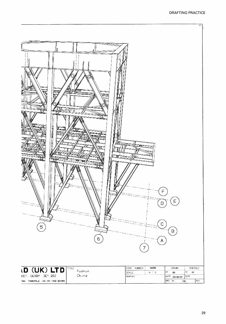
Fig. 3.7. CAD detailing (BS 5950 practice)
28
STRUCTURAL DETAILING IN STEEL
29
DRAFTING PRACTICE
( f ) The code of practice to which the building was designed, so that thedesign of connections and other details can be carried out to the samecode.
( g) The specifications to which the steelwork is to be fabricated, welded anderected.
(h) The grade of steel to be used for the various parts of the building, e.g.Grade Fe 430 (EC3) steel for hot-rolled sections.
(i) The bolt grades to be used for the shop and site connections. Details offriction-grip type connections must be provided by the engineer.
( j) Cambers, if required, for long-span plate girders, lattice girders ortrusses need to be provided.
3.4.4. General
arrangement and
detail drawings
The general arrangement drawings are similar to those provided by theengineer. However, they usually do not include member loads and forces, butdo include member erection marks.
The orientation of the building is shown by means of a north arrow. Wheretrue north is not parallel to one of the sides of the building (in plan), the ‘gridnorth’ convention is used for convenience, this being the direction (parallel toone side) nearest to true north.
Detail drawings depict every individual structure member and componentin the job and include detailed notes on their fabrication. This informationincludes the section size and overall lengths of members, the positions anddiameters of all holes, the positions, types and sizes of all welds, dimensionsof notches, cut-outs and snipes where necessary, details of attachments such ascleats, brackets, base plates, stiffeners, bearing plates, etc., and many otherdetails depending on the type of structure.
30
STRUCTURAL DETAILING IN STEEL
Beams, trusses, purlins, girts and girders are drawn in the horizontalposition, i.e. parallel to the lower edge of the sheet. Short columns are drawnin the vertical position, but long columns are placed horizontally, with theirbases to the right. Inclined girders, such as sloping conveyor gantries, may bedrawn at their true slope or horizontally.
The most commonly used scale for detail drawings is 1:15, but in the caseof more complex members a larger scale, say 1 : 10 would be used.
Detail drawings should be provided with a list of general notes, stating thegrade of steel, the sizes and types of bolts to be used, the diameters of the boltholes and whether the holes should be drilled or punched, the type of weldingelectrodes and what painting is required. Fig. 3.4 gives a layout based on thesesuggestions. Ideally, the drawing should also contain a small scale key plan inone corner showing the location of the detailed item in relation to thestructure. Figs 3.5 to 3.8 show examples of computer aided detailing.
3.4.5. Abbreviations A large number of words and phrases are used repetitively on drawings. Theirsubstitution by abbreviations saves the draughtsman’s time and results in a lesscluttered drawing. It is important, however, that only recognised, standardabbreviations are used and that their use is consistent. A list of the morecommon abbreviations is given in Table 3.2.
31
DRAFTING PRACTICE
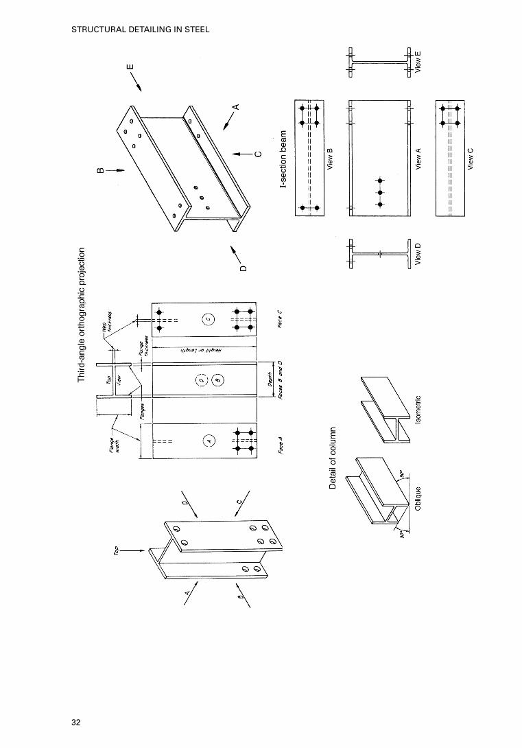
32
STRUCTURAL DETAILING IN STEEL
3.4.6. Orthographic
projection
Although pictorial drawing has some application in developing and commu-nicating ideas, it does not lend itself readily to making structural shopdrawings. As a consequence, a multiview system known as orthographicprojection is used for shop details throughout the industry. The basis of thismethod is to show the characteristics of an object by using as manydimensioned views as necessary to describe it fully.
The objects depicted on a design drawing are three-dimensional or solid,but on paper it is actually only possible to represent them in two dimensions.The method used by artists to create a realistic three-dimensional impressionis called perspective drawing, where the building appears exactly as it wouldin a photograph. A simpler representation is shown in Fig. 3.9, called isometricdrawing, along with a third representation in which three or more views areshown, the viewing axis being normal (perpendicular) to the surface of the partdepicted. Fig. 3.10 indicates beam and column details in third-angleorthographic projection showing various views drawn along A–D directions.
33
DRAFTING PRACTICE
4. Bolts and bolted joints
4.1. Introduction
The most common method of joining one component to another in structuralsteelwork is bolting. Bolting may be carried out either in the shop or on siteand has the advantage that the components can be separated easily should thisbecome necessary for any reason. Most fabricators prefer to use welding forshop connections, but where workshops are equipped with automatedpunching and drilling machines, shop bolting is generally found to be quickerand cheaper. For site connections, however, bolting is virtually the universalmedium of connection. The main function of the bolt is to transmit a forcefrom one member to another.
In all bolted connections a transfer of force is involved and in nearly allcases the transfer is by one or more of the following modes:
(a) shear in the bolt shank,(b) bearing of the bolt shank against the holes in the two components,(c) friction between the parts when the bolt is tightened to clamp the parts
firmly together, and(d ) tension, when the load is applied in the axial direction of the bolt.
All these cases are shown in Fig. 4.1.It is necessary for the steelwork detailer to have a clear understanding of
how bolts work and to be able to select a suitable group of bolts to transmitthe forces specified on the engineer’s drawings.
In the following section, the recommendations given by the British,European and American codes are discussed.
4.2. Types of bolt
Bolts have hexagonal heads and nuts, parallel shanks and threads cut or rolledinto the shanks. They come in standard shank diameters of 12 mm, 16 mm,20 mm and 24 mm in a large range of lengths and in various grades ofstrength. Fig. 4.1 illustrates a typical structural bolt, nut and washer assemblyand gives the associated terminology. Bolts are designated by size, i.e. thenominal diameter of the shank and thread, and by length, i.e. the total lengthof the shank (including thread) up to the underside of the head. The bolt sizesmentioned above are designated M12, M16, M20 and M24 (M meansmetric).
Here the British and the European Codes have common designations. TheAmerican designations are as follows:
• ASTM A307 — Grade A and B (unfinished bolts) 14 in. to 4 in. (6·4 mm to
100 mm)• ASTM A502 — Ribbed type grades• ASTM A325 — Bearing type, same as ASTM A307 for sizes including
16 mm
34
• ASTM A325, A490 — High-strength bolts 5/8 in. to 1 in. (16 mm to25·4 mm)
Table 4.1 gives a summary of the ASTM versions of various bolt types.
4.2.1. ASTM
specifications
A variety of bolt designations exists. Bolts are employed for a number ofdifferent purposes. The following list details some well known designatedbolts.
(a) ASTM A307 (unfinished) bolts — Grade A and Grade B with aminimum tensile strength of 55 ksi for all sizes, 1
4 in. to 4 in. inclusive.They are tightened securely by using long handled manual wrenches andare widely used for relatively light members. The nuts are easilyloosened and hence require special locking features.
(b) Turned bolts (replaced by high-strength bolts).(c) Ribbed bolts — these are interference type fasteners made from carbon
steel �A502 Grade 1 rivet.(d ) Bearing bolts — the bearing bolt incorporates the advantages of the
ribbed bolt and the knurled pattern, and a heavy nut with or without awasher. Bolt ribs are designed with a small taper to facilitate progressthrough the hole. It is claimed that, while driving, the interrupted ribswill not peel, pack under the head or break off; they will cut grooves intothe sides of the hole into the process of filling it. In this manner fullbearing is created along the entire grip length. This body-bound fitaffords not only a fully effective cross-sectional bolt area but also a rigidjoint with an inherent resistance to slippage. Therefore, the bolt willtransmit load primarily by shear and bearing and the initial tensioningnormally required for other high-strength bolts may be consideredunnecessary.
(e) High-strength tension control and tension set bolts — these bolts,commonly known as TC and TS bolts, are similar in performance.Fasteners equivalent to ASTM A325 and A490 bolts in sizes rangingfrom diameters of 5
8 –12 in. can be supplied. Each bolt has a round headwith a torque control notch at its tip. Bolts are installed with an electricwrench which engages both the bolt and the nut in the outer and the innersleeves of the wrench until the notch of the bolt shears off. The bolt doesnot rotate during fastening. The notch is designed to shear off when thefastener is loaded to a predetermined tension. The advantage of thesebolts is that the completion of bolt fastening can be confirmed by theshear-off of the notch, thus eliminating the use of an inspection wrench.Data for various bolts are given in tabulated form, together withindividual specifications beginning with the high-strength bolts.
High-strength boltsHigh-strength bolts produce large and predictable tensions when tightened.Initially, tensioning of high-strength bolts also results in more rigid joints,more satisfactory stress distributions, and greater assurance against nutloosening.
The A325 bolt is available in the following three types:
• Type 1 — bolts of medium-carbon steel, in sizes 12 to 11
2 in. diameter,inclusive
• Type 2 — bolts of low-carbon martensite steel, in sizes 12 to 1 in. diameter,
inclusive (not to be hot galvanised)• Type 3 — bolts having atmospheric corrosion resistance and weathering
characteristics comparable with those of A588 and A242 steels in sizes 12 to11
2 in. diameter, inclusive.
35
BOLTS AND BOLTED JOINTS
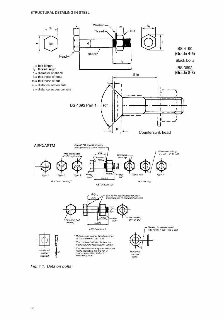
Fig. 4.1. Data on bolts
36
STRUCTURAL DETAILING IN STEEL
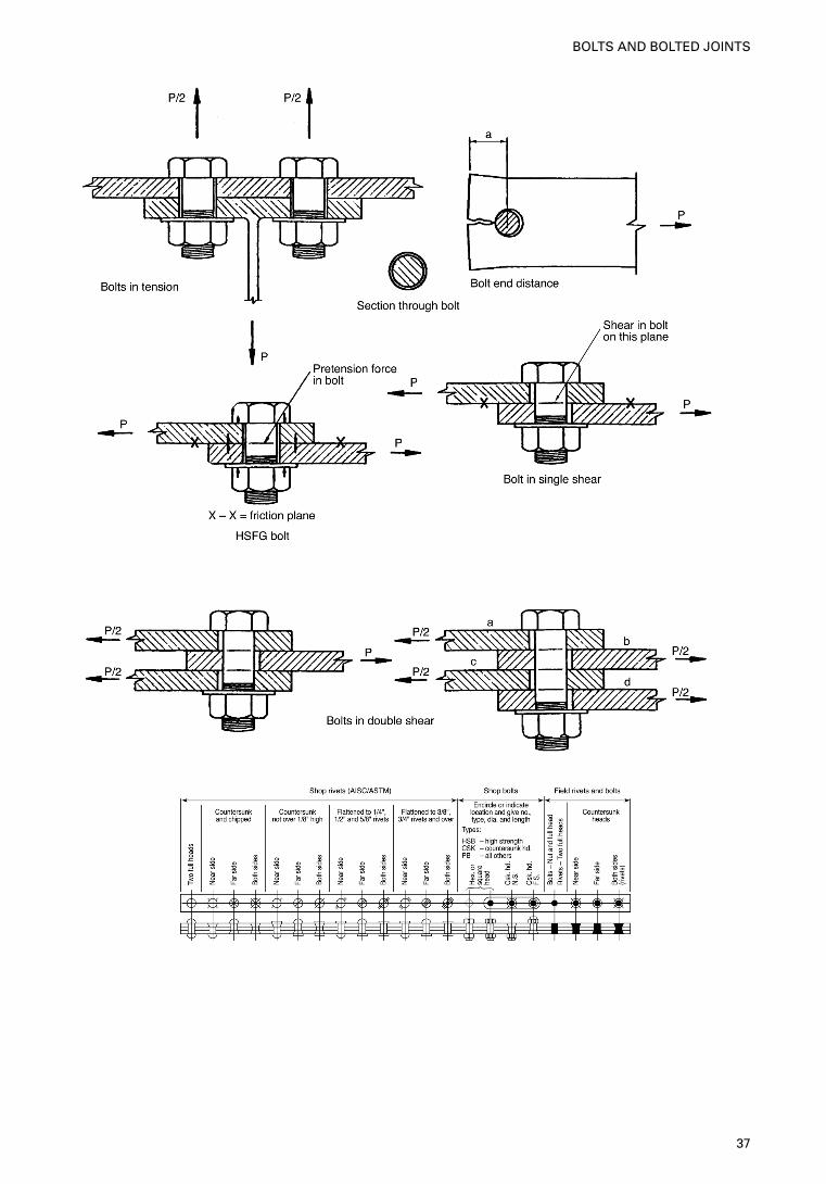
37
BOLTS AND BOLTED JOINTS
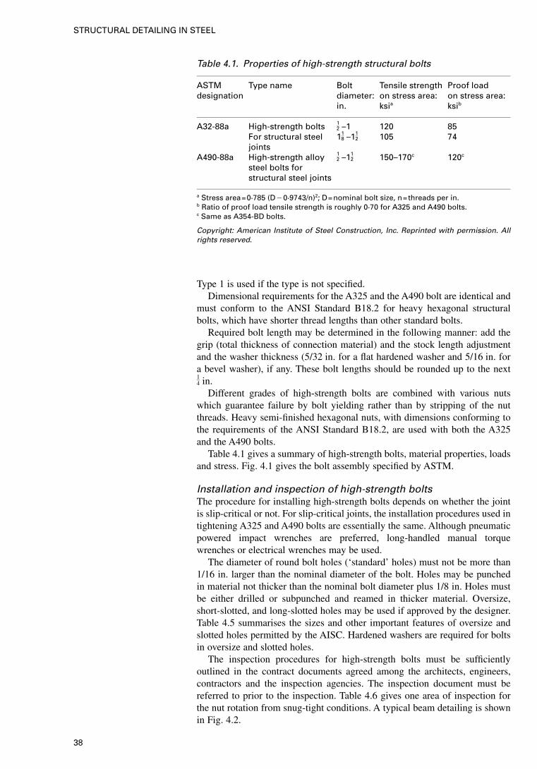
Type 1 is used if the type is not specified.Dimensional requirements for the A325 and the A490 bolt are identical and
must conform to the ANSI Standard B18.2 for heavy hexagonal structuralbolts, which have shorter thread lengths than other standard bolts.
Required bolt length may be determined in the following manner: add thegrip (total thickness of connection material) and the stock length adjustmentand the washer thickness (5/32 in. for a flat hardened washer and 5/16 in. fora bevel washer), if any. These bolt lengths should be rounded up to the next14 in.
Different grades of high-strength bolts are combined with various nutswhich guarantee failure by bolt yielding rather than by stripping of the nutthreads. Heavy semi-finished hexagonal nuts, with dimensions conforming tothe requirements of the ANSI Standard B18.2, are used with both the A325and the A490 bolts.
Table 4.1 gives a summary of high-strength bolts, material properties, loadsand stress. Fig. 4.1 gives the bolt assembly specified by ASTM.
Installation and inspection of high-strength boltsThe procedure for installing high-strength bolts depends on whether the jointis slip-critical or not. For slip-critical joints, the installation procedures used intightening A325 and A490 bolts are essentially the same. Although pneumaticpowered impact wrenches are preferred, long-handled manual torquewrenches or electrical wrenches may be used.
The diameter of round bolt holes (‘standard’ holes) must not be more than1/16 in. larger than the nominal diameter of the bolt. Holes may be punchedin material not thicker than the nominal bolt diameter plus 1/8 in. Holes mustbe either drilled or subpunched and reamed in thicker material. Oversize,short-slotted, and long-slotted holes may be used if approved by the designer.Table 4.5 summarises the sizes and other important features of oversize andslotted holes permitted by the AISC. Hardened washers are required for boltsin oversize and slotted holes.
The inspection procedures for high-strength bolts must be sufficientlyoutlined in the contract documents agreed among the architects, engineers,contractors and the inspection agencies. The inspection document must bereferred to prior to the inspection. Table 4.6 gives one area of inspection forthe nut rotation from snug-tight conditions. A typical beam detailing is shownin Fig. 4.2.
Table 4.1. Properties of high-strength structural bolts
ASTM Type name Bolt Tensile strength Proof loaddesignation diameter: on stress area: on stress area:
in. ksia ksib
A32-88a High-strength bolts 12 –1 120 85
For structural steeljoints
118 –11
2 105 74
A490-88a High-strength alloy 12 –11
2 150–170c 120c
steel bolts forstructural steel joints
a Stress area=0·785 (D�0·9743/n)2; D=nominal bolt size, n=threads per in.b Ratio of proof load tensile strength is roughly 0·70 for A325 and A490 bolts.c Same as A354-BD bolts.
Copyright: American Institute of Steel Construction, Inc. Reprinted with permission. Allrights reserved.
38
STRUCTURAL DETAILING IN STEEL

4.2.2. British and
European codes and
specifications
The three most commonly used types of bolt are the following:
(a) grade 4·8 ordinary bolts — these are used for the great majority ofconnections, especially where force transfer is by shear and bearing,
(b) grade 8·8 precision bolts — having a much higher strength grading andmanufactured to closer dimensional tolerances than ordinary bolts,
(c) high-strength friction-grip bolts — the grade generally used is 8·8S but ahigher grade 10·9S is also available. These bolts are used for forcetransfer by friction between the connected parts.
For other grades refer to Figs 4.3 and 4.4.The strength gradings have the following significance. The first number,
multiplied by 100 is the minimum tensile strength (approximately) of the boltmaterial in MPa. The second number, divided by 10, is the ratio(approximately) of the yield stress or stress at a permanent set of 0·2% to theminimum tensile strength. Therefore, a grade 8·8 bolt has a tensile strength of800 MPa and yield stress of 0·8� 800=640 MPa. A grade 4·8 bolt has a tensilestrength of 420 MPa and yield stress of 340 MPa. The lengths in which eachsize of bolt is available (i.e. the size/length combinations) are given in Table4.8.
Table 4.2. Bolt proof loads
Min. bolt tension: kipsa
Bolt size A325 bolts A490 bolts
12 12 1558 19 2434 28 3578 39 491 51 6411
8 56 8011
4 71 10213
8 85 12111
2 103 148
a Equal to 70% of specified tensile strength.
Copyright: American Institute of Steel Construction, Inc. Reprinted with permission. Allrights reserved.
Table 4.3. Combined tension and shear on bolts
Bolt type Threads in shear plane No threads in shear plane
A325
A490
A307
�(442 �4·39f 2v) �117�1·9 fv �90
147�1·9 fv �113��(442 �4·39f 2
v) �59�1·9 fv �4526�1·8 fv �20�
�(442 �2·15f 2v)
�(542 �1·82f 2v)
�117�1·5 fv �90147�1·5 fv �113�
The AISC-ASD allowable bolt tension in ksi is given by the following: (�FtAb) where,�=0·75; Ft=nominal tension stress. Equations in brackets show AISC-LRFD specification.
Copyright: American Institute of Steel Construction, Inc. Reprinted with permission. Allrights reserved.
39
BOLTS AND BOLTED JOINTS
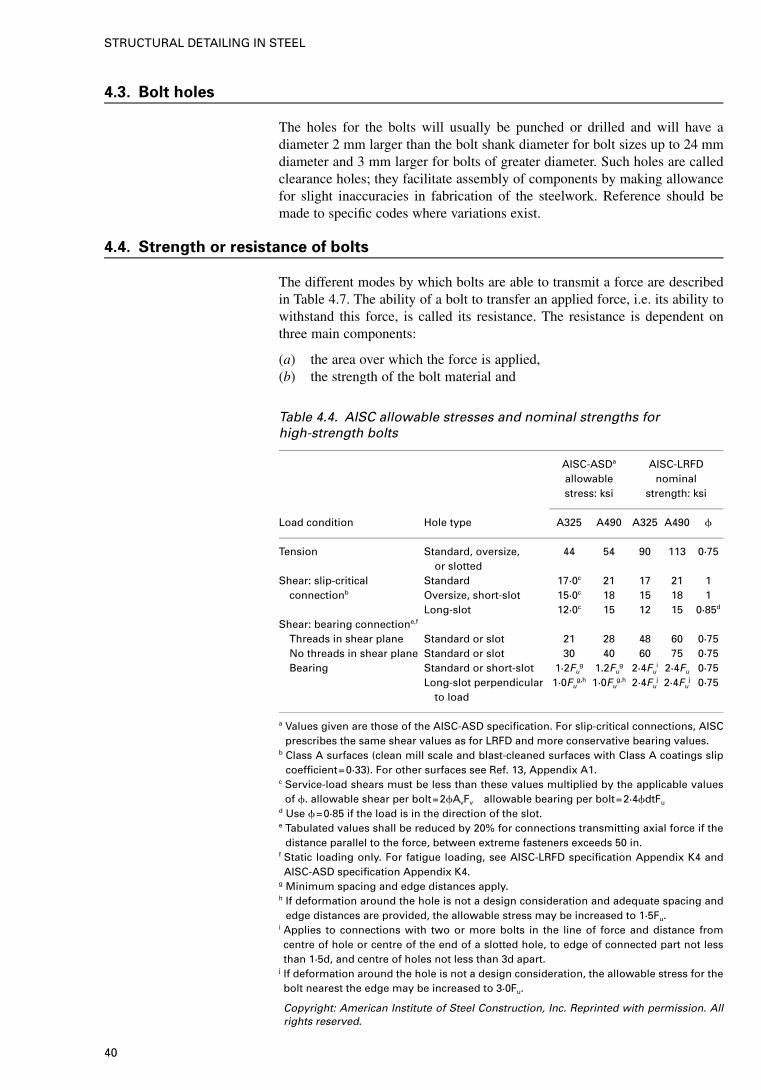
4.3. Bolt holes
The holes for the bolts will usually be punched or drilled and will have adiameter 2 mm larger than the bolt shank diameter for bolt sizes up to 24 mmdiameter and 3 mm larger for bolts of greater diameter. Such holes are calledclearance holes; they facilitate assembly of components by making allowancefor slight inaccuracies in fabrication of the steelwork. Reference should bemade to specific codes where variations exist.
4.4. Strength or resistance of bolts
The different modes by which bolts are able to transmit a force are describedin Table 4.7. The ability of a bolt to transfer an applied force, i.e. its ability towithstand this force, is called its resistance. The resistance is dependent onthree main components:
(a) the area over which the force is applied,(b) the strength of the bolt material and
Table 4.4. AISC allowable stresses and nominal strengths forhigh-strength bolts
AISC-ASDa
allowablestress: ksi
AISC-LRFDnominal
strength: ksi
Load condition Hole type A325 A490 A325 A490 �
Tension Standard, oversize,or slotted
44 54 90 113 0·75
Shear: slip-critical Standard 17·0c 21 17 21 1connectionb Oversize, short-slot 15·0c 18 15 18 1
Long-slot 12·0c 15 12 15 0·85d
Shear: bearing connectione,f
Threads in shear plane Standard or slot 21 28 48 60 0·75No threads in shear plane Standard or slot 30 40 60 75 0·75Bearing Standard or short-slot 1·2Fu
g 1.2Fug 2·4Fu
i 2·4Fu 0·75Long-slot perpendicular
to load1·0Fu
g,h 1·0Fug,h 2·4Fu
j 2·4Fuj 0·75
a Values given are those of the AISC-ASD specification. For slip-critical connections, AISCprescribes the same shear values as for LRFD and more conservative bearing values.
b Class A surfaces (clean mill scale and blast-cleaned surfaces with Class A coatings slipcoefficient=0·33). For other surfaces see Ref. 13, Appendix A1.
c Service-load shears must be less than these values multiplied by the applicable valuesof �. allowable shear per bolt=2�AvFv allowable bearing per bolt=2·4�dtFu
d Use �=0·85 if the load is in the direction of the slot.e Tabulated values shall be reduced by 20% for connections transmitting axial force if the
distance parallel to the force, between extreme fasteners exceeds 50 in.f Static loading only. For fatigue loading, see AISC-LRFD specification Appendix K4 andAISC-ASD specification Appendix K4.
g Minimum spacing and edge distances apply.h If deformation around the hole is not a design consideration and adequate spacing and
edge distances are provided, the allowable stress may be increased to 1·5Fu.i Applies to connections with two or more bolts in the line of force and distance fromcentre of hole or centre of the end of a slotted hole, to edge of connected part not lessthan 1·5d, and centre of holes not less than 3d apart.
j If deformation around the hole is not a design consideration, the allowable stress for thebolt nearest the edge may be increased to 3·0Fu.
Copyright: American Institute of Steel Construction, Inc. Reprinted with permission. Allrights reserved.
40
STRUCTURAL DETAILING IN STEEL
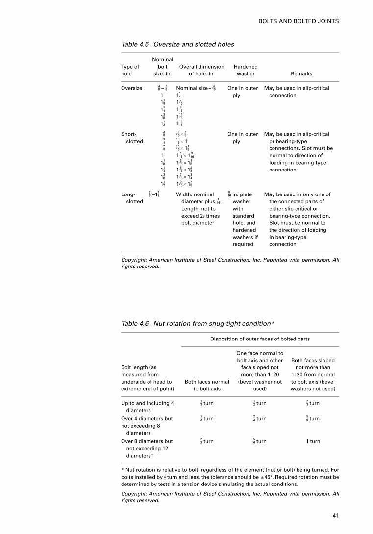
Table 4.5. Oversize and slotted holes
Type ofhole
Nominalbolt
size: in.Overall dimension
of hole: in.Hardened
washer Remarks
Oversize 38 – 7
8
111
8
114
138
112
Nominal size+ 316
114
1 716
1 916
11116
11316
One in outerply
May be used in slip-criticalconnection
Short-slotted
383478
111
8
114
138
112
1116 �
78
1316 �11516 �11
8
1 116 �1 3
16
1 316 �11
8
1 516 �13
8
1 716 �13
4
1 916 �17
8
One in outerply
May be used in slip-criticalor bearing-typeconnections. Slot must benormal to direction ofloading in bearing-typeconnection
Long-slotted
38 –11
2 Width: nominaldiameter plus 1
16.Length: not toexceed 21
2 timesbolt diameter
516 in. plate
washerwithstandardhole, andhardenedwashers ifrequired
May be used in only one ofthe connected parts ofeither slip-critical orbearing-type connection.Slot must be normal tothe direction of loadingin bearing-typeconnection
Copyright: American Institute of Steel Construction, Inc. Reprinted with permission. Allrights reserved.
Table 4.6. Nut rotation from snug-tight condition*
Disposition of outer faces of bolted parts
Bolt length (asmeasured fromunderside of head toextreme end of point)
Both faces normalto bolt axis
One face normal tobolt axis and other
face sloped notmore than 1 :20
(bevel washer notused)
Both faces slopednot more than
1 :20 from normalto bolt axis (bevelwashers not used)
Up to and including 4diameters
13 turn 1
2 turn 23 turn
Over 4 diameters butnot exceeding 8
diameters
12 turn 2
3 turn 56 turn
Over 8 diameters butnot exceeding 12diameters†
23 turn 5
6 turn 1 turn
* Nut rotation is relative to bolt, regardless of the element (nut or bolt) being turned. Forbolts installed by 12 turn and less, the tolerance should be ±45°. Required rotation must bedetermined by tests in a tension device simulating the actual conditions.
Copyright: American Institute of Steel Construction, Inc. Reprinted with permission. Allrights reserved.
41
BOLTS AND BOLTED JOINTS
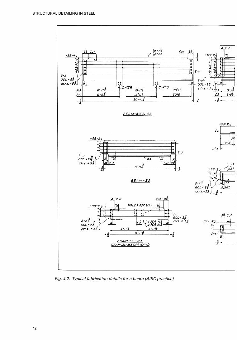
Fig. 4.2. Typical fabrication details for a beam (AISC practice)
42
STRUCTURAL DETAILING IN STEEL
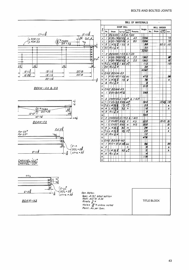
43
BOLTS AND BOLTED JOINTS
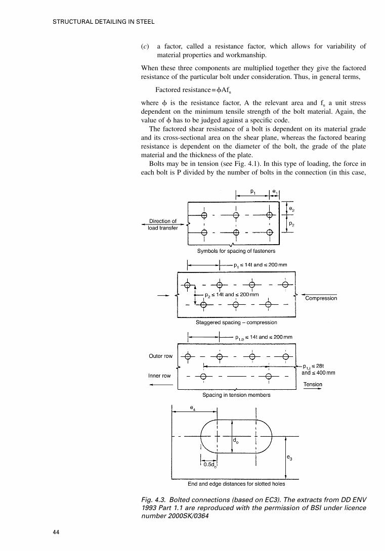
(c) a factor, called a resistance factor, which allows for variability ofmaterial properties and workmanship.
When these three components are multiplied together they give the factoredresistance of the particular bolt under consideration. Thus, in general terms,
Factored resistance=�Afu
where � is the resistance factor, A the relevant area and fu a unit stressdependent on the minimum tensile strength of the bolt material. Again, thevalue of � has to be judged against a specific code.
The factored shear resistance of a bolt is dependent on its material gradeand its cross-sectional area on the shear plane, whereas the factored bearingresistance is dependent on the diameter of the bolt, the grade of the platematerial and the thickness of the plate.
Bolts may be in tension (see Fig. 4.1). In this type of loading, the force ineach bolt is P divided by the number of bolts in the connection (in this case,
Fig. 4.3. Bolted connections (based on EC3). The extracts from DD ENV1993 Part 1.1 are reproduced with the permission of BSI under licencenumber 2000SK/0364
44
STRUCTURAL DETAILING IN STEEL
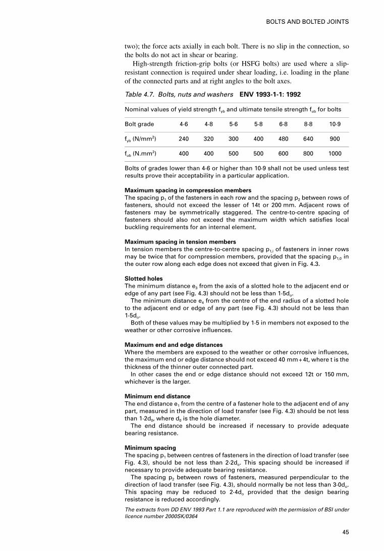
two); the force acts axially in each bolt. There is no slip in the connection, sothe bolts do not act in shear or bearing.
High-strength friction-grip bolts (or HSFG bolts) are used where a slip-resistant connection is required under shear loading, i.e. loading in the planeof the connected parts and at right angles to the bolt axes.
Table 4.7. Bolts, nuts and washers ENV 1993-1-1: 1992
Nominal values of yield strength fyb and ultimate tensile strength fub for bolts
Bolt grade 4·6 4·8 5·6 5·8 6·8 8·8 10·9
fyb (N/mm2) 240 320 300 400 480 640 900
fub (N.mm2) 400 400 500 500 600 800 1000
Bolts of grades lower than 4·6 or higher than 10·9 shall not be used unless testresults prove their acceptability in a particular application.
Maximum spacing in compression members
The spacing p1 of the fasteners in each row and the spacing p2 between rows offasteners, should not exceed the lesser of 14t or 200 mm. Adjacent rows offasteners may be symmetrically staggered. The centre-to-centre spacing offasteners should also not exceed the maximum width which satisfies localbuckling requirements for an internal element.
Maximum spacing in tension members
In tension members the centre-to-centre spacing p1,i of fasteners in inner rowsmay be twice that for compression members, provided that the spacing p1,0 inthe outer row along each edge does not exceed that given in Fig. 4.3.
Slotted holes
The minimum distance e3 from the axis of a slotted hole to the adjacent end oredge of any part (see Fig. 4.3) should not be less than 1·5do.
The minimum distance e4 from the centre of the end radius of a slotted holeto the adjacent end or edge of any part (see Fig. 4.3) should not be less than1·5do.
Both of these values may be multiplied by 1·5 in members not exposed to theweather or other corrosive influences.
Maximum end and edge distances
Where the members are exposed to the weather or other corrosive influences,the maximum end or edge distance should not exceed 40 mm+4t, where t is thethickness of the thinner outer connected part.
In other cases the end or edge distance should not exceed 12t or 150 mm,whichever is the larger.
Minimum end distance
The end distance e1 from the centre of a fastener hole to the adjacent end of anypart, measured in the direction of load transfer (see Fig. 4.3) should be not lessthan 1·2d0, where d0 is the hole diameter.
The end distance should be increased if necessary to provide adequatebearing resistance.
Minimum spacing
The spacing p1 between centres of fasteners in the direction of load transfer (seeFig. 4.3), should be not less than 2·2do. This spacing should be increased ifnecessary to provide adequate bearing resistance.
The spacing p2 between rows of fasteners, measured perpendicular to thedirection of laod transfer (see Fig. 4.3), should normally be not less than 3·0do.This spacing may be reduced to 2·4do provided that the design bearingresistance is reduced accordingly.
The extracts from DD ENV 1993 Part 1.1 are reproduced with the permission of BSI underlicence number 2000SK/0364
45
BOLTS AND BOLTED JOINTS
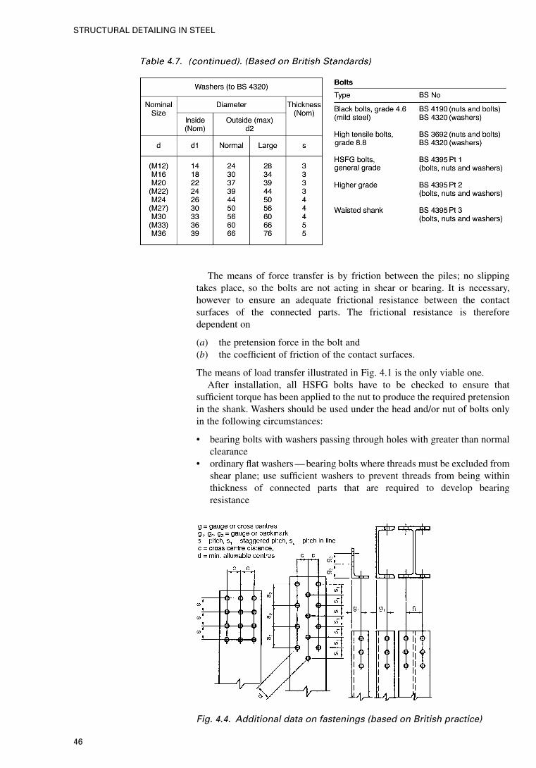
The means of force transfer is by friction between the piles; no slippingtakes place, so the bolts are not acting in shear or bearing. It is necessary,however to ensure an adequate frictional resistance between the contactsurfaces of the connected parts. The frictional resistance is thereforedependent on
(a) the pretension force in the bolt and(b) the coefficient of friction of the contact surfaces.
The means of load transfer illustrated in Fig. 4.1 is the only viable one.After installation, all HSFG bolts have to be checked to ensure that
sufficient torque has been applied to the nut to produce the required pretensionin the shank. Washers should be used under the head and/or nut of bolts onlyin the following circumstances:
• bearing bolts with washers passing through holes with greater than normalclearance
• ordinary flat washers — bearing bolts where threads must be excluded fromshear plane; use sufficient washers to prevent threads from being withinthickness of connected parts that are required to develop bearingresistance
Fig. 4.4. Additional data on fastenings (based on British practice)
46
STRUCTURAL DETAILING IN STEEL
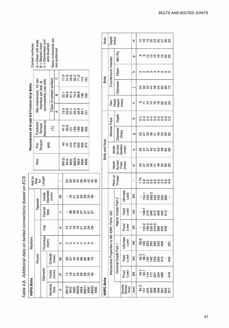
47
BOLTS AND BOLTED JOINTS
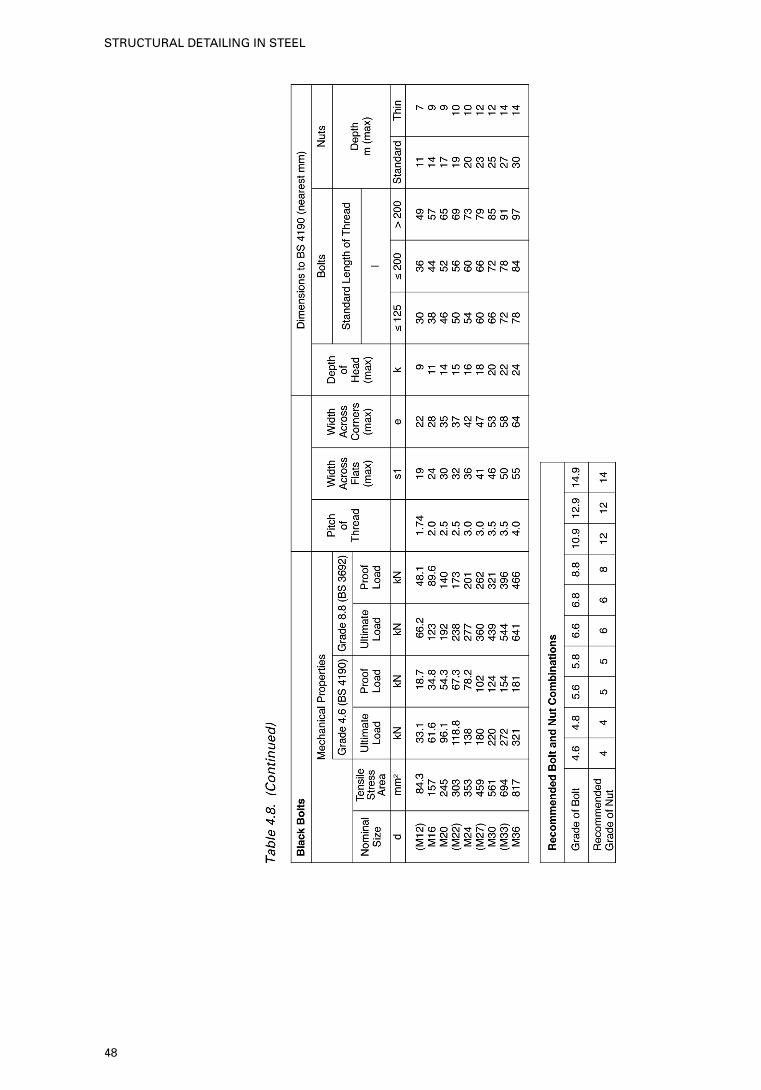
48
STRUCTURAL DETAILING IN STEEL
• ordinary flat washers — HSFG bolts where the torque-control method oftightening is used
• flat through-hardened washers — bolts passing through tapered flanges ofI-sections or channels, or other tapered elements.
4.5. Layout of bolts
The arrangement of the bolt holes usually follows a rectangular pattern, i.e. theholes are in rows and the holes in one row are opposite those in other rows,as shown in Fig. 4.3. This provides for easier setting out and a neatappearance. The spacing between bolts in the longitudinal direction ofmember is called pitch and the spacing at right angles to this is called cross-centre distance. The minimum pitches and cross-centres that are allowablefrom a design point of view are laid down in various codes. When the bolts inalternate rows are offset from those in intermediate rows they are said to be instaggered pattern (see Fig. 4.3). This pattern is used when a large number ofbolts are to be fitted into a limited width, since the zig-zag arrangement allowsthe bolts to be more closely nestled while still maintaining the requiredminimum centre-to-centre distance, d. However, the length of the bolt groupis increased.
Holes in the flanges of I- and H-sections and channels and the legs of anglesare usually placed on lines at a set distance from the web centres of the I- andH-sections (gauge lines or cross-centre lines) or from the backs of channels orangles.
4.5.1. ENV 1993-1-1:
1992 (EC3)
requirements
Figure 4.4 gives specifications for bolts and other parameters for bolts inspecial circumstances including spacings and edge distances. The clearancesin standard holes for fasteners (except for fitted bolts) are given by EC3 asfollows:
• 1 mm for M12 and M14 bolts• 2 mm for M16 and M24 bolts• 3 mm for M27 and larger bolts
Holes with smaller clearances than standard holes may be specified. Holeswith 2 mm nominal clearance may also be specified for M12 and M14 bolts,provided that the design meets the requirements. Oversize and slotted holesmay be used for slip-resistance connections only where specified. The nominalclearance in oversize holes for slip-resistant connections shall be:
• 3 mm for M12 bolts• 4 mm for M14 to M22 bolts• 6 mm for M24 bolts• 8 mm for M27 and larger bolts.
Oversize holes in the outer ply of a slip-resistant connection shall be coveredby hardened washers. Holes for holding down bolts may be oversize holeswith clearance as specified in the project specification, provided that theseholes are covered by cover plates of appropriate dimensions and thickness.The holes in the cover plates shall not be larger than standard. The nominalsizes of short slotted holes for slip resistant connections shall be not greaterthan:
• (d+1) mm by (d+4) mm for M12 and M14 bolts• (d+2) mm by (d+6) mm for M16 to M22 bolts• (d+2) mm by (d+8) mm for M24 bolts• (d+3) mm by (d+10) mm for M27 and larger bolts
49
BOLTS AND BOLTED JOINTS
where d is the nominal bolt diameter in mm.The nominal sizes of long slotted holes for slip-resistant connections shall
be not greater than:
• (d+1) mm by 2·5d for M12 and M14 bolts• (d+1) mm by 2·5d for M16 and M24 bolts• (d+1) mm by 2·5d for M27 and larger bolts
Slots in an outer ply shall be covered by cover plates of appropriatedimensions and thickness. The holes in the cover plates shall not be longerthan standard holes. The sizes required for long slotted holes for movementjoints shall be specified.
BoltsWhere design is based on bolts with unthreaded shanks in the shear plane,appropriate measures shall be specified to ensure that, after allowing fortolerances, neither the threads nor the thread run-out will be in the shearplane.
Bolts with threads up to the head may be used except where prohibited bythe project specification. The length of non-preloaded bolts shall be such that,after allowing for tolerances:
• the threaded shank will protrude beyond the nut after tightening, and• at least one full thread (in addition to the thread run-out) will remain clear
between the nut and the unthreaded part of the shank.
The length of a preloaded bolt shall be such that, after allowing fortolerances:
• the threaded shank will protrude beyond the nut after tightening, and• at least four full threads (in addition to the thread run-out) will remain clear
between the nut and the unthreaded part of the shank.
NutsFor structures subject to vibration, measures shall be taken to avoid anyloosening of the nuts. If non-preloaded bolts are used in structures subject tovibrations, the nuts should be secured by locking devices or other mechanicalmeans. The nuts of preloaded bolts may be assumed to be sufficiently securedby the normal tightening procedure. Steel packing plates shall be providedwhere necessary to ensure that the remaining step does not exceed thespecified limit. Unless a greater value is specified, the minimum thickness ofa steel packing plate should be:
• 2 mm in indoor conditions, if exposed to corrosive influences• 4 mm in outdoor conditions or if exposed to corrosive influences.
50
STRUCTURAL DETAILING IN STEEL
5. Welding
5.1. Introduction
Welding is the fusing together of two pieces of steel by means of heat to forma single piece. The heat is produced by the passage of an electric currentthrough an electrode, causing the surfaces of the two pieces and the metalfrom the electrode to melt and fuse into one on cooling.
There are two main types of weld: butt welds and fillet welds. A butt weld(or groove weld) is defined as one in which the metal lies substantially withinthe planes of the surfaces of the joined components. A full penetration buttweld is normally expected to develop full strength. A partial penetration weldachieves a specified depth of penetration only. The most commonly usedwelding processes are manual metal arc welding (as described below),automatic welding with a continuous coated electrode feeding automaticallyoff a drum, gas shielded welding, where a bare electrode is used, andsubmerged arc welding, which utilises an arc entirely submerged in a granularflux that is fed progressively onto the molten weld pool as welding proceeds.A fillet weld is approximately triangular in section, formed within a reentrantcorner of a joint. Its strength is achieved through shear capacity of the weldmetal across the throat, the weld size being specified as the leg length.
The results of a comparative study of the three main codes AISC (AmericanInstitute of Steel Construction), British and European, are given below.Differences in the methodology and specifications have been highlighted,supported by self-explanatory diagrams and tables.
5.2. Welded connections, joints and weld types
There are some 40 jointing processes, which may be categorised into 9 majorgroups: brazing, flow, forge, induction, thermit, gas, resistance electroslag,electrogas and arc welding. Arc welding can be more precisely categorised asshielded metal-arc welding (‘stick’ welding) flux-cored arc welding andsubmerged arc welding. Welds may be classified in terms of the position of theweld during welding, the type of weld, type of joint or the magnitude and typeof forces to be transmitted. Only a combination of these categories will definea weldment adequately. It is necessary to understand the difference betweenthe terms ‘joint types’ and ‘weld types’. ‘Joint types’ describes theconfiguration of the steel parts relative to each other, while ‘weld types’ refersto the type of weld employed to hold the parts together. Fig. 5.1 depicts somebasic types of joint used in structural engineering in the USA. Fig. 5.2 givesthe recommendations made by Eurocode 3. Almost all the welds used to makethe above joints are of two basic types: groove welds and fillet welds. Groovewelds can be subdivided into square, bevel, V, J and U types depending on theshape to which the plate edge is prepared or grooved to accommodate theweld.
5.2.1. Reinforcement
and backing
Where a complete joint penetration weld is required and the weld has a singlebevel, V or U groove, the small weld opposite the main weld may be laid-
51
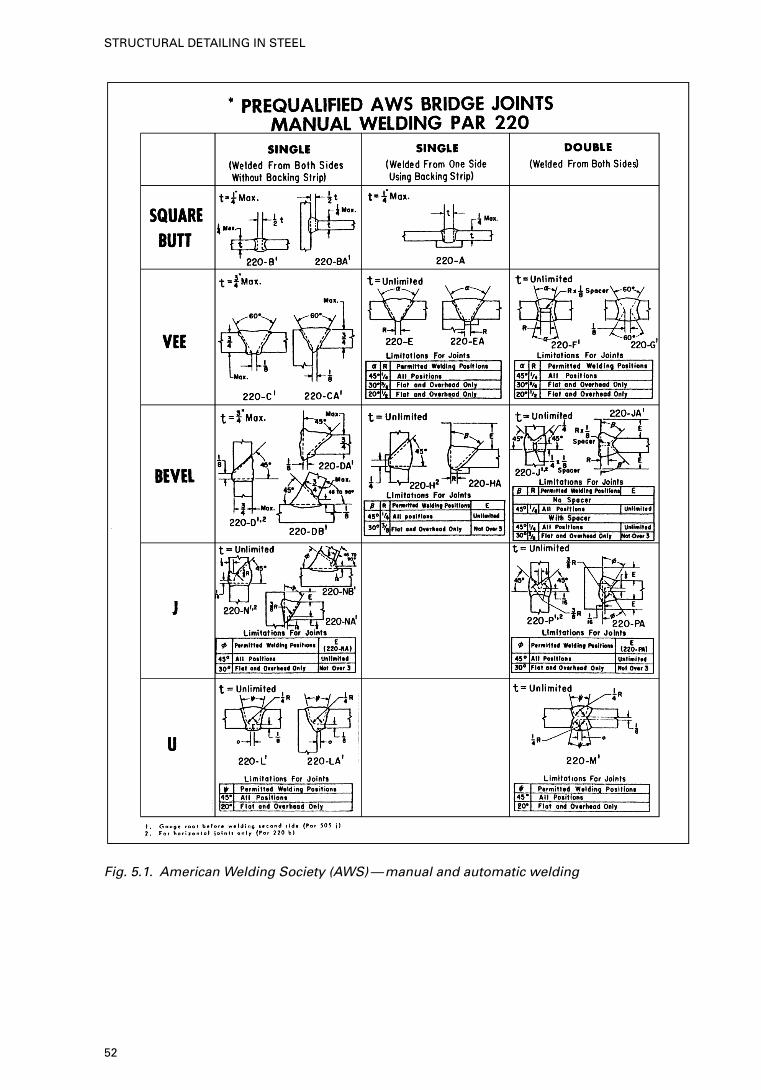
Fig. 5.1. American Welding Society (AWS)—manual and automatic welding
52
STRUCTURAL DETAILING IN STEEL
either before or after the main weld; in the former case the small weld is calleda backing weld and in the latter a back weld.
When access is available on only one side of a joint but full jointpenetration is required, a steel backing strip may be used. The bar is tack-welded to one or both of the plates and when the first run of the main weld islaid it fuses onto the strip to provide full penetration.
5.2.2. Welding
positions
The term ‘position’ when used in connection with a welded joint refers to theposition in which the bead is laid, i.e. whether flat, horizontal, vertical,overhead, etc. The welding position is of great importance since the quality ofthe weld is directly affected by the manner in which the weld metal isdeposited. Not all electrodes are suitable for all positions; many electrodes arespecified for use in a particular position and should be used only in thatposition to obtain good results.
5.2.3. Distortion Once a molten weld bead has been deposited and begins to cool, it willsolidify and attempt to contract, both along and across its axis. This willinduce residual tensile stresses because of the restraint imposed by thesurrounding structure, as well as distortions due to the lack of completerigidity in the surrounding structure.
Longitudinal shrinkage of a built-up welded member can cause slenderwebs and outstands to buckle and if the weld or welds are eccentric to thecentroid of the member cross-section will cause overall bowing of themember. Transverse shrinkage is likely to cause both angular and out-of-planedistortions.
5.2.4. Electrodes Each combination of weldable steel, welding condition and welding positionrequires the use of specific electrodes, classified on the basis of the mechanicalproperties of the deposited weld metal, the welding position of the electrode,the type of coating or covering and the type of current required. Each electrodeis identified by a code number EXXXXX, where E stands for electrode andeach X represents a number. The first two (or three) numbers indicate theminimum tensile strength, in ksi, of the deposited metal in the as-weldedcondition. The next number refers to the position in which the electrode iscapable of making satisfactory welds; 1 means all positions (flat, vertical,overhead and horizontal), 2 means flat and horizontal fillet welds, and 3 meansflat only. The last X represents a digit which indicates the current to be usedand the type of coating or covering on the electrode, e.g. (1) high-cellulosesodium coating for use with direct-current reverse polarity (electrode positive)only; or (2) iron powder/titania coating for use with direct current, eitherpolarity or alternating current. Hence, E6018 implies a mild-steel arc-weldingelectrode with a minimum tensile strength of 60 ksi. Similar values are givenin SI units.
Electrodes for shielded metal-arc welding are manufactured in sizesranging in diameter from 1/16 to 3/8 in. and in length from 9 to 18 in. Coatingsserve as mediums for incorporating alloying elements which affect the tensilestrength, hardness, corrosion resistance and other physical properties of theweld metal.
In submerged-arc welding, appropriate combinations of bare electrodes andgranular fusible fluxes are selected to produce the specified properties in thedeposited weld metal. Choices are governed by the welding procedure, thetype of joint and the composition of the base metal. The designations areGrade SAW-1 and Grade SAW-2 which imply weld metal yield points of 45and 50 ksi respectively.
53
WELDING
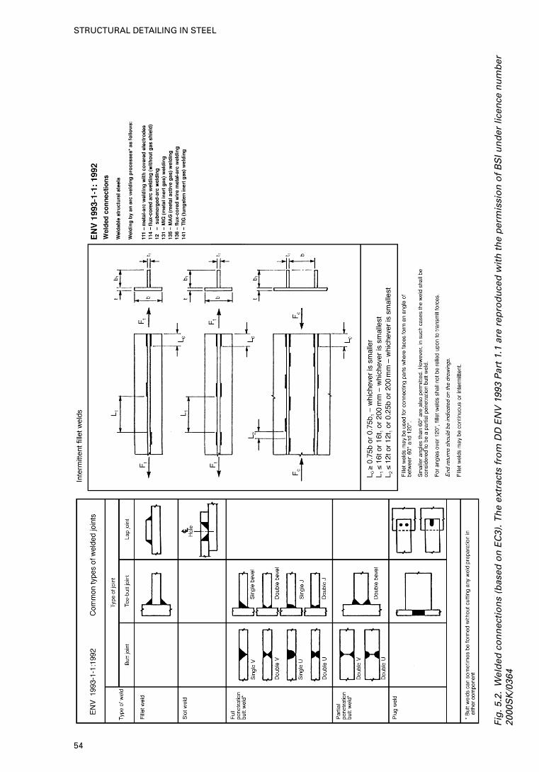
Fig
.5.2
.W
eld
ed c
on
nec
tio
ns
(bas
ed o
n E
C3)
. Th
e ex
trac
ts f
rom
DD
EN
V 1
993
Par
t 1.
1 ar
e re
pro
du
ced
wit
h t
he
per
mis
sio
n o
f B
SI u
nd
er li
cen
ce n
um
ber
2000
SK
/036
4
54
STRUCTURAL DETAILING IN STEEL
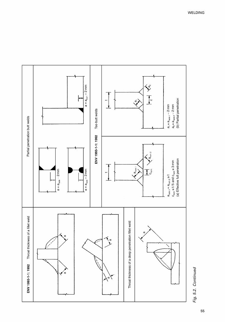
Fig
.5.2
.C
on
tin
ued
55
WELDING
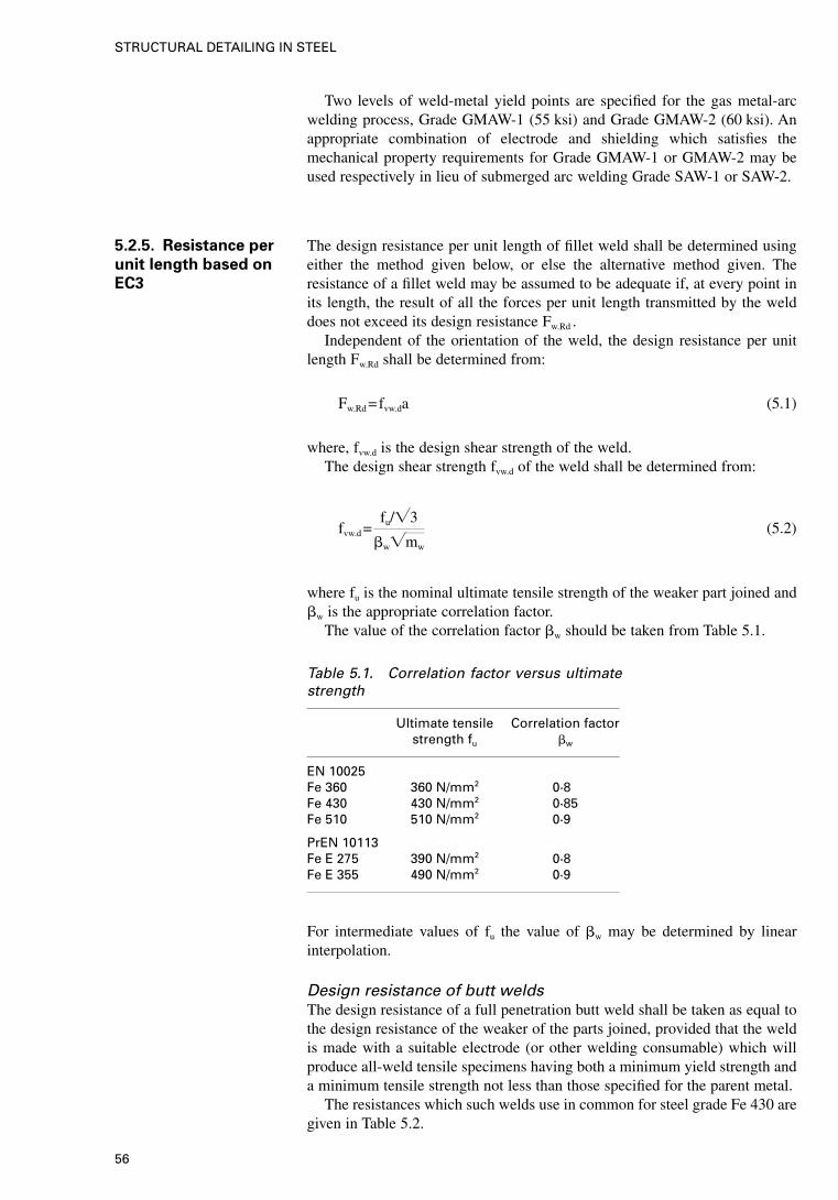
Two levels of weld-metal yield points are specified for the gas metal-arcwelding process, Grade GMAW-1 (55 ksi) and Grade GMAW-2 (60 ksi). Anappropriate combination of electrode and shielding which satisfies themechanical property requirements for Grade GMAW-1 or GMAW-2 may beused respectively in lieu of submerged arc welding Grade SAW-1 or SAW-2.
5.2.5. Resistance per
unit length based on
EC3
The design resistance per unit length of fillet weld shall be determined usingeither the method given below, or else the alternative method given. Theresistance of a fillet weld may be assumed to be adequate if, at every point inits length, the result of all the forces per unit length transmitted by the welddoes not exceed its design resistance Fw.Rd .
Independent of the orientation of the weld, the design resistance per unitlength Fw.Rd shall be determined from:
Fw.Rd =fvw.da (5.1)
where, fvw.d is the design shear strength of the weld.The design shear strength fvw.d of the weld shall be determined from:
fvw.d =fu/�3
�w�mw
(5.2)
where fu is the nominal ultimate tensile strength of the weaker part joined and�w is the appropriate correlation factor.
The value of the correlation factor �w should be taken from Table 5.1.
Table 5.1. Correlation factor versus ultimatestrength
Ultimate tensile Correlation factorstrength fu �w
EN 10025Fe 360 360 N/mm2 0·8Fe 430 430 N/mm2 0·85Fe 510 510 N/mm2 0·9
PrEN 10113Fe E 275 390 N/mm2 0·8Fe E 355 490 N/mm2 0·9
For intermediate values of fu the value of �w may be determined by linearinterpolation.
Design resistance of butt weldsThe design resistance of a full penetration butt weld shall be taken as equal tothe design resistance of the weaker of the parts joined, provided that the weldis made with a suitable electrode (or other welding consumable) which willproduce all-weld tensile specimens having both a minimum yield strength anda minimum tensile strength not less than those specified for the parent metal.
The resistances which such welds use in common for steel grade Fe 430 aregiven in Table 5.2.
56
STRUCTURAL DETAILING IN STEEL
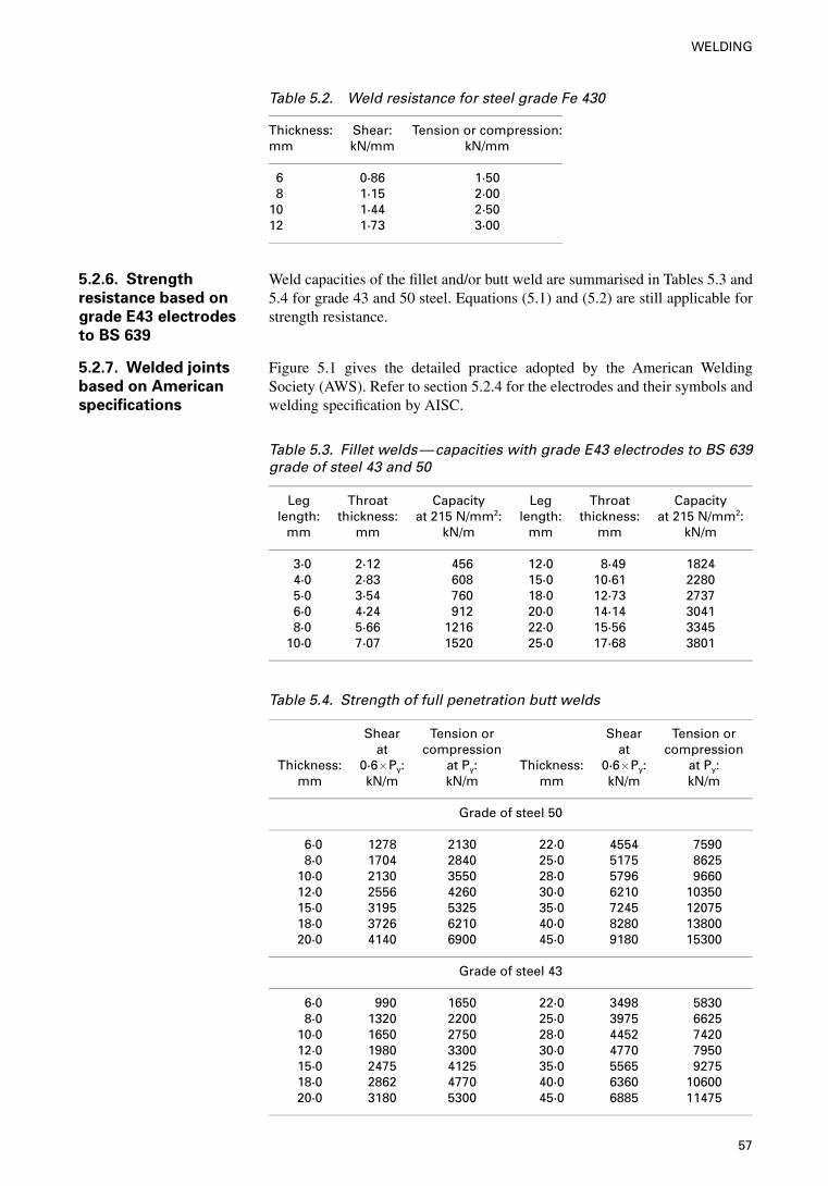
Table 5.2. Weld resistance for steel grade Fe 430
Thickness:mm
Shear:kN/mm
Tension or compression:kN/mm
6 0·86 1·508 1·15 2·00
10 1·44 2·5012 1·73 3·00
5.2.6. Strength
resistance based on
grade E43 electrodes
to BS 639
Weld capacities of the fillet and/or butt weld are summarised in Tables 5.3 and5.4 for grade 43 and 50 steel. Equations (5.1) and (5.2) are still applicable forstrength resistance.
5.2.7. Welded joints
based on American
specifications
Figure 5.1 gives the detailed practice adopted by the American WeldingSociety (AWS). Refer to section 5.2.4 for the electrodes and their symbols andwelding specification by AISC.
Table 5.3. Fillet welds—capacities with grade E43 electrodes to BS 639grade of steel 43 and 50
Leg Throat Capacity Leg Throat Capacitylength: thickness: at 215 N/mm2: length: thickness: at 215 N/mm2:
mm mm kN/m mm mm kN/m
3·0 2·12 456 12·0 8·49 18244·0 2·83 608 15·0 10·61 22805·0 3·54 760 18·0 12·73 27376·0 4·24 912 20·0 14·14 30418·0 5·66 1216 22·0 15·56 3345
10·0 7·07 1520 25·0 17·68 3801
Table 5.4. Strength of full penetration butt welds
Shear Tension or Shear Tension orat compression at compression
Thickness: 0·6�Py: at Py: Thickness: 0·6�Py: at Py:mm kN/m kN/m mm kN/m kN/m
Grade of steel 50
6·0 1278 2130 22·0 4554 75908·0 1704 2840 25·0 5175 8625
10·0 2130 3550 28·0 5796 966012·0 2556 4260 30·0 6210 1035015·0 3195 5325 35·0 7245 1207518·0 3726 6210 40·0 8280 1380020·0 4140 6900 45·0 9180 15300
Grade of steel 43
6·0 990 1650 22·0 3498 58308·0 1320 2200 25·0 3975 6625
10·0 1650 2750 28·0 4452 742012·0 1980 3300 30·0 4770 795015·0 2475 4125 35·0 5565 927518·0 2862 4770 40·0 6360 1060020·0 3180 5300 45·0 6885 11475
57
WELDING
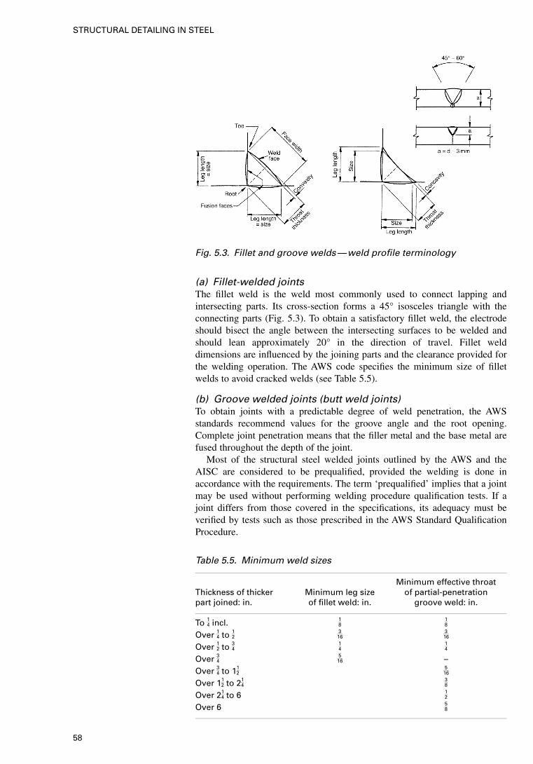
(a) Fillet-welded jointsThe fillet weld is the weld most commonly used to connect lapping andintersecting parts. Its cross-section forms a 45° isosceles triangle with theconnecting parts (Fig. 5.3). To obtain a satisfactory fillet weld, the electrodeshould bisect the angle between the intersecting surfaces to be welded andshould lean approximately 20° in the direction of travel. Fillet welddimensions are influenced by the joining parts and the clearance provided forthe welding operation. The AWS code specifies the minimum size of filletwelds to avoid cracked welds (see Table 5.5).
(b) Groove welded joints (butt weld joints)To obtain joints with a predictable degree of weld penetration, the AWSstandards recommend values for the groove angle and the root opening.Complete joint penetration means that the filler metal and the base metal arefused throughout the depth of the joint.
Most of the structural steel welded joints outlined by the AWS and theAISC are considered to be prequalified, provided the welding is done inaccordance with the requirements. The term ‘prequalified’ implies that a jointmay be used without performing welding procedure qualification tests. If ajoint differs from those covered in the specifications, its adequacy must beverified by tests such as those prescribed in the AWS Standard QualificationProcedure.
Fig. 5.3. Fillet and groove welds—weld profile terminology
Table 5.5. Minimum weld sizes
Minimum effective throatThickness of thicker Minimum leg size of partial-penetrationpart joined: in. of fillet weld: in. groove weld: in.
To 14 incl. 18
18
Over 14 to 12316
316
Over 12 to 3414
14
Over 34516 –
Over 34 to 112
516
Over 112 to 21
438
Over 214 to 6 1
2
Over 6 58
58
STRUCTURAL DETAILING IN STEEL
The system of groove weld classification is not to be confused with theideographic weld identification system adopted by the AWS which uses thefollowing notation.
(1) Joint type: B=butt, C=corner, T=tee(2) Material thickness and efficiency:
L=limited thickness with complete penetrationU=unlimited thickness with complete penetrationP=partial penetration
(3) Groove type:1 — square 4 — single-bevel 7 — double-U2 — single-V 5 — double-bevel 8 — single-J3 — double-V 6 — single-U 9 — double-J
(4) Welding process:S=submerged arcNo symbol indicates manual shielded metal arc.
For example, the designation TC – U4 means (1) the joint may be used foreither a tee or a corner, (2) it may be used on an unlimited range of materialthicknesses, (3) the groove is a single-bevel, and (4) the welding will beperformed by the manual shielded metal arc process.
The groove welded strength is given in Table 5.4.
5.3. Welding symbols
Standardised symbols are used to denote the type and size of welds onstructural detail drawings. The following points should be noted in connectionwith the construction and use of welding symbols.
(a) The reference line is drawn in either the horizontal or the verticaldirection, i.e. parallel to the horizontal or vertical axis of drawing. Ifplaced vertically, the information on it should be able to be read whenthe drawing is viewed from the right.
(b) The arrow points to the weld(s) or welded joint being described.(c) The fillet weld symbol is a small isosceles triangle based on the
reference line and having its vertical side to the left.(d ) The single-bevel weld symbol is a 45° V with its apex to the reference
line and its vertical leg to the left.(e) The double-bevel and double-V weld symbols have their legs at 60° to
each other.( f ) Symbols and notations referring to the arrow side of the joint are placed
below the reference line; those referring to the other side of the joint areplaced above it.
Figure 5.4 shows a summary of standard welding symbols recommended bythe American Welding Society (AWS) which have been universally adopted.For clarity, the application of these symbols is explained by a series oftabulated examples in Fig. 5.4. These have been used in the UK and countriescovered by the Eurocodes.
5.4. Practical notes for guidance
Figure 5.5 summarises practical guidance for detailers prior to the preparationof GA drawings and structural details for welded steel structures. Where
59
WELDING
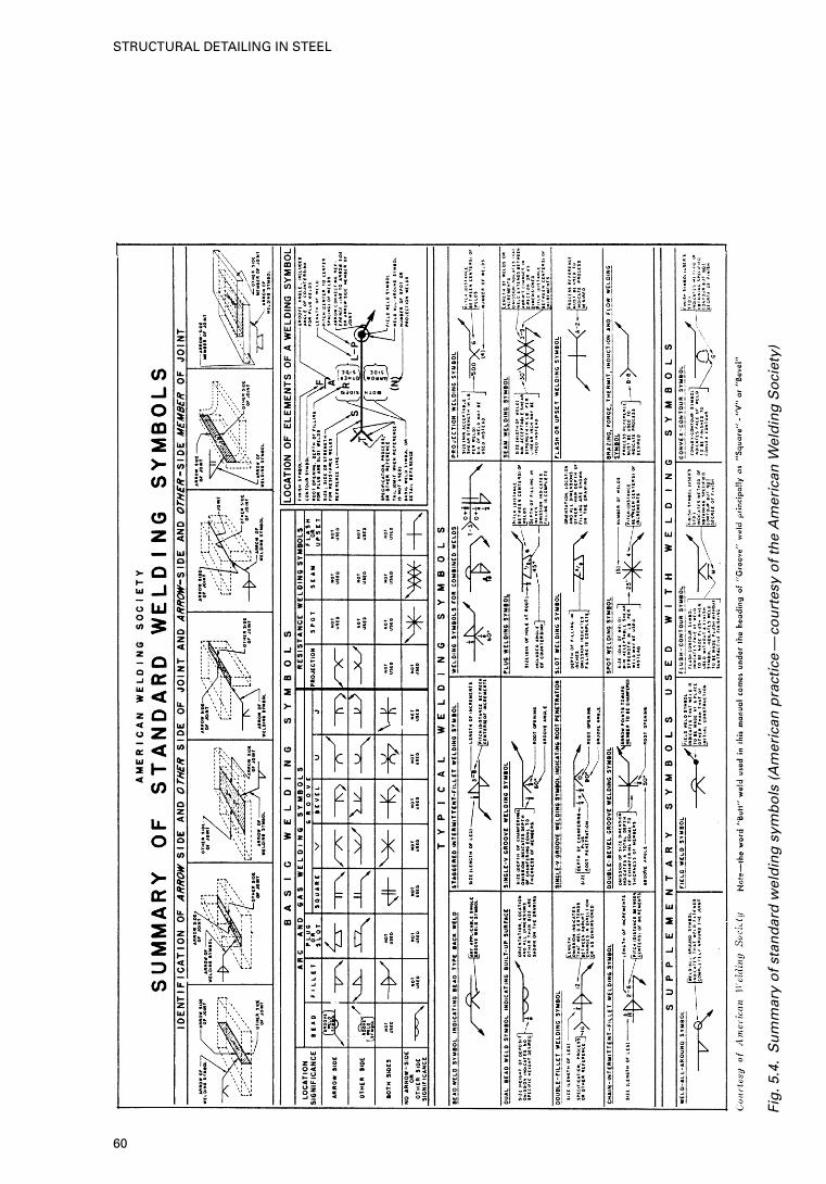
Fig
.5.4
.S
um
mar
y o
f st
and
ard
wel
din
g s
ymb
ols
(A
mer
ican
pra
ctic
e—
cou
rtes
y o
f th
e A
mer
ican
Wel
din
g S
oci
ety)
60
STRUCTURAL DETAILING IN STEEL
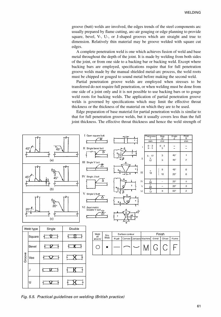
groove (butt) welds are involved, the edges trends of the steel components arcusually prepared by flame cutting, arc-air gouging or edge planning to providesquare, bevel, V-, U-, or J-shaped grooves which are straight and true todimension. Relatively thin material may be groove welded with square cutedges.
A complete penetration weld is one which achieves fusion of weld and basemetal throughout the depth of the joint. It is made by welding from both sidesof the joint, or from one side to a backing bar or backing weld. Except wherebacking bars are employed, specifications require that for full penetrationgroove welds made by the manual shielded metal-arc process, the weld rootsmust be chipped or gouged to sound metal before making the second weld.
Partial penetration groove welds are employed when stresses to betransferred do not require full penetration, or when welding must be done fromone side of a joint only and it is not possible to use backing bars or to gougeweld roots for backing welds. The application of partial penetration groovewelds is governed by specifications which may limit the effective throatthickness or the thickness of the material on which they are to be used.
Edge preparation of base material for partial penetration welds is similar tothat for full penetration groove welds, but it usually covers less than the fulljoint thickness. The effective throat thickness and hence the weld strength of
Fig. 5.5. Practical guidelines on welding (British practice)
61
WELDING
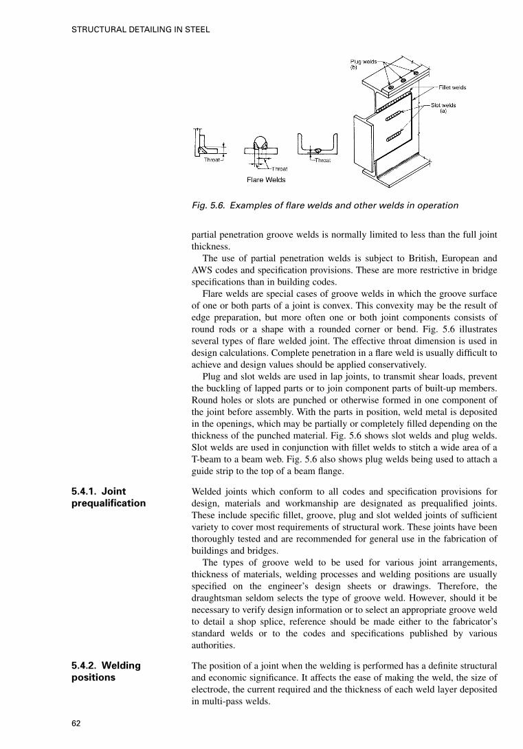
partial penetration groove welds is normally limited to less than the full jointthickness.
The use of partial penetration welds is subject to British, European andAWS codes and specification provisions. These are more restrictive in bridgespecifications than in building codes.
Flare welds are special cases of groove welds in which the groove surfaceof one or both parts of a joint is convex. This convexity may be the result ofedge preparation, but more often one or both joint components consists ofround rods or a shape with a rounded corner or bend. Fig. 5.6 illustratesseveral types of flare welded joint. The effective throat dimension is used indesign calculations. Complete penetration in a flare weld is usually difficult toachieve and design values should be applied conservatively.
Plug and slot welds are used in lap joints, to transmit shear loads, preventthe buckling of lapped parts or to join component parts of built-up members.Round holes or slots are punched or otherwise formed in one component ofthe joint before assembly. With the parts in position, weld metal is depositedin the openings, which may be partially or completely filled depending on thethickness of the punched material. Fig. 5.6 shows slot welds and plug welds.Slot welds are used in conjunction with fillet welds to stitch a wide area of aT-beam to a beam web. Fig. 5.6 also shows plug welds being used to attach aguide strip to the top of a beam flange.
5.4.1. Joint
prequalification
Welded joints which conform to all codes and specification provisions fordesign, materials and workmanship are designated as prequalified joints.These include specific fillet, groove, plug and slot welded joints of sufficientvariety to cover most requirements of structural work. These joints have beenthoroughly tested and are recommended for general use in the fabrication ofbuildings and bridges.
The types of groove weld to be used for various joint arrangements,thickness of materials, welding processes and welding positions are usuallyspecified on the engineer’s design sheets or drawings. Therefore, thedraughtsman seldom selects the type of groove weld. However, should it benecessary to verify design information or to select an appropriate groove weldto detail a shop splice, reference should be made either to the fabricator’sstandard welds or to the codes and specifications published by variousauthorities.
5.4.2. Welding
positions
The position of a joint when the welding is performed has a definite structuraland economic significance. It affects the ease of making the weld, the size ofelectrode, the current required and the thickness of each weld layer depositedin multi-pass welds.
Fig. 5.6. Examples of flare welds and other welds in operation
62
STRUCTURAL DETAILING IN STEEL
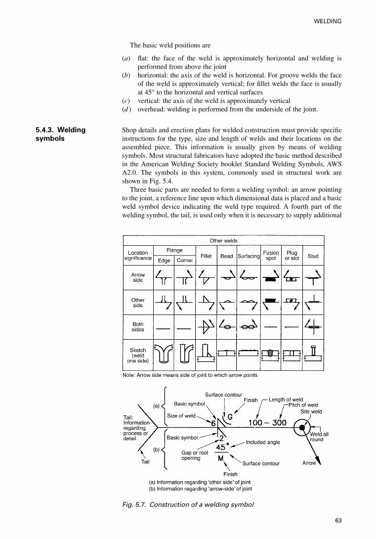
The basic weld positions are
(a) flat: the face of the weld is approximately horizontal and welding isperformed from above the joint
(b) horizontal: the axis of the weld is horizontal. For groove welds the faceof the weld is approximately vertical; for fillet welds the face is usuallyat 45° to the horizontal and vertical surfaces
(c) vertical: the axis of the weld is approximately vertical(d ) overhead: welding is performed from the underside of the joint.
5.4.3. Welding
symbols
Shop details and erection plans for welded construction must provide specificinstructions for the type, size and length of welds and their locations on theassembled piece. This information is usually given by means of weldingsymbols. Most structural fabricators have adopted the basic method describedin the American Welding Society booklet Standard Welding Symbols, AWSA2.0. The symbols in this system, commonly used in structural work areshown in Fig. 5.4.
Three basic parts are needed to form a welding symbol: an arrow pointingto the joint, a reference line upon which dimensional data is placed and a basicweld symbol device indicating the weld type required. A fourth part of thewelding symbol, the tail, is used only when it is necessary to supply additional
Fig. 5.7. Construction of a welding symbol
63
WELDING
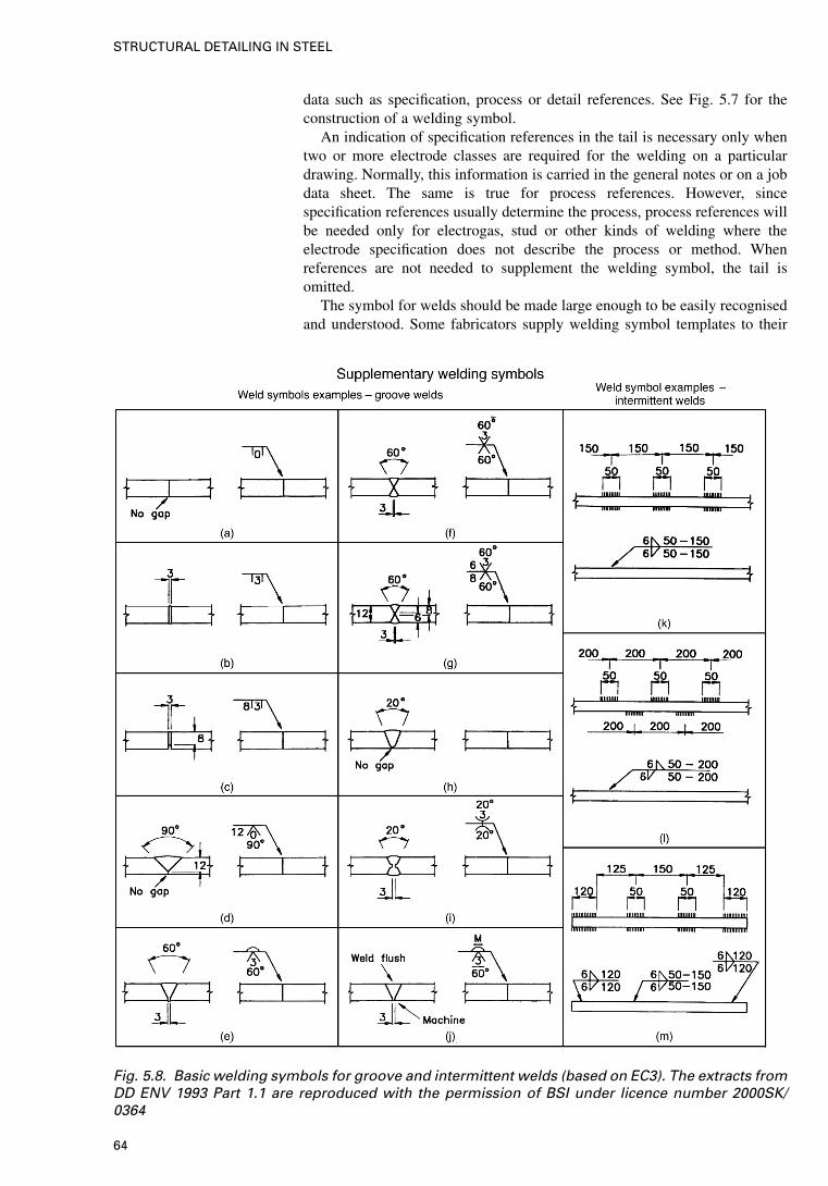
data such as specification, process or detail references. See Fig. 5.7 for theconstruction of a welding symbol.
An indication of specification references in the tail is necessary only whentwo or more electrode classes are required for the welding on a particulardrawing. Normally, this information is carried in the general notes or on a jobdata sheet. The same is true for process references. However, sincespecification references usually determine the process, process references willbe needed only for electrogas, stud or other kinds of welding where theelectrode specification does not describe the process or method. Whenreferences are not needed to supplement the welding symbol, the tail isomitted.
The symbol for welds should be made large enough to be easily recognisedand understood. Some fabricators supply welding symbol templates to their
Fig. 5.8. Basic welding symbols for groove and intermittent welds (based on EC3). The extracts fromDD ENV 1993 Part 1.1 are reproduced with the permission of BSI under licence number 2000SK/0364
64
STRUCTURAL DETAILING IN STEEL
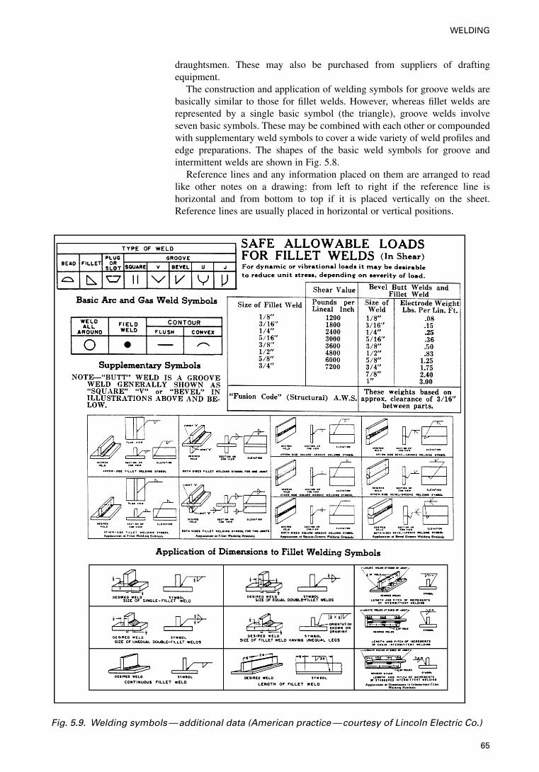
draughtsmen. These may also be purchased from suppliers of draftingequipment.
The construction and application of welding symbols for groove welds arebasically similar to those for fillet welds. However, whereas fillet welds arerepresented by a single basic symbol (the triangle), groove welds involveseven basic symbols. These may be combined with each other or compoundedwith supplementary weld symbols to cover a wide variety of weld profiles andedge preparations. The shapes of the basic weld symbols for groove andintermittent welds are shown in Fig. 5.8.
Reference lines and any information placed on them are arranged to readlike other notes on a drawing: from left to right if the reference line ishorizontal and from bottom to top if it is placed vertically on the sheet.Reference lines are usually placed in horizontal or vertical positions.
Fig. 5.9. Welding symbols—additional data (American practice—courtesy of Lincoln Electric Co.)
65
WELDING
The arrow may be located at the right or left end of the reference line andmay point upward or downward from it. The arrow is drawn at an angle ofabout 45° to the reference line, except when some other arrangement isnecessary to avoid crowding a portion of the drawing. The arrow head shouldnever be placed on the reference line or on a continuous extension of thereference line. Some angular break should always be employed.
Weld dimensions are placed on the welding symbol with the weld size tothe left of the basic weld symbol or device and the weld length to the right.
Weld dimensions are placed on the same side of the reference line as thedevice. When a device is required on both sides of the reference line and theweld size and length are identical for the arrow and other side of the joint, itis unnecessary to repeat dimensional data above and below the referenceline.
Additional data on welding symbols, as used specifically by LincolnElectric Co., USA, is given in Fig. 5.9.
66
STRUCTURAL DETAILING IN STEEL
6. Design detailing of major steel
components
This chapter gives a comparative study of detailing practices for major steelcomponents such as beams, girders, columns, trusses, and various fastenings.Three major codes are considered and they are based on British, European andAmerican practices. Both bolted and welded connections or fastenings aregiven as practised under the BS 5950, EC3 and AISC and LRFD Codes.
67
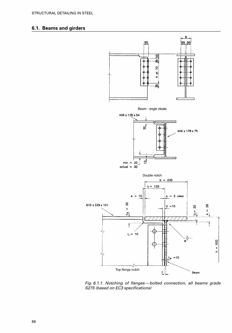
6.1. Beams and girders
Fig. 6.1.1. Notching of flanges—bolted connection, all beams gradeS275 (based on EC3 specifications)
68
STRUCTURAL DETAILING IN STEEL
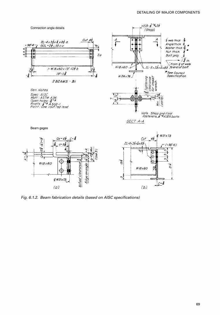
Fig. 6.1.2. Beam fabrication details (based on AISC specifications)
69
DETAILING OF MAJOR COMPONENTS
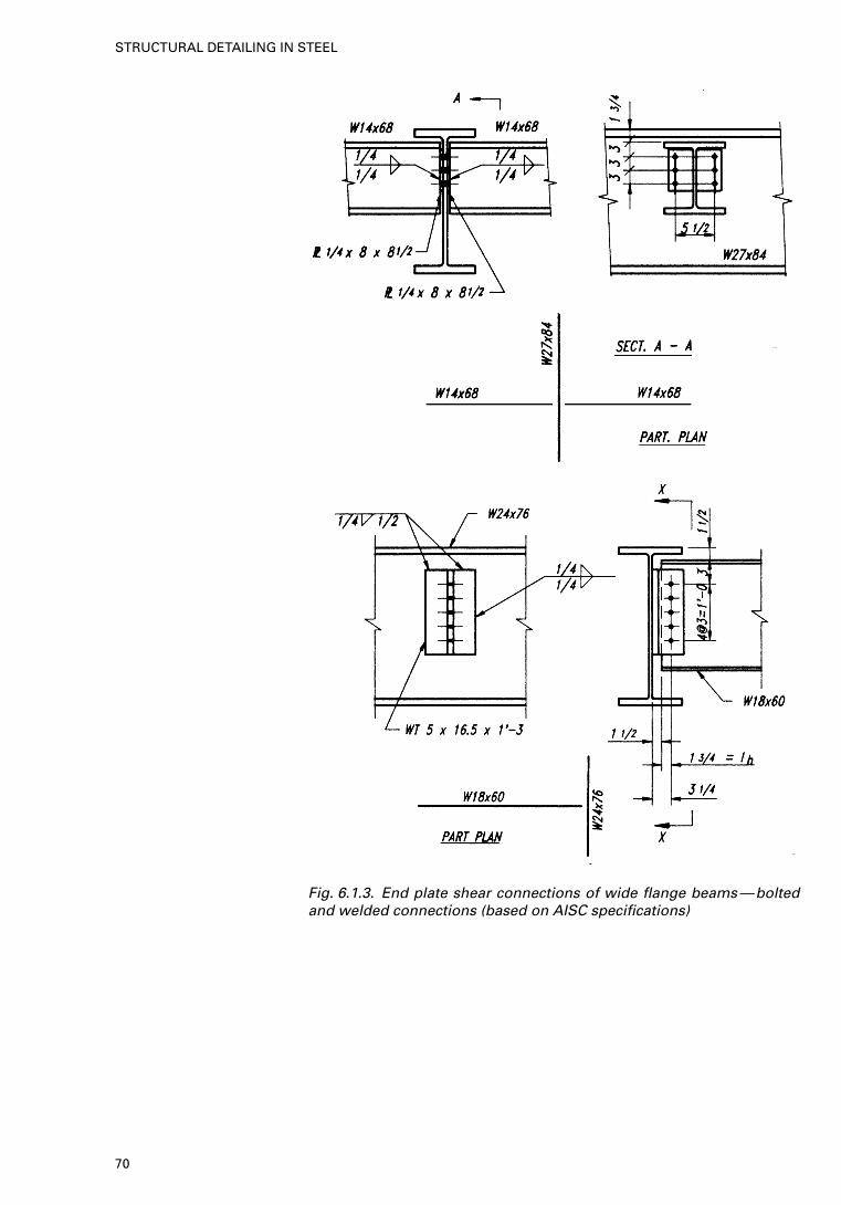
Fig. 6.1.3. End plate shear connections of wide flange beams—boltedand welded connections (based on AISC specifications)
70
STRUCTURAL DETAILING IN STEEL
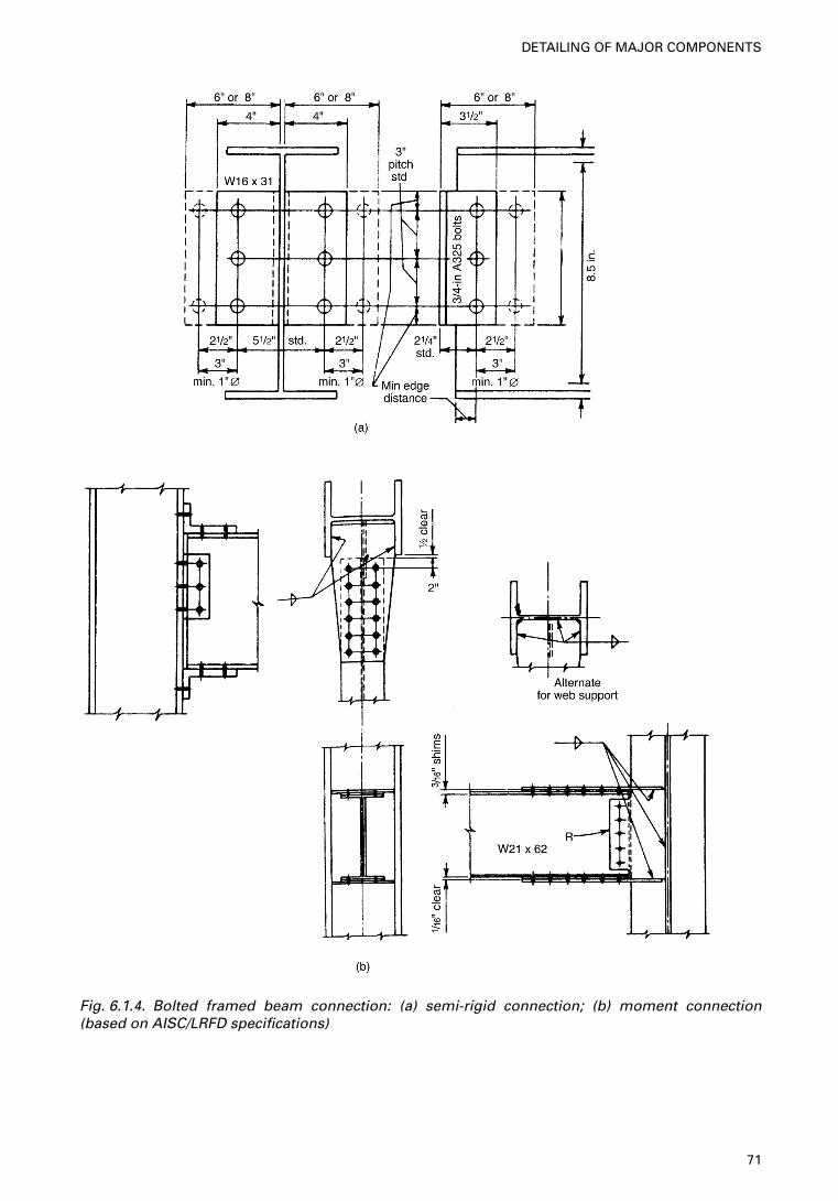
Fig. 6.1.4. Bolted framed beam connection: (a) semi-rigid connection; (b) moment connection(based on AISC/LRFD specifications)
71
DETAILING OF MAJOR COMPONENTS
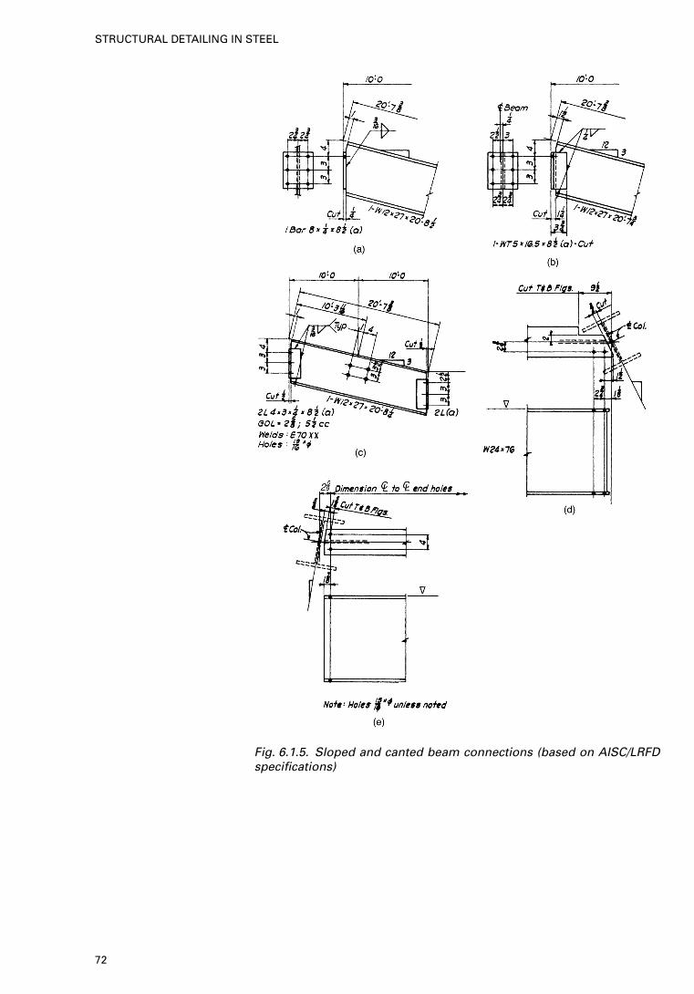
Fig. 6.1.5. Sloped and canted beam connections (based on AISC/LRFDspecifications)
72
STRUCTURAL DETAILING IN STEEL
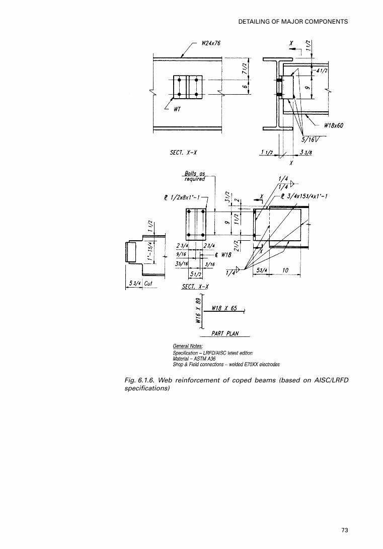
Fig. 6.1.6. Web reinforcement of coped beams (based on AISC/LRFDspecifications)
73
DETAILING OF MAJOR COMPONENTS
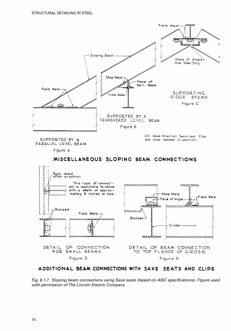
Fig. 6.1.7. Sloping beam connections using Saxe seats (based on AISC specifications). Figure usedwith permission of The Lincoln Electric Company
74
STRUCTURAL DETAILING IN STEEL
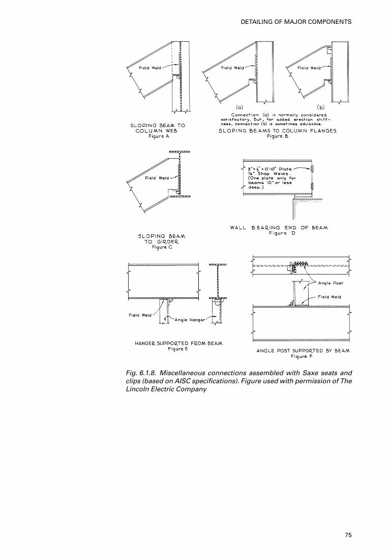
Fig. 6.1.8. Miscellaneous connections assembled with Saxe seats andclips (based on AISC specifications). Figure used with permission of TheLincoln Electric Company
75
DETAILING OF MAJOR COMPONENTS
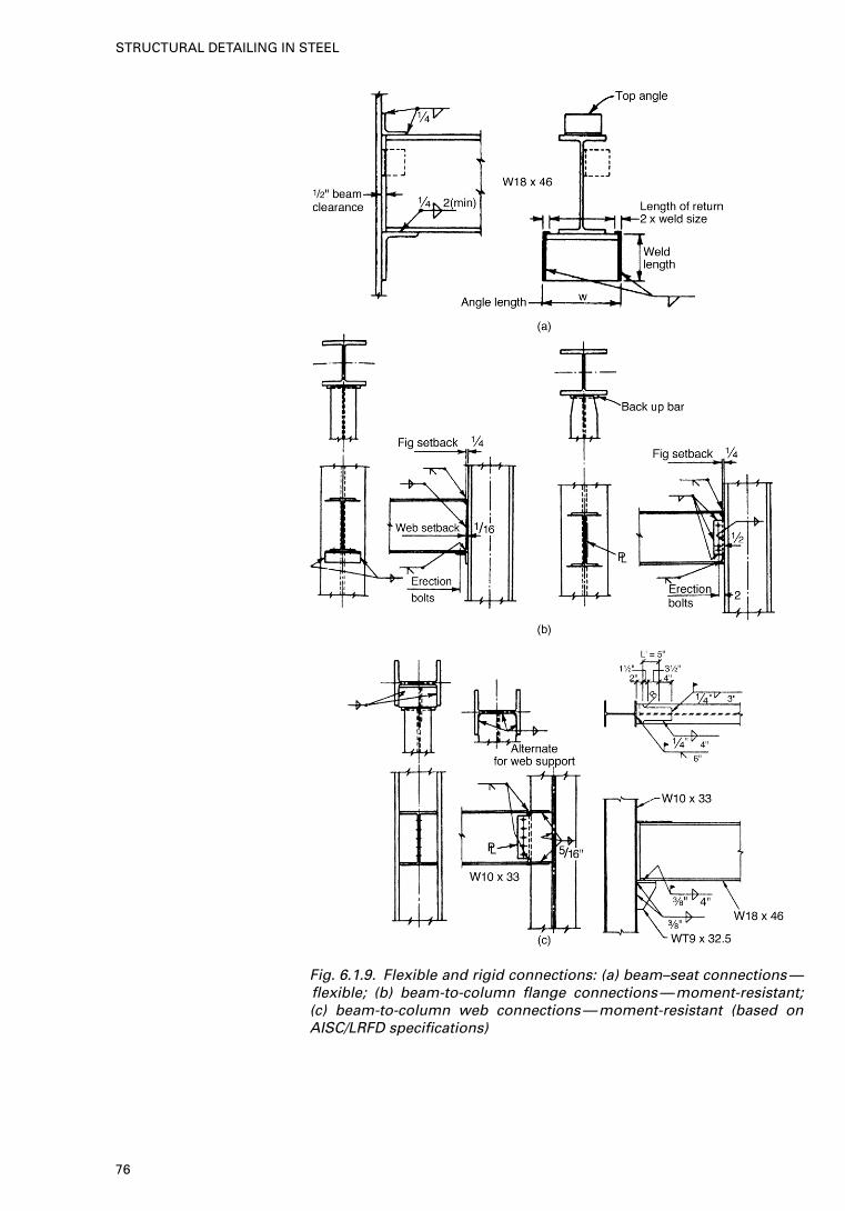
Fig. 6.1.9. Flexible and rigid connections: (a) beam–seat connections—flexible; (b) beam-to-column flange connections—moment-resistant;(c) beam-to-column web connections—moment-resistant (based onAISC/LRFD specifications)
76
STRUCTURAL DETAILING IN STEEL
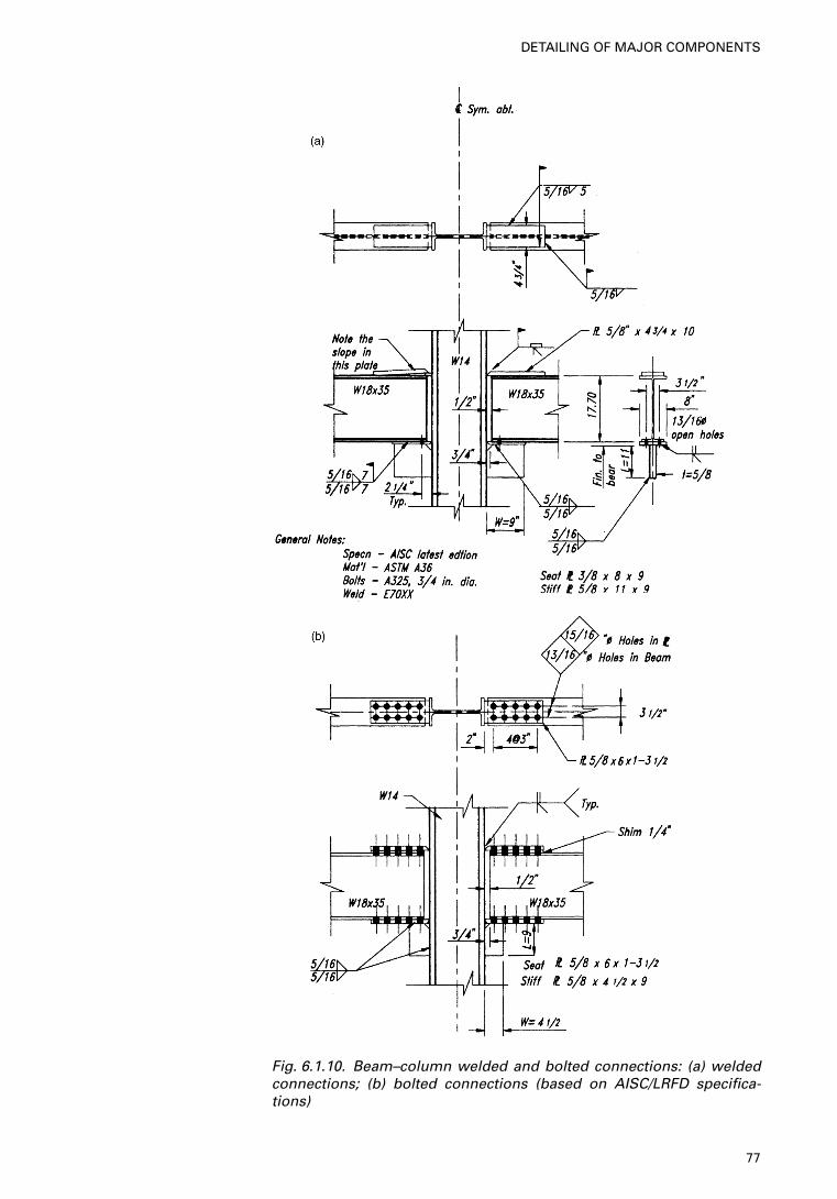
Fig. 6.1.10. Beam–column welded and bolted connections: (a) weldedconnections; (b) bolted connections (based on AISC/LRFD specifica-tions)
77
DETAILING OF MAJOR COMPONENTS
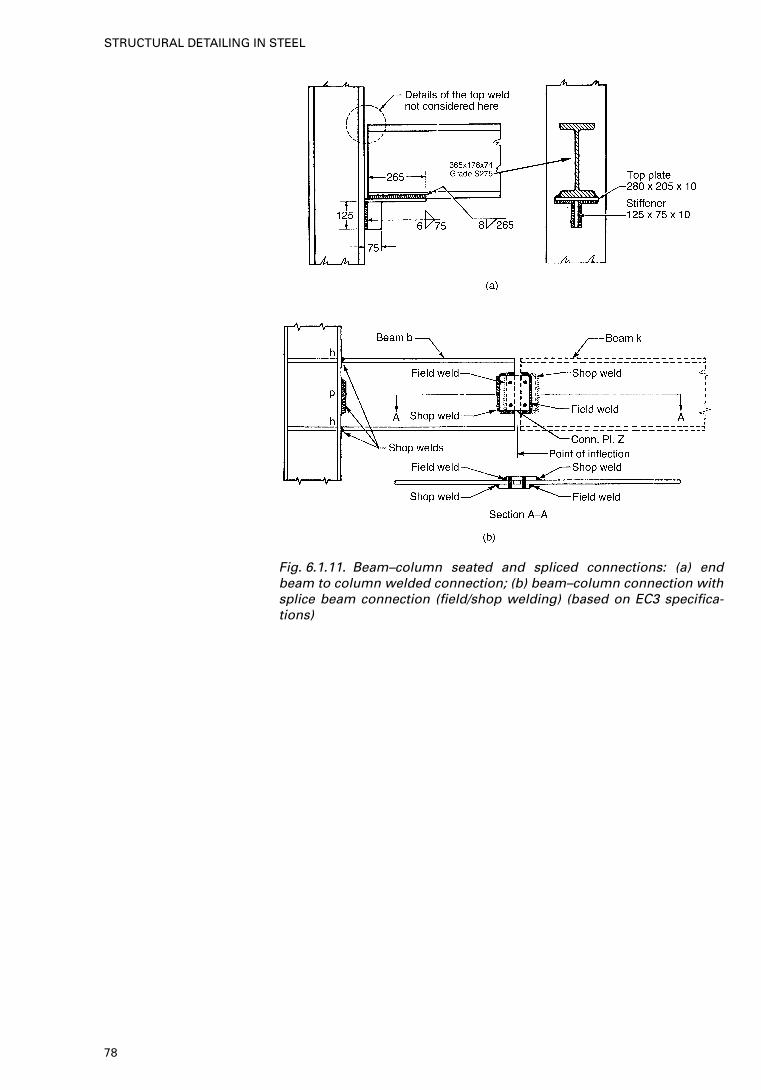
Fig. 6.1.11. Beam–column seated and spliced connections: (a) endbeam to column welded connection; (b) beam–column connection withsplice beam connection (field/shop welding) (based on EC3 specifica-tions)
78
STRUCTURAL DETAILING IN STEEL
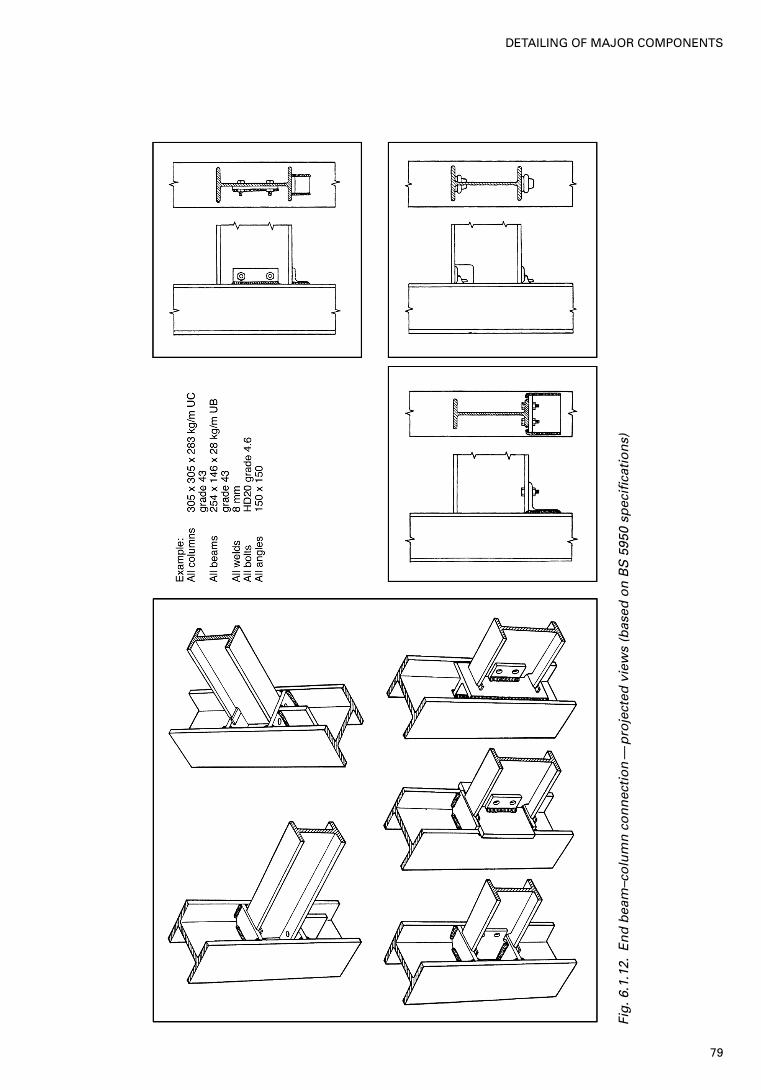
Fig
.6.1
.12.
En
d b
eam
–co
lum
n c
on
nec
tio
n—
pro
ject
ed v
iew
s (b
ased
on
BS
5950
sp
ecifi
cati
on
s)
79
DETAILING OF MAJOR COMPONENTS

6.1A. Detailing of welded plate girders
Fig. 6.1.13. Spandrel beam to columns (based on BS 5950 specifications)
80
STRUCTURAL DETAILING IN STEEL
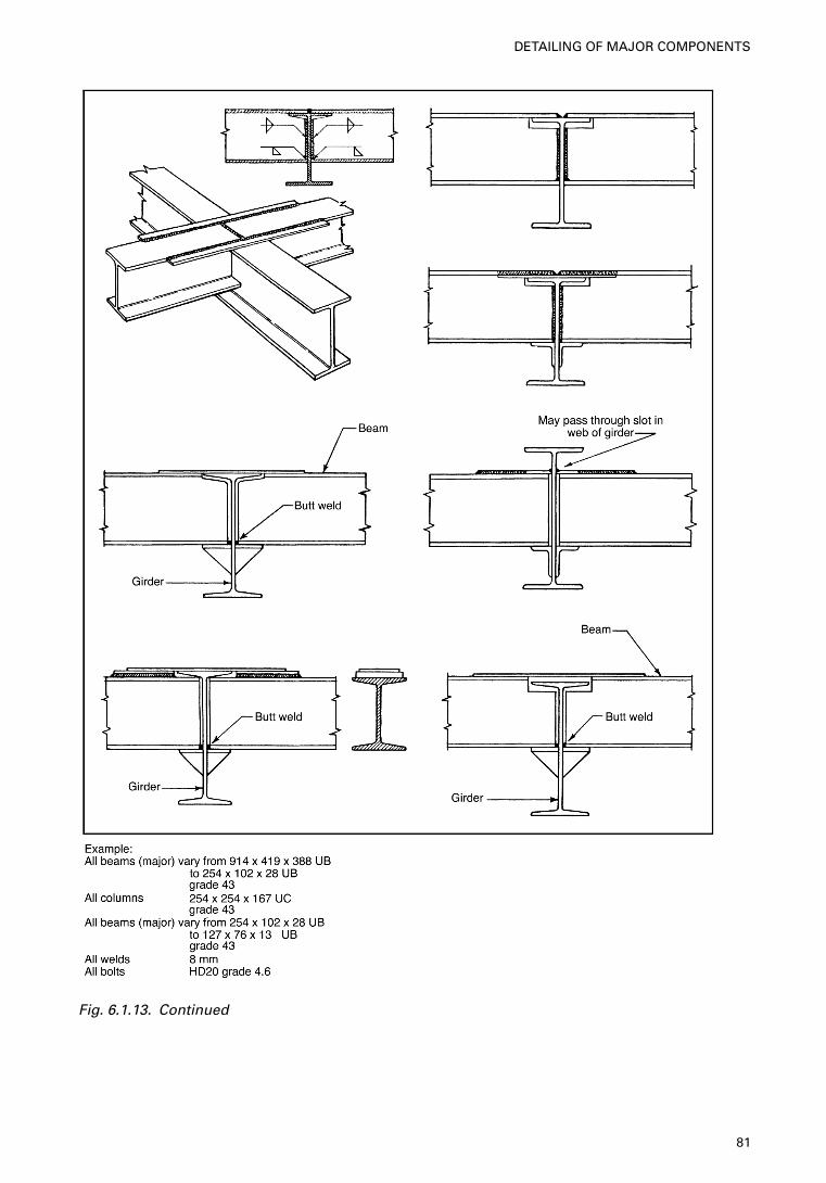
Fig. 6.1.13. Continued
81
DETAILING OF MAJOR COMPONENTS
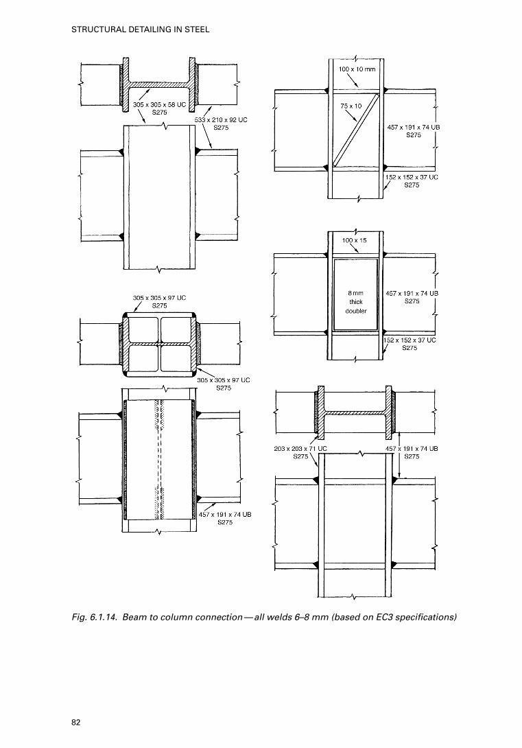
Fig. 6.1.14. Beam to column connection—all welds 6–8 mm (based on EC3 specifications)
82
STRUCTURAL DETAILING IN STEEL
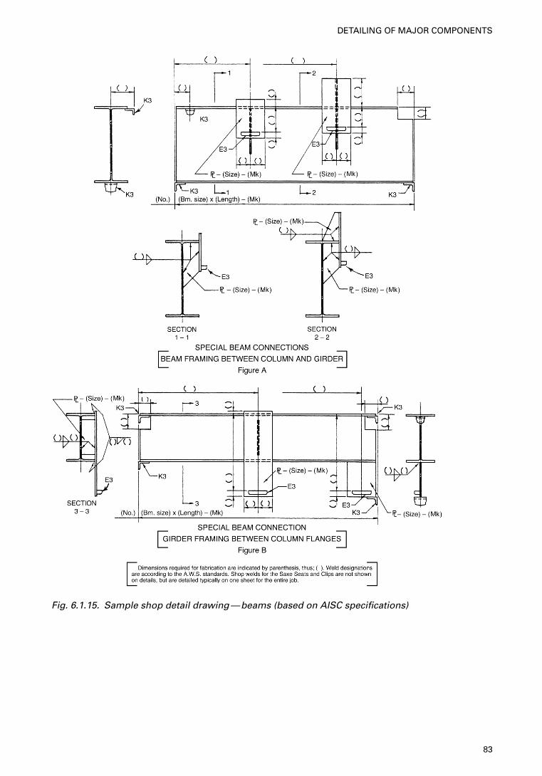
Fig. 6.1.15. Sample shop detail drawing—beams (based on AISC specifications)
83
DETAILING OF MAJOR COMPONENTS
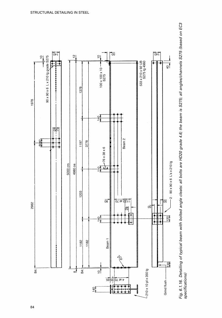
Fig
.6.1
.16.
Det
ailin
g o
f ty
pic
al b
eam
wit
h b
olt
ed a
ng
le c
leat
s: a
ll b
olt
s ar
e H
D20
gra
de
4.6;
th
e b
eam
is
S27
5; a
ll an
gle
s/ch
ann
els
S27
5 (b
ased
on
EC
3sp
ecifi
cati
on
s)
84
STRUCTURAL DETAILING IN STEEL
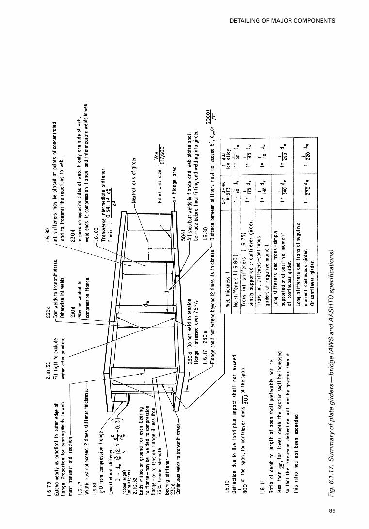
Fig
.6.1
.17.
Su
mm
ary
of
pla
te g
ird
ers
—b
rid
ge
(AW
S a
nd
AA
SH
TO
sp
ecifi
cati
on
s)
85
DETAILING OF MAJOR COMPONENTS
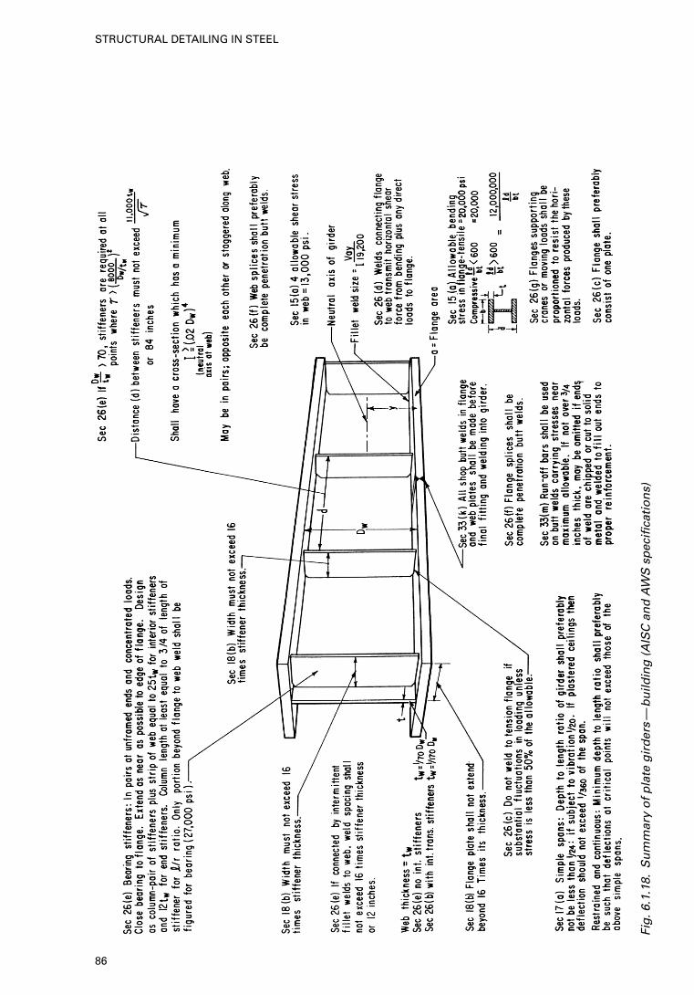
Fig
.6.1
.18.
Su
mm
ary
of
pla
te g
ird
ers
—b
uild
ing
(A
ISC
an
d A
WS
sp
ecifi
cati
on
s)
86
STRUCTURAL DETAILING IN STEEL

Fig. 6.1.19. Plate girders (symmetrical flanges), welded (based onBS 5950 specifications)
87
DETAILING OF MAJOR COMPONENTS
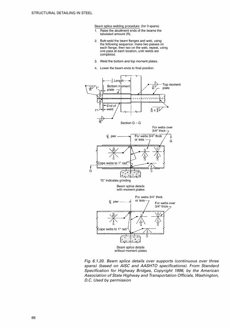
Fig. 6.1.20. Beam splice details over supports (continuous over threespans) (based on AISC and AASHTO specifications). From StandardSpecification for Highway Bridges, Copyright 1996, by the AmericanAssociation of State Highway and Transportation Officials, Washington,D.C. Used by permission
88
STRUCTURAL DETAILING IN STEEL
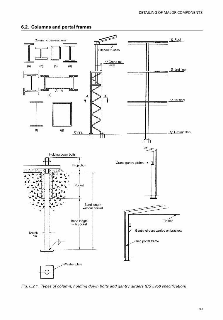
6.2. Columns and portal frames
Fig. 6.2.1. Types of column, holding down bolts and gantry girders (BS 5950 specification)
89
DETAILING OF MAJOR COMPONENTS
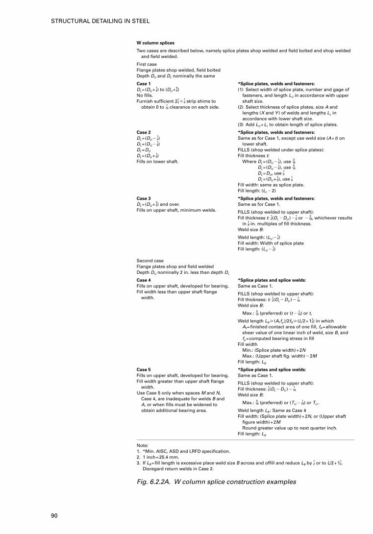
W column splices
Two cases are described below, namely splice plates shop welded and field bolted and shop weldedand field welded.
First caseFlange plates shop welded, field boltedDepth DU and DL nominally the same
Case 1
DL=(DU+ 14) to (DU+ 5
8)No fills.Furnish sufficient 21
2 �18 strip shims to
obtain 0 to 116 clearance on each side.
*Splice plates, welds and fasteners:
(1) Select width of splice plate, number and gage offasteners, and length LU in accordance with uppershaft size.
(2) Select thickness of splice plates, size A andlengths (X and Y ) of welds and lengths LL inaccordance with lower shaft size.
(3) Add LU+LL to obtain length of splice plates.
Case 2
DL=(DU �14)
DL=(DU �18)
DL=DU
DL=(DU+ 18)
Fills on lower shaft.
*Splice plates, welds and fasteners:
Same as for Case 1, except use weld size (A+t) onlower shaft.
FILLS (shop welded under splice plates):Fill thickness t:
Where DL=(DU �14), use 3
16
DL=(DU �18), use 3
16
DL=DU, use 18DL=(DU+ 1
8), use 18Fill width: same as splice plate.Fill length: (LL �2)
Case 3
DL=(DU+ 34) and over.
Fills on upper shaft, minimum welds.
*Splice plates, welds and fasteners:
Same as for Case 1.
FILLS (shop welded to upper shaft):Fill thickness t: 1
2(DL �DU )�18 or �
316, whichever results
in 18-in. multiples of fill thickness.Weld size B:
Weld length: (LU �14)
Fill width: Width of splice plateFill length: (LU �
14)
Second caseFlange plates shop and field weldedDepth DU nominally 2 in. less than depth DL
Case 4
Fills on upper shaft, developed for bearing.Fill width less than upper shaft flange
width.
*Splice plates and splice welds:
Same as Case 1.
FILLS (shop welded to upper shaft):Fill thickness: t: 1
2(DL �DU )�116
Weld size B:
Max.: 516 (preferred) or (t�
116) or t,
Weld length LB � (Af fp )/2fR � (L/2+112) in which
Af=finished contact area of one fill, fR=allowableshear value of one linear inch of weld, size B, andfp=computed bearing stress in fill
Fill widthMin.: (Splice plate width)+2NMax.: (Upper shaft fig. width)�2M
Fill length: LB
Case 5
Fills on upper shaft, developed for bearing.Fill width greater than upper shaft flange
width.Use Case 5 only when spaces M and N,
Case 4, are inadequate for welds B andA, or when fills must be widened toobtain additional bearing area.
*Splice plates and splice welds:
Same as Case 1.
FILLS (shop welded to upper shaft):Fill thickness: 1
2(DL �DU )�116
Weld size B:
Max.: 516 (preferred) or (TU �
116) or TU .
Weld length LB : Same as Case 4Fill width: (Splice plate width)+2N, or (Upper shaft
figure width)+2MRound greater value up to next quarter inch.
Fill length: LB
Note:1. *Min. AISC, ASD and LRFD specification.2. 1 inch=25.4 mm.3. If LB=fill length is excessive place weld size B across and offill and reduce LB by 1
2 or to L/2+112.
Disregard return welds in Case 2.
Fig. 6.2.2A. W column splice construction examples
90
STRUCTURAL DETAILING IN STEEL
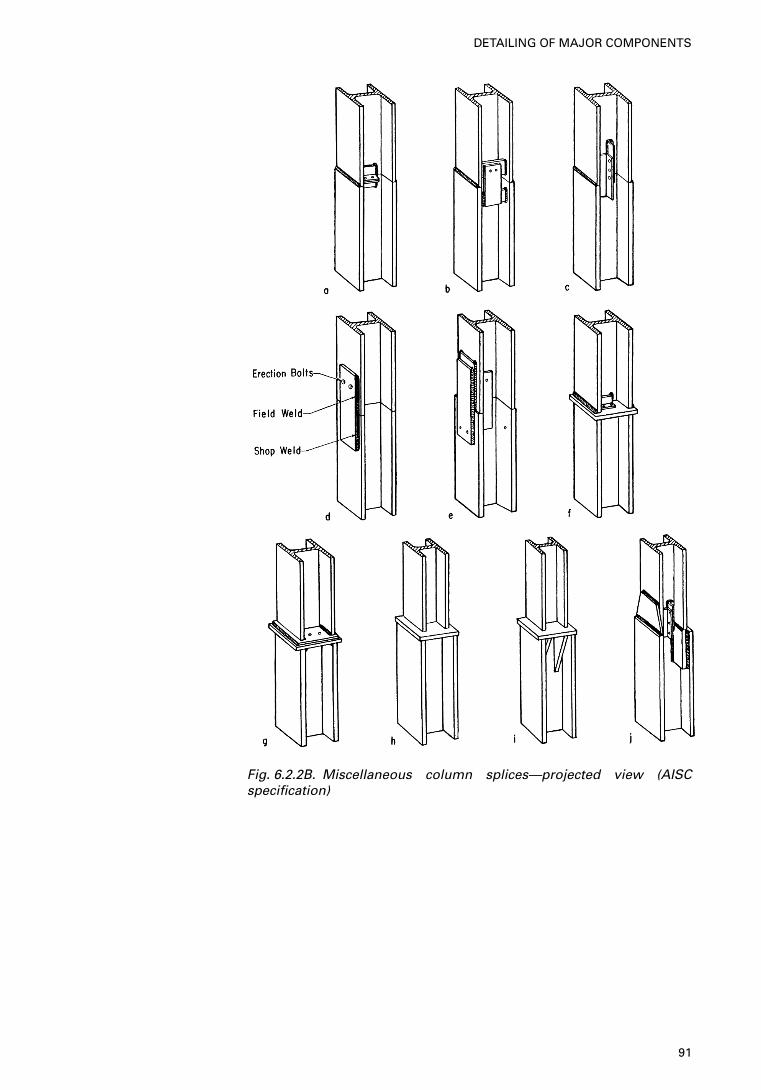
Fig. 6.2.2B. Miscellaneous column splices—projected view (AISCspecification)
91
DETAILING OF MAJOR COMPONENTS
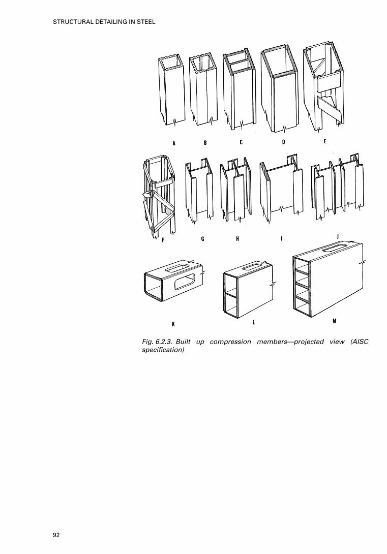
Fig. 6.2.3. Built up compression members—projected view (AISCspecification)
92
STRUCTURAL DETAILING IN STEEL
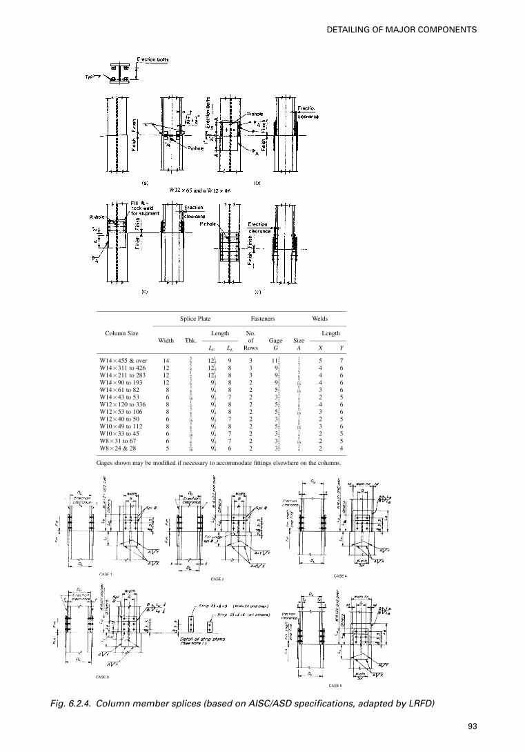
Splice Plate Fasteners Welds
Column Size Length No. LengthWidth Thk. of Gage Size
LU LL Rows G A X Y
W14�455 & over 14 58 121
4 9 3 1112
12 5 7
W14�311 to 426 12 58 121
4 8 3 912
12 4 6
W14�211 to 283 12 12 121
4 8 3 912
38 4 6
W14�90 to 193 12 38 91
4 8 2 912
516 4 6
W14�61 to 82 8 38 91
4 8 2 512
516 3 6
W14�43 to 53 6 516 91
4 7 2 312
14 2 5
W12�120 to 336 8 12 91
4 8 2 512
38 4 6
W12�53 to 106 8 38 91
4 8 2 512
516 3 6
W12�40 to 50 6 516 91
4 7 2 312
14 2 5
W10�49 to 112 8 38 91
4 8 2 512
516 3 6
W10�33 to 45 6 516 91
4 7 2 312
14 2 5
W8�31 to 67 6 38 91
4 7 2 312
516 2 5
W8�24 & 28 5 516 91
4 6 2 312
14 2 4
Gages shown may be modified if necessary to accommodate fittings elsewhere on the columns.
Fig. 6.2.4. Column member splices (based on AISC/ASD specifications, adapted by LRFD)
93
DETAILING OF MAJOR COMPONENTS
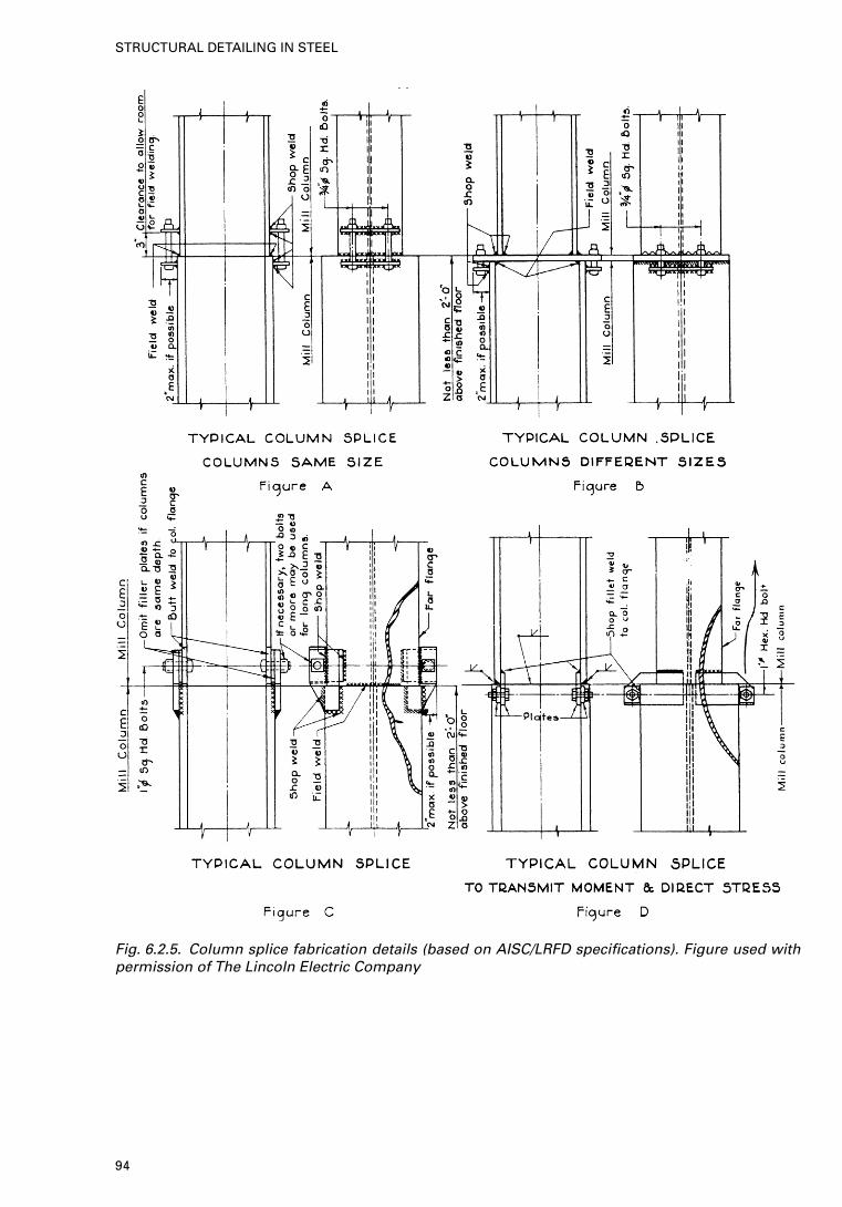
Fig. 6.2.5. Column splice fabrication details (based on AISC/LRFD specifications). Figure used withpermission of The Lincoln Electric Company
94
STRUCTURAL DETAILING IN STEEL
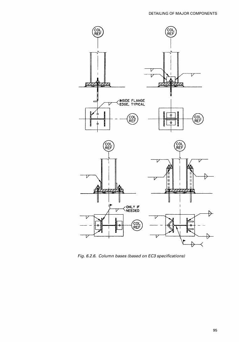
Fig. 6.2.6. Column bases (based on EC3 specifications)
95
DETAILING OF MAJOR COMPONENTS
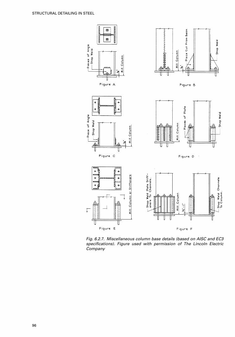
Fig. 6.2.7. Miscellaneous column base details (based on AISC and EC3specifications). Figure used with permission of The Lincoln ElectricCompany
96
STRUCTURAL DETAILING IN STEEL
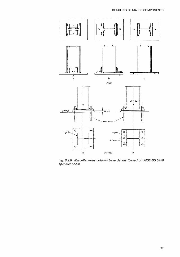
Fig. 6.2.8. Miscellaneous column base details (based on AISC/BS 5950specifications)
97
DETAILING OF MAJOR COMPONENTS
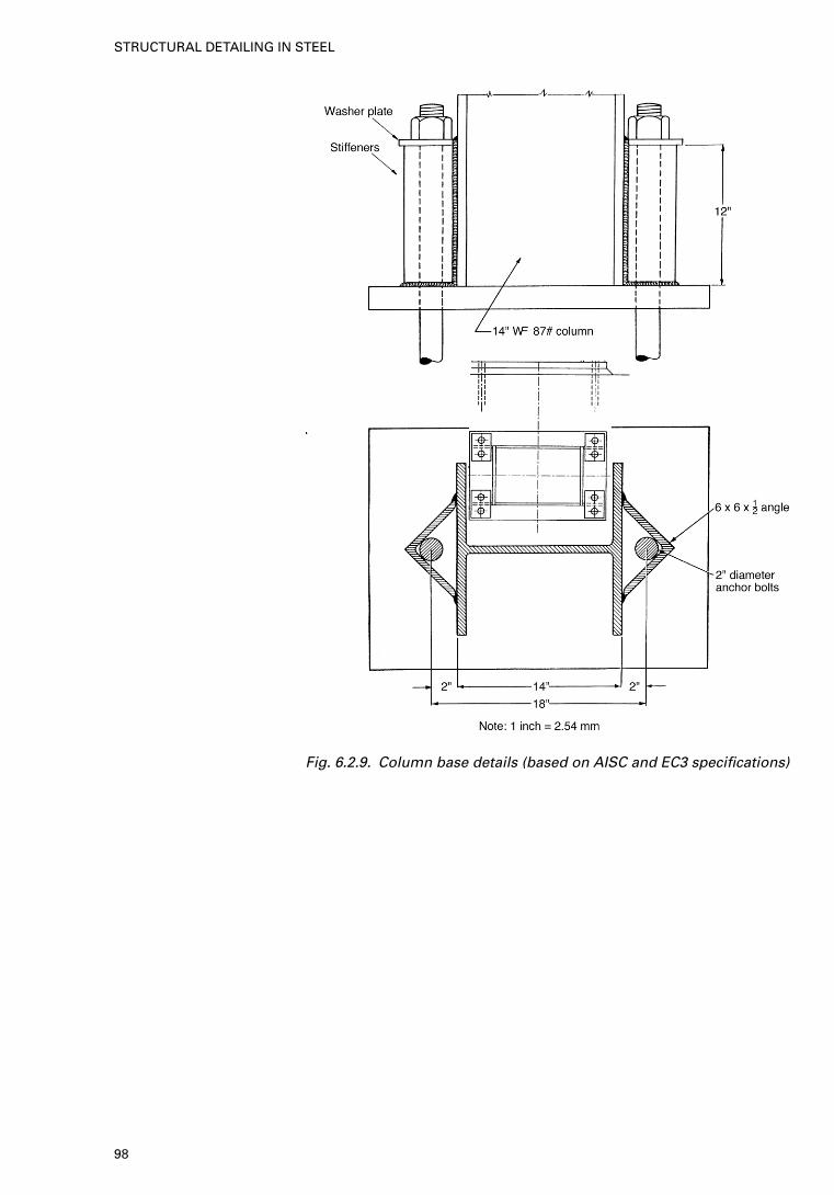
Fig. 6.2.9. Column base details (based on AISC and EC3 specifications)
98
STRUCTURAL DETAILING IN STEEL
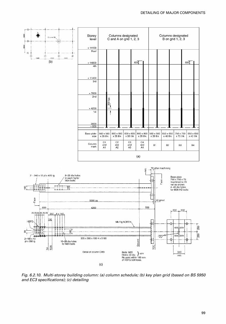
Fig. 6.2.10. Multi-storey building column: (a) column schedule; (b) key plan grid (based on BS 5950and EC3 specifications); (c) detailing
99
DETAILING OF MAJOR COMPONENTS
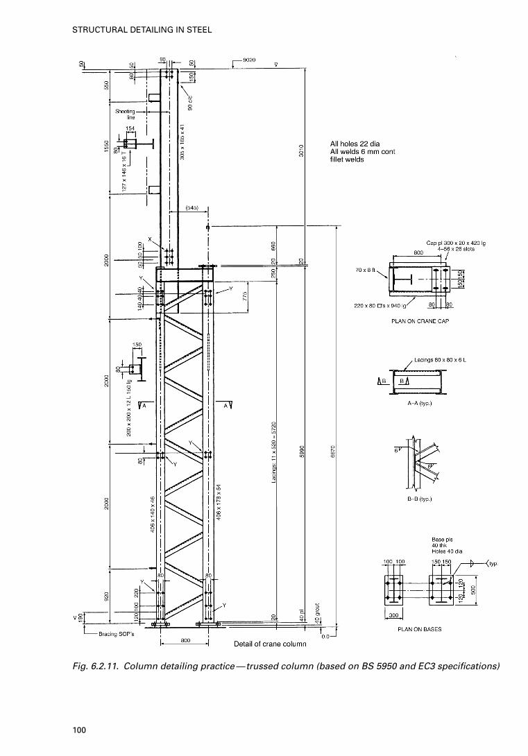
Fig. 6.2.11. Column detailing practice—trussed column (based on BS 5950 and EC3 specifications)
100
STRUCTURAL DETAILING IN STEEL
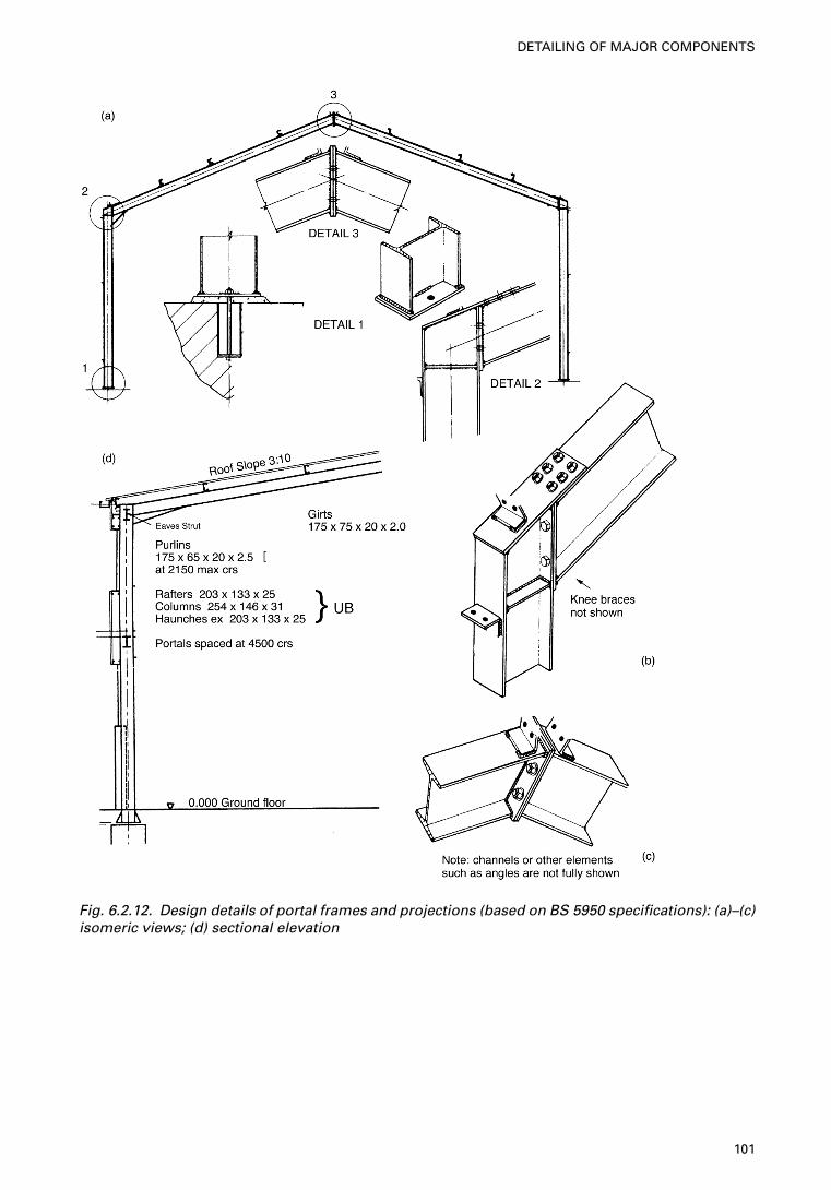
Fig. 6.2.12. Design details of portal frames and projections (based on BS 5950 specifications): (a)–(c)isomeric views; (d) sectional elevation
101
DETAILING OF MAJOR COMPONENTS
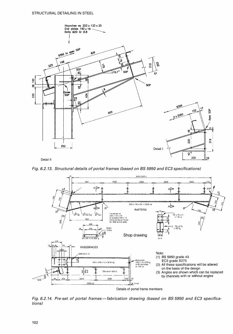
Fig. 6.2.13. Structural details of portal frames (based on BS 5950 and EC3 specifications)
Fig. 6.2.14. Pre-set of portal frames—fabrication drawing (based on BS 5950 and EC3 specifica-tions)
102
STRUCTURAL DETAILING IN STEEL
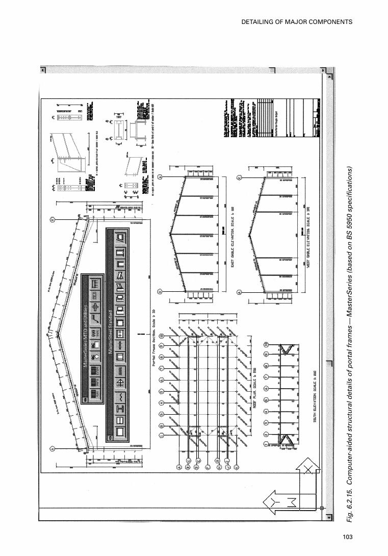
Fig
.6.2
.15.
Co
mp
ute
r-ai
ded
str
uct
ura
l det
ails
of
po
rtal
fra
mes
—M
aste
rSer
ies
(bas
ed o
n B
S59
50 s
pec
ifica
tio
ns)
103
DETAILING OF MAJOR COMPONENTS
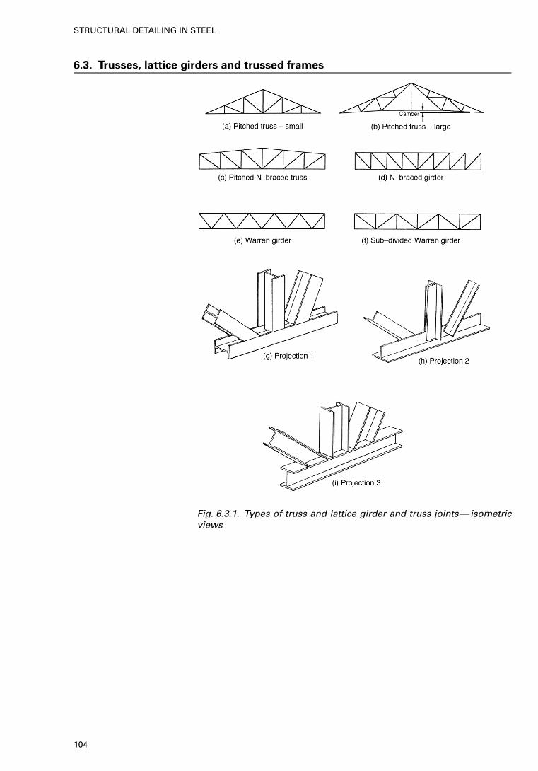
6.3. Trusses, lattice girders and trussed frames
Fig. 6.3.1. Types of truss and lattice girder and truss joints—isometricviews
104
STRUCTURAL DETAILING IN STEEL
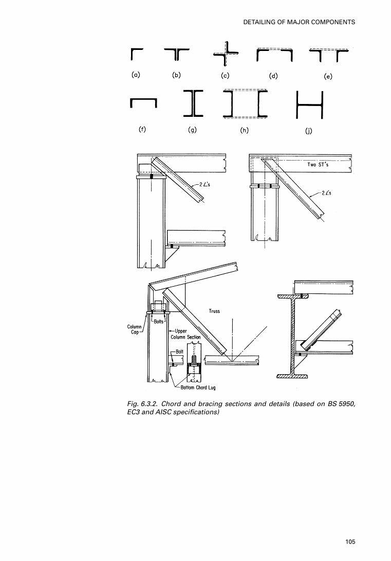
Fig. 6.3.2. Chord and bracing sections and details (based on BS 5950,EC3 and AISC specifications)
105
DETAILING OF MAJOR COMPONENTS
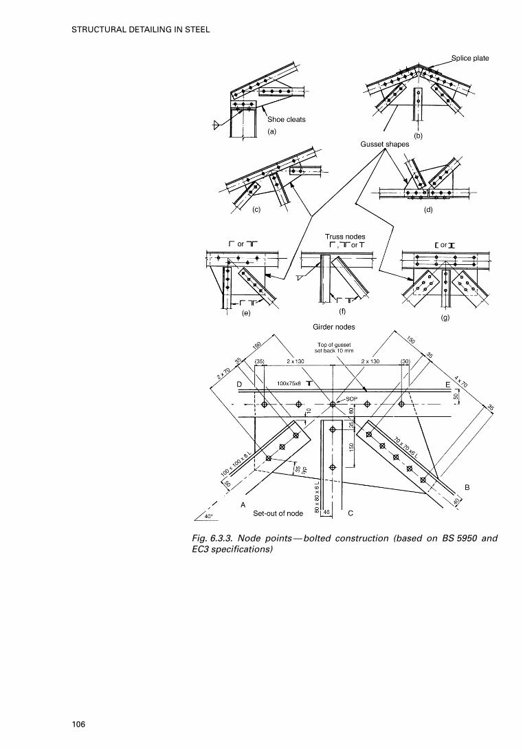
Fig. 6.3.3. Node points—bolted construction (based on BS 5950 andEC3 specifications)
106
STRUCTURAL DETAILING IN STEEL
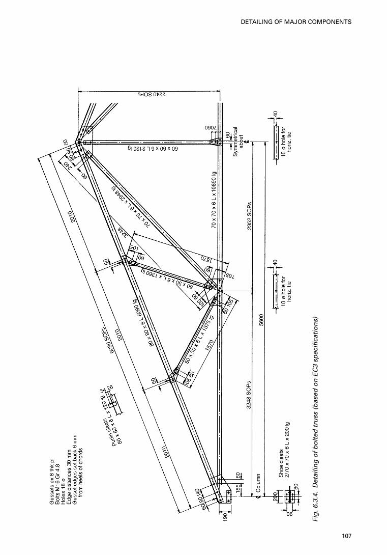
Fig
.6.3
.4.
Det
ailin
g o
f b
olt
ed t
russ
(b
ased
on
EC
3 sp
ecifi
cati
on
s)
107
DETAILING OF MAJOR COMPONENTS
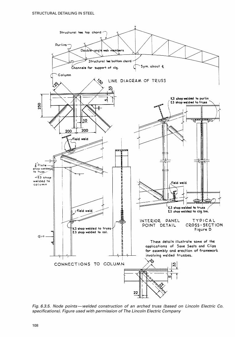
Fig. 6.3.5. Node points—welded construction of an arched truss (based on Lincoln Electric Co.specifications). Figure used with permission of The Lincoln Electric Company
108
STRUCTURAL DETAILING IN STEEL
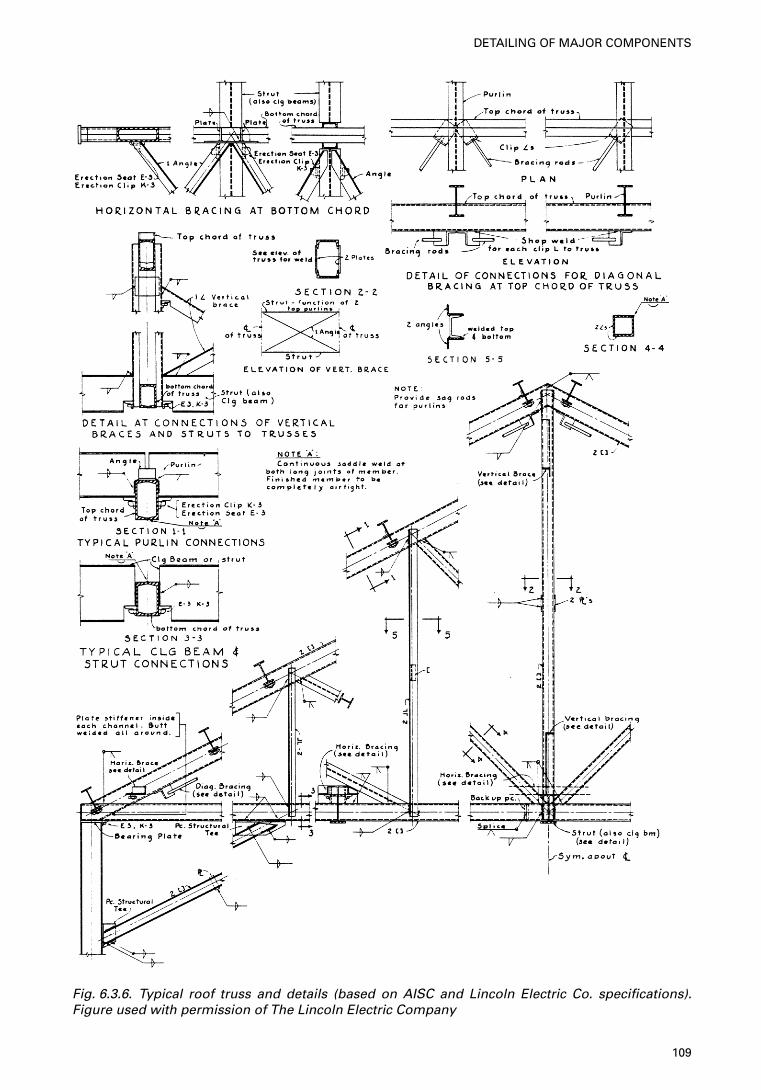
Fig. 6.3.6. Typical roof truss and details (based on AISC and Lincoln Electric Co. specifications).Figure used with permission of The Lincoln Electric Company
109
DETAILING OF MAJOR COMPONENTS
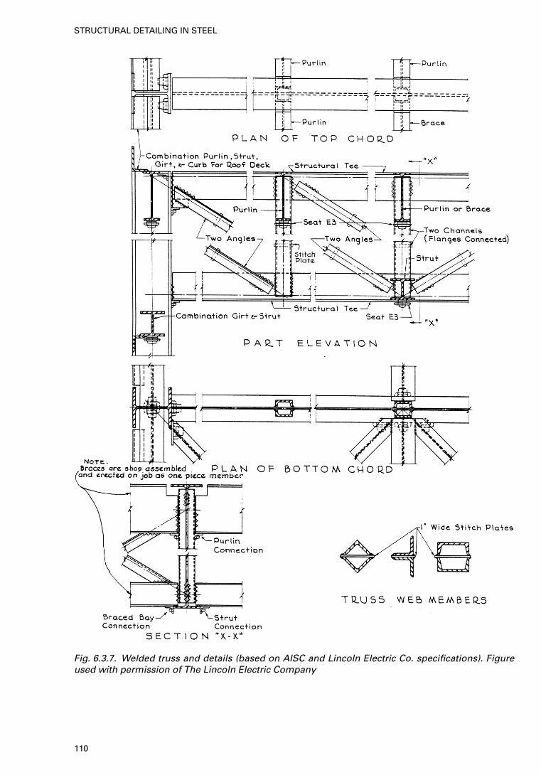
Fig. 6.3.7. Welded truss and details (based on AISC and Lincoln Electric Co. specifications). Figureused with permission of The Lincoln Electric Company
110
STRUCTURAL DETAILING IN STEEL
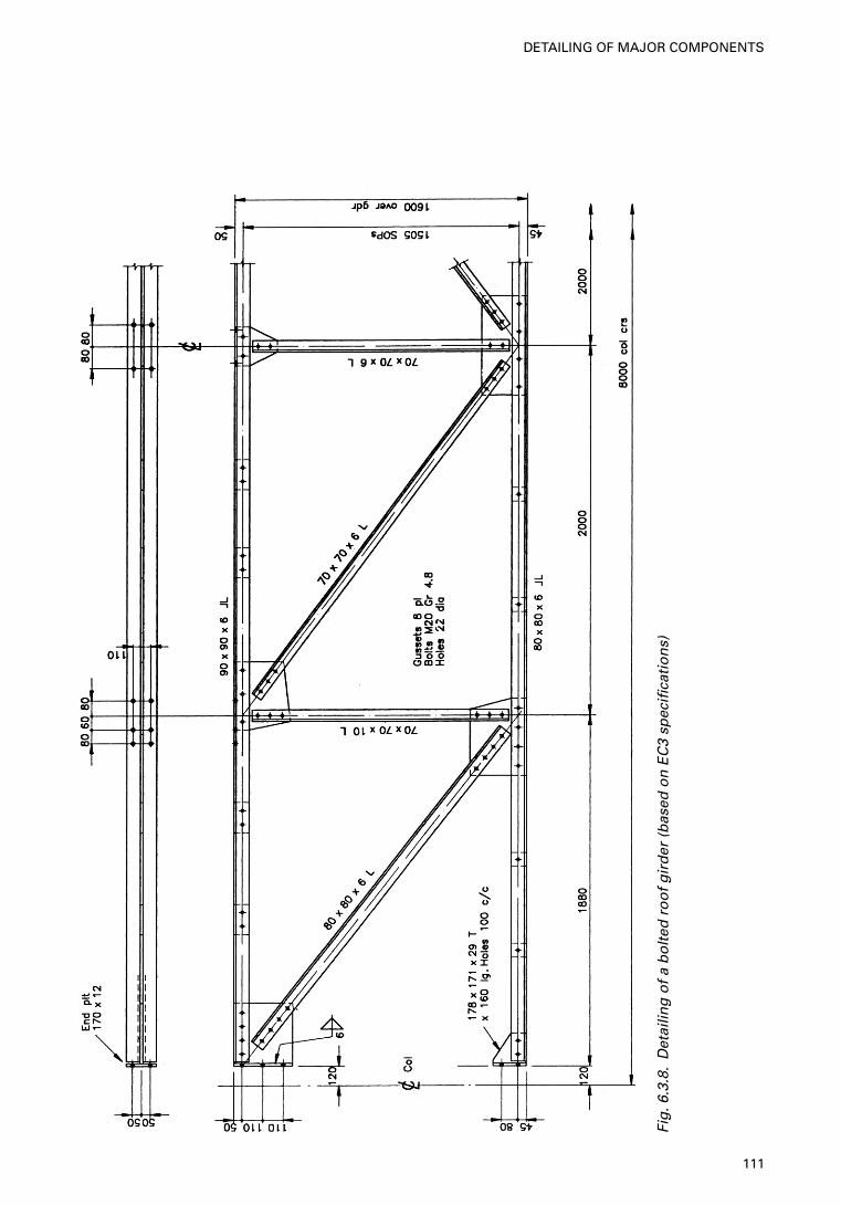
Fig
.6.3
.8.
Det
ailin
g o
f a
bo
lted
ro
of
gir
der
(b
ased
on
EC
3 sp
ecifi
cati
on
s)
111
DETAILING OF MAJOR COMPONENTS
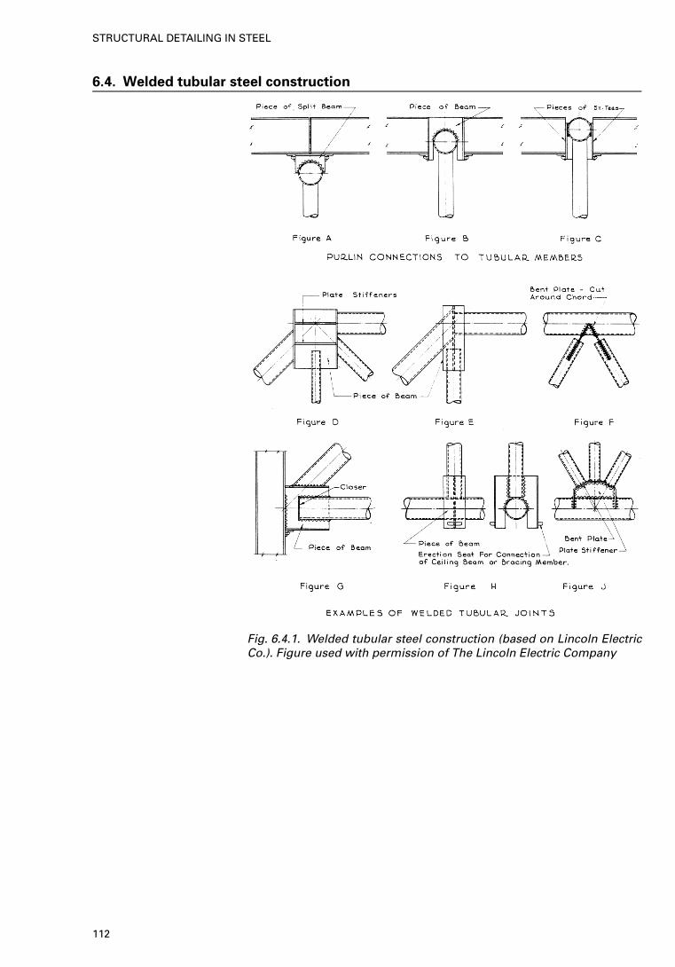
6.4. Welded tubular steel construction
Fig. 6.4.1. Welded tubular steel construction (based on Lincoln ElectricCo.). Figure used with permission of The Lincoln Electric Company
112
STRUCTURAL DETAILING IN STEEL
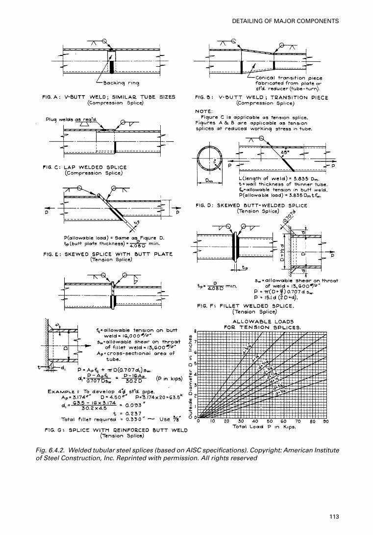
Fig. 6.4.2. Welded tubular steel splices (based on AISC specifications). Copyright: American Instituteof Steel Construction, Inc. Reprinted with permission. All rights reserved
113
DETAILING OF MAJOR COMPONENTS
7. Steel buildings—case studies
Every effort has been made to conform to the recommendations made by theBritish and European (EC3) codes. The figures within this chapter are labelledin accordance with BS 5950. To convert to EC3 recommendations only thesteel grades need to be altered.
115
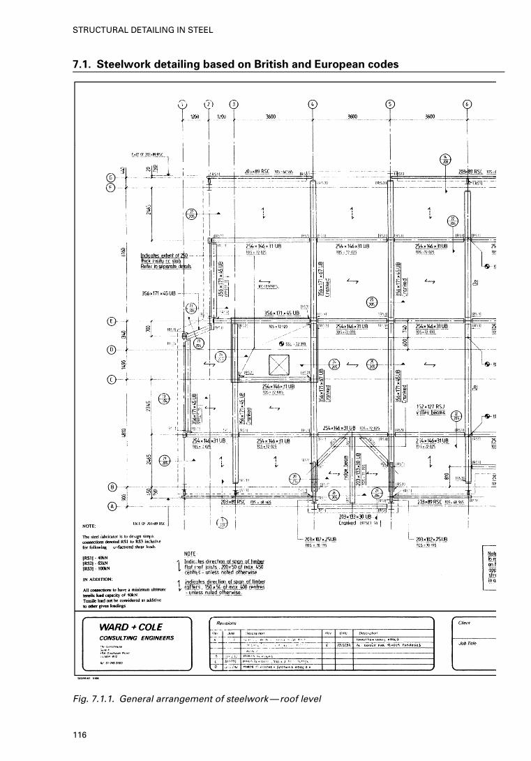
7.1. Steelwork detailing based on British and European codes
Fig. 7.1.1. General arrangement of steelwork—roof level
116
STRUCTURAL DETAILING IN STEEL
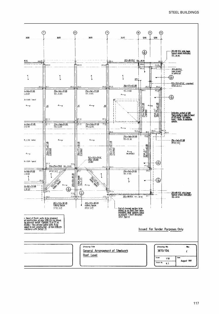
117
STEEL BUILDINGS
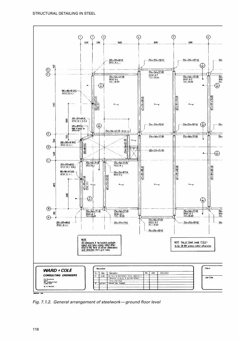
Fig. 7.1.2. General arrangement of steelwork—ground floor level
118
STRUCTURAL DETAILING IN STEEL
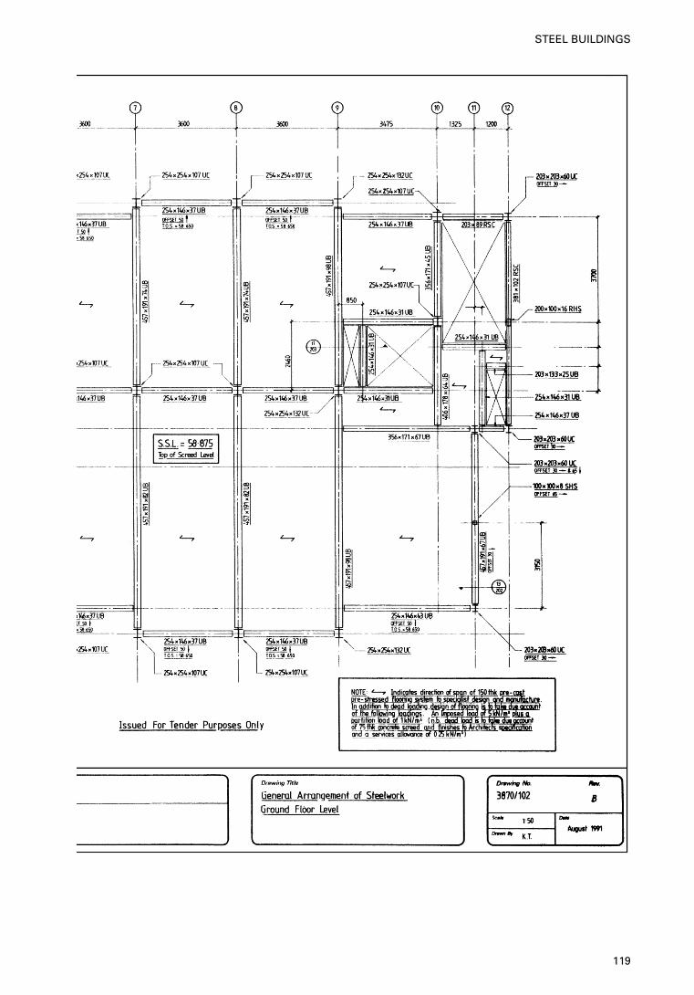
119
STEEL BUILDINGS
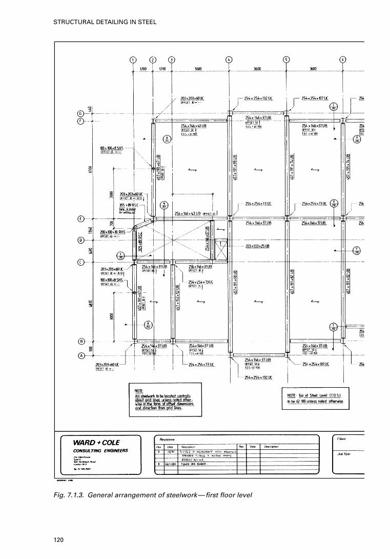
Fig. 7.1.3. General arrangement of steelwork—first floor level
120
STRUCTURAL DETAILING IN STEEL
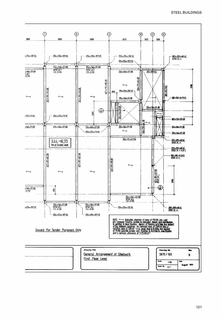
121
STEEL BUILDINGS
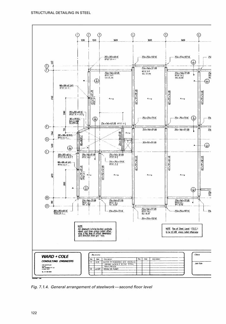
Fig. 7.1.4. General arrangement of steelwork—second floor level
122
STRUCTURAL DETAILING IN STEEL
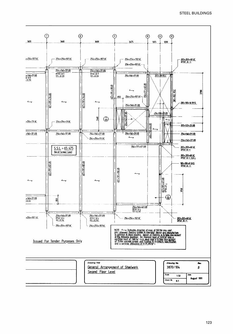
123
STEEL BUILDINGS
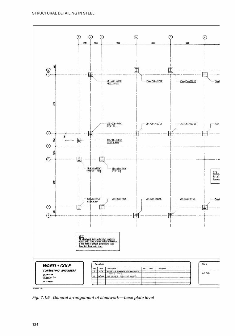
Fig. 7.1.5. General arrangement of steelwork—base plate level
124
STRUCTURAL DETAILING IN STEEL
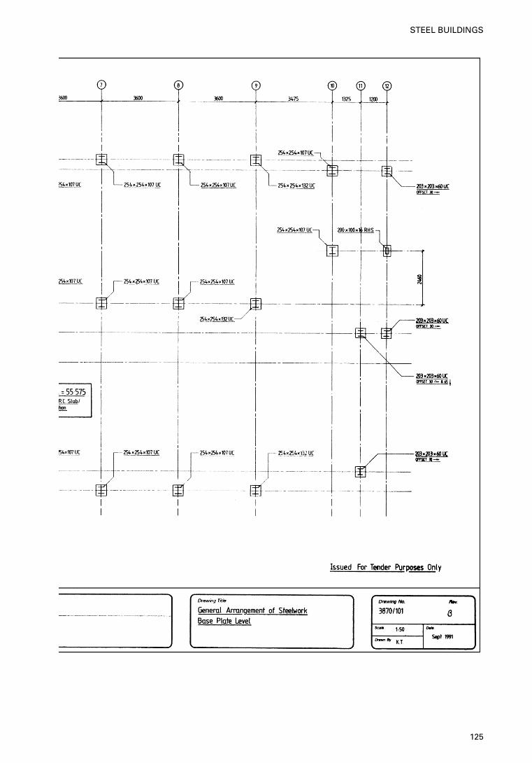
125
STEEL BUILDINGS
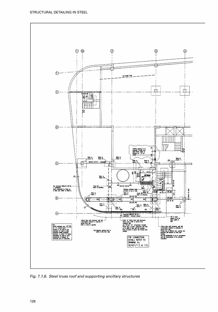
Fig. 7.1.6. Steel truss roof and supporting ancillary structures
126
STRUCTURAL DETAILING IN STEEL
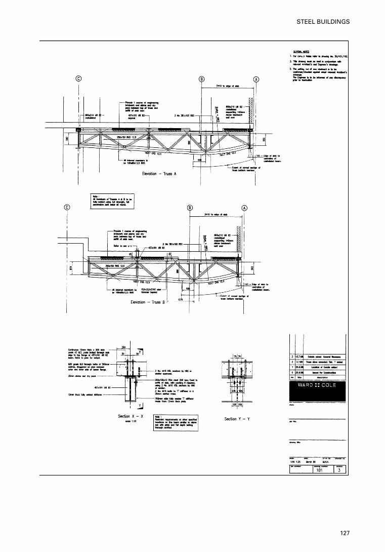
127
STEEL BUILDINGS
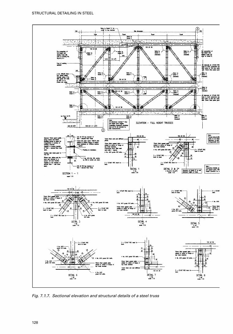
Fig. 7.1.7. Sectional elevation and structural details of a steel truss
128
STRUCTURAL DETAILING IN STEEL
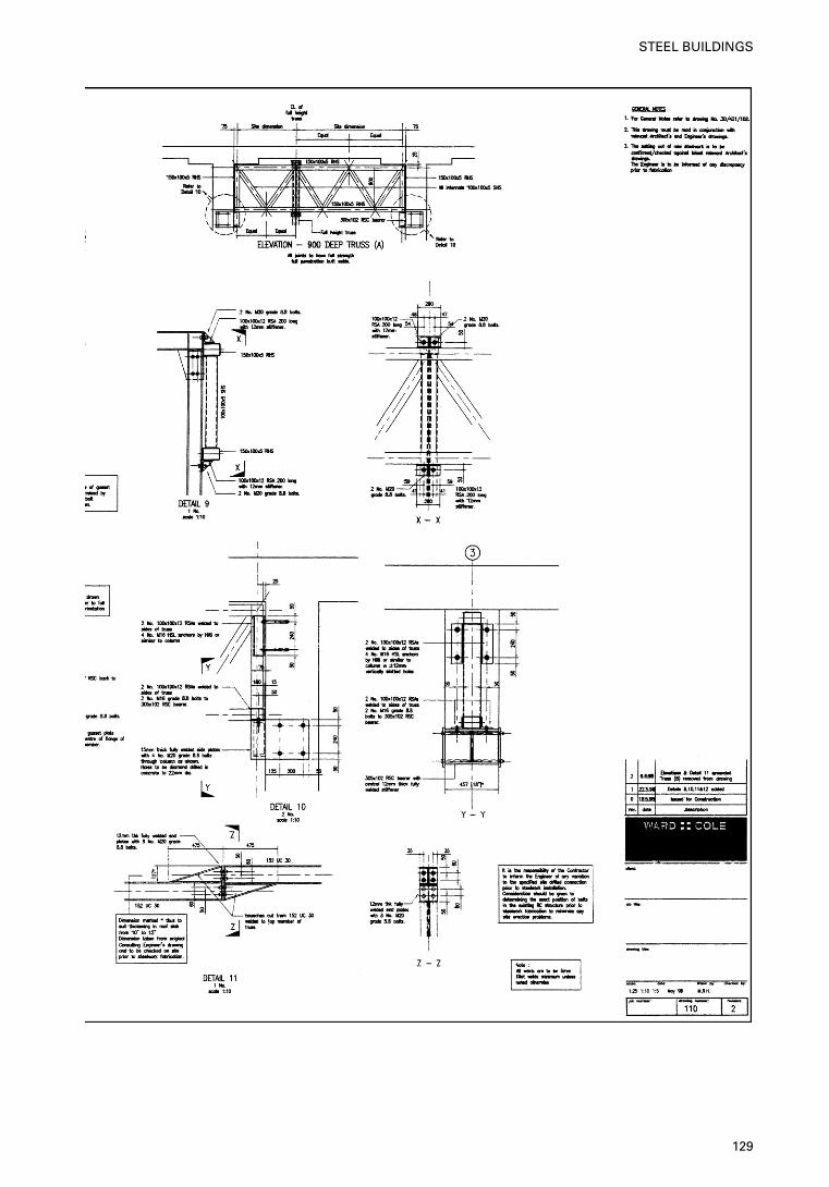
129
STEEL BUILDINGS
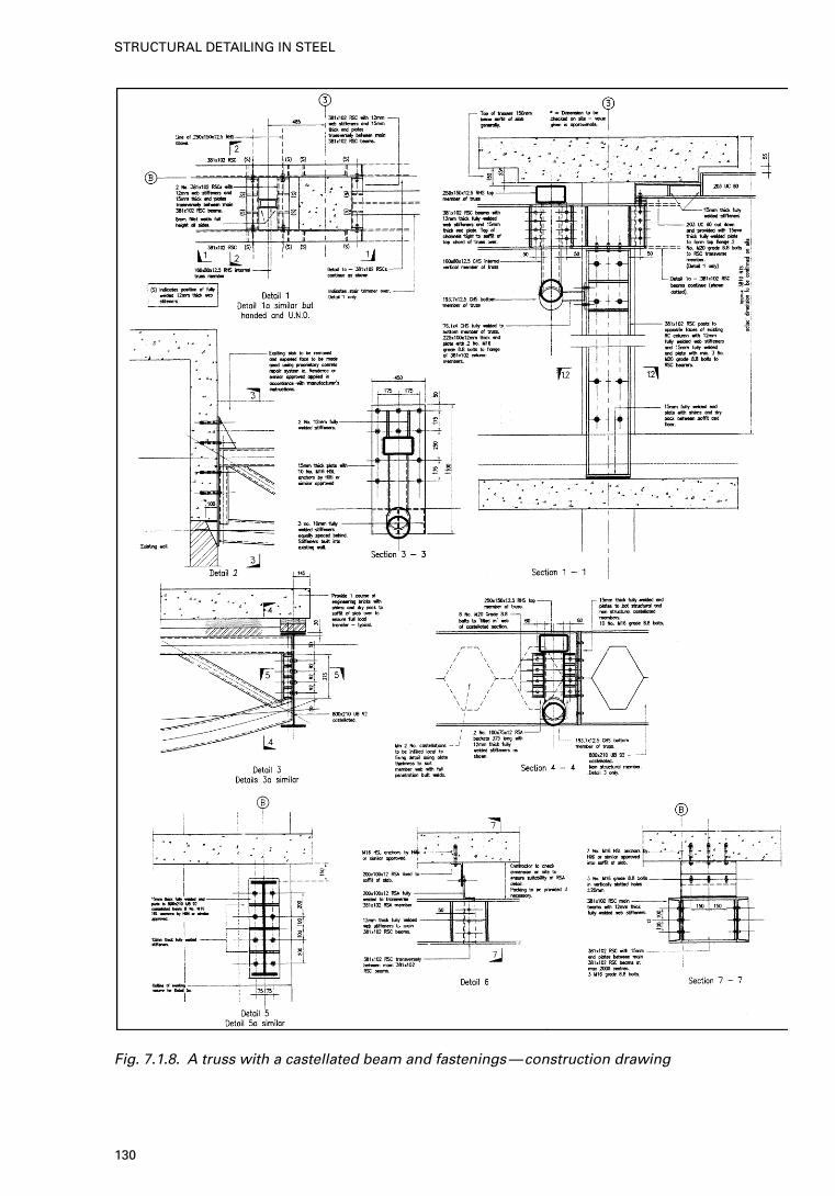
Fig. 7.1.8. A truss with a castellated beam and fastenings—construction drawing
130
STRUCTURAL DETAILING IN STEEL
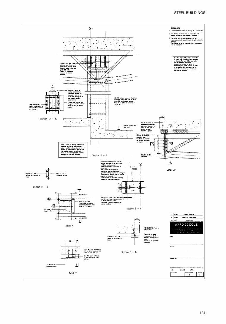
131
STEEL BUILDINGS
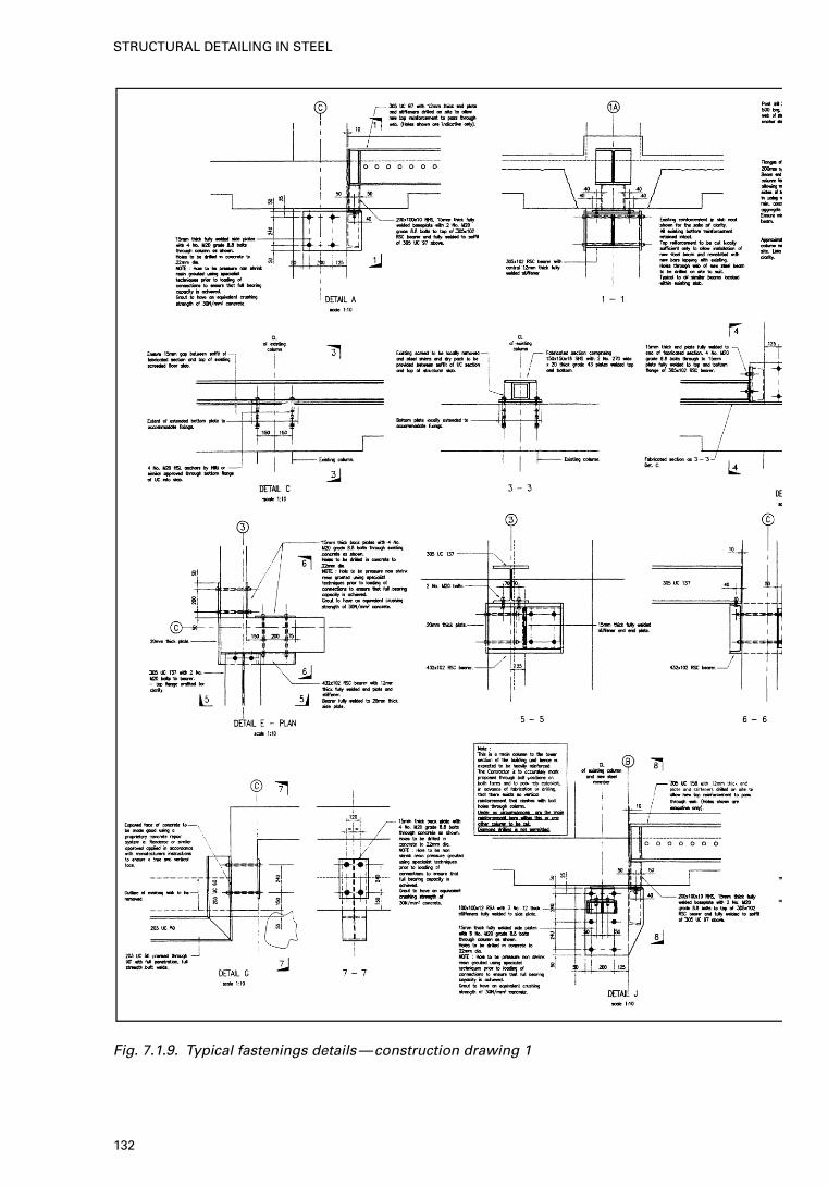
Fig. 7.1.9. Typical fastenings details—construction drawing 1
132
STRUCTURAL DETAILING IN STEEL
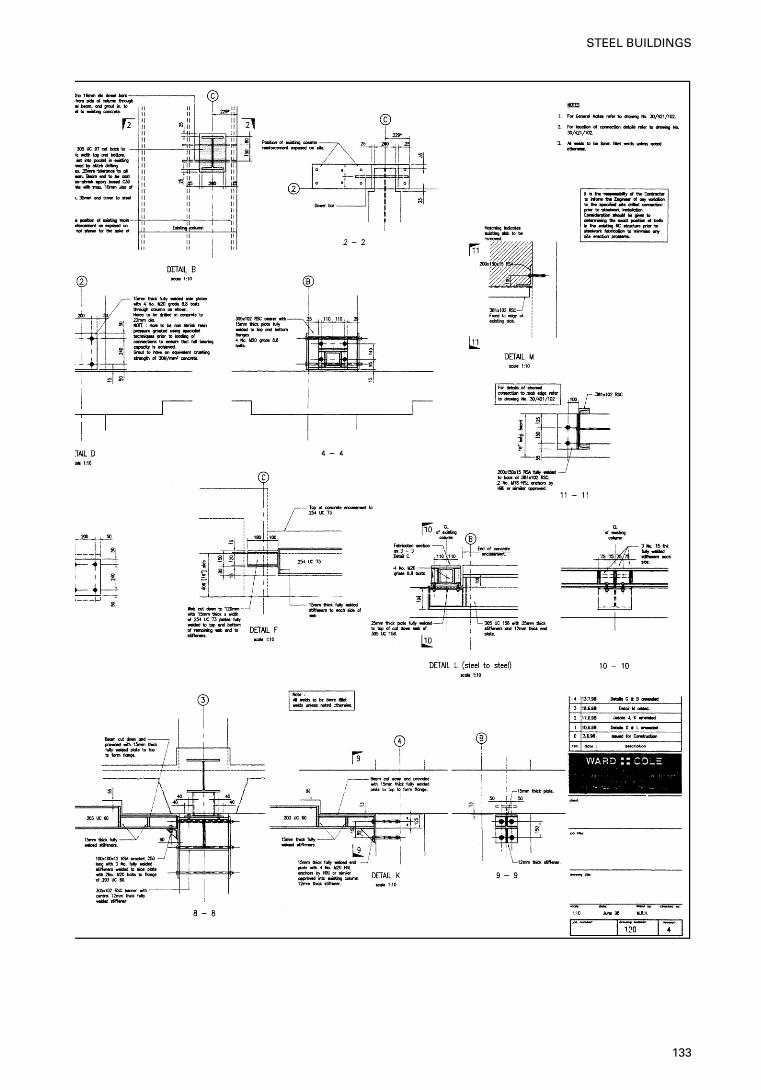
133
STEEL BUILDINGS
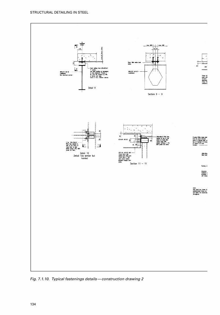
Fig. 7.1.10. Typical fastenings details—construction drawing 2
134
STRUCTURAL DETAILING IN STEEL
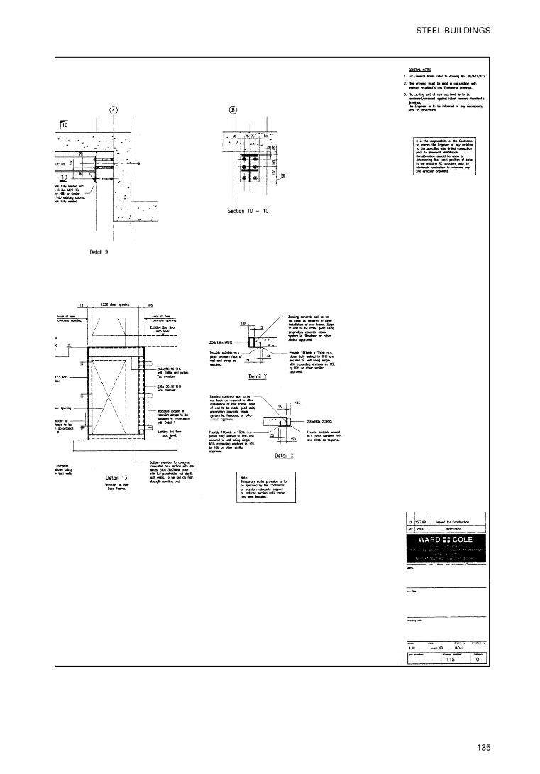
135
STEEL BUILDINGS
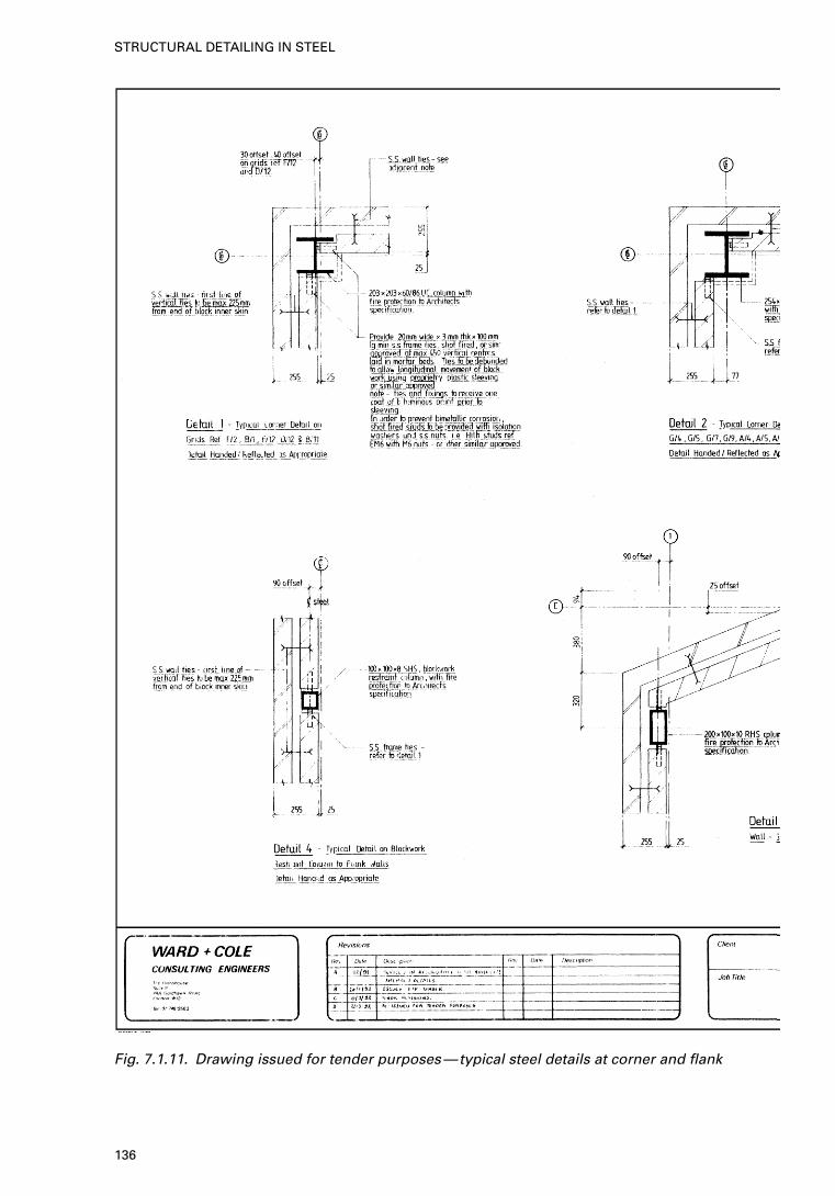
Fig. 7.1.11. Drawing issued for tender purposes—typical steel details at corner and flank
136
STRUCTURAL DETAILING IN STEEL
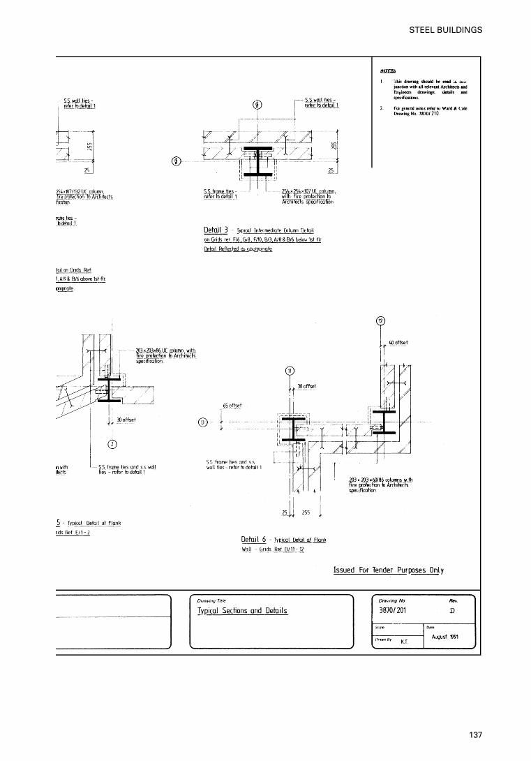
137
STEEL BUILDINGS
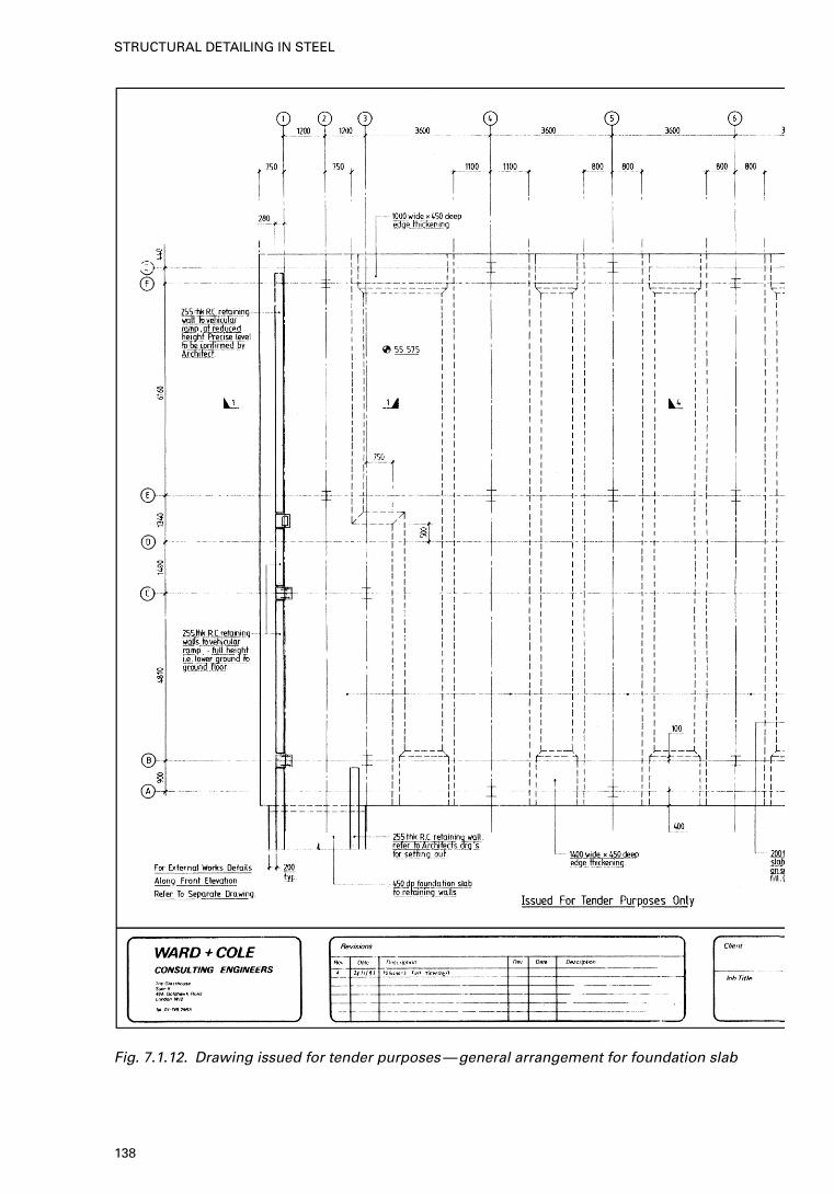
Fig. 7.1.12. Drawing issued for tender purposes—general arrangement for foundation slab
138
STRUCTURAL DETAILING IN STEEL
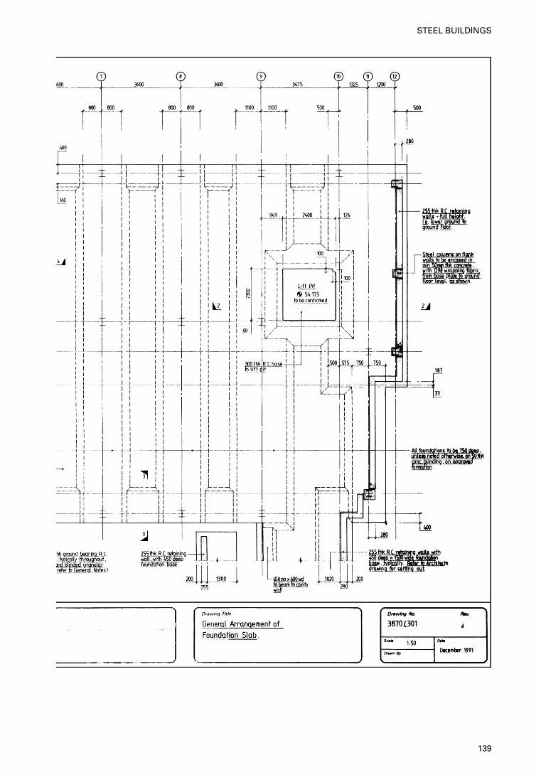
139
STEEL BUILDINGS
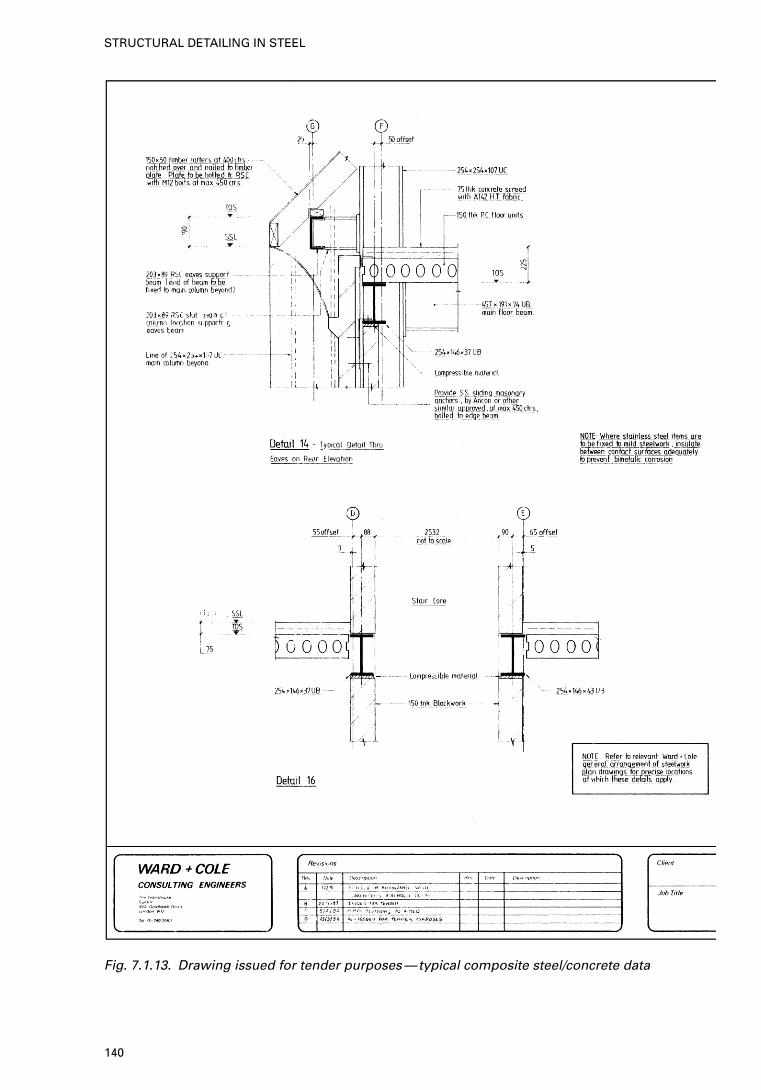
Fig. 7.1.13. Drawing issued for tender purposes—typical composite steel/concrete data
140
STRUCTURAL DETAILING IN STEEL
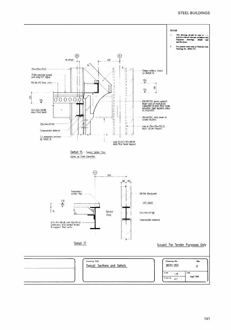
141
STEEL BUILDINGS
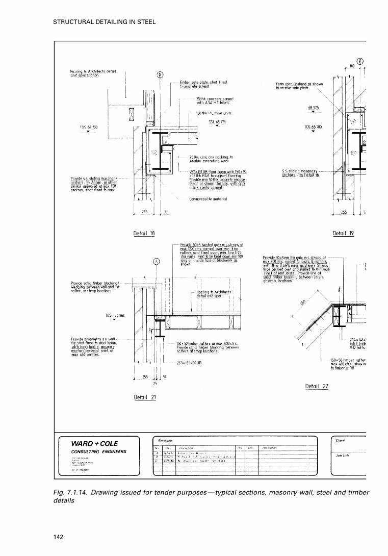
Fig. 7.1.14. Drawing issued for tender purposes—typical sections, masonry wall, steel and timberdetails
142
STRUCTURAL DETAILING IN STEEL
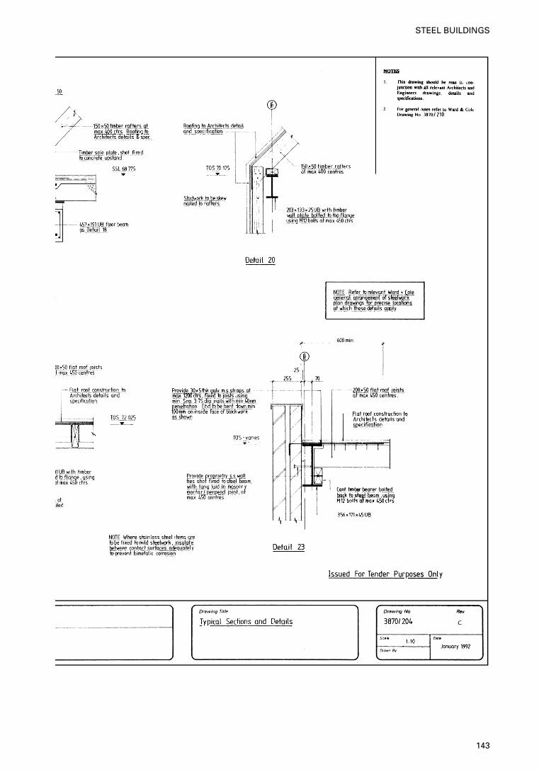
143
STEEL BUILDINGS
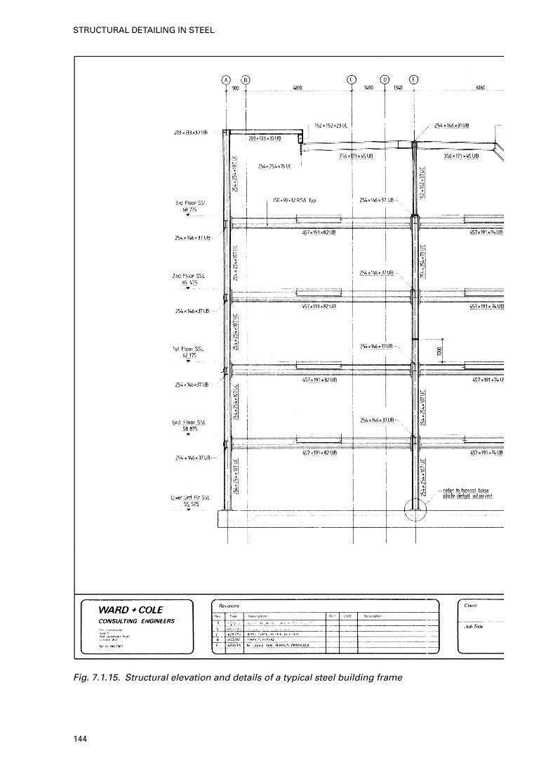
Fig. 7.1.15. Structural elevation and details of a typical steel building frame
144
STRUCTURAL DETAILING IN STEEL
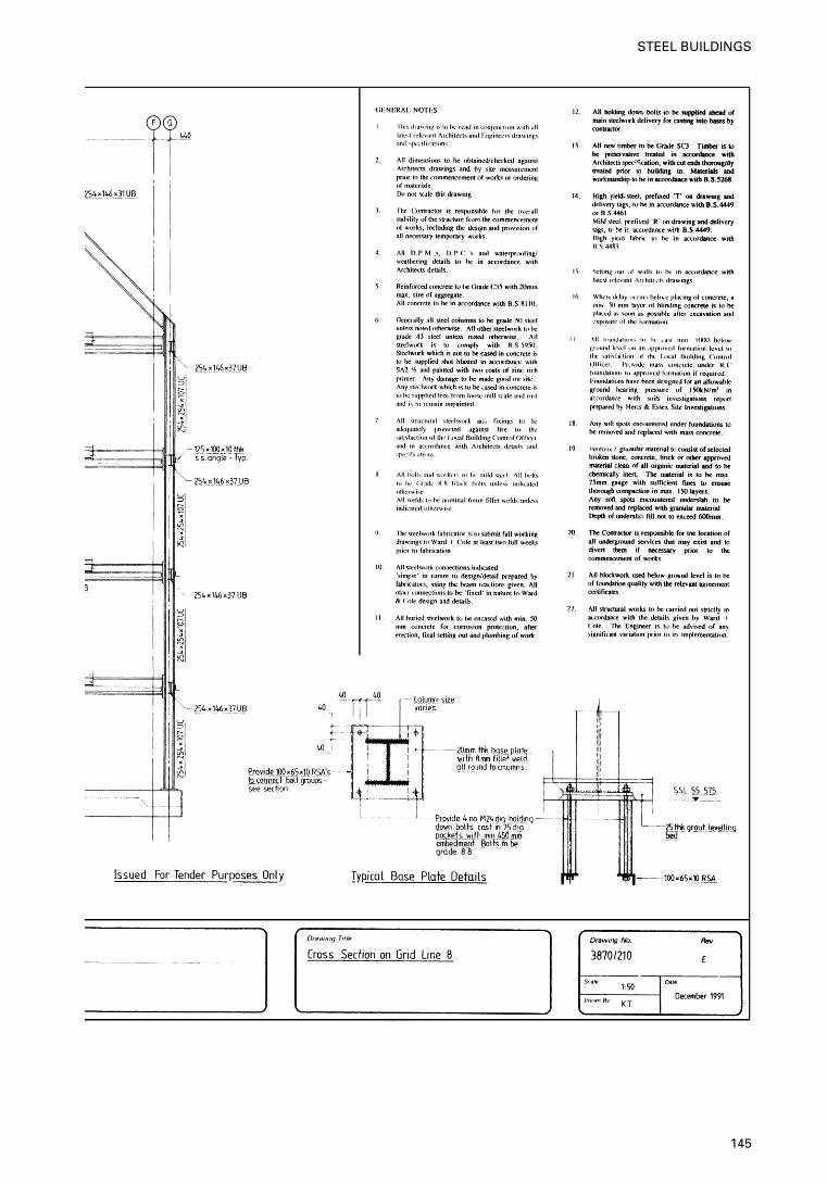
145
STEEL BUILDINGS
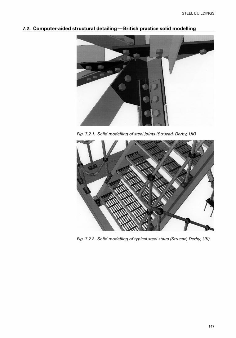
7.2. Computer-aided structural detailing—British practice solid modelling
Fig. 7.2.1. Solid modelling of steel joints (Strucad, Derby, UK)
Fig. 7.2.2. Solid modelling of typical steel stairs (Strucad, Derby, UK)
147
STEEL BUILDINGS
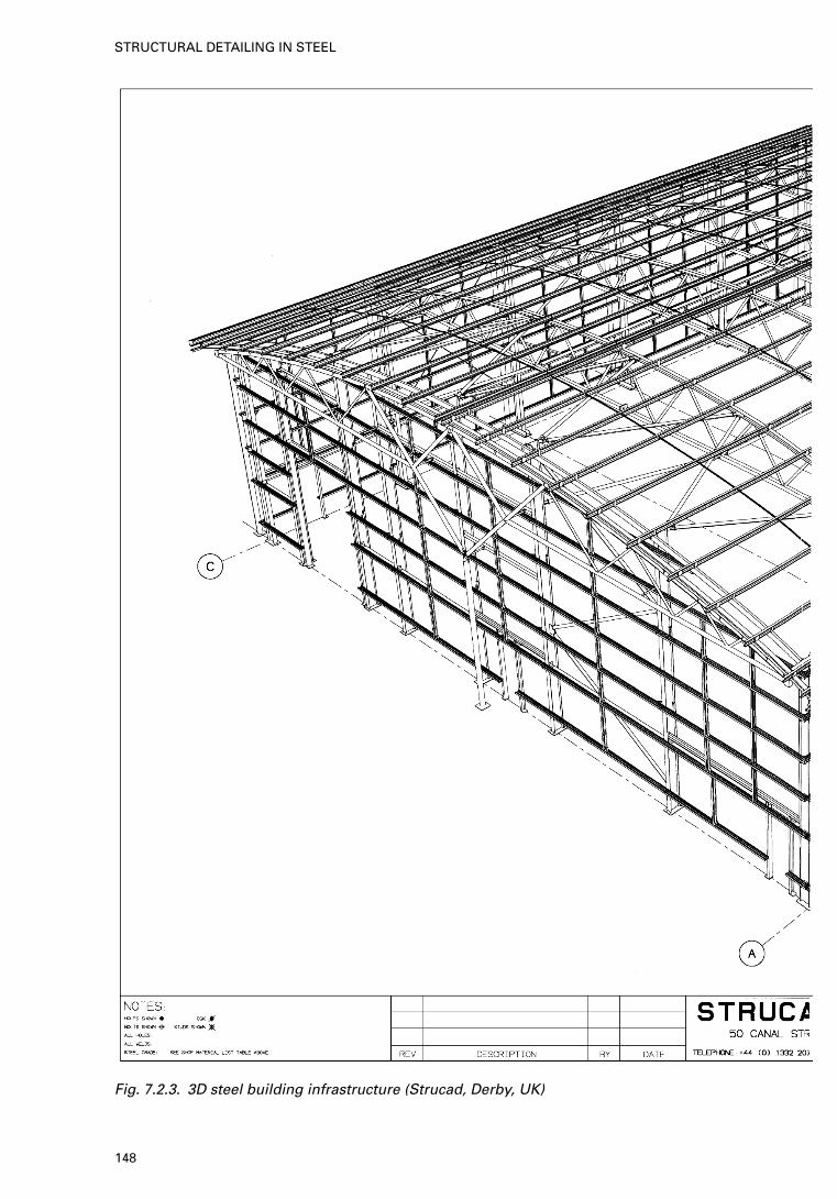
Fig. 7.2.3. 3D steel building infrastructure (Strucad, Derby, UK)
148
STRUCTURAL DETAILING IN STEEL
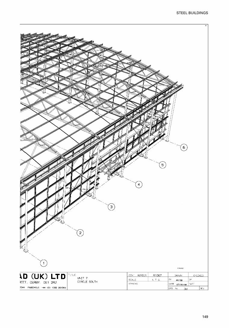
149
STEEL BUILDINGS
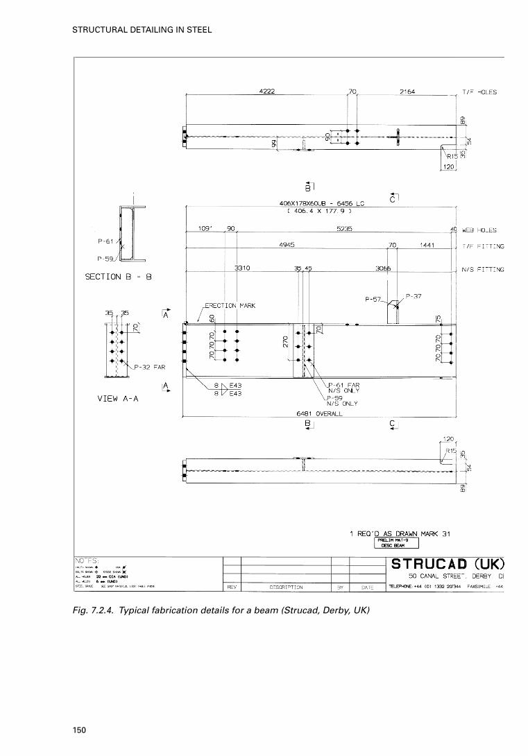
Fig. 7.2.4. Typical fabrication details for a beam (Strucad, Derby, UK)
150
STRUCTURAL DETAILING IN STEEL
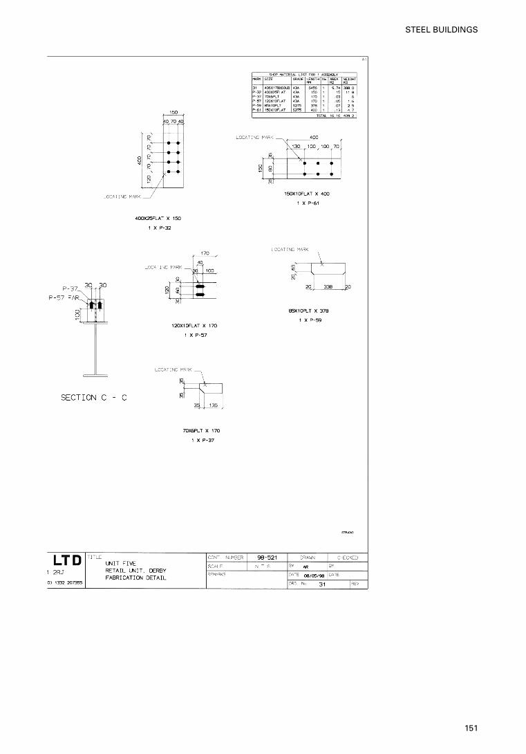
151
STEEL BUILDINGS
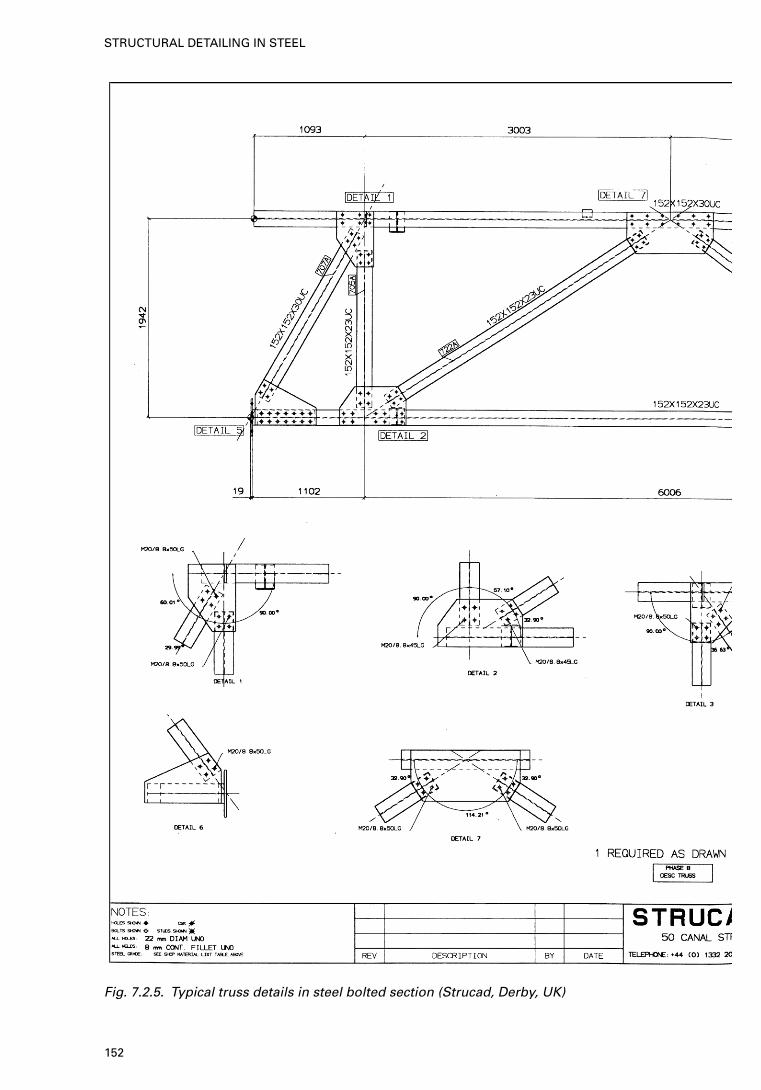
Fig. 7.2.5. Typical truss details in steel bolted section (Strucad, Derby, UK)
152
STRUCTURAL DETAILING IN STEEL
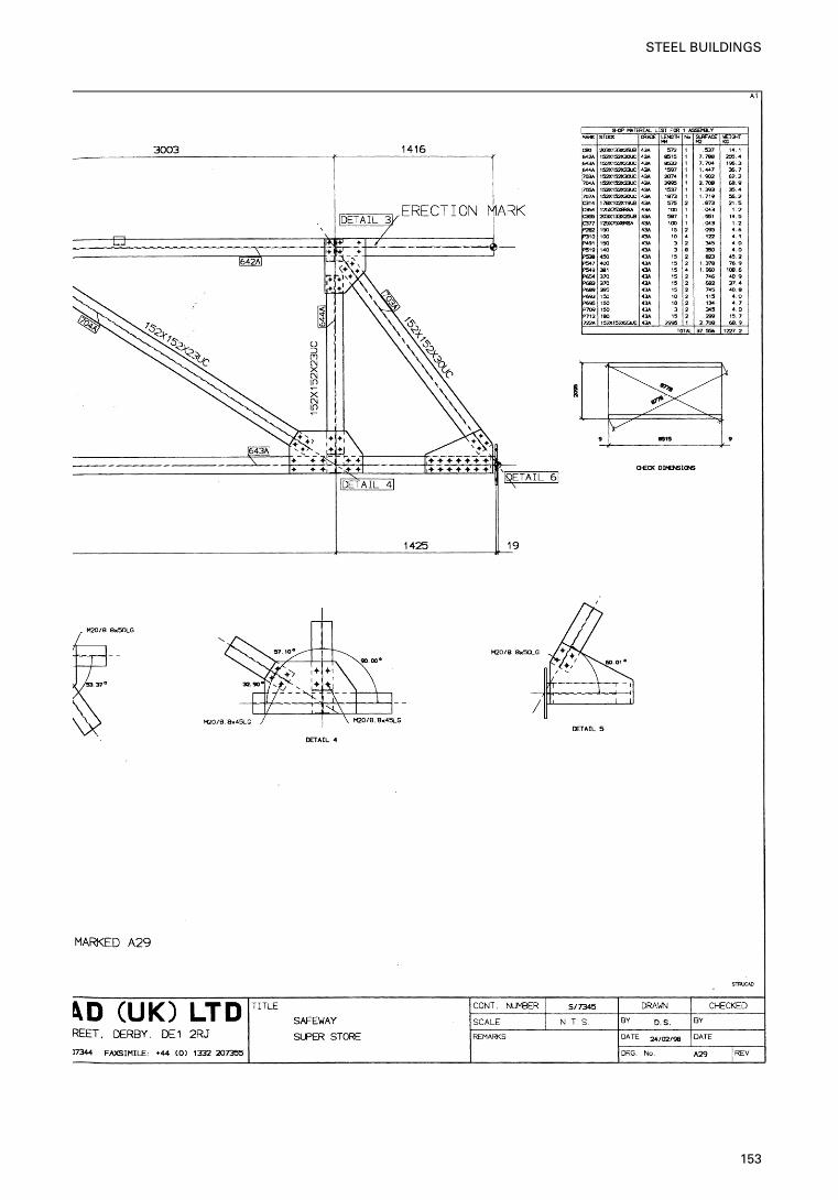
153
STEEL BUILDINGS
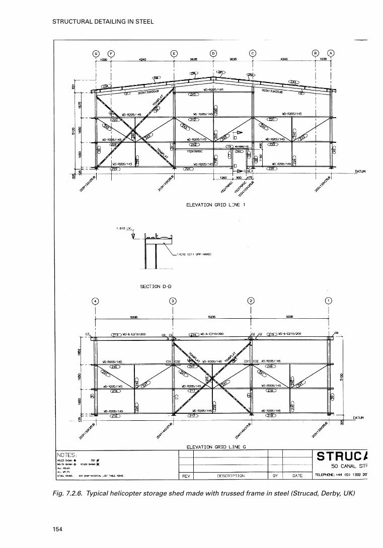
Fig. 7.2.6. Typical helicopter storage shed made with trussed frame in steel (Strucad, Derby, UK)
154
STRUCTURAL DETAILING IN STEEL
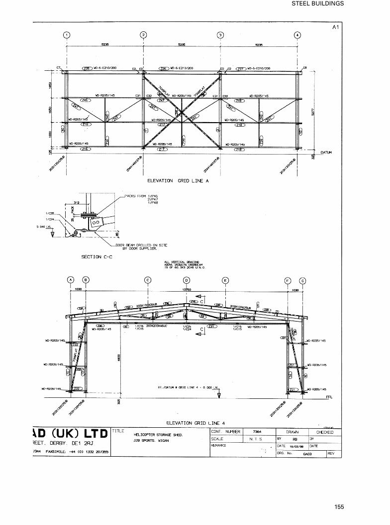
155
STEEL BUILDINGS
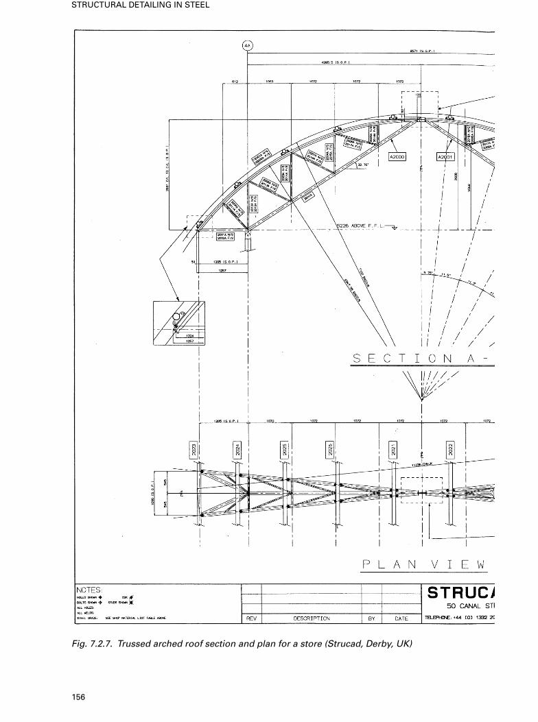
Fig. 7.2.7. Trussed arched roof section and plan for a store (Strucad, Derby, UK)
156
STRUCTURAL DETAILING IN STEEL
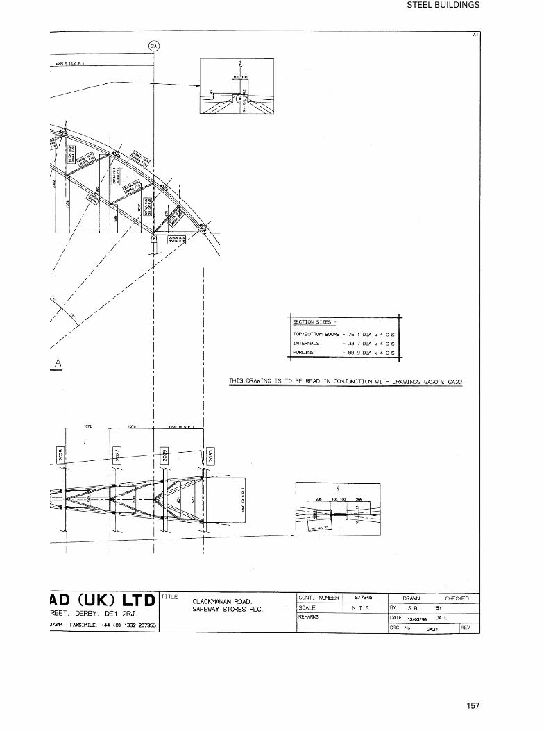
157
STEEL BUILDINGS
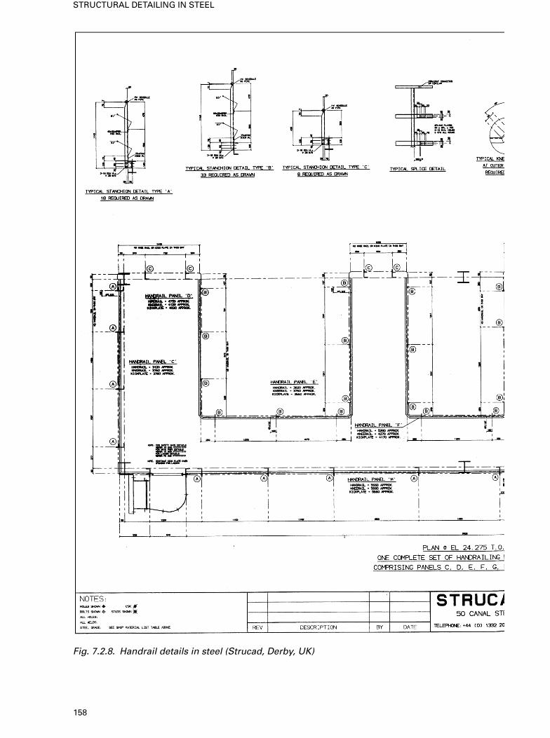
Fig. 7.2.8. Handrail details in steel (Strucad, Derby, UK)
158
STRUCTURAL DETAILING IN STEEL
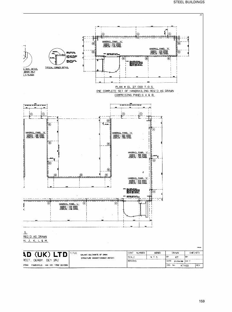
159
STEEL BUILDINGS
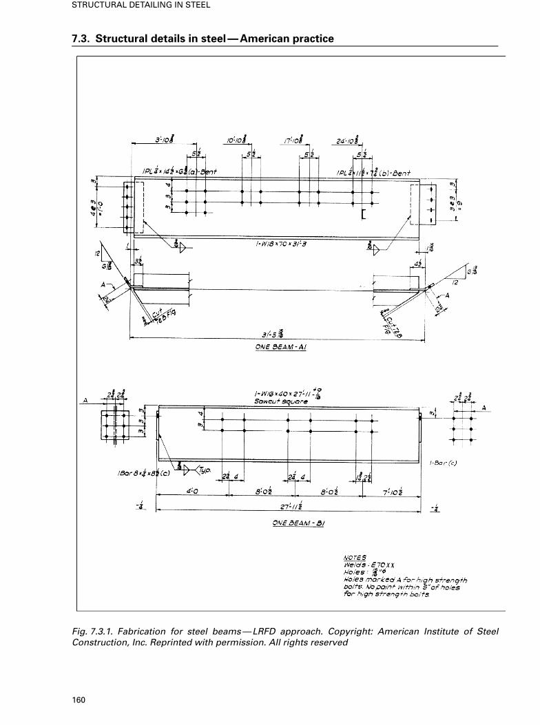
7.3. Structural details in steel—American practice
Fig. 7.3.1. Fabrication for steel beams—LRFD approach. Copyright: American Institute of SteelConstruction, Inc. Reprinted with permission. All rights reserved
160
STRUCTURAL DETAILING IN STEEL
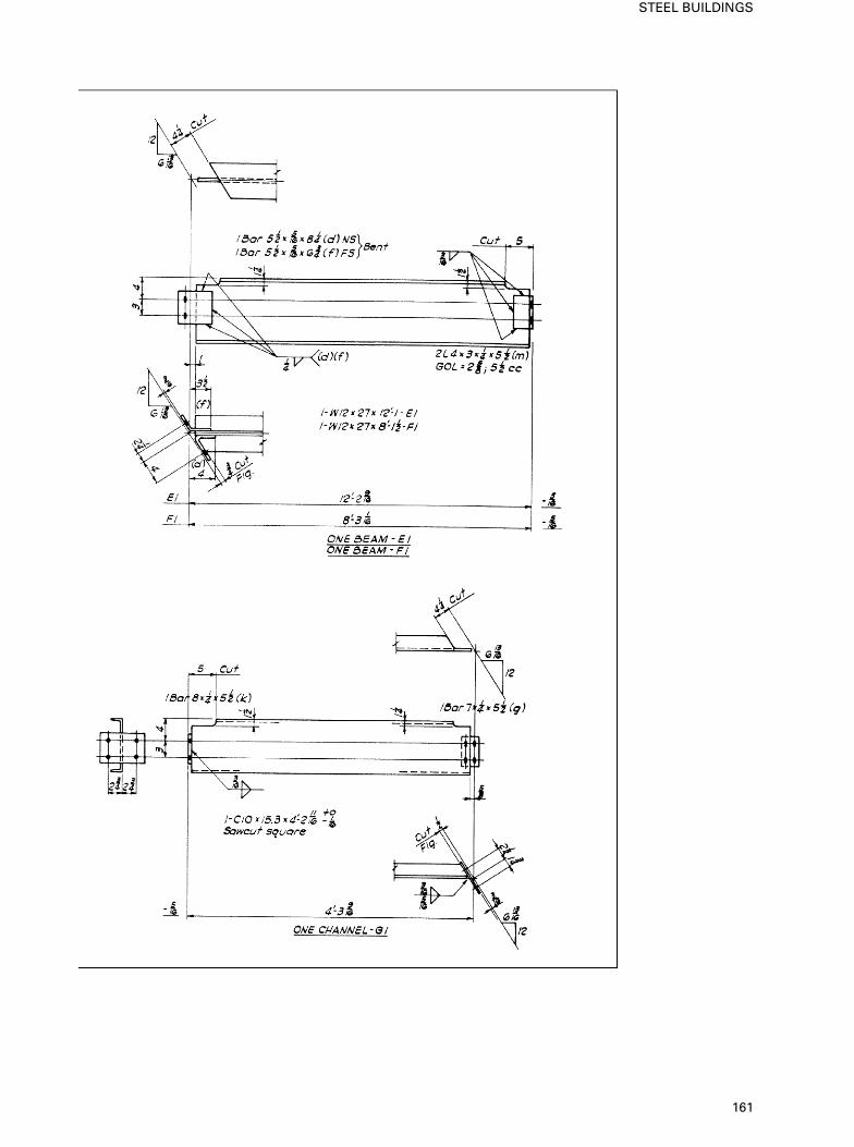
161
STEEL BUILDINGS
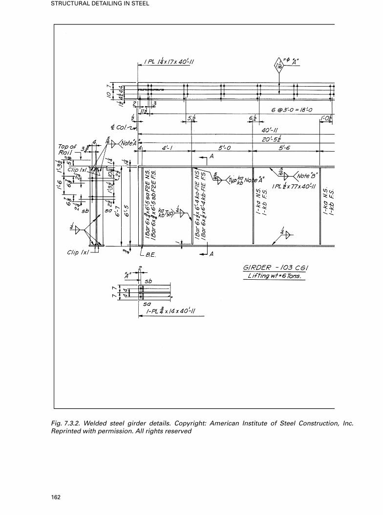
Fig. 7.3.2. Welded steel girder details. Copyright: American Institute of Steel Construction, Inc.Reprinted with permission. All rights reserved
162
STRUCTURAL DETAILING IN STEEL
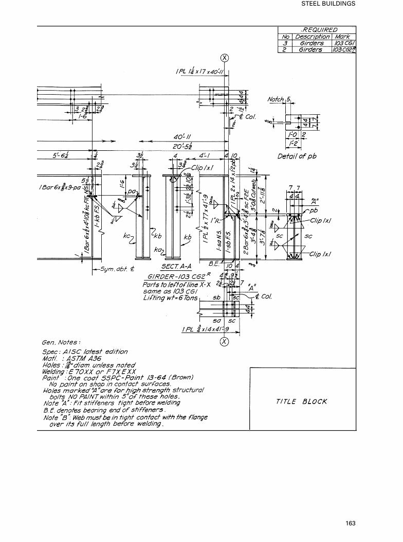
163
STEEL BUILDINGS
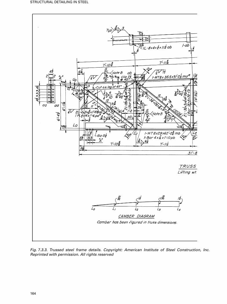
Fig. 7.3.3. Trussed steel frame details. Copyright: American Institute of Steel Construction, Inc.Reprinted with permission. All rights reserved
164
STRUCTURAL DETAILING IN STEEL
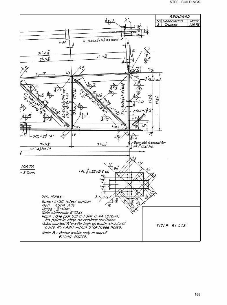
165
STEEL BUILDINGS
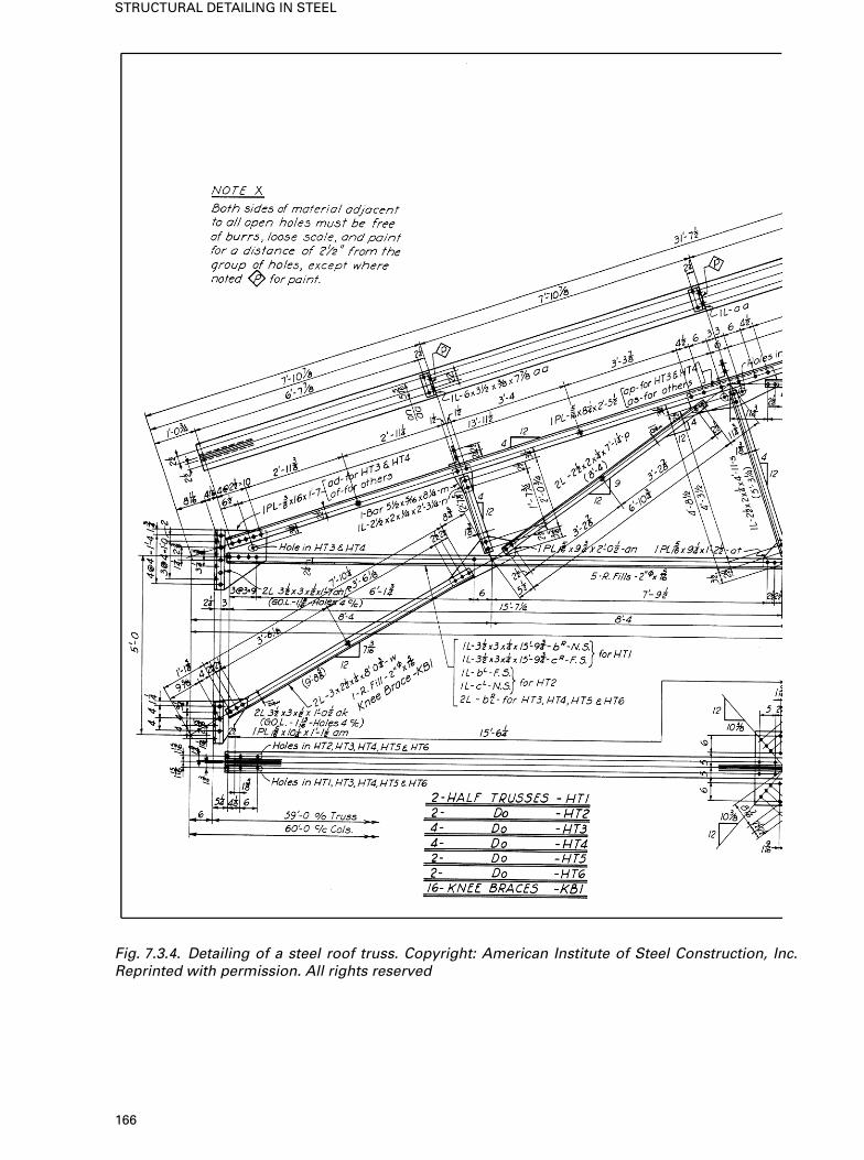
Fig. 7.3.4. Detailing of a steel roof truss. Copyright: American Institute of Steel Construction, Inc.Reprinted with permission. All rights reserved
166
STRUCTURAL DETAILING IN STEEL
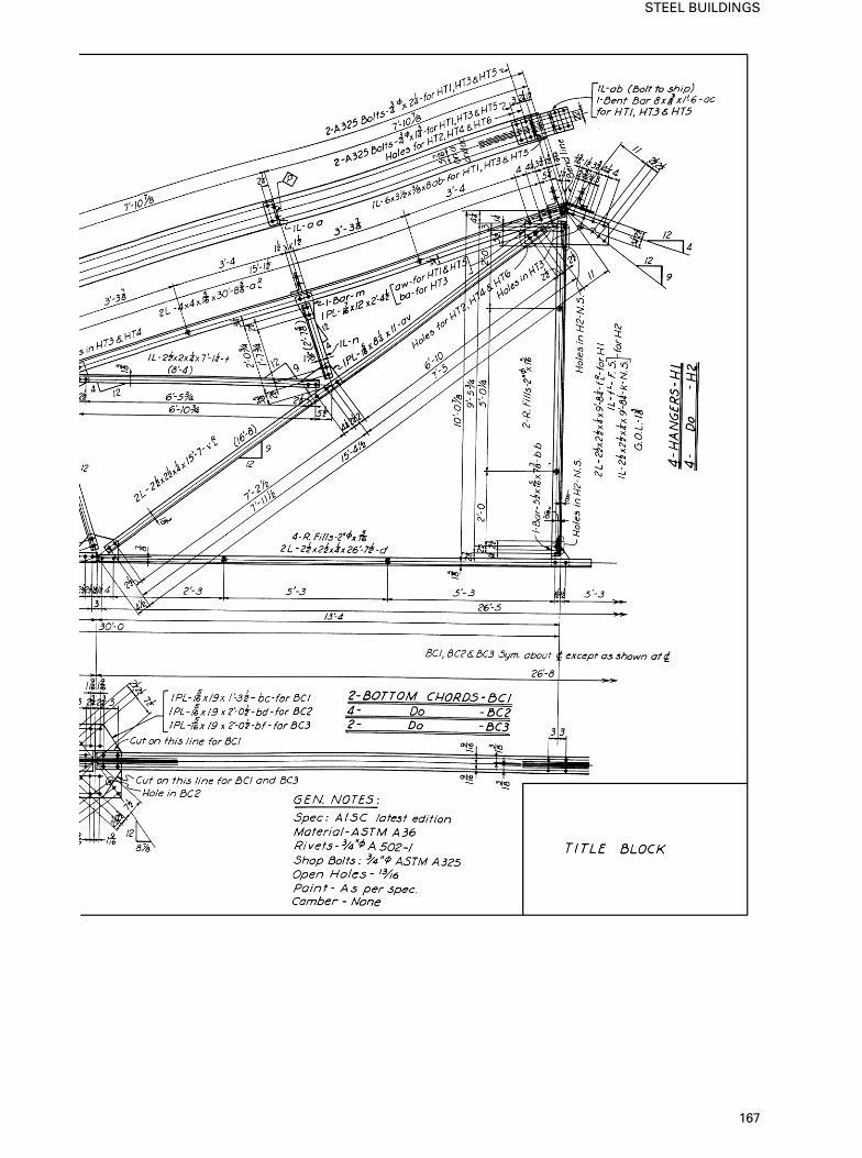
167
STEEL BUILDINGS
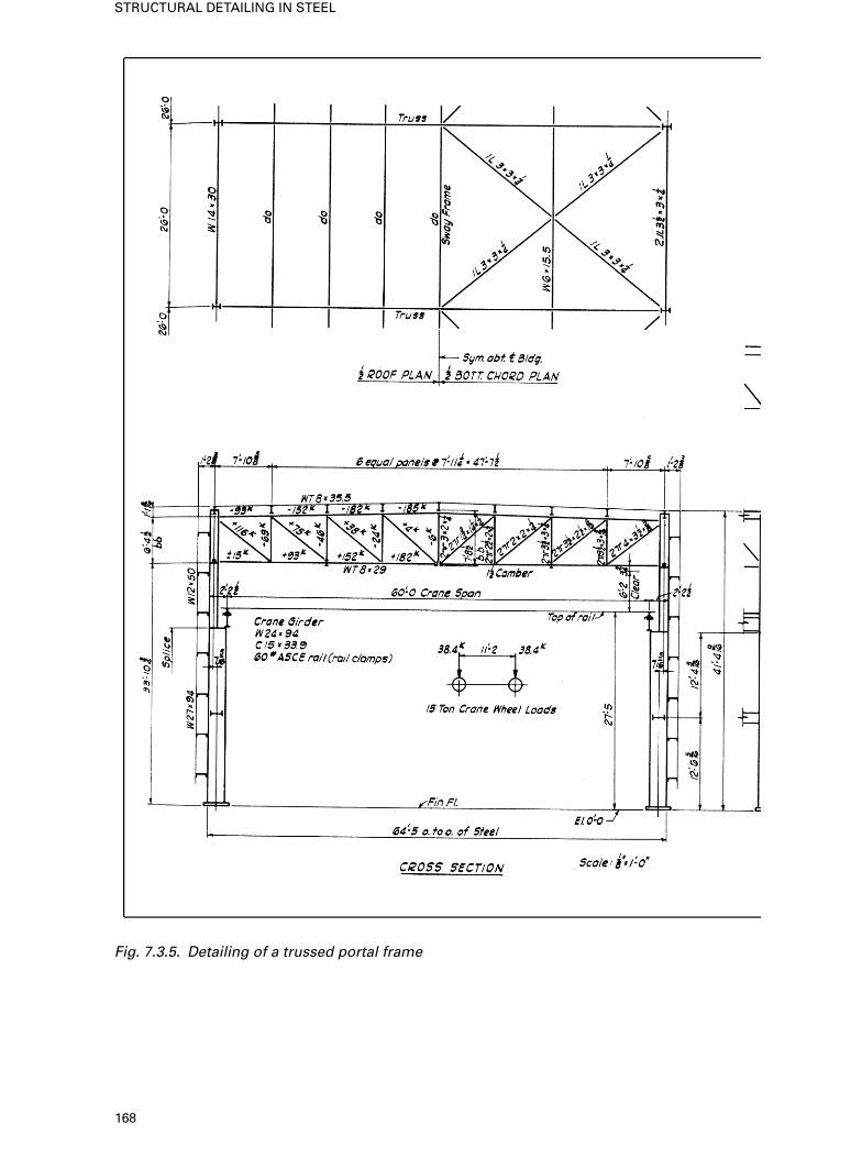
Fig. 7.3.5. Detailing of a trussed portal frame
168
STRUCTURAL DETAILING IN STEEL
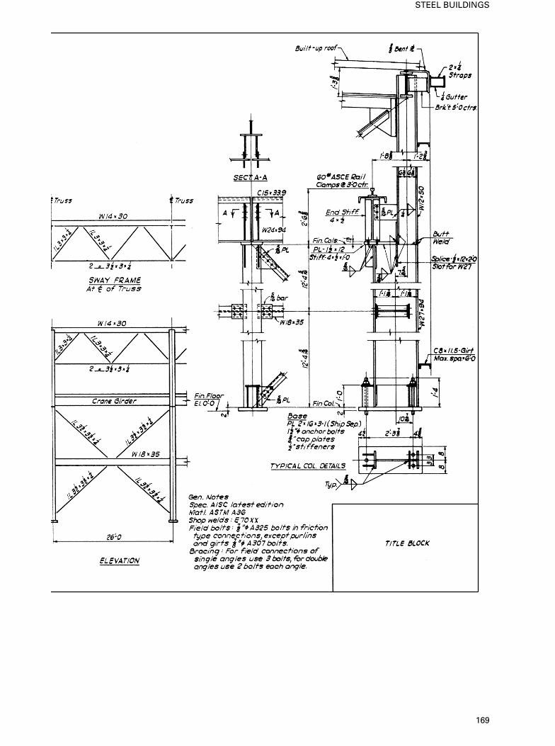
169
STEEL BUILDINGS
8. Steel bridges—case studies
This chapter contains the relevant specifications of the British, European andAmerican codes on the design/detailing of steel bridges and their importantcomponents. In some cases the practices are self-explanatory and need noadditional text to clarify them. For thorough explanations of theory, designanalysis and structural detailing refer to Prototype bridge structures: analysisand design by the author, published by Thomas Telford, London, 1999.
8.1. Bridge loadings and specifications
8.1.1. Highway bridge
live loads based on
British practice
General Standard highway loading consists of HA and HB loading. HAloading is a formula loading representing normal traffic in Great Britain. HBloading is an abnormal vehicle unit loading. Both loadings include impact.
Loads to be considered The structure and its elements shall be designed toresist the more severe effects of either:
• design HA loading (see Fig. 8.1)• design HA loading combined with design HB loading.
Notional lanes, hard shoulders, etc. The width and number of notional lanes,and the presence of hard shoulders, hard strips, verges and central reserves areintegral to the disposition of HA and HB loading. Requirements for derivingthe width and number of notional lanes for design purposes are specified in8.1.2. Requirements for reducing HA loading for certain lane widths andloaded length are specified.
Distribution analysis of structure The effects of the design standard loadingsshall, where appropriate, be distributed in accordance with a rigorousdistribution analysis or from data derived from suitable tests. In the latter case,the use of such data shall be subject to the approval of the appropriateauthority.
Type HA loading Type HA loading consists of a uniformly distributed load(see Clause 8.1.2 of the code) and a knife edge load combined, or of a singlewheel load.
Table 8.1. Factors for limit state for combination of loads (HA type)
Design HA loading – for design HA load considered alone, VFL shall be taken asfollows:
For the ultimate For the serviceabilitylimit state limit state
For combination 1 1.50 1.20For combinations 2 and 3 1.25 1.00
Where HA loading is coexisting with HB loading (see Clause 6.4.2) VFL, as specified in Clause6.3.4, shall be applied to HA loading (BS 5950).
170
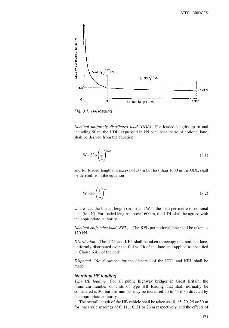
Nominal uniformly distributed load (UDL) For loaded lengths up to andincluding 50 m, the UDL, expressed in kN per linear metre of notional lane,shall be derived from the equation
W=336�1
L�0·67
(8.1)
and for loaded lengths in excess of 50 m but less than 1600 m the UDL shallbe derived from the equation
W=36�1
L�0·1
(8.2)
where L is the loaded length (in m) and W is the load per metre of notionallane (in kN). For loaded lengths above 1600 m, the UDL shall be agreed withthe appropriate authority.
Nominal knife edge load (KEL) The KEL per notional lane shall be taken as120 kN.
Distribution The UDL and KEL shall be taken to occupy one notional lane,uniformly distributed over the full width of the lane and applied as specifiedin Clause 6.4.1 of the code.
Dispersal No allowance for the dispersal of the UDL and KEL shall bemade.
Nominal HB loadingType HB loading For all public highway bridges in Great Britain, theminimum number of units of type HB loading that shall normally beconsidered is 30, but this number may be increased up to 45 if so directed bythe appropriate authority.
The overall length of the HB vehicle shall be taken as 10, 15, 20, 25 or 30 mfor inner axle spacings of 6, 11, 16, 21 or 26 m respectively, and the effects of
Fig. 8.1. HA loading
171
STEEL BRIDGES
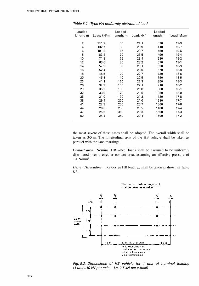
the most severe of these cases shall be adopted. The overall width shall betaken as 3·5 m. The longitudinal axis of the HB vehicle shall be taken asparallel with the lane markings.
Contact area Nominal HB wheel loads shall be assumed to be uniformlydistributed over a circular contact area, assuming an effective pressure of1·1 N/mm2.
Design HB loading For design HB load, yfL shall be taken as shown in Table8.3.
Table 8.2. Type HA uniformly distributed load
Loaded Loaded Loadedlength: m Load: kN/m length: m Load: kN/m length: m Load: kN/m
2 211·2 55 24·1 370 19·94 132·7 60 23·9 410 19·76 101·2 65 23·7 450 19·58 83·4 70 23·5 490 19·4
10 71·8 75 23·4 530 19·212 63·6 80 23·2 570 19·114 57·3 85 23·1 620 18·916 52·4 90 23·0 670 18·818 48·5 100 22·7 730 18·620 45·1 110 22·5 790 18·523 41·1 120 22·3 850 18·326 37·9 130 22·1 910 18·229 35·2 150 21·8 980 18·132 33·0 170 21·5 1050 18·035 31·0 190 21·3 1130 17·838 29·4 220 21·0 1210 17·741 27·9 250 20·7 1300 17·644 26·6 280 20·5 1400 17·447 25·5 310 20·3 1500 17·350 24·4 340 20·1 1600 17·2
Fig. 8.2. Dimensions of HB vehicle for 1 unit of nominal loading(1 unit=10 kN per axle—i.e. 2·5 kN per wheel)
172
STRUCTURAL DETAILING IN STEEL
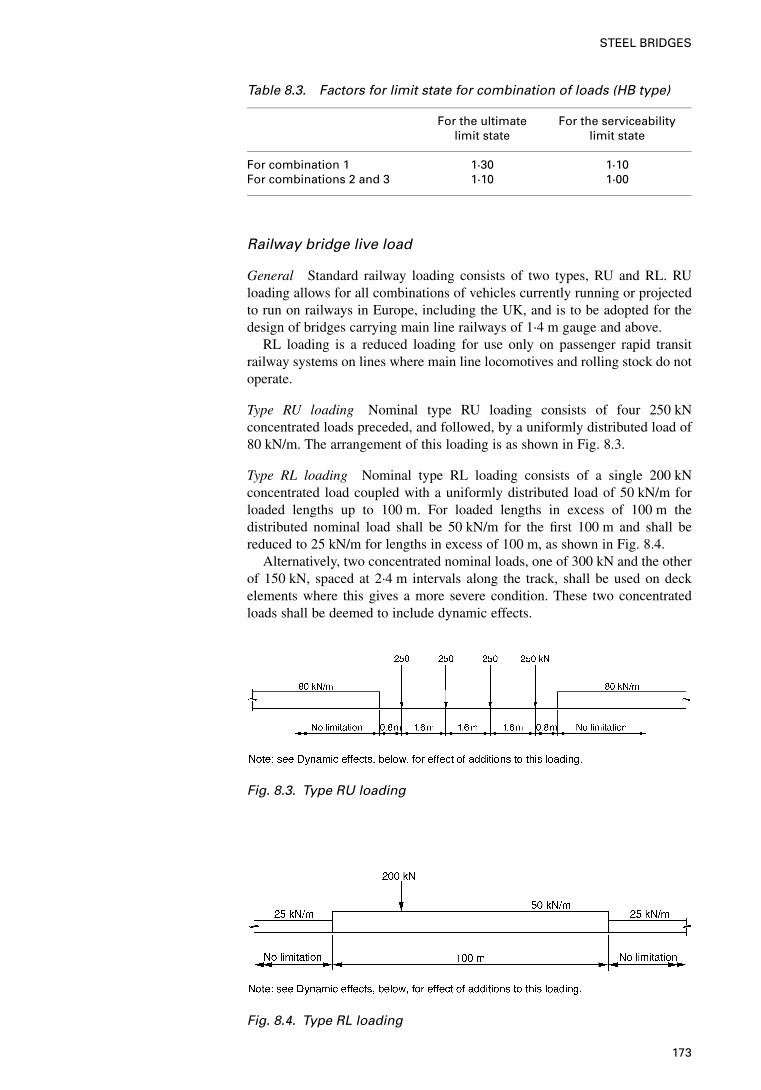
Railway bridge live load
General Standard railway loading consists of two types, RU and RL. RUloading allows for all combinations of vehicles currently running or projectedto run on railways in Europe, including the UK, and is to be adopted for thedesign of bridges carrying main line railways of 1·4 m gauge and above.
RL loading is a reduced loading for use only on passenger rapid transitrailway systems on lines where main line locomotives and rolling stock do notoperate.
Type RU loading Nominal type RU loading consists of four 250 kNconcentrated loads preceded, and followed, by a uniformly distributed load of80 kN/m. The arrangement of this loading is as shown in Fig. 8.3.
Type RL loading Nominal type RL loading consists of a single 200 kNconcentrated load coupled with a uniformly distributed load of 50 kN/m forloaded lengths up to 100 m. For loaded lengths in excess of 100 m thedistributed nominal load shall be 50 kN/m for the first 100 m and shall bereduced to 25 kN/m for lengths in excess of 100 m, as shown in Fig. 8.4.
Alternatively, two concentrated nominal loads, one of 300 kN and the otherof 150 kN, spaced at 2·4 m intervals along the track, shall be used on deckelements where this gives a more severe condition. These two concentratedloads shall be deemed to include dynamic effects.
Table 8.3. Factors for limit state for combination of loads (HB type)
For the ultimate For the serviceabilitylimit state limit state
For combination 1 1·30 1·10For combinations 2 and 3 1·10 1·00
Fig. 8.3. Type RU loading
Fig. 8.4. Type RL loading
173
STEEL BRIDGES
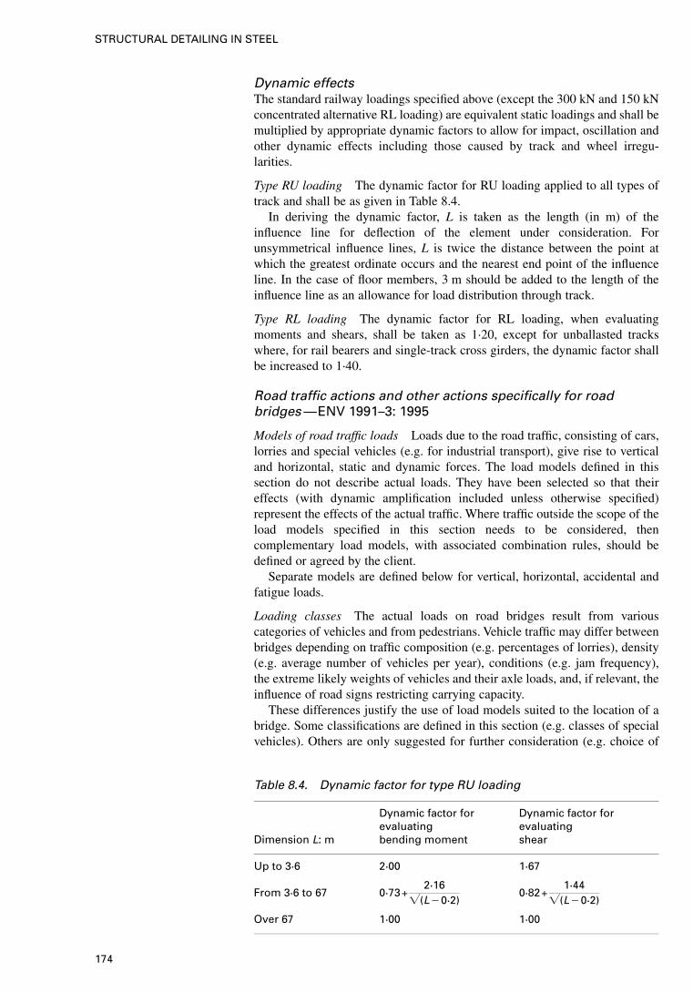
Dynamic effectsThe standard railway loadings specified above (except the 300 kN and 150 kNconcentrated alternative RL loading) are equivalent static loadings and shall bemultiplied by appropriate dynamic factors to allow for impact, oscillation andother dynamic effects including those caused by track and wheel irregu-larities.
Type RU loading The dynamic factor for RU loading applied to all types oftrack and shall be as given in Table 8.4.
In deriving the dynamic factor, L is taken as the length (in m) of theinfluence line for deflection of the element under consideration. Forunsymmetrical influence lines, L is twice the distance between the point atwhich the greatest ordinate occurs and the nearest end point of the influenceline. In the case of floor members, 3 m should be added to the length of theinfluence line as an allowance for load distribution through track.
Type RL loading The dynamic factor for RL loading, when evaluatingmoments and shears, shall be taken as 1·20, except for unballasted trackswhere, for rail bearers and single-track cross girders, the dynamic factor shallbe increased to 1·40.
Road traffic actions and other actions specifically for roadbridges—ENV 1991–3: 1995
Models of road traffic loads Loads due to the road traffic, consisting of cars,lorries and special vehicles (e.g. for industrial transport), give rise to verticaland horizontal, static and dynamic forces. The load models defined in thissection do not describe actual loads. They have been selected so that theireffects (with dynamic amplification included unless otherwise specified)represent the effects of the actual traffic. Where traffic outside the scope of theload models specified in this section needs to be considered, thencomplementary load models, with associated combination rules, should bedefined or agreed by the client.
Separate models are defined below for vertical, horizontal, accidental andfatigue loads.
Loading classes The actual loads on road bridges result from variouscategories of vehicles and from pedestrians. Vehicle traffic may differ betweenbridges depending on traffic composition (e.g. percentages of lorries), density(e.g. average number of vehicles per year), conditions (e.g. jam frequency),the extreme likely weights of vehicles and their axle loads, and, if relevant, theinfluence of road signs restricting carrying capacity.
These differences justify the use of load models suited to the location of abridge. Some classifications are defined in this section (e.g. classes of specialvehicles). Others are only suggested for further consideration (e.g. choice of
Table 8.4. Dynamic factor for type RU loading
Dynamic factor for Dynamic factor forevaluating evaluating
Dimension L: m bending moment shear
Up to 3·6 2·00 1·67
From 3·6 to 67 0·73+2·16
�(L�0·2)0·82+
1·44�(L�0·2)
Over 67 1·00 1·00
174
STRUCTURAL DETAILING IN STEEL
adjustment factors � and � defined in Clause 4.3.2(7) of the code for the mainmodel and in Clause 4.3.3 for the single axle model) and may be presented asloading classes (or traffic classes).
Divisions of the carriageway into notional lanes The widths wl of notionallanes on a carriageway and the greatest possible whole (integer) number nl ofsuch lanes on this carriageway are shown in Table 8.5.
8.1.2. Highways loads
based on EC3 loadings
Location and numbering of the lanes for design (EC3) (ENV1995)The location and numbering of the lanes should be determined in accordancewith the following rules:
(a) the locations of notional lanes are not necessarily related to theirnumbering
(b) for each individual verification (e.g. for a verification of the ultimatelimit states of resistance of a cross-section to bending), the number oflanes to be taken into account as loaded, their location on thecarriageway and their numbering should be so chosen that the effectsfrom the load models are the most adverse.
Vertical loads—characteristic values
General and associated design situations Characteristic loads are intendedfor the determination of road traffic effects associated with ultimate limit-stateverifications and with particular serviceability verifications (see ENV 1991-1,9.4.2 and 9.5.2, and ENV 1992 to 1995). The load models for vertical loadsrepresent the following traffic effects.
(a) Load model 1: concentrated and uniformly distributed loads, whichcover most of the effects of the traffic of lorries and cars. This model isintended for general and local verifications.
(b) Load model 2: a single axle load applied on specific tyre contact areaswhich covers the dynamic effects of normal traffic on very shortstructural elements. This model should be separately considered and isonly intended for local verifications.
(c) Load model 3: a set of assemblies of axle loads representing specialvehicles (e.g. for industrial transport) which may travel on routespermitted for abnormal loads. This model is intended to be used onlywhen, and as far as required by the client, for general and localverifications.
Table 8.5. Number and width of lanes
Carriageway Number of Width of a Width of thewidth w notional notional remaining
lanes lane area
w<5·4 m nl=1 3 m w�3 m
5·4 m�w<6 m nl=2w2
0
6 m�w nl= Int�w3� 3 m w�3�nl
Note: for example, for a carriageway width of 11 m, nl= Int�w3�=3, and the width of the
remaining area is 11�3�3=2 m.
175
STEEL BRIDGES
(d ) Load model 4: a crowd loading. This model should be considered onlywhen required by the client. It is intended only for general verifications.However, crowd loading may be usefully specified by the relevantauthority for bridges located in or near towns if its effects are notobviously covered by load model 1.
Load models 1 and 2 are defined numerically for persistent situations and areto be considered for any type of design situation (e.g. for transient situationsduring repair works). Load models 3 and 4 are defined only for some transientdesign situations. Design situations are specified as far as necessary in designEurocodes and/or in particular projects, in accordance with definitions andprinciples given in ENV 1991-1. Combinations for persistent and transientsituations may be numerically different.
Main loading system (load model 1)The main loading system consists of two partial systems as detailed below.
Double-axle concentrated loads (tandem system: TS), each axle having aweight:
�QQk
where:
�Q are adjustment factors.
No more than one tandem system should be considered per lane; onlycomplete tandem systems shall be considered. Each tandem system should belocated in the most adverse position in its lane (see, however, below and Fig.8.5. Each axle of the tandem model has two identical wheels, the load perwheel being therefore equal to 0·5�QQk. The contact surface of each wheel isto be taken as square and of side 0·40 m.
Uniformly distributed loads (UDL system), having a weight density per squaremetre:
�qqk (8.3)
where
�q are adjustment factors.
These loads should be applied only in the unfavourable parts of the influencesurface, longitudinally and transversally.
Load model 1 should be applied on each notional lane and on the remainingareas. On notional lane number 1, the load magnitudes are referred to as �QiQik
and �qiqik (Table 8.6). On the remaining areas, the load magnitude is referredto as �qr qrk .
Unless otherwise specified, the dynamic amplification is included in thevalues for Qik and qik, the values of which are given in Table 8.6.
For the assessment of general effects, the tandem systems may be assumedto travel along the axes of the notional lanes.
Where general and local effects can be calculated separately, and unlessotherwise specified by the client, the general effects may be calculated:
(a) by replacing the second and third tandem systems by a second tandemsystem with axle weight equal to
(200�Q2 +100�Q3) kN (although relevant authorities may restrict theapplication of this simplification) or
176
STRUCTURAL DETAILING IN STEEL
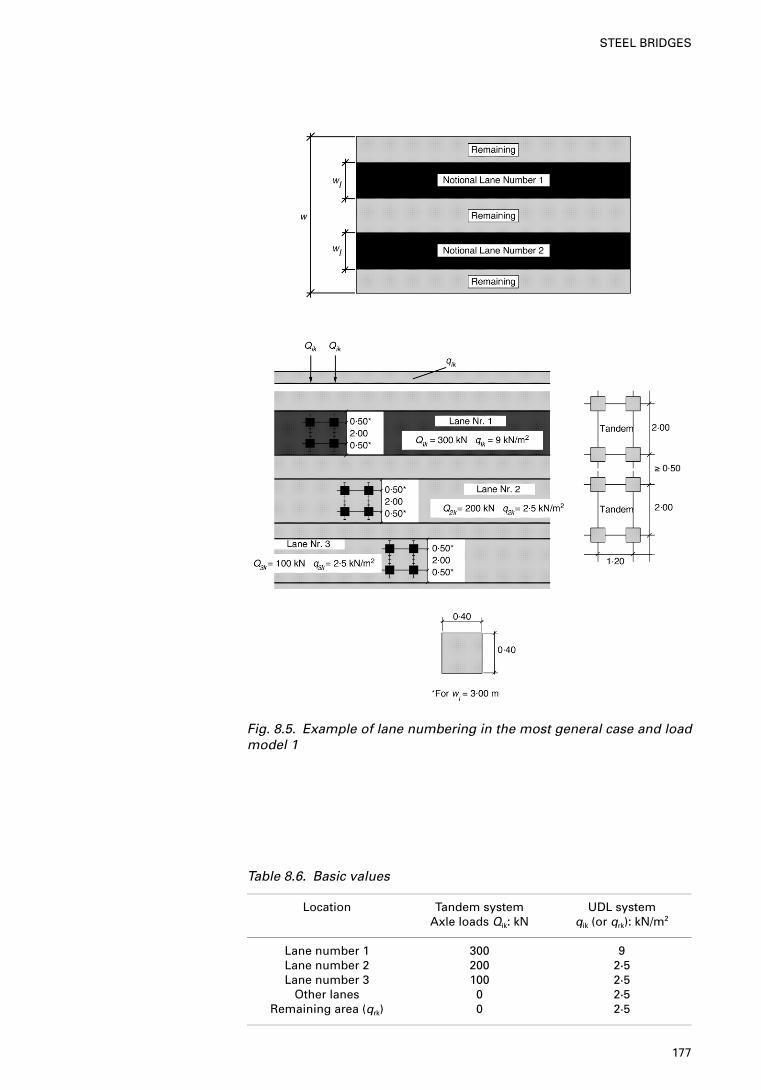
Fig. 8.5. Example of lane numbering in the most general case and loadmodel 1
Table 8.6. Basic values
Location Tandem system UDL systemAxle loads Qik: kN qik (or qrk): kN/m2
Lane number 1 300 9Lane number 2 200 2·5Lane number 3 100 2·5
Other lanes 0 2·5Remaining area (qrk) 0 2·5
177
STEEL BRIDGES
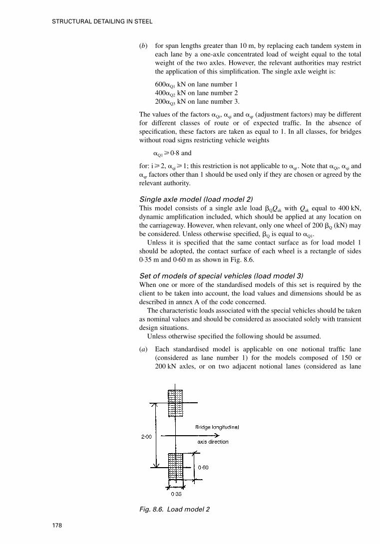
(b) for span lengths greater than 10 m, by replacing each tandem system ineach lane by a one-axle concentrated load of weight equal to the totalweight of the two axles. However, the relevant authorities may restrictthe application of this simplification. The single axle weight is:
600�Q1 kN on lane number 1400�Q2 kN on lane number 2200�Q3 kN on lane number 3.
The values of the factors �Qi, �qi and �qr (adjustment factors) may be differentfor different classes of route or of expected traffic. In the absence ofspecification, these factors are taken as equal to 1. In all classes, for bridgeswithout road signs restricting vehicle weights
�Q1 �0·8 and
for: i�2, �qi �1; this restriction is not applicable to �qr . Note that �Qi, �qi and�qr factors other than 1 should be used only if they are chosen or agreed by therelevant authority.
Single axle model (load model 2)This model consists of a single axle load �QQak with Qak equal to 400 kN,dynamic amplification included, which should be applied at any location onthe carriageway. However, when relevant, only one wheel of 200 �Q (kN) maybe considered. Unless otherwise specified, �Q is equal to �Q1.
Unless it is specified that the same contact surface as for load model 1should be adopted, the contact surface of each wheel is a rectangle of sides0·35 m and 0·60 m as shown in Fig. 8.6.
Set of models of special vehicles (load model 3)When one or more of the standardised models of this set is required by theclient to be taken into account, the load values and dimensions should be asdescribed in annex A of the code concerned.
The characteristic loads associated with the special vehicles should be takenas nominal values and should be considered as associated solely with transientdesign situations.
Unless otherwise specified the following should be assumed.
(a) Each standardised model is applicable on one notional traffic lane(considered as lane number 1) for the models composed of 150 or200 kN axles, or on two adjacent notional lanes (considered as lane
Fig. 8.6. Load model 2
178
STRUCTURAL DETAILING IN STEEL
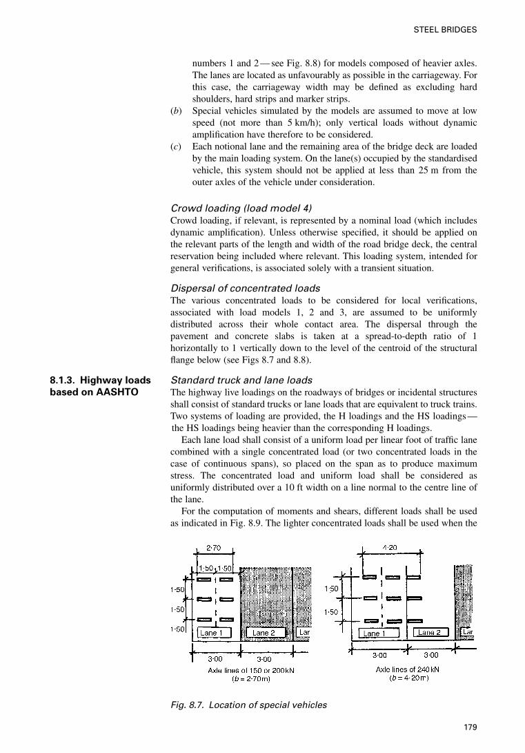
numbers 1 and 2 — see Fig. 8.8) for models composed of heavier axles.The lanes are located as unfavourably as possible in the carriageway. Forthis case, the carriageway width may be defined as excluding hardshoulders, hard strips and marker strips.
(b) Special vehicles simulated by the models are assumed to move at lowspeed (not more than 5 km/h); only vertical loads without dynamicamplification have therefore to be considered.
(c) Each notional lane and the remaining area of the bridge deck are loadedby the main loading system. On the lane(s) occupied by the standardisedvehicle, this system should not be applied at less than 25 m from theouter axles of the vehicle under consideration.
Crowd loading (load model 4)Crowd loading, if relevant, is represented by a nominal load (which includesdynamic amplification). Unless otherwise specified, it should be applied onthe relevant parts of the length and width of the road bridge deck, the centralreservation being included where relevant. This loading system, intended forgeneral verifications, is associated solely with a transient situation.
Dispersal of concentrated loadsThe various concentrated loads to be considered for local verifications,associated with load models 1, 2 and 3, are assumed to be uniformlydistributed across their whole contact area. The dispersal through thepavement and concrete slabs is taken at a spread-to-depth ratio of 1horizontally to 1 vertically down to the level of the centroid of the structuralflange below (see Figs 8.7 and 8.8).
8.1.3. Highway loads
based on AASHTO
Standard truck and lane loadsThe highway live loadings on the roadways of bridges or incidental structuresshall consist of standard trucks or lane loads that are equivalent to truck trains.Two systems of loading are provided, the H loadings and the HS loadings —the HS loadings being heavier than the corresponding H loadings.
Each lane load shall consist of a uniform load per linear foot of traffic lanecombined with a single concentrated load (or two concentrated loads in thecase of continuous spans), so placed on the span as to produce maximumstress. The concentrated load and uniform load shall be considered asuniformly distributed over a 10 ft width on a line normal to the centre line ofthe lane.
For the computation of moments and shears, different loads shall be usedas indicated in Fig. 8.9. The lighter concentrated loads shall be used when the
Fig. 8.7. Location of special vehicles
179
STEEL BRIDGES
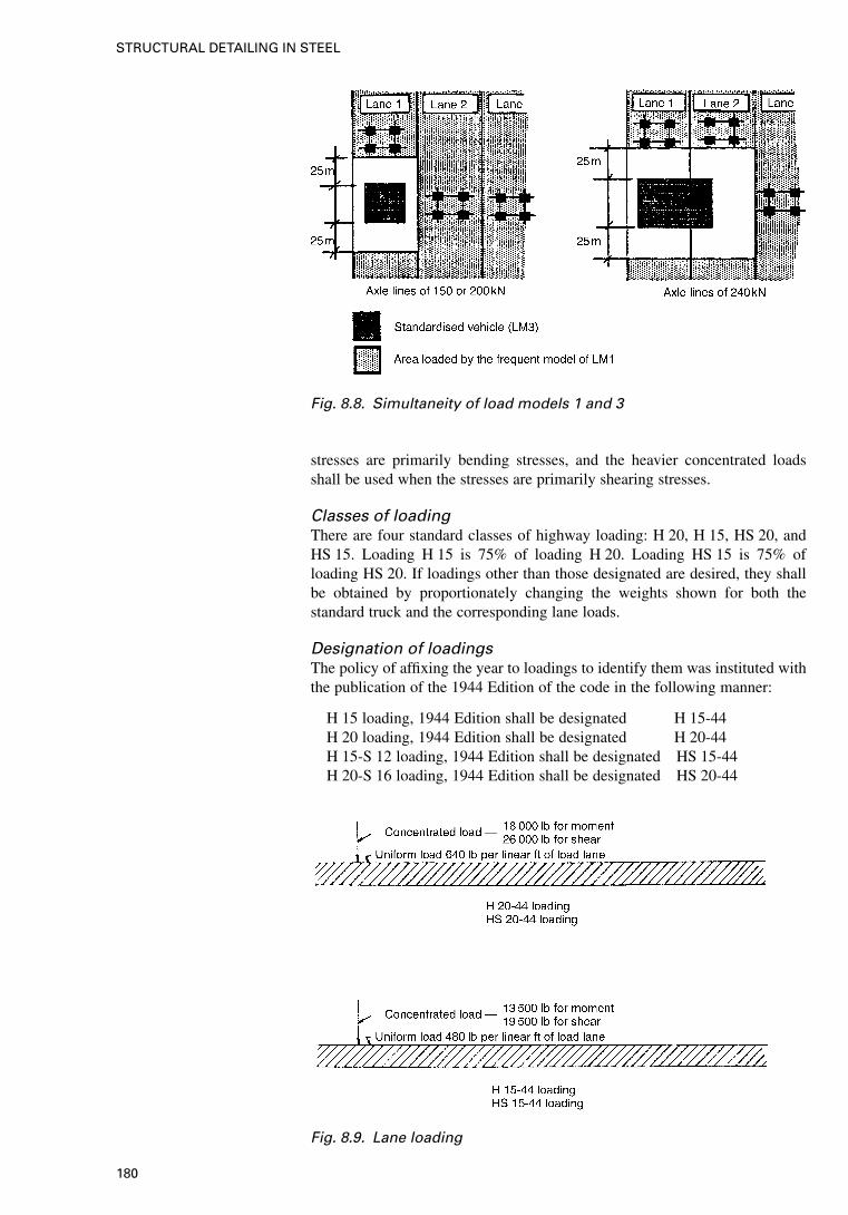
stresses are primarily bending stresses, and the heavier concentrated loadsshall be used when the stresses are primarily shearing stresses.
Classes of loadingThere are four standard classes of highway loading: H 20, H 15, HS 20, andHS 15. Loading H 15 is 75% of loading H 20. Loading HS 15 is 75% ofloading HS 20. If loadings other than those designated are desired, they shallbe obtained by proportionately changing the weights shown for both thestandard truck and the corresponding lane loads.
Designation of loadingsThe policy of affixing the year to loadings to identify them was instituted withthe publication of the 1944 Edition of the code in the following manner:
H 15 loading, 1944 Edition shall be designated H 15-44H 20 loading, 1944 Edition shall be designated H 20-44H 15-S 12 loading, 1944 Edition shall be designated HS 15-44H 20-S 16 loading, 1944 Edition shall be designated HS 20-44
Fig. 8.8. Simultaneity of load models 1 and 3
Fig. 8.9. Lane loading
180
STRUCTURAL DETAILING IN STEEL
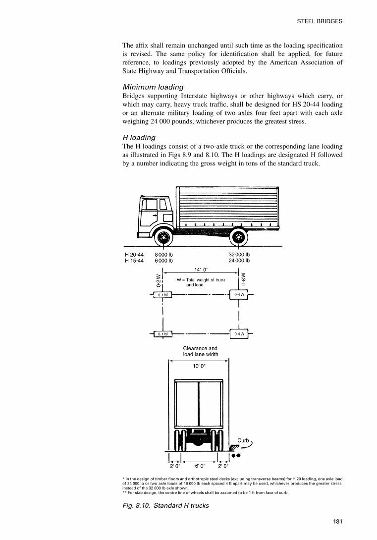
The affix shall remain unchanged until such time as the loading specificationis revised. The same policy for identification shall be applied, for futurereference, to loadings previously adopted by the American Association ofState Highway and Transportation Officials.
Minimum loadingBridges supporting Interstate highways or other highways which carry, orwhich may carry, heavy truck traffic, shall be designed for HS 20-44 loadingor an alternate military loading of two axles four feet apart with each axleweighing 24 000 pounds, whichever produces the greatest stress.
H loadingThe H loadings consist of a two-axle truck or the corresponding lane loadingas illustrated in Figs 8.9 and 8.10. The H loadings are designated H followedby a number indicating the gross weight in tons of the standard truck.
* In the design of timber floors and orthotropic steel decks (excluding transverse beams) for H 20 loading, one axle loadof 24 000 lb or two axle loads of 16 000 lb each spaced 4 ft apart may be used, whichever produces the greater stress,instead of the 32 000 lb axle shown.** For slab design, the centre line of wheels shall be assumed to be 1 ft from face of curb.
Fig. 8.10. Standard H trucks
181
STEEL BRIDGES
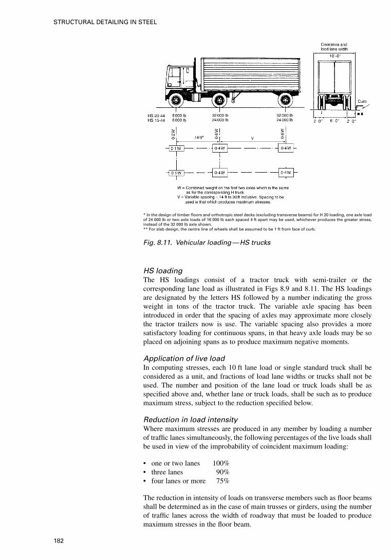
HS loadingThe HS loadings consist of a tractor truck with semi-trailer or thecorresponding lane load as illustrated in Figs 8.9 and 8.11. The HS loadingsare designated by the letters HS followed by a number indicating the grossweight in tons of the tractor truck. The variable axle spacing has beenintroduced in order that the spacing of axles may approximate more closelythe tractor trailers now is use. The variable spacing also provides a moresatisfactory loading for continuous spans, in that heavy axle loads may be soplaced on adjoining spans as to produce maximum negative moments.
Application of live loadIn computing stresses, each 10 ft lane load or single standard truck shall beconsidered as a unit, and fractions of load lane widths or trucks shall not beused. The number and position of the lane load or truck loads shall be asspecified above and, whether lane or truck loads, shall be such as to producemaximum stress, subject to the reduction specified below.
Reduction in load intensityWhere maximum stresses are produced in any member by loading a numberof traffic lanes simultaneously, the following percentages of the live loads shallbe used in view of the improbability of coincident maximum loading:
• one or two lanes 100%• three lanes 90%• four lanes or more 75%
The reduction in intensity of loads on transverse members such as floor beamsshall be determined as in the case of main trusses or girders, using the numberof traffic lanes across the width of roadway that must be loaded to producemaximum stresses in the floor beam.
* In the design of timber floors and orthotropic steel decks (excluding transverse beams) for H 20 loading, one axle loadof 24 000 lb or two axle loads of 16 000 lb each spaced 4 ft apart may be used, whichever produces the greater stress,instead of the 32 000 lb axle shown.** For slab design, the centre line of wheels shall be assumed to be 1 ft from face of curb.
Fig. 8.11. Vehicular loading—HS trucks
182
STRUCTURAL DETAILING IN STEEL
Sidewalk, curb, and railing loadingSidewalk floors, stringers, and their immediate supports shall be designed fora live load of 85 lb/ft2 of sidewalk area. Girders, trusses, arches and othermembers shall be designed for the following sidewalk live loads:
• spans 0–25 ft in length 85 lb/ft2
• spans 26–100 ft in length 60 lb/ft2
• spans over 100 ft in length according to the formula
P=�30 +3000
L ��55�W50 � (8.4)
in which
P=live load per ft2, max. 60 lb/ft2
L=loaded length of sidewalk in ftW=width of sidewalk in ft.
In calculating stresses in structures that support cantilevered sidewalks, thesidewalk shall be fully loaded on only one side of the structure if this conditionproduces maximum stress.
Bridges for pedestrian and/or bicycle traffic shall be designed for a live loadof 85 PSF. Where bicycle or pedestrian bridges are expected to be used bymaintenance vehicles, special design consideration should be allowed forthese loads.
Curbs shall be designed to resist a lateral force of not less than 500 lb perlinear ft of curb, applied at the top of the curb, or at an elevation 10 in. abovethe floor if the curb is higher than 10 in. Where sidewalk, curb, and traffic railform an integral system, the traffic railing loading shall be applied and stressesin curbs computed accordingly.
Superstructure design
Group II and Group V loadings A wind load of the following intensity shallbe applied horizontally at right angles to the longitudinal axis of thestructure:
• for trusses and arches 75 lb/ft2
• for girders and beams 50 lb/ft2
The total force shall not be less than 300 lb per linear ft in the plane of thewindward chord and 150 lb per linear ft in the plane of the leeward chord ontruss spans, and not less than 300 lb per linear ft on girder spans.
Group III and Group VI loadings Group III and Group VI loadings shallcomprise the loads used for Group II and Group V loadings reduced by 70%and a load of 100 lb per linear ft applied at right angles to the longitudinal axisof the structure and 6 ft above the deck as a wind load on a moving live load.When a reinforced concrete floor slab or a steel grid deck is keyed to orattached to its supporting members, it may be assumed that the deck resists,within its plane, the shear resulting from the wind load on the moving liveload.
Combinations of loadsThe following Group represents various combinations of loads and forces towhich a structure may be subjected. Each component of the structure, or thefoundation on which it rests, shall be proportioned to withstand safely all
183
STEEL BRIDGES
group combinations of these forces that are applicable to the particular site ortype. Group loading combinations for service load design and load factordesign are given by the following.
Group (N)=�[�D · D+�L(L+I)+�CCF+�EE
+�BB+�SSF+�WW+�WLWL
+�L · LF+�R(R+S+T)
+�EQEQ+�ICEICE]
where
N =group number� =load factor, see Table 8.7� =coefficient, see Table 8.7D =dead loadL =live loadI =live load impactE =earth pressureB =buoyancyW =wind load on structureWL =wind load on live load — 100 lb per linear ftLF =longitudinal force from live loadCF =centrifugal forceR =rib shorteningS =shrinkageT =temperatureEQ =earthquakeSF =stream flow pressureICE=ice pressure.
For service load design, the percentage of the basic unit stress for the variousgroups is given in Table 8.7. The loads and forces in each group shall be takenas appropriate. The maximum section required shall be used.
For load factor design, the gamma and beta factors given in Table 8.7 shallbe used for designing structural members and foundations by the load factorconcept.
A simpler, more tractable model has been developed. The objective of thismodel is to prescribe a set of loads such that the same extreme load effects ofthe model are approximately the same as the exclusion vehicles. This modelconsists of three distinctly different loads:
• design truck• design tandem• design lane.
As illustrated in Fig. 8.11, the design truck (the first of three separate live loadconfigurations) is a model load that resembles the typical semi-trailer truck.The front axle is 35 kN, located 4300 mm before the drive axle which has aload of 145 kN. The rear trailer axle is also 145 kN and is positioned at avariable distance ranging between 4300 and 9000 mm. The variable rangemeans that the spacing used should cause critical load effect. The long spacingtypically only controls where the front and rear portions of the truck may bepositioned in adjacent structurally continuous spans such as for continuousshort-span bridges. The design truck is the same configuration that has beenused by AASHTO (1996) Standard Specification since 1944 and is commonlyreferred to as HS 20. The H denotes highway, the S denotes semi-trailer, and
184
STRUCTURAL DETAILING IN STEEL
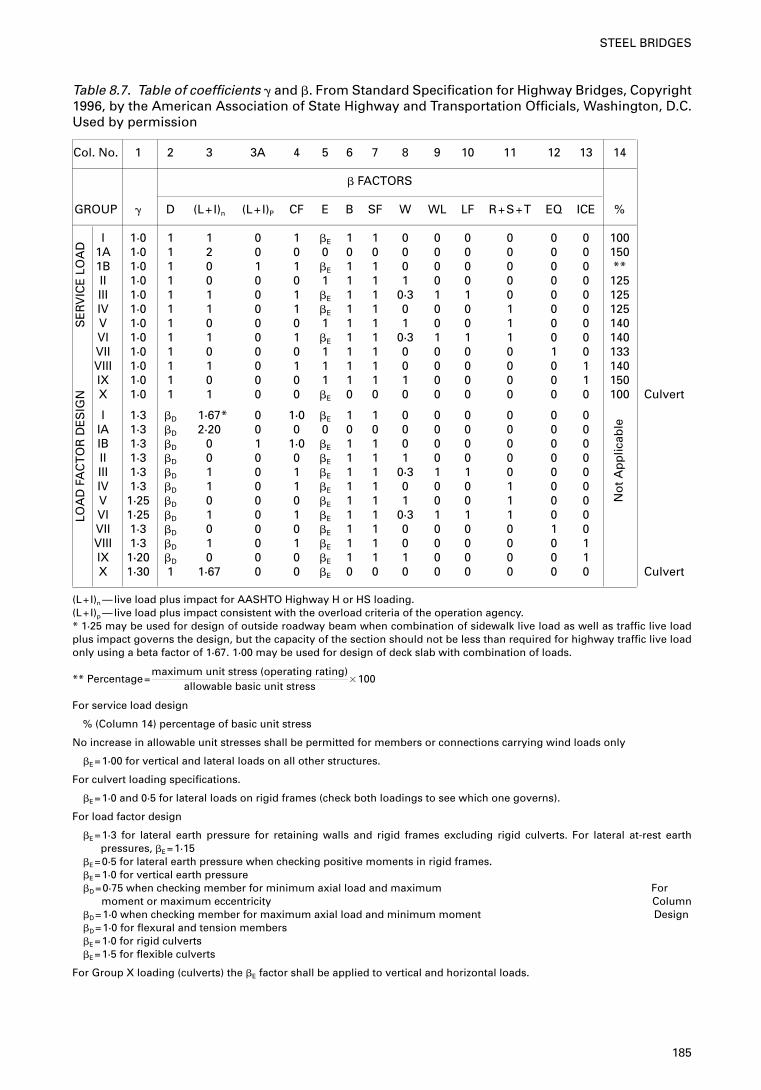
Table 8.7. Table of coefficients � and �. From Standard Specification for Highway Bridges, Copyright1996, by the American Association of State Highway and Transportation Officials, Washington, D.C.Used by permission
Col. No. 1 2 3 3A 4 5 6 7 8 9 10 11 12 13 14
� FACTORS
GROUP � D (L+I)n (L+I)P CF E B SF W WL LF R+S+T EQ ICE %
I 1·0 1 1 0 1 �E 1 1 0 0 0 0 0 0 1001A 1·0 1 2 0 0 0 0 0 0 0 0 0 0 0 1501B 1·0 1 0 1 1 �E 1 1 0 0 0 0 0 0 **II 1·0 1 0 0 0 1 1 1 1 0 0 0 0 0 125III 1·0 1 1 0 1 �E 1 1 0·3 1 1 0 0 0 125IV 1·0 1 1 0 1 �E 1 1 0 0 0 1 0 0 125V 1·0 1 0 0 0 1 1 1 1 0 0 1 0 0 140VI 1·0 1 1 0 1 �E 1 1 0·3 1 1 1 0 0 140VII 1·0 1 0 0 0 1 1 1 0 0 0 0 1 0 133VIII 1·0 1 1 0 1 1 1 1 0 0 0 0 0 1 140IX 1·0 1 0 0 0 1 1 1 1 0 0 0 0 1 150X 1·0 1 1 0 0 �E 0 0 0 0 0 0 0 0 100 Culvert
I 1·3 �D 1·67* 0 1·0 �E 1 1 0 0 0 0 0 0IA 1·3 �D 2·20 0 0 0 0 0 0 0 0 0 0 0IB 1·3 �D 0 1 1·0 �E 1 1 0 0 0 0 0 0II 1·3 �D 0 0 0 �E 1 1 1 0 0 0 0 0III 1·3 �D 1 0 1 �E 1 1 0·3 1 1 0 0 0IV 1·3 �D 1 0 1 �E 1 1 0 0 0 1 0 0V 1·25 �D 0 0 0 �E 1 1 1 0 0 1 0 0VI 1·25 �D 1 0 1 �E 1 1 0·3 1 1 1 0 0VII 1·3 �D 0 0 0 �E 1 1 0 0 0 0 1 0VIII 1·3 �D 1 0 1 �E 1 1 0 0 0 0 0 1IX 1·20 �D 0 0 0 �E 1 1 1 0 0 0 0 1X 1·30 1 1·67 0 0 �E 0 0 0 0 0 0 0 0 Culvert
(L+I)n —live load plus impact for AASHTO Highway H or HS loading.(L+I)p —live load plus impact consistent with the overload criteria of the operation agency.* 1·25 may be used for design of outside roadway beam when combination of sidewalk live load as well as traffic live loadplus impact governs the design, but the capacity of the section should not be less than required for highway traffic live loadonly using a beta factor of 1·67. 1·00 may be used for design of deck slab with combination of loads.
** Percentage=maximum unit stress (operating rating)
allowable basic unit stress�100
For service load design
% (Column 14) percentage of basic unit stress
No increase in allowable unit stresses shall be permitted for members or connections carrying wind loads only
�E=1·00 for vertical and lateral loads on all other structures.
For culvert loading specifications.
�E=1·0 and 0·5 for lateral loads on rigid frames (check both loadings to see which one governs).
For load factor design
�E=1·3 for lateral earth pressure for retaining walls and rigid frames excluding rigid culverts. For lateral at-rest earthpressures, �E=1·15
�E=0·5 for lateral earth pressure when checking positive moments in rigid frames.�E=1·0 for vertical earth pressure�D=0·75 when checking member for minimum axial load and maximum For
moment or maximum eccentricity Column�D=1·0 when checking member for maximum axial load and minimum moment Design�D=1·0 for flexural and tension members�E=1·0 for rigid culverts�E=1·5 for flexible culverts
For Group X loading (culverts) the �E factor shall be applied to vertical and horizontal loads.
LOA
D F
AC
TO
R D
ES
IGN
SE
RV
ICE
LO
AD
No
t A
pp
licab
le
185
STEEL BRIDGES
the 20 is the weight of the tractor in tons (U.S. customary units). The newvehicle combinations as described in AASHTO (1994) LRFD BridgeSpecifications are designated as HL-93 for highway loading accepted in 1993(see Fig. 8.12).
The second configuration is the design tandem which consists of two axlesweighing 110 kN each spaced at 1200 mm, which is similar to the tandem axleused in previous AASHTO Standard Specifications except that the load ischanged from 24 to 25 kips (110 kN).
The third load is the design lane load that consists of a uniformlydistributed load of 9.3 N/mm and is assumed to occupy a region 3000 mmtransversely. This load is the same as a uniform pressure of 64 lb/ft2 (3·1 kPa)applied in a 10 ft (3000 mm) design lane. This load is similar to the lane loadoutlined in the AASHTO Standard Specifications for many years with theexception that the LRFD lane load does not require any concentrated loads.
The load effects of the design truck and the design tandem must each besuperimposed with the load effects of the design lane load. This combinationof lane and axle loads is a major deviation from the requirements of the earlierAASHTO Standard Specifications, where the loads were considered sepa-rately. It is important to understand that these loads are not designed to modelany one vehicle or combination of vehicles, but rather the spectra of loads andtheir associated load effects.
186
STRUCTURAL DETAILING IN STEEL
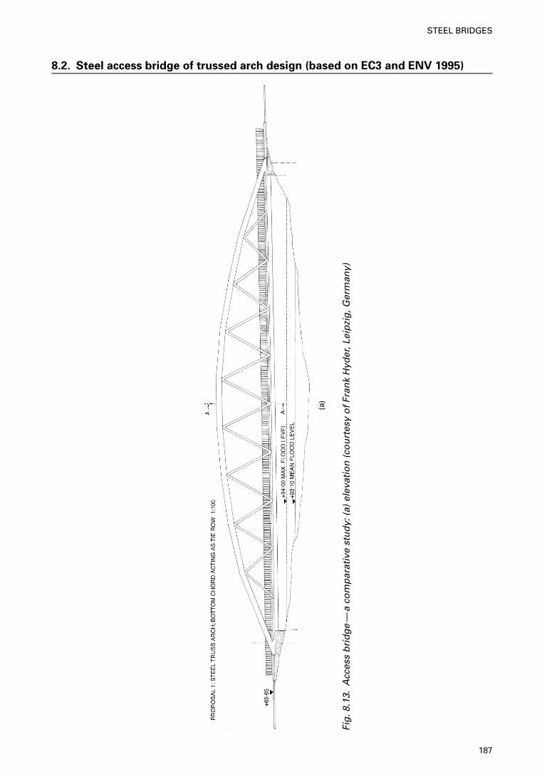
8.2. Steel access bridge of trussed arch design (based on EC3 and ENV 1995)
Fig
.8.1
3.A
cces
s b
rid
ge
—a
com
par
ativ
e st
ud
y: (
a) e
leva
tio
n (
cou
rtes
y o
f Fr
ank
Hyd
er, L
eip
zig
, Ger
man
y)
187
STEEL BRIDGES
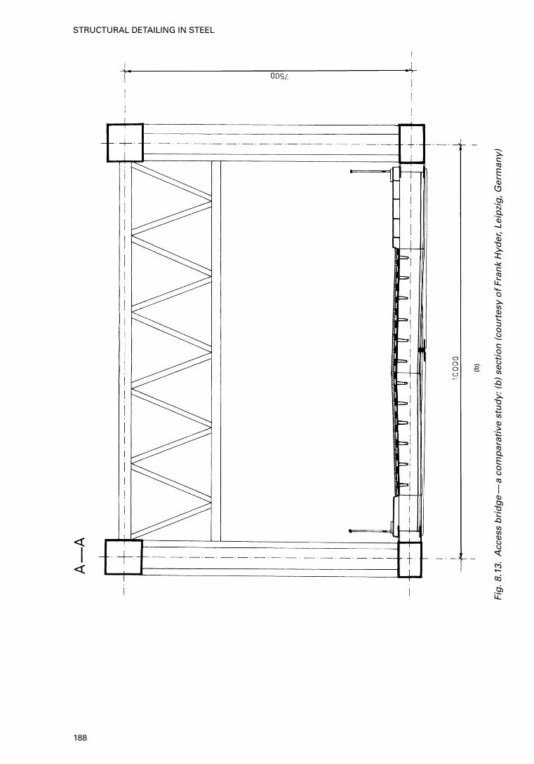
Fig
.8.1
3.A
cces
s b
rid
ge
—a
com
par
ativ
e st
ud
y: (
b)
sect
ion
(co
urt
esy
of
Fran
k H
yder
, Lei
pzi
g, G
erm
any)
188
STRUCTURAL DETAILING IN STEEL
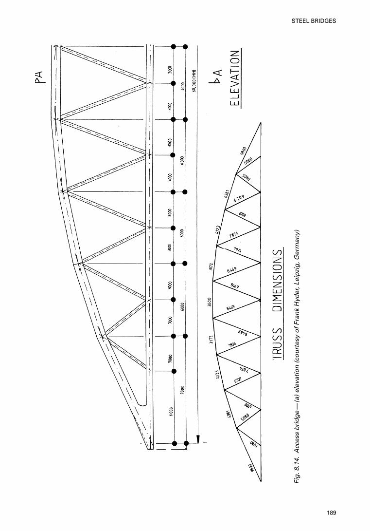
Fig
.8.1
4.A
cces
s b
rid
ge
—(a
) el
evat
ion
(co
urt
esy
of
Fran
k H
yder
, Lei
pzi
g, G
erm
any)
189
STEEL BRIDGES
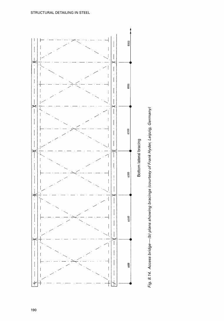
Fig
.8.1
4.A
cces
s b
rid
ge
—(b
) p
lan
s sh
ow
ing
bra
cin
gs
(co
urt
esy
of
Fran
k H
yder
, Lei
pzi
g, G
erm
any)
190
STRUCTURAL DETAILING IN STEEL
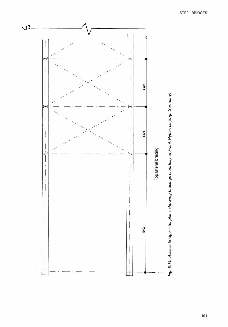
Fig
.8.1
4.A
cces
s b
rid
ge
—(c
) p
lan
s sh
ow
ing
bra
cin
gs
(co
urt
esy
of
Fran
k H
yder
, Lei
pzi
g, G
erm
any)
191
STEEL BRIDGES
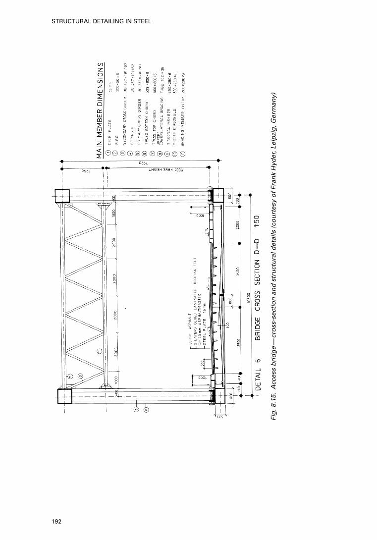
Fig
.8.1
5.A
cces
s b
rid
ge
—cr
oss
-sec
tio
n a
nd
str
uct
ura
l det
ails
(co
urt
esy
of
Fran
k H
yder
, Lei
pzi
g, G
erm
any)
192
STRUCTURAL DETAILING IN STEEL
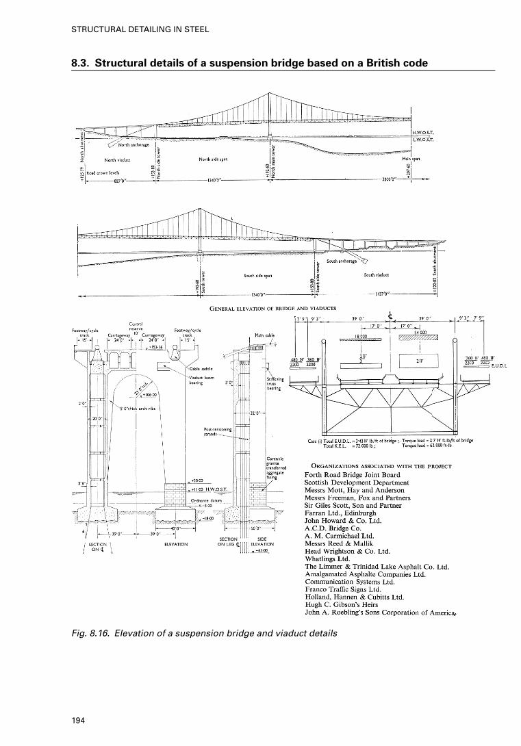
8.3. Structural details of a suspension bridge based on a British code
Fig. 8.16. Elevation of a suspension bridge and viaduct details
194
STRUCTURAL DETAILING IN STEEL
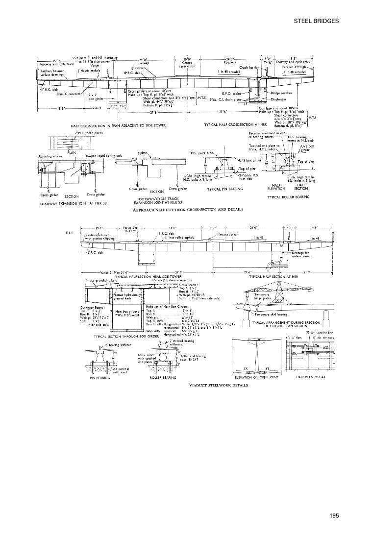
195
STEEL BRIDGES
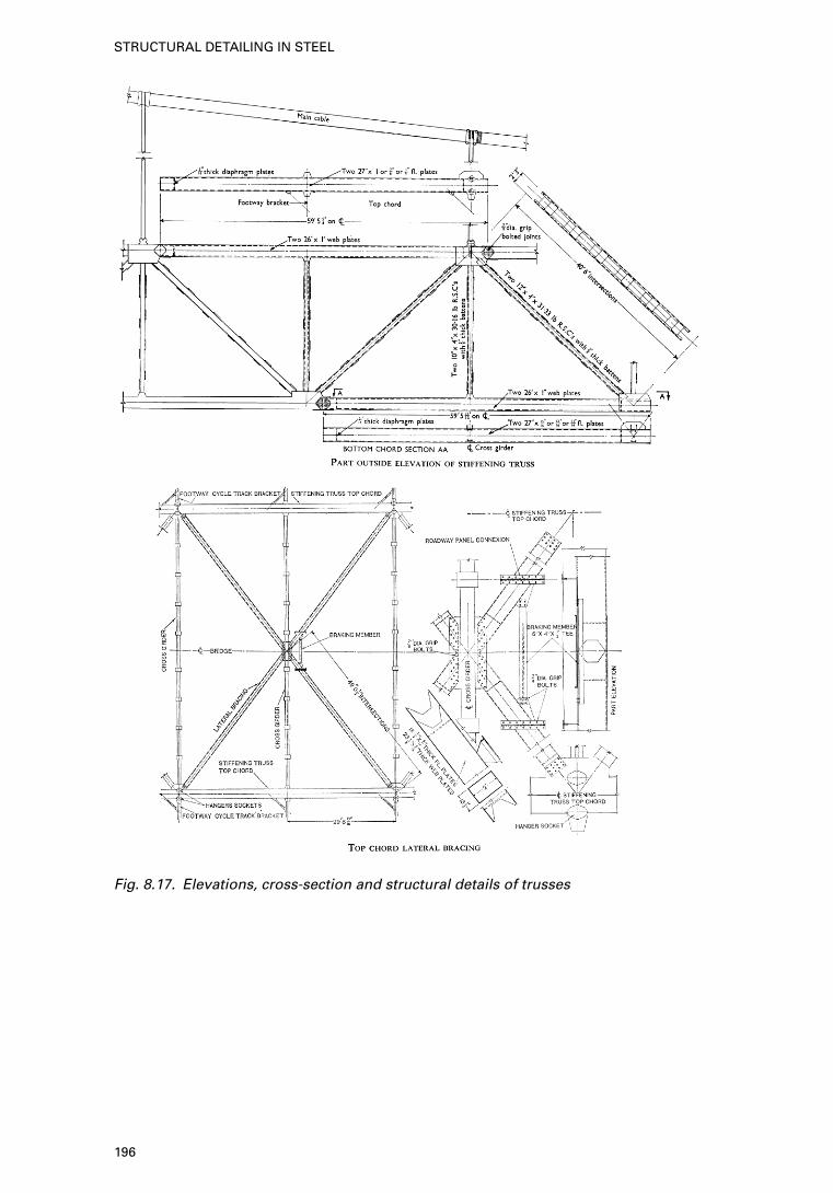
Fig. 8.17. Elevations, cross-section and structural details of trusses
196
STRUCTURAL DETAILING IN STEEL
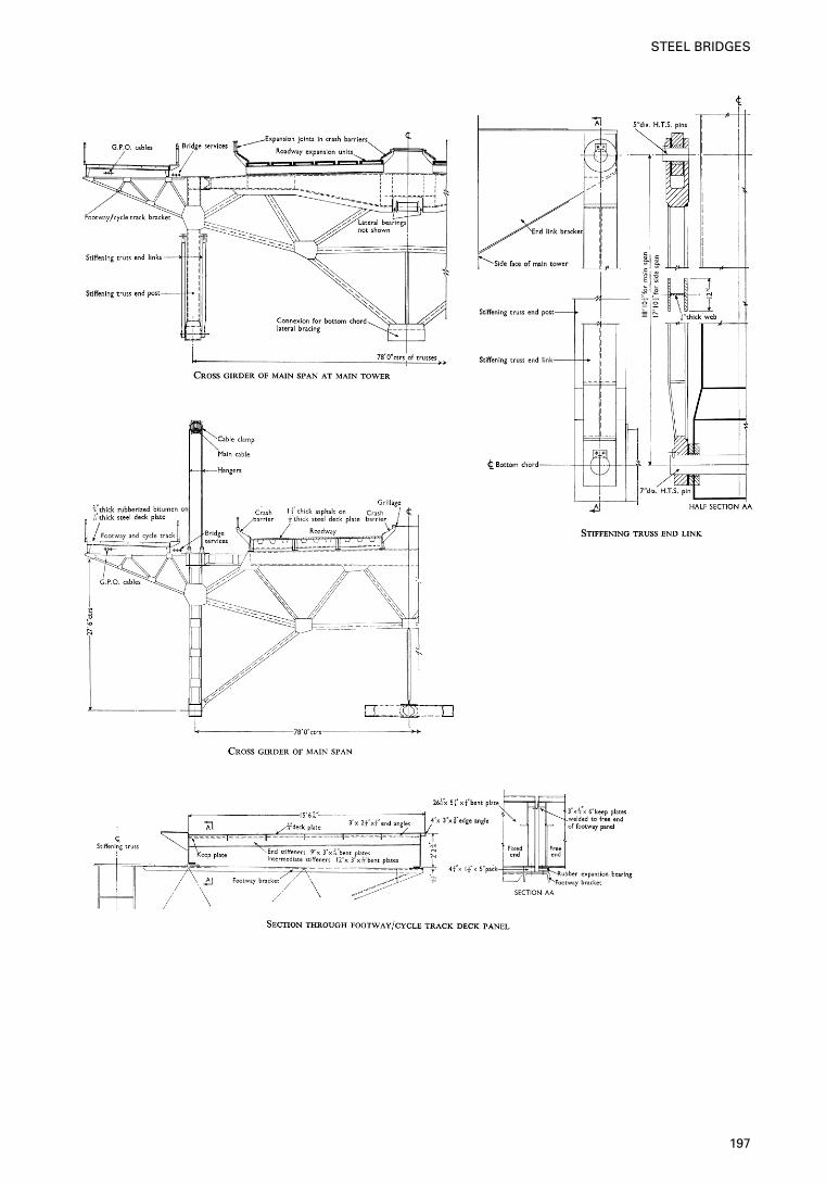
197
STEEL BRIDGES
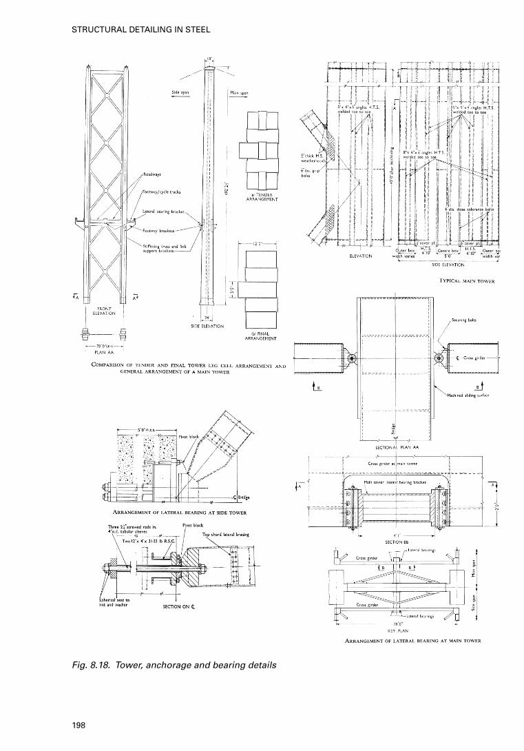
Fig. 8.18. Tower, anchorage and bearing details
198
STRUCTURAL DETAILING IN STEEL
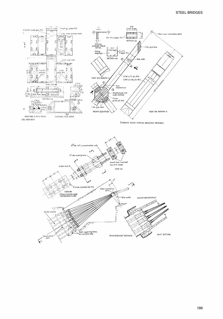
199
STEEL BRIDGES
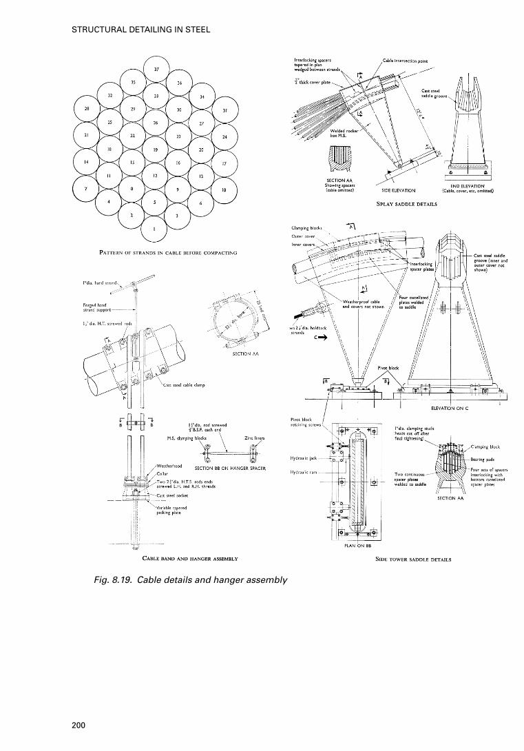
Fig. 8.19. Cable details and hanger assembly
200
STRUCTURAL DETAILING IN STEEL
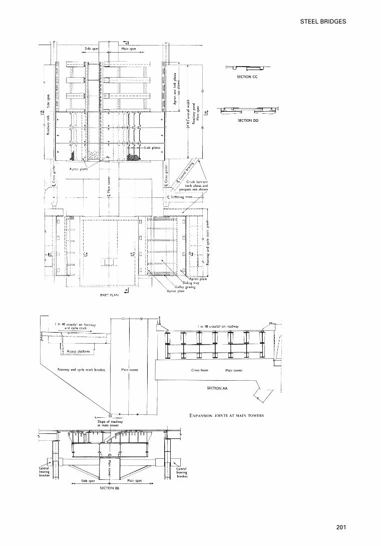
201
STEEL BRIDGES
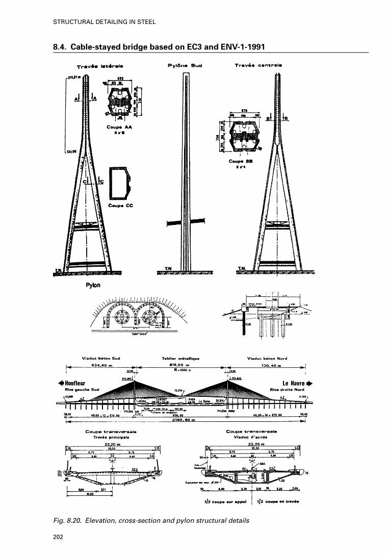
8.4. Cable-stayed bridge based on EC3 and ENV-1-1991
Fig. 8.20. Elevation, cross-section and pylon structural details
202
STRUCTURAL DETAILING IN STEEL
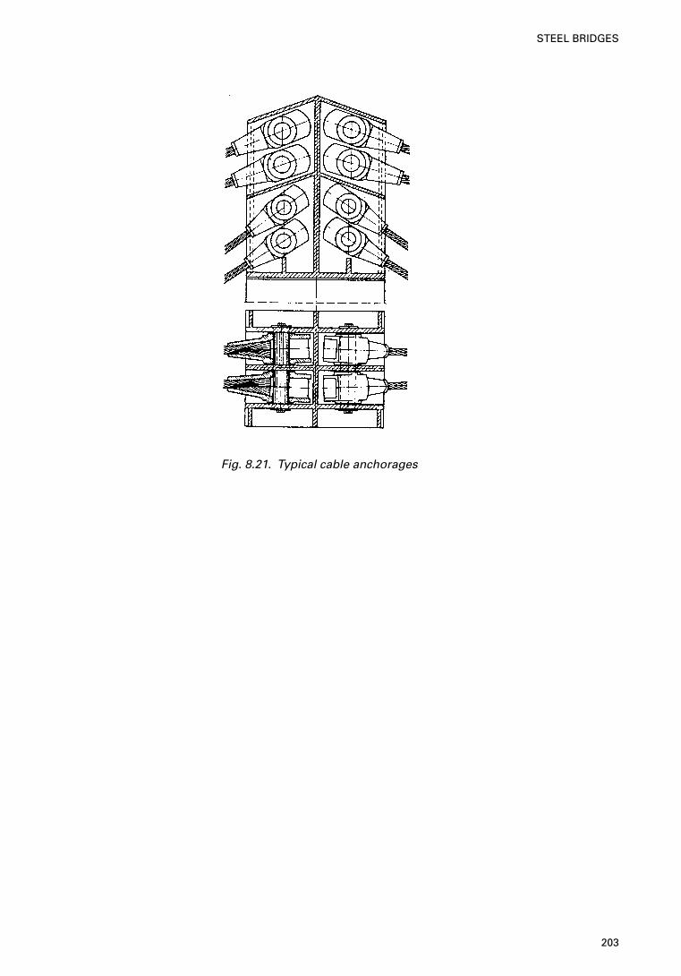
Fig. 8.21. Typical cable anchorages
203
STEEL BRIDGES
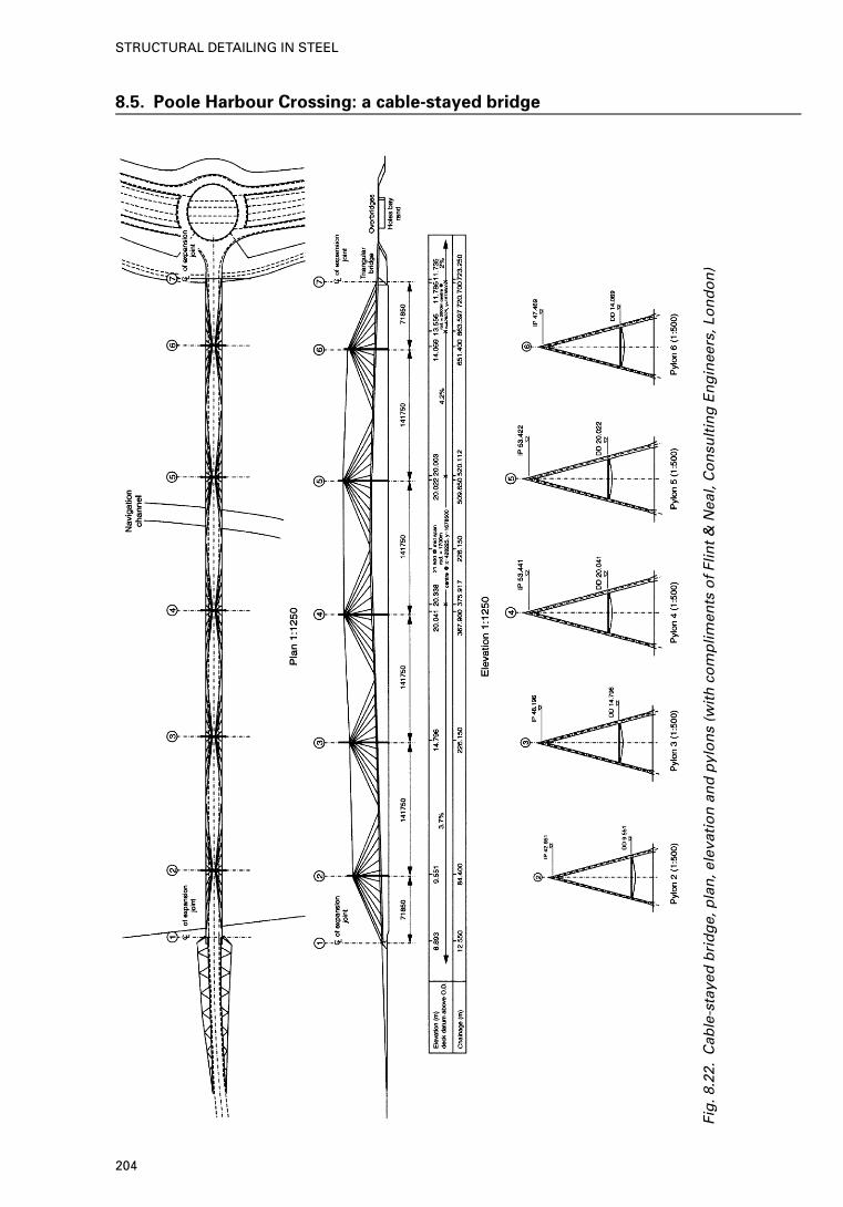
8.5. Poole Harbour Crossing: a cable-stayed bridge
Fig
.8.2
2.C
able
-sta
yed
bri
dg
e, p
lan
, ele
vati
on
an
d p
ylo
ns
(wit
h c
om
plim
ents
of
Flin
t &
Nea
l, C
on
sult
ing
En
gin
eers
, Lo
nd
on
)
204
STRUCTURAL DETAILING IN STEEL
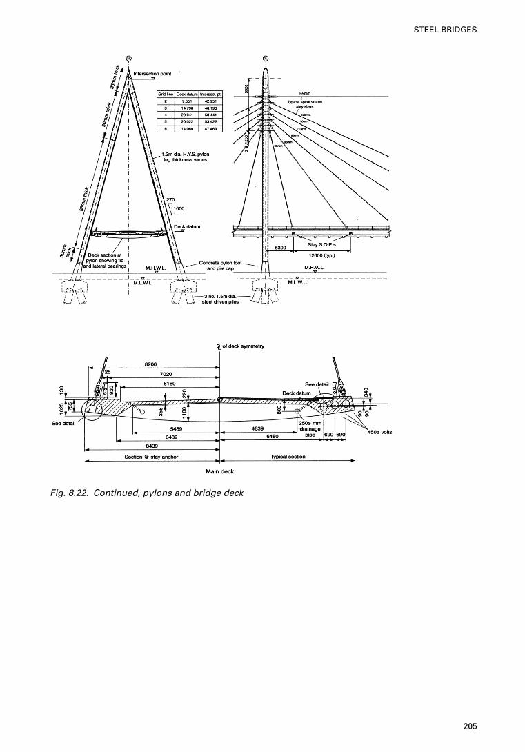
Fig. 8.22. Continued, pylons and bridge deck
205
STEEL BRIDGES
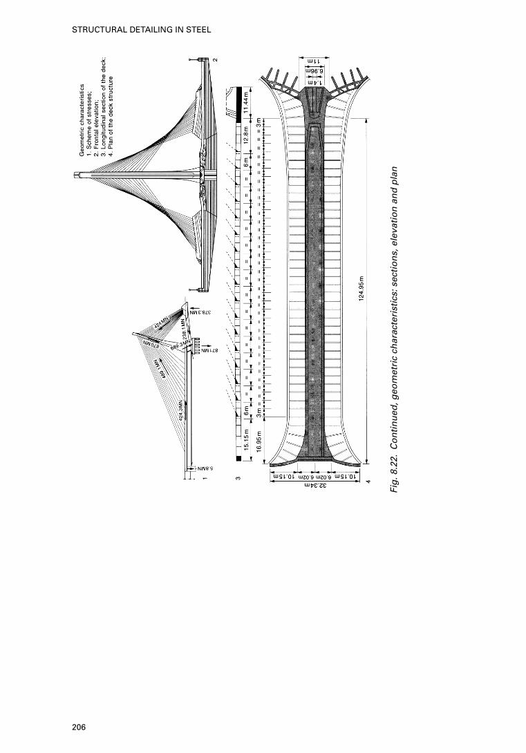
Fig
.8.2
2.C
on
tin
ued
, geo
met
ric
char
acte
rist
ics:
sec
tio
ns,
ele
vati
on
an
d p
lan
206
STRUCTURAL DETAILING IN STEEL
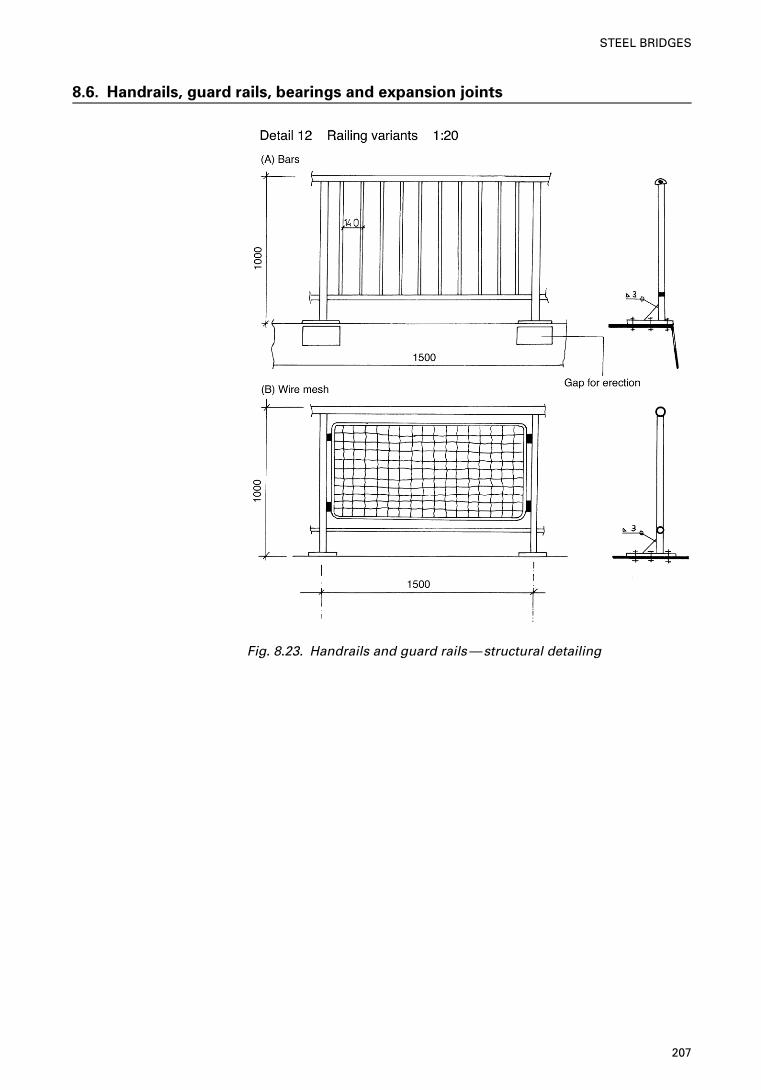
8.6. Handrails, guard rails, bearings and expansion joints
Fig. 8.23. Handrails and guard rails—structural detailing
207
STEEL BRIDGES
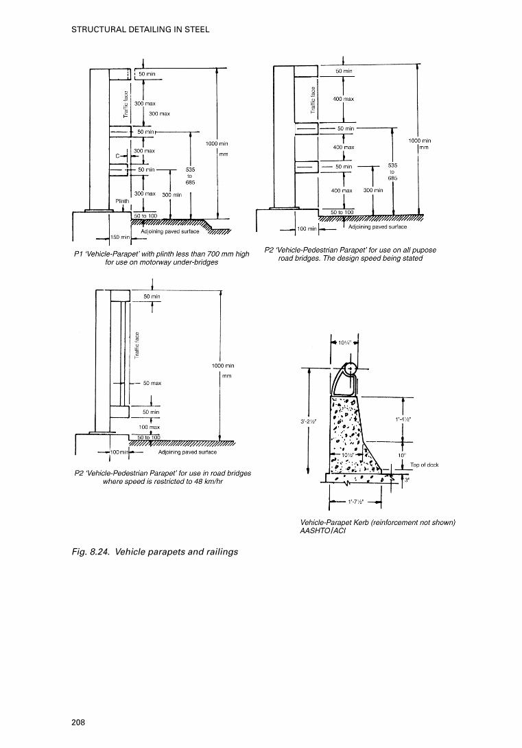
Fig. 8.24. Vehicle parapets and railings
208
STRUCTURAL DETAILING IN STEEL
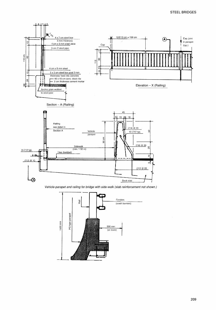
209
STEEL BRIDGES
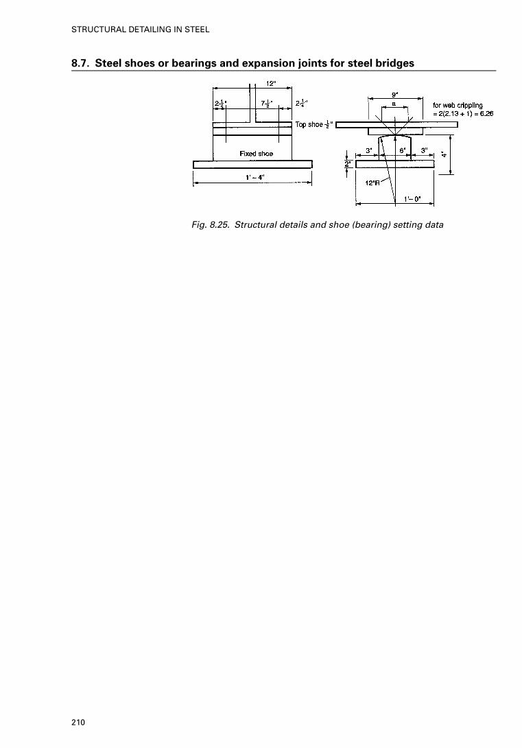
8.7. Steel shoes or bearings and expansion joints for steel bridges
Fig. 8.25. Structural details and shoe (bearing) setting data
210
STRUCTURAL DETAILING IN STEEL
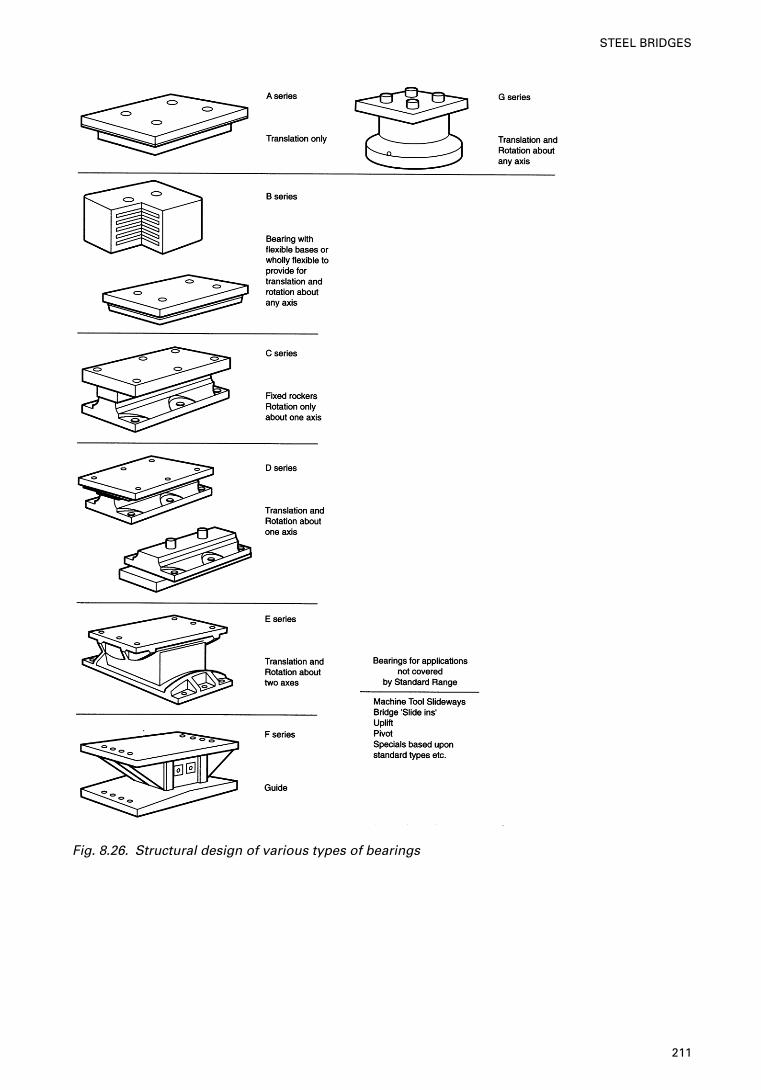
Fig. 8.26. Structural design of various types of bearings
211
STEEL BRIDGES
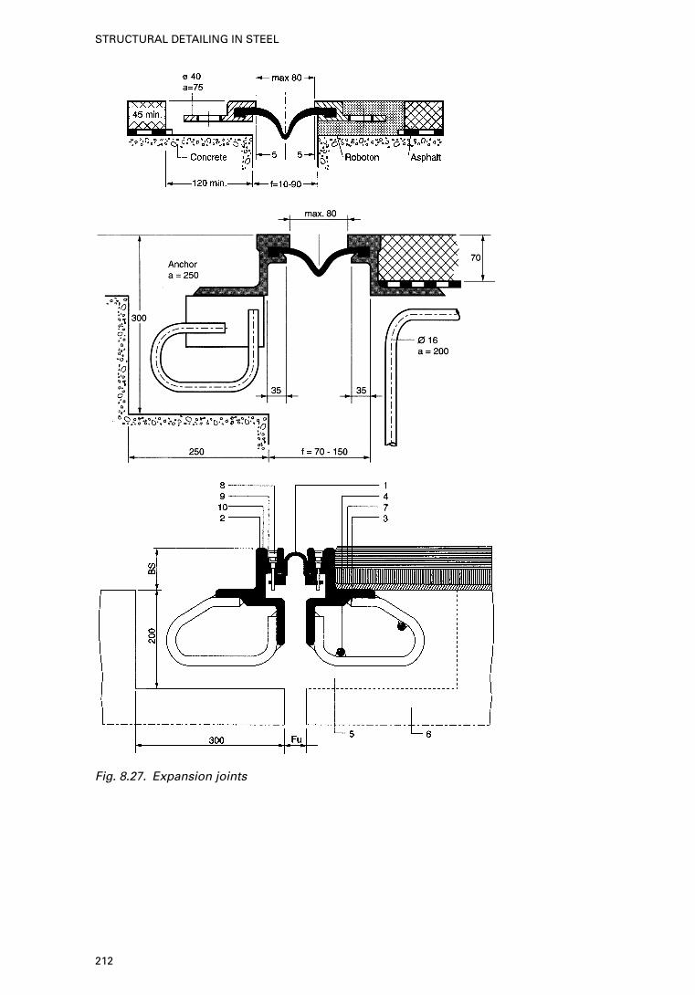
Fig. 8.27. Expansion joints
212
STRUCTURAL DETAILING IN STEEL
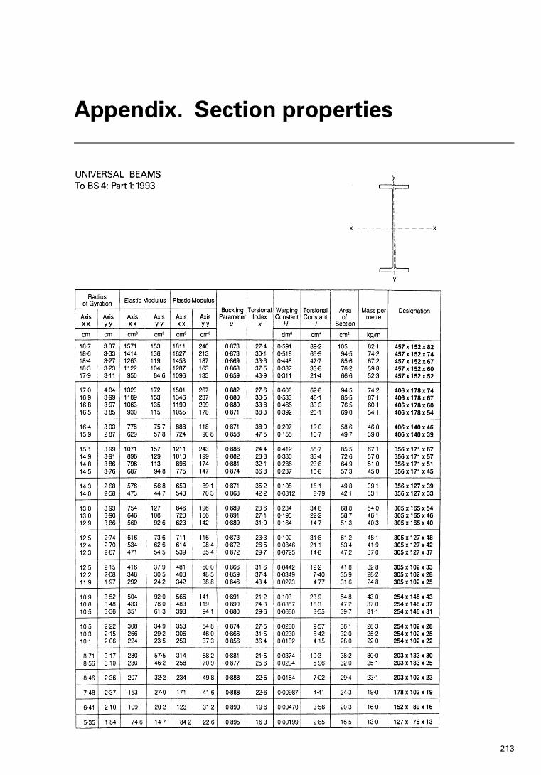
Appendix. Section properties
213
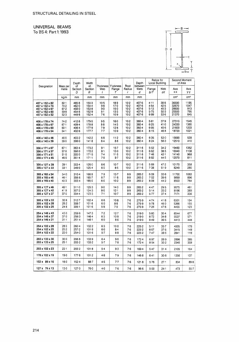
214
STRUCTURAL DETAILING IN STEEL
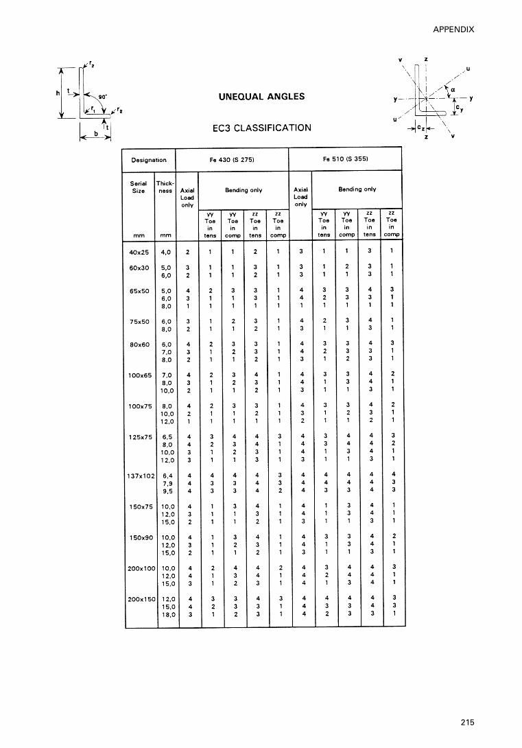
215
APPENDIX
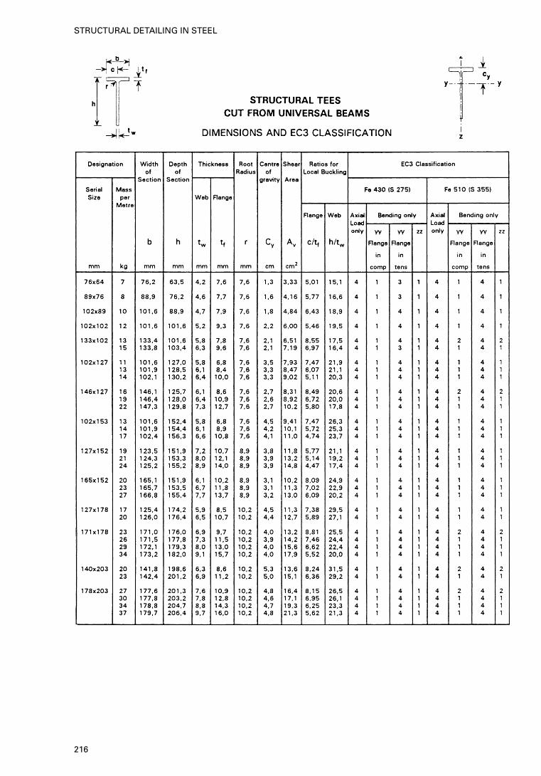
216
STRUCTURAL DETAILING IN STEEL
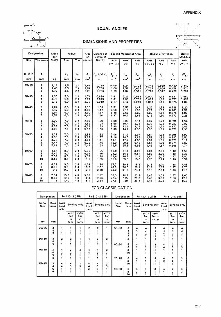
217
APPENDIX
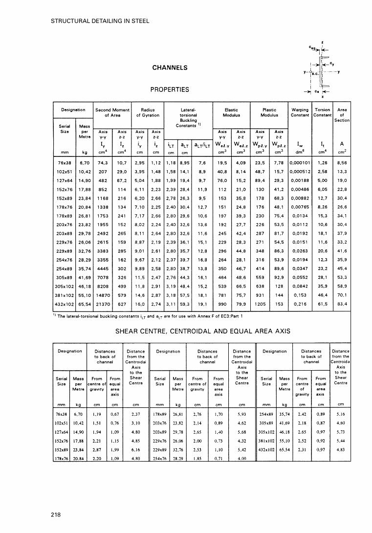
218
STRUCTURAL DETAILING IN STEEL
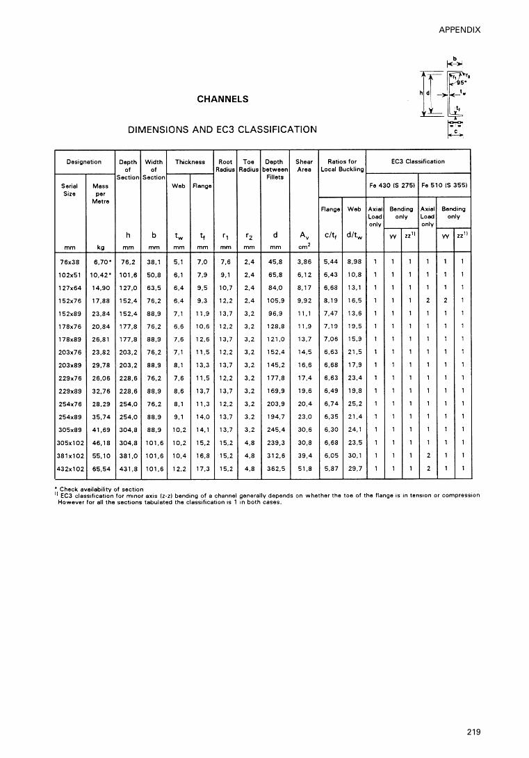
219
APPENDIX
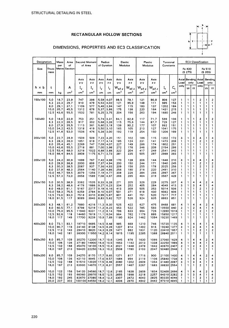
220
STRUCTURAL DETAILING IN STEEL
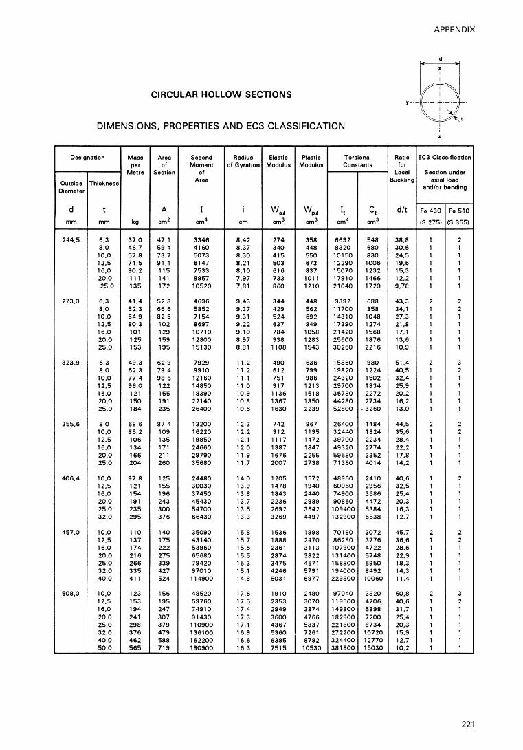
221
APPENDIX
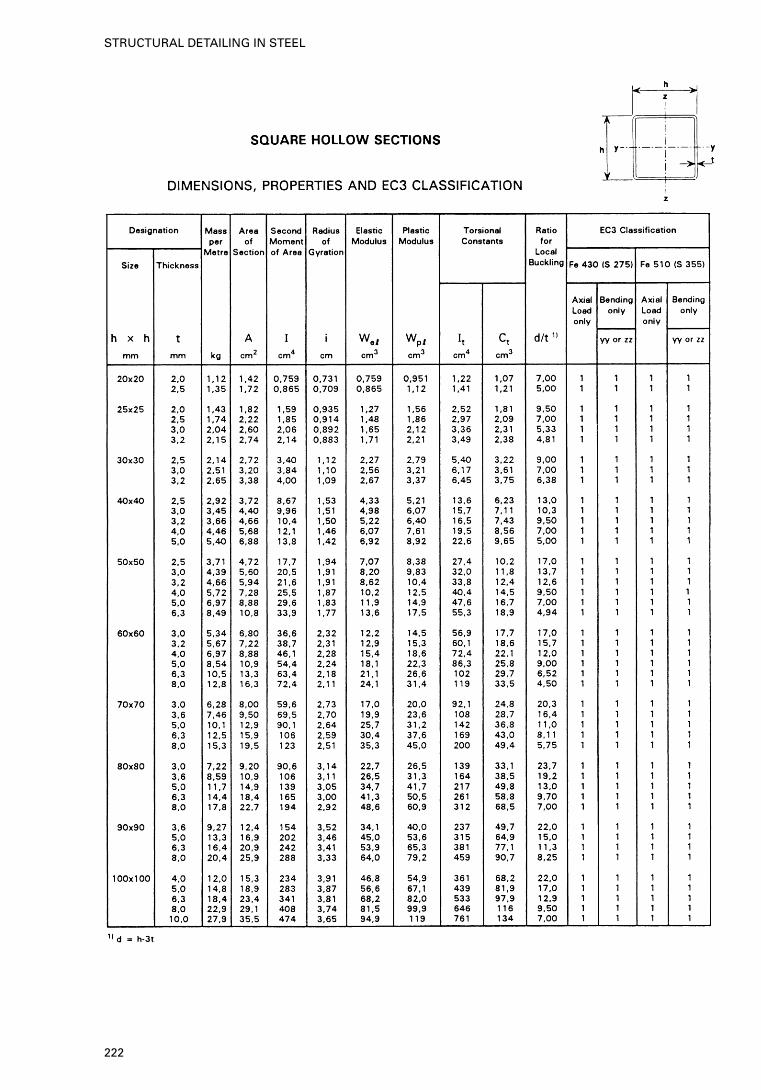
222
STRUCTURAL DETAILING IN STEEL
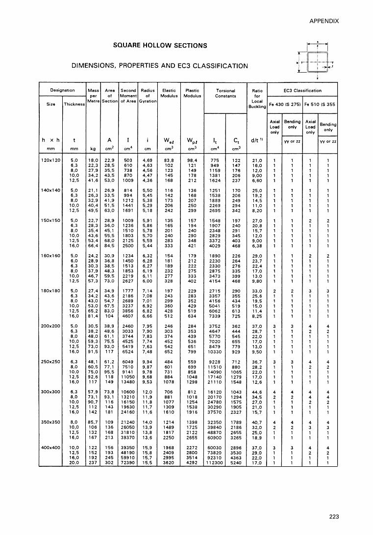
223
APPENDIX
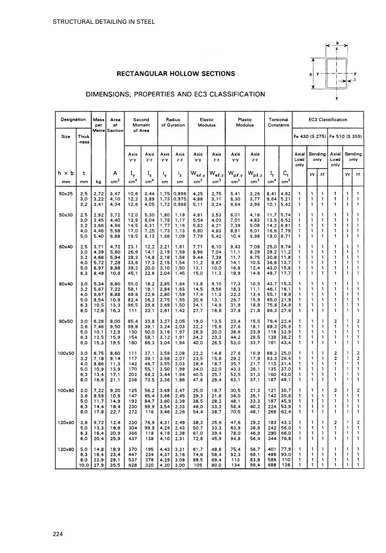
224
STRUCTURAL DETAILING IN STEEL
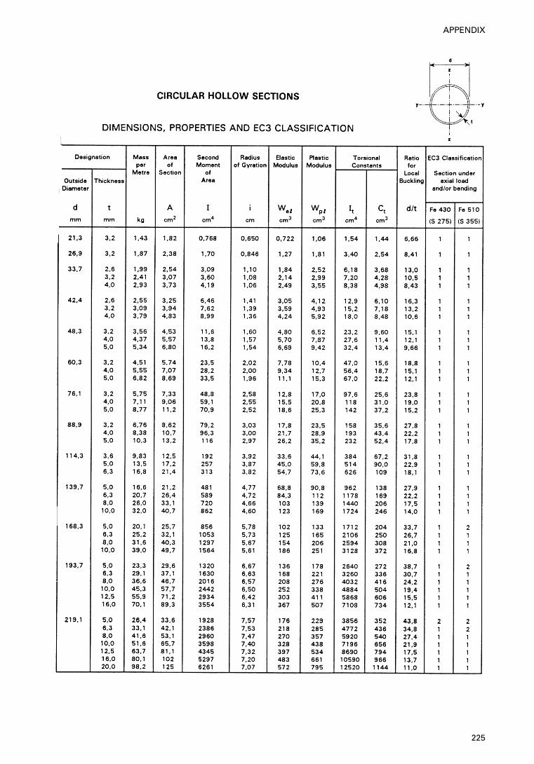
225
APPENDIX
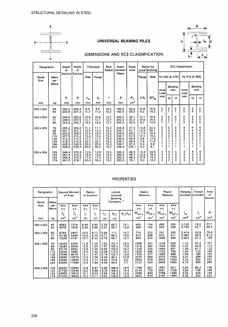
226
STRUCTURAL DETAILING IN STEEL
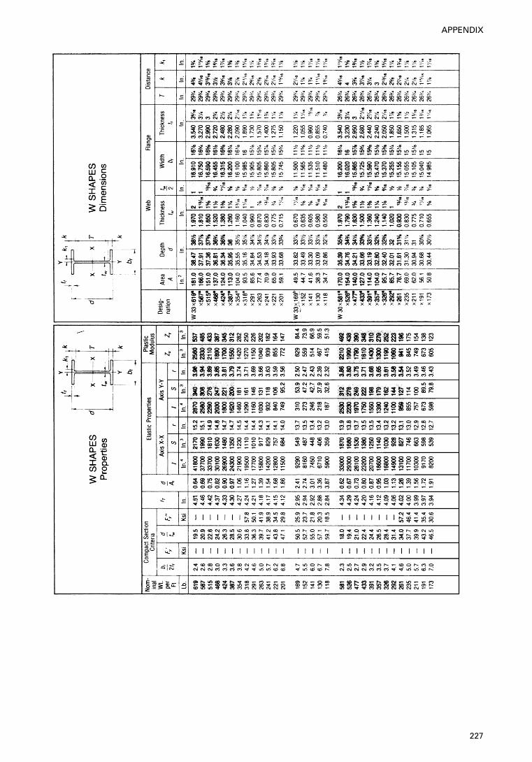
227
APPENDIX
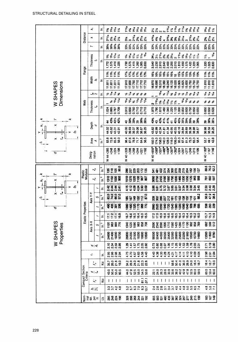
228
STRUCTURAL DETAILING IN STEEL
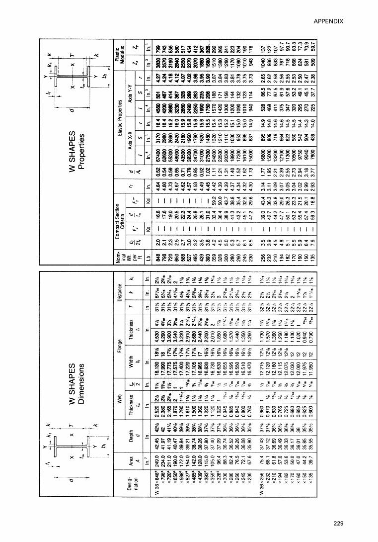
229
APPENDIX
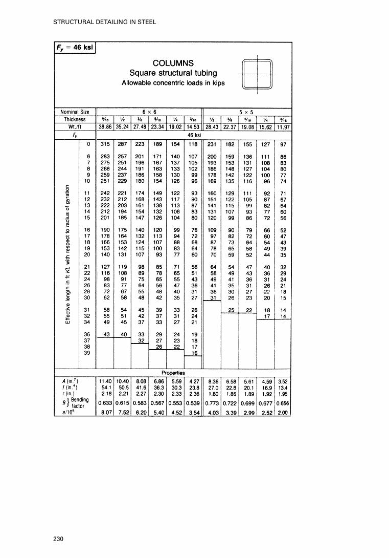
230
STRUCTURAL DETAILING IN STEEL
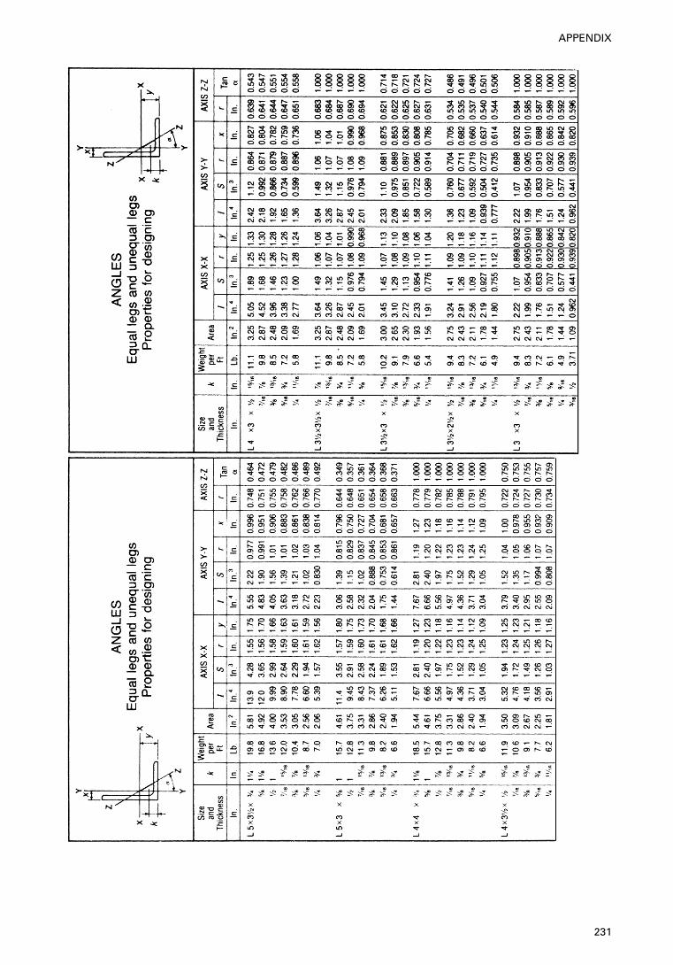
231
APPENDIX
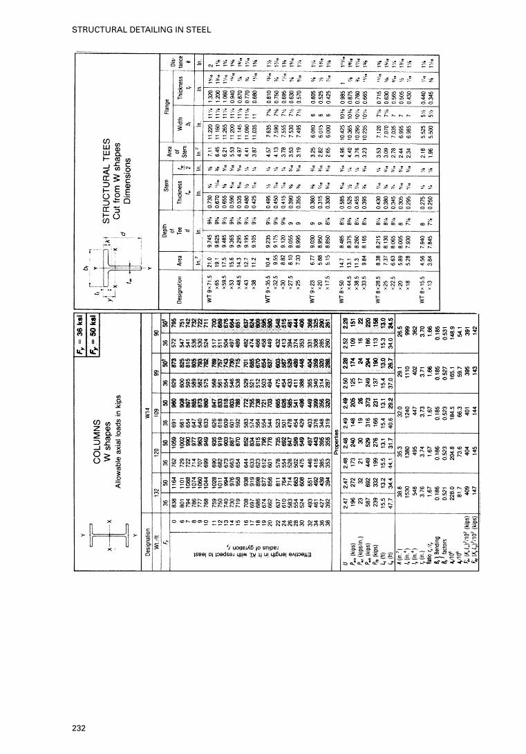
232
STRUCTURAL DETAILING IN STEEL
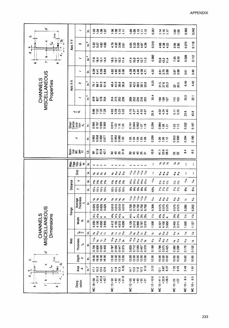
233
APPENDIX
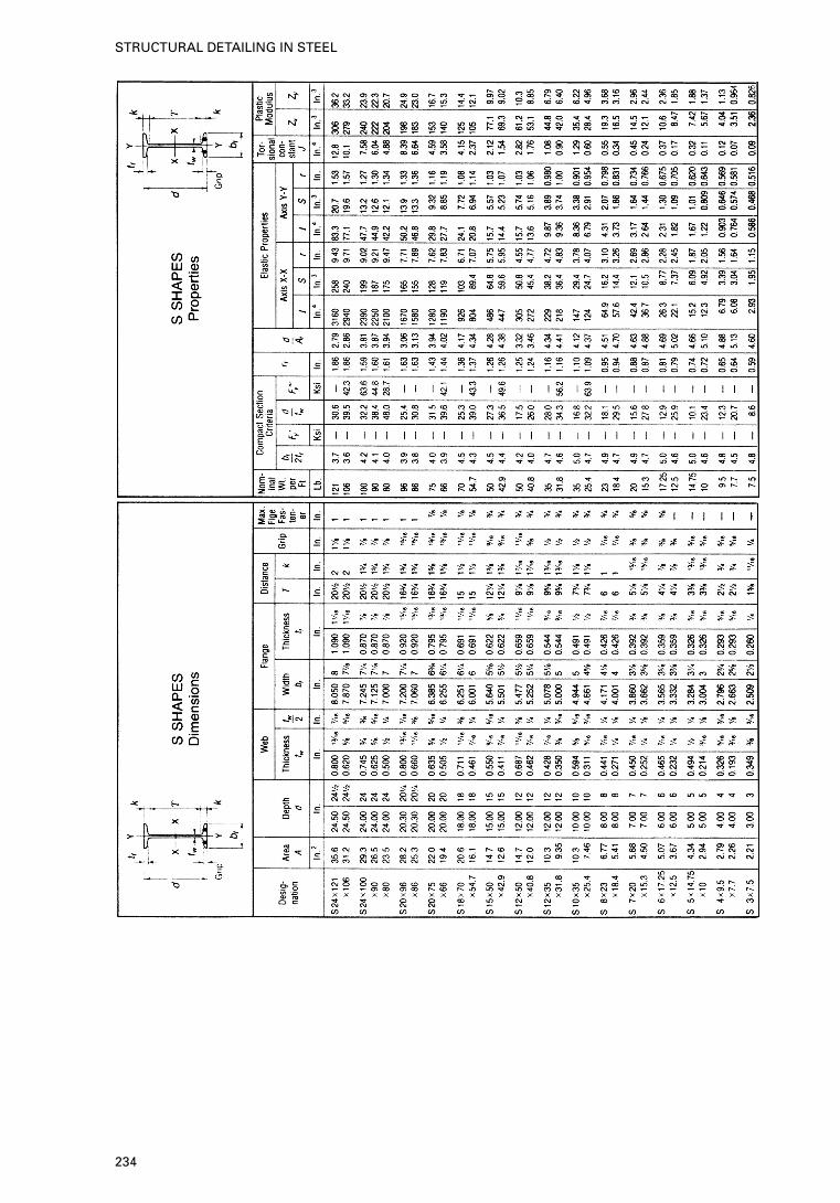
234
STRUCTURAL DETAILING IN STEEL
Bibliography
Advisory Desk Note AD 097. Nominal base stiffness. Steel ConstructionToday, November 1991.
Bangash, M. Y. H. Phototype bridge structures: analysis and design. ThomasTelford, London, 1999. Prototype building structures: analysis and design.Thomas Telford, London, 1999.
Blodgett, O. W. Design of welded structures. James F. Lincoln Arc WeldingFoundation, USA, 1966.
Clark, A. B. and Coverman, S. H. Structural steelwork: limit state design.Chapman and Hall, London, 1987.
Davies, J. M. Plastic collapse of framed structures clad with corrugated steelsheeting. Proc. Instn. Civ. Engrs., Part II, Vol. 55, March 1973.
Davies, J. M. and Brown, B. A. Plastic design to BS 5950. Blackwell Science,Oxford.
Davies, J. M. et al. Realistic modelling of steel portal frame behaviour.Structural Engineer, 68, No. 1, 1990, 1–6.
Notes of guidance on the specification for highway works Part 6, Departmentof Transport, HMSO, 1986.
Departmental Standard BD7/81. Weathering steel for highway structures,Department of Transport, 1981
Engel, P. The testing and analysis of pitched roof portal frames. PhD thesis,University of Salford, July 1990.
Horne, M. R. and Morris, L. J. Plastic design of low-rise frames. ConstradoMonograph, William Collins, 1981.
Johnson, R. P. Composite structures of steel and concrete. Vol. 1: Beams,columns, frames, 1974; Vol. 2: Bridges, 1986, Blackwell Science, Oxford.
King, C. M. Plastic design of single-storey pitched-roof portal frames toEurocode 3. ASCOT: SCI, 1995.
Liu, T. C. H. Theoretical modelling of steel portal frame behaviour, PhDthesis, University of Manchester, October 1988.
Macleod, I. A. Guidelines for checking computer analysis of buildingstructures, CIRIA Technical Note 133, 1988.
Manual of steel construction, 18th edn, AISC, 1990. BS 5395: 1977 Code ofPractice for stairs.
Morris, L. J. and Plum, D, R, Structural steelwork design to BS 5950,Longmans Scientific and Technical, 1988.
O’Connor, C. Design of bridge superstructures. Wiley Interscience, New York,1971.
Safety in steel erection, ISBN 011 833 2417, HMSO, London, 1979.Steel Construction Institute. Steelwork Design Guide to BS 5950: Part 1: 1990,
Volume 1 — Section properties and member capacities, 3rd edn, 1992.The Steel Construction Institute/The British Constructional Steelwork Asso-
ciation. Joints in steel construction — moment connections, publication No.207/95, 1995.
Structural fasteners and their applications, BCSA,1978.Structural steelwork handbook. Properties and safe load tables. BCSA/
Constrado (now SCI), 1978.
235
BIBLIOGRAPHY

Troisky, M. S. Orthotropic bridge theory and design. James F. Lincoln ArcWelding Foundation, USA, 1968.
Welding Research Council and American Society of Civil Engineers. Plasticdesign in steel: guide and commentary. 2nd edn, ASCE, New York, 1971.
236
STRUCTURAL DETAILING IN STEEL
Part 9: 1994 Code of Practice for stressed
skin design
British Standards and other Standards
British Standards
BS 4: Part 1: 1980 Specification for hot-rolled sections.Part 2: 1975 Hollow sections.Part 4: 1972 Equal and unequal angles.
BS 639: 1976 Covered electrodes for the manual metal arc welding ofcarbon manganese steels.
BS 3429: 1961 Specification for the sizes of drawing sheets.BS 3692: 1967 ISO metric precision hexagon bolts, screws and nuts.BS 4165: 1984 Specification for electrode wires and fluxes for the submerged
arc welding of carbon steel and medium tensile steels.BS 4232: 1967 Surface finish of blast-cleaned steel painting.BS 4320: 1968 Metal washers for general engineering purposes. Metric
series.BS 4360: 1986 Weldable structural steels.BS 4395: High strength friction grip bolts and associated nuts and washers for
structural engineering.Part 1: 1969 General grade.Part 2: 1969 Higher grade.Part 3: 1973 Higher grade (waisted shank).
BS 4604: The use of high-strength friction-grip bolts in structural steelwork.Part 1: 1970 General grade.Part 2: 1970 Higher grade.Part 3: 1973 Higher grade (waisted shank).
BS 5135: 1984 Specification for metal-arc welding of carbon and carbon-manganese steels.
BS 5400: Steel, concrete and composite bridges.Part 1: 1978 General statement.Part 2: 1978 Specification for loads.Part 3: 1982 Code of practice for the design of steel bridges.Part 4: 1984 Code of practice for design of concrete bridges.Part 5: 1979 Code of practice for design of composite bridges.Part 6: 1980 Specification for materials and workmanship, steel.Part 7: 1978 Specification for materials and workmanship, concrete,reinforcement and pre-stressing tendons.
237
STANDARDS
Part 8: 1978 Recommendations for materials and workmanship,concrete, reinforcement and pre-stressing tendons.Part 9: 1980 Bridge bearings.Part 10: 1980 Code of Practice for fatigue.
BS 5493: 1977 Code of Practice for protective coating of iron and steelstructures against corrosion.
BS 5950: Structural use of steelwork in building.Part 1: 1985 Code of Practice for design in simple and continuousconstruction in hot rolled sections.Part 2: 1985 Specification for materials, fabrication and erection:hot-rolled sections.Part 4: 1982 Code of Practice for the design of floors with profiledsteel sheeting.
Steelwork design guide to BS 5950: Part 1: 1985.
Other standards
AISC specification for structural joints — allowable stress design specificationfor structural joints using ASTM A325 or ASTM A490 bolts, 1986.
AISC specification for structural steel buildings — allowable stress design andplastic design, 1989.
AISC QC Program, Quality Certification Program Description, 1990.AISC Code of Standard Practice, Code of standard practice for steel buildings
and bridges, 1992.ANSI/AWS D1, 1-81 Structural welding code, USA.
238
STRUCTURAL DETAILING IN STEEL
ASTM Standards
ASTM A36 Carbon Structural Steel, 1994a.ASTM A53 Pipe, Steel, Black and Hot-Dipped, Zinc-Coated Welded and
Seamless, 1993a.ASTM A325 Structural Bolts, Steel, Heat Treated, 120/105 ksi Minimum
Tensile Strength, 1994.ASTM A463 Steel Sheet, Aluminium-coated by the Hot-Dip Process,
1994.ASTM A490 Heat-Treated Steel Structural Bolts, 150 ksi Minimum 1993.ASTM A500 Cold-Formed Welded and Seamless Carbon Steel Structural
Tubing in Rounds and Shapes, 1993.ASTM A501 Hot-Formed Welded and Seamless Carbon Steel Structural
Tubing, 1993.ASTM A529 High-Strength Carbon-Manganese Steel of Structural Qual-
ity, 1994.ASTM A570 Steel, Sheet and Strip, Carbon, Hot-Rolled Structural Quality,
1992; R1993.ASTM A572 High-Strength Low-Alloy Columbium-Vanadium Structural
Steel 1994b.ASTM A588 High-Strength Low-Alloy Structural Steel with 50 ksi
(345 MPa) Minimum Yield Point to 4 in. (100 mm) Thick,1994.
ASTM A606 Steel, Sheet and Strip, High-Strength, Low-Alloy, Hot-Rolledand Cold-Rolled with Improved Atmospheric CorrosionResistance, 1991a; R1993.
ASTM A607 Steel, Sheet and Strip, High-Strength, Low-Alloy, Colum-bium or Vanadium, or Both, Hot-Rolled and Cold-Rolled,1992a.
ASTM A653 Steel Sheet, Zinc-Coated (Galvanized) or Zinc-Iron Alloy-Coated (Galvannealed) by the Hot-Dip Process, 1994.
ASTM A792 Steel Sheet, 55% Aluminium-Zinc Alloy-Coated by the Hot-Dip Process, General Requirements, 1993a.
ASTM B117 Salt Spray (Fog) Testing Apparatus, 1994.ASTM B209 Aluminium and Aluminium-Alloy Sheet and Plate, 1993.ASTM C518 Steady-State Heat Flux Measurements and Thermal Trans-
mission Properties by Means of the Heat Flow MeterApparatus, 1991.
ASTM C553 Mineral Fiber Blanket Thermal Insulation for Commercialand Industrial Applications, 1992.
ASTM C612 Mineral Fiber Blanket Thermal Insulation, 1993.ASTM C1289 Bitumen Content, 1986, R1993.ASTM D522 Mandrel Bend Test of Attached Organic Coatings, 1993a.ASTM D714 Evaluating Degree of Blistering of Paints, R1994.ASTM D968 Abrasion Resistance of Organic Coatings by Falling Abra-
sive, 1993.ASTM D1308 Effect of Household Chemicals on Clear and Pigmented
Organic Finishes, 1987; R1993.
239
STANDARDS
ASTM D1654 Evaluation of Painted or Coated Specimens Subjected toCorrosive Environments, 1992.
ASTM D2244 Calculation of Color Differences from Instrumentally Meas-ured Color Coordinates, 1993.
ASTM D2247 Testing Water Resistance of Coatings in 100 Percent RelativeHumidity, 1994.
ASTM D2794 Resting of Organic Coatings to the Effects of RapidDeformation (Impact), 1994.
ASTM D3359 Measuring Adhesion by Tape Test, 1995.ASTM D3841 Glass-Fiber-Reinforced Polyester Plastic Panels, 1992.ASTM D4214 Evaluating the Degree of Chalking of Exterior Paint Films,
1989.ASTM D4397 Polyethylene Sheeting for Construction, Industrial and Agri-
cultural Applications, 1991.ASTM E84 Surface Burning Characteristics of Building Materials.ASTM E96 Water Vapour Transmission of Materials, 1994.ASTM E1042 Acoustically Absorptive Materials Applied by Trowel or
Spray, 1992.ASTM G23 Operating Light-Exposure Apparatus (Carbon-Arc Type)
With and Without Water for Exposure of Non-metallicMaterials, 1995.
240
STRUCTURAL DETAILING IN STEEL


![Bangash - Structural Details in Concrete [Blackwell Scientific 1992]](https://img.dokumen.tips/doc/110x75/563db78f550346aa9a8c30fb/bangash-structural-details-in-concrete-blackwell-scientific-1992-568a123095619.jpg)


![Bangash - Structural Details In Concrete [Blackwell Scientific 1992].pdf](https://img.dokumen.tips/doc/110x75/563db796550346aa9a8c7004/bangash-structural-details-in-concrete-blackwell-scientific-1992pdf-568a8b4f95ca0.jpg)