Embed Size (px)
DESCRIPTION
Myford Dividing Head Attachment Manual
Citation preview
MTIORD1495 DIVIDING ATTACIIMEM
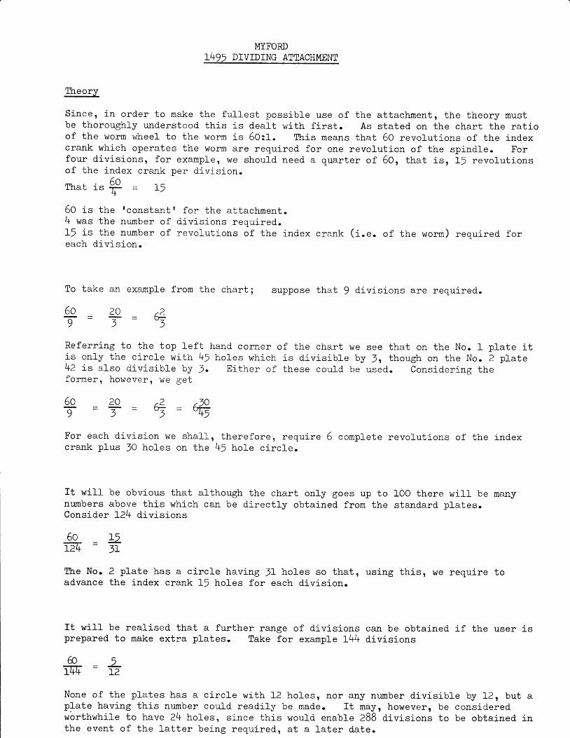
Theory
Since, J-n order to make the fullest possible use of the attachnent, the theory nustbe thoroughly understood this is deaft with first. As stated on the chart the ratioof the worm wheel to the worm is 60:1. Ttris neals ttiat 50 revol-utions of the indexcrank which operates the wonn are required for one revolution of the spindle. Forfour divisions, for example, we should need a quarter of 50, that is, 1! revolutionsof the index crark per division.
A^Ihat is fr = 15.t
50 is ttre rconstantt for the attachnent.4 was the nunber of divisions required.lJ is the nunber of revolutions of the index c rank (i.e. of the worm) required foreach division.
To take an example f rom the chart ; suppose that 9 divisions are required.
6o =9
a v
T=r 23
Referr ing to the top le f tis only the ci-rc1e with 45l . a+? is a lso d iv is ib le by 3.former, however , we get
hand corner of the chart weho les wh ich is d iv is ib le by
E i ther o f these cou ld be
see that on the No. t plate i t3, though on the No. 2 plate
used. Consider inE the
.10r. 2"3
5o9
207
For each div is ion we shal l ,crank plus JO hol-es on the
t h e r e f o r e , r e q u i r e45 ho le c i rc le .
complete revolut ions of the index
It will be obvious that although the chart only goes up to l-OO there wiII be manynumbers above this which can be direct ly obtained from the stand.ard plates.Consider L24 divisions
TLre No. 2 plate 'has a circle having JI holes so that, using this r we require toadvance the index crank 15 holes for each dj-vision.
It will be realised that a further rarlge of divisions carr be obtained if the user isprepared to make extra plates. Take for exanple I44 divisions
5o L5Tfr=3r
&5 =1+4 12
None of the plates has a c i rc le wi th L2plate having this number could readilyworthwhi le to have 24 holes, s ince thisthe event o f the la t te r be ing requ i red ,
holes, nor any number div is ib le by L2, but abe made. I t i layr however, be considered
would enable 288 div is ions to be obtained ina t a la te r da te .
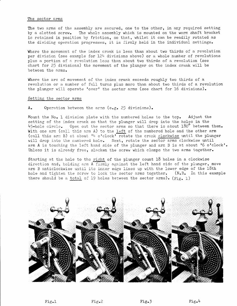
The sector arms
The two arns of the assembly are secured! one to the other, in any required settingby a slotted screw. The whole assenbly which is noulted on the worm shaft bracketis retained in posltion by friction, so that, whilst it can be readily rotated asthe di"viding operation progxesses, it is fi-rmly held in the inCividual settings.
Where the rnovement of the index crank is less thal about two thi-rds of a revol-utionper division (see exanple for 124 divisions above) or a whole nunber of revofutionsplus a portion of a revol-ution less than about two thirds of a revolution (seechart for 2l divisions) the movenent of the phurger on the lndex crank will bebetween the arms.
Where the arc of movementrevo lu t ion or a number o fthe plunger wi l l operate
Set t ing the sec tor a rms
A. Opera t ion be tween
ho le and t igh ten the screwthere shou ld be a to ta l o f
/t n e a r m s \ e . 8 . 2 5 d i v i s i o n s ) .
Morurt the No. I division plate wi-th the numbered holes to the top. Adjust thesettlng of the index crank so that the plunger wi}l drop into the holes in the45-hol-e circle. Open out the sector arms so that there is about 1E0- between them.1'/ith one arm (caII this arm a) to tne }eft of the numbered hole and the other arn(call- this arn B) at about 14 o'cfockt-rotate the crank clockwise untj-l the pl-ungerwill drop into the nurnbered ho1e. Next, rotate the secffi-artns clockwise tmtilarn A is touching the le f t hand s id.e of the p lunger and arm B is at about 15 orc lockt .Unless it is already free, sl-acken the screw which clamps the two arms together.
Starting at the hol-e to the g!g
B. Operat ion over the arms (e.g. 15 d iv is ions) .
Open up the sector arns so that there is about 12Oo between them. Adjust thesetting of the index crank so that the plunger will drop into the holes of the.,2-t1o]'e circfe. -(No. t plate). With arrn B to the right of the numbered hol-es andarrn A at about 18 orclockr rotate the crank cloc -wisE-TI-[ the plunger will dropinto the nunbered ho1e. Next rotate the seffii arms anticlockwise so that arm Bw h i c h i s t o t h e r i g h t o f t h e p 1 u n g e r i s t o u c h 1 n g i t ( s - t i r r o n t n e r l g h t h a a d s i d e ) .
Starting at the hol-e to the left of the plunger cor.nt 8 (i.e. 32 - 24) holes j-n alanticlockwise direction and, holdlng arm B firrnly against the right hald side of thepfunger, move arm A upwards, in a clockwise direction until its upper edge lines upwith the lower edge of the required hol-e and tighten the screw to lock the sectorarms together (N.B. In thi.s exampl- e there wil-l be a total- of ! holes between thesector arrns ) . (F ig. 4)
MountinR the attachment.
Where circumstances permit and both sfides are availabfe it will generalfy be fouldpreferabl-e to use the plain vertical slide 67/f as thj-s wil-l give greater rigidity.In addition, the maximun height of attachrnent splndle above the headstock spindle isslight1y greater than on the swivelling slid,e 68/2.
l{hen working with the axis of the attachment spi-ndle parallel to the axis of theheadstock spindle it will generally be preferable to have the attachment spindle atthe same height as the headstock spindle, thus working on the horizontal centre fine.
ldhen using a cutter on an arbor between centres, with the axes of dividing attachnentand headstock spindles at right angles one to the other, if the sun of the radli ofcutter and work exceeds 2.I/8tt (e.g. a 2rr dia, cutter and a 21tt d.ia. component) thedividing attachment nay be raised z.I/Btt by using No. 3O/OLI raLsi.ng block for ML7and Super 7 lathes. Where this is not available, or if when using i-t, the sum ofthe radi i exceeds { t t , i t w i l f be necessary to increase the centre d is tance betweencutter and work i"n some other way.
fhis may be achieved by repositioning the key in the back of the spj-nd1e bxacket byfitting i-t in to the vertj-cal slot and rotating the table of the swivelling slide58/Z ana rnounting the attachment wlth the slide so swivelled that the attachmentspj-ndle 1s looking up at an angle. The axis of the feedscrew of the miUlng slidew1ll- then be paral1e1 to the axis of the spi"ndle of the dividing attachmen';. (Seedrawing on sheet 5.25468). Ttre appro'ximate setting for height may be made withboth cutter and workpiece in position by rotatlng the sfide table and dividingattachment ald sinu-l-taneously advancing or withdrawing the cross slide, and, bymeans of its feed screw, adjusting the positlon of the milling slide tab1e.
The feed of the workpiece across the cutter will be by rneans of the feed screw ofthe swivelling sl-ide, the depth of cut wifl be controlled by the cross sl-ide feedscrew. It will be noted, however, that the depth of cut actr.rally applied will beless than the movement of the cross sl-lde and that the relationship will vary withd i f f 6 ' i h m r h d l ^ c
The amount of cross sLide novernent for any required depth of cut nay be cal-cu-l-atedby using the formula
WhereSinA
f = amount cross s l ide i -s toc = requi-red depth of cutA = angle of incl i -nat ion of
be moved
sl idc and div id ing at tachment
Reference to t r igonometr i -c tables wi l l show that an incl j -nat ion of 30" to thehor izontal should be chosen whenever possible s ince the amount of movennent of thecross s l ide w i l l be exac t lv tw ice the reou i red depth o f cu t .
a
Uhere the workpiece is suitabfe it should be nounted in a chuck or No. 1OJl co11etwith 14rB nosepiece. It is not advised. that the work be normted between cen!r:e6.Ttie outboard support is not intended for this purpose. Conponents which are boredshoul-d be mormted on a stub arbor nachined to suit. This in turn nay be mounted ina chuck, in the No. 1Ol1 coll-et or it nay have a No. 2 H.T. shalk and be mormteddirect i"n the taper in the spindle of the attachment.
TLre overarm and outboard support centre.
If the component has a centre at i ts outer endsuch a centre, the outboard centre may be used
Operatlon indexing.
Withdraw the plunger, rotateplus 24 holes, that is justcrank rotate the sector armsplunAer.
As am exanple of use, assume the cutting of the teeth on a 25 tooth spur gear.
l ' lount the cutter on ai arbor between centres (or held ln the chuck, with tailstocksupport ) .
ount the vertical slide on to the fathe cross slide, the dividing attachnent on toit ald nount the work piece.
Centralise the work piece to the cutter ald set for height so that the cutter justtouches the periphery of the work piece.
Fit the number I d iv is ion plate and set the index crank and the sector arms asdescr ibed as A on sheet 2146F.
Set for the required depth of cut.
Rotate the index crank clockwlse until the phmger drops into the nunbered hole.(N.B. It rnay be found convenient when rotating the index crank to stop just shortof the required hol-e and then to tap the index crark round until the plunger drop6i n ) .
ldake the first cut.
Check that the sector arms are in their conect position (arm A touching the lefthaad side of the plunger) and wj.thdraw the plunger. Rotate the knob to a1low theshallow notch to engage with the stop peg. Now rotate the index crank clockwisetwo complete revoluti.ons plus 18 hol-es that is up to arn B ald aliow the plunger todrop in to the hole in the index plate. (S.2545B Fig.Z)
Cut the second tooth.
Rotate the sector arms cl"ockwise so that arm A is again touching the plunger.(tr,ig.r)
Uithdraw the pluurger and i-ndex as before.
When opera t j -ng over the sec tor a rms (e .g .16 d iv is i -ons , see sheet 5 .2545C) , themovements of the index crank wi l l agaj-n be in a c lockwise direct ion, though thist ime the sector arns wi l l be moved aat ic lockwise. However, &t the connencement,with the plunger in the nlmbered holf,arm B wil l be touching the right hand sideof the ph:nger, whereas arm A wil l be at f nire o t clock | . fhe movement of theindex crank wil-l be : -
or is mount ed on a stub arbor withfor addit ional support.
the index crank clockwise three complete revolut ionsover arm A. Before the next movement of the index
anticlockwise so that arm B is in contact with the
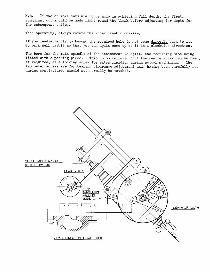
N.B. I f two or more cuts are to be mad.e in achieving ful l depth, the f i rst ,roughingt cut should be made right ror,md the blank before adjusting for depth forthe subsequent cut (s) .
Then operating, always rotate the index crank clockwise.
:If you inadvertently go beyond the requir.ed hole do not cone directly baik to it.Go back well pa*it so that you can again cone up to it in a clockwise direction.
The bore for the nain spindle of the attachnent is split, the resuJ.ting slot beingfitted with a packing piece. $ris is so relieved that the centre screw ca.rr be used,if required, as a locking screw for extra rigidity during actual nachining. Thetr"o outer screwe are for bearlng cleara::ce adjustment ald, having been carefulJ-y setduring naaufacture, should not nornally be touched.
6 8 1 2SWIVELLINGMILL ING
DEPTH OF TOOTH
VIEW IN DIRECTION OF TAILSTOCK
.Sils!@.
No adjustments should be necessary r"mt i l the at taohment has had an appreciable
amount of use. fhere are, however, four which can be made.
Should the spindle bear ing c learance eventual ly need adjustment, i t wi l - I benecessary to remove and thin the packing pi-ecen
Erd float iI the spindle can be eliminated by adjusting the collar at the rear endof the spi-ndle. Ihis is threaded (right hand) on to the spindle and is securedby neans of a grub screw which must be rel-eased for the adjustnent to be made aldretightened afterwards.
Backl-ash between wonn arrd wormwheel car] be el-iminated by xel-easing the hexagon headscrews vhich secure the worm bracket to the nain body of the attachnent andloweri.ng the bracket. Note that the bracket is keyed to the body.
The position of the phurger in the index crank can be adjusted if, with the plungerlocated so that the stral-Low notch is engaged with the stop peg, the ph.urger willnot pass over the sector arns (aflow about IA6n, 1.5 nn, clearance). To adjust,release the socket set screw in the end of the pl-unger knob, release the plunger5in order to reduce the l-oad on the spring, but hold the knob so that the plunger isnot fully engaged with the dividing plate and screw the plunger into the knob therequisite anormt. Re-tighten the socket set screw to lock the plunger in positlonin the knob.
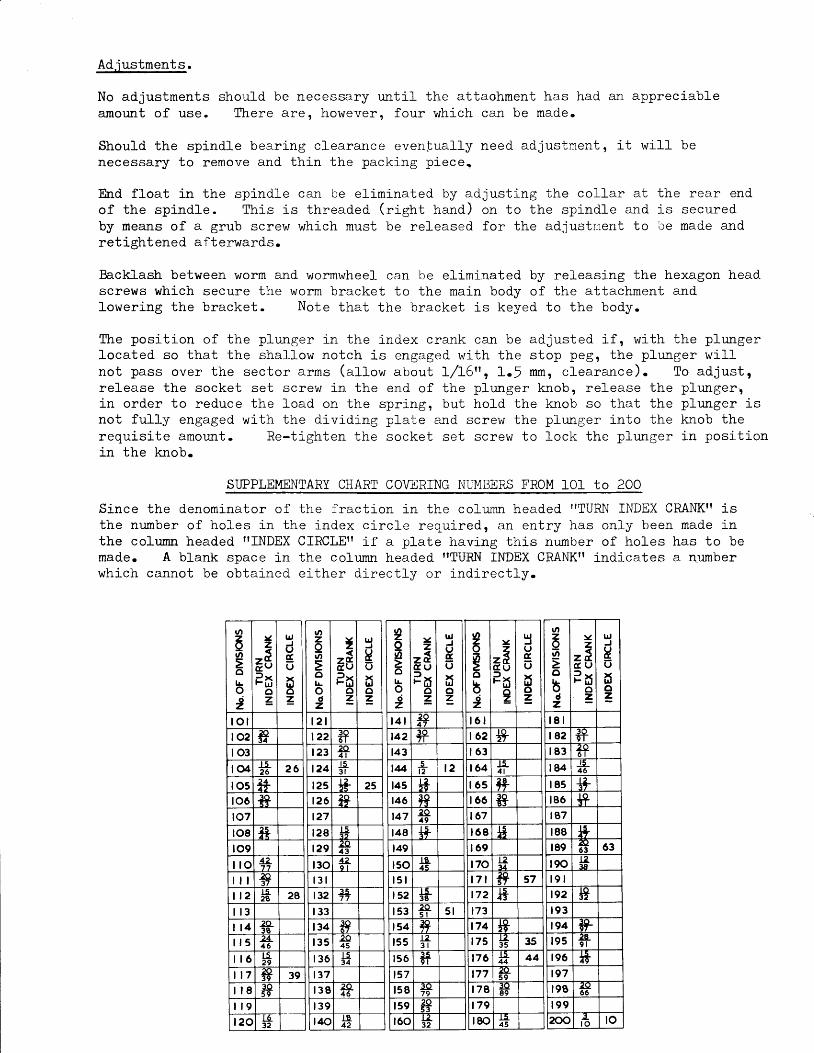
SUPPLEMENTARY 0HART COVERTNG NUI4BERS FROM l-01 to 200
Si-nce the denorni-nator of the fracti-on in the colurnn headed ilTURN INDEX CRANKfT isthe number of holes in the index ci-rc le required, an entry has only been made inthe colunn headed ff INDEX CIRCLE| T if a plate havi-ng this number of holes has to bemade. A blank space in the column headed TTTURN INDEX CRANK|T indicates a numberwh ich cannot be ob ta ined e i ther d i rec t l y o r ind i rec t l y .
o
6l/l
Eo|lo2
Yz
at,Pr
oz
tr,,JUd,(J
xlrJoz
t o ll 0 2l 0 3
l 0 4t 52 6 2 6
t 0 5 1+l 0 6 t+t07t08t09i lo 1Z
7 7
i l l 2937
i l 2 t528 2A
l 1 3l t 4i l 5 4L
4 6
i l 6 t52 9
t t 7 29.39 39
i l 8 3A5 9
I t 9
t 2 0 L0-32
t,l)zavl
ol!odz
,
&t,Pr
o=
lrJ
EUx!Jo=
t 2 l122 t?t 2 3 :9'
4 l
124 l5_3 l
t2s *+ 25t 2 6 1*t27t 2 8t 2 9t30 12
9 l
l 3 l
t 32 3 57 7
1 3 3
4341 3 5 i/L)
4 5
1 3 6 t534
t37t 3 8 20
4 6
t 3 9t40 rn
12
2I!4
o|!
odz
Yz
ze,C U35
oz
trJJuguxr.uoz_
t 4 l z4 '
t42
143
l4 l_t 2 , 2
145 t+t46
t47 :e1 9
148 ++t49
tsot s lt52 IL
38
t 5 3 5 lt54 *t 5 5 t2
3 l
t 5 6 15'9 l
t57t 5 8 t9
79t 59160 ,A
32
v)6goLo2
Y
=3c uP5
oz
trJ
Ucu
to=
t 6 l1 6 2
t 6 3
164 LiL4 l
t 6 s E+t 6 6 i?167
t 6 8
1 6 9
t7a. t2a4
t 7 a :a5 7 57
t72 F473
174175 IZ
35 35t76 t:L
44 44
t 77 ea-5 9
t 7 8
t79
t80 .L;L4 5
t/)zI|n
o
bdz
Yz
z c td u3r
oz
tr,
HU
toz
t 8 l, 8 2 3 0
9 l
t 8 3 296 l
184 _tL4 6
t 8 5 ++1 8 6
187
t 8 8 t+t89 4
63 63
t90l 9 lt92 *?t 9 3
194 8rt 95 izL
9 l
r96 It49
, 9 7t 9 8 z9
6 6
1 9 9200 .iL
l o to
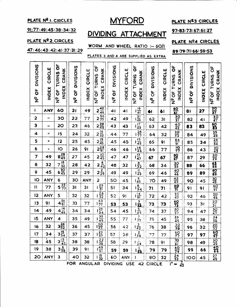
PLATE Ng I. CIRCLES
9l :77 : 49 2 45 :38 z 34', 32
MYFORDprvlgJNc AITACHMENTIYORM AND WHEEL RATIO :- 6O/t
PLATES 3 ANp 4 ARE S-UplL.lEp AS EXTRA
I r t t t 7 7
45 45r 5
l o 5
46 46 rfl47 47 rf,48 32
Ar:il
49 49 r*50 45
9t 4 5
5 l 34 r$52 9 l r$53 53 rt54 45 r*
puere xeg ctncues
97"83:73:67:61:27
PLATE N94 CIRCLES
lzzlFIi---"--*'-T
_ l * L
73 i_-_-':.:*.*l
6 0 i_E_ i33 7 7
34 34 rfl35 4g . 3 5l ae
36 45 . 3 0r 4 5
37 37 r$38 38 , ? 2
' q g
39 9 l rfi40 32 r$
i s6 i4? i l f f i i[ ; ;- i- ; ;- i
- '3-I sz i gs i r e ir-- ----+-- - --:-5 9-ll l i ; i
LsB i ;s i l ; * IT--r-_-T-___"-r-99 -r t2 ,--r iB Jf-----t.- ----1-
Lio L11Y_t_;
ozIa
olr-o
Otz
u,Juguxu,o=
lr.O yoz7#5uFx
hHv zOtz
I ANY 60
2 t 30
3 l a 20
4 tt r5
5 tl l 2
6 a l rO
7 a9 8i3I 32 7
"Y,9 45 6Hto ANY 6
l l 77 s#t2 ANY 5
r3 9 l +#l 4 49 af,t5 ANY 4
t6 32 3#t7 34 3Htg
t-
45 a l 5Y 1 . 1
r9 38 r$20 ANY 3
v,zoa
a|!
oolz
lr,J(Jg(,
xu.,6z
tLc ) Y
z2SguF } (
hH\ J Z
Olz
2 l 4g 2*
22 77 ^ 5 6zTz
23 46 ^ 2 8447
24 32 . l t4 3 2
25 45 - l gc7a
26 9t 2+F27 aS 2E28 42 zk29 29 2L
30 ANY 2
3 l 3t rS32 32 ,19t 3 2
i _ _ | 6 3
tnzII=olr-o
Olz
|!
oyr A Z;f r c5uF ) <tr- tf,- dY - ,
o t G<-
trtJUcoxrr,oz
rS2 l
49 l 4 e
rft
Qzo6:otLo
o|z
trtJ(,&,oxlr,az
l!O y
ez,G & ,
5uFx
bHO r =z
6l 6t606 t
62 3 l3 03 l
63 42 4 0n164 32 3-9
3 2
6s 9 l8 49 l
66 77 707 7
67 el 6067
68 34 3-934
69 46404
70 494 2Te
7 l
72
7t .
42.
19?t3 5a 3
az99zoll-oolz
lr,JIguxlr,,6=
ttO y
2e* c5uFx
$u_z
8 l 272t)fr
82 4 l3 04 t
83 83 608 3
84 493 54 9
85 342 434
86 43 30AT
87 292 0F
88 66 f 5G
89 89o()89
90 453045
9 l 9 l609 l
9A 4S3 0a3
!
i $ ?. F r t 3r 2 0
5 l
94 4V 3 04 7
95 3g? 43 B
96 32 20E
97 976 0D
98 49 304 9
99 664 Qrl
roo 45 2 7a-s
74 ,
73__12
45
s1r--3 6G
'7638
3 03 8
?? 776 0fr
78 9 l ze9 l
79 796 0're
80 32 2 451
CIRCLE IO-FOR ANGULAR DIVIDING USE 43