Embed Size (px)
Citation preview

I
1266 IEEE Transachons on Power Delivery, Vol. 5, No. 3, July 1990
MUTUAL COUPLING BETWEEN HORIZONTAL EARTH RETURN CONDUCXORS USING ACTUAL ROUTING PARAMFCERS
Eldon J. Rogers, L.S. Member, IEEE Consulting Electrical Engineer
John F. White, Member, IEEE Electrical Engineer
Bonneville Power Administration, MKTP P.O. Box 49 1 Vancouver, Washington, 98666
Formula for calculating mutual coupling between diversely routed. horizontal earth-return conductors used in the measurement of grounding system impedance is derived by using the complex ground plane concept used to rpprorimrro the Carson Equa&ion. Each potential conductor section is approximaled vi th equal length segments that parallel one of the current conductor sections. By repeating the parallel segmentation of each potential conductor section vi th each subsequent current conductor section and summing the segment mutua&, overall mutual betasen diversely routed conductors is obtained. This process is useful for calculating mutual to the potential conductor and for comparing possible potential conductor routings so as to minimite the overall mutual coupling.
KEYWORDS: EARTH RETURN, GROUNDING IMPEDANE, GROUNDING SYsMds
MUTUAL. IMPEDANCE, FINITE LENGTH CONDUCIURS,
IlI” Impedance measurements of grounding grids and grounding
systems require the use of temporarily installed conductors lying on ground, out-of-service transmission lines. or a combination of the two for connecting between the test grid and remote current and potential electrodCS I1 1.
Because of consrnints imposed by terrain, right-of-avays. roads, energized lines, and private property boundaries, it is unlikely, except for the smallest grids, that test leads (or, transmission lines) will be routed in either a parallel or angled simple straight line mmner. As described in Ref. (11, mutual coupling from the current carrying conductor to the conductor used to measure grounding potential rise could introduce significant errors in the grounding impedance measurement. Moreover, accuracy of measurement for low impedance grounding systems will require keeping the length of closely paralleled sections of current and potential conductors to a minimum.
Presently, mutual coupling from current to potential, for complex routing, can only be estimatsd from straight line approximations of their overall routing. In this paper we exbnd the segmented method for mutual coupling between angled conductors (using the complex ground return plane Ill). to diverse routings of horizontal conductors. Then. mutual impedance to the potential conductor, for a given routing of the current conductor, can be minimized by comparing mutual couplings for several accessible potential conductor routings.
Mutuds calculated vi th formulas presented here are accurate for the direct component between conductors. Overall mutuals, as affected by the image component, fall below Carson for the wider spacing of very long purllel conductors ill.
90 vCsli 057-0 FdRD A paper recommended and approved by t h e IEEE Power System Ins t runenta t ion 8 bleasure- .ients Committee of the Il:<E Power Engineering Society f o r presentat ion a t t h e IE’X/PrS 1990 . / in te r L i e e t h e , Atlanta , Georgia, February 4 - 8, 1990. I:anuscript submitted Au;ust 24, 1989 Fade ava i lab le f o r Tr in t in- January 16, 1990.
, REMOTE GRID
T E S T G R I D
LOC Ar Er hC LOC ai bi h p c 1 0 0 0 P I 0 0 0 c 2 0 0 10 P ; ! o - m o Q 400 1m 10 P4 0 500 0 c 5 4 0 0 1 m 10 P=) 300 500 0
c 7 m loo00 0 X,YZ coordinates in meter
C3 0 loo0 10 P3 300 -250 0
(& 700 10 P6 650 0
Formulas used to determine the mutual impedance from image conductors will require the evaluation of logarithms and square roots of complex numbers. -
Current and Potential conductor routings, shovn in Fig. 1. a c m o ” e s me averse rouungs or a out-or-service uansmiwon line connecting between the test grid and the remote grid which acts as the current electrode, and three possible routings of a test conductor, lying on the earth, which would connect between the test grid and a ground rod used as the remote potential electrode.
The relationship from any current section to each potential section may be parallel, angular and/or right angles. However, the mutual coupling analysis is Sided by using a XYZ coordinate system to defime change of direction locations of each current and potential section and their respective heights. The X-Y plane lies on the earth’s surface and coordinate 2 = h c or h p are current and potential conductor heights, respectively.
Equations (9.12 and I4 or 15,16 and 18) of the Appendix use the X-Y coordinstes that define the routing of current and potential conductors to determine the mutual impedance between horizontal earth return conductors. Equations (22.24 and 25) of the Appendix are used for angled conductors that can be defined by their length, horizontal angle, and when both originate from a common vertical axis.
U.S. Government work not protected by U.S. copyright. 0885-8977/90/0700-1266$01.00 0 1990 IEEE
1 1

I
-0.017-
1267
. ....... $ , ......1 , . ."." I " . . ' . " I '"".-I
IO 100 1000 10000 1M)OOo
EARTB RESISTIVITP. a m
Figure 2 -SON OF MUTUAL FOR TfIBEE NTIAL CONDUCTOR R OUTINGS OF FIG . I WITH AN
ANGLEDROUTING I = P 1 b P ( t o P ' j b P 6
I1 = p l ~ ~ ~ P 3 ~ @ t o p 6 111 = p1 to p;! p3 to p6
ANGLE = CUR: c2 to '&, POT: PI to p6 f = 60 Ib C = 10024.5 m P..= 2103 m e = 68'
MUTUAL IYPEDAN CE VERSUS POTENTIAL ROUTING S Mutual impedance between the tnrnsmission line current
conductor and each of the three potential conductor routings (I. 11. 111) of Fig. I are compared in Fig. 2 with a fictitious straight line angled routing from C2 to C6 for the current and from PI to P6 for the potential. Their mutual impedance components, RM and XM, calculated with Eqs. (9, 12 and 14 or 15, 16 and 18) of the Appendix are plotted in Fig. 2 against homogeneous earth resistivities of 1 to 100,000 A-m.
Potential conductor routings. I and 11. which lie closer to the current conductor have mutual components that are larger than for the fictitious angled routing. Routing 111 which is farthest from the current conductor has components that fall below the angled case. The magnitude of mutual impedance for routings I1 and I11 are reduced by the negative mutual coupling to the conductor section PI to P2. Although there are many constraints that limit conductor routings. routing selection for minimum mutual coupling can be aided by prior study.
RESISTIVITY
i4i 1 e - m u 2 1 0 a - m i43 100 2-m U 4 1 0 0 0 C--m 1 5 1 0 0 0 0 n - m U b l O 0 0 C l 0 a - m
7 4 3
R N G L E BET I.! E E P.1 C 0 N DU C T 0 R S
I RESISTIVITY
tli 1 n - m 12 10 n - m i43 100 n - m u 4 1000 E - m u s 10000 n - m u 6 100000 9 - m
.2
I
. os
ANGLE BE T I4 E E t 4 C @ N DUC T OR S
I 3 4 5
Figure 3 MUTUAL IMPEDANCE mWEF.N ANGLED CON D U CT ORs f = 60Hz. C = P = Ikm. h c - 10m. hp - Om
)IIITUAL IMP EDANCE BETTEEN ANGLED CONUCTOR S When it is possible to route test conductors radially from the
grid in a straight line, mutual coupling between angle conductors can be determined with Eqs. (22.24 and 25) of the Appendix. Fig. 3 shows the mutual impedance component variations of two 1 km long conductors for angle orientations 0' 8 180' and sir homogeneous earth resistivities, 1 to 100,000 A-m. As earth resistivity increases the resistive component, RM. decreases and the reactive component, XM, increases. Preferred angle is 90'' however, orientations from 60' to 120' will have very small mutual impedance components. Orientation angles 120' to 180' have much smaller mutual components than those of 0' to 60'
Equations (22, 24 and 23) of the Appendix give results that agree with the segmented summation method of Reference I1 1 Eqs. I19,20 and 21 1 and the segmented summation method of this paper, Eqs. (9.12 and 14 or 15,16 and 18) of the Appendix.
r-- - -

I
1268
COWCLUSIOWS 1. Mutuai impeaance aetween noruonw earm return conauctors
with any orientation can be determined by the segmented method and Eqs. (9.12 and 14 or 15,16 and 18) of the Appendix. 2. Formulae presented in the paper are based on homogeneous earth, however, approximating heterogeneous earth is not critical as large variations in earth resistivity result in smaller changes in the resistive and reactive components of mutual impedance. 3. The segmented method for diversely routed conductors is adaptable to the programmable hand calculator. 4. Negative mutual impedance of an initial potential section oriented 180' with an initial current section is useful for reducing overall mutual coupling.
I l l
121
R E F E R F a m E. J . Rogers and J. F. White, "Mutual Coupling between Finite Lengths of Parallel or Angled Jlorizontal Enrth Retrirn Conductors" Jan. 1989, p.p. 103-113.
nualbPowefldiym.. Vol. 4, No 1.
F.W. Grover, "Inductance Calculations: Working Formulas and Tables", Dover Publishing Co., N.Y.. N.Y.. 1946. p.p. 8 and 55-57.
Fldon J Rogers (S'38,M'55,SM'62,LSM'82) was born in Edmonton. Alberta, Canada. He received the BSEE Degree from Oregon State University, Corvallis, Oregon in 1941
Except for service overseas as a 1st Lt Army Signal Corp during WWII. he worked for Bonneville Power Administration from 1941 until his retirement in 19S3. Presently, he is working as a consultant for BPA providing expertise on testing. grounding, EM1 reduction and partial discharge measurements He has authoredor co-authored papers on surge impedance, RN. LVl. EMl. Grounding, Measurement Techniques, and Mutual Impedance between Earth Return Conductors
Mr Rogers is a member of the W G. producing IEEE Measurement Guide 81. Part 2 and a Registered Professional Engineer (retired) in the State of Oregon.
John F White 6'71, M'73) was born in Oregon City Oregon, June 23 1950 Received a B S Degree from Portland State University in 1972 in Electrical Engineering
He joined the Bonneville Power Administration in 1973 as a Test Engineer for the Branch of Test and Energitation Since 1979 he has been involved with Special Test Projects, test procedures and equipment testing He is a member of BPA's Committees on Grounding, GIS ,EM1 and PCBs He has co-authored papers on Grounding and Mutual Impedance between Earth Return Conductors
Mr White is a member of the W G producing IEEE Measurement Guide 81 Part 2 and a Registered Professional Engineer in the State of Oregon
APPENDIX
A 1 MUTUAL COUPLING FOR DIVERSE CONDUUOR ROUTINGS The Coordinate System Determining the mutual coupling between diversely routed conductors, such as Fig 1. requires establishing a reference location for a X-Y coordinate system. Any convenient location on the grid can be selected and the X-Y coordinates determined for the measuring point on the grid, the end points of each current sect.ion. and the end points of each potential section In the Fig. 1 example, the measuring point on the grid is used as the reference origin and the X-axis is oriented East to West with the Y- axis North to South
Mutual impedance hetween any horizontal earth return current-section to any horizontal earth return potential-section is
, f 3 , 9 3
POTENTIAL d3,+,' SECTlPN I - J /
_/c +eJ 9 2 d,e,
S E C T I O N
I r-S Ar, Br
Figure A I PARALLELSEGMENT APPROXIMATION OF THE
Coordinates Any Cur Section r-s (Ar. Br. hC) to (As. &. hc) Any Pot Section i-] (ai, bi. hp) to (ai, bj, hp) n - 3 found by approximating the potential-section with equal length segments that parallel a particular current-section Overall mutual impedance hetween all current sections to all potential sections IS found hy summing these segment mutuals
POTENTIAL%"
Segmenting the Potential Section Figure A 1 shows the orientation of one section of the Current conductor and one section of the Potential conductor on the coordinate system From the number of parallel segments that are used to approximate the Potential Section and the end coordinates of both sections it is possible to calculate the end coordinates of each parallel segment The ahove example uses n - 3 or three parallel segments to approximate the Potential Section Coordinates for each parallel segment are determined with Eqs ( 1 2 I 4 1
i = i + l and i = 1 , 2 . 3 , . ..., I k = 1 , Z . j . , n
Cm = d(As - A r P + (& - B p P When a potential section parallels a current section. only one
segment is required (n = 1) for the potential section to determine mutual impedances between these sections. When a potential section is at right angles with a current section mutual impedance between them is zero (use n = f or skip calculation). And, when a potential section has an angular orientation with a current section use 10 i n i 50. The larger "n" being required for orientations less than 13)' and more than 45'.
In the Fig. 1 example, PI to P2, PI to P4, and P3 to 5 parallel C2 to C3andC4 to C5. P2 to P3 and P4 to 4 parallel C5 to Q,, p;! to P3and P4 to pS are at right angles with C2 to C3 and Q to C5. Only current sections which are at an angle with potential sections and only potential sections which are at an angle with current sections require a "n" of 10 or more (C3 to C4, P3 to P6 and 4 to P6).
T 1
I
1269
Y I x-axis integration for (7) is,
POTENTIAL I SEGMENT dk A r
A,,Br SECTION r - s
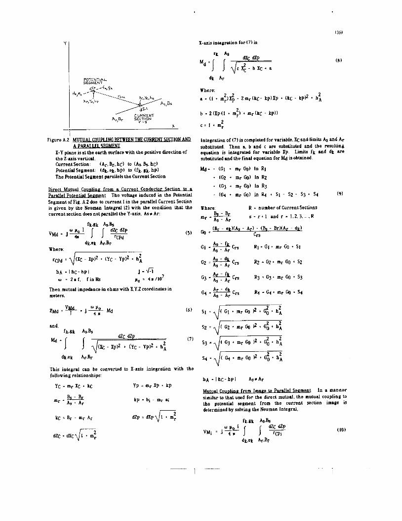
L COUPLING BETWEEN CURRENT SECTION AND Figure A.2 MUTUA I -
X-Y plane is at the earth surface with the positive direction of the Z-axis vertical. Current Section: (Ar. Br. hC) to (As. Bs. hC) Potential Segment (dk, ek, hp) to (fk. gk, hp) The Potential Segment parallels the Current Section
Integration of (7) is completed for variable, Xc and limits AS and Ar substituted. Then a, b and c are substituted and the resulting equation is integrated for variable xp. Limits fk and dk are substituted and the final equation for Md is obtained.
h % ~ = - (GI + m r GO) In RI + (G2 + mr G(I) In R2 + (G3 + mr GO) In R3
- (G4 + mi (30) In R4 + SI - S2 - S3 + S4 (9) Direct Mutual Couolinn from a Current Conductor Section to & m l l e l Potential S- t The voltage induced in the Potential Segment of Fig. A.2 due to current I in the parallel Current Section is given by the Neuman Integral I21 with the condition hat the current section does not parallel the Y-axis, Asc Ar:
Where: R = number of Current Sections
Bs-BT s = r + l a n d r = 1 , 2 , 3 ,,.,,, R
(Br - ek)(As - AI.) - (Bs - Br)(Ar - dk)
mr = As - A r
C O = Crs ( 5 )
hA = I hC- hpl J . 4 3 w = 2.f. f i n % Po = 4. 110'
Then mutual impedance in ohms with X.Y,Z coordinates in meters.
( 6 )
and, fk,gk As&
(7) dZC Md * I I $& - + (GC - YPI2 + hA 2
d t e k
This integral can be converted to X-axis integration with the following relationships:
YC = mp XC + kC
J% - Br
Yp = mr Xp + kp
kp - bi - mr ai mr - AS - Ar
hA = IhC-hp l AscAr
Mutual Couolina from Iman e to Parallel Segment In a manner similar to that used for the direct mutual, the mutual coupling to the potential segment from the current section image is determined by solving the Neuman Integral.
dZp = d x p d l + mr 2 k~ = Br - mr AI.
(10)
- 1 1

I
1270
Whew ( xc - XpI2 + (Yc - Yp)Z + Io 2
hfj = hC + h p
d = b 103 fi, m
j = f i
w = Z r f , f i n k
po = 4 s /IO' p = earthresistivity, n-m
Then mutual impedance in ohms with X.Y.2 coordinates in meters.
(11)
+ (G3 + mr Go) In X3
- (G+ + mr Go) In + Ti - TZ - T3 + T4 (12)
Where: Go, GI. Gz. G3. and G4 am as for the direct mutual c a s .
A.2 MUTUAL COUPLING WHEN THE CURRENT SECTION PARAUELS THE Y-AXIS When a Current Section parallels the Y-axis (As =Al.), formulas
(9). and (12) become indeterminate. The formula for mutual coupling between this Current Section and each Potential Segment is as follows:
(15)
Q = G;! + mrGg + Tz & = G4 + mrGg + T4 T6 I d ( B r - ek)2 + ( A r - dk)* + 1;
= d(& - gkj2 + (Ar - d k P + 1;
Tg = d(b - ek)z + ( A t - dkl2 + 1;
hB = hC + h p As: Ar
on of Section Mutuals Overallmutual impedance between all current sections to all potential sections is determined by the summation of these section mutuals using Eqs. (9 and 12):
Z C P = R M + J X M (13)
R I n
ZCP-Jw* Z Z Z (Md - Mi)
Where:
r=l j-1 k=l
R = number of Current Sections I - number of Potential Section n = number of Segments used to approximate a Potential
Section and k = 1,2,3, ...., n
r - I. 2,3, ...., R i - 1.2.3, ...., I
As: Ar
I o = d h ; + 2 d h g - j ( 2 d 2 + 2 d h B )
h 9 = hC + hP , " d as before
For dk, eh, fk and gk see Eqs. (1.2.3.4)
(14)
on of Section Mutu& Then using Eqs. (15 and 16) mutual from a Current Section that parallels the Y-axis to all Potential Sections:
ZCp = RMY + J XMY (17)
I

1271
I n
ZCP =Ioz Z Z: (MdY - MiY) (18)
Where: i=l k=l
I = number of Potential Section n = number of Segments used to approximate a Potential
i = 1.2.3 ,...., I
Segment and k = 1.2, 3, ...., n AS = Ar
hA cos 8 D2 sin 8
+ tan-1- sin e
Where:
With procedures similar to those used for Current Image the direct angled, mutual coupling from the
Conductor.
(23)
IO COS e 12 sin e
cos e + - 1 - tan-1 - + tan-1 -
sin e sin 8 Figure A 3 1 ETURN ANGLED CONDU(TO&
IO COS e + tan-1-
I3 sin 8 A .3 MUTUAL COUPLING BETWEEN HORI- RETURN -
Mutual coupling between horizontal earth return angled conductors was determined in [ I ] by using the parallel segmented method of approximating the potential conductor. A closed form formula for the angled conductor mutual can be derived by solving the Neuman Integral. In Fig. A.3 conductor P is at angle 9 with conductor C which is conducting current, I. The voltage directly induced in P by current I in C is given by the Neuman Integral. 121.
P C
2 Io cos e + c P sin2 e 11 Io sin e - U - 1 I
Where:
0 + p2 - 2 c p c O s e + 1:
(24)
0 0
hg = hC + hp d = $$ 103 & e = Horizontal Angle between C and P
uruc t A n & d Mutual The direct angled mutual impedance in ohms T- ce Total Mutual Impedance Between Angled Conductors using Eqs. (22) and (24 ,
with C and P in meters.
ZAMd = = J .(, MAd COS e
(25) (20) 7 o = 2.f. f i n k po = 4r / lO
o* e 180. And.
MAd * J J P C
(21) dc d
c2 + p2 - 2 c p COS e + hA2 0 0
The integral solution from Grover I21 is modified by tanh-lA = In 1 + A and changing symbols to C, P. hA and e is,
A.4 MUTUAL COUPLING BFI7REEN VERTICAL CONDUCTORS Mutual coupling between vertical conductors is usually
negligible in comparison with mutual coupling between horizontal earth return conductors. In the Fig. 1 example there is no vertical mutual coupling as the potential conductor is laying on earth. In
1 1

CA NDUCT S FigureA.4 Coordinates:
POT: ai, bi. hi w ai, bi h] CUR: Ar, Br, hr to Ar. Br hs
Fig. A.5 mutual coupling between two 15 m vertical conductors is shown for separations of 5 to 200 m. Both the resistive and reactive components could be neglected for impedance measurements.
Mutual coupling between the vertical conductors of Fig. A.4 as derived with the Neuman Integral results in the following mutual
p in n-m
Overall Vertical Mutual from Eqs. (27) and (29) impedance equations: Direct Vertical Mutual
ZVd = J MVd
MVd = - hi In W1 + h2 In W2
+ h 3 InW3 - h 4 InW4
0 PO
+ v1 - V2 - v3 ' v4
Where:
W1 = h l + V I h i = hs - hj
W2 h2 + V2 h2 = hs - hi
W3 = h 3 + V3 h3 = h r - hj
W4 ii h4 + V4 h4 = h r - hi
EARTH RESISTIVITY. hn
0.0015
0 0010 V4 = 1/ h: + (At. - ail2 + (Br - bi)'
o = 2 x f . f i n k Po = 4 r / ~ ~ 7 Image Vertical Mutual
Ci Uiiil; " 3
'4- * 5- 8 6 -
1 10 100 1000 10000 100000
Figure A.5 MUTUAL COUPLING BETWEEN LINE CONNECTIONS AT Tm P
EARTH RESISTIVITY. R-m
Spacing: f = 6 O k hs = hi = 15m * I = 5 m *3 = 20m '5 = 100m
" 6 = 200m * 2 = 1 o m ' 4 = 50m
Where: = h5 + d - J d + V5 h5 = hs - h j

I
1273
Discussion
Jacques Fortin (Hydro-Quebec): The author's paper extends the under- standing and application of formulas for determining mutual impedance between diversely routed earth return conductors used to measure ground- ing grid impedance. As the grounding impedance measurement could be in error from mutual coupling, current test conductor to potential test conductor, correction of measured impedance may be required. Additional measurement errors can be introduced in the potential conductor by mutual coupling from current flow in overhead neutrals, buried neutrals, overhead ground wires (that are bounded to the substation ground grid and towers), water piping (that connect to the neutral conductors), and buried bare shield conductors, such as contained in urban areas. Are the author's methods applicable to these situations?
On page three of the paper the authors list conditions requiring segmentation of the potential sections. Would the authors indicate the tests used to determine if a potential section is parallel at right angles or angular with a current section? At the end of the page, do the list of angles sections requiring a "n" of 10 or more should be: (czc3, P3P6, PsP6), (c3c4, PIPL,
Is there any advantage to selecting the coordinate system orientation so as to parallel either a current or potential section?
At the meeting the authors presented a comparison between ANSUIEEE Standard 367-1987 and the Segmented Methods of the paper to calculated mutual impedance between a power line and a telephone line given in the standard. This material is of general interest and would be a valuable addition to the paper.
pIp4, p2p3, p4pS, p3pS, PSp6, p3p6), (c4cS, p3p6, PSp6), (c5c63 p3p6, p5p6)?
Manuscript received March 1 , 1990
CLOSURE E J ROGERS AND J F WHITE The authors apprechte the comments. questions, and interest of the discusser
Mr Fortin has raised the very practical problem of errors introduced in the measurement of grounding potential rise by test current flowing in grounding conductors extending externally from the grid Mutual impedance formulas require the exact knowledge of conductor routing relative to the potential conductor and the current distribution in these conductors In urban areas that contain water piping, distribution neutrals and buried shield conductors, all tied to the grid. it is unlikely that these requirements can be entirely satisfied Grounding measurement in these urban cases will require special procedures such as current distribution measurements. potential conductor routing so as to minimize this mutual coupling, step and touch measurements near external circuits that conduct significant portions of the fiiult current to earth, and locating the remote potential electrode 30 m or more from these external earth return circuits In the case of the overhead ground wire bonded to grids and towers. it is possible to make mutual corrections Line sections, in this paper are defined as the straight portions of the line that do not change direction
ANGLLD ANGLED 6NGLFD n m o
Figure C-1 TESTST 0 D E T E R W A POTENTIAL SECT1 ON 0- WITH A CURRENT SECTION
Fig C-1 summarizes condition tests used to determine whether a potential section parallels. is at right angles, o r angular with the current section The authors are in-agreement with the list of angled sections of Fig. 1 requiring a "n" of 10 or more.
Formulas (9, 12, and 14) for calculating mutual impedance between one current section and each potential section and the test program of Fig. C-1 could be simplified and Formulas (15, 16. and 18) eliminated, if the coordinate system were to be oriented to agree with a current section However mutual impedance to potential sections calculated with each subsequent current section will require translation and rotation of the coordinate system axis so as to agree with each new current section. All potential section coordinates would change in each new coordinate system Mr Fortin's suggestion if incorporated in a calculator program. could result in fewer programs steps and possibly less computation time
At the recommendation of Mr. Fortin we are including the comparison between the Segmented Method (057) and the ANSI/IEEE Standard 367-1987 Method 1367) of calculating mutual impedance due to nonuniform exposure 131
In this example mutual impedance is calculated between a power line and telecommunication line shown in Fig. C-2. Figure C-2 is a copy of Fig 35 page 80 in Standard 367. The telephone line is composed of 10 sections extending from A to 0 and back to P. The power line is one straight section Although not stipulated in 367 for this comparison, the power Iine is assumed to start 500 m before "A" and extended 500 m past " 0 With this qualification, the power line will approach the infinite line approximation Recause of additional end-effects, a shorter power line would reduce the 057 calculated mutual coupling Further, the power line height is taken as 15 m and the telephone line height is taken as 7 5 m, which results in a height difference of 7.5 m, as specified by 367
(1) The Carson formula for mutual impedance between infinitely long conductors (2) Uniform earth ( 3 ) Approximating an angled potential section with one o r more parallel segments with their overall parallel separations equal tci the average of the angled separation (4) Neglecting end-effects of finite length conductors. Items ( 1 1 and (4 ) will result in higher mutual impedance component values and item (3) smaller mutual reactive component, XM. values
The segmented method I1 1 is based on ( 1 ) The complex plane approximation for Carson. (2) . Uniform earth. ( 3 ) Accounting for the end-effects between finite length conductors, using both direct and image conductors, as derived with the Neuman Integral. (41 Approximating angled potential sections with 10 or more parallel segments. ( 5 ) . Conductor heights above earth are utilized in the 057 method
Figure C-3 compares the cumulative mutual impedance between the power line and telecommunication line of Fig C-2 calculated with 367 (Refer to page 85 Fig. 38 131 1 and 057 The 057 inductive component XM falls below 367 up to near the line cross under point. The telecommunication line is approximated by 367 with 3 parallel segments in the H-L angled section. This results in a lower estimated XM and the 057 cumulative curve is above 367 after 1575 m. With 057 all angled sections are approximated with 10 parallel segments. RM calculated with 057 is well below the 367 cumulative curve
Figured C-4 is the mutual impedance components, RM and XM, calculated for each telecommunication line section. Fig. C-4 shows the differences between 057 and 367. Table 1 summarizes numerical values of the mutual impedance components calculated with 057 and 367 by line sections. The largest difference in the XM component occurs in the G M section near where the telecommunication line crams under the power line.
The 367 method 131 is based on
1 -- 1

I
0 8 -
0 6 -
0
E
1214
I O 1
Figure C-2 NONUNIFORM ]EXPOSURE BET WEEN A POWER LINE AND A TELF,COMMUN.&ATION LINE Taken from ANSI/IEEE Standard 367-1987 page 80
0 IOW 2ow 3" 100
EXPOSURE LENCTE IN METERS
Figure C-3 CUMULATI VE MUTUAL IMPEDANCE COMPONENTS FOR FIG.C-I f=60If t p-IOOOA-m hc -15m hp=7.5m
\
E-F G M M N N-0 OP A-B C-D
0 lo00 2 0 3 0 - 0 2 i
EXPOSURE LENGTH IN METERS
Figure C-4 MUTUAL IMPEDANCE COMPONENTS FOR EACH LINE SECTION OF F I W f=60I f t p=lOOOA-m h c = 1 5 m hp=7.5m
Figure C-5 shows the overall mutual coupling between the power line and the telecommunication line for earth resistivities 1 to 100.00 A-m as calculated by 057. Earth resistivity variations along the power line could be approximated by two or more resistivity zones.
Table 1 WMPARI SON OF THE MUTUAL IMPEDANCE COMPONENTS CALCULATED BY 367 AND 057 FOR EACH LINE SECTION f = 60 Hz p = IOOOA-m hc = 15 m h p 57.5 m
I
I BC ! c-D I D-E 1 E-F 1 F-G 1 G-M I M-N 1 N-0 I 0-p
El
Y E E
ILTIOE LE"€
m
300 300 300 200 100 225 600 225 675 450
I
367
018
018 012 006 014
014 04 1
.oin
028
- ,027
0090 059 0094 1 068 0064 051 0032 030 0073 1 080
0199
057-0 - 041 ,051 062 ,046 ,029 ,076 240 ,073 ,183
-.097
.ot 367
0 2
10000 1ooooo 0 0
10 IO0 1000
EARTH RESISTIVITY IN OHMS-METERS
Figure C-5 aVERALLMUT UAL IMPEDANCE COMPONENTS FOR FIG . c-1 - h p = 7.5 m f = 6 O k h c = 1 5 m
REFERENCES 131 ANSI/IEEE Standard 367-1987, IEEE Recommended Practice for
Determining the Electric Power Station Ground Potential Rise and Induced Voltage from a Power Fault.
- - I 1