Embed Size (px)
Citation preview
1
Multiuser Wirelessly Powered BackscatterCommunications: Nonlinearity, Waveform Design
and SINR-Energy TradeoffZati Bayani Zawawi, Yang Huang and Bruno Clerckx
Abstract—Wireless power transfer and backscatter commu-nications have emerged as promising solutions for energizingand communicating with power limited devices. Despite someprogress in wirelessly powered backscatter communications,the focus has been concentrated on backscatter and energyharvester. Recently, significant progress has been made on thedesign of transmit multisine waveform, adaptive to the ChannelState Information at the transmitter (CSIT), in point-to-pointbackscatter system. In this paper, we leverage the work andstudy the design of transmit multisine waveform in a multiuserbackscatter system, made of one transmitter, one reader andmultiple tags active simultaneously. We derive an efficient algo-rithm to optimize the transmit waveform so as to identify thetradeoff between the amount of energy harvested at the tagsand the reliability of the communication, measured in termsof Signal-to-Interference-plus-Noise Ratio (SINR) at the reader.Performance with the optimized waveform based on linear andnonlinear energy harvester (EH) models are studied. Numericalresults demonstrate the benefits of accounting for the energyharvester nonlinearity, multiuser diversity, frequency diversityand multisine waveform adaptive to the CSIT to enlarge theSINR-energy region.
Index Terms—Backscatter communications, wireless powertransfer, waveform design, multiuser communication, nonlinearenergy harvesting.
I. INTRODUCTION
In recent years, the study of Wireless Information and PowerTransfer (WIPT) has attracted significant interest among re-searchers [1]. WIPT has appeared in multiple forms such as si-multaneous wireless information and power transfer (SWIPT)where power and information are simultaneously transmit tothe receivers [2], wireless powered communication where thetransmitter transmits power to the receiver, which is thenconverted to DC power and reused for information trans-mission [3] and wireless powered backscatter communicationwhere the transmitter transmits power/unmodulated signal tothe backscatter and the backscatter harvests the energy fromthe received signal or backscatter the received signal back tothe reader [4].
Wirelessly powered backscatter communication is a promis-ing technology for low-power communication systems because
Z. B. Zawawi and B. Clerckx are with the Department of Electrical andElectronic Engineering, Imperial College London, South Kensington Cam-pus London SW72AZ, United Kingdom (email: z.zawawimohd-zawawi13,[email protected]). Y. Huang is with the Department of Informationand Communication Engineering, Nanjing University of Aeronautics andAstronautics, Nanjing 211100, China (email: [email protected]).This work has been partially supported by the EPSRC of the UK under grantEP/P003885/1.
tags can operate with low power as they do not require RFcomponents to generate carrier signal. Although backscattercommunications has originally been limited to simple radiofrequency identification (RFID) applications, it has received arenewed interests in recent years with advances in backscattercommunication theory, including coding [5], beamforming [4],performance analysis of large networks [6], [7].
RF transmitter in backscatter communications typicallytransmit sinusoidal continuous waveform (CW). Significantprogress has recently been made on the waveform designin wireless power transfer (WPT), in order to improve theefficiency and DC output power of the energy harvester. Inparticular, [8] studies the nonlinear behaviour of RF-to-DCconverter and suggests that significant DC power gain canbe obtained by using multisine waveform with zero phasebetween the sinewaves. In [9], a multisine waveform trans-mission has been introduced to extend the reading signal.[10] presented multisine waveform method to improve powersensitivity of the tags and conduct a survey of reading rangeimprovement for several commercial RFID tags. Motivated bythe promising gains, a systematic approach towards waveformdesign for WPT was proposed in [11]. In [11], optimized mul-tisine waveforms, adaptive to the CSIT, have been shown toprovide significant gain by exploiting the rectifier nonlinearityand the frequency selectivity of the channel.
Backscatter communication can leverage this recentprogress in WPT waveform design and depart from the con-ventional CW transmission. Recently, [12] studies the tradeoffbetween harvested energy and backscatter communication inpoint-to-point deployment. It is noted that waveform designfor WPT and backscatter communication is different sincebackscatter communication is subject to a tradeoff betweenharvested energy at the tag and SNR at the reader [12]. In[12], by assuming that the CSIT is available, a systematicdesign of multisine transmit waveform is derived to enlargethe tradeoff region, therefore boosting the overall performanceof backscatter communication.
In this paper, we leverage the work in [12] and studythe design of transmit multisine waveform in a multiuserbackscatter system. To the best of the authors’ knowledge,waveform design in a multiuser wirelessly powered backscat-ter system has not been addressed yet. In this paper, thenonlinear energy harvesting model introduced in [11], [12] is
arX
iv:1
811.
0135
6v1
[cs
.IT
] 4
Nov
201
8
2
used to model the energy harvester 1. This is a general modelof the diode nonlinearity, that is fundamentally motivated bythe physics of the rectifier and is applicable to various rectifiertopologies [13]. The model and the resulting signal designhas been validated through circuit simulations in [11], [13]and experimentations [15]. The model also relies on a Taylorexpansion of the diode characteristics, as commonly donein the RF literature [8]. The contributions of this paper aresummarized in the following paragraphs.
First, by making use of the nonlinear rectenna modelintroduced in [11], we design multisine transmit waveform andcharacterize the SINR-energy region in a K-tags wirelesslypowered backscatter system. In contrast to [11] that onlyconsider transmit waveform for power transfer, this paperneeds to consider transmit waveform for power and backscattercommunication simultaneously. In [12], the tradeoff region fora point-to-point wireless powered communication system hasbeen studied. Here, the optimal phases of multisine waveformweights can be obtained in a closed-form. For given optimalphases, optimizing the magnitudes of the waveform resultsin maximizing non-convex posynomial and can be solvedby using reversed Geometric Programming (GP). Note thatthe algorithm proposed in [12] for K = 1 cannot be usedfor a general K tags system. For a general K-tags system,optimizations over the phases and the magnitudes cannotbe decoupled [17], [18], such that a closed form solutioncannot be obtained and therefore the reversed GP methodcannot be applied. Therefore, a new optimization algorithm isproposed in this paper to jointly optimize the phases and themagnitudes of the multisine waveform for the K-tags system,by making use of the matrix formulation and optimizationtechnique developed in [17], [18]. Additionally, in contrastto the design for a pure Wireless Power Transfer (WPT)system (as in [17], [18]), the design in this paper needs tooptimize the receive combiners at the reader, such that theSINR with respect to a tag can be higher than a threshold.The optimization of the transmit waveform and the receivecombiners are coupled. Therefore, an iterative algorithm isproposed to jointly optimize the transmit waveform and thereceive combiner iteratively.
1In the literature, there are different types of energy harvesting models. Theenergy harvesting model in [11], [12] relates the output DC current/power tothe input signal through the diode I-V characteristics in the nonlinear region.[2] has introduced the linear model of the energy harvester, which ignoresthe diode nonlinearity. In contrast to the nonlinear model in [11], [12], thelinear model may not accurately demonstrate the nonlinearity of the rectifier.Another type of model is the saturation nonlinear model proposed in [16] thatmodels the saturation of the output DC power due to the rectifier operating indiode breakdown region. The difference between the linear model, the diodenonlinear model (used in this paper) and the saturation nonlinear model hasbeen discussed in length in [1], [14]. The diode nonlinear model is moresuited for multiple reasons. First, backscatter communications operate in thelow power regime (typical input power to rectifier is of the order of -20dBm).Second, the diode nonlinear model does reflect the dependence on the inputsignal power and shape and can be used for waveform design (in contrast withthe saturation model that cannot be used for such purpose since it is fitted to agiven pre-defined signal). Third, the diode nonlinearity is beneficial to systemperformance in the low power-regime and therefore should be exploited inbackscatter communications (in contrast with the saturation nonlinearity that isdetrimental to performance and therefore should be avoided by proper rectifierdesign). The readers are referred to [1] and Remark 5 in [14] for extensivediscussions on the various linear and nonlinear models.
Second, the performance of waveform design based on lin-ear and nonlinear rectenna models is studied. It is observed thatwaveform design based on a nonlinear model (4th order trun-cation) has a larger SINR-energy region than those obtainedbased on the linear model. Hence, the rectenna nonlinearity,if properly exploited in the waveform design, is beneficial tothe backscatter communication system performance.
Third, several interesting observations have been foundthrough numerical simulation. Power allocation across mul-tiple sinewaves has been found to enlarge the tradeoff regionby exploiting the frequency selectivity of the channel and thenonlinearity of the rectifier. The gain achieved by waveformsoptimized based on the nonlinear model over those designedbased on linear model increases as the number of sinewavesincreases. It is also observed that the waveform design benefitsfrom multiuser diversity to enlarge the tradeoff between SINRand total amount of energy harvested at the tags. In addition,the performance gap between waveform optimized based onnonlinear and linear models increases as the number of tag in-creases. Nevertheless, the average amount of energy harvestedat each tag decreases as the number of tag increases. This isbecause, the waveform has to be designed to meet the SINRrequirement at all tags, and therefore decrease the averageamount of energy harvested at each tag. Another observation isthat waveform adaptive to the CSIT is beneficial to maximizethe harvested energy for given SINR constraint, such that thetradeoff region is enlarged.
The remainder of this paper is organized as follows. Insection II, we discuss the system model. In section III,we discuss waveform optimization for multiuser backscattercommunications. We present the simulation results in sectionIV and conclude the paper in section V.
In this paper, a bold capital letter and a bold lowercase letter represents a matrix and a vector, respectively. Thenotations (.)∗, (.)?, (.)T , (.)H , Tr(.), |.| and ‖.‖ represent theconjugate, optimal solution, transpose, conjugate transpose,trace, absolute value and 2-norm, respectively. A. indicatesthe DC component of a signal and <. refers to the realnumber. The notation 0 ≤ x ⊥ y ≥ 0 denotes that x ≥ 0,y ≥ 0 and x.y = 0.
II. SYSTEM MODEL
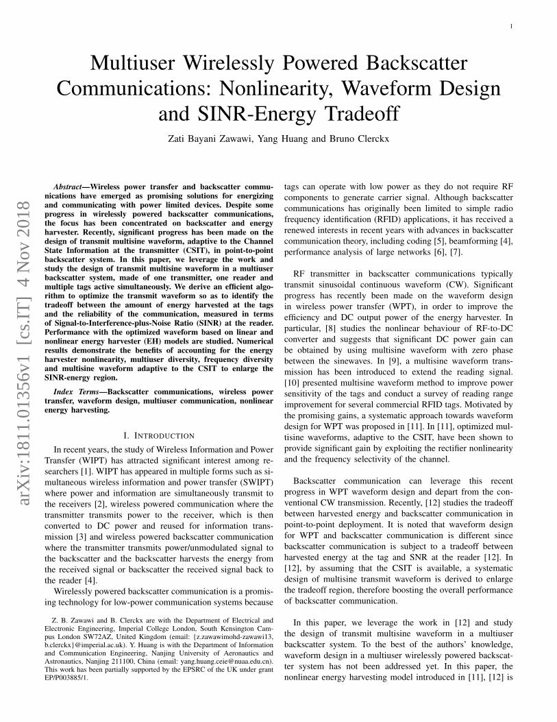
In this section, we provide a system model for multiuserwirelessly powered backscatter communication as shown inFig. 1. An RF transmitter transmits a multisine waveform,with N sinewaves to K tags. Each tag converts the incom-ing RF signal into DC current and transfers information tothe reader (which is co-located with the RF transmitter) bybackscattering modulation. RF transmitter/reader and each taghave a single antenna. We assume that the RF transmitter hasperfect knowledge of the forward channel and the backwardchannel (i.e., channel from tag to reader).
3
Fig. 1. Wirelessly powered backscatter communication with multiple tags.
A. The Transmit Waveform
The transmitter transmits the deterministic multisine wave-form given by
x(t) =
N−1∑n=0
sn cos(ωnt+ φn) = <N−1∑n=0
xneiωnt, (1)
where xn = sneiφn . Here, sn and φn are the amplitude and
the phase of the n-th sinewave at frequency ωn, respectively.The magnitudes and phases in (1) can be collected into vectorss and Φ. The transmit waveform is subject to transmit powerconstraint E|x|2 = 1
2‖s‖2 ≤ P .
After multipath propagation, the received waveform at thej-th tag can be written as
yj(t) =
N−1∑n=0
snAj,n cos(ωnt+ ψj,n) = <N−1∑n=0
hj,nxneiωnt,
(2)where hj,n = Aj,ne
iψj,n =∑L−1l=0 αj,le
i(−ωnτj,l+εj,l) is thefrequency response of the channel between the transmitter andthe j-th tag at frequency component n and ψj,n = ψj,n +φn.τj,l, εj,l and αj,l are the delay, phase and amplitude of thel-th path from the transmitter to the j-th tag, respectively.
B. The Tag Operation
We consider that each tag employs a simple binary modula-tion to transfer information to the reader as in [12]. Binary 0refers to a perfect impedance matching that completely absorbsthe incoming signal and binary 1 refers to a perfect impedancemismatch that completely reflects the incoming signal. Thesignal absorbed during binary 0 operation is conveyed to therectifier for energy harvesting, while the signal reflected duringbinary 1 operation is backscattered to the reader. The readerperforms information detection of sequence bit 0 and 1 fromthe incoming backscattered signal.
C. The Energy Harvester
We will use the same rectenna model as in [11], [12]. Therectenna is made of an antenna and a rectifier. Received poweris transferred from the antenna to the rectifier through the
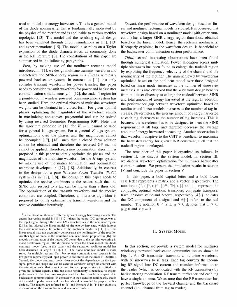
Fig. 2. A single diode rectifier circuit.
matching network. We assume a lossless antenna model withvoltage source vs,j(t) at the j-th tag and antenna impedanceRant = 50Ω is connected to an input impedance of therectifier and matching network Zin,j . With perfect impedancematching 2 where Zin,j = Rant during binary 0 operation, allincoming RF power is completely transferred to the rectifiersuch that Pav,j = E|yj(t)|2 = E|vin,j(t)|2/Rant.
Consider a simple rectifier circuit made of a nonlinear diodefollowed by a low pass filter and a load (i.e. RL) as shownin Fig. 2. The current flowing through the diode at the j-th
tag is given as id,j(t) = is(evd,j(t)
nvt−1 − 1) where vd,j(t) =
vin,j(t)− vout,j(t) is the voltage drop across the diode, is isthe reverse bias saturation current, vt is the thermal voltageand n is the ideality factor. By using Taylor expansion of theexponential function around a fixed voltage drop vd,j = aj ,the diode current can be written as
id,j(t) =
∞∑u=0
k′u,j(vd,j(t)− aj)u (3)
where k′0,j = is(eajnvt − 1), k′u,j = is(
e
ajnvt
u!(nvt)u ) for u =
1, ..,∞. As stated in [11], this energy harvesting model is validonly for small signal where the diode works in the nonlinearregion of diode I-V characteristic. When the signal becomeslarge, the diode series resistance dominates diode behaviourand the diode will be driven into the linear region of I-Vcharacteristic. In this case, the Taylor series based model andthe assumptions made does not hold. For more discussion onthe energy harvesting model, the readers are referred to SectionIII-B in [11].
Assuming a steady state response and ideal rectifier, theoutput voltage delivered to the load is a constant vout,j . When
2The challenge in designing the waveform is to construct an analyticalrectenna model that is accurate and tractable enough to be able to optimizethe transmit waveform. In this paper, perfect impedance matching acrossall frequencies is assumed to balance the complexity and accuracy of themodel. Note that in practice, perfect impedance matching for multisinetransmission cannot be achieved at all the frequencies. Despite this, thewaveform design approach that assumes perfect matching has been validatedby circuit simulations in [11] and [13], where the matching networks usedin circuit simulations are designed by exploiting ADS harmonic balancesimulation. It is also to be noted that in this paper, the inter-frequency spacing(of the order of MHz at most) is very small compared to the carrier frequency(GHz), making the transmission narrowband from an RF design perspective.Even though the impedance mismatch may occur in a multisine transmission,the impact is minimal in a narrowband multisine transmission.
4
aj = Evd,j(t) = −vout,j , (3) can be written as
id,j(t) =
∞∑u=0
k′u,jvin,j(t)u
=
∞∑u=0
k′u,jRu/2antyj(t)
u. (4)
By ignoring the terms higher than 4 3, the DC component in(4) can be written as
id,j(t) =
4∑u=0
k′u,jRu/2antAyj(t)
u. (5)
Following [11], the maximization of (5) is equivalent tomaximizing
zDC,j = k2RantAyj(t)2+ k4R2antAyj(t)
4, (6)
where ku = isu!(nvt)
u ,
Ayj(t)2 =1
2
N∑n=1
s2nA
2j,n (7)
and
Ayj(t)4 =
3
8
[ ∑n1,n2,n3,n4n1+n2
=n3+n4
[snjAj,nm
] cos(ψj,n1+ ψj,n2
− ψj,n3− ψj,n4
)].
(8)For is = 5µA, n = 1.05 and vt = 25.86mV, typical valuesof k2 = 0.0034 and k4 = 0.3829 4. In the sequel, (6) iscalled the nonlinear model of the energy harvester. The linearmodel of the energy harvester is obtained as a special caseby ignoring the 4th order term. By defining the weight 5 forenergy harvested at tag j as cj ≥ 0, we are interested in ageneral metric consisting of a weigthed sum of zDC,j givenby ZDC =
∑Kj=1 cjzDC,j .
D. The Backscattered Signal
The tag completely absorbs and reflects the incoming signalfor binary information 0 and 1, respectively. The receivedsignal at the reader is given as
z(t) = <N∑n=1
K∑j=1
mjhj,nhbj,nxne
i2πfnt+ v(t) (9)
where mj = 0, 1 is the binary information for j-th tag, hbj,n =
Abj,neiψb
j,n is the frequency response of the backward channelbetween the j-th tag and the reader at frequency component nand v(t) is AWGN. After applying a product detector to eachfrequency component and assuming perfect low pass filtering,the baseband received signal at subcarrier n is given by
zn =
K∑j=1
hj,nhbj,nxnmj + vn. (10)
34th order has been described in [8], [11] to be the minimum order todemonstrate the nonlinearity of the rectification.
4These values will be used in any evaluation throughout this paper.5The weights are introduced to provide fairness and priorities among tags.
The weights can be adjusted over time.
vn is the complex white Gaussian noise at frequency compo-nent n with variance σ2. Let z = [z1, .., zN ]
T , the signal zjused for information detection of the j-th tag can be writtenas
zj = gHj z, (11)
where gHj ∈ C1×N is the receive combiner at the reader.It is noted that the SINR of each tag is invariant to the
scaling of gj . Thus, without loss of generality, we define‖gj‖ = 1. The SINR for information detection of the j-thtag can be obtained by
ρj(w,gj) =|gHj Hjw|
2
σ2 + |gHj Hjw|2 , (12)
where w = [x1, .., xN ]T , Hj = diag(hj,1h
bj,1, .., hj,Nh
bj,N )
and Hj = diag(∑Ku 6=j hu,1h
bu,1, ..,
∑Ku 6=j hu,Nh
bu,N ).
E. CSIT Assumption
We assume that the RF transmitter has a perfect knowledgeof CSI of the forward channel hj,n ∀j, n and the backscatterchannel hj,nhbj,n ∀j, n, so that the transmit waveform can beshaped as a function of the channel states to maximize ZDCand ρj . The backscatter channel gain hj,nhbj,n is equal to theproduct of the forward channel gain hj,n and the backwardchannel gain hbj,n. To estimate the backscatter channel, apilot signal can be delivered by the transmitter. This pilotsignal goes through the backscatter channel and is receivedby the reader. Then, by performing least-square estimation[19], the backscatter channel can be estimated. In the presenceof channel reciprocity, hj,n = hbj,n =
√hj,nhbj,n. On the
other hand, for hj,n 6= hbj,n, an additional pilot signal can bedelivered by the tag, such that the backward channel can beestimated at the reader. Thereby, the forward channel gain hj,ncan be easily computed. A long pilot transmission phase canimprove the accuracy of channel estimation, as well as add tothe overhead. Thus, the length of the pilot transmission phasecan be optimized so as to balance the estimation accuracy andthe overhead [19], [20]. It is worth noting that this paper focuson the design of multisine transmit waveform and the effect ofrectenna nonlinearity in a backscatter communication system.The problem of optimizing the length of the pilot transmissionphase can be studied in the future.
We also assume that the reader has a perfect knowledgeof CSI of the backscatter channel hj,nhbj,n ∀j, n, so that thereceive combining can be performed to maximize ρj .
III. WAVEFORM OPTIMIZATON AND SINR-ENERGYTRADEOFF CHARACTERIZATION
In this section, we discuss waveform optimization andcharacterize the tradeoff between achievable SINR and energyharvested for a multiuser backscatter system . The optimizationproblem is formulated as maximizing ZDC given that an SINRconstraint at each tag and an average transmit power constraintare satisfied. The optimization problem is given by
maxw,gj
ZDC : ρj ≥ ρj , ‖w‖2 ≤ 2P, ‖gj‖ = 1,∀j, (13)
5
where ρj is the SINR constraint for the j-th tag and P isthe transmit power constraint. Note that for certain channelrealizations and under the transmit power constraint, theremay not be any w and gj satisfying the SINR constraints.Therefore, we first check the feasibility of problem (13) asdiscussed in the following section.
A. Feasibility Problem
For a given transmit power constraint and channel realiza-tion, problem (13) is feasible when the SINR constraint ρjfor all tags can be satisfied. In the case that the problem hasno solution, (13) is infeasible. Note that the waveform is onlyoptimized when (13) is a feasible problem.
The coupling of the optimization variables w and gj inthe SINR constraints makes problem (13) non-convex. Inthis paper, we propose an algorithm based on alternatingoptimization [21] that optimizes w and gj iteratively. As aresult, we formulate the optimization problem as maximizingan auxiliary variable δ = min
j=1,..,Kρj/ρj, which is used to
check if all SINR constraints are satisfied. Specifically, thefeasibility problem is formulated as
maxw,gj
δ
s. t.|gHj Hjw|
2
σ2‖gj‖2 + |gHj Hjw|2 ≥ δρj , ∀j
‖w‖2 ≤ 2P,
‖gj‖ = 1. ∀j
(14)
Here, (14) is feasible if δ? ≥ 1, which implies that ρj ≥ ρjfor all tags (i.e., the achievable SINR at all tags are larger thantheir corresponding SINR constraint). During the alternatingoptimization, δ is updated by using bisection search methodas in [22] over δmin ≤ δ ≤ δmax. δmin and δmax are chosensuch that δmin < 1 and δmax > 1.
For a given w, the optimal receive combiner that maximizesρj in (14) is given in [26] as
g?j =(HjwwHHH
j + Iσ2)−1
Hjw
‖(HjwwHHHj + Iσ2)
−1Hjw‖
. (15)
For a given gj , as shown in [23], [24], we can adjust thedirection of w such that gHj Hjw is real and non-negativewithout affecting the value of |gHj Hjw| 6. Accordingly, (14)can be recast as
maxw
δ
s. t. (gHj Hjw)2 ≥ δρj(σ2‖gj‖2 + |gHj Hjw|
2), ∀j
‖wj‖2 ≤ 2P, ∀jgHj Hjw = <(gHj Hjw). ∀j
(16)
It can be found that (16) is a SOCP problem and can be solvedby using CVX [25]. Specifically, at iteration l, δ is updated
6Here, we assume that N ≥ K so that we can always get a w such thatgHj Hjw = |gH
j Hjw| for all K tags.
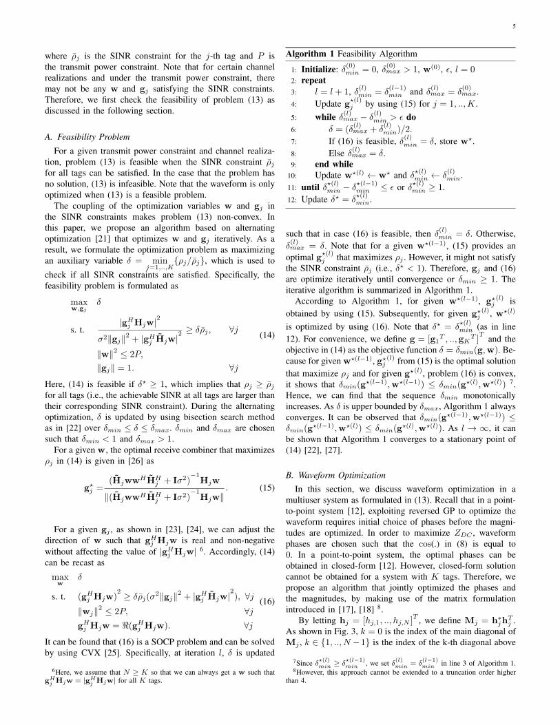
Algorithm 1 Feasibility Algorithm
1: Initialize: δ(0)min = 0, δ(0)
max > 1, w(0), ε, l = 02: repeat3: l = l + 1, δ(l)
min = δ(l−1)min and δ(l)
max = δ(0)max.
4: Update g?(l)j by using (15) for j = 1, ..,K.
5: while δ(l)max − δ(l)
min > ε do6: δ = (δ
(l)max + δ
(l)min)/2.
7: If (16) is feasible, δ(l)min = δ, store w?.
8: Else δ(l)max = δ.
9: end while10: Update w?(l) ← w? and δ?(l)min ← δ
(l)min.
11: until δ?(l)min − δ?(l−1)min ≤ ε or δ?(l)min ≥ 1.
12: Update δ? = δ?(l)min.
such that in case (16) is feasible, then δ(l)min = δ. Otherwise,
δ(l)max = δ. Note that for a given w?(l−1), (15) provides an
optimal g?(l)j that maximizes ρj . However, it might not satisfy
the SINR constraint ρj (i.e., δ? < 1). Therefore, gj and (16)are optimize iteratively until convergence or δmin ≥ 1. Theiterative algorithm is summarized in Algorithm 1.
According to Algorithm 1, for given w?(l−1), g?j(l) is
obtained by using (15). Subsequently, for given g?j(l), w?(l)
is optimized by using (16). Note that δ? = δ?(l)min (as in line
12). For convenience, we define g = [g1T , ..,gK
T ]T and the
objective in (14) as the objective function δ = δmin(g,w). Be-cause for given w?(l−1), g?j
(l) from (15) is the optimal solutionthat maximize ρj and for given g?(l), problem (16) is convex,it shows that δmin(g?(l−1),w?(l−1)) ≤ δmin(g?(l),w?(l)) 7.Hence, we can find that the sequence δmin monotonicallyincreases. As δ is upper bounded by δmax, Algorithm 1 alwaysconverges. It can be observed that δmin(g?(l−1),w?(l−1)) ≤δmin(g?(l−1),w?(l)) ≤ δmin(g?(l),w?(l)). As l → ∞, it canbe shown that Algorithm 1 converges to a stationary point of(14) [22], [27].
B. Waveform Optimization
In this section, we discuss waveform optimization in amultiuser system as formulated in (13). Recall that in a point-to-point system [12], exploiting reversed GP to optimize thewaveform requires initial choice of phases before the magni-tudes are optimized. In order to maximize ZDC , waveformphases are chosen such that the cos(.) in (8) is equal to0. In a point-to-point system, the optimal phases can beobtained in closed-form [12]. However, closed-form solutioncannot be obtained for a system with K tags. Therefore, wepropose an algorithm that jointly optimized the phases andthe magnitudes, by making use of the matrix formulationintroduced in [17], [18] 8.
By letting hj = [hj,1, .., hj,N ]T , we define Mj = h∗jh
Tj .
As shown in Fig. 3, k = 0 is the index of the main diagonal ofMj , k ∈ 1, .., N −1 is the index of the k-th diagonal above
7Since δ?(l)min ≥ δ?(l−1)min , we set δ(l)min = δ
(l−1)min in line 3 of Algorithm 1.
8However, this approach cannot be extended to a truncation order higherthan 4.
6
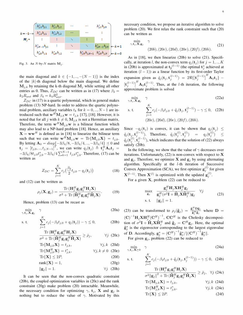
Fig. 3. An N -by-N matrix Mj .
the main diagonal and k ∈ −1, ..,−(N − 1) is the indexof the |k|-th diagonal below the main diagonal. We defineMj,k by retaining the k-th diagonal Mj while setting all otherentries as 0. Thus, ZDC can be written as in (17) where β2 =k2Rant and β4 = k4R
2ant.
ZDC in (17) is a quartic polynomial, which in general makesproblem (13) NP-hard. In order to address the quartic polyno-mial problem, auxiliary variables tk for k = 0, .., N−1 are in-troduced such that wHMj,kw = tj,k [17], [18]. However, it isnoted that for all j with k 6= 0, Mj,k is not a Hermitian matrix.Therefore, the term wHMj,kw is a bilinear function whichmay also lead to a NP-hard problem [18]. Hence, an auxiliaryX = wwH is defined as in [18] to linearize the bilinear termsuch that we can write wHMj,kw = TrMj,kX = tj,k.By letting A0 = diag−3β4/8,−3β4/4, ..,−3β4/4 0 andtj = [tj,0, .., tj,N−1]
T , we can write qj(tj) , tHj A0tj =
−3β4/8tj,0t∗j,0−3β4/4
∑N−1k=1 tj,kt
∗j,k. Therefore, (17) can be
written as
ZDC =
K∑j=1
cj(β2
2tj,0 − qj(tj)
)(18)
and (12) can be written as
ρj(X,gj) =Tr (HH
j gjgHj HjX)
σ2 + Tr (HHj gjgHj HjX)
. (19)
Hence, problem (13) can be recast as
minγ,tj ,X,gj
γ (20a)
s. t.K∑j=1
cj(−β2tj,0 + qj(tj))− γ ≤ 0, (20b)
Tr (HHj gjg
Hj HjX)
σ2 + Tr (HHj gjgHj HjX)
≥ ρj , ∀j (20c)
TrMj,kX = tj,k, ∀j, k (20d)
TrMHj,kX = t∗j,k, ∀j, k 6= 0 (20e)
TrX ≤ 2P, (20f)rankX = 1, (20g)‖gj‖ = 1. ∀j (20h)
It can be seen that the non-convex quadratic constraint(20b), the coupled optimization variables in (20c) and the rankconstraint (20g) make problem (20) intractable. Meanwhile,the necessary condition for optimizing γ, tj , X and gj isnothing but to reduce the value of γ. Motivated by this
necessary condition, we propose an iterative algorithm to solveproblem (20). We first relax the rank constraint such that (20)can be written as
minγ,tj ,X,gj
γ
(20b), (20c), (20d), (20e), (20f), (20h).(21)
As in [18], we then linearize (20b) to solve (21). Specifi-cally, at iteration l, the non-convex term qj(tj) for j = 1, ..,Kin (20b) is approximated at tj
(l−1) (the optimal t?j achieved atiteration (l − 1)) as a linear function by its first-order Taylor
expansion given as qj(tj , t(l−1)j ) = 2<[t(l−1)
j ]H
A0tj −[t
(l−1)j ]
HA0t
(l−1)j . Thus, at the l-th iteration, the following
approximate problem is solved
minγ,tj ,X,gj
γ (22a)
s. t.K∑j=1
cj(−β2tj,0 + qj(tj , t(l−1)j )− γ ≤ 0, (22b)
(20c), (20d), (20e), (20f), (20h).
Since −qj(tj) is convex, it can be shown that qj(tj) ≤qj(tj , t
(l−1)j ). Therefore, qj(t
(l)j , t
(l)j ) = qj(t
(l)j ) ≤
qj(t(l)j , t
(l−1)j ), which indicates that the solution of (22) always
satisfy (20b).In the following, we show that the value of γ decreases over
iterations. Unfortunately, (22) is non-convex with respect to Xand gj . Therefore, we optimize X and gj by using alternatingalgorithm. Specifically at the l-th iteration of SuccessiveConvex Approximation (SCA), we first optimize g
(l)j for given
X(l−1). Then X(l) is optimized with the updated g(l)j .
For a given X, problem (22) can be reduced to
maxgj
gHj HjXHHj gj
gHj (σ2I + HjXHHj )gj
∀j
s. t. ‖gj‖ = 1.
(23)
(23) can be transformed to ρj(gj) =gHj Dgj
gHj gj
where D =
(C)−1
HjXHHj (CH)
−1, CCH is the Cholesky decomposi-tion of σ2I + HjXHH
j and gj = CHgj . Here, the optimalg?j is the eigenvector corresponding to the largest eigenvalueof D. Accordingly, g?j = (CH)
−1g?j/‖(CH)
−1g?j‖.
For given gj , problem (22) can be reduced to
minγ,tj ,X0
γ (24a)
s. t.K∑j=1
cj(−β2tj,0 + qj(tj , t(l−1)j ))− γ ≤ 0, (24b)
Tr (HHj gjg
Hj HjX)
σ2‖gj‖2 + Tr (HHj gjgHj HjX)
≥ ρj , ∀j (24c)
TrMj,kX = tj,k, ∀j, k (24d)
TrMHj,kX = t∗j,k, ∀j, k (24e)
TrX ≤ 2P. (24f)
7
ZDC =
K∑j=1
cj
(1
2β2∑n
w∗nh
∗j,nhj,nwn +
3
8β4
∑n1,n2,n3,n4
n1−n3=−(n2−n4)
w∗n3h∗j,n3
hj,n1wn1w∗n4h∗j,n4
hj,n2wn2
)
=
K∑j=1
cj
(1
2β2w
HMj,0w +3
8β4w
HMj,0w(wHMj,0w)H
+3
4β4
N−1∑k=1
wHMj,kw(wHMj,kw)H). (17)
Algorithm 2 Iterative Algorithm
1: Initialize: l(0) ← 0, X(0), ε, γ(0) and update t(0)j
K
j=1by (24d).
2: repeat3: l = l + 14: Find g?j in (23); g
(l)j ← g?j .
5: Solve SDP problem in (24); X(l) ← X?, γ(l) ← γ?.6: Update t(l)j,k ∀ j, k in (24d) and (24e).7: until |γ(l) − γ(l−1)|/|γ(l)| ≤ ε .8: Find rank-one solution of X?.
(24) is a SDP problem and can be solved by CVX 9.
The iterative algorithm to solve (22) is summarized inAlgorithm 2 (from line 2 to line 7)10. Because g?j is theglobal optimal solution of problem (23) and problem (24) isconvex, it shows that γ(l−1) ≥ γ(l). Note that the stoppingcriterion of Algorithm 2 is related to the convergence of γ(i.e., objective function of problem (22)). As the value of γ ismonotonically decreasing and bounded, the iterative algorithmis guaranteed to converge. In the Appendix, we show thatunder the condition that the eigenvector of D can be uniquelyobtained, the minimizers in Algorithm 2 converges to a KKTpoint of problem (22).
Solving the SDP problem (24) by using the interior pointmethod usually yields a high-rank X? solution [29]. In thefollowing, in order to obtain the rank-constrained solution thatsatisfy (20g), we derive a rank-one solution from the high rankX? (line 8 of Algorithm 2).
1) Obtaining a Rank-One X: We first show that if K ≤ 2(i.e., j = 1, 2), (21) can offer a rank-one optimal solution ofX? although the solution in (24) has a high rank of X?. From
9Problem (24) has a solution if for given gj , (24) is a feasible problem.The solution from Algorithm 1 w? can be used as the initial point in theiterative algorithm such that X(0) = w?w?H . Therefore, a feasible solutionof (24) (and also (22)) can always be obtained.
10The transmitter may be subject to the transmit power spectrum densityconstraint. Power spectrum density constraint could refer to the limit oftransmit power at each frequency sub-band [28]. Power spectrum densityconstraint can be formulated as 1/2|sn|2 ≤ Ps ∀n in problem (13), wherePs is the transmit power spectrum density constraint. The constraint can bereformulated as diag(X) ≤ 2Ps in problem (22) and (24). Problem (24) withthe new additional constraint is an SDP problem and can be solved by usingCVX. The iterative algorithm to solve (22) with additional power spectrumdensity constraint is summarized in Algorithm 2.
[18], (21) can be converted into an equivalent form as
minX0,gj
TrAX
s. t.Tr (HH
j gjgHj HjX)
σ2 + Tr (HHj gjgHj HjX)
≥ ρj , ∀j
TrX ≤ 2P,
‖gj‖ = 1. ∀j
(25)
where A = C + CH is a Hermitian and C =∑Kj=1 cj(−
β2+3/2β4t(l−1)j,0
4 Mj,0−3/4β4
∑N−1k=1 [t
(l−1)j,k ]
∗Mj,k).
Given an optimized g?j and by defining Bj = (HHg?jg?jHH−
HHg?jg?jHH), (25) can be recast as
minX0
TrAX
s. t. Tr (BjX)− σ2ρj ≥ 0, ∀jTrX ≤ 2P,
(26)
where Bj is Hermitian. According to [30], (26) is shown tobe a separable SDP. By applying [30, Proposition 3.5], wecan show that (26) can yield a rank one optimal solutionwhen K ≤ 2. Accordingly, a rank one X∗r1 = w?w?H canbe obtained by using Rank Reduction (RR) [30]. Hence, wepropose an algorithm that first iteratively optimizes gj in (23)and X in (24). RR precedure is then performed to the highrank solution of X? to find w?.
When K ≥ 3, (26) may not have a rank-one optimalsolution of X?. In this scenario, we solve (21) by iterativelyoptimizing gj in (23) and X in (24) until convergence. Then,rank randomization method is performed to obtain T rank-onesolution from higher rank of X?. By taking the eigenvaluedecomposition (EVD) X? = UΣ1/2UH , we generate Trandom vectors wt = UΣ1/2vt for t = 1, .., T wherevt is a random vector with each complementary entry isfrom a circular uniform distribution such that E[vtv
Ht ] = I.
For each wt, we find their corresponding gt,j from (15).Consequently, the best feasible rank-one solution satisfyingconstraint (20c) and (20f) is obtained as follows. AmongT wt and their corresponding gt,j , we find w
′
t and g′
t,j
that can satisfy constraint (20c) and (20f). Accordingly, thebest feasible solution is w? = argmaxw
′tZDC(w
′
t) whereX?r1 = w?w?H and g?j is given as g
′
t,j that associate withw?.
2) A Simplified Algorithm: A simplified iterative algorithmwith a lower computational complexity than Algorithm 2 isproposed. Given an initial value of X with its correspondingg∗j from (23), by fixing g∗j at each iteration, (24) is optimizediteratively until convergence. Then, a rank-one X is obtainedas discussed in section III-B-1. The iterative algorithm isshown in Algorithm 3. For given g?j in line 2, the iterative
8
Algorithm 3 A Simplified Algorithm
1: Initialize: l(0) ← 0, X(0), ε, γ(0) and update t(0)j
K
j=1by (24d).
2: Find g?j in (23) for given X(0).3: repeat4: l = l + 15: Solve SDP problem in (24); X(l) ← X?, γ(l) ← γ?.6: Update t(l)j,k ∀ j, k by (24d) and (24e).7: until |γ(l) − γ(l−1)|/|γ(l)| ≤ ε .8: Find rank-one solution of X?.
algorithm converges to a stationary point of (24) [18]. Al-though this algorithm provides a lower complexity comparedto Algorithm 2, the performance of Algorithm 2 is expectedto be better. This is because alternating optimization thatoptimizes gj (in line 4 of Algorithm 2) and X iteratively inAlgorithm 2 can reduce the value of γ over the iterations.
IV. SIMULATION RESULTS
We consider a system with a centre frequency of 5.18 GHz,10 MHz bandwidth, 36 dBm EIRP, 2 dBi receive and transmitantenna gain at the tag and 2 dBi receive antenna gain at thereader. The path loss for forward and backward link are 58 dBand the NLOS channel power delay profile is obtained frommodel B [31]. The channel taps each with an average powerβl, are independent, circularly symmetric complex randomGaussian distributed and normalized such that
∑l βl = 1.
This leads to an average receive power of -20 dBm at the tag.The SNR at the reader is defined as P/σ2. In the simulation,it is assumed that each tag has the same SINR constraint ρ.For simplicity the weight for energy harvested cj = 1 for alltags.
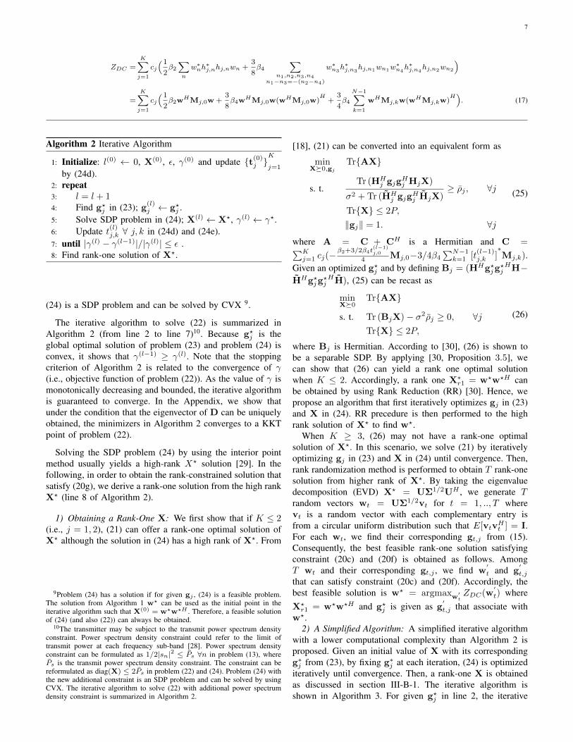
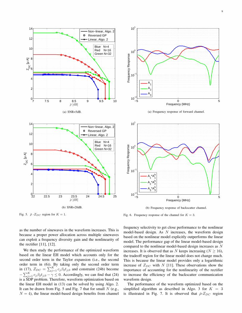
Simulation for K = 1 and K = 3 are run over a channelrealization for two different SNRs (5 and 20 dB). The channelfrequency responses are illustrated in Fig. 4 for K = 1 andFig. 6 for K = 3. The ρ-ZDC region for K = 1 and K = 3are shown in Fig. 5 and Fig. 7, respectively. The ZDC onthe y-axis is given in (17). The SINR (SNR for a point-to-point system) on the x-axis is the SINR constraint ρ. Theblue, red and green colours in the figures refer to N = 4, 16and 32, respectively. The solid lines in the figures indicatethe result for waveform optimization based on nonlinearEH model and obtained by using Algo. 2. In point-to-pointsystem where K = 1, there is no interference signal. Themaximum achievable SNR in Fig. 5 are obtained by allocatingfull transmit power to a single subcarrier corresponding toargmaxn |h1,nh
b1,n|. On the other hand, the maximum ZDC
can be obtained from [11], [18]. For K = 3, the extreme pointon the x-axis and y-axis in Fig. 7 are obtained from Algo. 1and [18], respectively.
Note that for a point-to-point system, the phase of thetransmit waveform can be obtained in a closed-form as in [12]11. Accordingly, power allocation across frequency componentcan be optimized by using Reversed GP [12]. It is observed
11However, closed-form solution cannot be obtained when K > 1.
−5 0 510
−2
10−1
100
101
Fre
quen
cy R
espo
nse
Frequency (MHz)
A1
A1b
A1*A
1b
Fig. 4. Frequency response of the channel for K = 1.
TABLE IELAPSED RUNNING TIME:ALGORITHM 2 VS. REVERSED GP
that the achievable ρ-ZDC regions obtained by using ReversedGP and Algo. 2 are comparable as shown in Fig. 5 12. Table Icompares the average computational complexity for waveformoptimization based on Algo. 2 and Reversed GP. ZDC and theelapsed time are averaged over several channel realizationswith N = 4, 8. To draw the comparison between the ReversedGP approach and Algo. 2, we employ the same initial pointand ε = 10−7 for both algorithms and the SNR constraint atthe tag ρ = 10dB. The simulation is conducted by MATLABR2013b on a computer with an Intel Core i7 processor at3.3GHz, RAM of 16GB and Windows 10 Pro. The simulationresults show that the average elapsed time for Algo. 2 issignificantly less than Reversed GP, while the ZDC valuefrom both algorithms is comparable. In terms of asymptoticcomputational complexity, the Reversed GP algorithm suffersfrom exponential complexity [32] to compute an optimalsolution while solving SDP by using interior point method maytake polynomial complexity [33] per iteration in Algorithm 2.
From Fig. 5 and Fig. 7, by looking at the ρ-ZDC regionfor the nonlinear EH model obtained from Algo. 2, it is ob-served that the performance of wirelessly powered backscattercommunication is subject to a tradeoff between ZDC and ρ.That is, maximizing the ZDC would result in a decrease inρ. The second observation is that by looking at two differentSNRs (5 and 20 dB), the ρ-ZDC tradeoff slope (i.e., rate ofchange) decreases as the value of SNR increases, for each N .Another observation is that, the tradeoff region can be enlarged
12Due to the non-convexity of the problem, the solutions from Reversed GPand Algorithm 2 cannot guarantee to converge to the global optimal solution.However, both approaches converge to a KKT point.
9
7 7.5 8 8.5 9 9.5 100
2
4
6
8
10
12
14Z
DC
[µ A
]
ρ [dB]
Non−linear, Algo. 2Reversed GPLinear, Algo. 2
Blue N=4Red N=16Green N=32
(a) SNR=5dB.
22 22.5 23 23.5 24 24.5 250
2
4
6
8
10
12
14
ρ [dB]
ZD
C [µ
A]
Non−linear, Algo. 2Reversed GPLinear, Algo. 2
Blue N=4Red N=16Green N=32
(b) SNR=20dB.
Fig. 5. ρ -ZDC region for K = 1.
as the number of sinewaves in the waveform increases. This isbecause a proper power allocation across multiple sinewavescan exploit a frequency diversity gain and the nonlinearity ofthe rectifier [11], [12].
We then study the performance of the optimized waveformbased on the linear EH model which accounts only for thesecond order term in the Taylor expansion (i.e., the secondorder term in (6)). By taking only the second order termin (17), ZDC =
∑Kj=1 cjβ2tj,0 and constraint (24b) become
−∑Kj=1 cjβ2tj,0 − γ ≤ 0. Accordingly, we can find that (24)
is a SDP problem. Therefore, waveform optimization based onthe linear EH model in (13) can be solved by using Algo. 2.It can be drawn from Fig. 5 and Fig. 7 that for small N (e.g.,N = 4), the linear model-based design benefits from channel
−5 0 510
−2
10−1
100
101
Fre
quen
cy R
espo
nse
Frequency (MHz)
A1
A2
A3
(a) Frequency response of forward channel.
−5 0 510
−2
10−1
100
101
Fre
quen
cy R
espo
nse
Frequency (MHz)
A1*A
1b
A2*A
2b
A3*A
3b
(b) Frequency response of backscatter channel.
Fig. 6. Frequency response of the channel for K = 3.
frequency selectivity to get close performance to the nonlinearmodel-based design. As N increases, the waveform designbased on the nonlinear model explicitly outperforms the linearmodel. The performance gap of the linear model-based designcompared to the nonlinear model-based design increases as Nincreases. It is observed that as N keeps increasing (N ≥ 16),the tradeoff region for the linear model does not change much.This is because the linear model provides only a logarithmicincrease of ZDC with N [11]. These observations show theimportance of accounting for the nonlinearity of the rectifierto increase the efficiency of the backscatter communicationwaveform design.
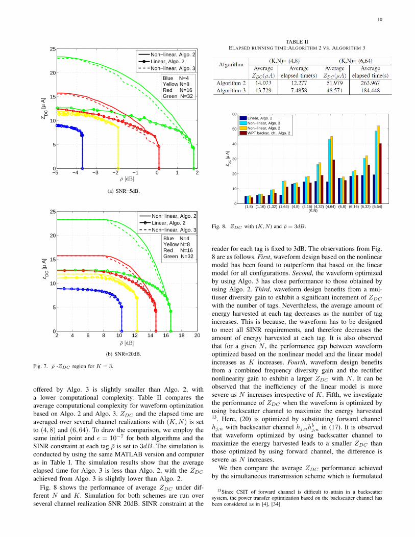
The performance of the waveform optimized based on thesimplified algorithm as described in Algo. 3 for K = 3is illustrated in Fig. 7. It is observed that ρ-ZDC region
10
−5 −4 −3 −2 −1 0 1 20
5
10
15
20
25
ρ [dB]
ZD
C [µ
A]
Non−linear, Algo. 2Linear, Algo. 2Non−linear, Algo. 3
Blue N=4Yellow N=8Red N=16Green N=32
(a) SNR=5dB.
2 4 6 8 10 12 14 16 18 200
5
10
15
20
25
ρ [dB]
z DC
[µ A
]
Non−linear, Algo. 2Linear, Algo. 2Non−linear, Algo. 3
Blue N=4Yellow N=8Red N=16Green N=32
(b) SNR=20dB.
Fig. 7. ρ -ZDC region for K = 3.
offered by Algo. 3 is slightly smaller than Algo. 2, witha lower computational complexity. Table II compares theaverage computational complexity for waveform optimizationbased on Algo. 2 and Algo. 3. ZDC and the elapsed time areaveraged over several channel realizations with (K,N) is setto (4, 8) and (6, 64). To draw the comparison, we employ thesame initial point and ε = 10−7 for both algorithms and theSINR constraint at each tag ρ is set to 3dB. The simulation isconducted by using the same MATLAB version and computeras in Table I. The simulation results show that the averageelapsed time for Algo. 3 is less than Algo. 2, with the ZDCachieved from Algo. 3 is slightly lower than Algo. 2.
Fig. 8 shows the performance of average ZDC under dif-ferent N and K. Simulation for both schemes are run overseveral channel realization SNR 20dB. SINR constraint at the
TABLE IIELAPSED RUNNING TIME:ALGORITHM 2 VS. ALGORITHM 3
(1,8) (1,16) (1,32) (1,64) (4,8) (4,16) (4,32) (4,64) (6,8) (6,16) (6,32) (6,64)0
10
20
30
40
50
60
(K,N)
ZD
C [µ
A]
Linear, Algo. 2Non−linear, Algo. 3Non−linear, Algo. 2WPT backsc. ch., Algo. 2
Fig. 8. ZDC with (K,N ) and ρ = 3dB.
reader for each tag is fixed to 3dB. The observations from Fig.8 are as follows. First, waveform design based on the nonlinearmodel has been found to outperform that based on the linearmodel for all configurations. Second, the waveform optimizedby using Algo. 3 has close performance to those obtained byusing Algo. 2. Third, waveform design benefits from a mul-tiuser diversity gain to exhibit a significant increment of ZDCwith the number of tags. Nevertheless, the average amount ofenergy harvested at each tag decreases as the number of tagincreases. This is because, the waveform has to be designedto meet all SINR requirements, and therefore decreases theamount of energy harvested at each tag. It is also observedthat for a given N , the performance gap between waveformoptimized based on the nonlinear model and the linear modelincreases as K increases. Fourth, waveform design benefitsfrom a combined frequency diversity gain and the rectifiernonlinearity gain to exhibit a larger ZDC with N . It can beobserved that the inefficiency of the linear model is moresevere as N increases irrespective of K. Fifth, we investigatethe performance of ZDC when the waveform is optimized byusing backscatter channel to maximize the energy harvested13. Here, (20) is optimized by substituting forward channelhj,n with backscatter channel hj,nhbj,n in (17). It is observedthat waveform optimized by using backscatter channel tomaximize the energy harvested leads to a smaller ZDC thanthose optimized by using forward channel, the difference issevere as N increases.
We then compare the average ZDC performance achievedby the simultaneous transmission scheme which is formulated
13Since CSIT of forward channel is difficult to attain in a backscattersystem, the power transfer optimization based on the backscatter channel hasbeen considered as in [4], [34].
11
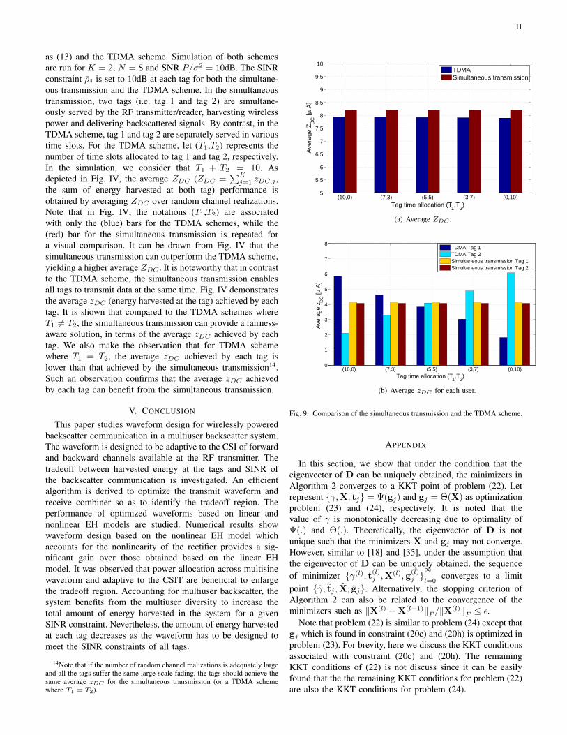
as (13) and the TDMA scheme. Simulation of both schemesare run for K = 2, N = 8 and SNR P/σ2 = 10dB. The SINRconstraint ρj is set to 10dB at each tag for both the simultane-ous transmission and the TDMA scheme. In the simultaneoustransmission, two tags (i.e. tag 1 and tag 2) are simultane-ously served by the RF transmitter/reader, harvesting wirelesspower and delivering backscattered signals. By contrast, in theTDMA scheme, tag 1 and tag 2 are separately served in varioustime slots. For the TDMA scheme, let (T1,T2) represents thenumber of time slots allocated to tag 1 and tag 2, respectively.In the simulation, we consider that T1 + T2 = 10. Asdepicted in Fig. IV, the average ZDC (ZDC =
∑Kj=1 zDC,j ,
the sum of energy harvested at both tag) performance isobtained by averaging ZDC over random channel realizations.Note that in Fig. IV, the notations (T1,T2) are associatedwith only the (blue) bars for the TDMA schemes, while the(red) bar for the simultaneous transmission is repeated fora visual comparison. It can be drawn from Fig. IV that thesimultaneous transmission can outperform the TDMA scheme,yielding a higher average ZDC . It is noteworthy that in contrastto the TDMA scheme, the simultaneous transmission enablesall tags to transmit data at the same time. Fig. IV demonstratesthe average zDC (energy harvested at the tag) achieved by eachtag. It is shown that compared to the TDMA schemes whereT1 6= T2, the simultaneous transmission can provide a fairness-aware solution, in terms of the average zDC achieved by eachtag. We also make the observation that for TDMA schemewhere T1 = T2, the average zDC achieved by each tag islower than that achieved by the simultaneous transmission14.Such an observation confirms that the average zDC achievedby each tag can benefit from the simultaneous transmission.
V. CONCLUSION
This paper studies waveform design for wirelessly poweredbackscatter communication in a multiuser backscatter system.The waveform is designed to be adaptive to the CSI of forwardand backward channels available at the RF transmitter. Thetradeoff between harvested energy at the tags and SINR ofthe backscatter communication is investigated. An efficientalgorithm is derived to optimize the transmit waveform andreceive combiner so as to identify the tradeoff region. Theperformance of optimized waveforms based on linear andnonlinear EH models are studied. Numerical results showwaveform design based on the nonlinear EH model whichaccounts for the nonlinearity of the rectifier provides a sig-nificant gain over those obtained based on the linear EHmodel. It was observed that power allocation across multisinewaveform and adaptive to the CSIT are beneficial to enlargethe tradeoff region. Accounting for multiuser backscatter, thesystem benefits from the multiuser diversity to increase thetotal amount of energy harvested in the system for a givenSINR constraint. Nevertheless, the amount of energy harvestedat each tag decreases as the waveform has to be designed tomeet the SINR constraints of all tags.
14Note that if the number of random channel realizations is adequately largeand all the tags suffer the same large-scale fading, the tags should achieve thesame average zDC for the simultaneous transmission (or a TDMA schemewhere T1 = T2).
(10,0) (7,3) (5,5) (3,7) (0,10)5
5.5
6
6.5
7
7.5
8
8.5
9
9.5
10
Tag time allocation (T1,T
2)
Ave
rage
ZD
C [µ
A]
TDMASimultaneous transmission
(a) Average ZDC .
(10,0) (7,3) (5,5) (3,7) (0,10)0
1
2
3
4
5
6
7
8
Tag time allocation (T1,T
2)
Ave
rage
zD
C [µ
A]
TDMA Tag 1TDMA Tag 2Simultaneous transmission Tag 1Simultaneous transmission Tag 2
(b) Average zDC for each user.
Fig. 9. Comparison of the simultaneous transmission and the TDMA scheme.
APPENDIX
In this section, we show that under the condition that theeigenvector of D can be uniquely obtained, the minimizers inAlgorithm 2 converges to a KKT point of problem (22). Letrepresent γ,X, tj = Ψ(gj) and gj = Θ(X) as optimizationproblem (23) and (24), respectively. It is noted that thevalue of γ is monotonically decreasing due to optimality ofΨ(.) and Θ(.). Theoretically, the eigenvector of D is notunique such that the minimizers X and gj may not converge.However, similar to [18] and [35], under the assumption thatthe eigenvector of D can be uniquely obtained, the sequenceof minimizer γ(l), t
(l)j ,X
(l),g(l)j ∞
l=0converges to a limit
point γ, tj , X, gj. Alternatively, the stopping criterion ofAlgorithm 2 can also be related to the convergence of theminimizers such as ‖X(l) −X(l−1)‖F /‖X(l)‖F ≤ ε.
Note that problem (22) is similar to problem (24) except thatgj which is found in constraint (20c) and (20h) is optimized inproblem (23). For brevity, here we discuss the KKT conditionsassociated with constraint (20c) and (20h). The remainingKKT conditions of (22) is not discuss since it can be easilyfound that the the remaining KKT conditions for problem (22)are also the KKT conditions for problem (24).

12
Let γ, tj ,X,gj and Lagrangian multipliersµ, νj , ξj,k, ηj,k, $, κj associated with constraints(22b), (20c), (20d), (20e), (20f), (20h) satisfy theKKT conditions of problem (22). Let f
′
j,k(X, tj,k) =
TrMj,kX − tj,k, f′′
j,k(X, tj,k) = TrMHj,kX − t∗j,k and
f′′′
(X) = TrX − 2P . From the Lagrangian of problem(22), the KKT conditions associated with constraint (20c) and(20h) are as follows
K∑j=1
νj∇Xρj(X,gj) +
K∑j=1
N−1∑k=0
ξj,k∇Xf′
j,k(X, tj,k)+
K∑j=1
N−1∑k=1
ηj,k∇Xf′′
j,k(X, tj,k) +$∇Xf′′′
(X) = 0, (27a)
νj∇gjρj(X,gj) = 0, ∀j (27b)
0 ≤ νj ⊥ ρj(X,gj)− ρj ≥ 0 ∀j (27c)
‖gj‖ = 1 ∀j (27d)
Based on problem (24), γ, tj , X with Lagrangian mul-tipliers (µ, νj , ξj,k, ηj,m, $) associated with constraints(24b), (24c), (24d), (24e), (24f) must satisfy the KKT con-ditions of problem (24). The KKT conditions of problem (24)associated with constraint (20c) and (20h) are
K∑j=1
νj∇Xρj(X, gj) +
K∑j=1
N−1∑k=0
ξj,k∇Xf′
j,k(X, tj,k)+
K∑j=1
N−1∑k=1
ηj,k∇Xf′′
j,k(X, tj,k) + $∇Xf′′′
j,k(X) = 0, (28a)
0 ≤ νj ⊥ ρj(X, gj)− ρj ≥ 0. ∀j (28b)
Based on problem (23), gj must satisfy the KKT conditionsof problem (23). The KKT conditions of problem (23) are
∇gjρj(X, gj) = 0, ∀j (29a)
‖gj‖ = 1. ∀j (29b)
Multipying (29a) by νj , the KKT conditions in (29) are givenas
νj∇gjρj(X, gj) = 0, ∀j (30a)
‖gj‖ = 1. ∀j (30b)
By combining the KKT conditions of (28) and (30), we canobtain the KKT conditions as in (27). Hence, γ, tj , X, gjis the KKT point of problem (22).
REFERENCES
[1] B. Clerckx, R. Zhang, R. Schober, D. W. K. Ng, D. I. Kim, and H. V.Poor, "Fundamentals of Wireless Information and Power Transfer: FromRF Energy Harvester Models to Signal and System Designs," submittedto IEEE JSAC, 2018.
[2] X. Zhou, R. Zhang, C. K. Ho, "Wireless Information and Power Transfer:Architecture Design and Rate-Energy Tradeoff," IEEE Trans. Commun.,vol. 61, no. 11, pp. 4754-4767, Nov. 2013.
[3] H. Ju and R. Zhang, "Throughput Maximization for Wireless PoweredCommunication Networks," IEEE Trans. Wireless Commun., vol. 13, no.1, pp. 418-428, 2014.
[4] G. Yang, C. Ho, and Y. Guan, "Multi-Antenna Wireless Energy Transferfor Backscatter Communication Systems," IEEE JSAC, vol. 33, no. 12,pp. 2974–87, Dec. 2015.
[5] C. Boyer and S. Roy, "Backscatter Communication and RFID: Coding,Energy, and MIMO Analysis," IEEE Trans. Commun., vol. 62, pp. 770-785, Mar. 2014.
[6] K. Han and K. Huang, "Wirelessly Powered Backscatter CommunicationNetworks: Modeling, Coverage and Capacity," IEEE Trans. on WirelessCommun., vol. 16, no. 4, pp. 2548-2561, Apr. 2017.
[7] M. Bacha, B. Clerckx and K. Huang, “Backscatter Communica-tions for the Internet of Things: A Stochastic Geometry Approach”arXiv:1711.07277.
[8] A. S. Boaventura and N. B. Carvalho, "Maximizing DC Power inEnergy Harvesting Circuits using Multisine Excitation," IEEE MTT-SInternational Microwave Symposium Digest (MTT), 2011.
[9] M. S. Trotter, J. D. Griffin, and G. D. Durgin, "Power-optimized wave-forms for improving the range and reliability of RFID systems," IEEEInt. Conf. RFID, pp. 80–87, Apr. 2009.
[10] M. S. Trotter and G. D. Durgin, "Survey of range improvement ofcommercial RFID tags with power optimized waveforms," IEEE Int.Conf. RFID, pp. 195-202, Apr. 2010.
[11] B. Clerckx and E. Bayguzina, "Waveform Design for Wireless PowerTransfer," IEEE Trans. Signal Proccess., vol. 64, no. 23, pp. 6313-6328,Dec. 2016.
[12] B. Clerckx, Z. B. Zawawi and K. Huang "Wirelessly Powered Backscat-ter Communications: Waveform Design and SNR-Energy Tradeoff," IEEECommun. Letters, vol. 21, no. 10, Oct. 2017.
[13] B. Clerckx and E. Bayguzina, "A Low-Complexity Adaptive MultisineWaveform Design for Wireless Power Transfer," IEEE Antennas andWireless Propagation Letters, vol 16, pp. 2207–2210, 2017.
[14] B. Clerckx, “Wireless Information and Power Transfer: Nonlinearity,Waveform Design and Rate-Energy Tradeoff,” IEEE Trans. on Sig. Proc.,vol 66, no 4, pp 847-862, Feb. 2018.
[15] J. Kim, B. Clerckx, and P.D. Mitcheson, "Prototyping and Experimen-tation of a Closed-Loop Wireless Power Transmission with ChannelAcquisition and Waveform Optimization," IEEE Wireless Power TransferConf., pp. 1-4, 2017.
[16] E. Boshkovska, D. W. K. Ng, N. Zlatanov, and R. Schober, “PracticalNonlinear Energy Harvesting Model and Resource Allocation for SWIPTSystems,” IEEE Comm. Letters, vol. 19, no. 12, pp. 2082-2085, Dec 2015.
[17] Y. Huang and B. Clerckx "Waveform Optimization for Large-ScaleMulti-Antenna Multi-Sine Wireless Power Transfer," IEEE SPAWC 2016.
[18] Y. Huang and B. Clerckx "Large-Scale Multi-Antenna Multi-Sine Wire-less Power Transfer," IEEE Trans. on Signal Proccess., vol. 65, no. 21,pp.5812-5827, Nov. 2017.
[19] B. Hassibi and B. M. Hochwald, "How much training is needed inmultiple-antenna wireless links?," IEEE Trans. on Inf. Theory, vol. 49,no. 4, pp. 951–963, Apr. 2003.
[20] D. Mishra and E. G. Larsson, "Optimizing Reciprocity-Based Backscat-tering with a Full-Duplex Antenna Array Reader," IEEE SPAWC 2018.
[21] R. Mochaourab, P. Cao, and E. Jorswieck, “Alternating Rate ProfileOptimization in Single Stream MIMO Interference Channels,” IEEESignal Process. Letters, vol. 21, no. 2, pp. 221–224, Feb. 2014.
[22] C. Li, C. He, L. Jiang and F. Liu "Robust Beamforming Design for Max-Min SINR in MIMO Interference Channels," ,IEEE Commun. Letters,vol. 20, no. 4, Apr. 2016.
[23] M. Bengtsson and B. Ottersten, "Optimal downlink beamforming usingsemidefinite optimization," in Proc. Annu. Allerton Conf. Commun.Control Comput., pp. 987–996, 1999.
[24] J. Qiu, R. Zhang, Z. Luo and S. Cui, "Optimal Distributed Beamformingfor MISO Interference Channels," IEEE Trans. on Signal Proccess., vol.59, no. 11, pp. 5638-5643, Nov. 2011.
[25] M. Grant, S. Boyd and Y. Ye, "CVX: MATLAB software for disciplinedconvex programming," http://cvxr.com/cvx/, 2015.
[26] D. P. Palomar, "A Unified Framework for Communications ThroughMIMO Channels," Ph.D. dissertation, Department of Signal Theory andCommunications, Technical University of Catalonia, Barcelona, Spain,May 2003.
[27] M. Razaviyayn, M. Hong, and Z. Luo, "A unified convergence analysisof block successive minimization methods for nonsmooth optimization,"SIAM J. Optim., vol. 23, no. 2, pp. 1126–1157, 2013.
[28] Y. Zheng, B. Clerckx and R. Zhang, "Communications and signalsdesign for wireless power transmission.", IEEE Trans. on Commun., vol.65, no. 5, pp. 2264-2290, 2017.
[29] J. Dattoro, Convex Optimization & Euclidean Distance Geometry. PaloAlto, CA, USA: Meebo, 2005.
[30] Y. Huang and D. P. Palomar, "Rank-Constrained Separable SemidefiniteProgramming with Applications to Optimal Beamforming," IEEE Trans.Signal Process., vol. 58, no. 2, pp. 664-678, Feb. 2010.

13
[31] J. Medbo, P. Schramm, "Channel Models for HIPERLAN/2 in DifferentIndoor Scenarios," 3ERI085B, ETSI EP BRAN, March 1998.
[32] M. Chiang, "Geometric Programming for Communication Systems,"Foundations and Trends in Communication and Information Theory,2005.
[33] A. Ben-Tal and A. Nemirovski, Lectures on Modern Convex Optimiza-tion: Analysis, Algorithms, and Engineering Applications, ser. MPSSIAMSeries on Optimization.
[34] D. Arnitz and M. Reynolds, "Multitransmitter Wireless Power Trans-fer Optimization for Backscatter RFID Transponders," IEEE AntennasWireless Propagat. Letters, vol. 12, pp. 849–852, Jul. 2013.
[35] J. C. Bezdek and R. J. Hathaway, "Convergence of alternating optimiza-tion,"Neural, Parallel Sci. Comput., vol. 11, no. 4, pp. 351–368, Dec.2003.
Zati Bayani Zawawi Zati Bayani Zawawi receivedthe M.Sc degree in mobile communication systemsfrom University of Surrey, UK in 2012 and the Ph.D.degree in electrical engineering from Imperial Col-lege London, U.K. in 2018. Her research interestsinclude wireless communications, wireless powertransfer and wireless powered communications.
Yang Huang Yang Huang received the B.S. andM.S. degrees from Northeastern University, China,in 2011 and 2013, respectively, and the Ph.D. de-gree from Imperial College London in 2017. Heis now an Associate Professor in the Departmentof Information and Communication Engineering,Nanjing University of Aeronautics and Astronau-tics, Nanjing, China. His research interests includewireless communications, MIMO systems, convexoptimization, machine learning, signal processingfor communications, 5G networks, the Internet of
Things, wireless power transfer and wireless powered communications.
Bruno Clerckx Bruno Clerckx (SM’17) receivedthe M.S. and Ph.D. degrees in applied science fromthe Université Catholique de Louvain, Louvain-la-Neuve, Belgium, in 2000 and 2005, respectively.From 2006 to 2011, he was with Samsung Elec-tronics, Suwon, South Korea, where he activelycontributed to 3GPP LTE/LTE-A and IEEE 802.16mand acted as the Rapporteur for the 3GPP Coordi-nated Multi-Point (CoMP) Study Item. From 2014to 2016, he was an Associate Professor with KoreaUniversity, Seoul, South Korea. He also held visiting
research appointments at Stanford University, EURECOM, the NationalUniversity of Singapore, and The University of Hong Kong. Since 2011, hehas been with Imperial College London, first as a Lecturer from 2011 to 2015,then as a Senior Lecturer from 2015 to 2017, and now as a Reader. He iscurrently a Reader (Associate Professor) with the Electrical and ElectronicEngineering Department, Imperial College London, London, U.K.
He has authored two books, 150 peer-reviewed international researchpapers, and 150 standards contributions, and is the inventor of 75 issued orpending patents among which 15 have been adopted in the specifications of4G (3GPP LTE/LTE-A and IEEE 802.16m) standards. His research area iscommunication theory and signal processing for wireless networks. He hasbeen a TPC member, a symposium chair, or a TPC chair of many symposiaon communication theory, signal processing for communication and wirelesscommunication for several leading international IEEE conferences. He is anElected Member of the IEEE Signal Processing Society SPCOM TechnicalCommittee. He served as an Editor for the IEEE TRANSACTIONS ONCOMMUNICATIONS from 2011 to 2015 and is currently an Editor forthe IEEE TRANSACTIONS ON WIRELESS COMMUNICATIONS and theIEEE TRANSACTIONS ON SIGNAL PROCESSING. He has also been a(lead) guest editor for special issues of the EURASIP Journal on WirelessCommunications and Networking, IEEE ACCESS and the IEEE JOURNALON SELECTED AREAS IN COMMUNICATIONS. He was an Editor for the3GPP LTE-Advanced Standard Technical Report on CoMP.


![ZTE Communications September 2019, Vol. 17 Noqnp.sjtu.edu.cn/userfiles/files/High Speed Polarization... · 2019. 12. 27. · [4],[5]. The nonlinearity compensation algorithm based](https://img.dokumen.tips/doc/110x75/609f947bd41fd74df81cd060/zte-communications-september-2019-vol-17-noqnpsjtueducnuserfilesfileshigh.jpg)