Embed Size (px)
Citation preview
Multistrada (MTS) Tank Installation Notes
The California Cycleworks MTS tank provides an aftermarket alternative to the OEM nylon fuel tanks as used on aircooled Desmodue Ducati Multistrada1100, 1000, and 620 models. This fuel tank is NOT for the newer Multistrada 1200 and 821 models.
Warning: Installation of this fuel tank and parts kit should be performed by a qualified technician. Improper installation may interfere with the safety and proper operation of the product and/or vehicle.
This instruction sheet cannot account for every possibility and should be used as a guide to supplement the installing technician's training and experience. Performing maintenance on the fuel system can lead to gasoline leaks, which may cause damage to property, personal injury, or death.
Installation time: An experienced mechanic at a Ducati dealership may be able to complete the tank replacement in 2 to 3 hours. Home garage installation will depend on the owner's familiarity with removing the MTS's bodywork. Expect this to be a day-long project.
Tools Required
Ratchet, socket extension, universal joint 8mm socket, 8mm wrench, and 8mm swivel socket 4mm and 5mm hex keys (allen wrenches) or sockets 13mm wrench, 13mm deep well socket
Phase 1: Remove Fairings
IMPORTANT: Before starting work, ride your bike to get as much fuel out of the tank as possible.
If you've never removed the fairings, please read Sargent's instructions (included at the end of this document) on how to install their seat on the MTS.
If you have a work table or lift, don't put the motorcycle on it yet! You need to remove the two screws with the 8mm dished hex heads which are directly outside of the fork tubes. These are done most easily with the bike's handlebars turned to full lock.
Follow the Sargent Seat instructions (at the end of this document) through step 12. On step 9, you do remove the hoses. You can perform step 11 or unbolt the lock assembly from the original fuel tank using a 5mm hex key and then drape the assembly off the left side of the bike. Remove these screwsfrom the work area since you will not use them again; smaller screws are used with the CA Cycleworks MTS tank (provided in the parts kit).
Do not remove the seat lock assembly from the frame.
Phase 2: Remove Fuel Tank
Under the rear of the tank, remove the screw and two nuts securing the pump cover to the tank. Remove the shouldered fairing screws from your work area since they will be replaced with the non-shouldered fairing screws provided in the parts kit.
Note: The wiring connector for the flange is attached to the cover and can remain. Unclip the connector and move the cover to the side away from you.
If the remaining fuel in the tank has been sufficiently reduced, one method for capturing the remaining fluid during removal is to place a bucket, large panor funnel under the fuel flange. Begin loosening the flange screws ¼ to ½ turn at a time and fuel will begin draining from the bottom of the flange. You can then place rags under the flange, remove the screws, and lay the flange on the swingarm. You do not need to disturb the fuel hose connections.
The fuel level sending unit has an electrical connector with the flange. You will need to separate the connection to fully lower the flange away from the tank.
Reach in through the fuel pump flange opening and soak up as much fuel as possible. Place more rags in this area before attempting removal of the tank from the bike.
Lifting up at the rear of the tank, remove the tank from the motorcycle. If the flange area hangs up on the frame, push forward on the rear of the tank while lifting to bend the tank and allow it to pass the frame.
Page 1 Rev 5 : 2016-03-10
Multistrada (MTS) Tank Installation Notes
Phase 3: Transfer Fuel Tank Components to New Tank
Before placing the tank on a work surface, try to angle the tank over a catch pan to recover as much gasoline as possible.
Place a soft towel on the surface of the new MTS tank to ensure the finish doesn't get marred.
Using a 3mm hex key, remove the six screws attaching the rear vent canister assembly to the tank. Do not separate the rigid plastic hose from the vent assembly. Remove the two shoulder screws affixing the vent baffle to the OEM tank and move these out of the work area – they are not reused. Loosen the hose clamp on the tank side of the baffle outlet hose and remove the hose from the tank. Set aside the vent system for installation after the new tankis in place.
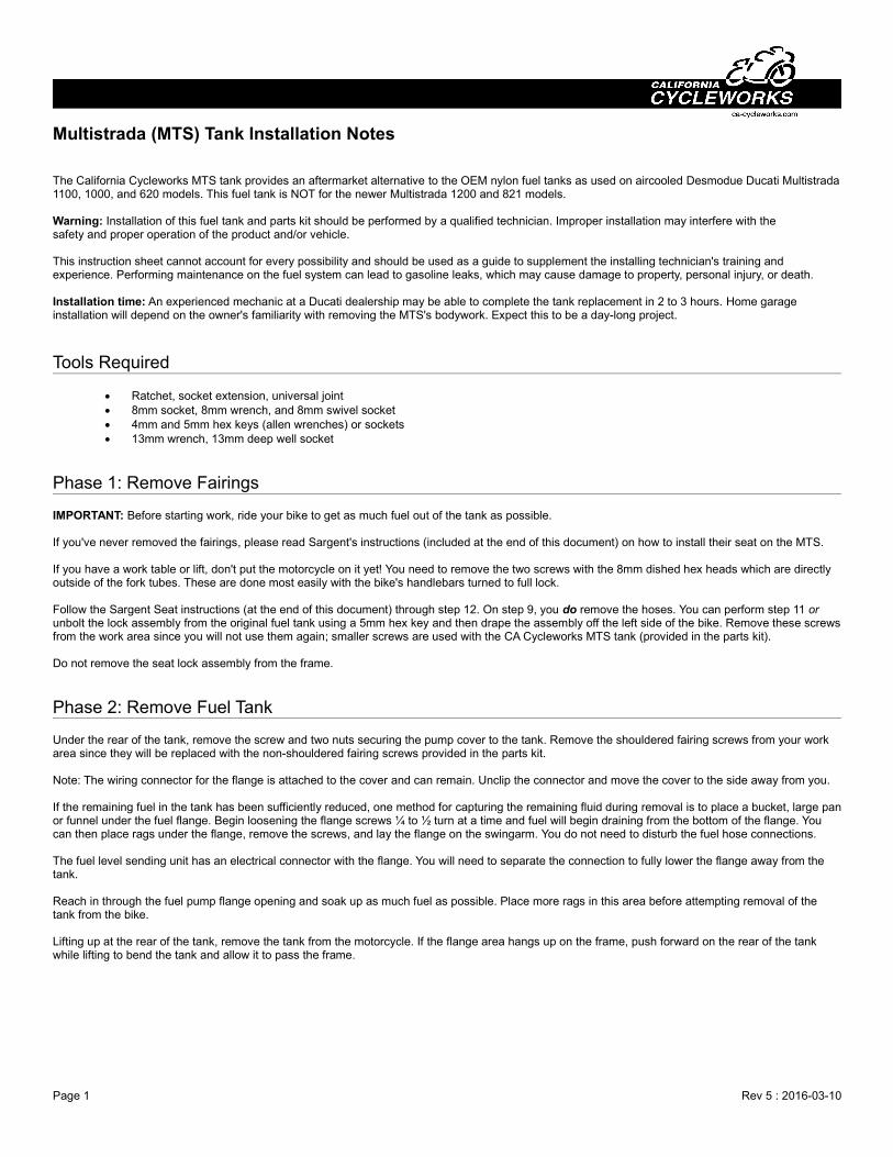
Open the filler cap and remove the screws with a 3mm hex key. Before installing the filler cap to the new tank, install the supplied o-ring onto the filler in addition to the original o-ring as shown:
Place the filler cap on the new MTS tank and slowly and evenly tighten the 5 screws. You will see the o-ring sealing between the filler cap and the tank surface.
Remove the seat from your original tank and fit the seat onto the new tank rear first, spreading the front of the seat while lowering into place. Turn the tank (with seat) over. Use the supplied MTS Seat Bolt kit to affix your seat to the new tank. The longer bolts are for the front two mounts and the shorter bolts are for the rear two mounts. Place the screws through the special caps so that the hex head of the screw fits into the cap recess. Look through the holes in the tank to sight the seat's threads and begin threading the bolts into the seat. Leave all four bolts loose until all are threaded. Now tighten the seat bolts by hand, and then another ¼ to ½ turn using the special tool.
Use an 8mm wrench or socket to remove the four screws of the fuel level sending unit. Reach in the fuel flange area to help guide the wiring out of the tank while lifting up on the sending unit. Do not force anything; the wires become stiff and may break. When installing on the new tank, reach through theflange area to help guide the wires to the back of the tank. The four mounting screws are M6x1.0 threads and torque spec is 6 ft-lb or 72 in-lb. Caution: Medium force on a wrench can easily surpass the recommended torque value.
Note the orientation of the passenger seat mounts. Straighten the forward tabs on them and transfer to the new tank. Tighten the screws with the mounts all the way forward.
Page 2 Rev 5 : 2016-03-10
Multistrada (MTS) Tank Installation Notes
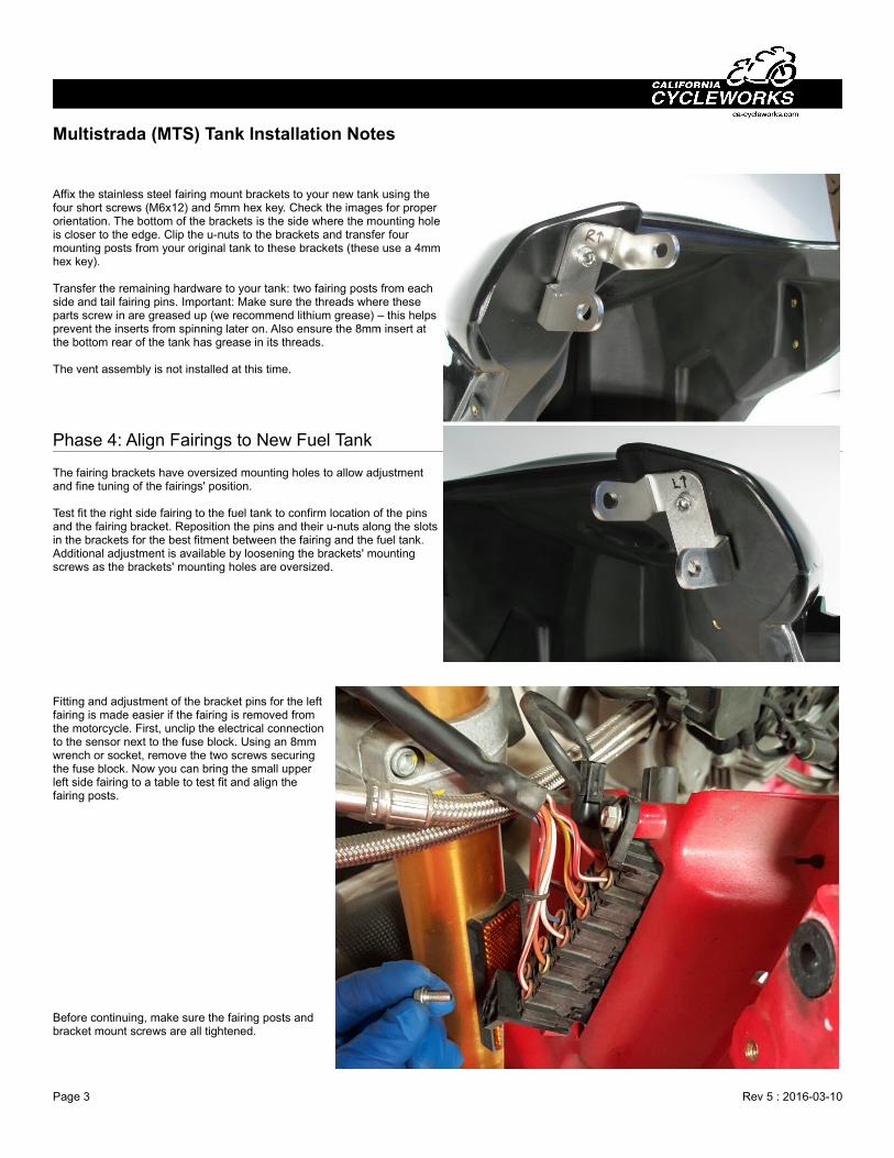
Affix the stainless steel fairing mount brackets to your new tank using the four short screws (M6x12) and 5mm hex key. Check the images for properorientation. The bottom of the brackets is the side where the mounting holeis closer to the edge. Clip the u-nuts to the brackets and transfer fourmounting posts from your original tank to these brackets (these use a 4mmhex key).
Transfer the remaining hardware to your tank: two fairing posts from eachside and tail fairing pins. Important: Make sure the threads where theseparts screw in are greased up (we recommend lithium grease) – this helpsprevent the inserts from spinning later on. Also ensure the 8mm insert atthe bottom rear of the tank has grease in its threads.
The vent assembly is not installed at this time.
Phase 4: Align Fairings to New Fuel Tank
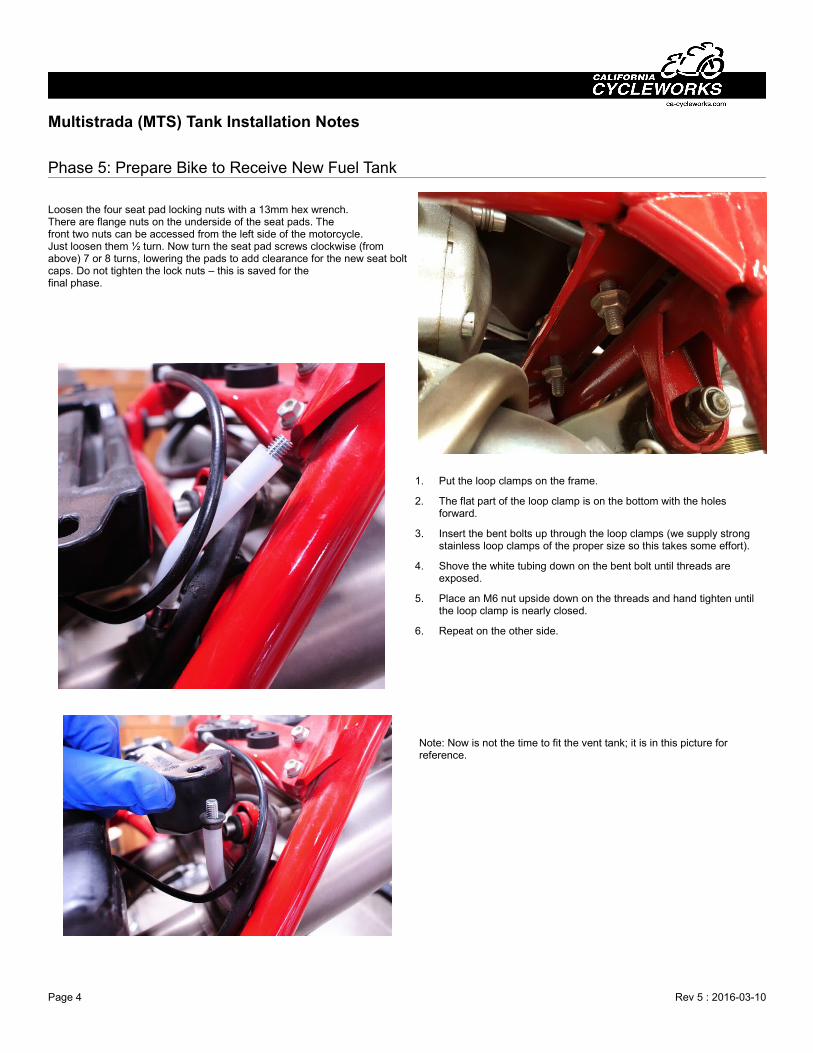
The fairing brackets have oversized mounting holes to allow adjustmentand fine tuning of the fairings' position.
Test fit the right side fairing to the fuel tank to confirm location of the pinsand the fairing bracket. Reposition the pins and their u-nuts along the slotsin the brackets for the best fitment between the fairing and the fuel tank.Additional adjustment is available by loosening the brackets' mountingscrews as the brackets' mounting holes are oversized.
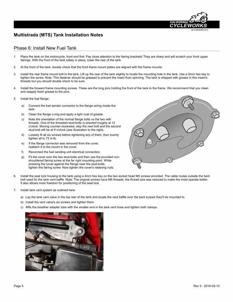
Fitting and adjustment of the bracket pins for the leftfairing is made easier if the fairing is removed fromthe motorcycle. First, unclip the electrical connectionto the sensor next to the fuse block. Using an 8mmwrench or socket, remove the two screws securingthe fuse block. Now you can bring the small upperleft side fairing to a table to test fit and align thefairing posts.
Before continuing, make sure the fairing posts andbracket mount screws are all tightened.
Page 3 Rev 5 : 2016-03-10
Multistrada (MTS) Tank Installation Notes
Phase 5: Prepare Bike to Receive New Fuel Tank
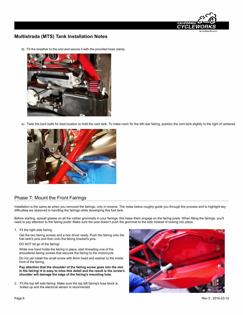
Loosen the four seat pad locking nuts with a 13mm hex wrench.There are flange nuts on the underside of the seat pads. The front two nuts can be accessed from the left side of the motorcycle. Just loosen them ½ turn. Now turn the seat pad screws clockwise (fromabove) 7 or 8 turns, lowering the pads to add clearance for the new seat boltcaps. Do not tighten the lock nuts – this is saved for the final phase.
1. Put the loop clamps on the frame.
2. The flat part of the loop clamp is on the bottom with the holes forward.
3. Insert the bent bolts up through the loop clamps (we supply strong stainless loop clamps of the proper size so this takes some effort).
4. Shove the white tubing down on the bent bolt until threads are exposed.
5. Place an M6 nut upside down on the threads and hand tighten until the loop clamp is nearly closed.
6. Repeat on the other side.
Note: Now is not the time to fit the vent tank; it is in this picture for reference.
Page 4 Rev 5 : 2016-03-10
Multistrada (MTS) Tank Installation Notes
Phase 6: Install New Fuel Tank
1. Place the tank on the motorcycle, front end first. Pay close attention to the fairing brackets! They are sharp and will scratch your front upper fairings. With the front of the tank safely in place, lower the rear of the tank.
2. At the front of the tank, double check that the front frame mount plates are aligned with the frame mounts.
3. Install the rear frame mount bolt to the tank. Lift up the rear of the tank slightly to locate the mounting hole in the tank. Use a 5mm hex key totighten the screw. Note: This fastener should be greased to prevent the insert from spinning. The tank is shipped with grease in this insert's threads but you should double check to be sure.
4. Install the forward frame mounting screws. These are the long pins holding the front of the tank to the frame. We recommend that you clean and reapply fresh grease to the pins.
5. Install the fuel flange:
a) Connect the fuel sender connector to the flange wiring inside thetank.
b) Clean the flange o-ring and apply a light coat of grease.
c) Note the orientation of the normal flange bolts vs the two withthreads. One of the threaded stud-bolts is oriented roughly at 12o'clock. Moving counter-clockwise, skip the next bolt and the secondstud-bolt will be at 8 o'clock (see illustration to the right).
d) Loosely fit all six screws before tightening any of them; then evenlytighten all to 72 in-lb.
e) If the flange connector was removed from the cover,reattach it to the mount in the cover.
f) Reconnect the fuel sending unit electrical connection.
g) Fit the cover over the two stud-bolts and then use the provided non-shouldered fairing screw at the far right mounting point. Whilepressing the cover against the flange near the stud-bolts, tighten the fairing screw. Now tighten the cover's retaining nuts.
6. Install the seat lock housing to the tank using a 4mm hex key on the two socket head M5 screws provided. The cable routes outside the bentbolt used for the tank vent baffle. Note: The original screws have M6 threads; the thread size was reduced to make the mold operate better. It also allows more freedom for positioning of the seat lock.
7. Install tank vent system as outlined here: a) Lay the tank vent valve in the top rear of the tank and locate the vent baffle over the bent screws they'll be mounted to.
b) Install the vent valve's six screws and tighten them.
c) Affix the breather adapter tube with the smaller end in the tank vent hose and tighten both clamps.
Page 5 Rev 5 : 2016-03-10
Multistrada (MTS) Tank Installation Notes
d) Fit the breather to the end and secure it with the provided hose clamp.
e) Twist the bent bolts for best location to hold the vent tank. To make room for the left rear fairing, position the vent tank slightly to the right of centered.
Phase 7: Mount the Front Fairings
Installation is the same as when you removed the fairings, only in reverse. The notes below roughly guide you through the process and to highlight key difficulties we observed in handling the fairings while developing this fuel tank.
Before starting, spread grease on all the rubber grommets in your fairings; this helps them engage on the fairing posts. When fitting the fairings, you'll need to pay attention to the fairing posts: Make sure the post doesn't push the grommet to the side instead of locking into place.
1. Fit the right side fairing.
Get the two fairing screws and a hex driver ready. Push the fairing onto thefuel tank's pins and then onto the fairing bracket's pins.
DO NOT let go of the fairing!
While one hand holds the fairing in place, start threading one of theshouldered fairing screws that secures the fairing to the motorcycle.
Do not yet install the small screw with 8mm head and washer to the insidefront of the fairing.
Pay attention that the shoulder of the fairing screw goes into the slotin the fairing! It is easy to miss this detail and the result is the screw'sshoulder will damage the edge of the fairing's mounting hole.
2. Fit the top left side fairing: Make sure the top left fairing's fuse block isbolted up and the electrical sensor is reconnected.
Page 6 Rev 5 : 2016-03-10
Multistrada (MTS) Tank Installation Notes
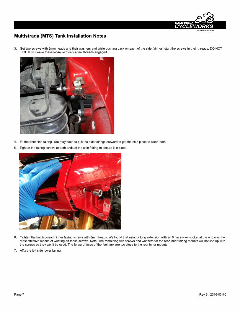
3. Get two screws with 8mm heads and their washers and while pushing back on each of the side fairings, start the screws in their threads. DO NOT TIGHTEN: Leave these loose with only a few threads engaged.
4. Fit the front chin fairing. You may need to pull the side fairings outward to get the chin piece to clear them.
5. Tighten the fairing screws at both ends of the chin fairing to secure it in place.
6. Tighten the hard-to-reach inner fairing screws with 8mm heads. We found that using a long extension with an 8mm swivel socket at the end was the most effective means of working on those screws. Note: The remaining two screws and washers for the rear inner fairing mounts will not line up with the screws so they won't be used. The forward faces of the fuel tank are too close to the rear inner mounts.
7. Affix the left side lower fairing.
Page 7 Rev 5 : 2016-03-10
Multistrada (MTS) Tank Installation Notes
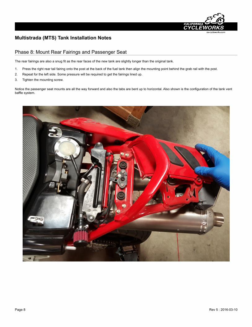
Phase 8: Mount Rear Fairings and Passenger Seat
The rear fairings are also a snug fit as the rear faces of the new tank are slightly longer than the original tank.
1. Press the right rear tail fairing onto the post at the back of the fuel tank then align the mounting point behind the grab rail with the post.
2. Repeat for the left side. Some pressure will be required to get the fairings lined up.
3. Tighten the mounting screw.
Notice the passenger seat mounts are all the way forward and also the tabs are bent up to horizontal. Also shown is the configuration of the tank vent baffle system.
Page 8 Rev 5 : 2016-03-10
Multistrada (MTS) Tank Installation Notes
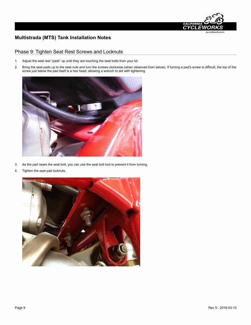
Phase 9: Tighten Seat Rest Screws and Locknuts
1. Adjust the seat rest “pads” up until they are touching the seat bolts from your kit.
2. Bring the seat pads up to the seat nuts and turn the screws clockwise (when observed from below). If turning a pad's screw is difficult, the top of thescrew just below the pad itself is a hex head, allowing a wrench to aid with tightening.
3. As the pad nears the seat bolt, you can use the seat bolt tool to prevent it from turning.
4. Tighten the seat pad locknuts.
Page 9 Rev 5 : 2016-03-10
Multistrada (MTS) Tank Installation Notes
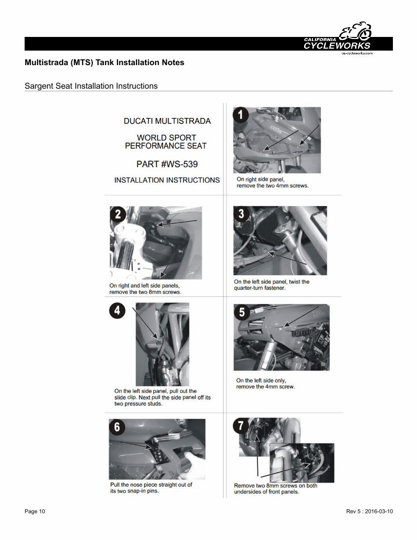
Sargent Seat Installation Instructions
Page 10 Rev 5 : 2016-03-10
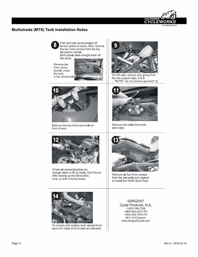
Multistrada (MTS) Tank Installation Notes
Page 11 Rev 5 : 2016-03-10