Embed Size (px)
Citation preview

T.O. 33A1 -1 2-933-1
TECHNICAL MANUAL
OPERATION ANDMAINTENANCE INSTRUCTIONS
MULTIMETER AN/PSM-37
PART NUMBER 910NSN 6625-00-161-4204
O.V.S. INC.F41608-71-D-5442
F41608-90-0-1819
BASIC AND ALL CHANGES HAVE BEEN MERGEDTO MAKE THIS A COMPLETE PUBLICATION.
DISTRIBUTION STATEMENT: Distribution authorized to U.S. Government agencies only for administrativeand operational use, July 1991. Other requests for this document shall be referred to San Antonio
ALC/TIRT, Kelly AFB TX 78241-5000.
WARNING: This document contains technical data whose export is restricted by the Arms Export ControlAct (Title 22, U.S.C., Sec 2751, et seq.) or the Export Administration Act of 1979, as amended. Title 50,U.S.C., App. 2401 et seq. Violation of these export laws are subject to severe criminal penalties.Disseminate in accordance with provisions of DoD Directive 5230.25.
HANDLING AND DESTRUCTION NOTICE: Handle in compliance with the distribution statement and destroyby any method that will prevent disclosure of contents or reconstruction of the document.
PUBLISHED UNDER AUTHORITY OF THE SECRETARY OF THE AIR FORCE
AIR FORCE MJ...3-53-REPRINT 1 JANUARY 1976CHANGE 7 1 JULY 1991

T.O. 33A1-12-933-1
1’""^^^^^^^^^^^^^^^^^^^^^^^B INSERT LATEST CHANGED PAGES. DESTROY SUPERSEDED PAGES
LIST OF EFFECTIVE PAGES |---------------------------NOTE: The portion of the text affected by the changes is indicated by vertical line
miniature pointing: hands.Changes to wiring diagrams indicated by
shaded
Dates of issue for original and changed pages are:
Original 0 31 Jan 76 Change 4 15 Nov 80Change 15 Sep 78 Change 5 10 Jun 81Change 2 15 Jun 79 Change. .6 1 Feb 83Change 3 Aug 79 Change 7 Jul 91
TOTAL NUMBER OF PAGES IN THIS PUBLICATION IS 60 CONSISTING OF THE FOLLOWING:
Page ^Change Page Change Page ^ChangeNo. No. No. No. No. No.
Title 7 5-14 5-16 .4A 7 5-17 .0
.4 5-18 Blank .0
" 0 6-1 41-1 -1-2 4 6-2 Blank. 01-3 6 ^, 4
l-^Blank.................O S Blank \V.\\.V;;;;;:;:.02.2 Blank ;.’;;;.’;;;;;;;;;;. 0 ^^;. ^; ;.;:;..:;.::; 4A-l...................... 4-
3-2 Blank 04-1-4-2 44-2A Added 44-2B Blank 44-3 4.4 44-5 04-6.......................44^6A Added................44-6B Blank................ 44-7 4-8...................04-9 4-11 44-12 ............14-13 44-14......................25-1 75-2 5-3 05-4 4
5-4A Added. 45-4B Blank 45-5 45-6 5-7 0
5-8.......................45-8A 5-8D Added. 45-9-5-11..... .45-12 5-13. 0
#Zero in this column indicates an original page.
ADDITIONAL COPIES OF THIS PUBLICATION MAY BE OBTAINED BY USAF ACTIVITIESIN ACCORDANCE WITH TO. 00-5-2.
USAF
A Change 7

T.0.33A1-12-933-1
TABLE OF CONTENTS
Section Page Section Page
LIST OF ILLUSTRATIONS IV OPERATION INSTRUCTIONS. 4-1
LIST OF TABLES ii 4-1. General 4-14-3. Theory of Operation. 4-1
INTRODUCTION AND GENERAL 4-5. Functional Operation 4-1INFORMATION. 1-1 4-24. Controls 4-10
4-28. Operating Controls 4-111-1. Introduction 1-1 4-35. Operating Procedures 4-121-5. General Information 1-1
V MAINTENANCE 5-1II SPECIAL TOOLS AND TEST
EQUIPMENT 2-1 "’"I- Minimum Performance Standards. 5-15-3. Inspection and Preventive
2-1. General 2-1 Maintenance 5-15-11. Trouble Analysis 5-2
III PREPARATION FOR USE AND 5-16. Repair. 5-4
SHIPMENT. 3-1 5-23. Calibration 5-55-27. Procedures 5-5
3-1. Preparation For Use 3-1 5-42. Overload Tests 5-83-6. Preparation For Shipment. 3-1
VI DIAGRAMS. 6-1
6-1. General 6-1
LIST OF ILLUSTRATIONS
Figure Title Page
1-1. Multimeter AN/PSM-37 ]-21-2. Handle Positions. ’. 1-34-1 Simplified Circuit, DC Volts 20K Ohms/Volt 4-1.4-2. Simplified Circuit, DC Volls 1K Ohms/Volt 4-24-2A. Simplified Circuit, DC Volts -10 Megohms (Part Number 960 only) 4-2A I4-3. Simplified Circuit, DC Volts -10 Megohms (Part Number 910 only) 4-3 |4-4. Simplified Circuit, AC Volts 20K Ohms/Volt 4-44-5. Simplified Circuit, AC Volts- IKOhms/Volt 4-54-6. Simplified Circuit, AC Volts -10 Megohms (Part Number 910 only) 4-64-6A. Simplified Circuit, AC Volts -10 Megohms (Part Number 960 only) 4-6A4-7. Simplified Circuit, AMPS MA 4-74-8. Simplified Circuit, SPECIAL (100UA/100MV) 4-84-9. Simplified Circuit, Ohms 4-94-10. AN/PSM-37 Operating Controls 4-125-1. Troubleshooting Flow Chart 5-3
5-2. Test Equipment 5.8g I5-3. Amplifier Circuit Board Assembly 5-8C5-4. Overload Circuit. 5.8D I6-1. Schematic Diagram, Multimeter AN/PSM-37 for Part Number 910 (911) 6-3 i6-2. Schematic Diagram, Multimeter AN/PSM-37 for Part Number 960 (961) 6-5
Change 4

T.O. 33A1-12-933-1
LIST OF TABLES
Table Title puire
2-1. Test Equipment Required For Servicing ^-15-1. Multimeter tiasic Aeeiiracies 5-’)5-2 AC Frequency Response Accuracies 5-95-;i. Overload Limits .")-}5-4. iVIultinieter Input Impedance Checks 5-105-5. Component Impedance Checks 35-6. Primary Effect of Defective Parts ")-|3
5-7. Test Equipment Required For Calibration 5-17

T.O. 33A1-12-933-1
SECTION
INTRODUCTION AND GENERAL INFORMATION
1-1. INTRODUCTION. To insure that the AN/PSM-37 being usedis covered by this manual, check the
1-2. GENERAL. This technical manual contains operation contract number and part number printedand maintenance instructions for the AN/PSM-37 multime- on the upper right hand corner of the face
I ter, part numbers 910 and 960, manufactured by Q.V.S. Inc., plate. The contract number must end withE. Orange, New Jersey, the numerals -5442 or -0052, or the part
number must be engraved 911 or 961. If1-3. RELATED PUBLICATIONS. T.O. 33A1-12-933-4, none of these numbers are present, thisTechnical Manual, Illustrated Parts Breakdown, manual is not to be used.MULTIMETER, AN/PSM-37.
1-4. PURPOSE. Multimeter AN/PSM-37 is a general L6- MULTIMETER, AN/PSM-37. The multimeter (seepurpose, ruggedized multimeter used for measuring re- figurc Ll) consists of the following items in a self-contained
Bistance, AC and DC voltage, and AC and DC current. The combination case:
maximum values that can be measured are as follows:a. Multimeter, ME-418/PSM-37
a. Voltage 1000 volts, 5000 volts with MX-1410/U b. Test Lead Set, CX-2140A/U for part number 910. |Universal Test Lead Set for part number 960. I
b. Current 1 ampere, 10 amperes with MX-9127/ 9
PSM’37c. Shunt, Instrument, Multirange, MX-9127/PSM-37
c. Resistance 100 megohms n nir,ind. Prod, Test, MX-1410/U
1-5. GENERAL INFORMATION, e. Adapter, Test, MX-9128/PSM-37
1-7. MULTIMETER, ME-418/PSM-37 is the basicWARNING instrument of the AN/PSM-37. It contains a 50 microampere
meter mounted on a plastic panel in a plastic case and con-nected via three selector switches to precision measuring andMultimeter, AN/PSM-37 overload protec-metering circuits. All measurenienta arc made .with the test
tion circuit can fail, causing damage to the,, leads connected to the two lacks at the bottom center of themult meter. Extreme care should be taken
^^^ p FUNCTION, and POLARITYby all users to insure strict adherence totechnical order CAUTIONS and
switches at the appropriate settings. The multimeter is water-
WARNINGS with specific attention totlght wththe cov,e^ on oroff- The, overa," slze ot theequipment is 8 1/2 by 7 by 5 inches and the tota weight isselection of correct function and range, ie(.5 pounds. 1 he accuracies attained are printed on the data
prior to connection to unit under test. r.,.plate ot the multimeter cover. Generally, at room tempera-Failure to comply could result in injuryture, accuracy is within +/-y/c on all DC ranges and +/-4% on allto personnel and/or damage to equipment. AC ranges. he maximum available ohmmeter output volt-ages and currents are printed on the data plate for reference,
...^rpr, particularly for when making in-circuit measurements. The.,.,/ multimeter requires four "AA" size 1.5 volt cells for proper
Electrical measuring capabilities ot the AN/ ooerationPSM-37, models 910, and 960, are essentiallyidentical. For operational purposes T.O. 1-8. The multimeter is protected against accidentally33A1-12-933-1 will be utilized for both applied overload, and against polarity and function selectionmodels, errors, by an overload protection system which opens the
input circuit when necessary. The overload circuit doesnot depend on the battery condition and functions even withthe multimeter in the OFF position.
Change 4 1-1

T.0.33A1-12-933-1
___a___ fe ^^^^0 I-- ^> >-’ 0 J
U ^ r" FUNCTION (C)> ^>’’-pi _JJ) 0 0 0 0
TEST ADAPTER |MX-9128/PSM37 l 1
U \\ B S B \ 8n \\ r"^ | \[l
/^ / /^ ^-1 ULJ’ 5 p tio V Q^
TEST PROD /MX-1410/U /
/ II \ ^ALLIGATOR CLIPS
/ (PART OF TEST LEAD SET)
SHUNT TEST LEAD SET CX-2140A/UMX-9127/PSM-37 (SHOWN) FOR PART NUMBER 910
MULTIMETER UNIVERSAL TESTLEAD SET FOR PART NUMBER960 MULTIMETER
Figure 1-1. Multimeter AN/PSM-37.
1-2 Change 4
T.O. 33A1-12-933-1
/ /7\\ (a/’V/ \y^ nm*>> p’--’-’o MKOI^ oy L\\ ^sss;;;!^ 1’^ if i^^’
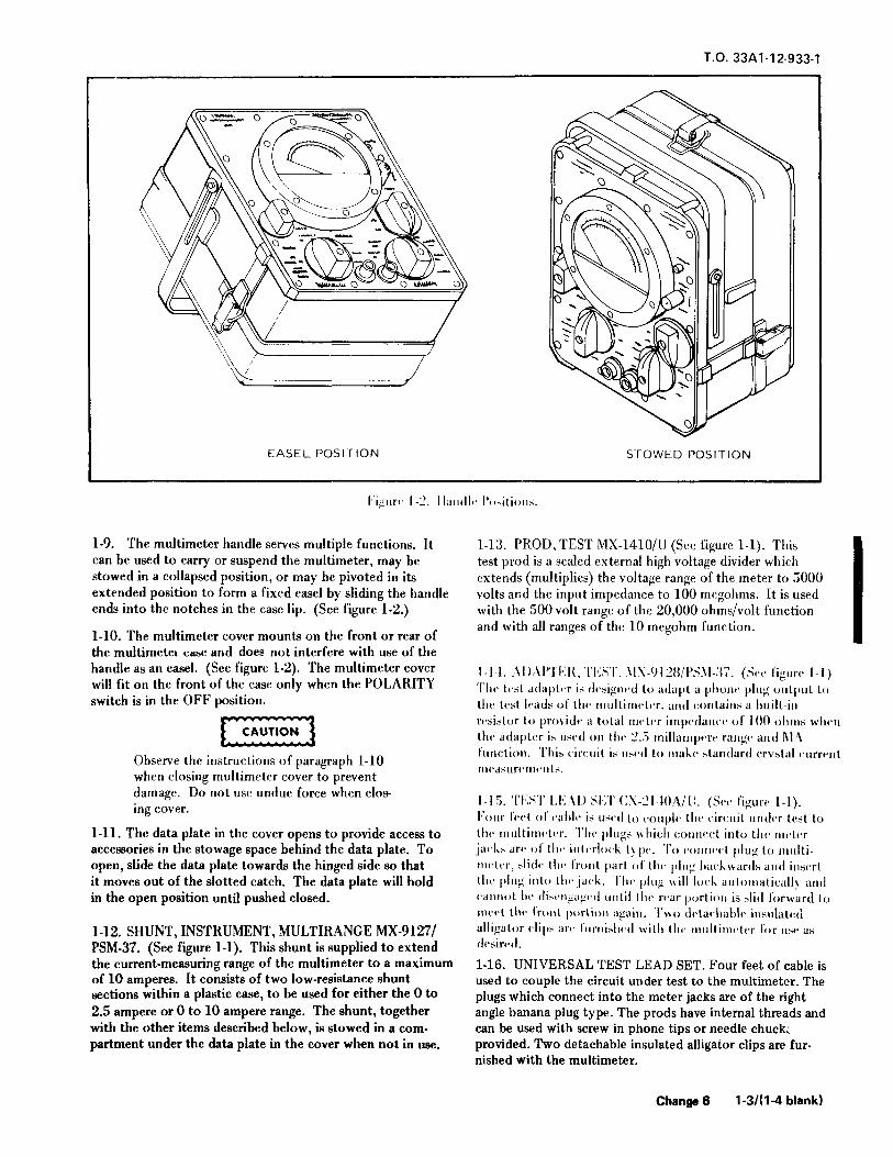
^^ "EASEL POSITION STOWED POSITION
l-’ignre -2. Handle Positions.
1-9. The multimeter handle serves multiple functions. It 1-13. PROD, TEST MX-1410/U (See figure 1-1). Thiscan be used to carry or suspend the multimeter, may be test prod is a sealed external high voltage divider whichstowed in a collapsed position, or may be pivoted in its extends (multiplies) the voltage range of the meter to 5000extended position to form a fixed easel by sliding the handle volts and the input impedance to 100 megohms. It is usedends into the notches in the case lip. (See figure 1-2.) with the 500 volt range of the 20,000 ohms/volt function
and with all ranges of the 10 megohm function.1-1U. 1 he multimeter cover mounts on the tront or rear otthe multimeter case and does not interfere with use of thehandle as an easel. (See figure 1-2). The multimeter cover [.]4 ,\1)APT1’;K, TKST, MX-’JI 28/P.SM-;i7. (See li"nre -I)will fit on the front of the case only when the POLARITY ’[’he ^ adapter is designed lo adapt a phone plug output toswitch is in the OFF position, the test leads of the multimeter, and contains a built-in
jp^^’’^^"’"-"’’""^ rrsislur to provide a tolal incli’r impedance of 100 ohms when\ j lnf’ adapter is used on llir 2.5 millaiiipfre range and MA
function. This circuit is used to make standard crystal currentObserve the instructions ot paragraph 1-10
measurements.when closing multimeter cover to preventdamage. Do not use undue force when clos-
,^ TKST LF.AD SI.;T (;\-2l40A/[;. (See figure l-l).me cover.I-our Icct ol catilf is used lo couple tlif circuit under test to
l-ll. The data plate in the cover opens to provide access to the multimeter. I’lic plugs which connect into the mftrraccessories in the stowage space behind the data plate. To jacks arc of tlir intrrlock type. To connri’l ping to innlti-open, slide the data plate towards the hinged side so that nirlf’r, slidr llir Ironi part of llir plug backwards and insertit moves out of the slotted catch. The data plate will hold thr plug iiilo llir jack. Tlir pliig will lork autoinati<;all\ andin the open position until pushed closed, cannot be disengaged until tin’ rrar portion is slid forward lo
nu’rt llic Ironi portion again. Two ilftarliabic insulated1-12. SHUNT, INSTRUMENT, MULTIRANGE MX-9127/ alligator clips an. liimislicd with llic multimeter lor use as
PSM-37. (See figure 1-1). This shunt is supplied to extend desired.
the current-measuring range of the multimeter to a maximum 1-16. UNIVERSAL TEST LEAD SET. Four feet of cable isof 10 amperes. It consists of two low-resistance shunt used to couple the circuit under test to the multimeter. Thesections within a plastic case, to be used for either the 0 to pings which connect into the meter jacks are of the right2.5 ampere or 0 to 10 ampere range. The shunt, together angle banana plug type. The prods have internal threads andwith the other items described below, is stowed in a corn- can be used with screw in phone tips or needle chuck:partment under the data plate in the cover when not in use. provided. Two detachable insulated alligator clips are fur-
nished with the multimeter.
Change6 1-3/(1-4 blank)


T.O. 33A1-12-933-1
SECTION II
SPECIAL TOOLS AND TEST EQUIPMENT
2-1. GENERAL. The test equipment listed in table 2-1 is
required to service the multimeter. Equivalent item(s) mavbe used it the recommended item is not available.
TABLE 2-1. TEST EQUIPMENT REQUIRED FOR SERVICING
EQUIPMENT NO. FIGURE NO. NOMENCLATURE USE AND APPLICATION
AN/PSM-.J7 or equivalent 1-1 Multimeter Input impedance andcomponent checks
HP6012A or Equiv. DC Power Supply DC Voltage Source
Weston Model 931 DC Milliammeter Current Monitoror Equivalent
Fluke 8300A or Digital VM Monitor SupplyEquivalent Voltage
20980 or Equiv. Test Leads Interconnections
Change 4 2-1/(2-2 blank)


T.O. 33A1-12-933-1
SECTION III
PREPARATION FOR USE AND SHIPMENT
3-’!. PREPARATION FOR USE. :i-~^. (:;!;:( :K i T. Aftrr battcri*-. ar.’ m-tallri). roiiii.-rl
l<--( Irad’. short lo^rtfn-r at tli<- ti|>;-. and ’rt tin’ nnitlini’-irr(’Dr OHM- 1,1’ R NC.TlOV i!\H K\\(;[’:mni 00 i^tLAK
:(-i (;!"\i.:K \1.. (ii, i.n(ir<- \\,’’1’.-’>1 ;i~ i~ J).K k.^cd iti !’, Cln.,.1., (liyi tin- i,\,-rlt)ad circuit lia- IH’I’II -rl liv (irc?-iillit (olil.niirr. Tin’ ;icci-;;-.orir> ,in1 .-(.>\M’ii in (lir >’oiti|mr[iilfiil ,1,1^ i|i,. ,.,;[, |,,-r p,..,.( imiton ,);>() >T]|-.INII_. T!ir nif!..!’ .-)ii>ii)ilii.-fiiiid (lie <(ata ph(r in llir iniif(iiiu’(rr coM.r. t’(ir ii.itli’rn-, ,.,,;(,| iip-,,.alr.in>i ran li<- i;!<- to ITU(! I’ull-.-rul.-. <,r /.ro
;i<).( r,>(^ ,,H)ii- ,,iaiiiial aiv p,i<k^v<l in llir niiH conlaiiK-r ,,|nu,. 1^ lurnin,; tli,. HIM> \1).| knoli a, IK-<-(I<.<I. \\li,.n!1< i-\(rrtial In tlic liniltiiiii.irr r.i.-.r. 1’nll-scalr I- olilailiri). clirrk that ill.’ lllrH-i- roillliuir.. to ivad
;ij>pr().\ii!);i!c)\ liill-scalc vvilli tll<’ I*’ll, \l<l’l’’l >.\Mlcli sri to
\i>u k l\l i) ,1 1)<: and illi lh<’ ^^’\(:l’10^,-^Ml(h.,t lo OilMSSTI). IC>1 V! (\ M ’("’ii ill’- ilin! ’(i(l!<litl<’r ,!in) rriiu>\
llir ali<i\r iK’rti.irinaiK’r i,- ll<l iilit.iilinl, rillicr liir l);)ltrric>ilir Djitrr!!’-.. ulinli arr l<\ifr(l ]ii^( in-.ntr (lie rarldi) (ni^
,] ;ir<’ \vi\>k or iiiiiir<)iii’rl\ iii.-lallrij or iiif >< f’.Hl.l) M) ),-> not(lo^iiri lu’lliin’’ Ihr illaniiiil s’.hn’li i’ firl\\ rrii tin’ rn-nidii-
i)), ilri(! llir Cid’liii] \’.,lll. )n iii)l rut ilrrprr (!ia:i (lir i’iirli)n
<’!<’-(ic<- (ir (j.ini.i^r tn (iai(.’i-n’-. ur iiiaiiiitil in.n i-r’-ull. lli’inoM’ MI^TE(lir iinittiinrtrr (rniii (iic <’;ir!<n ,iin] !,)k’’ lii<’ iiiiilliiiirirri.i\mi(’(. OIK’II flu’ iLil.i nfair ami .ii<’rk llial llir Ii.’Ird ar-
l’i’ ’" ’"ls ^1 u iitK’tKUt <ioi^not (wraic on<’’->.<)rir>;irr ;lll lin!n(lr(!.
tlir HA raM^f ticcausr ui (DC ma\imunt
allowed dhninirtcr output cilrn-ii! ol ~i rnil-:;-!. IJA’l’TKH’t IX^T \Li. \’!’)0\. l-’nihiu tlir i(!.-(riif!!i>!i.’. iiatiipcrc^.))) ihc dala plutr In ni-lall lialtrrir,-. ’1’lir l>;it(rn r())n();if((ti<’titliu^r;i).^r(l in;irkiii^-li<mn^ tin. i>r[’,’r ]>;Ut.T\ (K.laritii-. ’!’)) 3-6. PREPARATION FOR SHIPMENT.)iiii!lnflrr i.s jirntrrli’i! ;i^,)ins! ;ircii)riit;i! n’K’r-c !iitli’f’\
lii-’tallutiiin !>iil will fie! tuin-lnin (>ro(’r)i inilr.^ .i)) liutlrrii-. :{-". Knuovc lh<’ batteries anif pa^k the timftiinrtcr in;irr [>ri’j’rh i!i.’l;il!<’<i. ;icford;iin’" \villi currfiit packing and shipping dirf(;liv<;s,
1 .3-4 \. \H’:(:11A\!(:A1. /.KRO. Tlic in.-<-l>,.iin.,al /,cro dd\wi-im’lil scn-w i;. locatrd ul. I.IK’ Ixiltoni (.(iitrr i)( tile tl.(’t<’r
iianrl just alxn’r li>>’ (t)iiii(in^ srrfu. Adju.st llif niclcr l(r
tTirrliutiical /.cro ii’s (urniiip: (in- fcrcw with a sinall standard-rrwdrivcr.
Change 3-1/(3-2 blank)


T.0.33A1-12-933-1
SECTION IV
OPERATION INSTRUCTIONS
4-1. GENERAL, discussion of the theory of operation will therefore bedivided into the individual circuits resulting from each com-
4-2. This section contains the theory of operation and bination of switch settings. The complete schematic diagramoperating procedures for the multimeter, is shown in figure 6-1.
4-3. THEORY OF OPERATION. 4-5. FUNCTIONAL OPERATION.
4-4. INTRODUCTION. The multimeter is a precision 4-6. DC VOLTAGE 20,000 OHMS PER VOLT. With
general-purpose test instrument which combines the the FUNCTION switch set at VOLTS 20K n/V, and the
( functions of an AC and DC voltmeter (with 10 Megohm, RANGE switch at any position, the circuit reduces to the20K fl /V and 1K 0 /V meter sensitivities), an ammeter, simplified diagram shown in figure 4-1. Resistors R35and an ohmmeter. The settings of the FUNCTION, through R43 comprise the 20,000 ohms-per-volt seriesRANGE, and POLARITY switches control the charac- resistance string. The series resistance values are chosenteristics and range of the meter circuit, and the to provide the required ranges.
+ 0-------------------------]iioool$ R35, R36
NOTE 500i1-----o-o-4OVERLOAD CIRCUIT DISCONNECTED c^ ^ABOVE 50 VOLT RANGE (SWITCH CON- ^ R37NECTIONS OMITTED FOR CLARITY), y^<OVERLOAD PROTECTION ABOVE 50 p AVOLTS IS PROVIDED BY THE VALUES IAND WATTAGE RATINGS OF SELECTED > 030COMPONENTS. >
^50 \OVERLOAD ^CIRCUIT S
10 \r n 0-^0---L. CR^\. 2 ^ ^^-yvnniT^ CBI -^CR1 Y VR1 0-^-4
^R56 ^ R42, R43
VR4 "X^QI \//\ ^ a (/)
"Vi__ CR3 X
M.C12 :
-------< i----i i-----I-----t--_--__L---^-__J
Figure 4-1. Simplified Circuit. DC Volts 20K Ohms/Volt
Change 4 4-1
T.O. 33A1-12-933-1
o-----------------------9--||ioool
NOTE ______ sooj ^"^OVERLOAD CIRCUIT DISCONNECTED " * \,ABOVE 50 VOLT RANGE (SWITCH CON- -u > RQ-RIO
NECTIONS OMITTED FOR CLARITY). > 3 "i"
OVERLOAD PROTECTION ABOVE 50 ^250^VOLTS IS PROVIDED BY THE VALUES TAND WATTAGE RATINGS OF SELECTED >COMPONENTS. ^R13-R15
0^4CARLOAD ^,^----.---------, ^
o___I-, ^-./K ^2 ^R18, R19
(- -^TTf> r^cB T0 N^ -’> ^ R20
CR1 ’’</- VR1 5 <
R56 ^ R21/22< R23 ^R25VR4 <1 JL^
Ql \^< ^ 3ECR3 R26-R34 (/ VMl
L--_---*----<1----J
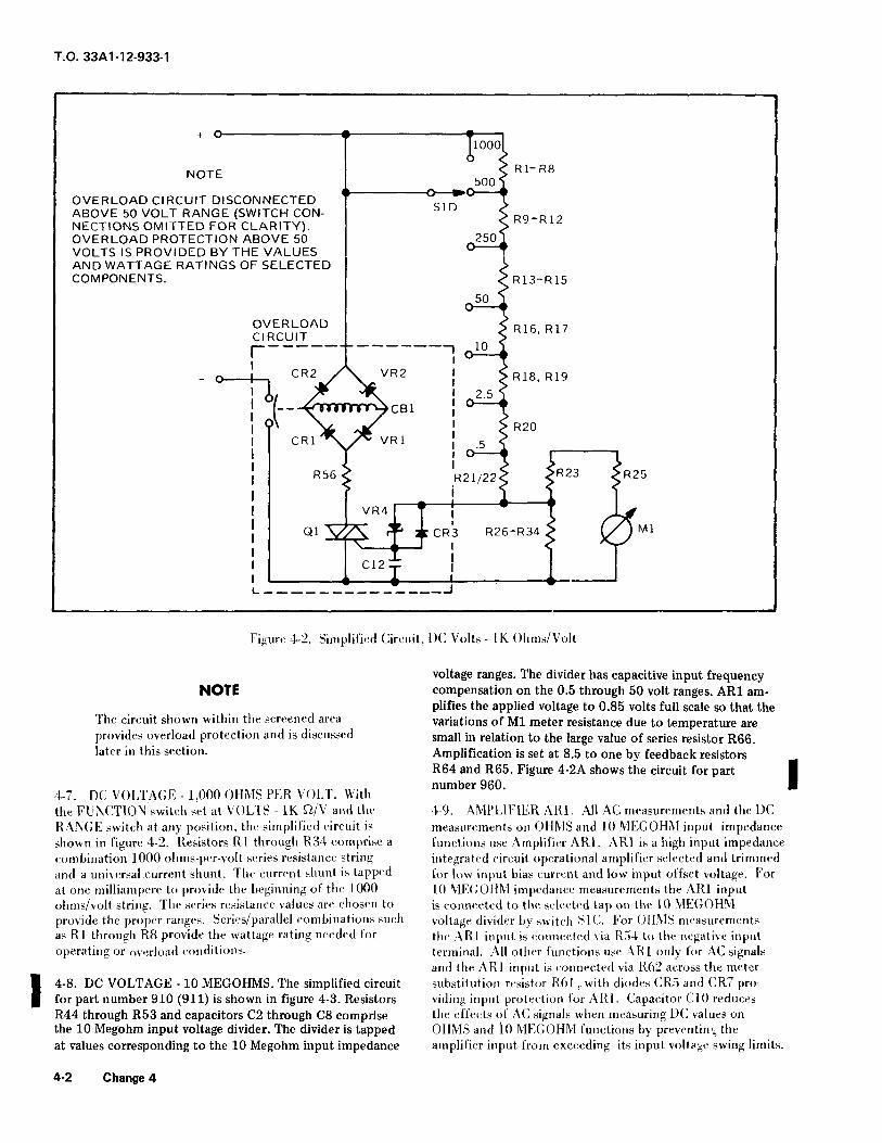
Figure 4-2. Simplified Circuit, DC Volts 1K Ohms/Volt
voltage ranges. The divider has capacitive input frequencyNOTE compensation on the 0.5 through 50 volt ranges. AR1 am-
plifies the applied voltage to 0.85 volts full scale so that theThe circuit shown within the screened area variations of Ml meter resistance due to temperature areprovides overload protection and is discussed small in relation to the large value of series resistor R66.later in this section. Amplification is set at 8.5 to one by feedback resistors
R64 and R65. Figure 4-2A shows the circuit for part I4-7. DC VOLTAGE- 1,000 OHMS PER VOLT. With
number 960.
the FL’NCTION switch set at VOLTS 1K ^2/V and the 4-9. AMPLIFIER AR1. All AC measurements and the DCRANGE switch at any position, the simplified circuit is measurements on OHMS and 10 MEGOHM input impedanceshown in figure 4-2. Resistors Rl through R34 comprise a functions use Amplifier AR1. AR1 is a high input impedancecombination ]000 ohms-per-volt series resistance string integrated circuit operational amplifier selected and trimmedand a universal .current shunt. The current shunt is tapped tor low input bias current and low input offset voltage. Forat one milliampere to provide tile beginning of the 1000 10 MEGOHM impedance measurements the AR1 inputohms/volt string. The series resistance values are chosen to is connected to the selected tap on the 10 MEGOHMprovide the proper ranges. Series/parallel combinations such voltage divider by switcli SIC. For OHMS measurementsas Rl through R8 provide the wattage rating needed for the AR1 input is connected via [{54 to the negative inputoperating or overload conditions, terminal. All oilier functions use AR1 only for AC signals
and the AR1 input is connected via R62 across the meter
1 4-8. DC VOLTAGE -10 MEGOHMS. The simplified circuit substitution resistor R61, with diodes CR5 and CR7 profor part number 910 (911) is shown in figure 4-3. Resistors viding input protection for AR1. Capacitor CIO reducesR44 through R53 and capacitors C2 through C8 comprise tlie effects of AC signals when measuring DC values onthe 10 Megohm input voltage divider. The divider is tapped OHMS and 10 MEGOHM functions by preventing theat values corresponding to the 10 Megohm input impedance amplifier input from exceeding its input vollage swing limits.
4-2 Change 4

T.0. 33A1-12-933-1
| C14= I ^ R45 |
| C15 r : > R69 |
I ^ R70 IC4 Z Z. ^ R47
C5^: ^ ^ R48
i-------------0^--0-< 1-------- ^^^<’ slc AR1 ">--->---------IC6_^ ^ R49 ^^
50
^ R66 ^C7 r 250 R65 ^S R51 ^c8 *---------0 R64 ^i ’ (/!> R52 Tf 1000 Ml
T------ cio
^ R53
Figure 4-2A. Simplified Circuit, DC Volts -10 Megohms (Part Number 960 Only)
Change 4 4-2A/(4-2B Blank)


T.0.33A1-12-933-1
+0---------------( ----.
C2 Z Z <^, R44
C3 1 : > R45
S3E
ci r :R46
> .5
C4 Z I R47
^ 2.5
C5 ^ ^ R48
10 ^i---- --------04--0-< ^s.
slc ARl S------------,C6 Z Z. R49 ^^
50
R66 SR50 <, <
C7 ^ 250 R65 <--------0 [
R51 ^CK~" 500 ^-r- --------0 R64 ^R52 ^-/
^ 1000 VII--------- C10
R53
Figure 4-3. Simplified Circuit, DC Volts -10 Megohms (Part Number 910 Only)
Change 4 4-3

T.O. 33A1-12-933-1
C10 is always supplied by a high resistance so that a high when Cl is bypassed for DC measurements.RC constant results. The high input impedance of AR1 doesnot load the input circuits and thus does not affect the 4.]] ^ VOLTAGE 1000 OHMS PER VOLT With theaccuracy. AR1 is encapsulated and requires no adjustment. POLARITY switch at AC and the FUNCTION switch at
VOLTS 1K ^2/V, the simplified circuit is shown in figure4-10. AC VOLTAGE 20,000 OHMS PER VOLT. With the 4-5. This circuit is essentially the same as the 20K n/VPOLARITY switch at AC and the FUNCTION switch at function, except that the 1K H/V resistance string of R]VOLTS 20K n/V, the simplified circuit is shown in figure through R23, with R25 in series, has been switched in as4-4. Diodes CR8 through CR11 form a full-wave bridge the input to AR1.circuit with Ml connected so that all current through tlie
^^"z^^^^r’’ 412, ACVOLTA.GE1MEGOHMS- wlt he roLAR"vj, r>f) i, switch at AC the simplified circuit for part number 910 is asfeedback voltage across Rod by passing through R63 to
TI ^OCQ shown in figure 4-6. Resistors R44 through R53 (except R46)ground. he value of Rod is such that scale readings ofr>,>c and capacitors C2 through C8 comprise the input
sinusoidal signals are equal to the KMS value even though,- impedance voltage divider. Capacitor Cl blocks DC voltages.the actual detection circuit measures average values. ,r. ,."..p pi i-i r\r i (Resistor R46 limits the discharge current when Cl isCapacitor Cl serves to block DC voltage when making .
bypassed for DC measurements). The simplified circuit formeasurement of AC signals. R46 limits the discharge current 1, ,.’part number 960 is shown in figure 4-6A.
+ 0-------------f-------------f---|110001
^ R35, R36
500 ii--------0-’0--
S1E Z<> R37
NOTE250^0--\ OVERLOAD CIRCUIT DISCONNECTED ABOVE 50
^ VOLT RANGE (SWITCH CONNECTIONS OMITTED
^ Kja FOR CLARITY). OVERLOAD PROTECTION ABOVE50 \ 50 VOLTS IS PROVIDED BY THE VALUES AND0--4 WATTAGE RATINGS OF SELECTED COMPONENTS.
OVERLOAD ^ R39CIRCUIT >^--_-------------^ ^0 <
0-J-, CR./\, R2 ^ R40
A/ /" ^\ p2-5 ! i^
L-^mrmr^ CBI 0 T ^^^ CRS CR9
^ ^ ZR41 ARI,>---<-M--f-N-
cRi V vRi o-^-l r" >^ r ^^R56 ^ R42, R43 X’ / Ml
i-i i----y-w^-i -M---N-’VR4 L R62 CR10 CR11
QiSS ^ ’- ^ ^ R61___ 1--------0-^0-------------IN--- --’CR3 \ \---- S3A J
________^
C12: :_____I^ ^
$ R63
I----------------J CR7 CR5 [
Figure 4-4. Simplified Circuit, AC Volts 20K Ohms/Volt
4-4 Change 4

T.0.33A1-12-933-1
[loool
^ R1-R8 NOTE500^0 i--------0--’0-- OVERLOAD CIRCUIT DISCONNECTED ABOVE 50
S1D .> VOLT RANGE (SWITCH CONNECTIONS OMITTED
^ R9-R12 FOR CLARITY). OVERLOAD PROTECTION ABOVE250 f 50 VOLTS IS PROVIDED BY THE VALUES AND0-- WATTAGE RATINGS OF SELECTED COMPONENTS.
n ^R13-R150^4
OVERLOAD ^n,gCIRCUIT ^ R16, R17
r ------; o^CR2 /X VR2 ^R18, R19
^-^Tmr^ cBi ^-{ I--- ^s. CR8 CR9
<>\ \^ ^ ^ R20 AR1 >-----li--N---T---M--CR1 ’\ .?^ VR1 5 ^ ^^ / ^^^> ^ ^D 0"3 ^ r\*’0
R56 ^ R21/22^ <"23 Z |T^_4 f-’W^- -M--1-N-i
VR4 " I R62 CR10 CR11
^ SS 3C’ "CR3 R26-R34^ ^R61____ 1--------0-->0--------------I-"-<C__,i__ <. < S3A
C12:: CR5^p ^R63-; ;CR7 (
l-_----___------J
--------------( ----( i---< i---i -------------------------1
Figure 4-5. Simplil’icd Circuit, AC Volts K Ohms/Volt
4-13. AMPERES MILLIAMPERES. Will) the FUNCTION 4-15. OHMS. With the FUNCTION switch at OHMS, theswitch at AMPS MA/PULSE MA and the RANGI^ switcli simplified circuit is shown in figure 4-9. Taps from the cur-at any position, the simplified circuits are shown in figure rent shunt and scries string (Rl through R34) provide Rxl4-7 for both AC and DC modes. The current shunt is througli RxlOK resistance scale standards. The RxlOOKtapped at values from 100 microamperes to one ampere to resistance scale standard is taken from tlie 10 MEGOHM di-provide the ranges for the MA and SPECIAL functions. For vider (R44 througli R53). Amplifier AR2 serves as a regu-pulsating direct currents, with pulse amplitudes not greater lated bipolar voltage source tor OHMS functions. Ul is a
than 20 times the full-scale value of the selected range and a field effect transistor (FET) connected as a variable current
repetition rate from20Hzto 30 KHz, the multimeter indi- source and controlled by OHMS ADJUST potentiometercates the average value of the current within the range and R68. L delivers constant current to R60 regardless of ac-
aecuracy limits specified for DC current, tual battery voltage and generates either +95 or -95 milli-volts across R60, depending on whether the current source
4-14. SPECIAL. With the FUNCTION switch at SPECIAL is connected to the positive or negative battery terminal. Forand the RANGE switch at any position, the simplified circuits ""’fy g’""; K59 is a series feedback resistor. CR4 and CR6are shown in figure 4-8 for both AC and DC modes. The in conjunction with CR5 and CRT protect /\R2 from inputcircuits shown are essentially the same as those shown for the overloads if a hot circuit is measured instead of a passiveAMPS-MA/PULSE MA function (figure 4-7) except that R25 resistance.is no longer in series with the meter input but has becomepart of the shunt string.
4-5

T.0. 33A1-12-933-1
+0---------------i ----i
C2 1. r <^ R44
C3 Z : >R45’>
i-----9
f S3E
ci ZIR46
s .5---------0
C4 Z. 1 R47
^ 2.5.------< --------0
C5 Z I. R48
10 ^^s.--------0"--0--- -S. CR8 CR9
^^C ARl ^?-------N------M--I
C6 1.1. R49 .^-^ /">^_^-^ 4’1’-H--*-N--<
CR10 CR11"50 |--------^_^-------- ______1
C7>
250 S3A <---------0 ^R63R51
500C8 ---------0
R52
1000---------0
R53
Figure 4-6. Simplified Circuit, AC Volts -10 Megohms (Part Number 910 Only)
4-6 Change 4

T.0.33A1-12 933-1
Sfti8S8SSS5S3S&5SE5S83S83SSSSSSSS^Sf^^5SffiSS5S38SSS!^
+0---------- ------< i-----I
ci4 rz ^ R45
>----
C15 1 ; > R69o ^
C16 ^ ^^ R70
C4 Z. 1. S R47
12-5
C5 Z 1 ^ R48
--------------OM--0--- ^ss^ CR8 CR9J SIC AR1 .>-----I--N------M--I
C6 1: Z ^ R49 ^- y^f
\ ^1J I--N--^--N-<S CR10 CR11< R50> I--------0---0--------------
C7 (" 250 S3A J4--------0 ^R63
^R5109" T 500"--,- *--------0
^ R52
f 1000
f------
^ R53
Figure 4-6A. Simplified Circuit, AC Volts -10 Megohms (Part Number 960 Only)
Change 4 4-6A/(4-6B blank)


T.0.33A1-12-933-1
5-s ’< rs 3,- U Q;
"CV-^ ^/s^
0
u u
,<roin
A "/ \ i3/ S \ 5/ < \ I
L________ in <a- _ju _i
1--T---T-N-’ 2
"J <^CMS.10 M
^ Q <D; T"’CM ro / ^o Q;a in [ a: ^I-------A^-----------o-6-^AA/^-----< "?
3 ^^ ^------| S^ ^OCI-CC <
^/NA^-V^A/^^V^AAA^V^A^A/V^^^^ =<!> <!> <1 <!> A d |
’5-
^in ^ r-
7 CN* 9^ -^q |---------------^-------------------------------------(R)-----------I -G0: ’J< ^^! ^^-I sl^G ^l-^
s ^AAAl^A/^AAA^AAA-t-AV^A^6 0 0 6 0 6 w
"’ -------------------HJI’Zl- 0:co f -i, a 11 LJ
^ |1gR. tlh |
S < 2 S ^ <
s 3 i s| > > u ^----^-X<^]_^L i
J3 5 gQ:
3
^ r^-------’oo ^F____,..__..____________*_____________________I_________________________
4-7

T.0.33A1-12-933-1
8"I010: 3 ( ro
0 S
^1^ 5u
<n(/)
-------- in 1.a
:----r^ ’M <>D ^^ ’ f S ^ ICO CC Q: ^,---0 XO---i^^-----------^---I ^
l------------/\/V------------< -;^^^.---------- ^CM I fl ^;0: I- 0: -;
-^- tina^ =,.N I ro ;--0:1- n:
>-------------^/S/^/^------------i
m ^Q: (r
^ Tr j*^r’!
Oh- S ’T S^5 <-> u
^ ^s------I" L J---- -1
o
+
4-8

T.0.33A1-12-933-1
zCTl CO Q cf 0
^ ri Fo: a ^ ?! !=’< t/1
u^ 0-A ^/s\ ai <sz/ a- \ ^-/ < \ zZ_--_A uj $^---’ og
Z LO
i^-----!--ooU3CC
IDQ;
--ws<-i 2
^^1-^- I10 ^.r
e i Is os ^kj
(/1 T? ^I-M--I I--VsA/--( >-AA^-< h0-0-i u^: g-^ Q. L-i .6
10 ’0 _| COQ; ^z oi
^-J A HH p :g A . ^ i
/ < \ u
.^--11-in < oa < u
r n ^ 1
5. ) 5 ^rW^TlH^T !>4^! ^ J^" 1< *C i ^^ R ^ < ^S Q ^^’/^S S ^" ^ " Y " L l^LJL^L Jai ^ ,-0 0-------------( (AA^WS^SAA^NAAd (AAAr^-A^V-1
^5L-_ --J^tm
6 6 ^i< ac (r
^ Change 4 4-9

T.0.33A1-12-933-1
4-16. OHMS LP. With the FUNCTION switch in the utilized for overload switching. Resistor R39 limits currentOHMS LP position, the maximum input voltage to AR1 is into AR1 and AR2 for protection from damage which would95.3 millivolts, wliich is amplified by AR1 to 0.81 volts full otherwise result from reverse battery insertion.scale. Ml reads full scale under these conditions because R67shunts R66 for ohms measurements. AR2 serves as a unity 4-24. CONTROLSgain voltage follower connected to the positive multimeterterminal and delivers 95 millivolts regardless of the current 4-25. RANGE SWITCH. Sl is the RANGE selector switchdelivered, and is used to select the correct measurement range. The
proper range for voltage or current is normally that wliich4-17. OHMS STD. The STD OHMS maximum input gives the greatest scale deflection without going overscale.voltage is 0.81 volts and the AR1 gain is set to unity DC The proper ohms range is normally that which produces again. By placing feedback capacitor Cll between R64 and reading within the wide-band part of tlie green arc on meter
| ground AC gain remains at 8.5 to one for amplifier stability Ml. Pulsating signals may require reading on ranges abovesince Cll does not block AC feedback currents from ground, the value obtained above.AR2 is set at 8.5 to one gain by feedback resistors R58 andR59 and delivers 0.81 volts to the positive multimeter a. Sl A is the OHMS range selector. It connectsterminal, metering neutral througli standard resistances of 20, 200,4-18. OVERLOAD PROTECTION. 2K, 20K, 200K, or 2 Meg ohms to llie negative input ter-
minal. It also grounds the S2C side ol R54 in position 7 to4-19. Overload protection is provided for all input circuits. ^^ erroneous readings and in position of STD OHMS toThe 10 MEGOHM function and the 20K O/Volt and 1K ^^^,-ange because its output current would exceedSl/Volt functions above the 50 volt range are inherently pro- ^g^ allowedtected by tlie values and wattage ratings of the componentsused and do not trigger the overload relay under any cir- I, g] ^ ,s the MA range selector switch. It connectscumslances. thg positive input terminal to taps on llie universal current
shunt which are 400, 80, 20, 4, 0.8, 0.4, or 0.2 ohms above4-20. Fhe SPECIAL, MA, and OHMS functions all use a
.’. ’, the negative input terminal, lor full scale deflections of 0.5common overload circuit, whereby the positive multimeter
througli 1000 milliamperes respectively. lie circuit is so
^Tallsconn^ to o’ ve f cl ^P"8^ arranged that llie contact resistances o’f CBI, S1B, S2F, S2A,
^’^P2’ ^Rl’ r1 VR2’ ?"" via R56 to thyristor -d S2B do not affect measuring accuracy.(iRIAC)Ol. When 01 is blocking, no current flows throughit and the relay coil has insufficient current to trigger. The ,. ] (j is the 10 MEG^ input impedance range selec-voltage blocked by Ql is passed via limiting resistor R55 tor switch. It connects the input to AR1 via S2C to thethrougli zener diodes VR3 and VR4, which set a minimum appropriate tap on the 10 MEG^ voltage divider. The reversethreshold for conduction, into the gate of Ql. No gate current ^ y{^ ^f^ containing Sl C is blank to prevent pickupflows until the blocking voltage readies about 3 volts, whether unwanted signalsAC or DC. Once gate current reaches about millianipere the
blocking action of Ql collapses and the relay is triggered, d. S1D is the 1K ^/V range selector switch. It con-Capacitor C12 prevents triggering due to short duration spikes nycts the positive input terminal to points 500, 2500, 10K,or transients. The bridge circuit is used to insure triggering 5QK, 250K, 500K, and Meg ohms above the negative input.when higher frequency AC overloads are encountered. On llie 0.5, 2.5, 10, and 50 volt ranges it also connects llie
positive input terminal to the S2D overload source selector4-21. The 1K and 20K OHMS/VOLT functions utilize a ^chsimilar circuit to that above but take the 01 gate currentfrom a tap on tlie respective voltage series strings, through c r>ni^ i->fv,’, e. S1L is the 2UK n/V range selector switch. It con-CRJ and VR4 as a parallel diode combination. When no
nects the positive input terminal to points 10K, oOK, 200K,overload exists the tap voltage is insutticient to pass CKo or r>n]\i& IMeg, 5Meg, lOMeg, and 20Meg ohms above the negative
input terminal. It also connects the positive input to theS2D overload source selector switch on the 0.5, 2.5, 10, and
4-22. METERING CIRCUITS. DC measurements, except iffor OHMS and 10 MEGOHM input impedance, are made by ranges.
direct connections of meter Ml to the appropriate inputcircuit at the proper place and will operate with or withoutbatteries, thus enabling the AN/PSM-37 to check its own 4-26. FUNCTION SWITCH. S2 is the FUNCTION selectorbatteries. Ml has internal temperature compensation and switch and is used to interconnect the input, amplifier, over-
diode overload protection but will not clip forward pulses load, and metering circuits to obtain the proper circuit torof less than twenty times full scale. Ml is shorted when the each functionmultimeter is OFF.
4-23. BATTERIES. BT1 through BT4 supply the power for a. S2F is the input function selector switch andthe amplifiers and the constant current source but are not connects the positive multimeter terminal to the appropriate
4-10 Change 4

T.O. 33A1-12-933-1
input circuit according to the function selected. This switch input to SIC. On all other AC functions it connects the
is alone on the rear deck of the function switch and is con- amplifier input to meter substitution resistor R61. On OHMSstructed so that the high overloads applied to one function functions it connects the amplifier input through R54. to the
will not break down to other input circuits incapable of negative multimeter terminal. The clips on the rear side of
tolerating such overload, the S2C wafer are used to. Temow the effect of wiringcapacitance on 10 MEG?2 AC readings but do not affect the
b. S2D is the overload drive selector switch and con- circuit schematic.nects the overload bridge input to the appropriate drivesource. On the 10 MEG Sl function there is no connectionfor the drive since the input section of the 10MEG 12 func- 4-27. POLARITY SWITCH. S3 is the polarity switch usedtion is inherently protected. On the SPECIAL, MA, 1K to turn the multimeter on and off and to .select DC polarityS2/V and 20K Sl/V functions the overload drive is connected and AC mode.directly to the positive multimeter terminal. S1D and SlEare such that the 1K n/V and the 20K ^/V functions areconnected to overload drive for ranges up to 50 volts onlv,,- a. S3A is the amolitu’r feedback selector swtch. wsince components used in the higher ranges are inherently /ipc1mr^^nr. Of t* and DC polarities it connects the amplifier feedbackprotected, as in the 10 MEGOHM function. On LP and’,, input (inverting) to the tap between K64 and rU)5, resulting;STI) OHMS the overload drive is connected to the mid-
in an ampliher gain ot 8.5 when K64 is grounded and unitypoint of diode network CR4-CR7. CR4 and CRf> effectively 0^1" j r n ">,.
gain when K64 is not grounded. Capacitor Lit mawlaws ACclamp this point to the positive multimeter terminal when ,an overload is experienced-, otherwise, the voltage at the mid- ^in at 8.^n either event tor amuliUer stabi ity. In AC
point is approximately one-half the output of AR2 and the P "’^iS3A con",Mts thft ^P1’^ ,f<iedbackl"Put to Ac
leakage currents through 01 are reduced by a factor of ten.feedback r<?slstor R63and e1"0""118 the OHMS ^"c1"^ to
This is very important on the RxlOOK range since lota)avol(l readlnes on Ac ohms """’"g-
output current is only ;"0 nanoamperes on the l.P OHMS., b. s3B is the OHMS function source polarity selectortunclion and any leakau.e throush the overload circuitTv
cc switch. It places RbU, Kb8, and IJl in proper sequence andcould attect accuracv. .’, ’>- ^..i.’polarity to generate either +95 or -95 millivolts across nbU,according to the polarity selected. Switching is such that
c. S2E is the overload circuit gate drive selector switch output transients are precluded. The arrangement usedand connects the gate of Ql to the appropriate drive source, n^g adjustment of R68 unnecessary except for extremeThis source is selected so that no gate. current will flow unless accuracy. S3B also connects the amplifier positive battenthe multimeter input is overloaded, and such that overload mpyts to the positive battery connection when in DC orswitching will occur before any components become over- ^Q positionsloaded to a degree that could cause damage. For SPECIAL,MA, and OHMS functions this is the voltage blocked by the ,; 3C is the meter polarity switch. It shorts the metertriac QL which is dropped across two baclv-to-back zener ^ ^i^ 330 jg g^ ^ Qpp ^r transit to provide high meterdiodes and through a current limiting resistor wliich pro- damping and protection. When in DC polarity it connectsvides triac gate protection. For the 1K ^/V and 20K f2/V ^he meter either in forward or reverse polarity so that upscalefunctions the gate, drive is taken from the low end of the readings can be obtained, and when in AC polarity it con-respective series resistor strings, nects the meter into the AC bridge formed by CR8 CR11.
d. S2A is the amplifier ground selector switch. For d. S3D connects the negative amplifier battery inputsail functions except OHMS this switch connects amplifier to the negative battery connection when in AC or DCground (battery mid-point) to the negative multimeter ter- polarities, acts as an adjunct to S3B for ohms polarityminal. For OHMS functions the amplifier ground is con- selection, and places meter substitution resistor R61 in placenected to a resistor which in turn is connected to the of ^ter Ml for AC measurements where Ml is connectednegative multimeter terminal. S2A also supplies ground to the ARl amplifier output bridge.connections to make the OHMS functions inoperative in the1000 RANGE position and to make STD OHMS inoperative e. S3E bypasses DC blocking capacitor Cl when set Iin the Rxl RAiNGE position^ S2A is also used to set the to DC. This deck affects only the 10 MEGOHM functiongain of ARl and AR2 for DC measurements on OHMS and and is used only on part number 910. I10 MEG!2 functions.
e. S2B is the metering source selector switch, and con- 4-28- OPERATING CONTROLS.nects Ml or meter substitution resistor R61 to theappropriate place, either an input string or the amplifieroutput circuit. 4-29. FUNCTION SWITCH. The FUNCTION switch (see
figure 4-10) is located at the lower left of the multimeterf. S2C is the amplifier ARl input selector switch. On panel and provides the means for setting the instrument for
the 10 MEGO function this switch connects the amplifier the particular electrical characteristic to be measured.
Change 4 4-11

T.0.33A1-12-933-1
o ^s". o o .’.’^^ro
/O /^’Z’"^\o-- --------OVERLOAD0 /.^^^ \ 0 INDICATOR
OHMS 0 \0\ y L-^ \ PUSH TOADJUST----^, /ior\\, ^^_^^ /n th ^-OPEN AND
^o^ ’-^^^^iy RESET
/FUNCT!UN ^yf/ ^^^ \0 / 0 0 \ 0
v’^yZ...--.-/ \FUNCTION RANGESWITCH SWITCH
Figure 4-10. VN/l’S.M-;j7 Operating Controls
4-30. RANGE SWITCH. Thr RANGE switch (set- figure and function settings without disconnecting the test leads4-10) is located ill ttic lower right of lin- panel. Once the I’roni the <-irrnit. Depressing this button also resets the over-ELNCTTON switch lias been set, tlie correct instrument load breaker il it lias been actuated.range to provide an accurate scale indication is set withthe RANGE switch. 4-34. OVERLOAD. The overload indicator is located just
above the overload reset button (see figure 4-10). When an
4-31. POLARITY SWITCH. The polarity svvitcli (see figure overload lias occured which lias caused the overload breaker
4-10) is located centrally on the right side of the panel to open, a red indicator shaft appears in the transparentbut is nol marked as such. It turns llie iiniltiiin-irr on ;nul plastic dome. The red indicator retracts when the PUSHoff and selects the nature of the measurement to be made, TO OPEN AND RESET button is depressed, and remains
DC+ DC or AC. The ’"+" and polarity indicates the retracted upon release of tlie button it the overload has
polarity applied to the red jack when the meter reads upscale properly reset.
on DC measurements, and the output polarity of the redjack when making OHMS measurements.
4 35 OPERATING PROCEDURES.
4-36. GENERAL. Prior to making any measurements.4-32. OHMS ADJ. he OHMS ADJLSl control (see l.gure check that the overload protector i: not tripped, as indicated4-10) is located centrally on tlie left side ol the panel and
^ ^ OVERLOAD indicator. If an overload is indicated.is used only to set tull-scale dellect.on w.th the test leads
^ ^^ ; ^^^ ^, ^.^ ^ ^ ^ ,,,j ,,,|,^.shorted prior to making resistance measurements. Ins con-
.^ ^, ^ ^^ ^p^ ^p R^SET button. Check thattrol adjusts for variations due to battery condition, tern-
^ ^.^ ^ ,,^^,,,,^, ,,,.,,^ ,(. ,^ ^^ , ^,.,,^peratnre, and range and unction settings.
^^ ^,.^,^ .^-6:
4-33. PI’SIl TO OPEN AND RESET. Tins control is located 4-37. VOLTAGE MEASUREMENTS. AC and DC voltagesadjacent to the meter on tlie riglit side of tlie panel (see may be measured directly on llie ME-418/PSM-37 in the
figure 4-10). Tlie overload circuit breaker is manually opened range of 0 to 1000 volts at input impedances of 1000 ohms/wli’-n tills button is depressed, permitting changes in range volt, 20,000 ohms/volt, or at a fixed 10 megohms. These
4-12 Change!

T.0.33A1-12-933-1
impedance functions are marked on the panel under the NOTEVOLTS caption around the F’UNCTION switch. Measure- Part Number 910 Only |ments of small signals up to 100 millivolts at 1000 ohms
(10,000 ohms/volt) is available under the SPECIAL function Tll(’ 10 w’r’^ ’""^i011 "I’loys a Nocking
marked on the panel under the AMPS caption. To measure capacitor ^ h.-n set \( polarity and pcnnUs
voltages in the range of 0 to 1000 volts the procedure i. as)1<’ r<;l(ll"?: <fl I"" I’-"’1 A(: ^"’1- l"’^’’"1
tolas’. higher level )Cv,lt;,g,.s.
a. Set FUNCTION switch to 20KWV, IK^/V, or ^ ml;H VI.TAGE or HI(;H 1MPEDENCE DC
IOMEGA as desired. VOLTAGE MEASUREMENTS. The use of test prod,MX-1410/U permits DC. voltage measurements up to .WOOvolts at an input impedance of 100 megohms. When used
--TE with the 500 voll range of tlie 20K^2/V function a full-scale
The 10 MFC n function is inherently pro-vallle oi’ 5000 volts is ohta[w^- W11’-" "^^ t"<- <>
tected against overload and is recommend-ML(;" hmctwn it hecomcs a ten times voltage divider and
ed for initial measurements. If erratic read- wl" P1-0^-’1- tull-scale values from 5 to 10,000 volts. )o not
ings or no readings are obtained in Hi.’ 10mak(’ ’"’’-"""its over 5000 volts. To make high voltage
I MEG n function, reset the overload before or ’"S" ’mpfdance measurements the procedure is as
attempting to troubleshoot. follows:
k C^ RAMrr i n a. Set FUNCTION switch to 20K ^/V or IOMEGAb. set KANliE switch to desired mil-scale range.as desired.
L CAUTION i WARNING
Whenever taking an unknown voltage measure- ^ ^, e,pip,,,ent is turned off when con-ment always set range switch to the highest ^-^^ disconnecting where high voltage mayrange and decrease until the proper range is ),,. pres.,nt. Do not change FUNCTION switchreac eu. setting while equipment is energized.
c. Turn POLARITY switcli to DC+, DC-, or AC as u\M^r’b. Set KANGE switch to 500 lor ,>000 volt nil-scalereading. Other lull-scale values may be selected only on llie1^ VIEC.n function, and will have a full-scale value eiiiial
d. Connect test leads to meter jacks, red lead to red^ ^ ^.^ ^. ^.^^^(+)jack.
c. Set POLARITY switch to DC +.e. Connect test lead tips to circuit being measured,
with black lead to ground or lower voltage point, if known, d. Plug red test lead tip into MX-1410/1!.If meter reads reverse on DC measurements changePOLARITY switch to opposite polarity, e. Connect MX-14] 0/U clip to high voltage or high
impedance lest point. Connect black test lead to low sideor ground. Turn on high voltage. If meter reads reverse,
WARNING chans"POLAKITY switch lo nc-
T,,4-.W. HIGH VOLTAGE or HIGH 1MPKDANCE AC
1 he lack ot a meter reading does not mean the vni T \rtf \fV \ ei ’uL’^riv’i^--i. VULlAdls iMLAbliKLMLNl S. lie procedure ol
circuit is sate since dangerous levels olparagraph 4-.SK above mav 1><: used lor making AC measure-voltaees ot other polarities may be present, the -nnn6 ments up to aOOO volts peak but with the POLARITY
overload circuit may activate due to the presence ; rp,,’, switch set to AL. he very high impedance ol the MX-ot undetected voltage and must be checked betore i^in/ii << ’.6 14KI/U is altcrled by shunting capacitance of test leads,
concluding no voltage is present, _ipov er lines, etc., and measurements are not recommendedabove power line frequencies except for the purpose ofmonitoring changes or fluctuations.
t. It a voltage below 100 millivolts is indicated, theFUNCTION switch may be set to SPECIAL and measure-ments taken. The position of the RANGE switch does not 4-40. CURRENT MEASUREMENTS. AC and DC currentsaffect full scale value of the SPECIAL FUNCTION. (including pulsed DC) from 0 to ampere may be measured
Change 4 4-13

T.O. 33A1-12-933-1
directly on the multimeter, and currents up to 10 amperesmay be measured with the use of the multirange instrument NOTEshunt, MX9127/PSM-37. The procedure is as follows:
The OHMS STD function is disabled on theRxl range to prevent delivery of excessive
a. Set FUNCTION switch to MA/PULSE MA. current into test items.
b. For measurements up to 1 ampere set RANGE d- "" test leads into meter J^*"’ short circuit the
switch to desired range. free ends OI the test leads anu !td]ust OHMS ADJ untilfull-scale deflection (0 ohms) is obtained.
c. Set POLARITY switch to DC +, DC-, or AC as
desired e- ^’P tne test l^d(R) across the item to be measured.Read resistance on the OHMS scale and multiply by the
d. Plug test leads into meter jacks. Connect other range setting.
end of leads in series with circuit under test while the poweris off. Turn on power and read meter. f- If resistance in the opposite direction is also desired,
change POLARITY switch to DC- and read. The polarity of
e. For measurements above ampere, connect test the red J^ matches the setting of the POLARITY switch.
lead tips to pin jacks in shunt MX-9127/PSM-37. Connect An internal regulator circuit precludes resetting zero for
circuit under test to appropriate load circuit binding posts, routine range-to-range, function-to-function, or battery dis-
Set the RANGE switch to 2.5 or 10 to correspond wit-h the vhllt^ -Kects. This permits rapid in-circuit measurements
shunt section used at ^ and i3^’ forward and reverse polarity, without dis-
connecting the leads during test to rezero. Different forward
f. Turn on power and read meter. For a 2.5 ampere and reverse readings will be obtained on a known passive
shunt section the meter is set for 2.5 and reads 2.5 amperes dcvice ""’V lf outslde P0^""ls PB88"^ ^’""g" the devce
full-scale. Use of the 10 ampere shunt section results in a
full-scale value of 10 amperes. NOTE
g. If a current below 100 microamperes is indicated, The ov"!"^ is active at all times on OHMS
the FUNCTION switch may be set to SPECIAL and a full- functions to indicate presence of unexpected
scale value of 100 microamperes obtained. This function is volta?t wh(;" makm? resistance measurements.
also useful for standard external shunts.4-42. CRYSTAL Cl RRENT MEASUREMENTS. To make
4-41. RESISTANCE MEASUREMENTS. To measure standard measurements of crystal current, test adapterresistance from 0 to 100 megohms the procedure is as \l\-912o/PSM-;;{7 is used as follows:
follows:a. Set FUNCTION switch to MA.
a. Set FUNCTION switch to OHMS LP or OHMSSTD depending on whether 100 millivolts or 850 millivolts b. Set RANGE switch to 2.5.
output is desired. OHMS LP is generally used to measureS.i POl \’’lTY nr+
ill-circuit resistance where semiconductor junctions will
block out the effect of other components. OHMS STD is d. Plug test leads into meter jacks and connect testbest to check semiconductors for forward and reverse con- lead tips to pin jacks on adapter.duction and to minimiy.c the effects of thermal,chemical, or
c. Connect phone plug to test circuit and read meter.leakage voltage.
1 CAUTION^A*^*.*.*.*.^ 4.43. TURNING MULTIMETER OFF. Upon completion
With the function selector switch in the ohms ot measurements turn POLARITY switch to OFF position.position, the overload circuit may be dam- Thf iiili-mal amplifiers draw battery current whenever theaged if the presence of over 50 volts or 1.5 POLARITY switch is not OFF. The batteries when freshmilliamps exists. ^;|| operate the multimeter lor at least 500 hours at mid-
calf on the OHMS functions and lor several thousandb. Set POLAR11 T switch to DC +.
hours on nil other functions. UK’ multimeter must be Urr
Set RANGE switch at proper multiplier so that l"l"r^ lhl’ lm’r win fil ("P’-’-lv. flu,, to a mechanical
the resistance measured lalls in the broader portion ol- the inl-Tl.’n.,uv ii,l..rlo<-k incorporated into the POLARI H-’witch ktioh.
green OHM^ scalf on the meter.
4-14 Change 2

T.0.33A1-12-933-1
SECTION V
MAINTENANCE
5-1. MINIMUM PERFORMANCE STANDARDS. 5-6. MECHANICAL ZERO. The mechanical zero adjust-ment screw is located at the bottom center of the meter
5-2. The accuracies which this instrument is designed to panel just above the mounting screw. Adjust the meter formeet are marked on the inside cover lid of the multimeter mechanical zero by turning the screw with a small standardand in tables 5-1 and 5-2. These measurement accuracies screwdriverconstitute the minimum performance standards and may behecked by comparing the readings of the multimeter r CUT
AM/DCII ^ ,i if 5-7. lESTLEADSEl. In the event that a test lead or pin,;"ainst another AN/PSM-37 or other standard multimeter^ith accuracies as .ood or better than the AN/PSM-37 under breaks or an ’"^locking plug becomes defective, a replace-
tcst. tverload limits are given in Table 5-3. ment P^B or P1" ""Y be attached as follows:
5-3. INSPECTION AND PREVENTIVE MAINTENANCE, a. Test Pin.
5-4. No periodic maintenance is required beyond replace- (1) Grip the two plastic cap screws firmly and pullment of the batteries, adjustment of the mechanical zero, the test lead holder straight back and away from theoiling the handle hinge pivots, and visnal inspection and serrated oin holdercleaning of the multimeter exterior and accessories. TheHigh Voltage Test Prod, Current Shunt, and Test Adapter
^ Unscrew tlie two cap screws and remove theare precision components which cannot be repaired in the
pin and pin holder trom the test lead.field but must be replaced in their entirety if defective.
5-5. BATTERY TESTING AND REPLACEMENT. (3) stnp ’’PP1-05""1^ l/2 mch oi] ’"sulationfrom the lead end.
a. Remove the four mounting screws from the batterycover on the rear of the case and lift off the cover and (4) Insert the test lt;ad wire into the P’" "ol^-1-’
I gasket. Remove the four batteries, through the hole, and crimp it around the hole.
b. Set the AN/PSM-37 for + POLARITY, 2.5 (5) Insert the pin into the pin holder and screw theRANGE and IK^/V FUNCTION, two cap screws onto the pin holder.
I c. Measure the voltage of each individual cell, (6) Slide the test lead holder finnlv back onto theobserving polarity, serrated pin holder.
NOTEb. Interlocking Plug.
Fully charged batteries will read above 1.4 voltseach. Although proper meter readings may be (1) Unscrew the rear plastic cap of the plug andobtained with batteries reading above 1.1 volts slide it back on the lead.each, batteries under 1.25 volts have little re-
maining service life and should not be retained (2) Remove the front plastic cap by pressing theexcept in special circumstances. P^g tip against a flat surface while pushing the cap toward
the surface.d. Replace weak or defective cells with new "AA"
size alkaline cells, observing proper polarity as marked on (3) Pull the threaded nut away from the eyelet and
I battery compartment. Ensure that four serviceable batteries remove the test lead from the eyelet.are installed.
e. Replace battery cover and gasket and tighten the (4) Strip approximately 1/2 inch of insulation
four mounting screws, from the test lead.
Change 7 5-1

T.0.33A1-12-933-1
(5) Insert the test lead wire into the eyelet and b. If only one function has incorrect readings, thecrimp it around the hole. probable cause of defect is that component listed in table
5-4 lor tlie lowest range of (lie incorrect fur.rtioii. Also see
(6) Allow the threaded nut to slide back over the t11"!1’ 5-" tor isloation and verification of the defective com-
eyelet and wire. ponent.
(7) Push Hie front plastic cap back onto the metal c- If more than one ^"dion reads incorrectly, proceed11
portion of the plug and screw the rear cap onto the threaded as ows"
(1) If only the 10 MEG^2 function reads correctly,
^H 1,-YTFHinH ("[ 1,-AMlMf TI ifthe problem is probably in the overload circuit, which is
.>-(). EX EK10R CLEANllNd. lie multimeter is n\\ii:m ’nunconnected tor the 10ME(>SZ function. 1 lie overload alsocompletely enclosed: no entry lor dirt, dust or lint is
is not connected above the, 50-volt ranges of the 1K 12/V andprovided. Consequently, it ,s only necessary to clean the
^ ^/y f,,,,,^,,, ^^j^,,^^ thus be verified.
anu’rmse118"^ a 0 tnolstt’"t’d wlth ^"1(] ^P an(l watw’ Refer to table 5-5 steps 1 through 7. Defective componentsusually will be either open or shorted. The readings in table5-5 are typical and may vary from component to component.
5-9. LUBRICATION. The only lubrication required is the Isolate and confirm suspected defective component byoiling of the handle hinge pivots with a light grade of referrin" to table 5-6.machine oil, Federal Specification VV 0 526, or equivalent.
(2) If both MA and SPECIAL functions read5-10. INSPECTION. Under conditions of normal use, only incorrectly, the problem is in resistors R23 through K34,periodic routine visual inspection is necessary to determine an(l lhe 1K "/v ^"rlion will also read incorrectly. (See
table 0-6.)mechanical condition, evidence ol corrosion, etc.
5-11. TROUBLE ANALYSIS. ^ [r both th(: 1K "/vand tht’ .2()K "/v fun(;tlons
read incorrectly, the problem is likely in the trigger tapblocking diode(s) CR3 and/or VR4. (See tables 5-5 and 5-6.)
5-12. GENERAL. The particular circuit or componentcausing the trouble may be isolated by following the pro- d. [f all ranges are oil accuracy, replace meter Ml.cedures given below and by referring to the TroubleshootingFlow Chart (figure 5-1) and the schematic diagram (figure S-14. OPERATIONAL CHECKS.
6-1).a. Set meter y.ero with POLARITY switch OFF.
5-13. PROCEDURE. Measure the input impedance as e ,n ,ic/,nb. Set meter to 10 ME(i^2, ().;) Vot, + POLARITY.described in table 5-4 using an operational AN/P^M-,j(,1 Snort test leads together. Meter should read within oneconnected to tlie lest lacks ol the unit under test/repair.
division ot zero.
INU1K ^1^ [( nicicr reads correctly proceed to step c.
The AN/PSM-37 is unshielded and pickup fromadjacent high voltage lines onto the test leads or (_>) If meter reads in excess of one division off zerointo the multimeter may degrade performance or drifts slowl) up or down scale, open multimeter case andunder some circumstances. It is suggested that a ^liort AR1 non-inverting input (blue wire) to amplifierrecord of performance of the AN/PSM-37 in a ground (solid wliite wire).given situation be made when it is known thatthe equipment being checked by the AN/PSM-37is operating correctly, (a) If meter continues to read in excess of one
division off zero, AR1 lias excessive ollsel voltage and isComplete all steps and determine lliat range of any given defective.function which reads oil value by the largest percentagefrom llie listed reading, (b) If meter now reads correctly, remove short
and check the contacts on S2A, S2C, and SIC for gooda. If all impedances are correct or within the allowed contact, using a jumper from tlie non-inverting input to the
tolerances, perform the operational checks listed in para- junction of R64 and H47, etc. If all contacts are conductinggrapli 5-14. properly, AR1 lias excessive bias current and is detective.
5-2

T.0.33A1-12-933-1
----------------------------------------k-----^
>in uuj<-d uj
7^ ^$ =) <I-- ^ -- a^s -^\
,<Q; UJ
^U < r<U-^Q
CC. _1
Oi2, < I------|UJ-1 2 Q I--------I
^>d ^ ? ^ ^5^u -i ^ ^ u "?’^^! s^ _^ i^ _^ ^s ^0:0$ OuS- ^SpS coSicQ
’-r-1 -i- ? ? ^i
^ ^5 ^ ^I------1 I------I $ 0 =-ii/)c7 S1-< Z U3 -^
h- (J^ ^ B-I ^^^ 0: ^3
^ -^ 5)"- --^ " ^ -^ ?
^ o ^i^ S ^ 1I-’--I I-1--1 ^ ^ p
1---I I---I 2I- S Q.
in -l ___" ujuj-. ^^- 3 t_
a^ Ln-l < Q: <
^ uj1" ^^ 11- ? a: -’u] t-$ --1-^ -IQ: ---fri --^ ^ "^- h-^ ^ 03^ UJ ^ Et
^ ^^ .------|Q: $ E
l-I-------I I-------I Q:2z-- "Pr-"? ’---|---J l-------’UJ -L 0 ir)- llj - il --lOj:^ h-l^l-<’" i
UJ Z -Q H "?^m toUJuj1""l--^ UJOZ^’--^ >um ---^ SZO^ --m ^f
5-3

T.0.33A1-12-933
c. Set meter to STD OHMS, RANGE Rx 1K, + wire of equivalent dimensions may be used, butPOLARITY. Short input leads together. Meter should care must be taken to keep the shield electricallydeflect upscale and be capable of being set for full scale away from the center conductor since one-halfusing the OHMS ADJ control, of any overload voltage will appear across the
shield.(1) If meter reads correctly proceed to step d.
5-16. REPAIR.(2) If meter reads overscale or below scale, measure
output of meter with operational AN/PSM-37 set to read 5-17. GENERAL. Field repair primarily consists of re-2.5 volts, + POLARITY, 10 MEG FUNCTION. Meter placing defective components such as resistors, capacitors,should read between 0.6 and 1.5 volts and be capable of switches and integral assemblies. AR1, AR2, Ul, CB1,being set to read 0.81 volts. If output cannot be set, mea- Ml, and the case (except for the handle) are not repairablesure voltage across R60, using the .5 volt range of 10 MEG and must be replaced. The accuracy of measurement de-FUNCTION. Value should be between 0.07 and 0.15 volts pends completely upon the precision of the componentand be capable of being set to read 0.095 volts. If so, parts; therefore, it is necessary that each defective part beAR2 is defective or CR4 or CR6 is shorted. If unable to set replaced by its exact equivalent, both in nominal value andto 0.095 volts, R60 itself is defective or U1/R68 is defective, in tolerance. Refer to the Illustrated Parts Breakdown,Read values of R60 and R68 on operational AN/PSM-37 T.O. 33A1-12-933-4, for parts numbers and nomenclatures.set for OHMS LP and RANGE RxlK, with unit underrepair set to OFF. 5-18. REPAIR TECHNIQUES.
(3) If meter output is on scale but cannot be set a. Do not use a soldering iron which does not haveto full scale, check CR4 through CR7 (table 5-5, Steps 8 automatic temperature control when removing or replacingand 10). any AR, CR, or VR components or on capacitors C10
through C13. Temperature setting of soldering equipmentd. Set meter to LP OHMS, RANGE RxlK, +PO- should not exceed 750F.
LARITY. Short leads together. Meter should read withinone division of reading taken in step c. b. Use only 60/40 or 63/37 solder with resin or
organic flux. Never use acid flux on electrical connections.(1) If correct, perform calibration verification
checks according to paragraph 5-23. c. If a part is known to be defective it is recom-mended that the lead be cut at one end of the part to facili-
(2) If incorrect, check that voltage across R60 is tate removal.same as voltage across R64, on 0.5 Volt RANGE, 10 MEG
FUNCTION, + POLARITY. If different, R65 or R64 is d. Insure that all replacement parts have a stress-off value. If the same. R59 or R58 is off value or AR2 is relief bend similar to that of the part replaced.defective.
e. Mount parts with the markings showing where(3) To check AR2, jumper R60, short the input possible.
leads, and read the meter. Defective AR2 will cause themeter to read in excess of one division up or down scale, f. Use only plastic screws when mounting switch
knobs, since the switch shafts are electrically connected tothe negative multimeter terminal.
5-15. After isolation and repair of impedance errors, com-plete all steps of table 5-4, the operational checks of para-graph 5-14, and the calibration verification procedures ofparagraphs 5-23 through 5-44.
NOTE WARNING
I Part Number 910 Only ^^ of metal screws for mounting switchknobs will create a hazard if the ground or low
There is no provision for calibration adjustment ^e of the potential being measured is removed.except for high-frequencies on the 10 MEG This hazard could result in serious injury orfunction, which is affected by the length of the death if the potential being measured is greatshield on the input wire connecting S2F to enoughR44/C2. (This is the only shielded wire in theAN/PSM-37 and is readily accessible when themeter is out of its case.) A change in the lengthof shield of one-half inch causes a change ofapproximately 1% in high-frequency accuracy.(An increase in shield length increases the meterreadings.) It has been found that the initial shiftdue to physical changes after unreeling, mount-ing, and soldering may be expected. Any shieldedapproximately % in lii^li-in’ipicm’v arriirarv.
5-4 Change 4

T.O. 33A1-12-933-1
5-19. DISASSEMBLY. Tlic followins procedure is to beused to gain access to various parts of the niullimeli’r:
a. The meter may be removed witlioul removing; thecase from the chassis as follows:
(1) Remove the six round head machine screws fromthe meter panel.
(2) Lift the meter and gasket off the front panel.
(3) Unsolder the two leads from the meter.
Change 4 5-4A/(5-4B blank)


T.0.33A1-12-933-1
b. Case. a. Inspect front panel and case interior to ensure thatlabeling and the schematic diagram are legible.
(1) Remove the 14 round head machine screwsfrom the front panel of the meter, b. Inspect for cleanliness to ensure that no dust or
dirt is present that could deteriorate components, con-
(2) Place the meter face down and lift the bottom nections, and grounding.case and gasket from the chassis.
c. Inspect all wiring for charring, strength, andc. Circuit boards, uniform bonding of soldered connections.
(1) Remove the four nuts, with lockwashers, d. Inspect all components for physical tightness andfrom the main circuit board standoff posts, evidence of charring or burning.
(2) Gently lift the main circuit board straight up e. Inspect the circuit boards for charring, burning,and off the standoff posts and the side circuit board, cracks, or warping. Inspect all soldered connections for
proper bonding.(3) Lift the side circuit board straight up and out
of the front panel slots, f. Inspect rubber gaskets for deterioration and properfit.
(4) Turn the side circuit board face down toallow access to its inside components and freer access to the 5-22. ASSEMBLY. Assembly is in the reverse order of dis-inside components of the main circuit board, assembly.
d. The front panel controls (FUNCTION, RANGE 5-23. CALIBRATION.and POLARITY switches and the OHMS ADJUSTpotentiometer) may be removed as follows: 5-24. FREQUENCY. This equipment shall be scheduled for
calibration as required,(1) Remove knob retaining screw.
5-25. GENERAL. Except for the shielded input wire on
(2) Pull knob off shaft, part number 910, there are no calibration adjustments on |the AN/PSM-37. Verification of calibration consists
(3) Remove shaft nut. of full scale accuracy checks on each range of each functionof current or voltage, and mid-scale accuracy checks on each
(4) Gently push switch out from panel, being range of the OHMS functions. AC accuracy at 60 Hz iscareful not to disturb attached or adjacent wiring. _^4 percent of full-scale deflection on all ranges and
functions and with all accessories.5-20. INTERIOR CLEANING. If it becomes necessary to
clean the interior, a hot, deioni/.ed or distilled water rinseTVST c’ninDMi.’MT urniiiRrn TI.
11 ti, i, j 5-26. 1ES1 EQUIPMENT REQUIRED. The test equipmenttollowed by a thorough drying is recommended. Drying11 i<-nL’ listed in table 5-< or equivalents, are requred to calibrate the
temperatures shall not exceed 160 V.AN/PSM-37. Less sophisticated equipment may be used,
-y-i^-^ru-vvvvvvvvv-i.i provided a basic AC or DC accuracy of 0.5 percent or better| CAUTION 1 ls btained. The equipment listed provides the entire>^^.^^^^^,^ spectrum of calibration requirements except for verification
of frequency response.Solvents, particularly keylones, shall not beused for cleaning because ol possible damage to 5-27. PROCEDURES.the dielectric materials in the multimeter.
5-28. DC MICROAMPERES SPECIAL CALIBRATION-^.^.^,.,.....,.,...,. PROCEDURE.| CAUTION I|i^_^^^-_.._^_n_^_^_n_^j a. Connect test leads from test jacks of Mulitmeter
AN/PSM-37 to appropriate jacks of test instrument.
Always remove batteries before cleaning to b. Set FUNCTION switch of multimeter to SPECIAL,avoid shorting components. POLARITY SWITCH to DC +, and RANGE switch to any
position.5-21. INTERIOR INSPECTION. The following inspectionwill be performed to evaluate the physical condition of the c. Apply 100 microamperes from test inslrutiirntmultimeter: and compare with multimeter reading.
Change 4 5-5

T.0.33A1-12-933-1
d. If multimeter docs not indicate within +/-3 percent 5-32. DC VOLTS K i7/V CALIBRATION PROCEDURE.of test instrument reading, refer to table 5-4 for probablecause of defect, a. Connect test leads from test jack of Multimeter
AN/PSM-37 to appropriate jacks of test instrument.5-29. DC MILLIVOLTS SPECIAL CALIBRATIONPROCEDURE b. Set FUNCTION switch of multimeter to VOLTS
1K n/V, POLARITY switch to DC +, and RANGE switch
a. Connect test leads from test jacks of Multimeter to -J’
AN/PSM-37 to appropriate jacks of test instrument.c. Apply full-scale value of voltage from test instrument
b. Set FUNCTION switch of multimeter to "d compare with multimeter reading.SPECIAL, POLARITY switch to DC +, and RANGEswitch to any position.
^ ^^^ ^ ^^^ ^^^ ^^c. Apply 100 millivolts from test instrument and
compare with multimeter reading.
e. If multimeter indications are not within +/-3 percentd. If multimeter does not indicate within +/-3 percent ^^ instrument readings, refer to table 5-4 for probable
of test instrument reading, refer to table 5-4 for probable cause of defectcause ol detect.
5-33. DC VOLTS 10 MEG^ CALIBRATION PROCEDURE.5-30. DC M1LL1AMPERES CALIBRATION PROCEDURE.
a. Connect test leads from test jacks of Multimetera. Connect test leads from test jacks of Multimeter AN/PSM-37 to appropriate jacks of test instrument.
AN/PSM-37 to appropriate jacks of test instrument.
b. Set FUNCTION switch of multimeter to VOLTSb. Set FUNCTION switch of multimeter to AMPS- K) MEG^, POLARITY switch to DC +, and the RANGE
MA, POLARITY switch to DC +, and RANGE switch to .5. switch to .5.
c. Apply lull-sc-de value of current from test <;. Apply full-scale value of voltage from the test.nstrument and compare with multimeter reading, instrument and compare with multimeter readings.
d. Repeal step c for the 2.5, 10, 50, 250, 500 and d. Repeat step c for the 2.5, 10, 50, 250, 5001000 ranges, and 1000 ranges.
e. If multimeter indications are not witliin +/-3 percent^ [f multimeter indications are not within +/-3 percent
of test instrument readings, refer to table 5-4 for probable ^^ instrument readings, refer to table 5-4 for probablecause of detect.
^^ of defect.
5-31. DC VOLTS 20K n/V CALIBRATION PROCEDURE. 5.34 ^ yOLTS 10 MEG^ CALIBRATION PROCEDURE.
a. Connect test leads from test jacks of Multimeter3 Connect test leads from test jacks of Multimeter
AN/PSM-37 to appropriate jacks ol test instrument. AN/PSM-37 to appropriate jacks of test instrument.
b. Set FUNCTION switch of multimeter to VOLTS 1, get FUNCTION switch of multimeter to VOLTS20K n/V, POLARITY switch to DC +, and RANGE switch
^ MEG^,, POLARITY switch to AC, and RANGE switchto -5- to .5.
c. Apply full-scale value of voltage from test instrument^ Apply full-scale value of voltage from test
and compare with multimeter reading, instrument and compare with multimeter reading.
d. Repeat step c for the 2.5, 10, 50, 250, 500 and ^ Repeat step c for the 2.5, 10, 50, 250, 500 and1000 ranges. 1000 ranges.
e. If multimeter indications are not within +/-3 percent e. If multimeter indications are not within +/-4 percentof test instrument readings, refer to table 5-4 for probable of test instrument readings, refer to table 5-4 for probablecause of defect, cause of defect.
5-6

T.0.33A1-12-933-1
5-35. AC VOLTS 1K n/V CALIBRATION PROCEDURE. 5-38. AC MILLIVOLTS SPECIAL CALIBRATIONPROCEDURE.
a. Connect test leads from test jacks of multimeterAN/PSM-37 to appropriate jacks of test instrument. ,, Connect test leads from test jacks of -Multimeter
AN/PSM-37 to appropriate jacks of test instrument.b. Set FUNCTION switch of multimeter to VOLTS
1K n/V, POLARITY switch to AC, and RANGE switch to ^ g^ FUNCTION switch of multimeter to5- SPECIAL, POLARITY switch to AC, and RANG E switch to
any position.c. Apply full-scale value of voltage from test
instrument and compare with multimeter reading. ^ Apply ^ millivolts from test instrument andcompare with multimeter reading.
d. Repeat step c for the 2.5, 10, 50, 250, 500 and1000 ranges. ^ [f multimeter does not indicate within +4 percent
of test instrument readings, refer to table 5-4 for probablee. If multimeter indications are not within +/-4 percent cause of detect
of lest instrument readings, refer to table 5-4 for probablecause of defect. 5.39 ^C MICROAMPERES SPECIAL CALIBRATION
PROCEDURE.5-36. AC VOLTS 20K ^2/V CALIBRATION PROCEDURE.
a. Connect test leads from test jacks of Multimetera. Connect test leads from test jacks of Multimeter AN/PSM-37 to appropriate jacks of test instrument.
AN/PSM-37 to appropriate jacks ol test instrument.
b. Set FUNCTION switch of multimeter to SPECIAL,b. Set FUNCTION switch of multimeter to VOLTS POLARITY switch to AC, and RANGE switch to any
20 K n/V, POLARITY switch to AC, and RANGE switch positionto .5.
c. Apply 100 microamperes from test instrument andc. Apply full-scale value of voltage from test compare with multimeter reading.
instrument and compare with multimeter reading.d. If multimeter does not indicate within +/-4 percent
d. Repeat step c for the 2.5, 10, 50, 250, 500 and yf^ instrument readings, refer to table 5-4 for probable1000 ranges, ^use of detect.
e. If multimeter indications are not within +/-4 percent 5.40 y^lS LP CALIBRATION PROCEDURE.of tett instrument readings, refer to table 5-4 for probablecause of defect, a plug test leads into Multimeter AN/PSM-37 lest
jacks and short the test lead tips together.5-37. AC MILLIAMPERES CALIBRATION PROCEDURE.
b. Set FUNCTION switch of multimeter to OHMSa. Connect test leads from test jacks of Multimeter ^p p()LARITY switch to DC +, and RANGE switch to Rxf.
AN/PSM-37 to appropriate jacks of lest instrument.
c. Adjust OHMS ADJUST knob until multimeterb. Set FUNCTION switch of multimeter to reads y.ero.
AMPS-MA, POLARITY switch to AC, and RANGE switchto -5. d. Repeat step c for the RxlO, RxlOO, RxlK, RxlOK,
and Rx OOK ranges.c. Apply full-scale value of current from test
instrument and compare witli multimeter reading. NOTE
d. Repeat step c for the 2.5, 10, 50, 250, 500 and If pointer cannot be adjusted on all ranges, llie1000 ranges, balterv voltage is low. Refer to paragraph 5-5
lor battery testing and replacement instructions.e. If multimeter indications are not within +/-4 percent
of test instrument readings, refer to table 5-4 for probable e. Connect test leads from multimeter to appropriatecause of defect, jacks of test instrument.
5-7

T.0.33A1-12-933-1
f. Set mid-scale reading on multimeter with test c. Apply 12 volts from the test instrument and ob-instrument. serve OVERLOAD indicator on multimeter, which should
indicate an overload condition.g. Repeat step f for the RxlO, RxlOO, RxlK, RxlOK,
and RxlOOK ranges.
h. If multimeter readings are not within +/-3 percent d. Set FUNCTION switch to AMPS-MA, POLARITYof test instrument reading, refer to table 5-4 for probable switch to DC +, and RANGE switch to .5.cause of defect (s).
5-41. OHMS STD CALIBRATION PROCEDURE. Repeat^ ^
e- push RESET button " muuimeter and^^tlie procedure outlined in paragraph 5-40, except tor theRxl RANGE position which is not connected in this f. Repeat step c for the 1K ^ /V position of thefunction, function switch. For the 20K Sl /V position of the function
switch apply 50 volts AC 400Hz. Reset the multimeter as I5-42. OVERLOAD TESTS, necessary, always using the .5 range. |
., P^RAT n A. t 19 g. Set FUNCTION switch to OHMS LP and RANGE5-43. GENERAL. Overload tests consist of applying 12 ^.^^^^^^ ^volts DC in each polarity to the ranges and functions given
below. All the given ranges must trigger between 0 to+12 L’TTMr^T’lniv
it j rit 10 1^ 4.11017 A TIV\ i- Ah. Set I’UNCTION switch to OHMS-STD and repeat
volts and U to -12 volts (maximum +1^V and -l2v) appliedvoltage, except the .5 volt range of the 20Kf^/V function,which is acceptable if it trips at 50 volts AC 400Hz. p u-
i. Reverse multimeter test leads and repeat steps a
5-44 PROCEDURE through h for the DC- position of the POLARITY switch.
a. Connect test leads from test jacks of Multimeter j. Repeat steps a through h for the AC position of theAN/PSM-37 to appropriate jacks of test instrument. POLARITY switch.
b. Set FUNCTION switch of multimeter to SPECIAL, k. If the overload does not trip on any of the abovePOLARITY switch to DC +, AND RANGE switch to any tests, refer to tables 5-5 and 5-6 for probable cause ofposition, defect. 20K n/V will not normally trip on 12 volts, see I
paragraph 5-43. |
1. Set polarity switch on AC and function switch on20K n /V function and range switch on .5 volt, apply 150 volts, AC 400Hz observe overload indicator for trippedcondition, if overload does not trip, refer to tables 5-5 and5-6 for probable cause of defect.
5-45. TEST OF THE OVERLOAD RELAY ASSEMBLY.
NOTE
This information is necessary to assure the
serviceability of the overload relay assem-bly and is performed on the bench.
a. Test Procedure.
b. Preliminary Set-up.
c. Obtain equipment called out in figure 5-2 fromSection II, Table 2-1.
5-P Qiange 4

T.0.33A1-12-933-1
d. Set AN/PSM-37 controls as follows: e. Slowly increase DCPS approximately 3 volts(typical value is 3 j_.5 VDC); at this value thyristor Q-l
FUNCTION (100 UA) shall fire and voltmeter indication shall drop to less than
(100 MV)speclal Ivolt.
RANGE .5 f. Repeat step 5-46.C.
AC-DC-OFF. DC’1" NOTE
OVERLOAD SW Push to reset If step 5-46.e. is met, proceed to step5-47.a. If not, perform step 5-47 beforeproceeding forward.
e. Make connections as shown in figure 5-2.5-47. If thyrister Q-l fires with a voltage considerably less
f. Set all test equipment switches to minimum, zero, or considerably more than 3 volts, remove Q-l from TP-3or CCW positions, and TP-5 and measure its internal resistance between the
points disconnected. It shall be 1300 j_200 ohms. Replaceg. Energize all test equipment, if out of this range.
^ 4fi PHFPK OUT PROCEDURE a’ ^emove digital voltmeter from previous connec-tions and connect to following points as follows:
a. Observing correct polarity of connections,monitor output of Direct Current Power Supply (DCPS) VM (+) lead to TP-1
with digital voltmeter. VM(-)lead to TP-2
b. Observing digital voltmeter, increase DCPS out- b- ^^ increase Dcps (do not exceed 7 VDC)
put (do not exceed 12 VDC) until overload relay pops. until overload relay energizes. This shall occur between 4 to6 volts.
NOTENOTE
If step 5-46.b. is met, proceed with over-load test, paragraph 542. If not, proceed If overload energizes but fails to acti.
with following steps. vate’ reset button- The problem couldbe mechanical. Resistor R-56 is also aprime cause and is checked between
c. Reduce DCPS output to 0 volts and reset over- TP-6 and TP-4. It shall measure 33 f5%load relay switch of AN/PSM-37 multimeter, ohms. (Reference figures 5-3 and 5-4.)
d. Remove digital voltmeter from DCPS and con-nect to PSM-37 amplifier circuit board assembly as follows: c. Components R-56, R-55, VR-3, VR-4 and C-12(Reference figures 5-3 and 5-4.) should be checked for correct values as specified.
VM (+) lead TP-4 d. End of test procedure. Secure all test equipment.VM (-) lead TP-3
Change 4 5-8A

T.O. 33A1-12-933-1
D- C. D. C. AN/PSM-37POWER SUPPLY MILLIAMMETER AAIM/
+ + +< -- ------ -- ----- 0
DIGITALVOLTMETER
r-^:==t
Figure 5-2. Test Equipment
5-8B Change 4

T.0.33A1-12-933-1
(C12) (VR3) (R55) (R57) (R59) (CR4) (CR5) (R65) (R64)TP-3 15 21 3 4 TP-4 8 18 18 12 11
(CR21 ^^ / / ( \ \ \ \ \ \17 TP-6 20 20 TP-2 9 7 13 10
(CR1) (VR2) (VR1) (R60) (R58) (R61) (R63)
(AR1) (R67) (R66) (R62) (CR6) (Ql) (U1)1 23 2 12 5 18 22 25
^4^Jrn rr 6I__I n 0’^ / / ^--4wV16 15 14 18 24 6
(C13) (Cll) (C10) (CR7) (AR2) (R56)
Figure 5-3. Amplifier Circuit Board Assembly
Change 4 5-8C

T.0.33A1-12-933-1
+ 0------------f-----------f--Ijioool
^ R35, R36
,._5001NOTE ---------S1E-0 t
OVERLOAD CIRCUIT DISCONNECTED $ABOVE 50 VOLT RANGE (SWITCH CON- > "3’
NECTIONS OMITTED FOR CLARITY). ^25olOVERLOAD PROTECTION ABOVE 50 ---fVOLTS IS PROVIDED BY THE VALUES ^AND WATTAGE RATINGS OF SELECTED < R38COMPONENTS. 50<
TP-2 --^OVERLOAD / > 039
TP-1-^ C1RC^I__^^ .__./ ^<^-^K c^/Sc,R7 ^ R40
T ^k ^ t "41
CRiV vRl o0-5*TP6--L-------^* T
JR56 [ ^ ^. R43
^""S"--t ^f~r~}--i<Qi-SZS- ^ ^ 0,~"~I3r CR3l ’ IMIL ^^J
Tf ,5\--TP-3
Figure 5-4. Overload Circuit
5-80 Change 4

T.0.33A1-12-933-1
TABLE 5-1. MULTIMETER BASIC ACCURACIES
FUNCTION 77F(25C) 131F(55C) -40F (-40C)
DC VOLTS or AMPS +/-3% +/-5% +/-6%AC VOLTS or AMPS +/-4% +/-6% +/-7%OHMS +/-3% +/-5% +/-6%
NOTE: 100 MICROAMP SPECIAL: ACCURATE AT 77F (25C) ONLY. RESISTANCE 1000 OHMS.AC FREQUENCY RESPONSE: 20 Hz to 30 KHz(ACCURACIES EXPRESSED IN PERCENTAGE OF SCALE LENGTH)
TABLE 5-2. AC FREQUENCY RESPONSE ACCURACIES
PERCENT OF FULL SCALE ACCURACY
FUNCTION/RANGE 20 Hz to 400 Hz 400 Hz to 30 KHz
SPECIAL, ALL MA RANGES + 4% + io%
VOLTS UP TO AND INCLUDING 10 VOLTS (ALL +4% +10%VOLTAGE FUNCTIONS)
50 VOLT RANGE (1K OHMS/V, 10 MEG OHMS) +4% +10%
50 VOLT RANGE AND HIGHER (20K OHMS/V) +4% ^10%
250 VOLT RANGE (1K OHMS/V, 10 MEG OHMS) +/-4% +/-10%
500 AND 1000 VOLT RANGES +4% +j.o%
NOTE: All ranges/functions usable from 20Hz to 30 KHz
TABLE 5-3. OVERLOAD LIMITS
RANGES OVERLOAD LIMITS
All voltage ranges except 1000 volt ranges 1000 volt AC1000 volts DC, either polarity
1000 volt ranges 5000 volts AC5000 volts DC, either polarity
All current ranges 10 amperes DC, either polarity1000 volts DC, either polarity1000 volts AC
All ohms ranges 1000 volts AC1000 volts DC, either polarity220 volts AC, 30 amperes300 volts DC, 30 amperes, either polarity
NOTE: Limits apply within the frequency range of 20 Hz to 30KHz.
Change 4 5-9

T.0.33A1-12-933-1
&-
5 Ra s ^c. < sj
fc ? s d
’-’ a; < -; "-; -)
’-’-- -; _l
^ y- < < < < .S B ^ -^ -^ .^ y ^ ^- -; ^ ^ ^ ?- -’^ -^< z = 2 5 = ^ 5 ^ 5 ^ 5 3 = 5 ^ ^ s
< < <" < < < < < < < < < < ^ ^ < 0
^ > ;-* ;-^ ,.^ :-- ;.* ;.-’ ;- ^ ;..* ;..- ;-. :,..- !’; ^ ;^ ;^ ’’!’S ^t "C M in
^ 2 ’--!- fc- a- !-^ fa. &- a; .Y; &. ec’.,,< < ^ s; .^, ^ ^ ^. ^ ^ ^ ^ ^. ^ ^ ^.
* ",^ ^C 2=: i- M C^ C c’l ’-f c-^ c s^ os r- se o cc E-ied,, ^’ -^ ’?i ’M ~; M ~: -’: -f ^i- ^. ~; ~; ~; ’M ’M
a^ ?’a; a; o^ a; a; 2; s; a^ ; s: ^ a; C!i a^ si c^ ai o
a’c- a
^ S’ (R)’ ’ S. ?i >^ ^, c^ 1^ c-’i
^ c^ ,3; pa ee ’-^.~^ a>
e ^ o’o’^ c lrt -^ ^ ^ 2 2 a S e 2 ^ t^5^ ^^ ^^ ^’0 C O ^ OS M =c ’f: ’’^ L-: e; ^ ^ S S S L’:
O O ^’ 03 C S C M LI O S "1 .0a- "i MCD 1 XI ca
-Z
I ’’-i-l-i C^
s .."aQ" SZ ^y’ P^
^ ^ sa ^ s:s ^
-^ ^ -^ ^ .^_
^ < 5: o 5 c; (R) -^ .^ o o o o c S S ^;s-’^",; <: x ;>< x x y, x y. ’,/. x x x ;>< x x x x; x xg; ^ s; cri c: 3^ ff: ^ ;ri si tf a^ 2: a; o; ai 2; ai ^ ^ oi
u ^J" ^ C/^ CD ’/3 C/: ’J~l CD ^; CD CD CD: S s ^ ^ :/: ^ ^ ^2 c/-1 c/3 s s s s ^ s s s s sS E^ <& -: e -a ^’ fe ^*, 3 S 3 S ^ E S S S S
^ ^ s 3 n^ ^ E rs s E o c’ o o’ o o o’ o o oz c c o c o o o o o ^ ^ ^ a Q Q
^ ^ ^- Si a- a- a, CL- e- o- a- H ^, ? P &-, ^ S S ^-i;> [.fa ^-l ^ ^ -S ^ ^ CD- CD CD CD CDj CD CD cy-j y. cD
^f"lAu >-t-l E-ca -<(- oi &-^~1 <I’1 4-
i-) C
2rt
S S
^ 1 1 z ^ ^ S S S g g ^ ^ S S g S g ^ ^ sK ’F. ^ CM SM LO O M (M n O M
]M -----.------------------------------------=---------------------------------=:-------------------Q
^^ i= ^ ^ > > > > ^ > > > > >S ^ S G < <- < < <; < < G G G G G G G G G G
??- M S S S S S ^ S ^ ^ ^ ^ ^ ^ ^ ^ ^ ^c^. o-, o o o o o o oCD cD M M CM (M M N <M
O-ifcd CM M ’^’ in \o r~ o3 C"’ o cM c- ’^f irt ^o r^ eo ^CD
5-10 Change 4

T.0.33A1-12-933-1
5 Q ^ S ’-i ^w > r- -^ljj S &- ’"’--:=-/. 2;
^ S ^ ^ ^i i;: ^!-! ^’^ ^ ^ ^ $ ^S ^ ^ ^ s ^^ ^ " ^S 5 ^ h ^ ^&, ^ ^-?r s: ?; z ^ s< 7 "’- -i.b-1 i-l tO :Su = c ^ ^ co c ^ 2, ?: ? ^ $ ^u-l 5- ^ ^ ’-’^ (R) > o o C s.
’^ -^ c^ ’_ ^0 ^’f
^ Q 2: 2; ^ ^tf ^ = S w ^ ^ ^ -/.
^ ^ 5 5 i ? S S = 2 i | | i 2 g |^ =c S ^ -^ ’-><3s ~/ a s C: ""-8- ^- C."? ^ -t-<o [- S c ^ ^ ^:g ^ 2; == =; = ^rt ^ ^ g g ^ = < ^ $
C s? ^---------^^------ -g g ^ ?= r s=0’S o-0’. _; >- ^_ ’-
^ 0 0 0 0 > _: y, >(J C S ^ T-< y. Z C: ^: C:
C Q -(; -<; .^ 2 .-5 .^ ^’g. ^ ^ C -. 3;’ ^3 < ? R S ^ S S ^ E 5’^ S = S S S^ "I o O S ^ <’:,< ^ C: ^ -^-- >
^ o- ^i ^-i ;^ ~" > ^; 3^ a\^ CB ^ ^ ^.L. L-’-’ I-L.]I ^ _______^______ IS = S ^ 1 1 ^-15 ^ .. a I 2 ^ i | s a |S ^ >- ^ ^ ^ ^ s ^ s ^ i ^ ? ^^ ^ 5 = 5 5^ -r-
Q ^ < ^ ^ ^ =a z ^ = s^ * *s 1 ^____________ $ i ^ s ^ ih- < > ^3 == o-i .. ’-. -^. -. o: ’C z ^- S S| i ^ ^ l l ! l ! 2 s -^ S ^ ^’"’" ^ x ^ x ^ x x f, "5o; Qi; a; a^ 2^ 3; 3; ,a; ai a:; ^: z ?^ ^ S a: ^ >-M Z -^ -y; -^ ’.^ r, ^ -r. $ 3:S g S S -a S -- ^ _5 ^ 2’ S^ ^ = = = a = = a z ^ c -; <
^ u ^ y ^ > Q ^3 Z S CS ^ C Q O C: 3 iA ^ Ec CS 3 E- ^ < g 61"U-. -^ W w c/2 w ^ c/3 3 l-d S h S
^ ^ ^ ^ ^.s x ^ ^ g ^ i^ I ^ ^ & s.r" "! * td 3 ^ Z
^ ^ Cri fcQ 2o < a< ?O- c/l ^ -’-i .g’ Z w c^i
-y^n M Si O S S
^ ^ M ^ ^ M ^ S 3:
^ S ^ 5 ^ ^ u ^ oSt ^ ^ ^ c; z a Q
S < S g ^ ^ ^ g | o ^ ^ ^ ^0; ^ ^’ " S ^ ^ ^ 6- $ ^ =^ S g J-____________________ia Z <; ^^ ci a- w
I g ^ ^ ^ ^ S S g j i l^ ^ s ay G G G C " " ^ g i gQ ^ g >^ ^ ^ ^ S S ^ S Q ^ ^S s s s ^ z z i s 5
^ S O >^ Jz ^o- ;-1 M a-[rI O CSI ’O ^ tO ^O f^ ^M M CM (M M M M ^ ^ ^ (M
M W ^ W
l^illlB ^1^* Change 4 5-11

T.0.33A1-12-933-1
,."
5 >"
^>^ ^ ^ Q ^ ^c ^" ? G ^ ^ ^ ^ a ^ -.^ ^- ,/; < i- Cd ’^7 ^ -< -^ "^ <
^ ^ S G S o= S | ? ta 3 tf :: E :? ^ Sc- c [- ^ "" ~j _; :-- ir; -ri co :/; >--^ ^ ~s" o; cri sri >- -; L;
3 ^ C >- G S C ^ <S " ^ ’^^ >.^ -: c >- S ^ ^ 7- da ^ ^ 2 < -^ 1^ -^-! ^ C s a^ c -i ^ >- a- -] >- ^ r^
i-, ^ 5 5 2- cff-; ’’1 s ; c -’’-! ?’ ^- a; G
^ s; ^ ^ C fc C < o- -_ -"[_] ^.5 S -^ ^ 5 ^ c ^ ^ g ^ ^ L; ^ ^Z "’’ ^ C S ^ Sj S sri Sri > ^ "’’ ’^ ^r ^2 cl es M i"c y- ^ -! a c ""3 =" ^ c :-7 ’’’’g ^ | S ^ 2 ^ . ^i s g 3 S | |u > ^: ^ ^ "^ S ^ ^ S ^ ^ c ^; ^ ^ ^
^ ^ l ^S I ^ I E ^ ^ "^^ :; ^ ^ ^S h" ^ -f ^ ^ ^ ^ ^ 2 c ^’ ^ 2 = ^ "’ = ? ^^ o^ S 1^ > ^ ^ ? ^ ^ 3 ^ ^ S: ’’^ 7 ^ S ? ^ ^ ^ ^i ^i d .,. 3 ^ $ s ^ ^ ^ s s l l S -- ^ i ? ^ ^ =I g 2 ^ ri i ^ iS 5 ^ 1 ^ ^ i l ^ l a S ? i t ^ Ia E W a ^ U fc- G ari
^ g ^ =; < ^ ^ sri > ^ o; C .^ cK g U- ^ ^ y ’< ?=./ -^ ^ ^ a S; 3; "lK C -<
U > 5 k< ^ fc ^ ^ ^ ^ = e ^ S ?ri V. = - ^ ^ = -i ^ ^ +/-
y 5 s / ~____~ ____-5 < 0^ -I (-1 S ^S 2 g *_ *- S *- ’- ^^ -, >
I fe o Q ^ i^ 2^ ^ ^ ^ = = E i’ Eo z < ^^ ^^ ^H .I-LJ I-I-I (R) S a o S ^g " Q ^ > S ^ ? ^ ^ ? 2
S u 3 ^ ie c ^ c-i ’?i ’-i -+ 2;
Z Q
I ^ ^ ^ II 5 g ^0 5 <i^ > o ^8 ^ ?s - So-l o Q
_^ M S
3 1 11 l ! s ! , 1 II""’ y ,5 i>< x x ;-< x x ,< ^ x r’
^ S ^l ^ p^ tf tf ssi cc; ^ =d s=; 2i ^g u ^ ^U- Q 0 ==(-" <C ^-^ U-l c-; K c^ w w c/-, ’f^ r.
a -1 ^ 0 ^ s s s s s ^ ^ ^ ^5 -^’- ^ a S 3 3 3 3 .-a^ Q M cj ^ - -,
2 ^ S g Q c ^ S ^ 5 S S g0 E- H H =- 0- :1- $+ Vj w co cr; co co1 -! -! "-:
H E ^(^ fc; M ’--; S ori =
^ ^ ^ ^ci^ z o-i ’^’ S’ "" 3 cri > t- s?’ ^ <e t’- >^ cd ^ ^ -^ ’^ ’"i ^v’v. ix "-; ^ c _, ^j
-^ 3- a- u ’-;
" ^ S > S ^ ^ ^ S ^ lu u -0 u " 3Q M "3 M re ^ -^^ C ’-f y= CO -f ^S S ^ s:i ^ S m &i C sri c; =s ^ Ki a^5 ? > " 0 ^ -C" ^ fa ^ u u ^ u u u ^’I-Ifc ^ <z < =3 U d,
S ^ S " ^ ^ ^ r- c= ^ 2.,w \- w ________________________________________________________________*
5-12

T.0.33A1-12-933-1
.dM 0
Z " ^$ 0 <-
^ 2 ^^ ^ 2 Ed
2 ^ :S z
S 4 3 S ^<: w S2 z h .2
^ I I 5
^ I I ^ IS ^ > i c !3M ^
fa C ^ S ^ Z
2 1 1 I i i I I^ Q eL- ^
a ^ S’^ ^C3
M < z S -^ -’- g o&-i 7 < Q y 1-1^[r-j K-^
Q Z Z Z (~) i-" y[a ^S O O O Z Z Z y O S
^p 2 2 2 o o o 2 s S e <; z
^ ^ S G G S S ^ ^ g^
yr ^ G z z z z Z Z o< g z z z " " " ^ 5 i z z 2 2 o o 2 2 p
i l i i i ! i ^ 1 1 I l i i il-i i~a ,- ;’. . >- ^ ;-] (-O F-t-3 3 [.,_ iT.
^ ^ ^ ^ a G G ^ ^ S fa ^ ’^ ’* ^ ^ ^10 ^ ^ ^ ^ ^ ^ ^G ^ < S ^ ^ < << < ^ ^ s
a St-i -C, ;_; ^<I, ^ ^ ^ ^ ^
^e?, ^,
I I i 1 i i i i r I i 1 1 1 i r 1 1 i I^ ^ ^ ^ ^ ^ ^ ^ l i l ^ ^ ^ ^ ^ ^ ^ ^ ^> ^ g rt 2 2 rt ^ ^ ^ ^ ^ 2 ^ ^ 2 2 S rt >O ?^ ^ ?^^ ’’--*- 1^ ^ ’^.f ^ h-^ ^’ C"";
^ S g ^ ^ ^ ^ ^ ^ ^ d ^ ^ ^ ^ g
^ S lO N M trt lo CM i’S L’i Lf-; ^ ^ ^ ,^, L’-] (N ra ,=,Cd Z Z Z Z Z Z Z Z Z Z Z Z Z Z Z Z Z Z Z Z
^ 0 0 0 0 0 0 0 0 0 0 0 0 0 0 0 0 0 0 0 0
^ cc; pi o=; Bi cr; a; CE; oi rt cc; a; oi o=; c; cc; cri ei ?r; c; oi0 0 0 0 0 0 0 0 0 0 0 0 0 0 0 0 0 0 0 0tf ccS pi rt cci oi rt ci cri oi cri cri ai oi tf rt cci ffii rt cc;cri rt rt oi cri cri rt oi Qi rt ai oi Qi rt o^ cri rt cri Qi cr;M M M M M M M M M M H M U M l-1-l I-d I-i-l l-d h-l M
E-iZMZ ira o\ M coO C^] C^I
..3e^ co l:c ffi w c^S 0? 0? ro ^<’’^O t~- cO’’0 ^’^O ^ lO ^C r-’’O^ O M !-0 ^’0 v\ c^ CM Csi cvi cM n ’-si csi M oi rc o’;u p^ g; oj p^ aj cc: o^ a; cri ^ rt ai os K K ri oi rt oi cr;
5-13

T.0.33A1 12-933-1
za.
ff;uu
:/- ^z 5S E-"-; f-?i z z^- ^ -;
^ ^ s ia ^ = =s ^^ ^ ^ ^ ^ ^ S ^ Q’
^ g ^ ^ S S ;d ^^ ^ g ^ s s ^ ^ ^ ^ g 0
g ^ =3 ^ ^ ^ ^ ^ S 5s S ^ ^ ^ | | I i ^ S
^ g a ^ ^ i l g S g ^ ^ S$ s E^ b n ^ ^ ^-’ 2’^ -! 0
^ ^ U Z ^ -i Z Z -) :: -] ^S 2 ^ B E | | ^ S ^ ^ S z| S , ^ ^ | | i i | 1 ^ gs S | | | | g | | gI S I . g g I I?-( ’T^ ^^ -, ._’u ^ ^ ’’’ ^ ^ ^ ^ z S ^ 0
S S z Z ,. Z < 2: ^ < Z Z O ^ c3
| ? - g s I g I u E, g I I g S g | 23 z
S | | g B | g z | g l | | z z g l < iI ^ l i B g i ^ ^ S g l l l ^ E ’ S S II ^ ^ ^ ^ ^ S ^ ^ ^ ^ S S S G S ^ ^ ^ Sg 2 j 2 S S S I I I I I I I I i I I ^5 ^ I i N ^ I I 2 | | | i i I I 2 | i |i I S ^ g’ S g :’ f I S g S ^ g g | 2 2 I^ ^ ^ ^ z z ^ ^ z ^ S z g g z z ^ ^ ^ a
S. ^ ^ I I ^ I ^ ^ I ^ I I ^ I t ^ I II I I I ^ ^ ^ I I I I I I I g Iz z z z z z z z a z z z z z z z o 9 ^O O O O O O O O ffi O’ O O O Q O O z S 1-d
^ cc; cc; cc; oi cc; cri cri tf oi cri oi cri ai eri cri -Li ^ >2 0 0 0 0 0 0 0 C’ g o O O O O O O S Cri O
ce; cri oi Qi cc; a; cc; ff; Z cc; !a; a; oi ci eri cri -! M _]
fa (x; cc; cri a; oi a; K; ai O os; oi a; a; ee; (ri ce; <t< > -l[.d i-d a i.d a M U M M Z ].iLl [.i.] i-!-l l-Ll l-d ia [M > 0 <;
0t~03OS’
E-i <0Z 05fcdZ \o co 10
O co ^< ^*ft, Oi tf 03S ira’i’- os t^ o csr ’^’ ^o i’- co c’ o M oi -^’ i^ ’o0 CO M CY^ O"l "fl ’tl Tfl ^l ^l ^’ ^f <? U"l lfl l/l t^ lJ^ m lnu pi ci cgi tf tf Ki Fei Qi cgi oi cri Pi tf oi o^ ^ cc ctf eci
5-14 Change 4 ^^

T.0.33A1-12-933-1
u
C f-b
z ^ g ^ ig z | ^^ t3 << ^ >- c0 Z ^ ^ -^ ;x S >" cz ? ^ ? ^ < S ^ ^ S ^z i S ^ ^ ^ s ^ | | ^g S S S u Es 3 ^ -^ 3 c ^0 N a z S d <’c^ &- ^ fa >--
^ s S I g : a S i | S | 5 |
^ s ^ 2 , s | S ^ ^ < | ^ |o 3 O w S == P o ^ ^ S ^ ^ c 0::& c. ^ d S fa h 3 ^ ^ o ^ S ^- ^^ g z o c ^ ^ ^ ^ > ^ o ^ s0 ’^ ’^ E-i C I-d U ’*Z ^ c^ ^ ^ P ^ ^ ^ ^ G ^ U Z -S
^ ri ^ U ^ ^ ^ ^ i2 ^ ^ ^ Q O ^C- ri ^ 0 ^ ^ S Z " ^ ^ ^ ^ z ^5 ^ ^ S ^ > ^ c g 5 ^ ^ 5 2 ^I a I I i I I I I s I | ll"S u 1-< <C z ec; <i’ 3^
^ g ? > ^ ^ 1 Oi S S ^ B -S ^ I
I i n i l i sg | S 1 ^ >- 2 3 S S ^ S s S ^I I i I ^ ! I | s I ^ I I I i g i i-
u ^ z ^ ^ ^ ^ S ^ z z S ^ S ^ o SU &-] -; > U ^ B S Z !.,) ’9’.
^ 0 ^ ^ < ^ < d o S g g B Z ^^b-! fc- Ij.1 S ^ ^ CE; i-d 6-i_ W P ^-’ b. a 0^ ^M < --! ^ 5 -i S CI ^ S M ’^ ’^ r’ S h o Sx S " z ^ 2 S < $ ^ ^ ^ G S ^ S ^ OCC; O CL. O U ^ ^’ ^ ^ S cl) r^ t-;l ^ >< ^ < ^ ^ 7 < S ^. 0 ^ S a ^ a o ^ ’.
I " a S g j I g | g | 2 | | i l ^i a i 5 y >- s g | I u a ^- g- ;- s ^I I I I I I I I S I I II< S ^ < o " Q (R) Q < E d > ^ S o S ^5 S ^ a l- <., i- M 2,; << ’" " s s i s
" I I I S I 3 S I ^ g! g S g g ^ 1| S g S I ! ! |2 5 5 5 3 u | |i^ w ^ cri vo < O Q O^ S z" < < <f << < 5S yC Z 3 Ce; M S ^-’ > 2w ^ ^ ^ ^ cc; O E-^
a l |S ^ ^ ^ S i S B l ll 5 3 3 3 5 g|g 3 1^ i i I 2 2 a g ^ ^ ^ ^ ^ ^ Sl |E 1-1 criS a: u <: ^ cLi &. (-i-- b< Ub-] u u c-; u u &. cri 23 < Sw c <t; w <; i-] ^i <t: <: aoi <; <!; <(; <; < ^10^
(06- ’-i
Z 4M ?<Z c^ ^ <..S oi Pi m 5 f- <s>
^ U U U 0S t^ co O M "I -^ ^O I> CO e0 ^’i t/i \o \o ^o ^o ^w ’P ’^ ^Q c^ ^ irt <o ou oi oi rt cel oi rt oi oi ffi tf u u u u u u u
Change 4 5’15

T.0.33A1-12-933-1
t ifc. w &., 0
I i l s . I | iS e . , I I s s s 5fc; B a S ^ w Z O _) UJ fa Q- g-, M 3= Z U Z
w fo 0 5 CS CL. w M U &
^ Z " S O G ^ O ^ ^ < h
| 2 g ^ ^ ^ Es - ^ ^zz ^ % 9 fa ^ ^ ^ ^ G !
^ E S S | | I I I | | 1 |^ | | | ^| | | | ^ S g |
^ ^ S o 5 G g ^ | fc S < tt y | b ^ | ^ i | 5 2 Sl acs^ i S ^ ^ | ^ i t s 3
^ &: o ^ ^ ^ ^ ^ z M z z z ^ ^! 3 a 2 ! i ! I s 1 I Is Ii"; r^ OQ (-d ^ W <r’ Q <; W E-i Qg ^ 2 < ^ o QS ^ > Q ^ g ^ ^ &
i i n i i i i 1 1 i i i ifc & 0 1=1=; M M S M Q 3: > W ^^ I 3 I | ^ 2 ^ I I i S 5 ^s ^ i ^ I g ^ 5 ^ ^ ^ S sl Iy i s I i ^ ! | ! i 5 p i& ^ g ^ ^ & o ^ g o ^ o c s ^ 2" I
^ ^ I I ^ ^ 1 ^ ^ ^ I | 1 i^ s I ! ! ^ 5 ^ y s g d i ^ d
I | 1 I I I I l! 1 ^ I I. l I ll I a
^ | S i 5 I I 1 ^ y ^ i I i | ^ln ^ ^ o ^ ^ ^ te^ u ^^ 3 " ^^ g ^3 x’o I 2 5 g ^ gg < g g ^ ^ g^ ^ ^" z ^ i2 S ^ ^ ^ 1 W i2 a ^ ^ 3 ^ S ^’ I I s ^1 1 1 1 i i il I il-d M cri rt -t’ cci f ^ ’f ^" ^ z <’<? 03
h S u g < < o o h Q o h ^ ^ o ^ gl,^ ^~< ’y ^S
^ ^ ’d ^ ^ ^ ’^ t-Li T’ ^Li-] i*) s ^d S i? ^, I I , 1 1 i jt I p g i , I i iI I I I p i I i l g s I 2 I i I l l i| I i
Q ^ s fc fc o o O M <’ O M s <-: s s " o o a ^ aK < -1 2 ^ (-^ ^ ^-i o=I 0 ^-i o=i <; [a <.c <(; > -E ^ cc; -a "w ^S < "’ 0 < < c S M O" ^-l Q3 <; w ec; cr. w O w ca ^ <" ^a s
a a>
2
^I ^0 CdCL, ^,)S CM CO <t LO ’C l^ CO -^ N "-! ^0 ^ 2 2 rt cc; rt ff; ai oi cc; rt o=; cc; ai a;U !_! U U 1-’ 1-’ 1-’ ^-> U U C> U > > > >____O’
5-16 Change 4

T.O. 33A1-12-933-1
6~w10 a. (M
a- M u.>< in o c-.] oU M o
^ ^ ^ ^ ^ ^ ^ ^> 5 S | S i S | S f 5G^ ^_; 0 3. 0 -4.
< +1 +1 +1 +1 +1 +1 +1g ^0 M
g ^^ ^Q
| I | ,y ^ ^ o 2 l o 2 S
^ ^ t ^ z l ^ i | t^ ^ ^ I g ^ , - 2 ; g ^ ^ I
^ S G Z ^ 5 3 ^ | S .2 > ’"o^ d ^ ^ ^ ^ (R) ^ ^ -^ 3. -3 E^5 3 g w os o ^ ^-o o > ^ a.< h S o 2 o2 ^ 2 S "?M M 3 r^
I I I S Itd 0 Cri US >< ^ < Q
Q ^ ^ 5fa g-( [y Ed ^) s2-0 0 EC; ^ O’ ME-< O ia ^ c^ C’S s ^ ^ ^ ^ ^ g" w S o t-i Z S o -^^ ^ ^ w Z ^ ^ S ?S w w ^ la b-i S ^ ’SM Si S ^ S ^-1 -^ 0’
>- ?? S Z E -3 ^^ S ^ i " ^ ^I I ^ g ^^ ^ a^ d s g ^ui ^ &
s ^ | ^ 10
^ ^ S a
^ S ^ ! g si I ^ S I=c 5 w ^ S
5 S d | | ^M ^i t- 0 S Sfa W &: Q 0 -S
^ g ^ ^ z s< j a&- ^-3 0--] << -)
ff;1-dM
^ s <--, U o" 7 ’oZ z t^0 E-;&. cri --^S M <t’ 3
o P^ rt S EQ 3 <; <
5-17/(5-18 blank)


T.0.33A1-12-933-1
SECTION VI
DIAGRAMS
1 6-1. GENERAL. The schematic diagrams depicted inSgures 6-1 and 6-2 may be used in conjunction withthe individual circuits depicted in Section IV and the tablesin Section V for troubleshooting and/or maintenance.
*U.S. GOVERNMENT PRINTING OFFICE: HO 77,-0,,/,Z35change 4 6-1 /(6-2 blank)

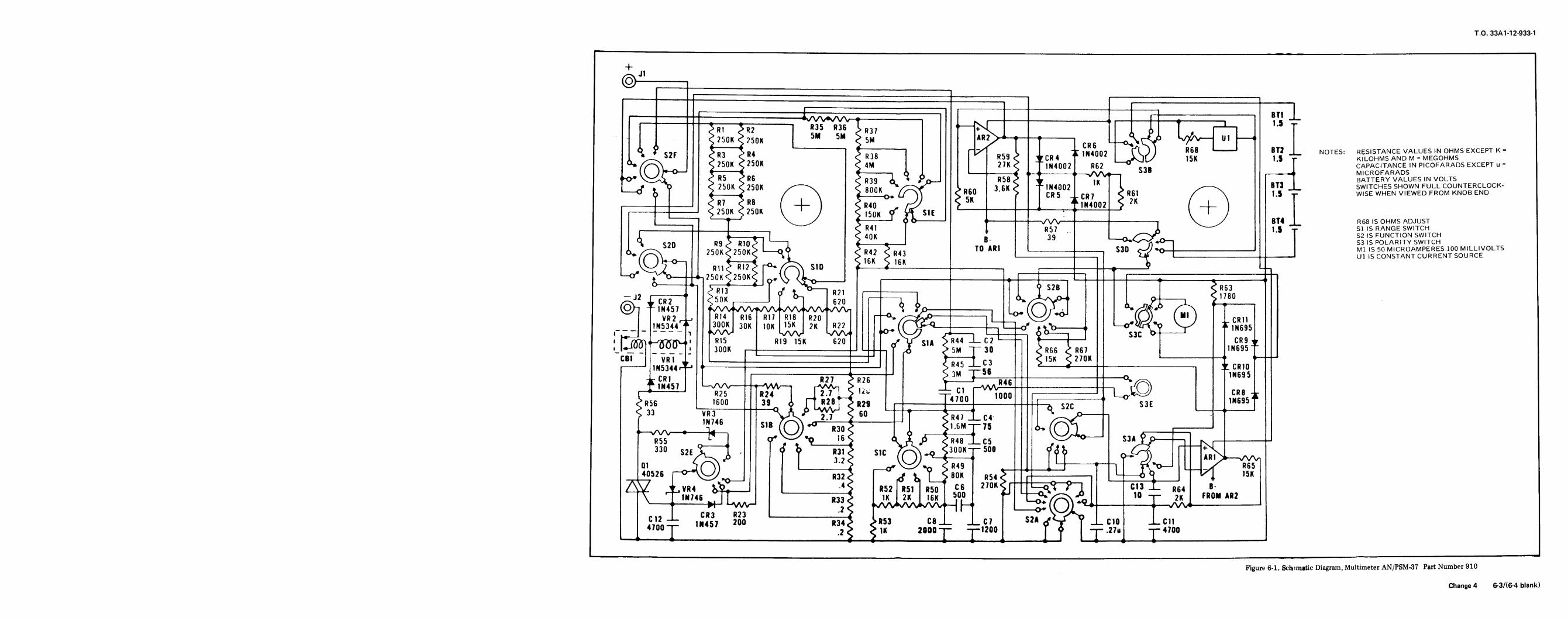
T.0.33A1-12-933-1
^@---,-----|I""""" . . -^/V\^/V\. ----. ,----F y ==, BT,1-r ^R1 ^2------| "5 R36 ,3, "’^T o _> I , PH1 ^ 250K > 250K
5M 5M Z 5M ^.X l CR6 --^^T "A^- "l --’\ OP "m ’’R4 "T^-----I r?^ I 1N4002 C^O ) R68 BT2 NOTES: RESISTANCE VALUES IN OHMS EXCEPT K=- " "3 "4 R38 R59 <> FCR4 1N4UU/ ..kJC/ 15K l.S T KILOHMSAND M MEGOHMS
* /y-\\ 250K 250K 4M 27K < "1N4002 R62 - ciD CAPACITANCE IN PICOFARADS EXCEPT u
\.\. Jr~~ ----^ ^------l Q ,, --- ----- i^-< --^V^.-- S",-----i MICROFARADS
O^ Y^^. R5 R6 R39 A * y^_ R58^ IK BATTERY VALUES IN VOLTS
__J T? 250K 250K /---\ nnnK ’/^^T ocn 3 6K ^ -1N4002 S .--\ BT3 SWITCHES SHOWN FULL COUNTERCLOCK-’--0 ^ 2_____^ / \ ) u
r^, U \\ S"60 ’u"^ rR5 rm < R61 /r \ 1.$ T WISE WHEN VIEWED FROM KNOB END
,_____-___I ^ Z RB f + ) ^0^ r^ V^-- -.----^1N<002 ^ 2K f -4- ^I--------J ^ 250K ^ 250K ^ ^ 7 ^50’< Y A S1E ^---- -----^---^ \ )\___y 9 6------’ ---------y\/\-- ---------------I \ / BT4 R68 IS OHMS ADJUSTR41 R57 A 1 T Sl IS RANGE SWITCH
1 4QK D 39 /""^ S2 IS FUNCTION SWITCH
^ t?n R9 ^ RIO^ --I , B- --^ -^d*0""! S3 is POLARITY SWITCH
<L/^"0 250Ki250K^ L ^ ^?^ To AR1 1---------=-j
S3D ^^+ ’- _____I U; IS5 CON’STANT^U^N’SO’U^0^(Q^ } ^^ir-^^ Y ^6K---- --^-^ LL^ ^^>-- -^250K ^250K^ ^ <ko ,------------------- t j LL-_-L "-|
-^ ^13-i ^ ^-r^ ^ S2B s ""<, "U ri R21 l---------l i <’- nQn
^ ^CRT"^ ^OK ^--l ^ 620 r-?> ^ ^/^V1 o ^r"^ ^80
(Q;-l -1N457 s/V\/ >yw^AA/ ^V^- sAA^ ^Wi ^ ?j0---------, (( ) f1.! -/^^ /.,~^VR2 "14 R16 R17 R18 R20 [~ ^/^^-------I ^^ (DJ ( 111 ) CR111N5344^ 300K 30K 10K ’5K 2K P22 (r^?^--------i M-^ t ^----< Lo-y^o \^ ;E-^695
r. -I -, ^A^j l^VV1 ^A/ 0^ \^9 ^ L3---, O^--T S3C 0----T/70^, ^x70^ R15 R19 15K 620 /^ V SI* > R44 -L- C2 ’---1 t------’ CR9 ^,_\^00 _00_0^. 3oon --------------J L- <? J S 5M -1- 30 <> R66 <> R67 1N695-
CB1 VRl 1 ) .,, p, < 15K ^ 270K ’--------- --l
I---’ 1N5344^yJ --------------------------’ > R45 =^LJ d----------------------| ^ CRIOi_____________________i________ S ll|j| 30 INKQ^
^ CRI R27 ?R26 ^3M ^---R4c ----------------^ ^, 11<695
1N457 ^-NA/V---r-A\^-t r^^n ? T p, i-VNAr-’1-------------i rD)
^" "- ^ 1 lllrl " , T4700 --ol>o-^=jje--J^---c< 33 ^TBT---- ----0, A y "AV^ ^ -n ’---T----^---’ S. ___ l---^----1? "<3 V-1*^* 2 7 S 6" T ?R47 r4 ^-^^---"Iy_-_\ \. ww^ ^ ^\M
^ SIB ^O) ^ R30 <------ 1 ^1 6M--75 <L (TY} .--.---IR^ ^"1 ! f r- ^---^ \J, ^ ^R48 __C5 V-:::>AO--1 "^JL^-I--K^------ -1330 ^^^ f t "i? slc (o)-^30^" 500 fft_ <^;? r’ S-^,01 _-jr y) ? _^^\ < R49 j H----r--l f<’0-l --^< "65
40526 -^^/ R^ ^ ^ _S 80K ^^ L--6 9 ^\ 15K
Z^ ^VR4 A__ ________^ R52 R5l R50 C6 270K^J- -T^q?""^"! "3 _L RM B-"< " 1N746 ^ T R33^ 1K 2K 16K 500 "J L^/^\^ ^ -T 2K "ON AR2N---’-----M-I LWV-1 1’’’J > ^AA^AA^W^ ^- 0^ (01^^-------’--^v^----------
FBI R?3 ? ^^ ^ "^^s^cl2 =L 1N457 200 ---------"4? >W C8__ C7 S2A ^V ^ +/- C10 +/- C114700-T- """ ^
S ^ ,K 2000- --1200 [ 0 -r-.27u -r- 4700
Figure 6-1. Sch’matic Diagram, Multimeter AN/PSM-37 Part Number 910
Change 4 6-3/(6 4 blank)


T0.33A1 -12-933-1
-------____-_______________-----_...-___________________________________________,________________________________.__-___________-___________----- ""i
+/-^ J1
@--------I_________________________------< =~ -,=]----------------1 BT1
,__~~~"" --^^AA^^A^T-----------I ,v 1------------------’ I-----H---T--------l 5 -r""^Rl ^R2------ "35 "6 R37 ’--H. < P i L/ f
250K ?50K5N 5M 5M AR2>L^---.-----, L^^ {^- "’ ---6 V i---< ’-------I <------l r^l I -: iM4nn9 C\J R68 ^--- BT2 NOTES: RESISTANCE VALUES IN OHMS EXCEPT K
* S2F R3 R4 R38 l’ R59 < rCR4 "<<ulJ’ _kjr/ )5K 1.5 r KILOHMS ANO M MEGOHMS
^ /^\ 250K 250K 4M 27K Z "1N4002 R62 "c-,. CAPACITANCE IN PICOFARADS EXCEPT u
)}-o-1 -----4 i______. JL I________^ ,_ __./\/\,a__. SJB i-----’ MICROFARADS’^W^ S R5 R6 ^ oTd 1 ^ P R58 ^ iK BATTERY VALUES IN VOLTS
^^ ^0 250K 7?f1K ^--\39 Q- ^-<^’ - KK ^ ^^N4002 "< l ^--^
BT3 SWITCHES SHOWN FULL COUNTERCLOCK-1--^ ^ T S Ju S 25^ ^ ^ BOOK /^C <> R60 ^" S rB< < R61 ^ \ 1.5 T" WISE WHEN VIEWED FROM KNOB END
T \----< / \ ----0 > t;ll’l LK7 ^ IK / \,-------___I < R7 ? R8 ( 1_ \ ^ R40 r^ ^ 5K ^ 1H4002 <; 2K -l-
^----------J ?50K 250K \^ 0^ ^ S1E ^----------^ \ 7
’-----| ’-----’ \, ./ ? ^u^--J f^_____) ^---------^^--\ / gy4 R68 IS OHMS ADJUST
L-------1 R4) ni,7 1 5 T Sl IS RANGE SWITCH|------------------------| * "J
/^~^r S2 IS FUNCTION SWITCH6 oo \ nin ^ l---i 2 B- --0<.<^-^^0-, S3 IS POLARITY SWITCH
L^20 25R0^25;OKt L^ ^2 ^J TO AR1 _L_____ S3D ^:^- _____-____ un^oNTTANT^^^^^({J^ ^,^T^ r-. /^ sio ^Li^i^^.._____, ----.---5 L
^ ^0--- ^250K^250K^ \^ <ko_--- ----------------------r- [ ~L:---------T--------5--------
----^ c^RT’--- T rf ^ ^>=\ ^ S2B < R63
@-I ’^N457 ’\AA/sAA^AA/^V^^AA^^AAn ^ ^0---------, (0 r3 /^ ^M^^ ’^
VR2 ^-.R’4 R)6 R17 R18 R20 r"^ /^^?0---------^ ^^ .-IV^ l V -r CR11
^5344^ 300K 30K 10K ’^ 2K R2? ff \>-Q^-______-_ __</ ’b____u l-<^<<’r\^? v^ ^ 1N695,- i ^/W1 ^AA^ [W^ .-0-’ \V^7 ^Wl^^iyg^^g. -<J
^ ^-~. S3C b----I 1L ^n’^CT^11 R15 R’9 15K 620 ^ V SIAl ^ R45-LC^8I|--, ^----(^-- IN^?^^|<JUU _UUU 3QQH ----------------J [___ < ^ ^ <^ g^ ^ ^ ^ ^ p^ 1N695
CBl VRI ",; I---- Z=+/-’ ^ r^ cis i S 1^ S 27^_______-ZZZ,--^r rRin|---’ lN5344r1-’ ---------------------------I l ^"69 ^^ ! -----^--------------------| -r cR10
,-----------------ii_____-I W ) 2VM s^ ^ 1N695-l^ CRl R27 ^ R26 i y---11 "ism :::;s:;;: ssssmmmmmws^m^wr "’4’17 ^^--^R^n rT^t S ^O g S R70 -_C16 ___________) g CR8 -,"3 K/4 _1 i__^ S:^ >9Vi\/l -I- 82 i:::< IMCQ’i
(>R5g 1600 39 6 H28 ’> DIO _____^. ^ aig^S ^ ^ S Ss s^s inoaa
< 33 LVR3-----"~^A ^^ ^ 60 "- T i ^ R47 ^_C17 | ’>^^---1N 7 4 6 c D //-\\ <T-----^------- as; -> SS: //^~\^\-1^ (( )) R30 < 1 i S1-"’" - i ""- (l ) ____-----
^^ " ? (yr Y^/ ’p 16 ^ <t A rS""^^^^ Y^^O---1 S3A 9 p-^- f^s, 1--------330 S2E X~J, f ^> R3^ SIC /^^ ^OOK== 500 </^ 6^ ---^^^o1 1( ^ f -^^/^ < R49 i ^---r""! fV^ -X p65
40526 r^y^,, -----R32^ r^^ ^ U 8^ "54 r r=--------| ^--^\ ^ 15K
^ ^VM ^---- |---------^ ^ .5. R50 ^ ^fnt^CT ^T ^K4 ^ ^\ ln/46 DTI /> )K 2K )6K L-n- /^~\\ ...//ft
\--------^J Ly^J ’<33 < ,sAA^AA^W-| [-^ a^ COl --------’--^^-----------^p., CR3 R23 _____________^ ^g^ssi^gggg <- <Z f- X)2
1N457 200 R34Z <>53 i C9 --sl C7 S2A ^ ^T T -L 010 -L- C114700-- "’4:l/
"^ S S K( |jtMSL:-i --1200 [ y -r-.27u -l- 4700--"------<’-------------------------------^-i---^----,-^gaa^saasss^ .:..?.--^^_____^--------^--J )--^----^-----^---------_-^---------
Figure 6-2. Schematic Diagram, Multimeter AN/PSM-37 Part Number 960
Change 5 6-51(6-6 Blank)