Embed Size (px)
Citation preview

MULTIFUNCTION METER FOR
ELECTRICAL PARAMETERS MONITORING
MULTIFUNCTION METERS NEMO

2
all informationall documentation
www.imeitaly.com
WEBSITE

3
IN THE IME WEBSITE YOU CAN:→
see a complete product range
download, Technical Documentation, Technical Guide, management Software, Firmware, catalogue
discover the news about product and events
find all technical notesabout products (NTcode)
9
MultifunctionKIT Multifunction and CT for low voltage
n Technical features
n Wiring diagrams n Wiring diagrams
Cat. Nos. KIT Nemo D4-B + 3 CT
Input (A) /CT (A) Input (V) Auxiliary supply Output
K1NEMOD4B040 5 / 3CT 40/5 80…480 230-240 Vac -
K1NEMOD4B050 5/ 3CT 50/5 80…480 230-240 Vac -
K1NEMOD4B060 5/ 3CT 60/5 80…480 230-240 Vac -
K1NEMOD4B100 5/ 3CT 100/5 80…480 230-240 Vac -
K1NEMOD4B150 5/ 3CT 150/5 80…480 230-240 Vac -
K1NEMOD4B200 5/ 3CT 200/5 80…480 230-240 Vac -
K1NEMOD4B250 5/ 3CT 250/5 80…480 230-240 Vac -
Three-phase network 3-wire (ARON L1-L3) Three-phase network 4-wire
Three-phase network 3-wire (ARON L1-L2)
* for switchboard thermal calculation
Connection via dedicated CT for single and three-phase network, 3 or 4-wires.
Functions• Phase voltage/current• Linked voltage• Phase active/reactive power• Active, reactive, apparent power• Neutral current• Frequency• Working hours and minutes• Power demand and power max. demand• Phase current demand and phase current max. demand
TECHNICAL NOTES NT860INPUTThree-phase voltage (V) 80...480 (phase-phase)Current rating 5AContinuous overload 1,2InIstantaneous overload 20Imax/0,5sReference frequency 50HzFrequency tolerance 47…63HzType of measurement true RMSHarmonic content up to the 21th harmonicVoltage rated burden (VA) ≤1 (each phase)Current rated burden (VA) ≤0,5 (each phase)AUXILIARY SUPPLYRated value Uaux 230 and 240 Tolerance 0,85…1,1 UauxReference frequency 50HzFrequency tolerance 47…63HzRated burden ≤ 5VA – 2,5WACCURACYActive energy kWh EN/IEC 62053-21 cl. 0,5DISPLAYType of display LCD backlightedDigit height 6mmEnergy resolution depending on the CT ratioMECHANICAL FEATURESHousing 4 modules DIN 43880 (35mm)Housing material self-extinguishing policarbonateProtection degree IP20 terminals/ IP54 front frameConnections type screw terminals
Rigid cable output - max 4mm2
input - max 4mm2
Flexible cable output - max 2,5mm2
input - max 2,5mm2
ENVIRONMENTAL CONDITIONSNominal temperature range -5…55°CLimit range for storage and transport -25…70°CSuitable for tropical climates yes Max.power dissipation* ≤6,8W
X
XX
L1
L2
L3
S1
P1
S1
P1
2 5 8 11 1 3 4 6 7 9 20 21
X
XX
S1
P1 S1
P1
L1
L2
L3
2 5 8 11 1 3 4 6 7 9 20 21
X
XX
S1
P1 S1
P1 S1
P1
L1
L2
L3
NX X X
2 5 8 11 1 3 4 6 7 9 20 21
VOLTAGE CURRENT
AUX.SUPPLY
I N P U TVOLTAGE CURRENT
AUX.SUPPLY
I N P U T
VOLTAGE CURRENT
AUX.SUPPLY
I N P U T
X
XX
L1
L2
L3
S1
P1
S1
P1
2 5 8 11 1 3 4 6 7 9 20 21
X
XX
S1
P1 S1
P1
L1
L2
L3
2 5 8 11 1 3 4 6 7 9 20 21
X
XX
S1
P1 S1
P1 S1
P1
L1
L2
L3
NX X X
2 5 8 11 1 3 4 6 7 9 20 21
VOLTAGE CURRENT
AUX.SUPPLY
I N P U TVOLTAGE CURRENT
AUX.SUPPLY
I N P U T
VOLTAGE CURRENT
AUX.SUPPLY
I N P U T
X
XX
L1
L2
L3
S1
P1
S1
P1
2 5 8 11 1 3 4 6 7 9 20 21
X
XX
S1
P1 S1
P1
L1
L2
L3
2 5 8 11 1 3 4 6 7 9 20 21
X
XX
S1
P1 S1
P1 S1
P1
L1
L2
L3
NX X X
2 5 8 11 1 3 4 6 7 9 20 21
VOLTAGE CURRENT
AUX.SUPPLY
I N P U TVOLTAGE CURRENT
AUX.SUPPLY
I N P U T
VOLTAGE CURRENT
AUX.SUPPLY
I N P U T
4
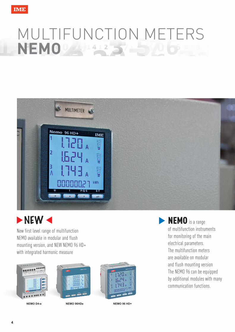
MULTIFUNCTION METERS NEMO
NEMO is a range of multifunction instruments for monitoring of the main electrical parameters.The multifunction meters are available on modular and flush mounting versionThe NEMO 96 can be equipped by additional modules with many communication functions.
New first level range of multifunctionNEMO available in modular and flushmounting version, and NEW NEMO 96 HD+ with integrated harmonic measure
NEMO D4-e NEMO 96HDe NEMO 96 HD+

5
CountingActive and reactive energy.Run hours.
MeasuresSimultaneously all the parameters of the electrical network, such as voltages, currents, frequency, power factor, active, reactive and apparent power.
AnalysisThe quality of the supply by computing the single harmonics of current and voltage.
WarningAbnormal events by alarm relays activation, in field programmed.
ComplyWith the technical characteristicsof the installation thanks to its in field programming mode of the electrical network (single phase or three phase 3/4 wires) and of CT’s and VT’s ratios.
TransmitTo a remote controller the dataand the configuration of thedevice, through RS232 or RS485or by pulse outputs. It iscompatible with ModBus RTU,Profibus, M-Bus, LonWorks,BACnet and Ethernet networks.
ComputingAverage and max current.Average and max power.
DisplayAll the electrical parameterson a backlit LED screen,easily accessed by keyboard.

6
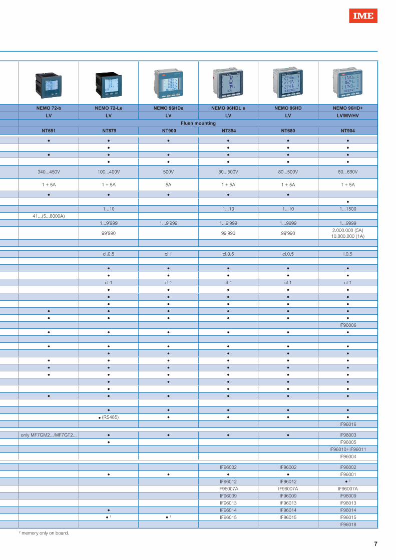
Multifunction metersSelection table
Model NEMO D4-b NEMO D4-e NEMO D4-Le NEMO D4-L+ NEMO D4-Dc NEMO 72-b NEMO 72-Le NEMO 96HDe NEMO 96HDL e NEMO 96HD NEMO 96HD+
Network LV LV LV LV/MV DC LV LV LV LV LV LV/MV/HV
Installation DIN rail Flush mounting
Technical notes NT588 NT901 NT864 NT695 NT753 NT651 NT879 NT900 NT854 NT680 NT904
INP
UT
Connection
1Ph ● ● ● ● ● ● ● ● ● ●
3Ph balanced load ● ● ● ● ● ● ●
3Ph unbalanced load ● ● ● ● ● ● ● ● ● ●
Phase sequence correction, diagnostic ● ● ● ● ● ● ●
Rated valueVoltage 80...480V 80...500V 80...500V 80...480V
10...300V50... 1500V
340...450V 100...400V 500V 80...500V 80...500V 80...690V
Current 1 - 5A 5A 1 + 5A 1 + 5A10A
shunt 60-100-150mV1 + 5A 1 + 5A 5A 1 + 5A 1 + 5A 1 + 5A
Input currentDedicated CT ● ● ● ● ● ● ● ●
Insulated ● ●
Programmable Ratio
Insulated 1...10 1...10 1...400 1...10 1...10 1...10 1...1500
CTRanges 41...(5...8000A) 41...(5...8000A)
Isn 1...9’999 1...9’999 1...9’999 1...9’999 1...9’999 1...9’999 1...9999 1...9999
Max. kVT x kCT 99’990 99’990100.000(5A)400.000(1A)
99’990 99’990 99’9902.000.000 (5A)
10.000.000 (1A)
Shunt 1...9999
DIS
PL
AY
Active energy
Accuracy EN/IEC 61557-12 cl.1 cl.0,5 cl.1 cl.0,5 cl.1 cl.0,5 cl.0,5 l.0,5
Energy dc accuracy cl.1
Positive, total and partial ● ● ● ● ● ● ● ● ●
Negative, total ● ● ● ● ● ● ● ●
Reactive energy
Accuracy EN/IEC 61557-12 cl.1 cl.1 cl.2 cl.1 cl.1 cl.1 cl.1 cl.1
Positive, total ● ● ● ● ● ● ● ●
Positive, partial ● ● ● ● ● ● ●
Negative, totale ● ● ● ● ● ● ●
Voltage Phase and linked ● ● ● ● ● ● ● ● ● ●
Current
Phase and neutral ● ● ● ● ● ● ● ● ●
Neutral (measured) ● IF96006
Phase demand and max. Demand ● ● ● ● ● ● ● ● ● ●
Positive and negative Ah ●
Power factorThreee-phase ● ● ● ● ● ● ● ● ● ●
Phase ● ● ● ● ● ● ●
Power
Active,reactive, apparent ● ● ● ● ● ● ● ● ● ●
Demand and max. Demand ● ● ● ● ● ● ● ● ● ● ●
Phase active and reactive ● ● ● ● ● ● ● ● ● ●
Harmonic distortion
Thd current / voltage ● ● ● ● ● ● ● ●
Analysis ● ● ● ● ●
Frequency ● ● ● ● ● ● ● ● ● ●
D.C.1 Measure ●
Run hour meter ● ● ● ● ● ● ● ● ● ●
Wrong phase sequence ● ● ● ● (RS485) ● ● ● ●
Temperature IF96016
OU
TP
UT Pulse ● ● ● ● only MF7GM2.../MF7GT2... ● ● ● ● IF96003
Alarm relays ● ● IF96005
Alarm relays + digital inputs ● IF96010+IF96011
Analogue IF96004
CO
MM
UN
ICA
TIO
N
RS232 IF96002 IF96002 IF96002
RS485 Modbus RTU ● ● ● ● ● ● ● ● IF96001
RS485 + Memory IF96012 IF96012 ● 2
Profibus IF96007A IF96007A IF96007A
Lonworks IF96009 IF96009 IF96009
M-bus IF96013 IF96013 IF96013
Bacnet ● ● ● IF96014 IF96014 IF96014
Ethernet ● 1 ●
1 ● 1 ●
1 ● 1 ●
1 IF96015 IF96015 IF96015
868Mhz radio trasmission IF96018 1 RS485 version + external interface (IF2E or IF4E)
7
Model NEMO D4-b NEMO D4-e NEMO D4-Le NEMO D4-L+ NEMO D4-Dc NEMO 72-b NEMO 72-Le NEMO 96HDe NEMO 96HDL e NEMO 96HD NEMO 96HD+
Network LV LV LV LV/MV DC LV LV LV LV LV LV/MV/HV
Installation DIN rail Flush mounting
Technical notes NT588 NT901 NT864 NT695 NT753 NT651 NT879 NT900 NT854 NT680 NT904
INP
UT
Connection
1Ph ● ● ● ● ● ● ● ● ● ●
3Ph balanced load ● ● ● ● ● ● ●
3Ph unbalanced load ● ● ● ● ● ● ● ● ● ●
Phase sequence correction, diagnostic ● ● ● ● ● ● ●
Rated valueVoltage 80...480V 80...500V 80...500V 80...480V
10...300V50... 1500V
340...450V 100...400V 500V 80...500V 80...500V 80...690V
Current 1 - 5A 5A 1 + 5A 1 + 5A10A
shunt 60-100-150mV1 + 5A 1 + 5A 5A 1 + 5A 1 + 5A 1 + 5A
Input currentDedicated CT ● ● ● ● ● ● ● ●
Insulated ● ●
Programmable Ratio
Insulated 1...10 1...10 1...400 1...10 1...10 1...10 1...1500
CTRanges 41...(5...8000A) 41...(5...8000A)
Isn 1...9’999 1...9’999 1...9’999 1...9’999 1...9’999 1...9’999 1...9999 1...9999
Max. kVT x kCT 99’990 99’990100.000(5A)400.000(1A)
99’990 99’990 99’9902.000.000 (5A)
10.000.000 (1A)
Shunt 1...9999
DIS
PL
AY
Active energy
Accuracy EN/IEC 61557-12 cl.1 cl.0,5 cl.1 cl.0,5 cl.1 cl.0,5 cl.0,5 l.0,5
Energy dc accuracy cl.1
Positive, total and partial ● ● ● ● ● ● ● ● ●
Negative, total ● ● ● ● ● ● ● ●
Reactive energy
Accuracy EN/IEC 61557-12 cl.1 cl.1 cl.2 cl.1 cl.1 cl.1 cl.1 cl.1
Positive, total ● ● ● ● ● ● ● ●
Positive, partial ● ● ● ● ● ● ●
Negative, totale ● ● ● ● ● ● ●
Voltage Phase and linked ● ● ● ● ● ● ● ● ● ●
Current
Phase and neutral ● ● ● ● ● ● ● ● ●
Neutral (measured) ● IF96006
Phase demand and max. Demand ● ● ● ● ● ● ● ● ● ●
Positive and negative Ah ●
Power factorThreee-phase ● ● ● ● ● ● ● ● ● ●
Phase ● ● ● ● ● ● ●
Power
Active,reactive, apparent ● ● ● ● ● ● ● ● ● ●
Demand and max. Demand ● ● ● ● ● ● ● ● ● ● ●
Phase active and reactive ● ● ● ● ● ● ● ● ● ●
Harmonic distortion
Thd current / voltage ● ● ● ● ● ● ● ●
Analysis ● ● ● ● ●
Frequency ● ● ● ● ● ● ● ● ● ●
D.C.1 Measure ●
Run hour meter ● ● ● ● ● ● ● ● ● ●
Wrong phase sequence ● ● ● ● (RS485) ● ● ● ●
Temperature IF96016
OU
TP
UT Pulse ● ● ● ● only MF7GM2.../MF7GT2... ● ● ● ● IF96003
Alarm relays ● ● IF96005
Alarm relays + digital inputs ● IF96010+IF96011
Analogue IF96004
CO
MM
UN
ICA
TIO
N
RS232 IF96002 IF96002 IF96002
RS485 Modbus RTU ● ● ● ● ● ● ● ● IF96001
RS485 + Memory IF96012 IF96012 ● 2
Profibus IF96007A IF96007A IF96007A
Lonworks IF96009 IF96009 IF96009
M-bus IF96013 IF96013 IF96013
Bacnet ● ● ● IF96014 IF96014 IF96014
Ethernet ● 1 ●
1 ● 1 ●
1 ● 1 ●
1 IF96015 IF96015 IF96015
868Mhz radio trasmission IF96018
2 memory only on board.

8
Multifunction metersMultifunction for low voltage
n Technical features
n Wiring diagrams n Wiring diagrams
Cat. Nos. Nemo D4-B
Input (A) Input* (V) Auxiliary supply Output
MF6GT00073 5 80…480 115 Vac -
MF6GT00076 5 80…480 230 Vac -
MF6GT00079 5 80…480 400 Vac -
MF6GT00063 1 80…480 115 Vac -
MF6GT00066 1 80…480 230 Vac -
MF6GT00069 1 80…480 400 Vac -
Connection via CT for single and three-phase network, 3 or 4-wires.
Functions• Phase and linked voltage• Neutral and phase current• Current demand and current max. demand• Power demand and power max. demand• Power factor• Frequency• Run hour meter, count start with voltage present
* Three-phase input 80…480V, Single -phase input 50…350V
Three-phase network 3-wire (ARON L1-L3)
Three-phase network 3-wire (ARON L1-L2)
TECHNICAL NOTES NT588INPUTThree-phase voltage (V) 80...480 (phase-phase)Single-phase voltage (V) 50...350Current rating 1A - 5A
External CT ratio
5/10/15/20/25/30/40/50/60/70/75/80/100/120/125/150/160/200/250/300/
400/500/600/700/750/800/1000/1200/1250/1500/1600/2000/2500/3000/
3200/4000/5000/6000/7000/7500/8000AContinuous overload 1,2InIstantaneous overload 20Imax/0,5sReference frequency 50HzFrequency tolerance 47…63HzType of measurement true RMSHarmonic content up to the 16th harmonicVoltage rated burden (VA) ≤1 (each phase)Current rated burden (VA) ≤0,5 (each phase)AUXILIARY SUPPLYRated value Uaux 115 – 230 - 400VTolerance 0,85…1,1 UauxReference frequency 50HzFrequency tolerance 47…63HzRated burden ≤ 5VA – 2,5WDISPLAYType of display LCD backlightedDigit height 6mmMECHANICAL FEATURESHousing 4 modules DIN 43880 (35mm)Housing material self-extinguishing policarbonateProtection degree IP20 terminals/ IP54 front frameConnections type screw terminals
Rigid cable output - max 4mm2
input - max 4mm2
Flexible cable output - max 2,5mm2
input - max 2,5mm2
ENVIRONMENTAL CONDITIONSNominal temperature range -5…55°CLimit range for storage and transport -25…70°CSuitable for tropical climates yes Max.power dissipation* ≤6,8W
* for switchboard thermal calculation
X
XX
S1
P1 S1
P1 S1
P1
L1
L2
L3
NX X X
2 5 8 11 1 3 4 6 7 9
VOLTAGE CURRENT
20
AUX.SUPPLY
21
I N P U T
2 5 8 11 1 3
X
S1
P1
4 6 7 9
L
N
20 21
X
XX
L1
L2
L3
S1
P1
S1
P1
2 5 8 11 1 3 4 6 7 9 20 21
X
XX
S1
P1 S1
P1
L1
L2
L3
2 5 8 11 1 3 4 6 7 9 20 21
VOLTAGE CURRENT
AUX.SUPPLY
I N P U T
VOLTAGE CURRENT
AUX.SUPPLY
I N P U T
VOLTAGE CURRENT
AUX.SUPPLY
I N P U T
Single-phase network
X
XX
S1
P1 S1
P1 S1
P1
L1
L2
L3
NX X X
2 5 8 11 1 3 4 6 7 9
VOLTAGE CURRENT
20
AUX.SUPPLY
21
I N P U T
2 5 8 11 1 3
X
S1
P1
4 6 7 9
L
N
20 21
X
XX
L1
L2
L3
S1
P1
S1
P1
2 5 8 11 1 3 4 6 7 9 20 21
X
XX
S1
P1 S1
P1
L1
L2
L3
2 5 8 11 1 3 4 6 7 9 20 21
VOLTAGE CURRENT
AUX.SUPPLY
I N P U T
VOLTAGE CURRENT
AUX.SUPPLY
I N P U T
VOLTAGE CURRENT
AUX.SUPPLY
I N P U T
Three-phase network 4-wire
X
XX
S1
P1 S1
P1 S1
P1
L1
L2
L3
NX X X
2 5 8 11 1 3 4 6 7 9
VOLTAGE CURRENT
20
AUX.SUPPLY
21
I N P U T
2 5 8 11 1 3
X
S1
P1
4 6 7 9
L
N
20 21
X
XX
L1
L2
L3
S1
P1
S1
P1
2 5 8 11 1 3 4 6 7 9 20 21
X
XX
S1
P1 S1
P1
L1
L2
L3
2 5 8 11 1 3 4 6 7 9 20 21
VOLTAGE CURRENT
AUX.SUPPLY
I N P U T
VOLTAGE CURRENT
AUX.SUPPLY
I N P U T
VOLTAGE CURRENT
AUX.SUPPLY
I N P U T
X
XX
S1
P1 S1
P1 S1
P1
L1
L2
L3
NX X X
2 5 8 11 1 3 4 6 7 9
VOLTAGE CURRENT
20
AUX.SUPPLY
21
I N P U T
2 5 8 11 1 3
X
S1
P1
4 6 7 9
L
N
20 21
X
XX
L1
L2
L3
S1
P1
S1
P1
2 5 8 11 1 3 4 6 7 9 20 21
X
XX
S1
P1 S1
P1
L1
L2
L3
2 5 8 11 1 3 4 6 7 9 20 21
VOLTAGE CURRENT
AUX.SUPPLY
I N P U T
VOLTAGE CURRENT
AUX.SUPPLY
I N P U T
VOLTAGE CURRENT
AUX.SUPPLY
I N P U T

9
Multifunction metersKIT Multifunction and CT for low voltage
n Technical features
n Wiring diagrams n Wiring diagrams
Cat. Nos. KIT Nemo D4-B + 3 CT (TAIBB model)
Input (A) /CT (A) Input (V) Auxiliary supply Output
K1NEMOD4B040 5 / 3CT 40/5 80…480 230 Vac -
K1NEMOD4B050 5/ 3CT 50/5 80…480 230 Vac -
K1NEMOD4B060 5/ 3CT 60/5 80…480 230 Vac -
K1NEMOD4B100 5/ 3CT 100/5 80…480 230 Vac -
K1NEMOD4B150 5/ 3CT 150/5 80…480 230 Vac -
K1NEMOD4B200 5/ 3CT 200/5 80…480 230 Vac -
K1NEMOD4B250 5/ 3CT 250/5 80…480 230 Vac -
Three-phase network 3-wire (ARON L1-L3) Three-phase network 4-wire
Three-phase network 3-wire (ARON L1-L2)
* for switchboard thermal calculation
Connection via dedicated CT for single and three-phase network, 3 or 4-wires.
Functions• Phase and linked voltage• Neutral and phase current• Current demand and current max. demand• Power demand and power max. demand• Power factor• Frequency• Run hour meter, count start with voltage present
TECHNICAL NOTES NT860INPUTThree-phase voltage (V) 80...480 (phase-phase)Current rating 5AContinuous overload 1,2InIstantaneous overload 20Imax/0,5sReference frequency 50HzFrequency tolerance 47…63HzType of measurement true RMSHarmonic content up to the 16th harmonicVoltage rated burden (VA) ≤1 (each phase)Current rated burden (VA) ≤0,5 (each phase)AUXILIARY SUPPLYRated value Uaux 230Tolerance 0,85…1,1 UauxReference frequency 50HzFrequency tolerance 47…63HzRated burden ≤ 5VA – 2,5WACCURACYActive energy kWh EN/IEC 62053-21 cl. 0,5DISPLAYType of display LCD backlightedDigit height 6mmMECHANICAL FEATURESHousing 4 modules DIN 43880 (35mm)Housing material self-extinguishing policarbonateProtection degree IP20 terminals/ IP54 front frameConnections type screw terminals
Rigid cable output - max 4mm2
input - max 4mm2
Flexible cable output - max 2,5mm2
input - max 2,5mm2
ENVIRONMENTAL CONDITIONSNominal temperature range -5…55°CLimit range for storage and transport -25…70°CSuitable for tropical climates yes Max.power dissipation* ≤6,8W
X
XX
L1
L2
L3
S1
P1
S1
P1
2 5 8 11 1 3 4 6 7 9 20 21
X
XX
S1
P1 S1
P1
L1
L2
L3
2 5 8 11 1 3 4 6 7 9 20 21
X
XX
S1
P1 S1
P1 S1
P1
L1
L2
L3
NX X X
2 5 8 11 1 3 4 6 7 9 20 21
VOLTAGE CURRENT
AUX.SUPPLY
I N P U TVOLTAGE CURRENT
AUX.SUPPLY
I N P U T
VOLTAGE CURRENT
AUX.SUPPLY
I N P U T
X
XX
L1
L2
L3
S1
P1
S1
P1
2 5 8 11 1 3 4 6 7 9 20 21
X
XX
S1
P1 S1
P1
L1
L2
L3
2 5 8 11 1 3 4 6 7 9 20 21
X
XX
S1
P1 S1
P1 S1
P1
L1
L2
L3
NX X X
2 5 8 11 1 3 4 6 7 9 20 21
VOLTAGE CURRENT
AUX.SUPPLY
I N P U TVOLTAGE CURRENT
AUX.SUPPLY
I N P U T
VOLTAGE CURRENT
AUX.SUPPLY
I N P U T
X
XX
L1
L2
L3
S1
P1
S1
P1
2 5 8 11 1 3 4 6 7 9 20 21
X
XX
S1
P1 S1
P1
L1
L2
L3
2 5 8 11 1 3 4 6 7 9 20 21
X
XX
S1
P1 S1
P1 S1
P1
L1
L2
L3
NX X X
2 5 8 11 1 3 4 6 7 9 20 21
VOLTAGE CURRENT
AUX.SUPPLY
I N P U TVOLTAGE CURRENT
AUX.SUPPLY
I N P U T
VOLTAGE CURRENT
AUX.SUPPLY
I N P U T

10
Multifunction metersMultifunction for low voltage
n Technical features
Cat. Nos. Nemo D4-e
Input (A) Input* (V) Auxiliary supply Output
MFD4E06 5 80…500 230Vac Pulse + RS485 ModBus RTU
Connection via CT for single and three-phase network, 3 or 4-wires.Phase sequence correction, diagnosticIt makes available active or reactive energy counting of the pulse output to integration of consumption supervision systems.For supervision systems, through the model with output RS485 communication ModbusRTU, you can transmitted on the network main electrical parameters in addition to the energy consumption.
Functions• Phase and linked voltage• Min. and max. phase voltage• THDV• Neutral and phase current• Current demand and current max. demand• Average current• THDI• Active, reactive phase power• Power demand and power max. demand• Positive and negative active and reactive energy• Power factor• Frequency• Run hour meter, count start with voltage or power present
* for switchboard thermal calculation** kCT MAXIMUN DISPLAY 1...9 999999,99kWh/kvarh 10...99 9999999,9kWh/kvarh 100...999 99999999kWh/kvarh 1000...9999 999999,99MWh/Mvarh
* Three-phase input 80…500V, Single -phase input 50…290V
TECHNICAL NOTES NT901INPUTThree-phase voltage (V) 80...500 (phase-phase)Single-phase voltage (V) 50...290VCurrent rating 5AExternal CT ratio max 50kA/5A Continuous overload 1,2InIstantaneous overload 20Imax/0,5sReference frequency 50Hz – 60Hz (automatic selection)
Frequency tolerance 45...65Hz (fn 50Hz) – 360...440Hz (fn 400Hz)
Type of measurement true RMSHarmonic content up to the 25th harmonicsVoltage rated burden (VA) ≤ 0,2VA (phase-neutral)Current rated burden (VA) ≤ 1VA (for phase)AUXILIARY SUPPLYRated value Uaux 230Vac Reference frequency 50HzFrequency tolerance 45…65Hz Rated burden ≤ 2,5VA (230Vac backlight 30%)ACCURACY
CONFORMITY ACCURACY WITH EN/IEC 61557-12
- Voltage: cl.0,5- Current: cl. 1
- Active energy: cl.1- Reactive energy cl.1
- Active power cl.1- Reactive power cl.1- Apparent power cl.1- Frequence ± 0,1 Hz
- THD cl.2DISPLAYType of display LCD backlightedDigit height 5/7mmEnergy resolution depending on the CT ratio **MECHANICAL FEATURESHousing 4 modules DIN 43880 (35mm)Housing material self-extinguishing policarbonateProtection degree IP20 terminals/ IP54 front frameConnections type screw terminals
Rigid cable output - max 4mm2
input - max 6mm2
Flexible cable output - max 2,5mm2
input - max 4mm2
ENVIRONMENTAL CONDITIONSNominal temperature range -5…55°CLimit range for storage and transport -25…70°CSuitable for tropical climates yes Max.power dissipation* ≤5W
n Output
ENERGY PULSES S0 EN/IEC 62053-31Type Optorelay with potential-freeContact range 27Vdc – 50mAAssignable energy Active or reactive energyPulse weight selectable 10Wh/Varh...10MWh/MVarhPulse duration selectable 50...300msRS485 COMMUNICATIONProtocol MODBUS RTUStandard RS485-3-wireBaud rate selectable 4800...19200 bit/s

11
Multifunction metersMultifunction for low voltage
2 5 8 111 3 64 7
S1
P1
a
A
b
BL
N LOADX
2 11
INPUT
VOLTAGE CURRENT
15 29 33 34 35
RS 485
OUTPUT
OUTPUT
0V
F
+ –
9
AUX.SUPPLY
+ –
20 21
X
XX
S1
P1 S1
P1 S1
P1
a
AL1
L2
L3
NX X X
LOAD
INPUT
VOLTAGE CURRENT
2 5 8 1 3 6 94 711
2 5 8 11
15 29 33 34 35
RS 485
OUTPUT
OUTPUT
0V
F
+ –
AUX.SUPPLY
+ –
20 21
X
XX
S1
P1
S1
P1
a
A
b
B
a
A
b
BL1
L2
L3
LOAD
2 5 8
INPUT
VOLTAGE CURRENT
2 5 8 1 3 94 711 15 29 33 34 35
RS 485
OUTPUT
OUTPUT
0V
F
+ –
6
AUX.SUPPLY
+ –
20 21
LOAD
X
XX
S1
P1 S1
P1 S1
P1
a
A
b
B
a
A
b
BL1
L2
L3
2 5 8
INPUT
VOLTAGE CURRENT
2 5 8 1 3 6 94 711 15 29 33 34 35
RS 485
OUTPUT
OUTPUT
0V
F
+ –
AUX.SUPPLY
+ –
20 21
n Wiring diagramsSingle phase network
3-phase network, 3 wire (ARON L1-L3)
3-phase network, 3 wire
3-phase network, 4 wire

12
Multifunction metersMultifunction for low voltage
n Technical features
Connection via CT for single and three-phase network, 3 or 4-wires.Phase sequence correction, diagnosticIt makes available active or reactive energy counting of the pulse output to integration of consumption supervision systems.For supervision systems, through the model with output RS485 communication ModbusRTU, you can transmitted on the network main electrical parameters in addition to the energy consumption.
Functions• Phase and linked voltage• Min. and max. phase voltage• THDV• Voltage Harmonic analysis• Voltage crest factor• Phase angle between voltage• Neutral and phase current• Current demand and current max. demand• Average current• THDI• Current Harmonic analysis• Current crest factor• Phase angle between current• Active, reactive phase power• Power demand and power max. demand• Positive and negative active and reactive energy• Power factor• Phase angle between current and voltage• Frequency• Run hour meter, count start with voltage or power present
Cat. Nos. Nemo D4-Le
Input (A) Input* (V) Auxiliary supply Output
MFD4411 1 + 5 80…500 80...265Vac100...300Vdc
Pulse or alarm
MFD4421 1 + 5 80…500 80...265Vac100...300Vdc
Pulse or alarm + RS485 ModBus RTU/TCP
MFD44B1 1 + 5 80…500 80...265Vac100...300Vdc
Pulse or alarm + RS485 BACnet
MFD4412 1 + 5 80…500 20...60 Vdc Pulse or alarm
MFD4422 1 + 5 80…500 20...60 Vdc Pulse or alarm + RS485 ModBus RTU/TCP
MFD44B2 1 + 5 80…500 20...60 Vdc Pulse or alarm+ RS485 BACnet
* Three-phase input 80…500V, Single -phase input 50…290V
TECHNICAL NOTES NT864INPUTThree-phase voltage (V) 80...500 (phase-phase)Single-phase voltage (V) 50...290VCurrent rating 1A - 5AExternal CT ratio max 50kA/5A - max 10kA/1AExternal VT ratio primary voltage max 1200V Continuous overload 1,2InIstantaneous overload 20Imax/0,5sReference frequency 50Hz – 400Hz (automatic selection)Frequency tolerance 45...65Hz (fn 50Hz) – 360...440Hz (fn 400Hz)Type of measurement true RMSHarmonic content up to the 50th harmonics (45...65Hz)Voltage rated burden (VA) ≤ 0,2VA (phase-neutral)Current rated burden (VA) ≤ 1VA (for phase)AUXILIARY SUPPLYRated value Uaux 80...265Vac - 48VacReference frequency 50 or 400Hz (automatic selection)Frequency tolerance 45…65Hz (fn 50Hz) or 360...440Hz (fn 400Hz)Rated burden ≤ 2,5VA (230Vac backlight 30%)Rated value Uaux 100...300Vdc - 20...60VdcRated burden ≤ 2,5W (24Vdc backlight 30%)ACCURACY
CONFORMITY ACCURACY WITH EN/IEC 61557-12
- Voltage: cl.0,5- Current: cl. 0,5
- Active energy: cl.0,5- Reactive energy cl.0,5
- Active power cl.05- Reactive power cl.1- Apparent power cl.1- Frequence ± 0,1 Hz
- THD (up to 50th harmonic) Harmonics single cl.1
DISPLAYType of display LCD backlightedDigit height 5/7mmEnergy resolution depending on the CT/VT ratio**MECHANICAL FEATURESHousing 4 modules DIN 43880 (35mm)Housing material self-extinguishing policarbonateProtection degree IP20 terminals/ IP54 front frameConnections type screw terminals
Rigid cable output - max 4mm2
input - max 6mm2
Flexible cable output - max 2,5mm2
input - max 4mm2
ENVIRONMENTAL CONDITIONSNominal temperature range -5…55°CLimit range for storage and transport -25…70°C
Suitable for tropical climates yes Max.power dissipation* ≤5W
* for switchboard thermal calculation** kCT*kVT MAXIMUN DISPLAY 1...9 999999,99kWh/kvarh 10...99 9999999,9kWh/kvarh 100...999 99999999kWh/kvarh 1000...9999 999999,99MWh/Mvarh 10000...99999 9999999,9MWh/Mvarh

13
Multifunction metersMultifunction for low voltage
2 5 8 111 3 6 94 7
S1
P1
a
A
b
BLN LOADX
2 1115 29 33 34 35
F
25 23 24
INPUT
VOLTAGE CURRENT RS 485
OUTPUT
OUTPUT
E1 E2 0 V
DIGITALINPUT
C + –
INPUT
VOLTAGE CURRENT RS 485
OUTPUT
OUTPUT
E1 E2 0 V
DIGITALINPUT
C + –
X
XX
S1
P1 S1
P1 S1
P1
a
A
b
B
a
A
b
BL1
L2
L3
LOAD
2 5 8
2 5 8 1 3 6 94 711 15 29 33 34 35
F
25 23 24
AUX.SUPPLY
+ –
20 21
AUX.SUPPLY
+ –
20 21
INPUT
VOLTAGE CURRENT RS 485
OUTPUT
OUTPUT
E1 E2 0 V
DIGITALINPUT
C + –
INPUT
VOLTAGE CURRENT RS 485
OUTPUT
OUTPUT
E1 E2 0 V
DIGITALINPUT
C + –
LOADX
XX
S1
P1
a
A
b
B
a
A
b
BL1
L2
L3
2 5 8
2 5 8 1 3 6 94 711 15 29 33 34 35
F
25 23 24
X
XX
S1
P1 S1
P1 S1
P1
a
AL1
L2
L3
NX X X
LOAD
2 5 8 1 3 6 94 711
2 5 8 11
15 29 33 34 35
F
25 23 24
AUX.SUPPLY
+ –
20 21
AUX.SUPPLY
+ –
20 21
INPUT
VOLTAGE CURRENT RS 485
OUTPUT
OUTPUT
E1 E2 0 V
DIGITALINPUT
C + –
INPUT
VOLTAGE CURRENT RS 485
OUTPUT
OUTPUT
E1 E2 0 V
DIGITALINPUT
C + –
X
XX
S1
P1
a
AL1
L2
L3
NX X X
LOAD
2 5 8 1 3 64 711
2 5 8 11
9 15 29 33 34 35
F
25 23 24
X
XX
S1
P1 S1
P1 S1
P1
a
A
b
B
a
A
b
BL1
L2
L3
LOAD
2 5 8
2 5 8 1 3 6 94 711 15 29 33 34 35
F
25 23 24
AUX.SUPPLY
+ –
20 21
AUX.SUPPLY
+ –
20 21
INPUT
VOLTAGE CURRENT RS 485
OUTPUT
OUTPUT
E1 E2 0 V
DIGITALINPUT
C + –
INPUT
VOLTAGE CURRENT RS 485
OUTPUT
OUTPUT
E1 E2 0 V
DIGITALINPUT
C + –
X
XX
S1
P1
S1
P1
a
A
b
B
a
A
b
BL1
L2
L3
LOAD
2 5 8
2 5 8 1 3 6 94 711 15 29 33 34 35
F
25 23 24
X
XX
S1
P1 S1
P1 S1
P1
a
AL1
L2
L3
NX X X
LOAD
2 5 8 1 3 6 94 711
2 5 118
15 29 33 34 35
F
25 23 24
AUX.SUPPLY
+ –
20 21
AUX.SUPPLY
+ –
20 21
n Wiring diagramsSingle phase network
3-phase network, 3 wire (ARON L1-L3)
3-phase network, 3 wire, 1 System
3-phase network, 4 wire, 1 System
3-phase network, 3 wire
3-phase network, 3 wire
3-phase network, 4 wire
3-phase network, 4 wire
n Output
ENERGY PULSES S0 EN/IEC 62053-31Type Optorelay with potential-freeContact range 27 Vcc/ca-50mAAssignable energy Active or reactive energyPulse weight selectable 10Wh/Varh...10Wh/VarhPulse duration selectable from 50 to 500msALARMType Optorelay with potential-freeContact range 27 Vcc/ca-50mAType alarm min. or max
RS485 COMMUNICATIONProtocol MODBUS RTU/TCPStandard RS485-3-wireBaud rate selectable 4800…38400 bit/sBACNET RS485 COMMUNICATIONProtocol BACNET MS-TPStandard RS485-3-wireBaud rate selectable 4800…76800 bit/s
14
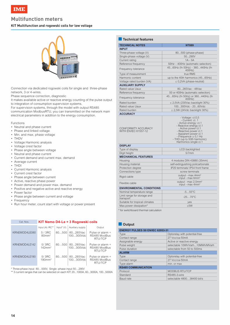
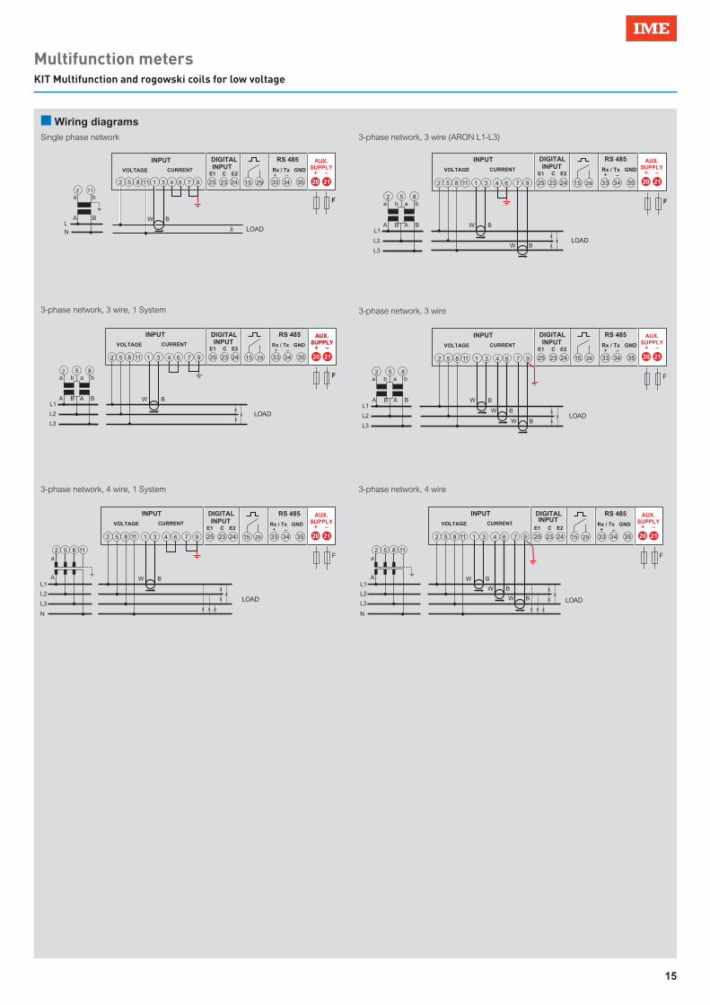
Multifunction metersKIT Multifunction and rogowski coils for low voltage
n Technical features
Connection via dedicated rogowski coils for single and three-phase network, 3 or 4-wires.Phase sequence correction, diagnosticIt makes available active or reactive energy counting of the pulse output to integration of consumption supervision systems.For supervision systems, through the model with output RS485 communication ModbusRTU, you can transmitted on the network main electrical parameters in addition to the energy consumption.
Functions• Neutral and phase current• Phase and linked voltage• Min. and max. phase voltage• THDV• Voltage Harmonic analysis• Voltage crest factor• Phase angle between voltage• Neutral and phase current• Current demand and current max. demand• Average current• THDI• Current Harmonic analysis• Current crest factor• Phase angle between current• Active, reactive phase power• Power demand and power max. demand• Positive and negative active and reactive energy• Power factor• Phase angle between current and voltage• Frequency• Run hour meter, count start with voltage or power present
TECHNICAL NOTES NT889INPUTThree-phase voltage (V) 80...500 (phase-phase)Single-phase voltage (V) 50...290VCurrent rating 1A - 5AReference frequency 50Hz – 400Hz (automatic selection)
Frequency tolerance 45...65Hz (fn 50Hz) – 360...440Hz (fn 400Hz)
Type of measurement true RMSHarmonic content up to the 40th harmonics (45...65Hz)Voltage rated burden (VA) ≤ 0,2VA (phase-neutral)AUXILIARY SUPPLYRated value Uaux 80...265Vac - 48VacReference frequency 50 or 400Hz (automatic selection)
Frequency tolerance 45…65Hz (fn 50Hz) or 360...440Hz (fn 400Hz)
Rated burden ≤ 2,5VA (230Vac backlight 30%)Rated value Uaux 100...300Vdc - 20...60VdcRated burden ≤ 2,5W (24Vdc backlight 30%)ACCURACY
CONFORMITY ACCURACY WITH EN/IEC 61557-12
- Voltage: cl.0,5- Current: cl. 1
- Active energy: cl.1- Reactive energy cl.1
- Active power cl.1- Reactive power cl.1- Apparent power cl.1- Frequence ± 0,1 Hz
- THD (up to 50th harmonic) Harmonics single cl.1
DISPLAYType of display LCD backlightedDigit height 5/7mmMECHANICAL FEATURESHousing 4 modules DIN 43880 (35mm)Housing material self-extinguishing policarbonateProtection degree IP20 terminals/ IP54 front frameConnections type screw terminals
Rigid cable output - max 4mm2
input - max 6mm2
Flexible cable output - max 2,5mm2
input - max 4mm2
ENVIRONMENTAL CONDITIONSNominal temperature range -5…55°CLimit range for storage and transport -25…70°C
Suitable for tropical climates yes Max.power dissipation* ≤5W
* for switchboard thermal calculation
Cat. Nos. KIT Nemo D4-Le + 3 Rogowski coils
Input (A) /RC** Input* (V) Auxiliary supply Output
KRNEMOD4LE080 5 / 3RC 80mm2
80…500 80...265Vac100...300Vdc
Pulse or alarm + RS485 ModBus
RTU/TCP
KRNEMOD4LE142 5/ 3RC 142mm2
80…500 80...265Vac100...300Vdc
Pulse or alarm + RS485 ModBus
RTU/TCP
KRNEMOD4LE190 5/ 3RC 190mm2
80…500 80...265Vac100...300Vdc
Pulse or alarm + RS485 ModBus
RTU/TCP
* Three-phase input 80…500V, Single -phase input 50…290V** 3 current ranges that can be selected on each KIT: 20...1000A, 60...3000A, 100...5000A
n Output
ENERGY PULSES S0 EN/IEC 62053-31Type Optorelay with potential-freeContact range 27 Vcc/ca-50mAAssignable energy Active or reactive energyPulse weight selectable 10Wh/Varh...10MWh/MVarhPulse duration selectable from 50 to 500msALARMType Optorelay with potential-freeContact range 27 Vcc/ca-50mAType alarm min. or maxRS485 COMMUNICATIONProtocol MODBUS RTU/TCPStandard RS485-3-wireBaud rate selectable 4800…38400 bit/s
15
Multifunction metersKIT Multifunction and rogowski coils for low voltage
AUX.SUPPLY
+ –
20 21
AUX.SUPPLY
+ –
20 21
AUX.SUPPLY
+ –
20 21
AUX.SUPPLY
+ –
20 21
AUX.SUPPLY
+ –
20 21
AUX.SUPPLY
+ –
20 212 5 8 111 3 6 94 7
a
A
b
BLN LOADX
2 11
INPUT
VOLTAGE CURRENT
15 29 33 34 35
RS 485
Rx / Tx GND + E1 E2 –
F
25 23 24
DIGITAL INPUT
C
X
XX
a
A
b
B
a
A
b
BL1
L2
L3
LOAD
2 5 8
INPUT
VOLTAGE CURRENT
2 5 8 1 3 6 94 711 15 29 33 34 35
RS 485
Rx / Tx GND + E1 E2 –
25 23 24
DIGITAL INPUT
C
F
X
XX
a
AL1
L2
L3
NX X X
LOAD
INPUT
VOLTAGE CURRENT
2 5 8 1 3 6 94 711
2 5 8 11
15 29 33 34 35
RS 485
Rx / Tx GND + E1 E2 –
25 23 24
DIGITAL INPUT
C
F
W B
W B
W B
X
XX
a
AL1
L2
L3
NX X X
LOAD
INPUT
VOLTAGE CURRENT
2 5 8 1 3 64 711
2 5 8 11
9 15 29 33 34 35
RS 485
Rx / Tx GND + E1 E2 –
25 23 24
DIGITAL INPUT
C
F
X
XX
a
A
b
B
a
A
b
BL1
L2
L3
LOAD
2 5 8
2 5 8 1 3 6 94 711 15 29 33 34 35
25 23 24
F
W B
W B
X
XX
a
A
b
B
a
A
b
BL1
L2
L3
LOAD
2 5 8
INPUT
VOLTAGE CURRENT
2 5 8 1 3 6 94 711 15 29 33 34 35
RS 485
Rx / Tx GND + E1 E2 –
25 23 24
DIGITAL INPUT
C
INPUT
VOLTAGE CURRENT
RS 485
Rx / Tx GND + E1 E2 –
DIGITAL INPUT
C
F
W B
W B
W B
AUX.SUPPLY
+ –
20 21
n Wiring diagramsSingle phase network
3-phase network, 3 wire, 1 System
3-phase network, 4 wire, 1 System
3-phase network, 3 wire (ARON L1-L3)
3-phase network, 4 wire
3-phase network, 3 wire
16
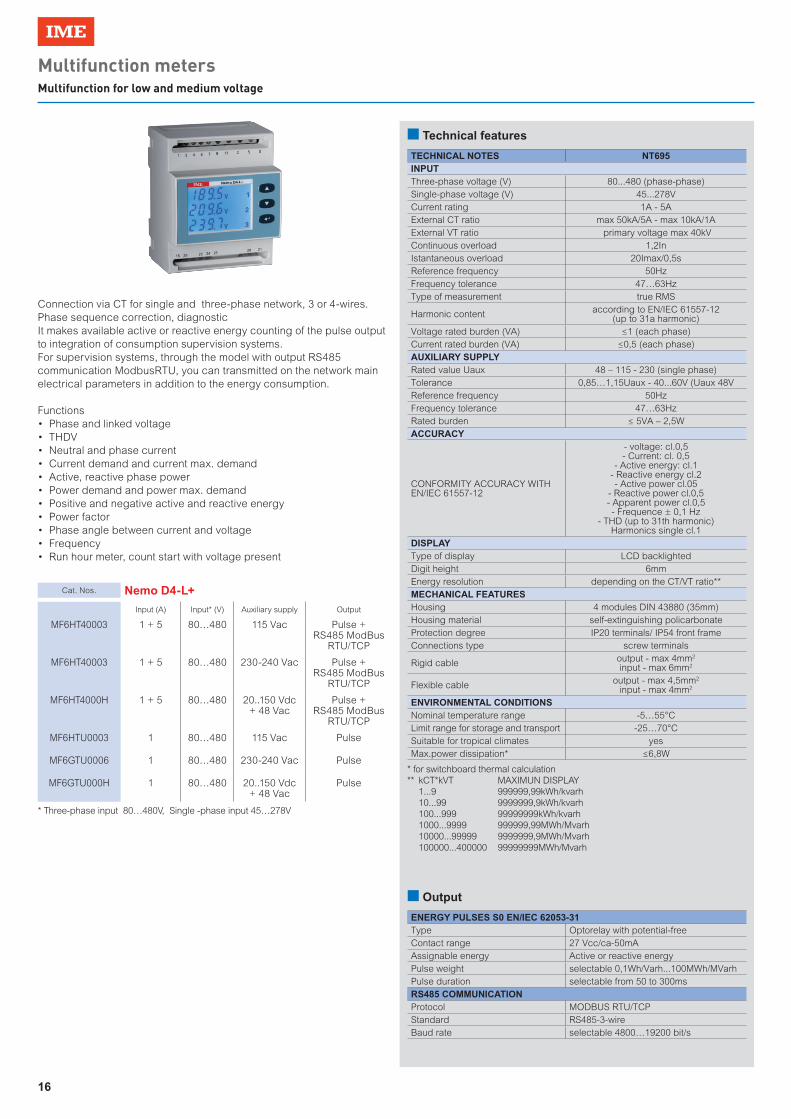
Multifunction metersMultifunction for low and medium voltage
Cat. Nos. Nemo D4-L+
Input (A) Input* (V) Auxiliary supply Output
MF6HT40003 1 + 5 80…480 115 Vac Pulse + RS485 ModBus
RTU/TCP
MF6HT40003 1 + 5 80…480 230-240 Vac Pulse + RS485 ModBus
RTU/TCP
MF6HT4000H 1 + 5 80…480 20..150 Vdc + 48 Vac
Pulse + RS485 ModBus
RTU/TCP
MF6HTU0003 1 80…480 115 Vac Pulse
MF6GTU0006 1 80…480 230-240 Vac Pulse
MF6GTU000H 1 80…480 20..150 Vdc + 48 Vac
Pulse
* Three-phase input 80…480V, Single -phase input 45…278V
Connection via CT for single and three-phase network, 3 or 4-wires.Phase sequence correction, diagnosticIt makes available active or reactive energy counting of the pulse output to integration of consumption supervision systems.For supervision systems, through the model with output RS485 communication ModbusRTU, you can transmitted on the network main electrical parameters in addition to the energy consumption.
Functions• Phase and linked voltage• THDV• Neutral and phase current• Current demand and current max. demand• Active, reactive phase power• Power demand and power max. demand• Positive and negative active and reactive energy• Power factor• Phase angle between current and voltage• Frequency• Run hour meter, count start with voltage present
n Technical features
TECHNICAL NOTES NT695INPUTThree-phase voltage (V) 80...480 (phase-phase)Single-phase voltage (V) 45...278VCurrent rating 1A - 5AExternal CT ratio max 50kA/5A - max 10kA/1AExternal VT ratio primary voltage max 40kVContinuous overload 1,2InIstantaneous overload 20Imax/0,5sReference frequency 50HzFrequency tolerance 47…63HzType of measurement true RMS
Harmonic content according to EN/IEC 61557-12 (up to 31a harmonic)
Voltage rated burden (VA) ≤1 (each phase)Current rated burden (VA) ≤0,5 (each phase)AUXILIARY SUPPLYRated value Uaux 48 – 115 - 230 (single phase)Tolerance 0,85…1,15Uaux - 40...60V (Uaux 48VReference frequency 50HzFrequency tolerance 47…63HzRated burden ≤ 5VA – 2,5WACCURACY
CONFORMITY ACCURACY WITH EN/IEC 61557-12
- voltage: cl.0,5- Current: cl. 0,5
- Active energy: cl.1- Reactive energy cl.2- Active power cl.05
- Reactive power cl.0,5- Apparent power cl.0,5- Frequence ± 0,1 Hz
- THD (up to 31th harmonic) Harmonics single cl.1
DISPLAYType of display LCD backlightedDigit height 6mmEnergy resolution depending on the CT/VT ratio**MECHANICAL FEATURESHousing 4 modules DIN 43880 (35mm)Housing material self-extinguishing policarbonateProtection degree IP20 terminals/ IP54 front frameConnections type screw terminals
Rigid cable output - max 4mm2
input - max 6mm2
Flexible cable output - max 4,5mm2
input - max 4mm2
ENVIRONMENTAL CONDITIONSNominal temperature range -5…55°CLimit range for storage and transport -25…70°CSuitable for tropical climates yes Max.power dissipation* ≤6,8W
* for switchboard thermal calculation** kCT*kVT MAXIMUN DISPLAY 1...9 999999,99kWh/kvarh 10...99 9999999,9kWh/kvarh 100...999 99999999kWh/kvarh 1000...9999 999999,99MWh/Mvarh 10000...99999 9999999,9MWh/Mvarh 100000...400000 99999999MWh/Mvarh
n Output
ENERGY PULSES S0 EN/IEC 62053-31Type Optorelay with potential-freeContact range 27 Vcc/ca-50mAAssignable energy Active or reactive energyPulse weight selectable 0,1Wh/Varh...100MWh/MVarhPulse duration selectable from 50 to 300msRS485 COMMUNICATIONProtocol MODBUS RTU/TCPStandard RS485-3-wireBaud rate selectable 4800…19200 bit/s
17
Multifunction metersMultifunction for low and medium voltage
2 5 8 111 3 6 94 7
S1
P1 S1
P1
LOAD
a
A
b
B
a
A
b
BL1
L2
L3X
XX
2 5 8
O U T P U T
33 34 35
RS 485 Rx / Tx GND
+ –
15 29 20
AUX.SUPPLY
212 5 8 1 3 6 94 7
S1
P1
S1
P1
LOAD
a
A
b
B
a
A
b
BL1
L2
L3
11
X
XX
2 5 8
O U T P U T
33 34 35
RS 485 Rx / Tx GND
+ –
15 29 20
AUX.SUPPLY
21
2 5 8 111 3 6 94 7
S1
P1
I N P U T
a
A
b
BL
NLOADX
2 5 811
O U T P U T
33 34 35
RS 485 Rx / Tx GND
+ –
15 29 20
AUX.SUPPLY
21 2 5 8 111 4 7
S1
P1 S1
P1
I N P U T
LOAD
3 6 9
a
A
b
B
a
A
b
BL1
L2
L3 X
XX
O U T P U T
33 34 35
RS 485 Rx / Tx GND
+ –
15 292 5 8
20
AUX.SUPPLY
21
X
XX
S1
P1 S1
P1
I N P U T
I N P U T
S1
P1
VOLTAGE CURRENT
a
A
b
B
a
A
b
BL1
L2
L3
LOAD
LOAD
2 5 8
2 5 8 11 1 3 4 6 7 9
O U T P U T
I N P U T O U T P U T
33 34 35
RS 485 Rx / Tx GND
+ –
15 29 20
AUX.SUPPLY
21
X
XX
S1
P1 S1
P1 S1
P1
a
AL1
L2
L3
NX X X LOAD
I N P U T
I N P U T
VOLTAGE CURRENT
2 5 8 11
2 5 8 11 1 3 4 6 7 9
O U T P U T
33 34 35
RS 485 Rx / Tx GND
+ –
15 29 20
AUX.SUPPLY
21
2 5 8 111 3 6 94 7
a
A
b
B
a
A
b
BL1
L2
L3 X
XX
2 5 833 34 35
RS 485 Rx / Tx GND
+ –
15 29 20 21
S1
P1
X
XX
S1
P1
a
A
L1
L2
L3
NX X X LOAD
I N P U T
VOLTAGE CURRENT
2 5 8 11
2 5 8 11 1 3 4 6 7 9
O U T P U T
33 34 35
RS 485 Rx / Tx GND
+ –
15 29 20 21
AUX.SUPPLY
AUX.SUPPLY
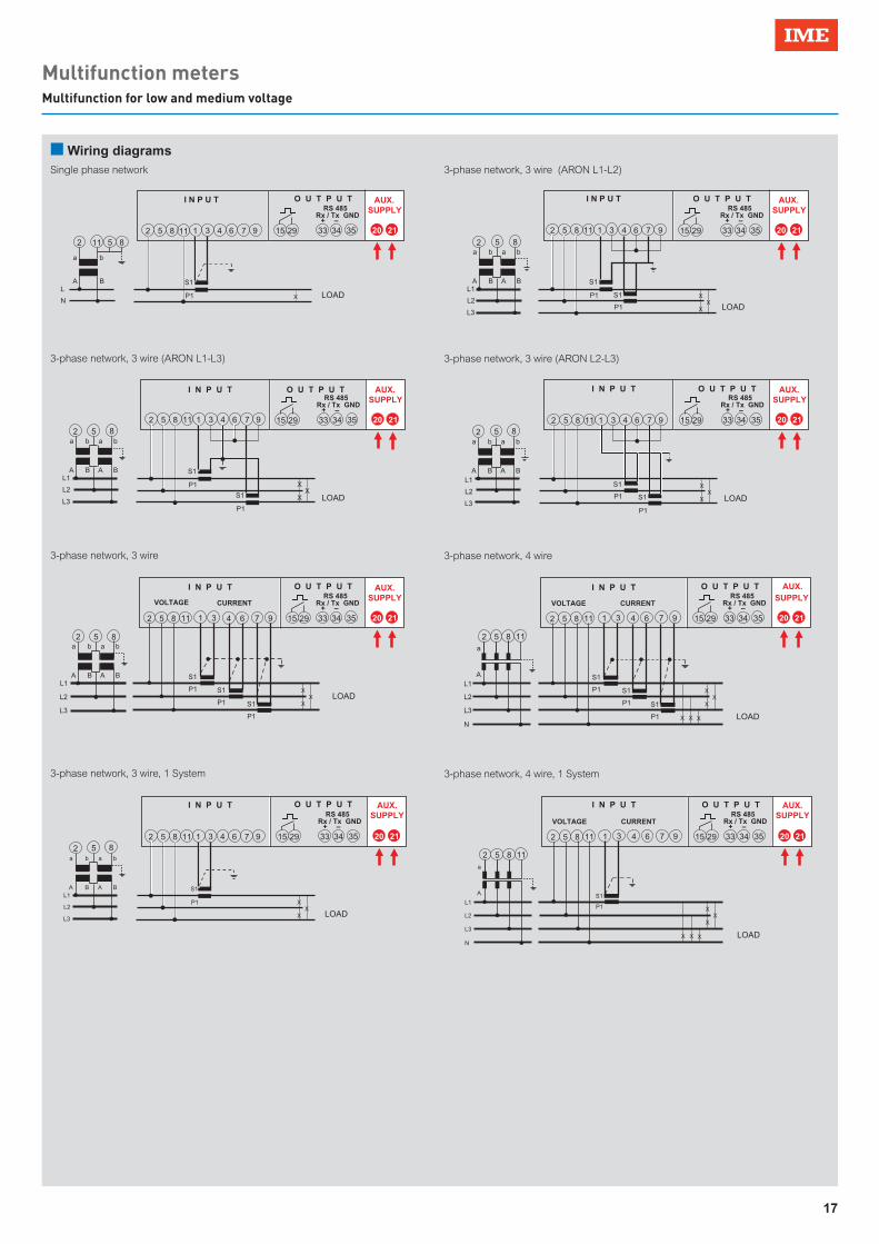
n Wiring diagramsSingle phase network
3-phase network, 3 wire, 1 System
3-phase network, 3 wire (ARON L1-L3)
3-phase network, 3 wire
3-phase network, 3 wire (ARON L1-L2)
3-phase network, 4 wire
3-phase network, 3 wire (ARON L2-L3)
3-phase network, 4 wire, 1 System

18
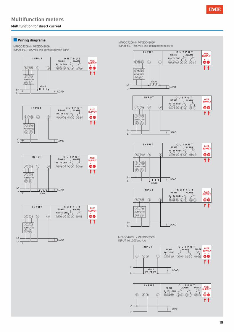
Multifunction metersMultifunction for direct current
n Technical features
n Output
Cat. Nos. Nemo D4-Dc
Input (A) Input* (V) Auxiliary supply Output
MF6DC4200H note 1 10...300V 20..150 Vdc + 48 Vac
Pulse + 2 alarms + RS485 ModBus
RTU
MF6DC42006 note 1 10...300V 230-240 Vac Pulse + 2 alarms + RS485 ModBus
RTU
MF6DC4206H note 1 50...1500V* 20..150 Vdc + 48 Vac
2 alarms + RS485 ModBus RTU
MF6DC42066 note 1 50...1500V* 230-240 Vac 2 alarms + RS485 ModBus RTU
* with AVMD150 adapter 2 modoluesnote 1Direct input up to 10A direct current, Input from shunt 60 – 100 – 150mV
TECHNICAL NOTES NT753INPUT
MF6DC4200H MF6DC42006
Direct input 10…300VdcInput impedance > 300kΩ
MF6DC4206H MF6DC42066
Input by adapter 50…1500VdcInput impedance > 3 MΩ
Instantaneous overload 10In/0,5sDirect Input 0…10AVoltage drop: ≤ 100mV (In10A)Input from shunt 60 – 100 – 150mVShunt primary 1…9999AAUXILIARY SUPPLYRated value Uaux ac 48 – 230VTolerance 0,85…1,15Uaux - 40...60V (Uaux 48V)Reference frequency 50HzFrequency tolerance 47…63HzRated burden ≤ 5VA – 3WRated value Uaux dc 20...150VdcRated burden ≤ 2WACCURACY
CONFORMITY ACCURACY WITH EN/IEC 61557-12
- voltage: ± 0,5% (10...100% Un)- Current: ± 0,5% (10...100% In)- Power: ± 1% (10...100% Pn)
DISPLAYType of display LCD backlightedDigit height 6mmReference frequency 50HzMECHANICAL FEATURES
Housing 4 modules DIN 43880 (35mm)(6 modules with AVMD150 adapter)
Housing material self-extinguishing policarbonateProtection degree IP20 terminals/ IP52 front frameConnections type screw terminals
Rigid cable output - max 4mm2 input - max 6mm2
Flexible cable output - max 4,5mm2 input - max 4mm2
ENVIRONMENTAL CONDITIONSNominal temperature range -5…55°CLimit range for storage and transport -25…70°CSuitable for tropical climates yesMax.power dissipation* ≤ 4W (Uax ca) - ≤ 4W (Uax cc)
* for switchboard thermal calculation
Direct voltage input by external adapter up to 1500VDirect current input or from shunt (selectable) - Direct input up to 10A direct current - Input from shunt 60 – 100 – 150mVIt makes available active or reactive energy counting of the pulse output to integration of consumption supervision systems.For supervision systems, through the model with output RS485 communication ModbusRTU, you can transmitted on the network main electrical parameters in addition to the energy consumption.
Functions• Voltage• Current• Power• Power demand and power max. demand• Positive energy• Negative energy• Positivi and negative Ah• Run hour meter, count start with voltage present
ENERGY PULSES S0 EN/IEC 62053-31Type Optorelay with potential-freeContact range 27 Vcc/ca-50mAAssignable energy Active or reactive energyPulse weight selectable 0,1kWh - 1kWh - 10kWh - 100kWhPulse duration selectable from 50 to 300msRS485 COMMUNICATIONProtocol MODBUS RTUStandard RS485-3-wireBaud rate selectable 4800…19200 bit/sOUTPUT RELAYType 2 relays with potential-freeOutput function 2 singularly-programmable indipendent alarms
Contact range 5A 250Vac cosϕ 1 - 3A 250Vac cosϕ 0,4 - 5A 30Vdc
19
Multifunction metersMultifunction for direct current
2 3 4 1
I N P U T
LOADX
O U T P U T
33 34 35
RS 485
Rx / Tx GND + –
20 21
+ –
shuntL+
L-
8 9
1ALARM PULSE
10 11
2
17 29 2 1 3 4
I N P U T
LOADX
O U T P U T
I N P U T O U T P U T
33 34 35
RS 485
Rx / Tx GND + –
20 21+ –
L+
L-
8 9
1
10 11
2
17 29
ALARM PULSE
2 17 29 1 3
I N P U T
LOADX
O U T P U T
33 34 35
RS 485
Rx / Tx GND + –
20 21
+ –
shuntL+
L-
8 9
1ALARM
10 11
2
2 17 29
HV+ HV-
HV+ HV-
AVMFD150
2 17 29 4 3
LOADX
33 34 35
RS 485
Rx / Tx GND + –
20 21
+ –
L+
L-
8 9
1ALARM
10 11
2
2 17 29
AVMFD150
2 17 29 3 1
I N P U T
LOADX
O U T P U T
33 34 35
RS 485
Rx / Tx GND + –
20 21
+ –
shunt
L+
L-
8 9
1ALARM
10 11
2
2 17 29
AVMFD150
2 17 29 3 4
I N P U T
LOADX
O U T P U T
I N P U T O U T P U T
33 34 35
RS 485
Rx / Tx GND + –
20 21
+ –
L+
L-
8 9
1ALARM
10 11
2
2 17 29
AVMFD150
2 17 29 1 3
I N P U T
LOADX
O U T P U T
33 34 35
RS 485
Rx / Tx GND + –
20 21
+ –
shunt
L+
L-
8 9
1ALARM
10 11
2
2 17 29
AVMFD150
2 17 29 4 3
LOADX
33 34 35
RS 485
Rx / Tx GND + –
20 21
+ –
L+
L-
8 9
1ALARM
10 11
2
2 17 29
AVMFD150
2 17 29 3 1
I N P U T
LOADX
O U T P U T
33 34 35
RS 485
Rx / Tx GND + –
20 21
+ –
shunt
L+
L-
8 9
1ALARM
10 11
2
2 17 29
AVMFD150
2 17 29 3 4
I N P U T
LOADX
O U T P U T
33 34 35
RS 485
Rx / Tx GND + –
20 21
+ –
L+
L-
8 9
1ALARM
10 11
2
2 17 29
AVMFD150
AUX.SUPPLY
AUX.SUPPLY
AUX.SUPPLY
AUX.SUPPLY
AUX.SUPPLY
AUX.SUPPLY
AUX.SUPPLY
AUX.SUPPLY
AUX.SUPPLY
AUX.SUPPLY
HV+ HV-
HV+ HV-
HV+ HV- HV+ HV-
HV+ HV-
HV+ HV-
MF6DC4200H - MF6DC42006INPUT 10...300Vcc /dc
n Wiring diagrams
MF6DC4206H - MF6DC42066INPUT 50...1500Vdc line connected with earth
MF6DC4206H - MF6DC42066INPUT 50...1500Vdc line insulated from earth

20
Multifunction metersFlush mounting multifunction for low voltage
Cat. Nos. Nemo 72-b
Input (A) Input (V) Auxiliary supply Output
MF7GM0009A 5 195(340) - 260(450)Vac Self supplied -
MF7GM2009A 5 195(340) - 260(450)Vac Self supplied 2 alarms
MF7GM0008A 1 195(340) - 260(450)Vac Self supplied -
MF7GM2008A 1 195(340) - 260(450)Vac Self supplied 2 alarms
MF7GT0009A 5 340...450Vac Self supplied -
MF7GT2009A 5 340...450Vac Self supplied 2 alarms
MF7GT0008A 1 340...450Vac Self supplied -
MF7GT2008A 1 340...450Vac Self supplied 2 alarms
n Technical features
n Wiring diagrams
n Dimensions
Connection via CT for single and three-phase network, 3 or 4-wires.Phase sequence correction, diagnostic
Functions• Phase and linked voltage• Neutral and phase current• Current demand and current max. demand• Power demand and power max. demand• Power factor• Frequency• Run hour meter, count start with voltage present • State of alarms
TECHNICAL NOTES NT651INPUTThree-phase voltage (V) 340...450V (phase-phase)Single-phase voltage (V) 195...260VCurrent rating 1A - 5A
External CT ratio
5/10/15/20/25/30/40/50/60/70/75/80/100/120/125/150/160/200/250/300/400/500/600/700/750/800/1000/1200/1250/1500/1600/2000/2500/3000/3200/4000/5000/
6000/7000/7500/8000AContinuous overload 1,2InIstantaneous overload 20Imax/0,5sReference frequency 50HzFrequency tolerance 47…63HzType of measurement true RMSHarmonic content up to the 21th harmonicVoltage rated burden (VA) ≤0,5 (each phase)Current rated burden (VA) ≤0,5 (each phase)AUXILIARY SUPPLY
Self-supplied L(1) - N (mod. MF7GM..)L1 - L2 (mod. MF7GT..)
Rated burden ≤ 2VA - ≤ 2,5VA (with alarms)ACCURACY
CONFORMITY ACCURACY WITH EN/IEC 61557-12
- voltage: ± 0,5% (340...450V phase - phase)- Current: ± 0,5% (10...120% In)
- Neutral current: ± 2%- Power: ± 1% P - ± 2% Q / S (10...120%
Pn/Qn/Sn cosϕ 0,5 ind...0,5cap)- Power factor: ± 2%
- Frequency: ± 0,2 HzDISPLAYType of display LCD backlightedDigit height 6mmMECHANICAL FEATURESHousing flush mounting (panel cutout 68x68mm)Front frame 72x72mmHousing material self-extinguishing makrolonProtection degree IP20 terminals/ IP54 front frameConnections type screw terminals
Rigid cable output - max 4mm2
input - max 4mm2
Flexible cable output - max 2,5mm2
input - max 2,5mm2
ENVIRONMENTAL CONDITIONSNominal temperature range -5…55°CLimit range for storage and transport -25…70°C
Suitable for tropical climates yes Max.power dissipation* ≤6,8W
* for switchboard thermal calculation
68
68
72
72
81
7
2 5 8 11 1 4 7 3
L3
L1
L2
N
S1
P1 S1
P1 S1
P1
I N P U T
X
XX
X X X
3130 4140
ALARMS
I N P U T ALARMS
1 2I N P U T ALARMS
3130 4140
1 2
2 5 8 1 3 4 7
N
LS1
P1
11
X
3130 4140
1 2
2 5 8 1 4 7
L3
L1
L2
S1
P1
S1
P1X
XX
I N P U T ALARMS
3130 4140
1 2
2 5 8 1 4 7
L3
L1
L2
S1
P1 S1
P1 X
XX
Three-phase network 4-wire Single-phase network
68
68
72
72
81
7
2 5 8 11 1 4 7 3
L3
L1
L2
N
S1
P1 S1
P1 S1
P1
I N P U T
X
XX
X X X
3130 4140
ALARMS
I N P U T ALARMS
1 2I N P U T ALARMS
3130 4140
1 2
2 5 8 1 3 4 7
N
LS1
P1
11
X
3130 4140
1 2
2 5 8 1 4 7
L3
L1
L2
S1
P1
S1
P1X
XX
I N P U T ALARMS
3130 4140
1 2
2 5 8 1 4 7
L3
L1
L2
S1
P1 S1
P1 X
XX
Three-phase network 3-wire (ARON L1-L3)
Three-phase network 3-wire (ARON L1-L2)
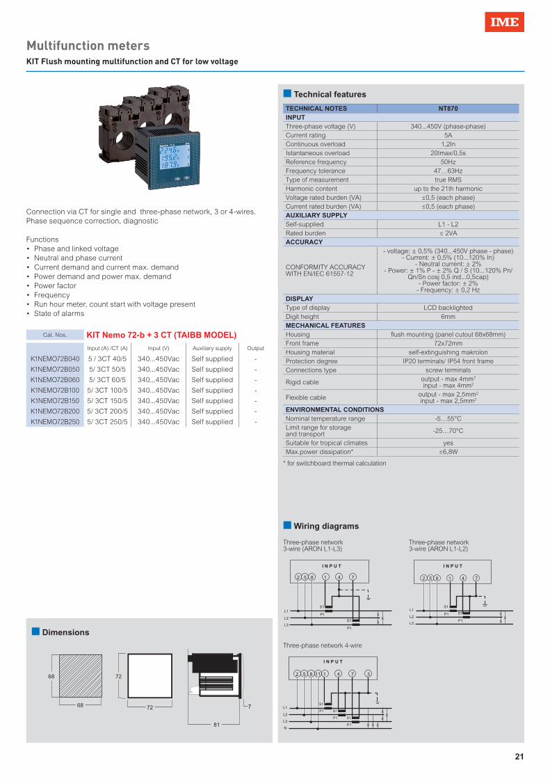
21
Multifunction metersKIT Flush mounting multifunction and CT for low voltage
Cat. Nos. KIT Nemo 72-b + 3 CT (TAIBB MODEL)
Input (A) /CT (A) Input (V) Auxiliary supply Output
K1NEMO72B040 5 / 3CT 40/5 340...450Vac Self supplied -
K1NEMO72B050 5/ 3CT 50/5 340...450Vac Self supplied -
K1NEMO72B060 5/ 3CT 60/5 340...450Vac Self supplied -
K1NEMO72B100 5/ 3CT 100/5 340...450Vac Self supplied -
K1NEMO72B150 5/ 3CT 150/5 340...450Vac Self supplied -
K1NEMO72B200 5/ 3CT 200/5 340...450Vac Self supplied -
K1NEMO72B250 5/ 3CT 250/5 340...450Vac Self supplied -
2 5 8 11 1 4 7 3
L3
L1
L2
N
S1
P1 S1
P1 S1
P1
I N P U T
X
XX
X X X
I N P U T
2 5 8 1 4 7
L3
L1
L2
S1
P1
S1
P1
X
XX
I N P U T
2 5 8 1 4 7
L3
L1
L2
S1
P1 S1
P1 X
XX
n Technical features
n Wiring diagrams
n Dimensions
Connection via CT for single and three-phase network, 3 or 4-wires.Phase sequence correction, diagnostic
Functions• Phase and linked voltage• Neutral and phase current• Current demand and current max. demand• Power demand and power max. demand• Power factor• Frequency• Run hour meter, count start with voltage present • State of alarms
* for switchboard thermal calculation
68
68
72
72
81
7
2 5 8 11 1 4 7 3
L3
L1
L2
N
S1
P1 S1
P1 S1
P1
I N P U T
X
XX
X X X
3130 4140
ALARMS
I N P U T ALARMS
1 2I N P U T ALARMS
3130 4140
1 2
2 5 8 1 3 4 7
N
LS1
P1
11
X
3130 4140
1 2
2 5 8 1 4 7
L3
L1
L2
S1
P1
S1
P1X
XX
I N P U T ALARMS
3130 4140
1 2
2 5 8 1 4 7
L3
L1
L2
S1
P1 S1
P1 X
XX
TECHNICAL NOTES NT870INPUTThree-phase voltage (V) 340...450V (phase-phase)Current rating 5AContinuous overload 1,2InIstantaneous overload 20Imax/0,5sReference frequency 50HzFrequency tolerance 47…63HzType of measurement true RMSHarmonic content up to the 21th harmonicVoltage rated burden (VA) ≤0,5 (each phase)Current rated burden (VA) ≤0,5 (each phase)AUXILIARY SUPPLYSelf-supplied L1 - L2 Rated burden ≤ 2VA ACCURACY
CONFORMITY ACCURACY WITH EN/IEC 61557-12
- voltage: ± 0,5% (340...450V phase - phase)- Current: ± 0,5% (10...120% In)
- Neutral current: ± 2%- Power: ± 1% P - ± 2% Q / S (10...120% Pn/
Qn/Sn cosj 0,5 ind...0,5cap)- Power factor: ± 2%
- Frequency: ± 0,2 HzDISPLAYType of display LCD backlightedDigit height 6mmMECHANICAL FEATURESHousing flush mounting (panel cutout 68x68mm)Front frame 72x72mmHousing material self-extinguishing makrolonProtection degree IP20 terminals/ IP54 front frameConnections type screw terminals
Rigid cable output - max 4mm2
input - max 4mm2
Flexible cable output - max 2,5mm2
input - max 2,5mm2
ENVIRONMENTAL CONDITIONSNominal temperature range -5…55°CLimit range for storage and transport -25…70°C
Suitable for tropical climates yes Max.power dissipation* ≤6,8W
Three-phase network 4-wire
Three-phase network 3-wire (ARON L1-L3)
Three-phase network 3-wire (ARON L1-L2)

22
Multifunction metersFlush mounting multifunction for low voltage
n Technical features
Connection via CT for single and three-phase network, 3 or 4-wires.Phase sequence correction, diagnosticIt makes available active or reactive energy counting of the pulse output to integration of consumption supervision systems.For supervision systems, through the model with output RS485 communication ModbusRTU, you can transmitted on the network main electrical parameters in addition to the energy consumption.
Functions• Phase and linked voltage• Min. and max. phase voltage• THDV• Voltage Harmonic analysis• Voltage crest factor• Phase angle between voltage• Neutral and phase current• Current demand and current max. demand• Average current• THDI• Current Harmonic analysis• Current crest factor• Phase angle between current• Active, reactive phase power• Power demand and power max. demand• Positive and negative active and reactive energy• Power factor• Phase angle between current and voltage• Frequency• Run hour meter, count start with voltage or power present
Cat. Nos. Nemo 72-Le
Input (A) Input* (V) Auxiliary supply Output
MF72411 1 + 5 80…500 80...265Vac 100...300Vdc
Pulse or alarm
MF72421 1 + 5 80…500 80...265Vac 100...300Vdc
Pulse or alarm + RS485 ModBus RTU/TCP
MF724B1 1 + 5 80…500 80...265Vac 100...300Vdc
Pulse or alarm + RS485 BACnet
MF72412 1 + 5 80…500 20...60 Vdc Pulse or alarm
MF72422 1 + 5 80…500 20...60 Vdc Pulse or alarm + RS485 ModBus RTU/TCP
MF724B2 1 + 5 80…500 20...60 Vdc Pulse or alarm + RS 485 BACnet
* Three-phase input 80…500V, Single -phase input 50…290V
TECHNICAL NOTES NT879INPUTThree-phase voltage (V) 80...500 (phase-phase)Single-phase voltage (V) 50...290VCurrent rating 1A - 5AExternal CT ratio max 50kA/5A - max 10kA/1AExternal VT ratio primary voltage max 1200VContinuous overload 1,2InIstantaneous overload 20Imax/0,5sReference frequency 50Hz – 400Hz (automatic selection)Frequency tolerance 45...65Hz (fn 50Hz) – 360...440Hz (fn 400Hz)Type of measurement true RMSHarmonic content up to the 50th harmonics (45...65Hz)Voltage rated burden (VA) ≤ 0,2VA (phase-neutral)Current rated burden (VA) ≤ 1VA (for phase)AUXILIARY SUPPLYRated value Uaux 80...265Vac - 48VacReference frequency 50 or 400Hz (automatic selection)Frequency tolerance 45…65Hz (fn 50Hz) or 360...440Hz (fn 400Hz)Rated burden ≤ 2,5VA (230Vac backlight 30%)Rated value Uaux 100...300Vdc - 20...60VdcRated burden ≤ 2,5W (24Vdc backlight 30%)ACCURACY
CONFORMITY ACCURACY WITH EN/IEC 61557-12
- voltage: cl.0,5- Current: cl. 0,5
- Active energy: cl.0,5- Reactive energy cl.1- Active power cl.05
- Reactive power cl.1- Apparent power cl.1- Frequence ± 0,1 Hz
- THD (up to 50th harmonic) Harmonics single cl.1
DISPLAYType of display LCD backlightedDigit height 6mmEnergy resolution depending on the CT/VT ratio**MECHANICAL FEATURESHousing flush mounting (panel cutout 68x68mm)Front frame 72x72mmHousing material self-extinguishing makrolonProtection degree IP20 terminals/ IP54 front frameConnections type screw terminals
Rigid cable output - max 4mm2
input - max 6mm2
Flexible cable output - max 2,5mm2
input - max 4mm2
ENVIRONMENTAL CONDITIONSNominal temperature range -5…55°CLimit range for storage and transport -25…70°CSuitable for tropical climates yes Max.power dissipation* ≤5W
* for switchboard thermal calculation** kCT*kVT MAXIMUN DISPLAY 1...9 999999,99kWh/kvarh 10...99 9999999,9kWh/kvarh 100...999 99999999kWh/kvarh 1000...9999 999999,99MWh/Mvarh 10000...99999 9999999,9MWh/Mvarh
n Dimensions
68
68
72
72
81
7
2 5 8 11 1 4 7 3
L3
L1
L2
N
S1
P1 S1
P1 S1
P1
I N P U T
X
XX
X X X
3130 4140
ALARMS
I N P U T ALARMS
1 2I N P U T ALARMS
3130 4140
1 2
2 5 8 1 3 4 7
N
LS1
P1
11
X
3130 4140
1 2
2 5 8 1 4 7
L3
L1
L2
S1
P1
S1
P1X
XX
I N P U T ALARMS
3130 4140
1 2
2 5 8 1 4 7
L3
L1
L2
S1
P1 S1
P1 X
XX
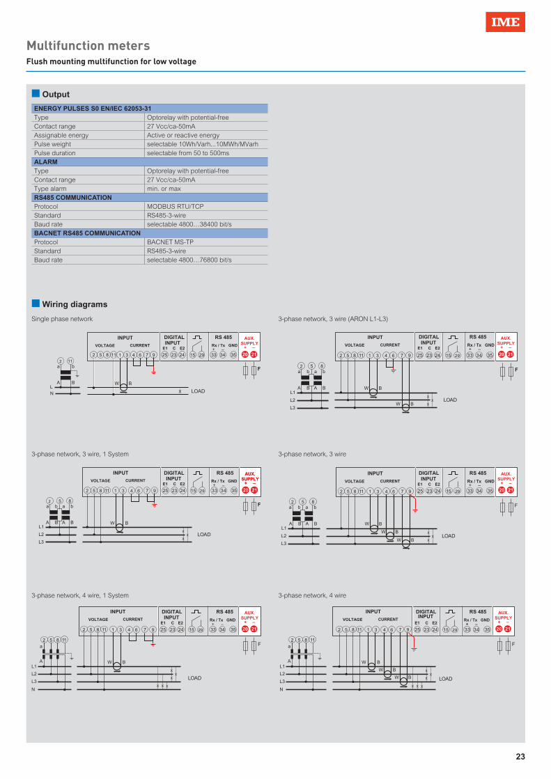
23
Multifunction metersFlush mounting multifunction for low voltage
n Output
ENERGY PULSES S0 EN/IEC 62053-31Type Optorelay with potential-freeContact range 27 Vcc/ca-50mAAssignable energy Active or reactive energyPulse weight selectable 10Wh/Varh...10MWh/MVarhPulse duration selectable from 50 to 500msALARMType Optorelay with potential-freeContact range 27 Vcc/ca-50mAType alarm min. or maxRS485 COMMUNICATIONProtocol MODBUS RTU/TCPStandard RS485-3-wireBaud rate selectable 4800…38400 bit/sBACNET RS485 COMMUNICATIONProtocol BACNET MS-TPStandard RS485-3-wireBaud rate selectable 4800…76800 bit/s
AUX.SUPPLY
+ –
20 21
AUX.SUPPLY
+ –
20 21
AUX.SUPPLY
+ –
20 21
AUX.SUPPLY
+ –
20 21
AUX.SUPPLY
+ –
20 21
AUX.SUPPLY
+ –
20 212 5 8 111 3 6 94 7
a
A
b
BLN LOADX
2 11
INPUT
VOLTAGE CURRENT
15 29 33 34 35
RS 485
Rx / Tx GND + E1 E2 –
F
25 23 24
DIGITAL INPUT
C
X
XX
a
A
b
B
a
A
b
BL1
L2
L3
LOAD
2 5 8
INPUT
VOLTAGE CURRENT
2 5 8 1 3 6 94 711 15 29 33 34 35
RS 485
Rx / Tx GND + E1 E2 –
25 23 24
DIGITAL INPUT
C
F
X
XX
a
AL1
L2
L3
NX X X
LOAD
INPUT
VOLTAGE CURRENT
2 5 8 1 3 6 94 711
2 5 8 11
15 29 33 34 35
RS 485
Rx / Tx GND + E1 E2 –
25 23 24
DIGITAL INPUT
C
F
W B
W B
W B
X
XX
a
AL1
L2
L3
NX X X
LOAD
INPUT
VOLTAGE CURRENT
2 5 8 1 3 64 711
2 5 8 11
9 15 29 33 34 35
RS 485
Rx / Tx GND + E1 E2 –
25 23 24
DIGITAL INPUT
C
F
X
XX
a
A
b
B
a
A
b
BL1
L2
L3
LOAD
2 5 8
2 5 8 1 3 6 94 711 15 29 33 34 35
25 23 24
F
W B
W B
X
XX
a
A
b
B
a
A
b
BL1
L2
L3
LOAD
2 5 8
INPUT
VOLTAGE CURRENT
2 5 8 1 3 6 94 711 15 29 33 34 35
RS 485
Rx / Tx GND + E1 E2 –
25 23 24
DIGITAL INPUT
C
INPUT
VOLTAGE CURRENT
RS 485
Rx / Tx GND + E1 E2 –
DIGITAL INPUT
C
F
W B
W B
W B
AUX.SUPPLY
+ –
20 21
n Wiring diagrams
Single phase network 3-phase network, 3 wire (ARON L1-L3)
3-phase network, 3 wire, 1 System
3-phase network, 4 wire, 1 System
3-phase network, 3 wire
3-phase network, 4 wire

24
Multifunction metersFlush mounting multifunction for low voltage
Connection via CT for single and three-phase network, 4-wires.Phase sequence correction, diagnosticIt makes available active or reactive energy counting of the pulse output to integration of consumption supervision systems.For supervision systems, through the model with output RS485 communication ModbusRTU, you can transmitted on the network main electrical parameters in addition to the energy consumption.
Functions• Phase and linked voltage• Min. and max. phase voltage• THDV• Neutral and phase current• Current demand and current max. demand• Average current• THDI• Active, reactive phase power• Power demand and power max. demand• Positive and negative active and reactive energy• Power factor• Frequency• Run hour meter, count start with voltage or power present
Cat. Nos. Nemo 96 HDe
Input (A) Input* (V) Auxiliary supply Output
MF96E06 5 500 self-supplied Pulse + RS485
n Technical features
* Three-phase input 500V, Single -phase input 230-240V
TECHNICAL NOTES NT900INPUTThree-phase voltage (V) 500 (phase-phase)Single-phase voltage (V) 230-240VCurrent rating 5AExternal CT ratio max 50kA/5AContinuous overload 1,2InIstantaneous overload 20Imax/0,5sReference frequency 50Hz – 400Hz (automatic selection)
Frequency tolerance 45...65Hz (fn 50Hz) – 360...440Hz (fn 400Hz)
Type of measurement true RMSHarmonic content up to the 50th harmonicsVoltage rated burden (VA) ≤ 0,1VA (phase-neutra)Current rated burden (VA) ≤ 1VA (for phase)AUXILIARY SUPPLY
Nominal voltage Taken from measurement(self-supplied)
ACCURACY
CONFORMITY ACCURACY WITH EN/IEC 61557-12
- voltage: cl.0,5- Current: cl. 0,5
- Active energy: cl.1- Reactive energy cl.1
- Active power cl.1- Reactive power cl.1- Apparent power cl.1- Frequence ± 0,1Hz
- THD cl.1DISPLAYType of display LCD backlightedDigit height 6/9mmEnergy resolution depending on the CT ratio **MECHANICAL FEATURESHousing flush mounting (panel cutout 92x92mm)Front frame 96x96mmHousing material self-extinguishing policarbonateProtection degree IP20 terminals/ IP54 front frameConnections type screw terminalsRigid cable max 4,5mm2
Flexible cable max 2,5mm2
ENVIRONMENTAL CONDITIONSNominal temperature range -5…55°CLimit range for storage and transport -25…70°CSuitable for tropical climates yes Max.power dissipation* ≤5W
* for switchboard thermal calculation** kCT MAXIMUN DISPLAY 1...9 999999,99kWh/kvarh 10...99 9999999,9kWh/kvarh 100...999 99999999kWh/kvarh 1000...9999 999999,99MWh/Mvarh
n Output
ENERGY PULSES S0 EN/IEC 62053-31Type Optorelay with potential-freeContact range 27 Vcc/ca-50mAAssignable energy Active or reactive energyPulse weight selectable 10Wh/Varh...10MWh/MVarhPulse duration selectable from 50 to 500msRS485 COMMUNICATIONProtocol MODBUS RTU/TCPStandard RS485-3-wireBaud rate selectable 4800…38400 bit/s

25
Multifunction metersSelection table
n Dimensions
62 12
92
9692
96
81*
Option module*
X
XX
S1
P1 S1
P1 S1
P1 X X X
LOAD
INPUTVOLTAGE CURRENT
2 5 8 1 3 6 94 711 TI T2 3 4 5
RS 485
Rx / Tx GND + –
2 5 8 111 3 6 94 7
S1
P1 LOADX
INPUTVOLTAGE CURRENT
TI T2 3 4 5
RS 485
Rx / Tx GND + –
n Wiring diagrams
Single phase network 3-phase network, 4 wire

26
Multifunction metersFlush mounting multifunction for low voltage
Connection via CT for single and three-phase network, 3 or 4-wires.Phase sequence correction, diagnosticCan be accessorised with an additional modules.It makes available active or reactive energy counting of the pulse output to integration of consumption supervision systems.For supervision systems, through the model with output RS485 communication ModbusRTU, you can transmitted on the network main electrical parameters in addition to the energy consumption.
Functions• Phase and linked voltage• Min. and max. phase voltage• THDV• Voltage Harmonic analysis• Voltage crest factor• Neutral and phase current• Current demand and current max. demand• Average current• THDI• Current Harmonic analysis• Current crest factor• Active, reactive phase power• Power demand and power max. demand• Positive and negative active and reactive energy• Power factor• Frequency• Run hour meter, count start with voltage or power present
Cat. Nos. Nemo 96 HDLe
Input (A) Input* (V) Auxiliary supply Output
MF96411 1 + 5 80…500 80...265Vac100...300Vdc
Pulse + 1 additional modules
MF96412 1 + 5 80…500 16...60Vdc Pulse + 1 additional modules
MF96421 1 + 5 80…500 80...265Vac100...300Vdc
Pulse + RS485 ModBus RTU/TCP + 1 additional
modules
MF96422 1 + 5 80…500 16...60Vdc Pulse + RS485 ModBus RTU/TCP + 1 additional modules
Cat. Nos. Additional modules
Descriptions
IF96001 Module RS485 Modbus RTU/TCP
IF96012 Module RS485 Modbus RTU/TCP + memory
IF96002 Module RS232 Modbus RTU/TCP
IF96007A Module Profibus EN50170 - DP0
IF96009 Module LonWorks
IF96013 Module M-Bus EN1434-3
IF96014 Module RS485 BACnet MS-TP
IF96015 Module Ethernet
n Technical features
IF96001 IF96002
IF96015
* Three-phase input 80…500V, Single -phase input 50…290V
TECHNICAL NOTES NT854INPUTThree-phase voltage (V) 80...500 (phase-phase)Single-phase voltage (V) 50...290VCurrent rating 1A - 5AExternal CT ratio max 50kA/5A - max 10kA/1AExternal VT ratio primary voltage max 1200V Continuous overload 1,2InIstantaneous overload 20Imax/0,5sReference frequency 50Hz – 400Hz (automatic selection)
Frequency tolerance 45...65Hz (fn 50Hz) – 360...440Hz (fn 400Hz)
Type of measurement true RMSHarmonic content up to the 50th harmonicsVoltage rated burden (VA) ≤ 0,1VA (phase-neutra)Current rated burden (VA) ≤ 1VA (for phase)AUXILIARY SUPPLYRated value Uaux 80...265VacReference frequency 50 or 400Hz (automatic selection)
Frequency tolerance 45…65Hz (fn 50Hz) or 360...440Hz (fn 400Hz)
Rated burden ≤ 2,5VA (230Vac backlight 30% without external modules)
Rated value Uaux 100...300Vdc Rated burden ≤ 3,5W (without modules, 110Vdc)ACCURACY
CONFORMITY ACCURACY WITH EN/IEC 61557-12
- voltage: cl.0,5- Current: cl. 0,5
- Active energy: cl.0,5- Reactive energy cl.1- Active power cl.05
- Reactive power cl.1- Apparent power cl.1- Frequence ± 0,1Hz
- THD cl.1DISPLAYType of display LCD backlightedDigit height 8/12mmEnergy resolution depending on the CT/VT ratio**MECHANICAL FEATURESHousing flush mounting (panel cutout 92x92mm)Front frame 96x96mmHousing material self-extinguishing policarbonateProtection degree IP20 terminals/ IP54 front frameConnections type screw terminalsRigid cable max 4,5mm2
Flexible cable max 2,5mm2
ENVIRONMENTAL CONDITIONSNominal temperature range -5…55°CLimit range for storage and transport -25…70°CSuitable for tropical climates yes Max.power dissipation* ≤5W
n Output
ENERGY PULSES S0 EN/IEC 62053-31Type Optorelay with potential-freeContact range 27 Vcc/ca-50mAAssignable energy Active or reactive energyPulse weight selectable 10Wh/Varh...10MWh/MVarhPulse duration selectable from 50 to 500msRS485 COMMUNICATIONProtocol MODBUS RTU/TCPStandard RS485-3-wireBaud rate selectable 4800…38400 bit/sADDITIONAL MODULESN. max installable module 1Installation position A
* for switchboard thermal calculation** kCT*kVT MAXIMUN DISPLAY 1...9 999999,99kWh/kvarh 10...99 9999999,9kWh/kvarh 100...999 99999999kWh/kvarh 1000...9999 999999,99MWh/Mvarh 10000...99999 9999999,9MWh/Mvarh
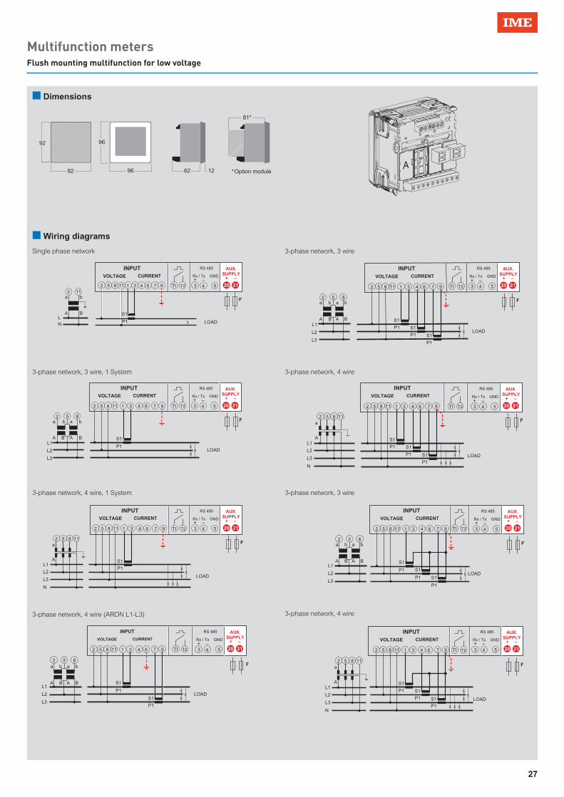
27
Multifunction metersFlush mounting multifunction for low voltage
A
n Dimensions
62 12
92
9692
96
81*
Option module*
AUX.SUPPLY
+ –
20 21
AUX.SUPPLY
+ –
20 21
X
XX
S1
P1
a
A
b
B
a
A
b
BL1
L2
L3
LOAD
2 5 8
INPUTVOLTAGE CURRENT
2 5 8 1 3 6 94 711 TI T2 3 4 5
RS 485
Rx / Tx GND + –
F
X
XX
S1
P1 S1
P1 S1
P1
a
AL1
L2
L3
NX X X
LOAD
INPUTVOLTAGE CURRENT
2 5 8 1 3 6 94 711
2 5 8 11
TI T2 3 4 5
RS 485
Rx / Tx GND + –
F
AUX.SUPPLY
+ –
20 21
AUX.SUPPLY
+ –
20 21
X
XX
S1
P1
a
AL1
L2
L3
NX X X
LOAD
INPUTVOLTAGE CURRENT
2 5 8 1 3 64 711
2 5 8 11
9 TI T2 3 4 5
RS 485
Rx / Tx GND + –
F
F
X
XX
S1
P1 S1
P1 S1
P1
a
A
b
B
a
A
b
BL1
L2
L3
LOAD
2 5 8
INPUTVOLTAGE CURRENT
2 5 8 1 3 6 94 711 TI T2 3 4 5
RS 485
Rx / Tx GND + –
F
AUX.SUPPLY
+ –
20 21
AUX.SUPPLY
+ –
20 21
X
XX
S1
P1 S1
P1 S1
P1
a
AL1
L2
L3
NX X X
LOAD
INPUTVOLTAGE CURRENT
2 5 8 1 3 6 94 711
2 5 118
TI T2 3 4 5
RS 485
Rx / Tx GND + –
F
X
XX
S1
P1
S1
P1
a
A
b
B
a
A
b
BL1
L2
L3
LOAD
2 5 8
INPUT
VOLTAGE CURRENT
2 5 8 1 3 6 94 711 TI T2 3 4 5
RS 485
Rx / Tx GND + –
AUX.SUPPLY
+ –
20 21
AUX.SUPPLY
+ –
20 212 5 8 111 3 6 94 7
S1
P1
a
A
b
BLN LOADX
2 11
INPUTVOLTAGE CURRENT
TI T2 3 4 5
RS 485
Rx / Tx GND + –
F
X
XX
S1
P1 S1
P1 S1
P1
a
A
b
B
a
A
b
BL1
L2
L3
LOAD
2 5 8
INPUTVOLTAGE CURRENT
2 5 8 1 3 6 94 711 TI T2 3 4 5
RS 485
Rx / Tx GND + –
F
n Wiring diagrams
Single phase network
3-phase network, 3 wire, 1 System
3-phase network, 4 wire, 1 System
3-phase network, 4 wire (ARON L1-L3)
3-phase network, 3 wire
3-phase network, 3 wire
3-phase network, 4 wire
3-phase network, 4 wire

28
Multifunction metersFlush mounting multifunction for low voltage
n Technical features
IF96001 IF96002
IF96015 IF96009
Cat. Nos. Nemo 96 HD
Input (A) Input* (V) Auxiliary supply Output
MF96001 1 + 5 80…500 80...265Vac100...300Vdc
up 4 additional modules
MF96002 1 + 5 80…500 16...60Vdc up 4 additional modules
Cat. Nos. Additional modules
Descriptions
IF96001 Module RS485 Modbus RTU/TCP
IF96012 Module RS485 Modbus RTU/TCP + memory
IF96002 Module RS232 Modbus RTU/TCP
IF96007A Module Profibus EN50170 - DP0
IF96009 Module LonWorks
IF96013 Module M-Bus EN1434-3
IF96014 Module RS485 BACnet MS-TP
IF96015 Module Ethernet
IF96003 Module with 2 energy pulse outputs (SPST)
IF96004 Module with 2 x 0/4..20mA analogue outputs
IF96005 Module with 2 alarm relay outputs (SPST)
IF96006 Neutral current measurement from CT /1A or 5A programmable
IF96016 Module temperature measurement 2 inputs from PT100
IF96010 Module with 2 input SPST-NO 2 relay outputs SPST-NO
IF96011 Module with 2 input 12/24Vcc 2 relay outputs SPST-NO
* Three-phase input 80…500V, Single -phase input 50…290V
Connection via CT for single and three-phase network, 3 or 4-wires.Phase sequence correction, diagnostic.Can be accessorised with up to 4 additional modules.
Functions• Phase and linked voltage• Min. and max. phase voltage• THDV• Neutral and phase current• Current demand and current max. demand• Average current• THDI• Active, reactive phase power• Power demand and power max. demand• Positive and negative active and reactive energy• Power factor• Frequency• Run hour meter, count start with voltage or power present
TECHNICAL NOTES NT680INPUTThree-phase voltage (V) 80...500 (phase-phase)Single-phase voltage (V) 50...290VCurrent rating 1A - 5AExternal CT ratio max 50kA/5A - max 10kA/1AExternal VT ratio primary voltage max 1200V Continuous overload 1,2InIstantaneous overload 20Imax/0,5sReference frequency 50Hz Frequency tolerance 45...63HzType of measurement true RMSVoltage rated burden (VA) ≤ 0,1VA (phase-neutral)Current rated burden (VA) ≤ 1VA (for phase)AUXILIARY SUPPLYRated value Uaux 80...265VacReference frequency 50Frequency tolerance 45…63Hz)
Rated burden ≤ 2,5VA (230Vac backlight 30% without external modules)
Rated value Uaux 100...300Vdc 11...60VdcRated burden ≤ 3,5W (without modules)ACCURACY
CONFORMITY ACCURACY WITH EN/IEC 61557-12
- Voltage: cl.0,5- Current: cl. 0,5
- Active energy: cl.0,5- Reactive energy cl.2- Active power cl.05
- Reactive power cl.1- Apparent power cl.1
- Frequence cl.0,5 - Power factor cl.0,5
- THD cl.2DISPLAYType of display LCD backlightedDigit height 12mmEnergy resolution depending on the CT/VT ratio**MECHANICAL FEATURESHousing flush mounting (panel cutout 92x92mm)Front frame 96x96mmHousing material self-extinguishing policarbonateProtection degree IP20 terminals/ IP54 front frameConnections type screw terminalsRigid cable max 4,5mm2
Flexible cable max 2,5mm2
ENVIRONMENTAL CONDITIONSNominal temperature range -5…55°CLimit range for storage and transport -25…70°CSuitable for tropical climates yes Max.power dissipation* ≤5W
n Output
ADDITIONAL MODULESN. max installable module 1Installation position A-B-C-D
A B C D
* for switchboard thermal calculation** kCT*kVT MAXIMUN DISPLAY 1...9 999999,99kWh/kvarh 10...99 9999999,9kWh/kvarh 100...999 99999999kWh/kvarh 1000...9999 999999,99MWh/Mvarh 10000...99999 9999999,9MWh/Mvarh 100000...400000 99999999MWh/Mvarh

29
Multifunction metersFlush mounting multifunction for low voltage
n Dimensions
62 12
92
9692
96
81*
Option module*
2 5 8 111 3 6 94 7
S1
P1
a
A
b
BL
N LOADX
20 21
2 11
INPUT
VOLTAGE CURRENT
F
AUX.SUPPLY
+ –
INPUT
VOLTAGE CURRENT
X
XX
S1
P1
a
A
b
B
a
A
b
BL1
L2
L3
2 5 8
20 212 5 8 1 3 6 94 711
F
AUX.SUPPLY
+ –
INPUT
VOLTAGE CURRENT
X
XX
S1
P1
a
AL1
L2
L3
NX X X
20 212 5 8 1 3 64 711
2 5 8 11
9
F
LOAD
AUX.SUPPLY
+ –
X
XX
S1
P1 S1
P1 S1
P1
a
AL1
L2
L3
NX X X
LOAD
20 212 5 8 1 3 6 94 711
2 5 8 11F
INPUT
VOLTAGE CURRENT
AUX.SUPPLY
+ –
X
XX
S1
P1 S1
P1 S1
P1
a
A
b
B
a
A
b
BL1
L2
L3
LOAD
2 5 8
20 212 5 8 1 3 6 94 711
F
INPUT
VOLTAGE CURRENT
AUX.SUPPLY
+ –
X
XX
S1
P1
S1
P1
a
A
b
B
a
A
b
BL1
L2
L3
LOAD
2 5 8
20 212 5 8 1 3 6 94 711
F
INPUT
VOLTAGE CURRENT
AUX.SUPPLY
+ –
n Wiring diagrams
Single phase network
3-phase network, 3 wire, 1 System
3-phase network, 4 wire, 1 System
3-phase network, 4 wire (ARON L1-L3)
3-phase network, 3 wire
3-phase network, 4 wire

30
Multifunction metersFlush mounting multifunction for low, medium and high voltage
n Technical features
Connection via CT for single and three-phase network, 3 or 4-wires.Phase sequence correction, diagnostic.Can be accessorised with up to 4 additional modules.
Functions• Phase and linked voltage• Min. and max. phase voltage• THDV• Voltage Harmonic analysis• Voltage crest factor• Phase angle between voltage• Neutral and phase current• Current demand and current max. demand• Average current• THDI• Current Harmonic analysis• Current crest factor• Phase angle between current• Active, reactive phase power• Power demand and power max. demand• Positive and negative active and reactive energy• Power factor• Phase angle between current and voltage• Frequency• Run hour meter, count start with voltage or power present
IF96001 IF96002
IF96015 IF96018
Cat. Nos. Nemo 96 HD+
Input (A) Input* (V) Auxiliary supply Output
MF96021 1 + 5 80…690 80...265Vac100...300Vdc
up 4 additional modules
MF96022 1 + 5 80…690 16...60Vdc up 4 additional modules
Cat. Nos. Additional modules
Descriptions
IF96001 Module RS485 Modbus RTU/TCP
IF96012 Module RS485 Modbus RTU/TCP + memory
IF96002 Module RS232 Modbus RTU/TCP
IF96007A Module Profibus EN50170 - DP0
IF96009 Module LonWorks
IF96013 Module M-Bus EN1434-3
IF96014 Module RS485 BACnet MS-TP
IF96015 Module Ethernet
IF96018 1 Radio transmitter module 868 MHz
IF96003 Module with 2 energy pulse outputs (SPST)
IF96004 Module with 2 x 0/4..20mA analogue outputs
IF96005 Module with 2 alarm relay outputs (SPST)
IF96006 Neutral current measurement from CT /1A or 5A programmable
IF96016 Module temperature measurement 2 inputs from PT100
IF96010 Module with 2 input SPST-NO 2 relay outputs SPST-NO1 Complete with power unit, pen-type steerable aerial + extension cable of 20cm. A
transceiver gateway IFMTR01 must be provided. on RS485
* Three-phase input 80…690, Single -phase input 230V
TECHNICAL NOTES NT904INPUTThree-phase voltage (V) 80...690 (phase-phase)Single-phase voltage (V) 230VCurrent rating 1A - 5AExternal CT ratio max 50kA/5A - max 10kA/1AExternal VT ratio primary voltage max 150kVContinuous overload 1,2InIstantaneous overload 20Imax/0,5sReference frequency 50Hz Frequency tolerance 45...63HzType of measurement true RMSVoltage rated burden (VA) ≤ 0,1VA (phase-neutral)Current rated burden (VA) ≤ 0,2VA (for phase)AUXILIARY SUPPLYRated value Uaux 80...265VacReference frequency 50Frequency tolerance 45…63Hz)
Rated burden ≤ 2,5VA (230Vac backlight 30% without external modules)
Rated value Uaux 100...300Vdc 11...60VdcRated burden ≤ 3,5W (without modules)ACCURACY
CONFORMITY ACCURACY WITH EN/IEC 61557-12
- voltage: cl.0,5- Current: cl. 0,5
- Active energy: cl.0,5- Reactive energy cl.2- Active power cl.05
- Reactive power cl.1- Apparent power cl.1
- Frequence cl.0,5 - Power factor cl.0,5
- THD cl.2DISPLAYType of display LCD backlightedDigit height 8/12mmEnergy resolution depending on the CT/VT ratio**MECHANICAL FEATURESHousing flush mounting (panel cutout 92x92mm)Front frame 96x96mmHousing material self-extinguishing policarbonateProtection degree IP20 terminals/ IP54 front frameConnections type screw terminalsRigid cable max 4,5mm2
Flexible cable max 2,5mm2
ENVIRONMENTAL CONDITIONSNominal temperature range -5…55°CLimit range for storage and transport -25…70°CSuitable for tropical climates yes Max.power dissipation* ≤5W
n Output
ADDITIONAL MODULESN. max installable module 1Installation position A-B-C-D
A B C D
* for switchboard thermal calculation** kCT*kVT MAXIMUN DISPLAY 1...9 999999,99kWh/kvarh 10...99 9999999,9kWh/kvarh 100...999 99999999kWh/kvarh 1000...9999 999999,99MWh/Mvarh 10000...99999 9999999,9MWh/Mvarh 100000...400000 99999999MWh/Mvarh

31
Multifunction metersFlush mounting multifunction for low, medium and high voltage
n Dimensions
62 12
92
9692
96
81*
Option module*
n Wiring diagrams
2 5 8 111 3 6 94 7
S1
P1
a
A
b
BLN
LOADX
20 21
AUX.SUPPLY
+ –
2 11
INPUTVOLTAGE CURRENT
F
X
XX
S1
P1
a
A
b
B
a
A
b
BL1
L2
L3
LOAD
2 5 8
INPUTVOLTAGE CURRENT
2 5 8 1 3 6 94 711
F
20 21
AUX.SUPPLY
+ –
X
XX
S1
P1
a
A
X X X
LOAD
2 5 8 1 3 6 94 711
2 5 8 11
L1
L2
L3
N
F
INPUTVOLTAGE CURRENT
20 21
AUX.SUPPLY
+ –
INPUTVOLTAGE CURRENT
X
XX
S1
P1
S1
P1
a
A
b
B
a
A
b
BL1
L2
L3
LOAD
2 5 8
2 5 8 1 3 6 94 711
F
20 21
AUX.SUPPLY
+ –
X
XX
S1
P1 S1
P1 S1
P1
a
AL1
L2
L3
NX X X
LOAD
INPUTVOLTAGE CURRENT
2 5 8 1 3 6 94 711
2 5 118F
20 21
AUX.SUPPLY
+ –
X
XX
S1
P1 S1
P1 S1
P1
a
AL1
L2
L3
NX X X
LOAD
INPUTVOLTAGE CURRENT
2 5 8 1 3 6 94 711
2 5 8 11F
20 21
AUX.SUPPLY
+ –
X
XX
S1
P1 S1
P1 S1
P1
a
A
b
B
a
A
b
BL1
L2
L3
LOAD
2 5 8
INPUTVOLTAGE CURRENT
2 5 8 1 3 6 94 711
F
20 21
AUX.SUPPLY
+ –
X
XX
S1
P1 S1
P1 S1
P1
a
A
b
B
a
A
b
BL1
L2
L3
LOAD
2 5 8
INPUTVOLTAGE CURRENT
2 5 8 1 3 6 94 711
F
20 21
AUX.SUPPLY
+ –
Single phase network
3-phase network, 3 wire, 1 System
3-phase network, 4 wire, 1 System
3-phase network, 4 wire (ARON L1-L3)
3-phase network, 3 wire
3-phase network, 4 wire
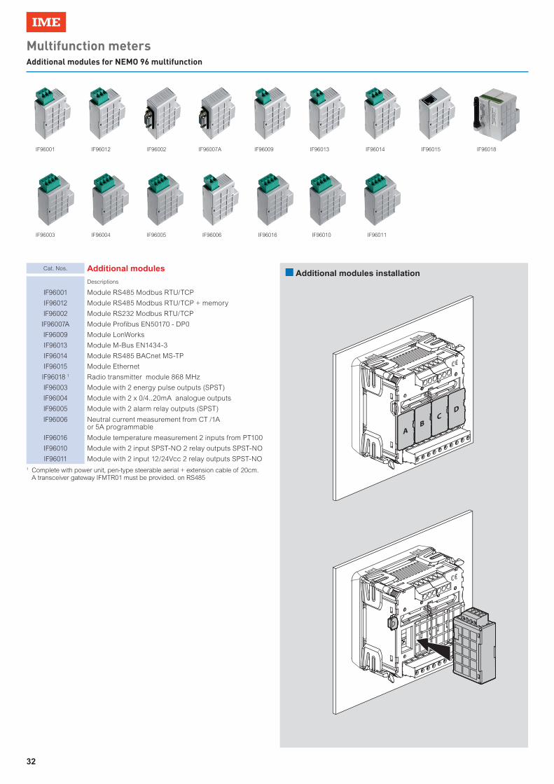
32
Multifunction metersAdditional modules for NEMO 96 multifunction
Cat. Nos. Additional modules
Descriptions
IF96001 Module RS485 Modbus RTU/TCP
IF96012 Module RS485 Modbus RTU/TCP + memory
IF96002 Module RS232 Modbus RTU/TCP
IF96007A Module Profibus EN50170 - DP0
IF96009 Module LonWorks
IF96013 Module M-Bus EN1434-3
IF96014 Module RS485 BACnet MS-TP
IF96015 Module Ethernet
IF96018 1 Radio transmitter module 868 MHz
IF96003 Module with 2 energy pulse outputs (SPST)
IF96004 Module with 2 x 0/4..20mA analogue outputs
IF96005 Module with 2 alarm relay outputs (SPST)
IF96006 Neutral current measurement from CT /1A or 5A programmable
IF96016 Module temperature measurement 2 inputs from PT100
IF96010 Module with 2 input SPST-NO 2 relay outputs SPST-NO
IF96011 Module with 2 input 12/24Vcc 2 relay outputs SPST-NO
n Additional modules installation
IF96001
IF96003 IF96004 IF96005 IF96006 IF96016 IF96010 IF96011
IF96012 IF96002 IF96007A IF96009 IF96013 IF96014 IF96015 IF96018
AB
CD
1 Complete with power unit, pen-type steerable aerial + extension cable of 20cm. A transceiver gateway IFMTR01 must be provided. on RS485

33
Multifunction metersAdditional modules for NEMO 96 multifunction - Selection table
A B C D
Cat. Nos. Technical notes Descriptions
n°maxinstallable
Installationposition
NEMO 96HDL E NEMO 96HD NEMO 96HD+
COMMUNICATION MODULES 1
IF96001 NT675 RS485 Modbus RTU/TCP 1 A ● ● ●
IF96012 NT704RS485 Modbus RTU/TCP
+ memory1 A ● ● ●
IF96002 NT676 RS232 Modbus RTU/TCP 1 A ● ● ●
IF96007A NT682 Profibus EN50170 - DP0 1 A ● ● ●
IF96009 NT684 LonWorks 1 A ● ● ●
IF96013 NT707 M-Bus EN1434-3 1 A ● ● ●
IF96014 NT743 RS485 BACnet MS-TP 1 A ● ● ●
IF96015 NT785 Ethernet 1 A ● ● ●
IF96018 2 NT856 Radio transmitter module 868 MHz 1 A ●
OUTPUT MODULES
IF96003 NT677 2 energy pulse outputs (SPST) 2 A - B - C - D ● ●
IF96004 NT678 2 x 0/4..20mA analogue outputs 2 C - D ● ●
IF96005 NT679 2 alarm relay outputs (SPST) 2 A - B - C - D ● ●
MEASUREMENT MODULES
IF96006 NT683Neutral current measurement
from CT /1A or 5A programmable1 C ● ●
IF96016 NT810 Temperature measurement 2 inputs from PT100 1 D ● ●
I/O MODULE
IF96010 NT702 2 input SPST-NO 2 relay outputs SPST-NO 2 C - D ● ●
IF96011 NT703 2 input 12/24Vcc 2 relay outputs SPST-NO 2 C - D ●
1 Communication modules are as an alternative to them2 Complete with power unit, pen-type steerable aerial + extension cable of 20cm. A transceiver gateway IFMTR01 must be provided. on RS485

34
Note

35
Note

AD-E
X/IM
E-M
F17B
/GB
- 0
9/20
17
Via Travaglia, 7 20094 Corsico (MI)% : +39 02 44 878.1 Fax +39 02 45 03 [email protected]