Embed Size (px)
Citation preview

Multiband Antenna-Receiver Integration using an RF Multiplexer with Sensitivity-Constrained Design
S.M. Hasan and S. W. Ellingson
Wireless at Virginia Tech
RF MultiplexerHasan / Ellingson – July 10, 2008
Wireless at Virginia Tech
Bradley Dept. of ECE, Virginia Tech,
Blacksburg, VA 24060
July 10, 2008

Motivation (1/2) Direct Conversion CMOS RFIC
For Multiband Multimode Radios (MMR)s
Superhet Design-
Power Hungry/ Large/ Complex/ Expensive
Direct Conversion Design-
Low Cost/ Small Size/ Low Power/No IR Filter
Cons: I/Q imbalance, 1/f noise, IP2, Initial BPF
Problems with direct conversion design can now be largely mitigated by:
2/14
RF MultiplexerHasan / Ellingson – July 10, 2008
RFIC from Motorola Research Lab5 RX Paths , 3 TX PathsTunes 100 - 2500 MHz (continuous) BW: 4.25 kHz – 10 MHz (many steps) Sideband Rejection ~ 40 dB, up to 60 dBInternal DDSs for LO generationExcellent mitigation of 1/f noise
largely mitigated by:
• Implementing design to be robust to variations
• Exploiting availability of nearby logic to enable radio to tweak chip as needed
G. Cafaro et al., “A 100 MHz – 2.5 GHz Direct Conversion CMOS
Transceiver for SDR Applications,” 2007 IEEE RFIC Symp., June 2007.
VT RFIC Board

Motivation (2/2)
Focus of this paper
System Diagram of the prototype MMR
3/14
RF MultiplexerHasan / Ellingson – July 10, 2008
Developing a prototype radio capable of operation over a large range of frequency bands now in use for public safety applications.

What’s the idea?
Ratio of external noise to front end noise,
Irreducible
Sensitivity depends on signal to noise ratio
External noise can be very strong in practical scenarios, especially at low frequencies (below ~400 MHz)
If γ is large, additional effort to minimize |Γ| or TFE will have little effect on sensitivity
If acceptable γ can be achieved for a poor
4/14
RF MultiplexerHasan / Ellingson – July 10, 2008
front end noise,
Reflection co-efficient,
If acceptable γ can be achieved for a poor |Γ|, improvements in |Γ| are actually counterproductive, since this complicates the design
Our idea is to design a multiplexer, which may be poorly matched with the antenna impedance, in such a way that the front end is dominated by the external noise and provide acceptable sensitivity

Antenna Model (1/2)
Theveninmodel of antenna
TTG* model of antenna impedance
* T. Tang, Q. Tieng, M. Gunn, “Equivalent Circuit of a Dipole Antenna Using Frequency-Independent Lumped Elements,” IEEE Trans
on Ant. & Prop. Vol 41, No 1. Jan 1993.
5/14
RF MultiplexerHasan / Ellingson – July 10, 2008
h = heighta = radius
pF pF
uH
kOhm
on Ant. & Prop. Vol 41, No 1. Jan 1993.

200
300
400
Circuit model & impedance for a 20 cm monopole of 5 mm radius
Antenna Model (2/2)
6/14
RF MultiplexerHasan / Ellingson – July 10, 2008
100 200 300 400 500 600 700 800 900
-300
-200
-100
0
100
Frequency [MHz]
Zant [
Ω]
Real Zant
Imag Zant

Mean noise temperature,
[K]b
T af−=
External (“Environmental”) Noise
External Noise limits receiver’s sensitivity if -
T T>
7/14
RF MultiplexerHasan / Ellingson – July 10, 2008
Standard deviation with respect to location
Compiled from ITU-R: ’Radio Noise’, P.372-8, 2003.
ext FET T>

“Optimum” Noise FigureThis is the noise figure required of an amplifier attached to an antenna if the output is to be dominated by external noise by a factor of 10 in 90% of locations of the indicated type.
Optimum in the
8/14
RF MultiplexerHasan / Ellingson – July 10, 2008
Prevents over-specifying receiver NF
Can be interpreted as a loosened constraint
Optimum in the sense that any lower noise figure does not significantly increase sensitivity (only cost).
These particular results assume lossless, perfectly matched antenna with no ground loss.
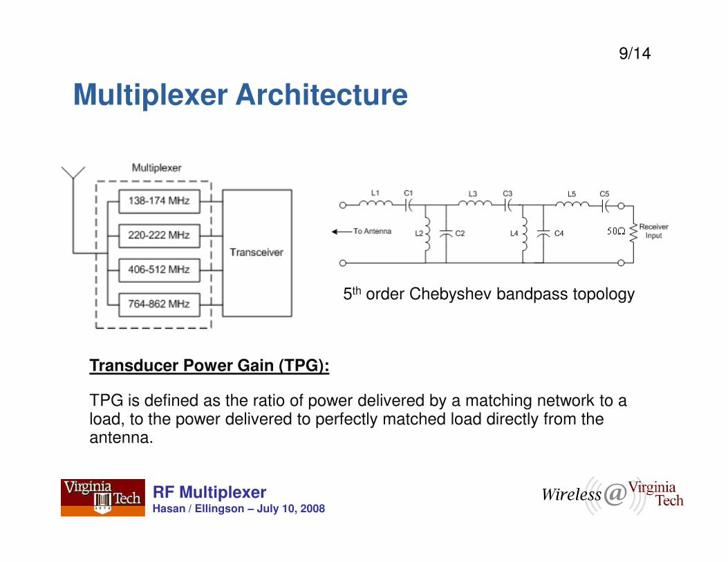
Multiplexer Architecture
9/14
RF MultiplexerHasan / Ellingson – July 10, 2008
Transducer Power Gain (TPG):
TPG is defined as the ratio of power delivered by a matching network to a load, to the power delivered to perfectly matched load directly from the antenna.
5th order Chebyshev bandpass topology

-30
-25
-20
-15
-10
-5
0
TP
G [dB
]
Results: Before Optimization
10/14
RF MultiplexerHasan / Ellingson – July 10, 2008
100 200 300 400 500 600 700 800 900-50
-45
-40
-35
-30
Frequency [MHz]
•Solid Line: Antenna Impedance is assumed as constant 50Ω
•Dotted Line: Antenna Impedance is assumed as TTG impedance

-30
-25
-20
-15
-10
-5
0
TP
G [dB
]
Results: After Optimization
Design Criteria:
(1) The ratio of external (unavoidable) noise to internally generated noise at the output of a receiver front end should be large
11/14
RF MultiplexerHasan / Ellingson – July 10, 2008
100 200 300 400 500 600 700 800 900-50
-45
-40
-35
Frequency [MHz]
Channels are jointly optimized using GENESYSChannel 1 & 2 are optimized to achieve maximum flatnessChannel 3 & 4 are optimized to get maximum TPG
(2) The TPG should be reasonably flat over the passband

10
15
20
25
Ra
tio o
f E
xte
rnal to
Inte
rnal
Nois
e (
γ ) [L
inea
r]
F = 1.0 dB
F = 2.0 dB
“External noise dominance” inVHF-High and 220 MHz bands
Results: Noise Dominance
12/14
RF MultiplexerHasan / Ellingson – July 10, 2008
130 140 150 160 170 180 190 200 210 220 2300
5
Frequency [MHz]
Component Values

138-174 MHz 220-222 MHz406-512 MHz764-900 MHz
Touchscreen
Audio
Off-the-shelf antenna
Prototype MMR
100 200 300 400 500 600 700 800 900 1000-250
-200
-150
-100
-50
0
50
100
150
Frequency (MHz)
Zant[ ΩΩ ΩΩ
]
Real Zant
Imag Zant
Impedance of actual antenna used (ANT-433-CW)
13/14
RF MultiplexerHasan / Ellingson – July 10, 2008
Three board stack integrates antenna, RF Mux, transceiver RFIC, ADC / DAC,ref. freq. synthesizer
Altera EP2S60 FPGA Board
Ethernet
Battery underneath
100 200 300 400 500 600 700 800 900-50
-45
-40
-35
-30
-25
-20
-15
-10
-5
0
Frequency (MHz)
TP
G (d
B)
Multiplexer using ANT-433-CW
Summary Remarks Key Idea: RF multiplexer optimized to antenna impedance with external
noise dominance constraint, allows good performance in multiple bands
Principal advantage over reconfigurable matching techniques:
Simultaneous access to multiple bands
Good result with 20 cm 5 mm rod antenna, but less good performance with commercial (433 MHz) antenna
14/14
RF MultiplexerHasan / Ellingson – July 10, 2008
with commercial (433 MHz) antenna
Co-design of antenna and multiplexer may be advantageous
Challenges:
• Requires amplifiers with little better NF than commonly used
• Realizing small filter footprint
Project Website:http://www.ece.vt.edu/swe/chamrad/
U.S. Dept. of JusticeNational Institute of Justice
Grant 2005-IJ-CX-K018
Acknowledgement: