Embed Size (px)
Citation preview

Multi-user MIMO
Transmission in LTE Uplink
Adrià Yébenes Creus Summer Semester 2015

Multi-user Transmission in LTE Uplink Page 1
Index
Chapter Page
1. Abstract 2
2. Introduction 3
3. The Vienna LTE Simulator 5
4. Development of the MU-MIMO simulator 6
5. System model 7
6. First MU-MIMO simulations 9
7. The SUS scheduler 15
8. The MMSE filter 28
9. Successive Interference Cancellation (SIC) 46
10. Conclusions 59
11. References 65
12. Appendix: Introduction of the channel estimation error 66

Multi-user Transmission in LTE Uplink Page 2
Multi-user MIMO Transmission in LTE Uplink
1. Abstract
In this paper, MU-MIMO transmission in LTE Uplink is implemented in a simulator and
its performance is evaluated. Using the Matlab based Vienna LTE uplink simulator, new
features are added to the system to be able to evaluate and discuss the capabilities of the
multi user transmission in a LTE mobile communication network. After the basic MU-
MIMO functions, a Round Robin scheduler and a zero forcing filter in the receiver, some
extra implementations are carried out to make a more complete simulator able to make
a wide range of different simulations. A new scheduler, based on a greedy multi-user
implementation, the possibility of including channel estimation errors, and two new
receivers based on a minimum mean square error (MMSE) filter and a successive
interference cancellation (SIC) filter based on MMSE are implemented and several
simulations about are carried out.

Multi-user Transmission in LTE Uplink Page 3
2. Introduction Mobile communications has become during the last decades a main way of
communication around the world. From the first generation mobile phones, used only to
send and receive calls, until nowadays, with the addition of internet and data services in
the new devices, mobile communications importance has been increased exponentially.
Currently mobile communications main use is data connection, for example in internet
navigation or use of applications, and voice services have been disowned to a secondary
plane. The volume of data traffic from mobile communications is increasing every year
and forecasts agree that this trend will not change. This is caused both by the increasing
number of users and the volume of data consumed by each user.
The importance of mobile communications is undeniable. It is not necessary to see all
the statistics that support this fact, only beholding the amount of people in the streets, in
public transports, in bars or in any other place using a mobile communication device it is
already easy to realize the great usage of this technology.
Nowadays LTE is the newest standard of mobile communications network currently
working, still growing in number of users and usage. As this technology is already
implemented and being exploited, new techniques are being studied to enhance the LTE
performance, in order to deploy the next evolution of LTE, as known as LTE advanced
(LTE-A). One of the main proposals in new releases to enhance the LTE system is the
multi antenna access (MIMO). This technology is based on spatial multiplexing, where
two or more flow data streams can be transmitted at the same time and at the same
frequency, and be successfully detected at the receiver, thanks to the usage of multiple
antennas. The MIMO technology can be implemented in two different ways: the first one
is based on one single user and one base station, where the user transmits different data
streams for each one of his antennas, and the receiver detects each of these streams
employing his different antennas. This method, known as SU-MIMO, single user MIMO,
can be useful in private networks with one or a small number of users, but in a mobile
network with several users it would not be practical. For this reason there is a second
mode of MIMO, called MU-MIMO, multi user MIMO, where different users can transmit
simultaneously to the base station, which has multiple antennas, and each user’s data is

Multi-user Transmission in LTE Uplink Page 4
detected in the receiver, by combining the signal received in all its antennas employing
joint detection. With this method, the receiver is able to separate the data of the
different users, which enhances the system performance and the spectral efficiency
considerably with respect to the single user case. This method is expected to be a very
important key to improve the performance of LTE. For this reason, it will be studied in
this work using Matlab program, to create a simulator capable to ascertain its
performance and to evaluate the expected improvements that this will provide.
This work will be based on the implementation in Matlab of a multi-user MIMO
simulator in LTE uplink. In order to make it possible, the existing Vienna LTE uplink
simulator will be used, where all new required functions will be implemented in order to
study the MU-MIMO case and evaluate its performance in different situations, to study
the feasibility and benefits of its probable implementation in the new releases of LTE
advanced. [1] [2]

Multi-user Transmission in LTE Uplink Page 5
3. The Vienna LTE Simulator
The simulation of the MU-MIMO LTE Uplink is based on the Vienna LTE simulator
deployed by the Mobile Communications Group of the Institute of Telecommunications,
which belongs to Technische Universität of Vienna. This simulator has been used along
last years to simulate many different features and future implementations of the LTE
technology, both in the downlink and uplink case, obtaining reliable results that are
highly correlated with the real performance of the LTE system[3][4].
This simulator enables to reproduce research in wireless communications, offering
reliable and reproducible results. It can be divided in three basic blocks, the transmitter
the channel model and the receiver. The transmitter sends data through the channel to
the receiver, who receives the data. The aim of the simulator is, of course, to reproduce
the behavior that this process would have in a real transmission. For this reason, all the
needed features are included in the simulator, including all the releases and
specifications of the 3GPP regarding LTE and a mathematical modeling of the physical
conditions of the channel where the signal is transmitted. With these implementations,
the simulator is able to be set up for many different simulation conditions, what makes it
able to carry out several different types of simulations with reliable results.
The Vienna LTE Simulator is divided in two parts: the link level simulator allows for the
investigation of channel estimation, tracking, prediction and synchronization
algorithms, MIMO, adaptive modulation and coding and feedback techniques. The
system level simulator is focused on network related issues, like allocation and
scheduling, multi-user handling, admission control, interference management or
network planning optimization.
The idea of this work is to extend the existing LTE uplink simulation for the MU-MIMO
case, adding the requested features and the needed implementations to obtain a useful
tool to evaluate the capabilities of MU-MIMO.

Multi-user Transmission in LTE Uplink Page 6
4. Development of the MU-MIMO simulator
The first step is to get used to the simulator. Due to its high complexity, because of the
complex data structures and the great number of functions, it is necessary to take a look
to the program itself, see how the different parts of the simulator are connected and
understand the performance of the simulator. Once that is done, some basic simulations
can be done as well, to observe how the results are presented and learn the different
type of simulations that can be done, understanding the complexity and long duration
that some simulations can have.
After learning the basic behavior of the simulator, the first implementations to create
the extension functions for the LTE MU-MIMO Uplink simulator can be done. To start, it
is intended to carry out the easiest functions to make a first and basic simulator work.
To achieve that, the first MU-MIMO simulator is designed to work with only up to four
users, in the most basic conditions, with Round Robin scheduling, zero forcing detection,
without feedback and perfect channel estimator.
Once done, after checking that this first approach works properly, some more features
are added to the simulator. After this first part is successfully implemented, the
simulator is extended to an unrestricted number of users. With the new extension can be
seen how the simulator works with a number of users bigger than the maximum number
of users that can be served in parallel. In this case, not all the users can be served at the
same time, so the scheduler distributes the allocations in the fairest possible way, in
order that all the users are served the same times.
After this, the simulator is extended with a new scheduler, which is more efficient and
able to provide higher cell throughputs.
Afterwards, the MMSE filter is implemented. With this new receiver it is intended to
improve the current ZF filter and prepare the system to do simulations with channel
estimation errors, being able with this new filter to cope better against them.
Finally, a successive interference cancellation (SIC) receiver is implemented, based on
MMSE. With this new receiver, it is intended to eliminate the interference signal of one
user of the users that have been already detected.

Multi-user Transmission in LTE Uplink Page 7
5. System Model
The system is defined by the characteristics of its main features:
The simulations are carried out, unless stated otherwise, for 4 users in the cell, each
equipped with a single antenna, and 4 antennas at the base station, so up to four users
can be served in parallel.
So, for each user, the base station receives its signal in its four antennas. Therefore,
having four users allocated in the system, the four antennas receive simultaneously the
signal of the four users. Combining their signal, all the user’s signals can be detected
separately.
The signal received in each antenna of the base station can be described as:
𝑦𝑘 = ℎ1,𝑘 ∗ 𝑥1 + ℎ2,𝑘 ∗ 𝑥2 + ℎ3,𝑘 ∗ 𝑥3 + ℎ4,𝑘 ∗ 𝑥4 + 𝑛𝑘
Where hu,k is the channel matrix value of user u for antenna k, and hu the channel matrix
of user u of dimension 𝑁𝑟x1, with 𝑁𝑟 being the number of antennas at the base station.
So the total signal received in base station, combining the four antennas is:
𝑦 = [
𝑦1
⋮𝑦𝑘
] = ℎ1 ∗ 𝑥1 + ℎ2 ∗ 𝑥2 + ℎ3 ∗ 𝑥3 + ℎ4 ∗ 𝑥4 + 𝑛 =
∑ ℎ𝑖 ∗ 𝑥𝑖𝑘𝑖=1 + 𝑛 = 𝐻 ∗ 𝑥 + 𝑛
being k=4 in our simulations
Where H = [h1, … , hu, … , hU] is the channel matrix of the system of dimension 𝑁𝑟𝑥𝑁𝑈𝐸 ,
and 𝑥 = [𝑥1, … , 𝑥𝑢, … , 𝑥𝑈]
From the point of view of one user, its signal in the detector will be:
𝑠𝑢 = hu ∗ xu + ∑ hj ∗ xjj≠u + n = hu ∗ xu + Hint ∗ 𝑥𝑗 + n
where Hint = [h1, … , hu−1, hu+1, … , hU] is the interference channel of all the users, of
dimension Nrx(NUE − 1)
Multi-user Transmission in LTE Uplink Page 8
The noise, defined as nk if belongs to the noise received at a single antenna or n if it
stands for the noise of all the antennas, is characterized as:
n𝑘~N(0, σn2)
With these parameters and notations all the equations used along the paper to describe
the implementations are defined.

Multi-user Transmission in LTE Uplink Page 9
6. First MU-MIMO simulations
To start working with the implementation of the simulator the first basic functions
mentioned above are implemented:
The Round Robin scheduler is based on the perfect fairness, where all the users are
served always with the same resources, no matter their signal condition.
The zero forcing filter is based on the inversion of the channel matrix in the receiver,
forcing as its name says the signal of the interference users to be zero in the perfect case,
and therefore having only in the receiver the signal of the user plus the noise.
The zero forcing filter equation is:
𝑔𝑢 = (𝐼𝑢 − 𝐻𝑖𝑛𝑡 ∗ (𝐻𝑖𝑛𝑡𝐻 𝐻𝑖𝑛𝑡)
−1∗ 𝐻𝑖𝑛𝑡
𝐻 ) ∗ hu
Where 𝐻𝑖𝑛𝑡 = [h1, … , hu−1, hu+1, … , hU]
So after the equalization the signal of the user will be:
x𝑢 = guH ∗ hu ∗ xu + gu
H ∑ hj ∗ xj
j≠u
+ guH ∗ n
In the ideal case, where the zero forcing filter eliminates completely the interference, the
resulting signal would be:
x𝑢 = xu + guH ∗ n = xu + ��
However, in the realistic case, where the interference of other users is not completely
eliminated in the equalizer, we will have always some residual signal of the other users.
Once the scheduler and the receiver are implemented, and all the other functions of the
simulator are adapted to the MU-MIMO case, the first simulations are carried out:
The following simulation has been carried out with a SNR vector from -10dB to 30dB, in
a 3dB steps; 1000 subframes have been simulated, with four receiver antennas in the
base station, and four users with a single antenna. To see and compare the performance

Multi-user Transmission in LTE Uplink Page 10
and benefits of MU-MIMO, the results achieved are compared with a single user
transmission, with the same simulation characteristics.
MU-MIMO simulation results:
Figure 1: User throughput for MU-MIMO simulation for 4 users

Multi-user Transmission in LTE Uplink Page 11
Figure 2: Cell throughput for MU-MIMO simulation
Single user simulation results:
Figure 3: User throughput for single user simulation

Multi-user Transmission in LTE Uplink Page 12
Figure 4: Cell throughput for single user simulation
If we compare both simulations, we can see how the cell throughput is roughly 4 times
bigger in the MU-MIMO case than in the single user case, due to the spatial multiplexing
of the four users. We can see also how each of the users in the MU-MIMO case
experiences almost the same throughput as the single user case. This fact shows that for
one single user, there is not a big difference of being the only user in one radio block, or
share it with other users by spatial multiplexing using the MU-MIMO technology. The
slight reduction can be explained by the loss of SNR in the receiver due to the zero
forcing filter. That is how it should work; this process should be transparent for the user,
so all the extra data processing is carried out in the base station.
With the first simulation results, we can compare also the block error ratio of both single
and multiple user simulations, in the same simulation conditions than the case above:
The BLER rate for the MU-MIMO performance is the following one:

Multi-user Transmission in LTE Uplink Page 13
Figure 5: Block error ratio for MU-MIMO simulation for 4 users
Observing this figure we can see that the BLER is very high, above the established limit
of the 0.1. This problem is caused by the delay of one subframe with which the simulator
has been set up. Because of this delay, the channel from the previous subframe is used
for data detection of the current subframe, so the channel state information employed
during detection is always outdated. Furthermore, due to the moving speed of the users,
this BLER becomes even much worse than it should be.
In case of a single user, we obtain the following result:
Multi-user Transmission in LTE Uplink Page 14
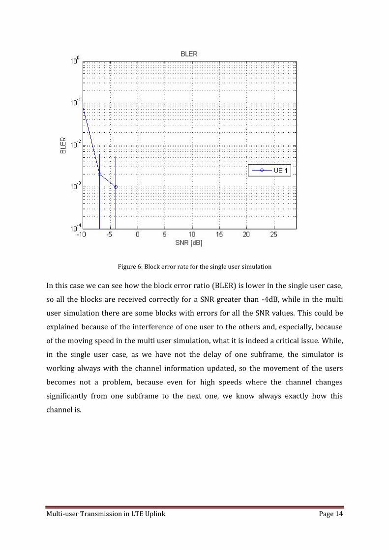
Figure 6: Block error rate for the single user simulation
In this case we can see how the block error ratio (BLER) is lower in the single user case,
so all the blocks are received correctly for a SNR greater than -4dB, while in the multi
user simulation there are some blocks with errors for all the SNR values. This could be
explained because of the interference of one user to the others and, especially, because
of the moving speed in the multi user simulation, what it is indeed a critical issue. While,
in the single user case, as we have not the delay of one subframe, the simulator is
working always with the channel information updated, so the movement of the users
becomes not a problem, because even for high speeds where the channel changes
significantly from one subframe to the next one, we know always exactly how this
channel is.

Multi-user Transmission in LTE Uplink Page 15
7. The SUS Scheduler
After the first set of simulations, new implementations are developed in order to have a
more complex and heterogeneous MU-MIMO simulator, with the goal of being capable to
do new type of simulations that brings us new fields to simulate and analyze, and
explore the big potential of this program.
The first new implementation carried out is a new scheduler, which has the goal to
improve the cell throughput, giving more resources to the users with better signal
available, instead of the currently used Round Robin, which gives all the users the same
resources no matter their conditions. With this new scheduler it is intended to maximize
the cell throughput, serving the users who are expected to have a higher throughput at
that moment. This scheduler is less fair than the round robin, but it’s better in terms of
system performance. The operation of this scheduler is based on a greedy proportional
fair scheduler who pre-selects the users using the semi-orthogonal user selection,
together with the SINR estimation in the base station and from this value the calculation
of the transmission rate for each user [5]. The selection of potential users to be
scheduled are based on an orthogonal threshold, whose value is defined in the scheduler
itself, and important to determine the optimal performance of this scheduler. For this
reason, given a concrete number of users in the system, the scheduler is run with
different orthogonal threshold values to find the optimal one. The bigger the number of
users, the lower this value is. Therefore, the scheduler is run for different number of
users (10, 20, 30, 40), and in each case the optimal value is found, that is, the one that
performs the highest cell throughput. As we have only one transmitting antenna, the
optimal value will be always between 0 and 1, and values greater than one would be
nonsense.
So from a list of all the users, the potential users to be scheduled [P] are chosen
following the algorithm of the figure below, following the next equation:
Being B = orth(Hint) , an orthonormal basis of Hint with the same matrix range, where

Multi-user Transmission in LTE Uplink Page 16
Hint = [h1, … , hs−1, hs+1, … , hS] and hs = orth(hs), being hs the channel of one of the
potential users P to be scheduled. The condition of the selection of the potential users to
be scheduled is:
𝑡𝑟 (ℎ��𝐵𝐵𝐻ℎ𝑠𝐻) ≤ αSUS ,
where all the users below this threshold are selected.
Once we have the list of potential users to be scheduled, its estimated achievable
throughput is calculated based on its SNR, taking into account it is scheduled in parallel
with the previous selected users:
𝑔𝑢 = (𝐼 − 𝐵𝐵𝐻 ) ∗ ℎ��
𝑆𝐼𝑁𝑅 = 𝑡𝑟 (ℎ𝑠 𝑔𝑢 𝑔𝑢
𝐻 ℎ𝑠𝐻)
𝜎𝑛2 ∗ 𝑡𝑟 ( 𝑔𝑢 𝑔𝑢
𝐻 )
So the estimated throughput will be:
𝑅𝑠 = 𝑙𝑜𝑔2 (1 + 𝑆𝐼𝑁𝑅)
The weighted rate of all users if computed, by dividing the estimated throughput of that
user by the average throughput of the scheduled user over the past, defined as 𝑇𝑠. The
user with the maximum weighted rate will be selected to be scheduled if the inclusion of
this user improves the average weighted throughput of the scheduler; otherwise this
user will be discarded. If the user is scheduled, the throughput achievable in the
subframe, 𝑅𝑠 , for each of the users already scheduled is calculated again, taking into
account this new user as well.
The algorithm of the scheduler is the following one:

Multi-user Transmission in LTE Uplink Page 17
Figure 7: SUS scheduler algorithm [5]
Where, in our case, as the users have only one transmitter antenna instead of multiple
ones, ℎ�� is used instead of ��𝑠.
In this case, L is set to one, so the algorithm stops when the maximum possible of users
have been served or if adding an additional user does not improve the rate anymore,
being 4 the maximum number of users, as we have four antennas in the base station.
Once the intended scheduler is working, the first simulations to evaluate its
performance are conducted, using 10 users and a set of orthogonal threshold values:

Multi-user Transmission in LTE Uplink Page 18
Figure 8: Cell throughput in the SUS scheduler for different alpha values for 10 users
Observing the graphic above, we can see how the orthogonal threshold value (alpha)
affects the operation of the scheduler. The optimal value in this case is alpha = 0.8,
having with all the values between 0.8 and 1 very similar results.
Α Average Cell throughput (Mbps)
0.4 8,6375
0.6 9,6392
0.8 10,0565
0.9 10,0491
1 10,0511
Table 1: Cell throughput for SUS scheduler with 10 users
The first results show that the new scheduler improves the cell throughput that the
Round Robin scheduler gave. However, to know how good this scheduler really is, it is
necessary to compare it with the optimal case. To make it possible, a new scheduler is
needed that gives in all the occasions the optimal scheduling in terms of cell throughput.
In order to make this possible, an exhaustive search scheduler is needed. The exhaustive
search scheduler is based on computing all the different user allocation combinations,
and the throughput obtained in each one of all the possible combinations of users, to get
the scheduling combination that gets the maximum throughput in each subcarrier of
each radio block. With this algorithm, we ensure to have always the optimal resource
allocation among the users of the system, with the important drawback that it requires a
very high computational cost, which increases exponentially with the number of users,
making it not feasible for a great number of users. For this reason, the exhaustive search
scheduler is only a scheduler designed to evaluate the performance of the other
scheduler in the simulator and see how close are from the optimal case. Due to its

Multi-user Transmission in LTE Uplink Page 19
computational and timing constraints we have in the real systems, this is nowadays
impossible to implement in a commercial network.
When the exhaustive search scheduler algorithm is implemented in the simulator, we
can check how good the greedy proportional fair scheduler really is.
Figure 9: Comparison between exhausting and SUS scheduler for 10 users
Comparing the SUS scheduler throughput for different orthogonal threshold values with
the optimal scheduling case, we can see how the greedy scheduler results are close to
the optimal one, what allows us to conclude that it is a good scheduler with a very good
performance.
In order to understand the difference among the schedulers implemented so far, and to
see also how the SUS scheduler enhances the system performance in comparison with
the fair scheduler, the cell throughput of the three schedulers is plotted. In the greedy
scheduler, the optimal threshold value is taken (alpha = 0.8).

Multi-user Transmission in LTE Uplink Page 20
Figure 10: Comparison between exhausting, Round Robin and optimal SUS scheduler for 10 users
As we can see in the simulation results, the SUS scheduler, or greedy proportional fair
scheduler, improves significantly the system performance of the fair Round Robin
scheduler, and its operation is closer to the optimal one.
Once it is known that the greedy proportional fair scheduler performance present the
expected results, it is evaluated for different number of users as well, always comparing
the results with the optimal case.
For a simulation of 20 users in the system, the results obtained are the following ones:

Multi-user Transmission in LTE Uplink Page 21
Figure 11: Cell throughput in the SUS scheduler for different alpha values for 20 users
In this case, the optimal threshold value is among 0.7 and 0.9, being 0.8 the optimal
value. The cell throughput simulation results obtained for the different orthogonal
threshold values are the next ones:
α Average Cell throughput (Mbps)
0.4 9,8513
0.5 10,4020
0.6 10,6600
0.7 10,6919
0.8 10,7032
0.9 10,6728
Table 2: Cell throughput for SUS scheduler with 20 users

Multi-user Transmission in LTE Uplink Page 22
In this case, as we have 20 users instead of 10, the possibilities to find users that are
more orthogonal among them are greater, what in terms of results means an
enhancement of the cell throughput for all the alpha values, in comparison with the
simulation of the greedy scheduler for only 10 users.
If we compare these results with the optimal case, given by the exhaustive search
schedule, we can see how the results are again close to the optimal case, which means
that the scheduler works properly for different number of users.
Figure 12: Comparison between exhausting and SUS scheduler for 20 users
For 30 users, the cell throughput increases again with respect to the previous cases, as
we can see in the following figure:

Multi-user Transmission in LTE Uplink Page 23
Figure 13: Cell throughput in the SUS scheduler for different alpha values for 30 users
In this case, the optimal threshold value is between 0.6 and 0.9, being 0.6 the optimal
value, which is lower than in the last simulation for 20 users. As it should be, the optimal
threshold value decreases slowly when we increase the number of users, because as we
have a great number of potential users to schedule, we do not need a big alpha value to
already include a big amount of users who are candidate to be allocated. The cell
throughput results obtained for the different orthogonal threshold values in this
simulation are the next ones:
α Average Cell throughput (Mbps)
0.4 10,4671
0.5 10,8812
0.6 10,9533
0.7 10,9445
0.8 10,9481
0.9 10,9422
Table 3: Cell throughput for SUS scheduler with 30 users
Comparing the results with the optimal case, as was expected, the performance of the
system is close to the optimal one:

Multi-user Transmission in LTE Uplink Page 24
Figure 14: Comparison between exhausting and SUS scheduler for 30 users
Simulating the greedy scheduler for 40 users, the simulation results are the following
ones:
Figure 15: Cell throughput in the SUS scheduler for different alpha values for 40 users

Multi-user Transmission in LTE Uplink Page 25
Now, the optimal threshold value is among 0.5 and 0.7, being 0.6 the optimal value,
which is again lower than in the previous simulations. The cell throughput results
obtained for the different orthogonal threshold values in the SUS scheduler simulation
for forty users are the next ones:
α Average Cell throughput (Mbps)
0.4 10,8742
0.5 11,1178
0.6 11,1360
0.7 11,1145
0.8 11,1061
0.9 11,1178
Table 4: Cell throughput for SUS scheduler with 40 users
In this case, and for 50 users as well, due to the computational constraints we have
because of the complexity of the exhaustive search scheduler, the SUS results are not
compared with the optimal scheduler ones. The computational time requested to carry
out the exhaustive scheduler simulation would be too much large, and having the
comparison results obtained previously for 10 20 and 30 users, we can extrapolate that
for 40 and 50 users the SUS results will be also close to the optimal scheduling
performance.
In the same way, running the simulator for 50 users, we obtain in this case the following
results:

Multi-user Transmission in LTE Uplink Page 26
Figure 16: Cell throughput in the SUS scheduler for different alpha values for 50 users
Now, the optimal threshold value is among 0.5 and 0.6, being 0.6 the optimal value. In
these simulations, the cell throughput results obtained for the different orthogonal
threshold values in the greedy scheduler simulation for the fifty users are the next ones:
α Average Cell throughput (Mbps)
0.4 11,0613
0.5 11,2128
0.6 11,2132
0.7 11,2070
0.8 11,2069
0.9 11,1872
Table 5: Cell throughput for SUS scheduler with 50 users
If we compare the different simulations of the SUS scheduler for the different number of
users, we can see how the optimal threshold values decreases and the cell throughput
increases. However, as we increase the number of users, the difference with the

Multi-user Transmission in LTE Uplink Page 27
previous simulation is lower than the previous case. That is, the throughput differences
between the simulations of forty and fifty users for the SUS scheduler shown above are
much lower than the differences between the simulations of 10 and 20 users.

Multi-user Transmission in LTE Uplink Page 28
8. The MMSE filter
After finishing the scheduler implementation and verification, the next implementation
is a new detector based on MMSE (minimum mean square error) [6] [7], instead of the
zero forcing used hitherto. This new receiver should have a better performance in the
simulations, especially when the channel is not perfectly known, which is a most reliable
simulation in terms of similarity to the real life. With an imperfect channel estimator,
using the zero forcing the interference will not be completely eliminated anymore. In
this case, it is expected that the MMSE will present better results than the zero forcing
detector, using a suboptimal filter in the receiver, by minimizing the error between the
real signal and the estimated one: WMMSE = min(E‖x − x‖2) .
The signal used so far, without considering channel estimation error is:
x𝑢 = guH ∗ hu ∗ xu + gu
H ∑ hj ∗ xjj≠u + guH ∗ n
To work in the realistic case, where the channel is not perfectly known, we introduce an error in
the channel of the simulator, to carry out some simulations with this fact and understand how
this problem affects to the performance of the system. This channel estimation error is defined
as:
hu = hu + eu , where eu~N(0, σe2) defines the error
Taking into account the error described above, we have the following signal:
x𝑢 = guH ∗ hu ∗ xu + gu
H ∑ hj ∗ xjj≠u + guH ∗ eu ∗ xu + gu
H ∑ ej ∗ xjj≠u + guH ∗ n
being gu the optimal MMSE receiving filter, the optimal solution is obtained as:
gu = (∑ hjUj≠u ∗ hj
H + (σn2 + σe
2 ∗ nUE) ∗ I)−1
∗ hu

Multi-user Transmission in LTE Uplink Page 29
As a new filter has been implemented, the SNR calculation changes as well. Therefore, a
new SINR equation is established for this receiver, in order to work correctly with the
CQI adaptation in the schedulers:
𝑆𝐼𝑁𝑅 = ‖ gu hU‖
2
𝜎𝑛2 ∗ ‖ gu ‖
2+ ‖gu ∗ 𝐻𝑖𝑛𝑡‖
2
When the MMSE filter is implemented, it is compared with the previous zero forcing
receiver, to compare both results and check that the new one improves the system
performance.
To see how the new MMSE filter performs in comparison to the ZF filter, we can do a
simulation in the same conditions for both filters and observe both cell throughput
figures. If the MMSE improves the zero forcing receiver as expected, the cell throughput
should be higher in the MMSE case than in the ZF one.
Figure 17: Comparison between ZF and MMSE
Multi-user Transmission in LTE Uplink Page 30
As we can see in the figure above, as was expected, the MMSE receiver improves the
previous ZF one, especially in low SNR values. As the MMSE filter includes the noise
variance in its equation, it becomes more robust to cope against the noise. Therefore, the
performance of the MMSE filter brings us a higher cell throughput, succeeding with the
target of improving the first implemented receiver.
The MMSE receiver has been implemented not only to have a better performance in this
last case, but to be able in the simulator to cope with the channel estimation error. In the
simulations carried out so far, perfect channel knowledge was supposed. However, in
the reality, the channel is not perfectly known, and the estimations are not perfect.
Because of this, the receivers are not able to cancel the interference of the other users
completely. In the simulator, an intended error is added to the channel to simulate the
real case where the estimated channel is not the same than the actual one, but a little
different. This error is defined by its variance, defined as σe2, which adds a random error
value to each value of the channel.
In this new case, the MMSE receiver is intended to minimize the error that this error
estimation causes in the receiver, so the loss of performance is minimized. Compared
with the zero forcing filter, it should make an important difference in terms of
throughput and error, performing a better reception of the signal.
To see how both receivers behave, we compare them along different channel estimation
error values. With these simulations, besides comparing both filters, it is intended to see
how the estimation error affects the system performance as well. The simulations are
carried out using the Round Robin scheduler, due to its lower complexity and that it has
been already frequently used, so it is easier to see the changes regarding the channel
estimation error in comparison to the previous simulations without that error.

Multi-user Transmission in LTE Uplink Page 31
For a σe2 = 0.001:
Figure 18: Comparison between ZF and MMSE for a 0.1% of channel estimation error
For a σe2 = 0.01:
Figure 19: Comparison between ZF and MMSE for a 1% of channel estimation error

Multi-user Transmission in LTE Uplink Page 32
For a σe2 = 0.1:
Figure 20: Comparison between ZF and MMSE for a 10% of channel estimation error
Beholding the previous figures we can stand out two main facts. The first one is that we
can see how the channel estimation error affects in the performance of the simulation.
Small error values have already a big impact in the throughput of the cell. For an error of
1%, this throughput is reduced to the half in comparison to the perfect channel
knowledge; with a 10% error, it is decreased to the fourth part with the MMSE filter and
to the eighth part with the zero forcing filter.
The second conclusion we can take is how the MMSE filter outperforms the previous
zero forcing filter. As we saw in the first comparison between both receivers without
error, the MMSE enhanced the results especially in small SNR values, so in the worst
condition signal. With the estimation error, the MMSE improves the results more
significantly, being its effect bigger when the channel estimation error grows, even
doubling the cell throughput of the ZF filter in the 10% error case.
Multi-user Transmission in LTE Uplink Page 33
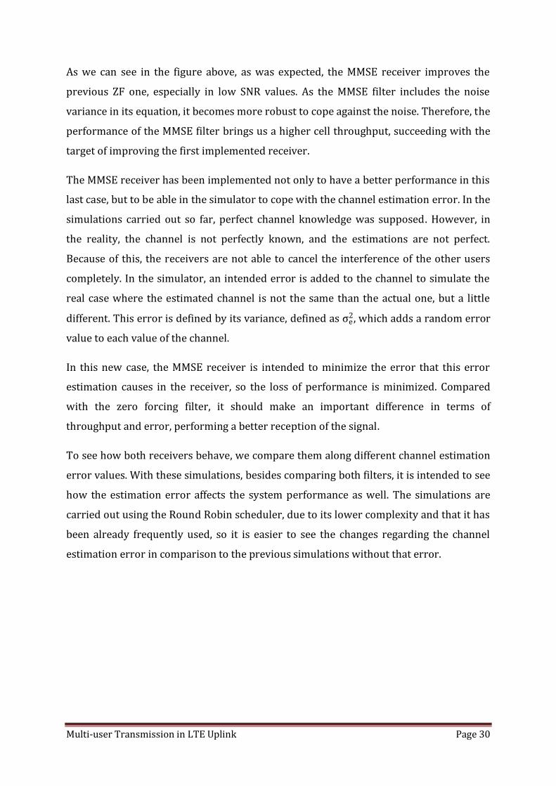
To have more information about the difference between both receivers, we can see in
the following figures how the bit error rate (BER) and the cell throughput changes along
different channel error in both receivers, for different CQI values. The continuous curves
belong to MMSE, the dashed to ZF; the blue stand for channel estimation error of 0.001,
the red for =.01 and the green for an error of 0.1:
CQI=4, BER
Figure 21: BER comparison between ZF and MMSE for CQI=4 and different channel estimation errors

Multi-user Transmission in LTE Uplink Page 34
CQI=4, cell throughput
Figure 22: Throughput comparison between ZF and MMSE for CQI=4 and different channel errors
CQI=8, BER
Figure 23: BER comparison between ZF and MMSE for CQI=8 and different channel estimation errors

Multi-user Transmission in LTE Uplink Page 35
CQI=8, cell throughput
Figure 24: Throughput comparison between ZF and MMSE for CQI=8 and different channel errors
CQI=10, BER
Figure 25: BER comparison between ZF and MMSE for CQI=10 and different channel estimation errors

Multi-user Transmission in LTE Uplink Page 36
CQI=10, cell throughput
Figure 26: Throughput comparison between ZF and MMSE for CQI=10 and different channel errors
As we can see in these plots, the MMSE filter improves, as seen also in the first figures,
the ZF receiver, especially with high channel estimation error. We can understand
beholding these figures how the channel estimation error penalizes the throughput of
the system as well, and how important is to select the optimal CQI value, because as we
can see in last figure, a very high CQI value for big channel estimation errors makes the
system not working properly anymore.
After the confirmation that the MMSE filters achieves the expected results, we can
simulate both receivers for the link adaptation case as well, where the CQI varies
regarding the SNR of the user, which is more accurate to the reality. As can be observed
in the following tables, the MMSE presents better results, both in terms of throughput
and BER.

Multi-user Transmission in LTE Uplink Page 37
Channel error estimation
BER Cell throughput
0 0.1066 8.3822
0.001 0.1044 7.4594
0.005 0.1151 6.2476
0.01 0.1219 5.4413
0.05 0.1504 3.6995
0.1 0.1608 2.8133
0.2 0.1784 1.8219 Table 6: BER for MMSE receiver with CQI adaptation for different channel estimation errors
Channel error estimation
BER Cell throughput
0 0.1394 7.3382
0.001 0.1455 6.7696
0.005 0.1603 5.2557
0.01 0.1731 4.2091
0.05 0.2288 1.6306
0.1 0.2757 0.7892
0.2 0.3324 0.2823 Table 7: BER for ZF receiver with CQI adaptation for different channel estimation errors
After all this simulations results it is concluded that the MMSE filter has an important
gain against the old zero forcing filter, so the target of implementing a new better
receiver is achieved with success.
To try to reduce the bit error rate for the CQI adaptation case, it is implemented a new
method to get the CQI values. This new implementation is based on a more restricting
way to compute the most accurate CQI value in each subframe for each user, where
instead of average the different SNR values computed in the scheduler for each resource
block, the value taken is the minimum of all this values. With this idea it is intended to
have the same or lower CQI values than without this SNR restriction, which should
reduce the BER, with the penalization of reducing the cell throughput as well.

Multi-user Transmission in LTE Uplink Page 38
After implementing this new method in the system, we make the simulations using
round robin scheduler and error over subcarriers, so we can compare the results with
the previous simulations results shown in table [13] [14], which have been carried out
with the same setting parameters with the exception of the SNR restriction in this case.
Channel error estimation
BER Cell throughput
0 0.0099 7.9534
0.001 0.1020 7.1523
0.005 0.1078 5.5888
0.01 0.1106 4.7534
0.05 0.1196 2.9914
0.1 0.1297 2.3495
0.2 0.1501 1.8036 Table 8: Cell throughput and BER in MMSE receiver for error over subcarriers method with CQI
adaptation and minimum SNR value implementation
Channel error estimation
BER Cell throughput
0 0.1393 7.3379
0.001 0.1421 6.3564
0.005 0.1511 4.5286
0.01 0.1598 3.4985
0.05 0.2183 1.3032
0.1 0.2683 0.6280
0.2 0.3305 0.2803 Table 9: Cell throughput and BER in ZF receiver for error over subcarriers method with CQI adaptation
and minimum SNR value implementation
After these simulations, we can see how the BER has slightly decreased for both
receivers and different channel error estimation. However, the loss of throughput
becomes more significant than the gain in the bit error ratio. For this reason this new
implementation is dismissed, and the simulator is set up again with the older average
SNR implementation.

Multi-user Transmission in LTE Uplink Page 39
Once all this simulations are finished, we establish the error over resource blocks as the
optimal way to introduce the channel error estimation, agreeing with the outperforming
of this way against the other proposals. Therefore, the simulator is set up with this
implementation and all the following simulations are carried out with this characteristic.
After finishing the channel estimation error simulations and getting the optimal
configuration to implement it, we make the same simulations for the SUS scheduler, to
see how this scheduler copes against the channel estimation error. As it has been done
before in the first simulations of the SUS scheduler to evaluate its performance, the
results obtained are compared again with the optimal scheduling, that is, with the
simulation results of the exhaustive search scheduler.
MMSE receiver:
Channel error estimation
BER Cell throughput
0 0.0423 8.1668
0.001 0.0433 7.9775
0.005 0.0476 7.2034
0.01 0.0515 6.4619
0.02 0.0562 5.5451
0.05 0.0622 4.3149
0.1 0.0657 3.4830
0.2 0.0735 2.6181
Table 10: Cell throughput and BER in MMSE receiver with SUS scheduler for link adaptation and alpha=0.8

Multi-user Transmission in LTE Uplink Page 40
ZF case:
Channel error estimation
BER Cell throughput
0 0.0496 7.9246
0.001 0.0505 7.7794
0.005 0.0551 6.9480
0.01 0.0595 6.1242
0.02 0.0648 5.1219
0.05 0.0721 3.7088
0.1 0.0796 2.6499
0.2 0.0997 1.6334
Table 11: Cell throughput and BER in ZF receiver with SUS scheduler for link adaptation and alpha=0.8
As it should be, the performance of the SUS scheduler improves significantly the Round
Robin simulation results. In this case, as we have only 4 users, the SUS scheduler
function is decide is the four users all allocated (we have 4 different layers), or some
users are not allocated and some layers are not used. Although could seem strange that a
layer empty is better than having an user with bad signal conditions, if we think in terms
of cell behavior, the interference caused by this user with a bad SNR to the other users
causes a bigger loss of throughput than the one he would get. This allows reducing the
average BER of the cell for the different users in comparison to the Round Robin
scheduler, also increasing slightly the throughput, especially in the worst conditions,
with low SNR value and high channel estimation error.
As the number of users we have in this simulation is lower than in the first SUS
scheduler simulation when it was implemented, when the lowest number of user was
10, with an orthogonal threshold of alpha = 0.8, we try to repeat the same simulations
with an alpha value of 0.9, which could be the optimal threshold value in this case. As the
factor is bigger, the scheduler will be less restrictive when deciding which users are
scheduled, so the BER could increase respect the last simulation where the orthogonal
threshold value was 0.8. The throughput, however, may be increased, because as the
admission restrictions are lower there will be more users scheduled in some cases.

Multi-user Transmission in LTE Uplink Page 41
The simulation results for alpha =0.9 are the following ones:
MMSE receiver:
Channel error estimation
BER Cell throughput
0 0.0443 8.2735
0.001 0.0456 8.0648
0.005 0.0504 7.1047
0.01 0.0547 6.3047
0.02 0.0587 5.3897
0.05 0.0637 4.2066
0.1 0.0678 3.3555
0.2 0.0762 2.5293 Table 12: Cell throughput and BER in MMSE receiver with SUS scheduler for link adaptation and alpha=0.9
ZF case:
Channel error estimation
BER Cell throughput
0 0.0535 8.0122
0.001 0.0548 7.7778
0.005 0.0604 6.7611
0.01 0.0647 5.8817
0.02 0.0696 4.7945
0.05 0.0772 3.3200
0.1 0.0901 2.2561
0.2 0.1113 1.3630
Table 13: Cell throughput and BER in ZF receiver with SUS scheduler for link adaptation and alpha=0.8
Observing the tables above, we can see how the BER increases respect the SUS
simulations with alpha=0.8. AS more users are scheduled, the BER probability increases,
that makes this value increase. This effect becomes more important in the ZF receiver,
because, as it has been seen before as well, this receiver is less effective to cope against
errors and signals with low SNR values, while the MMSE is a more robust receiver. In the
case of the cell throughput, we have the same results for both receivers: with low

Multi-user Transmission in LTE Uplink Page 42
channel estimation errors, the less restrictive scheduler achieves higher throughput
results, while when the error becomes more important, the most restrictive one
presents a better behavior, due to the tougher admission control it has, which allows
having less interference in the cell, that for high channel estimation errors makes easier
the detection and therefore achieves higher throughput values.
To finish with this chapter, one more simulation is carried out. In this case, the number
of users is increased to 30, and the optimal threshold value is taken of the simulation
done previously for the SUS scheduler for 30 users. From table [3], we set up the alpha
value to 0.6. In this simulation, as the scheduler is able to get the users with best
condition signal among a big number, the users chosen in all cases should present good
SNR values in all cases. Therefore, besides of an important increase of the cell
throughput, the BER should be significantly decreased, presenting much better
simulation results than for only 4 users in the system.
MMSE receiver:
Channel error estimation
BER Cell throughput
0 0.0319 10.6353
0.001 0.0322 10.5798
0.005 0.0340 10.2624
0.01 0.0379 9.5256
0.02 0.0449 8.1864
0.05 0.0568 6.2163
0.1 0.0596 4.9161
0.2 0.0647 3.6820 Table 14: Cell throughput and BER in MMSE receiver with SUS scheduler for 30 users for link adaptation
and alpha=0.6

Multi-user Transmission in LTE Uplink Page 43
ZF case:
Channel error estimation
BER Cell throughput
0 0.0351 10.5207
0.001 0.0353 10.4702
0.005 0.0370 10.1673
0.01 0.0397 9.5059
0.02 0.0452 8.2503
0.05 0.0547 6.2593
0.1 0.0543 4.8332
0.2 0.0633 3.3391 Table 15: Cell throughput and BER in ZF receiver with SUS scheduler for 30 users for link adaptation and
alpha=0.6
As we expected, both BER and cell throughput are clearly improved respect the four
users case. The SUS scheduler, as it was concluded when this scheduler was evaluated,
improves its performance when there are in the cell a significant number of users. In
that case, the scheduler is able to select always the users with best signal conditions and
therefore get higher throughput values while enabling low bit error rate results.
To validate the SUS scheduler simulation results, we compare them with the exhaustive
search scheduler, that is, with the optimal case. Based on the previous scheduler
comparison, where the exhaustive scheduler was used to evaluate the SUS scheduler, the
performance of the SUS scheduler should not be very far of the optimal case. To make
the comparison, we carry out the same simulations done for the SUS scheduler, for four
users in the cell and for different channel estimation errors:

Multi-user Transmission in LTE Uplink Page 44
MMSE receiver:
Channel error estimation
BER Cell throughput
0 0.0431 8.4670
0.001 0.0438 8.1657
0.005 0.0473 7.2908
0.01 0.0506 6.6049
0.02 0.0545 5.7771
0.05 0.0616 4.6277
0.1 0.0660 3.7965
0.2 0.0726 2.9741 Table 16: Cell throughput and BER in MMSE receiver with exhaustive search scheduler for link adaptation
ZF receiver:
Channel error estimation
BER Cell throughput
0 0.0401 8.3607
0.001 0.0409 8.0286
0.005 0.0477 7.1588
0.01 0.0476 6.4337
0.02 0.0525 5.5492
0.05 0.0594 4.3214
0.1 0.0636 3.4244
0.2 0.0713 2.4674 Table 17: Cell throughput and BER in ZF receiver with exhaustive search scheduler for link adaptation
Comparing these results with the SUS scheduler results for both alpha values, so tables
[19],[20],[21],[22], we can observe how, indeed, the exhaustive scheduler results are
better, being the optimal results, but the SUS scheduler performance is, as we saw in the
first simulations for the schedulers without channel estimation errors, not far from
them, proving again the good behavior of this scheduler.

Multi-user Transmission in LTE Uplink Page 45
Once all these simulations are finished, we conclude the MMSE receiver part with
satisfactory results. A new filter has been implemented with success, which is capable to
work in bad signal conditions and get still good results, outperforming the previous zero
forcing filter in all the simulations that has been carried out, making specially the
difference in high channel estimation errors, reducing significantly the bit error rates
and improving the cell throughput of the system.
Now, the multi-user MIMO simulator is capable to make the simulations using different
schedulers, different receivers and with the chance of introducing a channel estimation
error to try to be as close as possible to the real case, which is obviously the willing of
any simulator.
The last implementation in the simulator is a new receiver, based on MMSE, called SIC,
successive interference cancellation, which target is improving the current MMSE
receiver using this technique, which consist in remove the interference signal of one
user from the users detected previously.

Multi-user Transmission in LTE Uplink Page 46
9. Successive interference cancellation (SIC)
Figure 27: Successive interference cancellation for two users
Successive interference cancellation is a technique used in MU-MIMO systems, which is
based on eliminating the interference signal of other users while the user is being
detected, by storing the detected signals of the previous users already detected in the
system and subtracting it from the current user [8]. As we can see in the figure above,
once one user is decoded, its signal is sent to the receiver of the following user, which
eliminates that interference signal of the first user from its signal, reducing therefore the
total interference perceived by that user and consequently improving the SINR of the
user and therefore reducing the bit error probability.
To implement this, in the detection function, every detected signal of each user is stored
and when the next user is detected, from its signal the previous user signal is subtracted.
In this case, as the users are always detected in the same order, user 1 has the same
results as with the normal MMSE receiver, since no interference signal is cancelled for it.
But for the following users, the results should be better than in the previous simulations
with the normal MMSE receiver, being successively more improved in each user. That is,
for the second user, only the interference signal of the first user is cancelled, so it should
experiment a slight gain. However, for the last user, as all the other users have been
already detected, the improvement should be much greater, because all the interference
of other users are being subtracted, and in the ideal case with no detection errors that
last user signal should have no interference on it.

Multi-user Transmission in LTE Uplink Page 47
Having the following signal in the receiver:
𝑦 = ℎ1 ∗ 𝑥1 + ℎ2 ∗ 𝑥2 + … + ℎ𝑈 ∗ 𝑥𝑈 + 𝑛𝑘 = ∑ ℎ𝑖 ∗ 𝑥𝑖 + 𝑛𝑘
𝑈
𝑖=1
For the user n, the signal after the SIC receiver of this user is:
𝑦�� = ℎ1 ∗ 𝑥1 + ℎ2 ∗ 𝑥2 + ⋯ + ℎ𝑛−1 ∗ 𝑥𝑛−1 + ℎ𝑛 ∗ 𝑥𝑛 + ℎ𝑛+1 ∗ 𝑥𝑛+1 + ⋯
+ ℎ𝑈 ∗ 𝑥𝑈 + 𝑛𝑘 − ℎ1 ∗ ��1 − ℎ2 ∗ ��2 − ⋯ − ℎ𝑛−1 ∗ ��𝑛−1
All the signal of the previous users of n is subtracted from the signal of the user n,
eliminating therefore the interference in the perfect case. However, in the real case, as
the signal detected of the previous users is not exactly the same as the signal that was
sent from those users, due to detection errors, the interference of the previous users is
not completely eliminated and there is still a residual value of it.
However, as we are not in the perfect case, we have also the problem that as we are
combining signals of different users to eliminate the interference, the errors in the
detection are being propagated from one user to the other, so we need to take into
account that for high BER the SIC MMSE receiver could even perform worse results than
the normal MMSE receiver
To start implementing the SIC receiver, the signal of the detected user is detected and
stored. This signal consists of the estimated signal of the QAM constellation from the
signal at the output of the filter multiplied by the channel of the own user. To make the
simulations, the channel estimation error is set to 0 to avoid excessive error propagation
and to see if there is really an improvement of the signal and therefore of the BER of the
users when they are detected. Once the SIC receiver is working properly, the simulation
are carried out.
However, as the propagation error is not known, the SINR estimate used for
adaptation is actually not really appropriate for the SIC, since it assumes MMSE
receivers. As the problem is that we cannot have a better estimate that accounts for
error propagation, the SIC simulations are carried out to see the BER in different
situations, which will provide the information needed to see if the SIC receiver is

Multi-user Transmission in LTE Uplink Page 48
working properly and then check that effectively there is a gain in the bit error rate
respect the normal MMSE receiver.
First of all, we simulate the SIC receiver for fixed CQI values, expecting to see how the
BER changes along the different users for the same simulation conditions:
For CQI=1, which supposes QAM modulation:
Figure 28: BER for hard SIC for CQI=1
For CQI=15, what means 64QAM:

Multi-user Transmission in LTE Uplink Page 49
Figure 29: BER for hard SIC for CQI=15
To compare the BER properly and to ensure correct operation of the MMSE-SIC receiver,
the simulations with fixed CQI are compared, to see how the BER changes. The extreme
CQI values for each modulation are taken and compared between them.
For QAM modulation, the CQI values 1 and 6 are simulated obtaining the following
results, being CQI=1 the continuous lines and CQI=6 the dashed, both with 4QAM
modulation:

Multi-user Transmission in LTE Uplink Page 50
Figure 30: BER comparison for new SIC for CQI=1 and CQI=6
For the 16QAM, CQI values 7 and 9, being CQI=7 the continuous lines and CQI=9 the
dashed:
Figure 31: BER comparison for hard SIC for CQI=7 and CQI=9

Multi-user Transmission in LTE Uplink Page 51
And for the best modulation available in the simulator, 64 QAM, the CQI values are set
up to 10 and 15 respectively, being CQI=10 the continuous lines and CQI=15 the dashed:
Figure 32: BER comparison for hard SIC for CQI=10 and CQI=15
As we can see in the CQI comparison figures, there is no difference between the BER of
each pair of CQI values. As we have a hard detection SIC, where the data of the previous
users is taken directly after the MMSE receiver, so we do not have any coding gain, we
do not see any difference in the BER curves of the users.
Simulating with CQI adaptation:
Once we have seen the gain of the SIC receiver with fixed CQI values, we simulate with
CQI adaptation to see how the system behaves in this case. However, as it has
been not possible to implement a SINR equation to compute the corresponding
CQI value taking into account the error propagation, this SINR value is based on
the previous MMSE filter equation. For this reason, there is not any throughput

Multi-user Transmission in LTE Uplink Page 52
gain between the MMSE and the MMSE-SIC filters. At any rate, this SINR approach
should work if the propagation error is not very big.
Figure 33: BER comparison for hard SIC for CQI adaptation
In this case, we can see how the BER has a little gain from the first user to the others for
high NSR values. However, from the second user to the last any important BER gain is
seen. With the hard decision SIC and link adaptation, the propagation error becomes an
important fact, what makes that the expected gain in the bit error rate of the users is
almost unappreciable.
This implementation, however, is not fair, because one user gets always the best results
and other user interference is never cancelled. For this reason, a new version of the SIC
MMSE receiver is developed. In this case, instead of having always the same order of the
users in the detector, this order is chosen regarding their SNR value. With this new
implementation two aspects are being improved. The first one is the fairness issue. Now
on average all the users should get the same gain from the interference cancellation. And
the most important improvement is that now, the user with best SNR is the first being

Multi-user Transmission in LTE Uplink Page 53
detected and the user with worst signal is the last. This means two things: first, the user
with better signal, the one who should need less its interference to be cancelled, is the
first one detected, while the user with worst SNR is the one that gets more gain of the
SIC, so from its signal is being subtracted all the interference from the other users; the
second important gain is that as the users with best signals are the firsts to be detected,
the propagation of the error decreases significantly with respect to the case with no
ordering of users.
When we make the simulations for the SIC with the optimal order, we do not see any
more a difference between the BER for the different users, so on average all should be
the same because of the changing order in the detector. But if we observe the global
performance of the system, we can see that is a gain in the performance, with better
BLER and throughput.
To reduce the error propagation, a new way to implement the SIC is proposed. In this
case, instead of get directly the signal of the user from the detector, this signal is first
being again encoded in the receiver function like it is done in the transmitter when the
signal is sent, so that errors should disappear. In this new case, the SIC MMSE receiver
should improve its performance, especially in the worst cases, where the propagation of
the detection errors becomes more important.
After the implementation of this part, we repeat the simulations done for the first
successive interference cancelation receiver, using the same fixed CQI values.
Multi-user Transmission in LTE Uplink Page 54
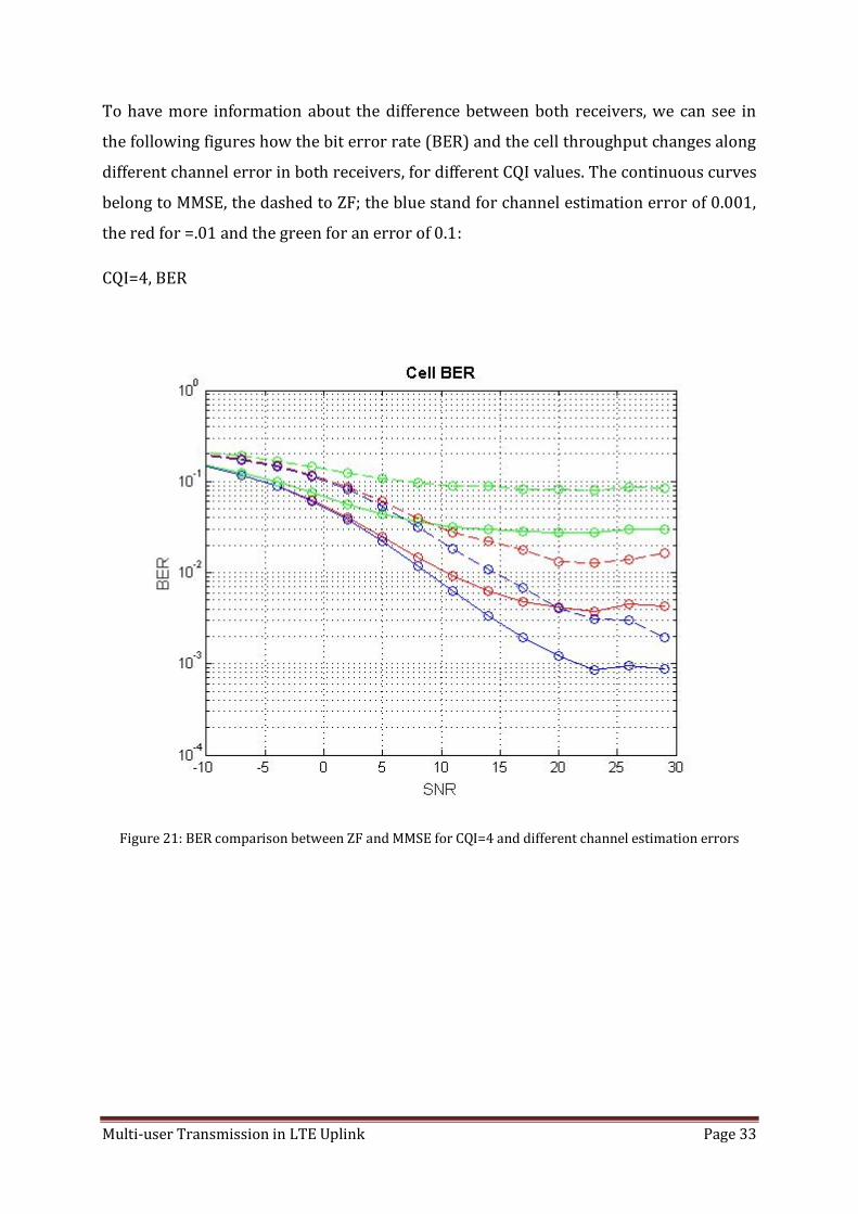
For the CQI values 1 and 6 case, being the continuous lines the BER for CQI=1 and the
dashed for CQI=6:
Figure 34: BER comparison for new SIC for CQI=1 and CQI=6
In this case, if we compare the figure with the same simulation with hard decision SIC
(figure xx), we can observe an important difference between CQI 1 and CQI 6. As CQI 1
implies more redundancy and code correction than CQI 6, when the data of the user is
decoded and encoded again, this code gain becomes more important for the lowest CQI
value, so the BER reduction is much more significant.
For CQI 7 and 9, being CQI=7 the continuous lines and CQI=9 the dashed:

Multi-user Transmission in LTE Uplink Page 55
Figure 35: BER comparison for new SIC for CQI=7 and CQI=9
For the same reason as the previous figure with CQI 1 and 6, the bit error rate is lower
for the CQI 7, as we have again more coding gain.
And for CQI values of 10 and 15, being CQI=10 the continuous lines and CQI=15 the
dashed:

Multi-user Transmission in LTE Uplink Page 56
Figure 36: BER comparison for new SIC for CQI=10 and CQI=15
In all these cases, with soft decision SIC, as after the MMSE receiver we decode and
afterwards encode the data of the previous users, we can appreciate a notable difference
between the BER curves for each pair of CQI values, where the lowest CQI has always
logically a lower bit error ratio.
For CQI adaptation:

Multi-user Transmission in LTE Uplink Page 57
Figure 37: BER comparison for SIC weak without order
As in the hard decision CQI, as the SINR calculation is based on the MMSE filter, the
throughput gain is null. However, we can clearly appreciate in this figure the correct
performance of the soft decision SIC. First, we can see how there is a continuous gain
from one user to the next one, so more interference is cancelled. Moreover, comparing
this figure with the CQI adaptation for the hard decision SIC, we can see how important
is the gain achieved by decoding and encoding the data again.
Finally, to see in the same figure the difference between the two versions and confirm
the improvement in the last SIC implementation, we make the same simulation for both
cases, setting the CQI value fixed to 1.
The simulation results obtained are, being the old version the dashed curves and the
continuous curves the new one:

Multi-user Transmission in LTE Uplink Page 58
Figure 38: Comparison between SIC versions for CQI=1
Observing this figure we can understand the gain of the soft decision SIC against the
hard decision one, and the improvements of decoding and encoding the data of the
previous users. The BER curves for the soft decision SIC show better results than all the
hard decision curves, logically except for the first user, whose interference is never
cancelled, and therefore the result is the same in both cases. We can appreciate in this
image the progressive gain in the BER in the respective users as well, in the same way
we have seen in the previous figures.

Multi-user Transmission in LTE Uplink Page 59
10. Conclusions
Once all the implementations are working and all the simulations are carried out, we can
take a global look on the work to see all the proposals that have been achieved and the
results obtained, and discuss about the importance and the impact they may have
regarding MU-MIMO implementation and its feasibility on the mobile communication
networks.
Regarding the first part of the work, MU-MIMO access to a mobile communication
network improves the current single user model. By having some parallel users served
at the same time, we are able to enhance the performance of the cell up to almost the
number of users that are being served in parallel times, although for a single user there
is also a gain in the MIMO thanks to the multiplexing. While the throughput of one single
user is hardly affected if he is being served in the same time and frequency with other
users, which is very important because the user should not be able to appreciate the
difference, the cell throughput is increased substantially.
Although there will be always a slight loss of performance per user if there are other
users being served in parallel, with the current processing techniques the increase of
interference and the detection errors caused by this reason are not a critical issue, so the
system can cope with it successfully. Therefore, the loss of throughput, what is in the
end the important thing for the user, is almost impossible to appreciate.
For those reasons MU-MIMO is a very promising enhancement that could be the main
feature of the future mobile communication networks, which are already efficient and
exploiting their resources at the maximum, although they are always trying to enhance
the current systems and improve the spectral efficiency, so the bandwidth available is
always a very restrictive constraint. With the multi user access the jump of quality and
progress needed for the future networks could be done.
After the first simulations carried out, the extensions of the MU-MIMO simulator, a new
scheduler and new receivers are evaluated. The main goal is, as have been mentioned

Multi-user Transmission in LTE Uplink Page 60
above, to take the maximum profit of the advantages of the MU-MIMO and explode its
qualities.
The SUS scheduler has been intended to be implemented to improve the first scheduler
tested, the Round Robin scheduler. The main idea of the semi-orthogonal user selection
has been to schedule the users in a more efficient way than the Round Robin scheduler,
taking into account the SINR of the different users to select in all the cases the users with
best signal conditions.
This new scheduler has outperformed significantly the Round Robin one, which is only
based on serving the same amount of resources to all the users; useful to carry out some
simulations, but extremely inefficient for a real mobile communication network
implementation. The SUS scheduler results have shown that this scheduler works
properly and in an efficient way, so its feasibility to be implemented and deployed in a
commercial working mobile network is possible, of course conducting the required
changes to adapt its algorithm to the commercial case.
One of the main advantages of this scheduler is the flexibility it has thanks to the
orthogonal threshold value. This parameter could be used in a base station as an
admission control parameter, setting up a small (more restrictive) value for crowded
zones with many users in the cell area, or with a higher value for less inhabited zones.
The good performance of the SUS scheduled has been proved by the implementation of
the exhaustive search scheduler. This scheduler, not feasible in a real network for
computational constraints, can be very useful for academic and investigation purposes,
with simulations with a small number of users, because it always provides the best
possible solution. This information is very useful for comparisons with the schedulers
that are being implemented with the target that they may work in a real system. In our
case, the SUS scheduled has been always close to the optimal scheduling scenario, in all
the comparisons that have been made between it and the exhaustive scheduler, for all
the tested number of users. These comparison results have been the key factor to see
and understand the success of the SUS scheduled implemented.

Multi-user Transmission in LTE Uplink Page 61
The MMSE filter has been implemented when the channel estimation error has been
defined. The main target of this receiver has been to have a better filter than the zero
forcing filter already implemented to cope with these errors.
This new filter, which tries to reduce the interference the maximum possible while it
tries to avoid the increment of the noise, have outperformed clearly the zero forcing
filter, which does not take the noise into account.
With no noise, the MMSE filter has improved the ZF for the low SNR values. But with the
channel estimation errors, the MMSE receiver has made the big difference. This filter has
been implemented precisely to be used with the new feature of the simulator of
including errors in the channels of the users. Aiming to have a realistic simulator which
results can have a practical use, having a perfect knowledge of the channel was not a
realistic approach.
Many simulations have been carried out regarding this part. The results can be
summarized in two parts. First of all, the MMSE filter has been implemented with
success, outperforming the zero forcing filter. For this reason, the MMSE receiver is
more interesting and useful for new simulations, because its better performance allows
the simulator to obtain better results when other features are tested. In a real mobile
communication receiver, an MMSE filter makes much more sense than the ZF as well,
since the operation conditions are closer to these simulations, with channel estimation
errors and interference.
The second main conclusion that can be taken is the importance of the channel
estimation errors. A small error has already a huge impact on the performance of the
system. For this reason, it is easy to understand the importance of the channel coding
and the feedback, because improving the estimation of the channel means enhancing the
operation of the whole system.
The final main implementation of the uplink MU-MIMO simulator has been the SIC-
MMSE receiver. While the ZF and MMSE filters are already completely used and studied,
successive interference cancellation is more a new feature to be studied as a possible
implementation for new releases. SIC makes sense for MU-MIMO scenarios, where

Multi-user Transmission in LTE Uplink Page 62
several users are allocated in parallel. In this situation, the interference among them is
an important constraint, and being able to reduce it would suppose a big gain in the
system performance.
The SIC receiver has been first implemented using hard decision. With this method, the
signals of the users are taken after the MMSE receiver. This makes it an easy
implementation, but as it has been seen in the simulations carried out about this topic,
the absence of coding gain makes this implementation having a limited effect, although
the gain with respect to the normal MMSE receiver with any interference cancellation
has been proved.
To improve this behavior, the detected signal of the user has been decoded and encoded
again. With this method, defined as soft decision SIC, the results have shown an
improvement in the performance of the receiver. With the coding gain, the bit error
rates have decreased significantly, and the propagation of the error in the detection has
decreased. For this reason, the SIC-MMSE filter is finally implemented with the soft
decision version, due to its better simulation results.
To sum up, in this paper have been explained how a MU-MIMO simulator in the uplink
has been implemented. From an existing LTE uplink simulator, all the required features
have been added in order to have a reliable and with different functionalities MU-MIMO
simulator. From the first implementation, and with all the enhancements, the promising
MU-MIMO has been tested and evaluated in different conditions, adding the needed
extensions to be able to discover and understand the advantages and the bounds of this
technique, which is called to be one of the main features in the future mobile
communication networks.

Multi-user Transmission in LTE Uplink Page 63
Personal conclusions
I have learnt many different things while working on this project, related with general
theoretical knowledge in mobile communications, in programming and also about how a
simulator is and how it works, besides of the experience of working in a long project like
it has been, with the extra motivation of realizing it abroad.
About the theoretical knowledge, while I have been working in the implementation of
this simulator and evaluating the results, I have learnt new things regarding LTE
communications and MU-MIMO, how they work and which is their actual performance.
Reading different papers while searching ideas for new implementations, I have realized
all the studies that are needed and all the different proposals regarding the same idea
are deployed until a new practical release is updated. To have an enhancement on a
mobile network, a new version, the work of many engineers regarding several different
topics such as channel estimation, detection of the signal, optimal scheduling, new
coding schemes and so one is needed and after long simulations and modifications
finally the expected result is obtained.
I have understood the MU-MIMO performance and all the possibilities it has, being one
of the most promising features for future mobile communication networks. During
these months I have seen the practical implementations about MIMO and also about
more aspects regarding LTE networks and enhancements, signal processing and signal
transmission, which before start this project I only had seen them in a blackboard,
during a lecture in the university.
Another important skill I have achieved during this thesis is programming. I had been
learnt before some language programs like C++, Java or Matlab, but only for academic
proposals, never to work with a huge program and know how to handle with it like I
have done with the LTE simulator. I have learned how to detect a problem when the
program is not working, and which the suited way to solve it is. This knowledge is
important not only in Matlab, in which I have developed higher skills to work with, but
in all the programming in general.
About the simulator, I have understood after working with this one the difficulties it
takes to build a reliable and working simulator. It needs many hours of programming to
develop all the structure and all the functions needed to deploy it, together with a huge

Multi-user Transmission in LTE Uplink Page 64
organization and having a clear structure since the beginning. The mobile
communications are complex, so build a whole model describing all the features, make
the mathematical model for the physical behavior of the signals and include all the
standards and features that are used in the commercial mobile networks is a long
process that requires qualified people both in programming and about the mobile
communications topic.
Last but not least, I have worked for first time in my life in a long project by myself, of
course with all the assistance I have needed and having all the requested advices. Used
to be the passive part in the university, attending the classes that somebody else did,
now I have been who had to do all the things, what has given me the experience of
planning and organizing the work in my way, understanding the fact that I need to do
that because nobody else will do for me, that all depends on me, and managing with
having a deadline to accomplish with a lot of motivational work to do. Finally, after
finishing it, I can proudly tell that I am satisfied with the work done and with the results
obtained. The fact of do this project on another country, and leave my hometown for the
first time in my life, have given me more strength and motivation to move on and work
in the project every day, with the willing of proving myself that I could do it.
Multi-user Transmission in LTE Uplink Page 65
11. References
[1] B.Z.Maha and R.Kosai “Multi User MIMO Communication: Basic Aspects, Benefits and
Challenges”
[2] Y.Yan, H.Yuan, N.Zheng, S.Peter “Performance of Uplink Multi-User MIMO in LTE-
Advanced Networks”
[3] C.Mehlführer, J.Colom, M.Simko, S.Schwarz, M.Wrulich and M.Rupp “The Vienna LTE
simulators – Enabling reproducibility in wireless communications research”
[4] C.Mehlführer, J.Colom, D.Bosanska, M.Wrulich and M.Rupp “Simulating the long
term evolution physical layer”
[5] S.Schwarz and M.Rupp “Evaluation of Distributed Multi-User MIMO-OFDM with
Limited Feedback”.
[6] S.Schwarz and M.Rupp “Antenna Combiners for Block-Diagonalization based Multi-
User MIMO with Limited Feedback”
[7] S.A. Irtaza, A. Habib, and Q. Islam “Optimal Decoders for 4G LTE Communication”
[8] D. Tse and P. Viswanath “Fundamentals of Wireless Communication”

Multi-user Transmission in LTE Uplink Page 66
Appendix: Introduction of the channel estimation error
The inclusion of the channel estimation error has been an important implementation to
the simulator. However, this new feature development has not been evident. Different
ways to introduce the error have been tested, to see which one fits better in the
simulator and shows the best performance.
With the inclusion of the channel estimation error in the simulator, finding the optimal
way to introduce the error in the channel, the technique that fits more with the system
characteristics and more suited to the granularity of the channel have been an important
issue. This error can be introduced varying its value each subcarrier, each resource
block or simply varying that value in each element of the channel matrix. This last way
was the first one that was used in the simulations so far, due to it is the easiest
implementation to be done. However, this first implementation does not fit with the
granularity of the system, so the different error implementation over resource blocks
and over subcarriers should outperform it. So the first simulations have been tested
with the error over subcarriers implementation.
The first simulations are done with different CQI values. With both simulations working
in the same conditions, the results should show which implementation gets a better
results in the simulations.
Comparing both bit error rates and cell throughput, we obtain the following results, for
the error over subcarriers and over resource blocks respectively:

Multi-user Transmission in LTE Uplink Page 67
Different error over subcarriers
BER(uncoded) Chan est error ZF MMSE
Err = 0 0.1223 0.0743
CQI = 4 Err = 0.01 0.1446 0.0793
Err= 0.1 0.2712 0.1162
Err= 0 0.1770 0.1383
CQI = 8 Err = 0.01 0.2166 0.1586
Err = 0.1 0.3601 0.2316
Err = 0 0.2197 0.1920
CQI = 10 Err = 0.01 0.2787 0.2333
Err = 0.1 0.4039 0.3124 Table 18: BER comparison in both receivers for error over subcarriers implementation for fixed CQI
Cell throughput Chan est error ZF MMSE
Err = 0 1.2707 1.5095
CQI = 4 Err = 0.01 1.1897 1.5018
Err= 0.1 0.5931 1.4065
Err= 0 3.1325 3.4290
CQI = 8 Err = 0.01 2.5428 3.1457
Err = 0.1 0.2215 1.3083
Err = 0 3.8195 4.0236
CQI = 10 Err = 0.01 2.3812 2.9746
Err = 0.1 0.0063 0.2895 Table 19: Cell throughput comparison in both receivers for error over subcarriers implementation for
fixed CQI

Multi-user Transmission in LTE Uplink Page 68
Different error over resource blocks
BER(uncoded) Chan est error ZF MMSE
Err = 0 0.1223 0.0743
CQI = 4 Err = 0.01 0.1409 0.0793
Err= 0.1 0.2396 0.1158
Err= 0 0.1770 0.1383
CQI = 8 Err = 0.01 0.2128 0.1586
Err = 0.1 0.3319 0.2313
Err = 0 0.2197 0.1920
CQI = 10 Err = 0.01 0.2747 0.2332
Err = 0.1 0.3839 0.3124 Table 20: BER comparison in both receivers for error over resource blocks implementation with fixed CQI
Cell throughput Chan est error ZF MMSE
Err = 0 1.2707 1.5095
CQI = 4 Err = 0.01 1.2052 1.4960
Err= 0.1 0.7684 1.4072
Err= 0 3.1325 3.4290
CQI = 8 Err = 0.01 2.5847 3.1270
Err = 0.1 0.4398 1.3216
Err = 0 3.8195 4.0236
CQI = 10 Err = 0.01 2.4651 2.9698
Err = 0.1 0.0396 0.3054 Table 21: Cell throughput comparison in both receivers for error over resource blocks implementation
with fixed CQI
Observing the simulations results, we can see that the BIT error rate is quite similar in
both cases. However, beholding the throughput results, we observe how the
introduction of the channel error over resource blocks makes an improvement with
respect to the old version.
To get more information about both ways, the same simulations are done again but
enabling the CQI adaptation now. In this case, if the error over resource blocks really

Multi-user Transmission in LTE Uplink Page 69
gives a gain in the system, the BER results should show an improvement in comparison
the error over subcarriers case:
Different error over subcarriers
Link adaptation results (MMSE):
Channel error estimation
BER Cell throughput
0 0.1066 8.3822
0.001 0.1044 7.4594
0.005 0.1151 6.2476
0.01 0.1219 5.4413
0.05 0.1504 3.6995
0.1 0.1608 2.8133
0.2 0.1784 1.8219 Table 22: Cell throughput and BER in MMSE receiver for error over subcarriers method with CQI
adaptation
ZF case:
Channel error estimation
BER Cell throughput
0 0.1394 7.3382
0.001 0.1455 6.7696
0.005 0.1603 5.2557
0.01 0.1731 4.2091
0.05 0.2288 1.6306
0.1 0.2757 0.7892
0.2 0.3324 0.2823 Table 23: Cell throughput and BER in ZF receiver for error over subcarriers method with CQI adaptation

Multi-user Transmission in LTE Uplink Page 70
Different error over resource blocks
Link adaptation results (MMSE):
Channel error estimation
BER Cell throughput
0 0.1065 8.1219
0.001 0.1091 7.6980
0.005 0.1164 6.1776
0.01 0.1203 5.3248
0.05 0.1288 3.4157
0.1 0.1369 2.7237
0.2 0.1561 2.0749 Table 24: Cell throughput and BER in MMSE receiver for error over resource blocks method with CQI
adaptation
ZF case:
Channel error estimation
BER Cell throughput
0 0.1438 7.6909
0.001 0.1465 6.8184
0.005 0.1550 5.0393
0.01 0.1606 3.9848
0.05 0.1965 1.6749
0.1 0.2372 0.9807
0.2 0.2926 0.5057 Table 25: Cell throughput and BER in ZF receiver for error over resource blocks method with CQI
adaptation
As we can see comparing both tables for the error over subcarriers and resource blocks,
the last one shows a reduction of the bit error rate for both receivers, which becomes
more significant for high channel estimation errors.
For this reason, taking into account the simulation results both for CQI fixed values and
for link adaptation, the new way to introduce the error in the channel estimation, the

Multi-user Transmission in LTE Uplink Page 71
error over resource blocks way, makes an improvement with respect to the error over
subcarriers method of simulating the imperfect knowledge of the channel.