Embed Size (px)
Citation preview
This paper is included in the Proceedings of the 15th USENIX Symposium on Networked
Systems Design and Implementation (NSDI ’18).April 9–11, 2018 • Renton, WA, USA
ISBN 978-1-931971-43-0
Open access to the Proceedings of the 15th USENIX Symposium on Networked
Systems Design and Implementation is sponsored by USENIX.
Multi-Path Transport for RDMA in DatacentersYuanwei Lu, Microsoft Research and University of Science and Technology of China;
Guo Chen, Hunan University; Bojie Li, Microsoft Research and University of Science and Technology of China; Kun Tan, Huawei Technologies; Yongqiang Xiong, Peng Cheng,
and Jiansong Zhang, Microsoft Research; Enhong Chen, University of Science and Technology of China; Thomas Moscibroda, Microsoft Azure
https://www.usenix.org/conference/nsdi18/presentation/lu
Multi-Path Transport for RDMA in Datacenters
Yuanwei Lu†�, Guo Chen¶∗, Bojie Li†�, Kun Tan‡, Yongqiang Xiong�, Peng Cheng�,Jiansong Zhang�, Enhong Chen†, Thomas Moscibroda�
†University of Science and Technology of China,�Microsoft Research, ¶Hunan University, ‡Huawei Technologies, �Microsoft Azure
AbstractRDMA is becoming prevalent because of its low la-
tency, high throughput and low CPU overhead. How-
ever, current RDMA remains a single path transport
which is prone to failures and falls short to utilize the
rich parallel paths in datacenters. Unlike previous multi-
path approaches, which mainly focus on TCP, this pa-
per presents a multi-path transport for RDMA, i.e. MP-
RDMA, which efficiently utilizes the rich network paths
in datacenters. MP-RDMA employs three novel tech-
niques to address the challenge of limited RDMA NICs
on-chip memory size: 1) a multi-path ACK-clockingmechanism to distribute traffic in a congestion-aware
manner without incurring per-path states; 2) an out-of-
order aware path selection mechanism to control the level
of out-of-order delivered packets, thus minimizes the
meta data required to them; 3) a synchronise mechanism
to ensure in-order memory update whenever needed.
With all these techniques, MP-RDMA only adds 66B to
each connection state compared to single-path RDMA.
Our evaluation with an FPGA-based prototype demon-
strates that compared with single-path RDMA, MP-
RDMA can significantly improve the robustness under
failures (2x∼4x higher throughput under 0.5%∼10%
link loss ratio) and improve the overall network utiliza-
tion by up to 47%.
1 IntroductionModern datacenter applications require high through-
put and low latency networks to meet the increasing
demands from customers. Compared with conven-
tional software transport, Remote Direct Memory Ac-
cess (RDMA) implements the entire transport logic in
hardware network interface card (NIC) and allows di-
rect access to remote memory, mostly bypassing CPU.
Therefore, RDMA provides ultra-low latency (∼1μs)
and high throughput (40/100Gbps) with little CPU over-
head. Nowadays, RDMA has been deployed in data-
centers at scale with RDMA over Converged Ethernet
(RoCE) v2 [26, 49]. Existing RDMA is a single path
transport, i.e., an RDMA connection only flows along
one network path. This single path transport is prone
to path failures and also cannot utilize the rich parallel
∗This work was done when Guo Chen was a full-time employee at
Microsoft Research.
paths in modern datacenters [8, 9, 41]. While many ap-
proaches have been proposed to enhance TCP to support
multi-path, none has considered RDMA. In this paper,
we propose a multi-path transport for RDMA.
However, RDMA is completely implemented in NIC
hardware which has very limited computing resource and
on-chip memory (e.g., only a few mega-bytes). Although
NIC could upload local states in host memory, swapping
data between on-chip memory and host memory has a
cost and frequent swapping would significantly down-
grades performance [32, 33] (also see §2.3). As a con-
sequence, the key design goal for a multi-path RDMA
transport is to minimize the memory footprint, which in-
curs three challenges.
First, a multi-path transport should track the con-
gestion states on each path, so that it can perform
congestion-aware load distribution. However, these
states grow linearly with the number of sending paths.
This may cause a considerable memory overhead even
when a modest number of paths are used for one RDMA
connection. For example, if we adopt a multi-path trans-
port similar to MPTCP [41], we may add 368 bytes if 8
sub-flows are used. 1 However, the size of these extra
states is already 50% more than the entire states of one
connection in current RoCE design. 2 As a result, 33.3%
fewer concurrent connections can be supported only us-
ing on-chip memory, which leads to more frequent swap-
ping and downgrades the performance.
Second, multi-path will cause packets to arrive out-of-
order at the receiver. Consequently, the receiver needs
additional metadata to track whether a packet has arrived
or not. However, if the paths conditions vary greatly,
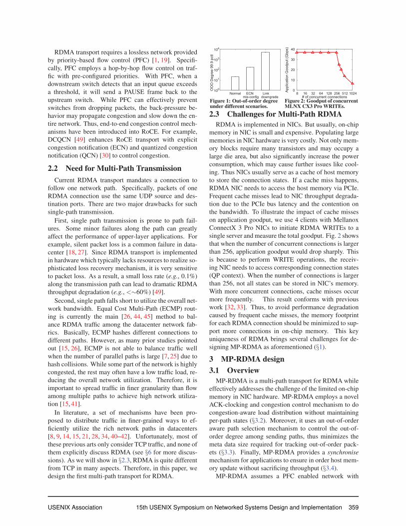
the size of the metadata could be large. Fig. 1 gives the
99.9% tail of the out-of-order degree (OOD) 3 of a net-
work under various scenarios (more details in § 5.2.1).
For example, consider the case that one path has de-
graded to 1Gbps (e.g., due to hardware failures caused
link rate auto-negotiation [9, 27]), while other paths re-
1Each sub-connection needs to maintain states including rcv nxt,snd nxt, snd una, snd ssthresh, snd cwnd, srtt, rttvar, rtt seq,
map data seq, map subseq, map data len, ...2Mellanox ConnectX Linux driver [43] maintains all the states of
an RDMA connection in a 248B mlx4 qp context.3We define the out-of-order degree (OOD) here as the maximal dif-
ference between the sequence number of an out-of-order arrived packet
and the expected packet sequence number.
USENIX Association 15th USENIX Symposium on Networked Systems Design and Implementation 357
main at a normal speed of 40Gbps. If a bitmap structure
is used, the size of the bitmap would be 1.2KB. If we
naively use fewer bits, any packet with a sequence num-
ber out of the range of the bitmap has to be dropped. This
would reduce the performance greatly as the throughput
is effectively limited by the slowest path. A core design
challenge is to keep high performance even if we can
only track very limited out-of-order packets.
Finally, the receiver NIC does not have enough mem-
ory to buffer out-of-order packets but has to place them
into host memory as they arrive. Therefore, the data in
host memory may be updated out-of-order. This may
cause a subtle issue as some existing applications implic-
itly assume the memory is updated in the same order as
the operations are posted [20, 22, 48]. For example, a
process may use a WRITE operation to update a remote
memory, and then issues another WRITE operation to
set a dirty flag to notify a remote process. If the second
WRITE updates memory before the first WRITE, the re-
mote process may prematurely read the partial data and
fails. While retaining the memory updating order is triv-
ial for single-path RDMA, it requires careful design in
multi-path RDMA to avoid performance downgrade.
This paper presents MP-RDMA, the first multi-path
transport for RDMA that addresses all aforementioned
challenges. Specifically, MP-RDMA employs a novel
multi-path ACK-clocking mechanism that can effectively
do congestion-aware packets distribution to multiple
paths without adding per-path states. Second, we design
an out-of-order aware path selection algorithm that pro-
actively prunes slow paths and adaptively chooses a set
of paths that are fast and with similar delays. This way,
MP-RDMA effectively controls the out-of-order level so
that almost all packets can be tracked with a small sized
bitmap (e.g., 64 bits). Finally, MP-RDMA provides an
interface for programmers to ensure in-order memory
update by specifying a synchronise flag to an operation.
A synchronise operation updates memory only when all
previous operations are completed. Therefore, two com-
munication nodes can coordinate their behaviors and en-
sure application logic correctness.
We have implemented an MP-RDMA prototype in
FPGA, which can run at the line rate of 40Gbps. We
evaluate MP-RDMA in a testbed with 10 servers and 6
switches. Results show that MP-RDMA can greatly im-
prove the robustness under path failures (2x∼4x higher
throughput when links have 0.5%∼10% loss rate), over-
all network utilization (∼47% higher overall throughput)
and average flow completion time (up to 17.7% reduc-
tion) compared with single-path RDMA. Moreover, MP-
RDMA only consumes a small constant (66B) amount
of extra per-connection memory, which is comparable to
the overhead (∼60B) added by DCQCN [49] to enhance
existing single-path RDMA.
In summary, we make the following contributions: 1)
We present MP-RDMA, the first transport for RDMA
that supports multi-path. 2) We have designed a set
of novel algorithms to minimize the memory footprint,
so that MP-RDMA is suitable to be implemented in
NIC hardware. 3) We have evaluated MP-RDMA on an
FPGA-based testbed as well as large-scale simulations.
2 Background and motivation2.1 RDMA Background
RDMA enables direct memory access to a remote sys-
tem through NIC hardware, by implementing the trans-port entirely in NIC. Therefore RDMA can provide low
latency and high throughput with little CPU involvement
on either local or remote end. RoCE v2 [4–6] introduces
UDP/IP/Ethernet encapsulation which allows RDMA to
run over generic IP networks. Nowadays, production
datacenters, e.g. Microsoft Azure and Google, have de-
ployed RoCE at scale [26, 39, 49]. Hereafter in this pa-
per, unless explicitly stated otherwise, we refer RDMA
to RoCE v2.
In RDMA terminology, an RDMA connection is iden-
tified by a pair of work queues, called queue pair (QP).
A QP consists of a send queue and a receive queue which
are both maintained on NICs. When an application initi-
ates an RDMA operation (also called a verb) to send or
retrieve data, it will post a work queue element (WQE) to
NIC’s send queue or receive queue, respectively. More-
over, to notify the application for operation completion,
there is also a completion queue (CQ) associated with
each QP. On completing a WQE, a completion queue el-
ement (CQE) will be delivered to the CQ. There are four
commonly used verbs in RDMA: SEND, RECV, WRITE
and READ. Among these, SEND and RECV are two-sided, meaning that SEND operation always requires a
RECV operation at the other side. READ and WRITE
are one-sided operations, meaning that applications can
directly READ or WRITE pre-registered remote memory
without involving remote CPU.
RDMA transport is message-based, i.e. an RDMA
operation is translated into a message for transmission.
Then an RDMA message will be divided into multiple
equal-sized segments which are encapsulated into UD-
P/IP/Ethernet packet(s). In RoCEv2, all RDMA pack-
ets use an identical UDP destination port (4791), while
the UDP source port is arbitrary and varies for different
connections, which allows load-balancing. An RDMA
header is attached to every packet. The header contains a
packet sequence number (PSN) which provides a contin-
uous sequence number for the RDMA packets in a con-
nection. At the receiver side, RDMA messages are re-
stored according to PSN. Moreover, an RDMA receiver
may generate an ACK or a Negative ACK (NACK) to
notify the sender for received or lost packets.
358 15th USENIX Symposium on Networked Systems Design and Implementation USENIX Association
RDMA transport requires a lossless network provided
by priority-based flow control (PFC) [1, 19]. Specifi-
cally, PFC employs a hop-by-hop flow control on traf-
fic with pre-configured priorities. With PFC, when a
downstream switch detects that an input queue exceeds
a threshold, it will send a PAUSE frame back to the
upstream switch. While PFC can effectively prevent
switches from dropping packets, the back-pressure be-
havior may propagate congestion and slow down the en-
tire network. Thus, end-to-end congestion control mech-
anisms have been introduced into RoCE. For example,
DCQCN [49] enhances RoCE transport with explicit
congestion notification (ECN) and quantized congestion
notification (QCN) [30] to control congestion.
2.2 Need for Multi-Path TransmissionCurrent RDMA transport mandates a connection to
follow one network path. Specifically, packets of one
RDMA connection use the same UDP source and des-
tination ports. There are two major drawbacks for such
single-path transmission.
First, single path transmission is prone to path fail-
ures. Some minor failures along the path can greatly
affect the performance of upper-layer applications. For
example, silent packet loss is a common failure in data-
center [18, 27]. Since RDMA transport is implemented
in hardware which typically lacks resources to realize so-
phisticated loss recovery mechanism, it is very sensitive
to packet loss. As a result, a small loss rate (e.g., 0.1%)
along the transmission path can lead to dramatic RDMA
throughput degradation (e.g., <∼60%) [49].
Second, single path falls short to utilize the overall net-
work bandwidth. Equal Cost Multi-Path (ECMP) rout-
ing is currently the main [26, 44, 45] method to bal-
ance RDMA traffic among the datacenter network fab-
rics. Basically, ECMP hashes different connections to
different paths. However, as many prior studies pointed
out [15, 26], ECMP is not able to balance traffic well
when the number of parallel paths is large [7, 25] due to
hash collisions. While some part of the network is highly
congested, the rest may often have a low traffic load, re-
ducing the overall network utilization. Therefore, it is
important to spread traffic in finer granularity than flow
among multiple paths to achieve high network utiliza-
tion [15, 41].
In literature, a set of mechanisms have been pro-
posed to distribute traffic in finer-grained ways to ef-
ficiently utilize the rich network paths in datacenters
[8, 9, 14, 15, 21, 28, 34, 40–42]. Unfortunately, most of
these previous arts only consider TCP traffic, and none of
them explicitly discuss RDMA (see §6 for more discus-
sions). As we will show in §2.3, RDMA is quite different
from TCP in many aspects. Therefore, in this paper, we
design the first multi-path transport for RDMA.
100
101
102
103
104
Normal ECN mis-config
Link downgrade
OO
O D
egre
e 99
.9 p
ctl
Figure 1: Out-of-order degreeunder different scenarios.
0
10
20
30
40
8 16 32 64 128 256 512 1024Appl
icat
ion
Goo
dput
(Gbp
s)
# of concurrent connectionsFigure 2: Goodput of concurrentMLNX CX3 Pro WRITEs.
2.3 Challenges for Multi-Path RDMARDMA is implemented in NICs. But usually, on-chip
memory in NIC is small and expensive. Populating large
memories in NIC hardware is very costly. Not only mem-
ory blocks require many transistors and may occupy a
large die area, but also significantly increase the power
consumption, which may cause further issues like cool-
ing. Thus NICs usually serve as a cache of host memory
to store the connection states. If a cache miss happens,
RDMA NIC needs to access the host memory via PCIe.
Frequent cache misses lead to NIC throughput degrada-
tion due to the PCIe bus latency and the contention on
the bandwidth. To illustrate the impact of cache misses
on application goodput, we use 4 clients with Mellanox
ConnectX 3 Pro NICs to initiate RDMA WRITEs to a
single server and measure the total goodput. Fig. 2 shows
that when the number of concurrent connections is larger
than 256, application goodput would drop sharply. This
is because to perform WRITE operations, the receiv-
ing NIC needs to access corresponding connection states
(QP context). When the number of connections is larger
than 256, not all states can be stored in NIC’s memory.
With more concurrent connections, cache misses occur
more frequently. This result conforms with previous
work [32, 33]. Thus, to avoid performance degradation
caused by frequent cache misses, the memory footprint
for each RDMA connection should be minimized to sup-
port more connections in on-chip memory. This key
uniqueness of RDMA brings several challenges for de-
signing MP-RDMA as aforementioned (§1).
3 MP-RDMA design3.1 Overview
MP-RDMA is a multi-path transport for RDMA while
effectively addresses the challenge of the limited on-chip
memory in NIC hardware. MP-RDMA employs a novel
ACK-clocking and congestion control mechanism to do
congestion-aware load distribution without maintaining
per-path states (§3.2). Moreover, it uses an out-of-order
aware path selection mechanism to control the out-of-
order degree among sending paths, thus minimizes the
meta data size required for tracking out-of-order pack-
ets (§3.3). Finally, MP-RDMA provides a synchronisemechanism for applications to ensure in order host mem-
ory update without sacrificing throughput (§3.4).
MP-RDMA assumes a PFC enabled network with
USENIX Association 15th USENIX Symposium on Networked Systems Design and Implementation 359
Ethernet Header IP Header UDP Header
VP ID (Src Port)
MSN (3B) iPSN (3B)
synchroniseReTx
RoCEv2 Data Headers
(a) MP-RDMA data packet header
Ethernet Header IP Header UDP Header RoCEv2 ACK
Headers
SACK (PSN) ECE
AACK (3B)
synchroniseReTx
Echo VP ID (Src Port)
(b) MP-RDMA ACK packet header
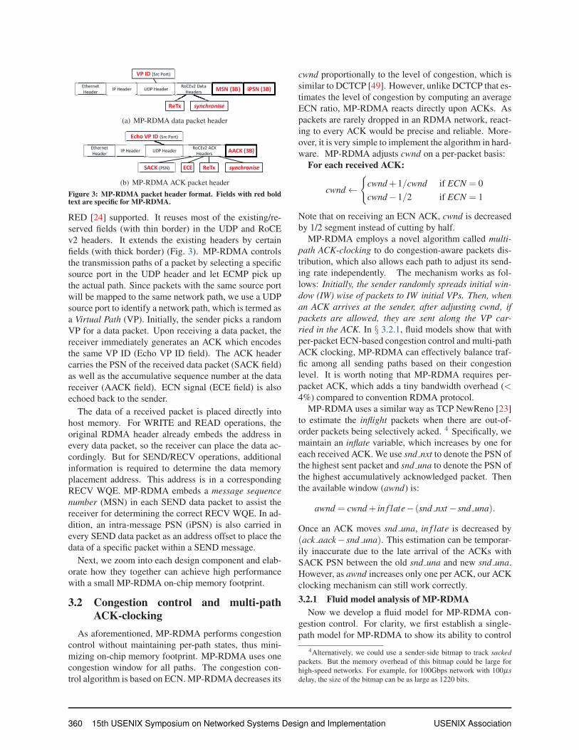
Figure 3: MP-RDMA packet header format. Fields with red boldtext are specific for MP-RDMA.
RED [24] supported. It reuses most of the existing/re-
served fields (with thin border) in the UDP and RoCE
v2 headers. It extends the existing headers by certain
fields (with thick border) (Fig. 3). MP-RDMA controls
the transmission paths of a packet by selecting a specific
source port in the UDP header and let ECMP pick up
the actual path. Since packets with the same source port
will be mapped to the same network path, we use a UDP
source port to identify a network path, which is termed as
a Virtual Path (VP). Initially, the sender picks a random
VP for a data packet. Upon receiving a data packet, the
receiver immediately generates an ACK which encodes
the same VP ID (Echo VP ID field). The ACK header
carries the PSN of the received data packet (SACK field)
as well as the accumulative sequence number at the data
receiver (AACK field). ECN signal (ECE field) is also
echoed back to the sender.
The data of a received packet is placed directly into
host memory. For WRITE and READ operations, the
original RDMA header already embeds the address in
every data packet, so the receiver can place the data ac-
cordingly. But for SEND/RECV operations, additional
information is required to determine the data memory
placement address. This address is in a corresponding
RECV WQE. MP-RDMA embeds a message sequencenumber (MSN) in each SEND data packet to assist the
receiver for determining the correct RECV WQE. In ad-
dition, an intra-message PSN (iPSN) is also carried in
every SEND data packet as an address offset to place the
data of a specific packet within a SEND message.
Next, we zoom into each design component and elab-
orate how they together can achieve high performance
with a small MP-RDMA on-chip memory footprint.
3.2 Congestion control and multi-pathACK-clocking
As aforementioned, MP-RDMA performs congestion
control without maintaining per-path states, thus mini-
mizing on-chip memory footprint. MP-RDMA uses one
congestion window for all paths. The congestion con-
trol algorithm is based on ECN. MP-RDMA decreases its
cwnd proportionally to the level of congestion, which is
similar to DCTCP [49]. However, unlike DCTCP that es-
timates the level of congestion by computing an average
ECN ratio, MP-RDMA reacts directly upon ACKs. As
packets are rarely dropped in an RDMA network, react-
ing to every ACK would be precise and reliable. More-
over, it is very simple to implement the algorithm in hard-
ware. MP-RDMA adjusts cwnd on a per-packet basis:
For each received ACK:
cwnd ←{
cwnd +1/cwnd if ECN = 0
cwnd −1/2 if ECN = 1
Note that on receiving an ECN ACK, cwnd is decreased
by 1/2 segment instead of cutting by half.
MP-RDMA employs a novel algorithm called multi-path ACK-clocking to do congestion-aware packets dis-
tribution, which also allows each path to adjust its send-
ing rate independently. The mechanism works as fol-
lows: Initially, the sender randomly spreads initial win-dow (IW) wise of packets to IW initial VPs. Then, whenan ACK arrives at the sender, after adjusting cwnd, ifpackets are allowed, they are sent along the VP car-ried in the ACK. In § 3.2.1, fluid models show that with
per-packet ECN-based congestion control and multi-path
ACK clocking, MP-RDMA can effectively balance traf-
fic among all sending paths based on their congestion
level. It is worth noting that MP-RDMA requires per-
packet ACK, which adds a tiny bandwidth overhead (<4%) compared to convention RDMA protocol.
MP-RDMA uses a similar way as TCP NewReno [23]
to estimate the inflight packets when there are out-of-
order packets being selectively acked. 4 Specifically, we
maintain an inflate variable, which increases by one for
each received ACK. We use snd nxt to denote the PSN of
the highest sent packet and snd una to denote the PSN of
the highest accumulatively acknowledged packet. Then
the available window (awnd) is:
awnd = cwnd + in f late− (snd nxt − snd una).
Once an ACK moves snd una, in f late is decreased by
(ack aack− snd una). This estimation can be temporar-
ily inaccurate due to the late arrival of the ACKs with
SACK PSN between the old snd una and new snd una.
However, as awnd increases only one per ACK, our ACK
clocking mechanism can still work correctly.
3.2.1 Fluid model analysis of MP-RDMANow we develop a fluid model for MP-RDMA con-
gestion control. For clarity, we first establish a single-
path model for MP-RDMA to show its ability to control
4Alternatively, we could use a sender-side bitmap to track sackedpackets. But the memory overhead of this bitmap could be large for
high-speed networks. For example, for 100Gbps network with 100μsdelay, the size of the bitmap can be as large as 1220 bits.
360 15th USENIX Symposium on Networked Systems Design and Implementation USENIX Association
the queue oscillation. Then a multi-path model is given
to demonstrate its ability in balancing congestion among
multiple paths. We assume all flows are synchronized,
i.e. their window dynamics are in phase.
Single-path model. Consider N long-lived flows travers-
ing a single-bottleneck link with capacity C. The fol-
lowing functions describe the dynamics of W (t) (con-
gestion window), q(t) (queue size). We use R(t) to
denote the network RT T , F(t) to denote the ratio of
ECN marked packets in the current window of pack-
ets. d is the propagation delay. We further use R∗ =d+average queue length/C to denote the average RTT.
MP-RDMA tries to strictly hold the queue length around
a fixed value, thus R∗ is fixed:
dWdt
=1−F(t −R∗)
R(t)− W (t)
2R(t)F(t −R∗) (1)
dqdt
= NW (t)R(t)
−C (2)
R(t) = d +q(t)C
(3)
The fix point of Equation (1) is: W (t) = 2(1−F)F . The
queue can be calculated as q=NW (t)−CR, which gives:
q(t) =N(1−F)
F− Cd
2(4)
MP-RDMA requires RED marking at the switch [24]:
p =
⎧⎪⎨⎪⎩
0 if q � Kmin
Pmax(q−Kmin)
Kmax−Kminif Kmin < q ≤ Kmax
1 if q > Kmax
(5)
Combining Equation (4) and (5) yields the fix point so-
lution (q,W,F). We consider two different ECN mark-
ing schemes: 1) standard RED [24]; 2) DCTCP RED
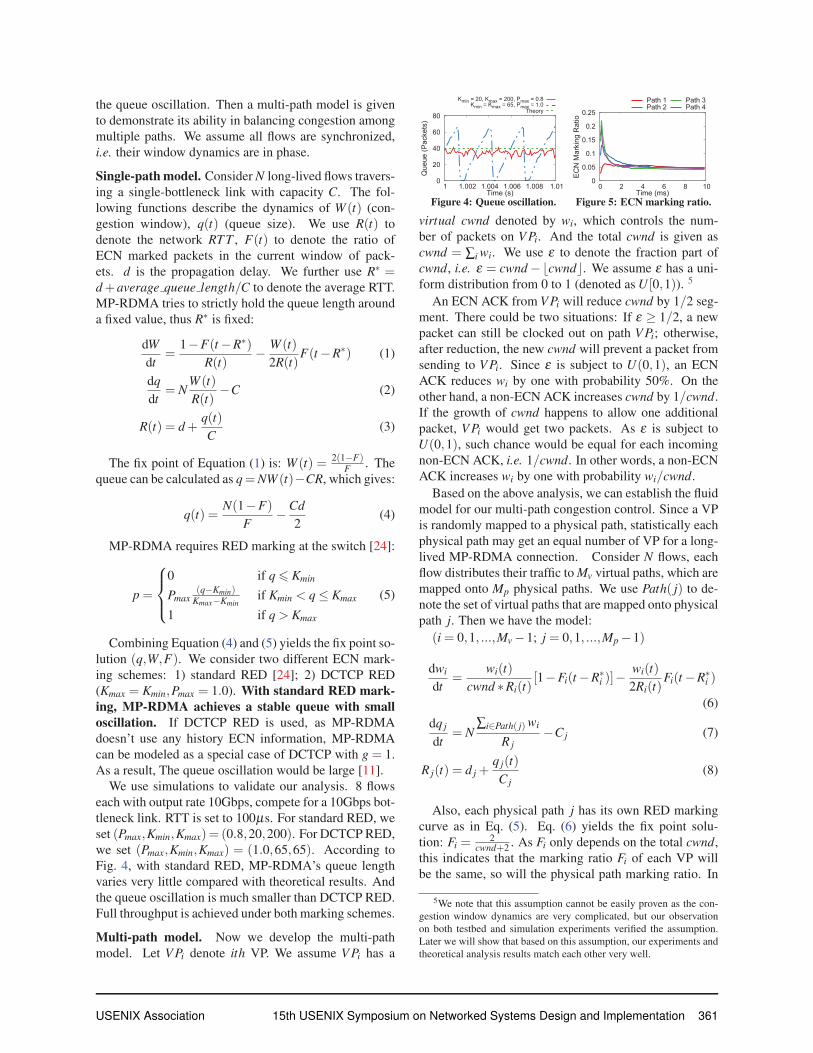
(Kmax = Kmin,Pmax = 1.0). With standard RED mark-ing, MP-RDMA achieves a stable queue with smalloscillation. If DCTCP RED is used, as MP-RDMA
doesn’t use any history ECN information, MP-RDMA
can be modeled as a special case of DCTCP with g = 1.
As a result, The queue oscillation would be large [11].
We use simulations to validate our analysis. 8 flows
each with output rate 10Gbps, compete for a 10Gbps bot-
tleneck link. RTT is set to 100μs. For standard RED, we
set (Pmax,Kmin,Kmax)= (0.8,20,200). For DCTCP RED,
we set (Pmax,Kmin,Kmax) = (1.0,65,65). According to
Fig. 4, with standard RED, MP-RDMA’s queue length
varies very little compared with theoretical results. And
the queue oscillation is much smaller than DCTCP RED.
Full throughput is achieved under both marking schemes.
Multi-path model. Now we develop the multi-path
model. Let V Pi denote ith VP. We assume V Pi has a
0
20
40
60
80
1 1.002 1.004 1.006 1.008 1.01
Que
ue (P
acke
ts)
Time (s)
Kmin = 20, Kmax = 200, Pmax = 0.8Kmin = Kmax = 65, Pmax = 1.0
Theory
Figure 4: Queue oscillation.
0
0.05
0.1
0.15
0.2
0.25
0 2 4 6 8 10
ECN
Mar
king
Rat
io
Time (ms)
Path 1Path 2
Path 3Path 4
Figure 5: ECN marking ratio.
virtual cwnd denoted by wi, which controls the num-
ber of packets on V Pi. And the total cwnd is given as
cwnd = ∑i wi. We use ε to denote the fraction part of
cwnd, i.e. ε = cwnd −�cwnd�. We assume ε has a uni-
form distribution from 0 to 1 (denoted as U [0,1)). 5
An ECN ACK from V Pi will reduce cwnd by 1/2 seg-
ment. There could be two situations: If ε ≥ 1/2, a new
packet can still be clocked out on path V Pi; otherwise,
after reduction, the new cwnd will prevent a packet from
sending to V Pi. Since ε is subject to U(0,1), an ECN
ACK reduces wi by one with probability 50%. On the
other hand, a non-ECN ACK increases cwnd by 1/cwnd.
If the growth of cwnd happens to allow one additional
packet, V Pi would get two packets. As ε is subject to
U(0,1), such chance would be equal for each incoming
non-ECN ACK, i.e. 1/cwnd. In other words, a non-ECN
ACK increases wi by one with probability wi/cwnd.
Based on the above analysis, we can establish the fluid
model for our multi-path congestion control. Since a VP
is randomly mapped to a physical path, statistically each
physical path may get an equal number of VP for a long-
lived MP-RDMA connection. Consider N flows, each
flow distributes their traffic to Mv virtual paths, which are
mapped onto Mp physical paths. We use Path( j) to de-
note the set of virtual paths that are mapped onto physical
path j. Then we have the model:
(i = 0,1, ...,Mv −1; j = 0,1, ...,Mp −1)
dwi
dt=
wi(t)cwnd ∗Ri(t)
[1−Fi(t −R∗i )]−
wi(t)2Ri(t)
Fi(t −R∗i )
(6)
dq j
dt= N
∑i∈Path( j) wi
R j−Cj (7)
R j(t) = d j +q j(t)Cj
(8)
Also, each physical path j has its own RED marking
curve as in Eq. (5). Eq. (6) yields the fix point solu-
tion: Fi =2
cwnd+2 . As Fi only depends on the total cwnd,
this indicates that the marking ratio Fi of each VP will
be the same, so will the physical path marking ratio. In
5We note that this assumption cannot be easily proven as the con-
gestion window dynamics are very complicated, but our observation
on both testbed and simulation experiments verified the assumption.
Later we will show that based on this assumption, our experiments and
theoretical analysis results match each other very well.
USENIX Association 15th USENIX Symposium on Networked Systems Design and Implementation 361
other words, MP-RDMA can balance the ECN mark-ing ratio among all sending paths regardless of theirRTTs, capacities and RED marking curves. In data-
centers where all equal-cost paths have same capacities
and RED marking curves, MP-RDMA can balance the
load among multiple paths.
We use simulations to validate our conclusion. 10
MP-RDMA connections are established. Each sends at
40Gbps among 8 VPs. The virtual paths are mapped
randomly onto 4 physical paths with different rates, i.e.20Gbps, 40Gbps, 60Gbps and 80Gbps. The network
base RTT of each path is set to 16μs. For RED mark-
ing, all paths has the same Kmin = 20 and Kmax = 200,
but with Pmax set to different values, i.e. 0.2, 0.4, 0.6 and
0.8. Fig. 5 shows the ECN marking ratio of the 4 phys-
ical paths. ECN marking ratios of the 4 physical paths
converge to the same value which validates our analysis.
3.3 Out-of-order aware path selectionOut-of-Order (OOO) is a common outcome due to the
parallelism of multi-path transmission. This section first
introduces the data structure for tracking OOO packets.
Then we discuss the mechanism to control the network
OOO degree to an acceptable level so that the on-chip
memory footprint can be minimized.
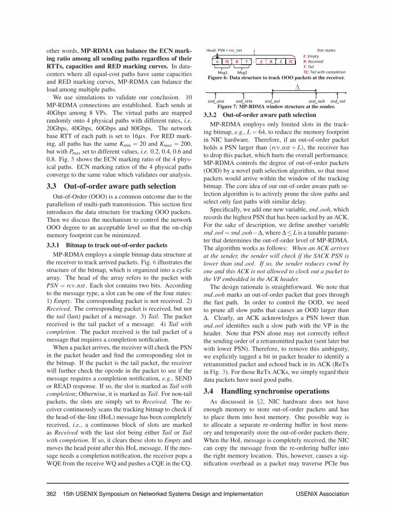
3.3.1 Bitmap to track out-of-order packetsMP-RDMA employs a simple bitmap data structure at
the receiver to track arrived packets. Fig. 6 illustrates the
structure of the bitmap, which is organized into a cyclic
array. The head of the array refers to the packet with
PSN = rcv nxt. Each slot contains two bits. According
to the message type, a slot can be one of the four states:
1) Empty. The corresponding packet is not received. 2)
Received. The corresponding packet is received, but not
the tail (last) packet of a message. 3) Tail. The packet
received is the tail packet of a message. 4) Tail withcompletion. The packet received is the tail packet of a
message that requires a completion notification.
When a packet arrives, the receiver will check the PSN
in the packet header and find the corresponding slot in
the bitmap. If the packet is the tail packet, the receiver
will further check the opcode in the packet to see if the
message requires a completion notification, e.g., SEND
or READ response. If so, the slot is marked as Tail withcompletion; Otherwise, it is marked as Tail. For non-tail
packets, the slots are simply set to Received. The re-
ceiver continuously scans the tracking bitmap to check if
the head-of-the-line (HoL) message has been completely
received, i.e., a continuous block of slots are marked
as Received with the last slot being either Tail or Tailwith completion. If so, it clears these slots to Empty and
moves the head point after this HoL message. If the mes-
sage needs a completion notification, the receiver pops a
WQE from the receive WQ and pushes a CQE in the CQ.
Msg2
LHead: PSN = rcv_nxt
R TC R T E R E TC
Msg1
...
Lead: PSN rcv_nxt
R TC R T E R E TC
Msg1 Msg2
E: Empty R: Received T: Tail TC: Tail with completion
Slot states
Figure 6: Data structure to track OOO packets at the receiver.
snd_una snd_oohsnd_ool snd_nxtsnd_retx
Figure 7: MP-RDMA window structure at the sender.
3.3.2 Out-of-order aware path selectionMP-RDMA employs only limited slots in the track-
ing bitmap, e.g., L = 64, to reduce the memory footprint
in NIC hardware. Therefore, if an out-of-order packet
holds a PSN larger than (rcv nxt + L), the receiver has
to drop this packet, which hurts the overall performance.
MP-RDMA controls the degree of out-of-order packets
(OOD) by a novel path selection algorithm, so that most
packets would arrive within the window of the tracking
bitmap. The core idea of our out-of-order aware path se-
lection algorithm is to actively prune the slow paths and
select only fast paths with similar delay.
Specifically, we add one new variable, snd ooh, which
records the highest PSN that has been sacked by an ACK.
For the sake of description, we define another variable
snd ool = snd ooh−Δ, where Δ≤ L is a tunable parame-
ter that determines the out-of-order level of MP-RDMA.
The algorithm works as follows: When an ACK arrivesat the sender, the sender will check if the SACK PSN islower than snd ool. If so, the sender reduces cwnd byone and this ACK is not allowed to clock out a packet tothe VP embedded in the ACK header.
The design rationale is straightforward. We note that
snd ooh marks an out-of-order packet that goes through
the fast path. In order to control the OOD, we need
to prune all slow paths that causes an OOD larger than
Δ. Clearly, an ACK acknowledges a PSN lower than
snd ool identifies such a slow path with the VP in the
header. Note that PSN alone may not correctly reflect
the sending order of a retransmitted packet (sent later but
with lower PSN). Therefore, to remove this ambiguity,
we explicitly tagged a bit in packet header to identify a
retransmitted packet and echoed back in its ACK (ReTx
in Fig. 3). For those ReTx ACKs, we simply regard their
data packets have used good paths.
3.4 Handling synchronise operationsAs discussed in §2, NIC hardware does not have
enough memory to store out-of-order packets and has
to place them into host memory. One possible way is
to allocate a separate re-ordering buffer in host mem-
ory and temporarily store the out-of-order packets there.
When the HoL message is completely received, the NIC
can copy the message from the re-ordering buffer into
the right memory location. This, however, causes a sig-
nification overhead as a packet may traverse PCIe bus
362 15th USENIX Symposium on Networked Systems Design and Implementation USENIX Association
twice, which not only consumes double PCIe bandwidth
resource but also incurs a long delay. We choose to di-
rectly place out-of-order packets’ data into application
memory. This approach is simple and achieves optimal
performance in most cases. However, to support applica-
tions that rely on the strict order of memory updates, e.g.,key-value store using RDMA WRITE operations [20],
MP-RDMA allows programmers to specify a synchro-nise flag on an operation, and MP-RDMA ensures that a
synchronise operation updates the memory only after all
previous operations are completed.
One straightforward approach is to delay a synchro-
nise operation until the initiator receives acknowledge-
ments or data (for READ verbs) of all previous opera-
tions. This may cause inferior performance as one ad-
ditional RTT will be added to every synchronise opera-
tion. We mitigate this penalty by delaying synchronise
operations only an interval that is slightly larger than the
maximum delay difference among all paths. In this way,
the synchronise operations should complete just after all
its previous messages with high probability. With the
out-of-order aware path selection mechanism (§3.3), this
delay interval can be easily estimated as
Δt = α ·Δ/Rs = α ·Δ/(
cwndRT T
),
where Δ is the target out-of-order level, Rs is the sending
rate of the RDMA connection and α is a scaling fac-
tor. We note that synchronise messages could still arrive
before other earlier messages. In these rare cases, to en-
sure correctness, the receiver may drop the synchronise
message and send a NACK, which allows the sender to
retransmit the message later.
3.5 Other design details and discussionsLoss recovery. For single-path RDMA, packet loss
is detected by the gap in PSNs. But in MP-RDMA,
out-of-order packets are common and most of them are
not related to packet losses. MP-RDMA combines loss
detection with the out-of-order aware path selection al-
gorithm. In normal situations, the algorithm controls
OOD to be around Δ. However, if a packet gets lost,
OOD will continuously increase until it is larger than
the size of the tracking bitmap. Then, a NACK will
be generated by the receiver to notify the PSN of the
lost packet. Upon a NACK, MP-RDMA enters recovery
mode. Specifically, we store the current snd nxt value
into to a variable called recovery and set snd retx to the
NACKed PSN (Fig.7). In the recovery mode, an incom-
ing ACK clocks out a retransmission packet indicated by
snd retx, instead of a new packet. If snd una moves be-
yond recovery, the loss recovery mode ends.
There is one subtle issue here. Since MP-RDMA en-
ters recovery mode only upon bitmap overflow, if the
application does not have that much data to send, RTO
is triggered. To avoid this RTO, we adopt a scheme of
FUSO [18] that early retransmits unacknowledged pack-
ets as new data if there is no new data to transmit and
awnd allows. In rare case that the retransmissions are
also lost, RTO will eventually fire and the sender will
start to retransmit all unacknowledged packets.
New path probing. MP-RDMA periodically probes
new paths to find better ones. Specifically, every RTT,
with a probability p, the sender sends a packet to a new
random VP, instead of the VP of the ACK. This p bal-
ances the the chance to fully utilize the current set of
good paths and to find even better paths. In our experi-
ment, we set p to 1%.
Burst control. Sometimes for a one returned ACK,
the sender may have a burst of packets (≥2) to send, e.g.,after exiting recovery mode. If all those packets are sent
to the ACK’s VP, the congestion may deteriorate. MP-
RDMA forces that one ACK can clock out at most two
data packets. The rest packets will gradually be clocked
out by successive ACKs. If no subsequent ACKs return,
these packets will be clocked out by a burst timer to ran-
dom VPs. The timer length is set to wait for outstanding
packets to be drained from the network, e.g. 1/2 RTT.
Path window reduction. If there is no new data to
transfer, MP-RDMA gracefully shrinks cwnd and reduce
the sending rate accordingly following a principle called
“use it or lose it”. Specifically, if the sender receives an
ACK that should kick out a new packet but there is no
new data available, cwnd is reduced by one. This mech-
anism ensures that all sending paths adjust their rates in-
dependently. If path window reduction mechanism is not
used, the sending window opened up by an old ACK may
result in data transmission on an already congested path,
thus deteriorating the congestion.
Connection restart. When applications start to trans-
mit data after idle (e.g. 3 RTTs), MP-RDMA will restart
from IW and restore multi-path ACK clocking. This is
similar to the restart after idle problem in TCP [29].
Interact with PFC. With our ECN-based end-to-end
congestion control, PFC will seldom be triggered. If
PFC pauses all transmission paths [26, 49], MP-RDMA
will stop sending since no ACK returns. When PFC re-
sumes, ACK clocking will be restarted. If only a sub-
set of paths are paused by PFC, those paused paths will
gradually be eliminated by the OOO-aware path selec-
tion due to their longer delay. We have confirmed above
arguments through simulations. We omit the results here
due to space limitation.
4 Implementation4.1 FPGA-based Prototype
We have implemented an MP-RDMA prototype using
Altera Stratix V D5 FPGA board [12] with a PCIe Gen3
USENIX Association 15th USENIX Symposium on Networked Systems Design and Implementation 363
MP-RDMA Library
Application
Application Data Buffer
MP-RDMA Transport Logic
Host
FPGA
40G Ethernet Port
ToR Switch
MP-RDMA Transport Logic
FPGA
40G Ethernet Port
DMA
PCIe
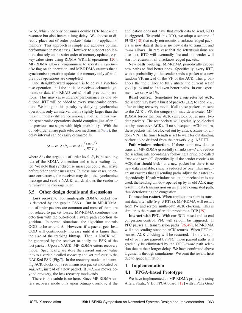
Figure 8: System architecture.
x8 interface and two 40G Ethernet ports. Fig.8 shows the
overview of the prototype architecture. There are two
major components: 1) MP-RDMA transport logic, and
2) MP-RDMA library. The entire transport logic is im-
plemented on FPGA with ClickNP framework [35]. We
have developed 14 ClickNP elements with ∼2K lines of
OpenCL code. Applications call MP-RDMA library to
issue operations to the transport. FPGA directly DMAs
packet data from/to the application buffer via PCIe.
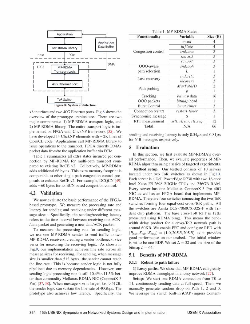
Table 1 summarizes all extra states incurred per con-
nection by MP-RDMA for multi-path transport com-
pared to existing RoCE v2. Collectively, MP-RDMA
adds additional 66 bytes. This extra memory footprint is
comparable to other single-path congestion control pro-
posals to enhance RoCE v2. For example, DCQCN [49]
adds ∼60 bytes for its ECN based congestion control.
4.2 ValidationWe now evaluate the basic performance of the FPGA-
based prototype. We measure the processing rate and
latency for sending and receiving under different mes-
sage sizes. Specifically, the sending/receiving latency
refers to the time interval between receiving one ACK-
/data packet and generating a new data/ACK packet.
To measure the processing rate for sending logic,
we use one MP-RDMA sender to send traffic to two
MP-RDMA receivers, creating a sender bottleneck, vice
versa for measuring the receiving logic. As shown in
Fig.9, our implementation achieves line rate across all
message sizes for receiving. For sending, when message
size is smaller than 512 bytes, the sender cannot reach
the line rate. This is because sender logic is not fully
pipelined due to memory dependencies. However, our
sending logic processing rate is still 10.4%∼11.5% bet-
ter than commodity Mellanox RDMA NIC (ConnectX-3
Pro) [37, 38]. When message size is larger, i.e. >512B,
the sender logic can sustain the line-rate of 40Gbps. The
prototype also achieves low latency. Specifically, the
Table 1: MP-RDMA States
Functionality Variable Size (B)
Congestion control
cwnd 4
in f late 4
snd una 3
snd nxt 3
rcv nxt 3
OOO-aware
path selection
snd ooh 3
L 1
Loss recoverysnd retx 3
recovery 3
Path probingMaxPathID 2
p 1
Tracking
OOO packets
bitmap data 16
bitmap head 1
Burst Control burst timer 3
Connection restart restart timer 3
Synchronise message α 1
RTT measurement srtt, rttvar, rtt seq 12
Total N/A 66
sending and receiving latency is only 0.54μs and 0.81μs
for 64B messages respectively.
5 EvaluationIn this section, we first evaluate MP-RDMA’s over-
all performance. Then, we evaluate properties of MP-
RDMA algorithm using a series of targeted experiments.
Testbed setup. Our testbed consists of 10 servers
located under two ToR switches as shown in Fig.10.
Each server is a Dell PowerEdge R730 with two 16-core
Intel Xeon E5-2698 2.3GHz CPUs and 256GB RAM.
Every server has one Mellanox ConnectX-3 Pro 40G
NIC as well as an FPGA board that implements MP-
RDMA. There are four switches connecting the two ToR
switches forming four equal-cost cross-ToR paths. All
the switches are Arista DCS-7060CX-32S-F with Tri-
dent chip platform. The base cross-ToR RTT is 12μs(measured using RDMA ping). This means the band-
width delay product for a cross-ToR network path is
around 60KB. We enable PFC and configure RED with
(Pmax,Kmin,Kmax) = (1.0,20KB,20KB) as it provides
good performance on our testbed. The initial window
is set to be one BDP. We set Δ = 32 and the size of the
bitmap L = 64.
5.1 Benefits of MP-RDMA5.1.1 Robust to path failure
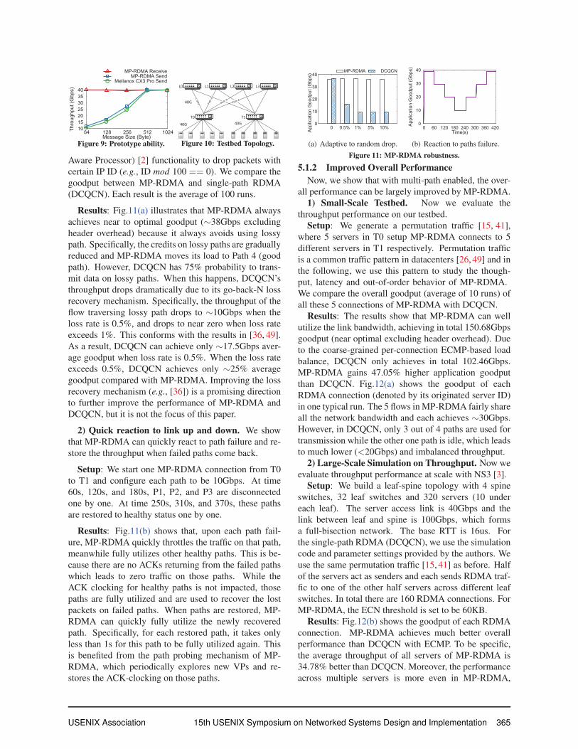
1) Lossy paths. We show that MP-RDMA can greatly
improve RDMA throughput in a lossy network [27].
Setup: We start one RDMA connection from T0 to
T1, continuously sending data at full speed. Then, we
manually generate random drop on Path 1, 2 and 3.
We leverage the switch built-in iCAP (ingress Content-
364 15th USENIX Symposium on Networked Systems Design and Implementation USENIX Association
10 15 20 25 30 35 40
64 128 256 512 1024Thro
ughp
ut (G
bps)
Message Size (Byte)
MP-RDMA ReceiveMP-RDMA Send
Mellanox CX3 Pro Send
Figure 9: Prototype ability.
T0 T1
L1 L2 L3L0
40G 40G
40G
Figure 10: Testbed Topology.
Aware Processor) [2] functionality to drop packets with
certain IP ID (e.g., ID mod 100 == 0). We compare the
goodput between MP-RDMA and single-path RDMA
(DCQCN). Each result is the average of 100 runs.
Results: Fig.11(a) illustrates that MP-RDMA always
achieves near to optimal goodput (∼38Gbps excluding
header overhead) because it always avoids using lossy
path. Specifically, the credits on lossy paths are gradually
reduced and MP-RDMA moves its load to Path 4 (good
path). However, DCQCN has 75% probability to trans-
mit data on lossy paths. When this happens, DCQCN’s
throughput drops dramatically due to its go-back-N loss
recovery mechanism. Specifically, the throughput of the
flow traversing lossy path drops to ∼10Gbps when the
loss rate is 0.5%, and drops to near zero when loss rate
exceeds 1%. This conforms with the results in [36, 49].
As a result, DCQCN can achieve only ∼17.5Gbps aver-
age goodput when loss rate is 0.5%. When the loss rate
exceeds 0.5%, DCQCN achieves only ∼25% average
goodput compared with MP-RDMA. Improving the loss
recovery mechanism (e.g., [36]) is a promising direction
to further improve the performance of MP-RDMA and
DCQCN, but it is not the focus of this paper.
2) Quick reaction to link up and down. We show
that MP-RDMA can quickly react to path failure and re-
store the throughput when failed paths come back.
Setup: We start one MP-RDMA connection from T0
to T1 and configure each path to be 10Gbps. At time
60s, 120s, and 180s, P1, P2, and P3 are disconnected
one by one. At time 250s, 310s, and 370s, these paths
are restored to healthy status one by one.
Results: Fig.11(b) shows that, upon each path fail-
ure, MP-RDMA quickly throttles the traffic on that path,
meanwhile fully utilizes other healthy paths. This is be-
cause there are no ACKs returning from the failed paths
which leads to zero traffic on those paths. While the
ACK clocking for healthy paths is not impacted, those
paths are fully utilized and are used to recover the lost
packets on failed paths. When paths are restored, MP-
RDMA can quickly fully utilize the newly recovered
path. Specifically, for each restored path, it takes only
less than 1s for this path to be fully utilized again. This
is benefited from the path probing mechanism of MP-
RDMA, which periodically explores new VPs and re-
stores the ACK-clocking on those paths.
0
10
20
30
40
0 0.5% 1% 5% 10%
Appl
icat
ion
Goo
dput
(Gbp
s)
MP-RDMA DCQCN
(a) Adaptive to random drop.
0
10
20
30
40
0 60 120 180 240 300 360 420Appl
icat
ion
Goo
dput
(Gbp
s)
Time(s)
(b) Reaction to paths failure.
Figure 11: MP-RDMA robustness.
5.1.2 Improved Overall PerformanceNow, we show that with multi-path enabled, the over-
all performance can be largely improved by MP-RDMA.
1) Small-Scale Testbed. Now we evaluate the
throughput performance on our testbed.
Setup: We generate a permutation traffic [15, 41],
where 5 servers in T0 setup MP-RDMA connects to 5
different servers in T1 respectively. Permutation traffic
is a common traffic pattern in datacenters [26, 49] and in
the following, we use this pattern to study the though-
put, latency and out-of-order behavior of MP-RDMA.
We compare the overall goodput (average of 10 runs) of
all these 5 connections of MP-RDMA with DCQCN.
Results: The results show that MP-RDMA can well
utilize the link bandwidth, achieving in total 150.68Gbps
goodput (near optimal excluding header overhead). Due
to the coarse-grained per-connection ECMP-based load
balance, DCQCN only achieves in total 102.46Gbps.
MP-RDMA gains 47.05% higher application goodput
than DCQCN. Fig.12(a) shows the goodput of each
RDMA connection (denoted by its originated server ID)
in one typical run. The 5 flows in MP-RDMA fairly share
all the network bandwidth and each achieves ∼30Gbps.
However, in DCQCN, only 3 out of 4 paths are used for
transmission while the other one path is idle, which leads
to much lower (<20Gbps) and imbalanced throughput.
2) Large-Scale Simulation on Throughput. Now we
evaluate throughput performance at scale with NS3 [3].
Setup: We build a leaf-spine topology with 4 spine
switches, 32 leaf switches and 320 servers (10 under
each leaf). The server access link is 40Gbps and the
link between leaf and spine is 100Gbps, which forms
a full-bisection network. The base RTT is 16us. For
the single-path RDMA (DCQCN), we use the simulation
code and parameter settings provided by the authors. We
use the same permutation traffic [15, 41] as before. Half
of the servers act as senders and each sends RDMA traf-
fic to one of the other half servers across different leaf
switches. In total there are 160 RDMA connections. For
MP-RDMA, the ECN threshold is set to be 60KB.
Results: Fig.12(b) shows the goodput of each RDMA
connection. MP-RDMA achieves much better overall
performance than DCQCN with ECMP. To be specific,
the average throughput of all servers of MP-RDMA is
34.78% better than DCQCN. Moreover, the performance
across multiple servers is more even in MP-RDMA,
USENIX Association 15th USENIX Symposium on Networked Systems Design and Implementation 365
0
10
20
30
40
0 1 2 3 4Appl
icat
ion
Goo
dput
(Gbp
s)
Server ID
MP-RDMA DCQCN
(a) Small-scale testbed.
0
10
20
30
40
0 20 40 60 80 100 120 140 160Appl
icat
ion
Goo
dput
(Gbp
s)
Server ID
MP-RDMA DCQCN
(b) Large-scale simulation.
Figure 12: Overall throughput compared with DCQCN.
where the lowest connection throughput can still achieve
32.95Gbps. However, in DCQCN, many unlucky flows
are congested into a single path, leading to a very low
throughout (e.g., <15Gbps) for them.
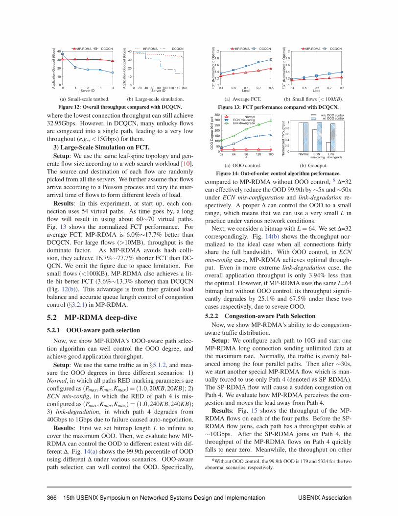
3) Large-Scale Simulation on FCT.Setup: We use the same leaf-spine topology and gen-
erate flow size according to a web search workload [10].
The source and destination of each flow are randomly
picked from all the servers. We further assume that flows
arrive according to a Poisson process and vary the inter-
arrival time of flows to form different levels of load.
Results: In this experiment, at start up, each con-
nection uses 54 virtual paths. As time goes by, a long
flow will result in using about 60∼70 virtual paths.
Fig. 13 shows the normalized FCT performance. For
average FCT, MP-RDMA is 6.0%∼17.7% better than
DCQCN. For large flows (>10MB), throughput is the
dominate factor. As MP-RDMA avoids hash colli-
sion, they achieve 16.7%∼77.7% shorter FCT than DC-
QCN. We omit the figure due to space limitation. For
small flows (<100KB), MP-RDMA also achieves a lit-
tle bit better FCT (3.6%∼13.3% shorter) than DCQCN
(Fig. 12(b)). This advantage is from finer grained load
balance and accurate queue length control of congestion
control (§3.2.1) in MP-RDMA.
5.2 MP-RDMA deep-dive5.2.1 OOO-aware path selection
Now, we show MP-RDMA’s OOO-aware path selec-
tion algorithm can well control the OOO degree, and
achieve good application throughput.
Setup: We use the same traffic as in §5.1.2, and mea-
sure the OOO degrees in three different scenarios: 1)
Normal, in which all paths RED marking parameters are
configured as (Pmax,Kmin,Kmax) = (1.0,20KB,20KB); 2)
ECN mis-config, in which the RED of path 4 is mis-
configured as (Pmax,Kmin,Kmax) = (1.0,240KB,240KB);3) link-degradation, in which path 4 degrades from
40Gbps to 1Gbps due to failure caused auto-negotiation.
Results: First we set bitmap length L to infinite to
cover the maximum OOD. Then, we evaluate how MP-
RDMA can control the OOD to different extent with dif-
ferent Δ. Fig. 14(a) shows the 99.9th percentile of OOD
using different Δ under various scenarios. OOO-aware
path selection can well control the OOD. Specifically,
1
1.2
1.4
1.6
1.8
2
0.4 0.5 0.6 0.7 0.8FCT
(Nor
mal
ized
to O
ptim
al)
Load
MP-RDMA DCQCN
(a) Average FCT.
1
1.2
1.4
1.6
1.8
2
0.4 0.5 0.6 0.7 0.8FCT
(Nor
mal
ized
to O
ptim
al)
Load
MP-RDMA DCQCN
(b) Small flows (< 100KB).
Figure 13: FCT performance compared with DCQCN.
0 50
100 150 200 250 300 350
32 64 96 128 160
OO
O D
egre
e 99
.9 p
ctl
Δ
NormalECN mis-configLink downgrade
(a) OOO control.
0
0.2
0.4
0.6
0.8
1
Normal ECN mis-config
Link downgradeN
orm
ailiz
ed T
hrou
ghpu
t
w/o OOO controlw/ OOO control
(b) Goodput.
Figure 14: Out-of-order control algorithm performance.
compared to MP-RDMA without OOO control, 6 Δ=32
can effectively reduce the OOD 99.9th by ∼5x and ∼50x
under ECN mis-configuration and link-degradation re-
spectively. A proper Δ can control the OOD to a small
range, which means that we can use a very small L in
practice under various network conditions.
Next, we consider a bitmap with L = 64. We set Δ=32
correspondingly. Fig. 14(b) shows the throughput nor-
malized to the ideal case when all connections fairly
share the full bandwidth. With OOO control, in ECNmis-config case, MP-RDMA achieves optimal through-
put. Even in more extreme link-degradation case, the
overall application throughput is only 3.94% less than
the optimal. However, if MP-RDMA uses the same L=64
bitmap but without OOO control, its throughput signifi-
cantly degrades by 25.1% and 67.5% under these two
cases respectively, due to severe OOO.
5.2.2 Congestion-aware Path SelectionNow, we show MP-RDMA’s ability to do congestion-
aware traffic distribution.
Setup: We configure each path to 10G and start one
MP-RDMA long connection sending unlimited data at
the maximum rate. Normally, the traffic is evenly bal-
anced among the four parallel paths. Then after ∼30s,
we start another special MP-RDMA flow which is man-
ually forced to use only Path 4 (denoted as SP-RDMA).
The SP-RDMA flow will cause a sudden congestion on
Path 4. We evaluate how MP-RDMA perceives the con-
gestion and moves the load away from Path 4.
Results: Fig. 15 shows the throughput of the MP-
RDMA flows on each of the four paths. Before the SP-
RDMA flow joins, each path has a throughput stable at
∼10Gbps. After the SP-RDMA joins on Path 4, the
throughput of the MP-RDMA flows on Path 4 quickly
falls to near zero. Meanwhile, the throughput on other
6Without OOO control, the 99.9th OOD is 179 and 5324 for the two
abnormal scenarios, respectively.
366 15th USENIX Symposium on Networked Systems Design and Implementation USENIX Association
0
2
4
6
8
10
0 10 20 30 40 50Link
Thr
ough
put (
Gbp
s)
Time(s)
path1path2
path3path4
Figure 15: Path selection.
0 5
10 15 20 25 30 35 40
0 90 180 270 360 450Appl
icat
ion
Goo
dput
(Gbp
s)
Time(s)
c1c2
c3c4
c5c6
c7c8
Figure 16: MP-RDMA Fairness.
3 paths all remains at around 10Gbps. This indicates
that MP-RDMA can quickly perceive the congestion on
Path 4, and moves the load away from this path. Also,
since the congestion conditions on other paths remain un-
changed, MP-RDMA does not adjust the load on them.
Here we don’t focus on the fairness between SP-RDMA
and MP-RDMA connections.
5.2.3 Fairness of MP-RDMASetup: In this experiment, two physical servers un-
der one ToR establish multiple MP-RDMA connections
to another server under the same ToR creating a single
bottleneck. 8 MP-RDMA connections are started one by
one with an interval of 30s, and then leaves the network
one after another with the same time interval. We mea-
sure the application goodput of each connection.
Results: Fig. 16 shows that all flows evenly share the
network, and get the fair share quickly. Specifically, each
connection’s throughput quickly converges to ∼ 40n Gbps,
when n varies from 1 to 8 and then 8 to 1. The Jain
fairness index [31] is within 0.996 - 0.999 (1 is optimal)
under various number of concurrent flows.
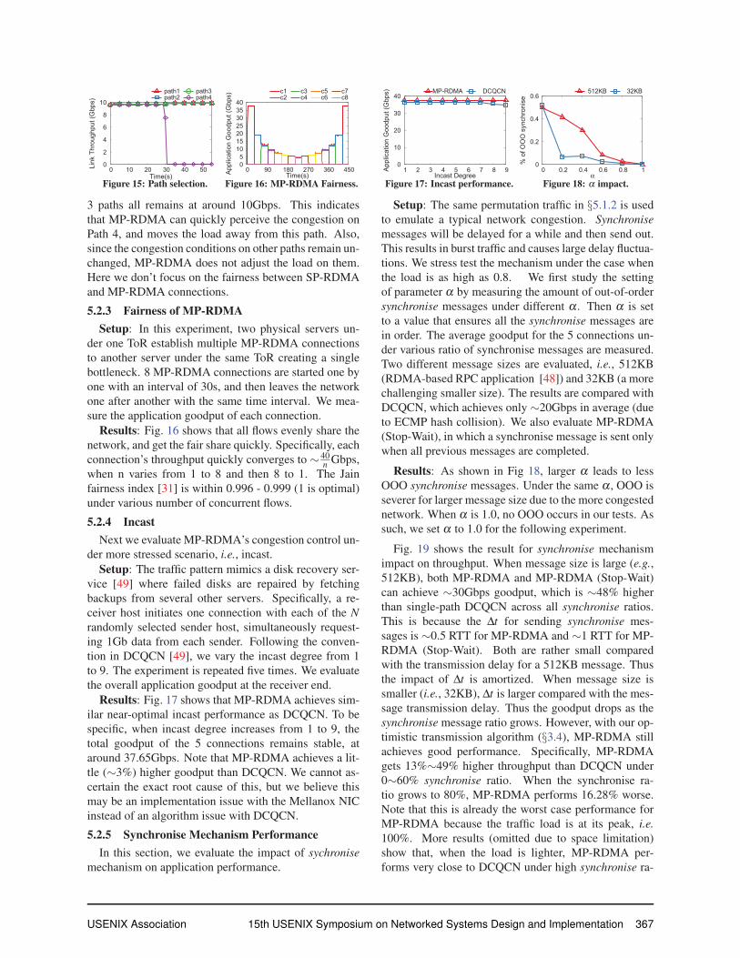
5.2.4 IncastNext we evaluate MP-RDMA’s congestion control un-
der more stressed scenario, i.e., incast.
Setup: The traffic pattern mimics a disk recovery ser-
vice [49] where failed disks are repaired by fetching
backups from several other servers. Specifically, a re-
ceiver host initiates one connection with each of the Nrandomly selected sender host, simultaneously request-
ing 1Gb data from each sender. Following the conven-
tion in DCQCN [49], we vary the incast degree from 1
to 9. The experiment is repeated five times. We evaluate
the overall application goodput at the receiver end.
Results: Fig. 17 shows that MP-RDMA achieves sim-
ilar near-optimal incast performance as DCQCN. To be
specific, when incast degree increases from 1 to 9, the
total goodput of the 5 connections remains stable, at
around 37.65Gbps. Note that MP-RDMA achieves a lit-
tle (∼3%) higher goodput than DCQCN. We cannot as-
certain the exact root cause of this, but we believe this
may be an implementation issue with the Mellanox NIC
instead of an algorithm issue with DCQCN.
5.2.5 Synchronise Mechanism PerformanceIn this section, we evaluate the impact of sychronise
mechanism on application performance.
0
10
20
30
40
1 2 3 4 5 6 7 8 9Appl
icat
ion
Goo
dput
(Gbp
s)
Incast Degree
MP-RDMA DCQCN
Figure 17: Incast performance.
0
0.2
0.4
0.6
0 0.2 0.4 0.6 0.8 1
% o
f OO
O s
ynch
roni
se
α
512KB 32KB
Figure 18: α impact.
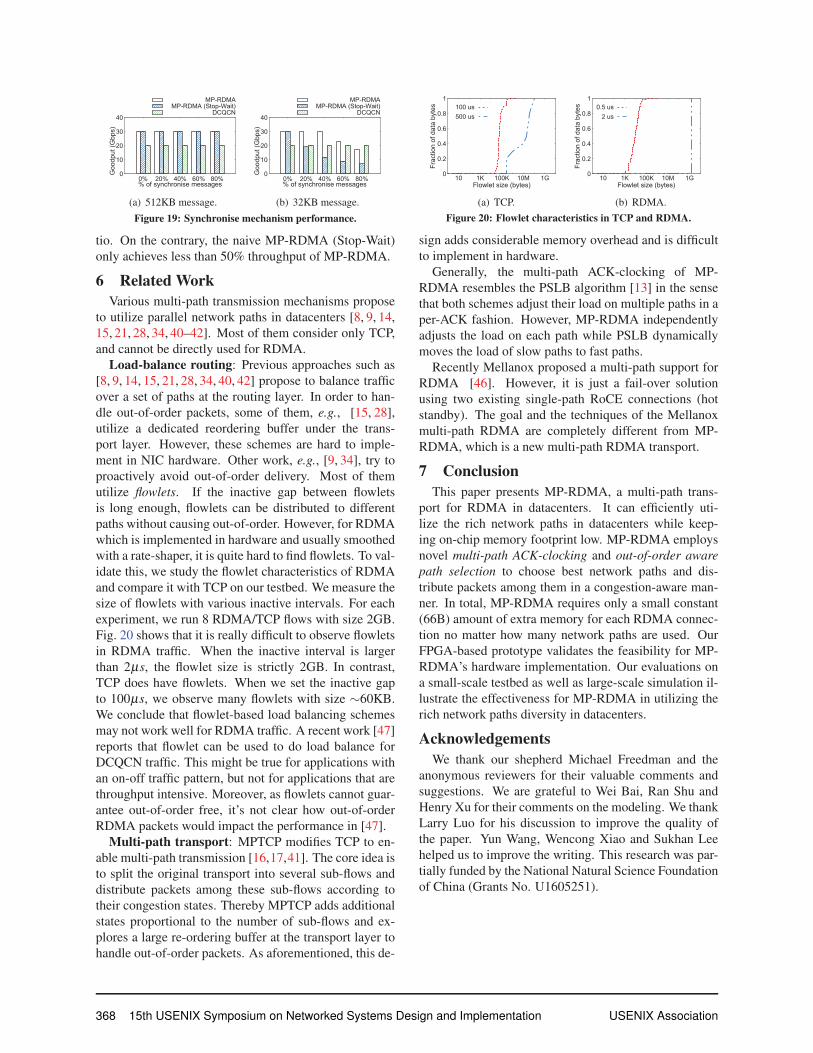
Setup: The same permutation traffic in §5.1.2 is used
to emulate a typical network congestion. Synchronisemessages will be delayed for a while and then send out.
This results in burst traffic and causes large delay fluctua-
tions. We stress test the mechanism under the case when
the load is as high as 0.8. We first study the setting
of parameter α by measuring the amount of out-of-order
synchronise messages under different α . Then α is set
to a value that ensures all the synchronise messages are
in order. The average goodput for the 5 connections un-
der various ratio of synchronise messages are measured.
Two different message sizes are evaluated, i.e., 512KB
(RDMA-based RPC application [48]) and 32KB (a more
challenging smaller size). The results are compared with
DCQCN, which achieves only ∼20Gbps in average (due
to ECMP hash collision). We also evaluate MP-RDMA
(Stop-Wait), in which a synchronise message is sent only
when all previous messages are completed.
Results: As shown in Fig 18, larger α leads to less
OOO synchronise messages. Under the same α , OOO is
severer for larger message size due to the more congested
network. When α is 1.0, no OOO occurs in our tests. As
such, we set α to 1.0 for the following experiment.
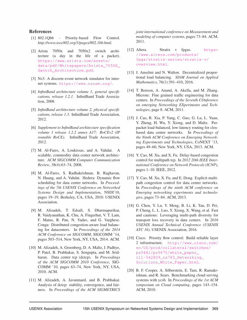
Fig. 19 shows the result for synchronise mechanism
impact on throughput. When message size is large (e.g.,512KB), both MP-RDMA and MP-RDMA (Stop-Wait)
can achieve ∼30Gbps goodput, which is ∼48% higher
than single-path DCQCN across all synchronise ratios.
This is because the Δt for sending synchronise mes-
sages is ∼0.5 RTT for MP-RDMA and ∼1 RTT for MP-
RDMA (Stop-Wait). Both are rather small compared
with the transmission delay for a 512KB message. Thus
the impact of Δt is amortized. When message size is
smaller (i.e., 32KB), Δt is larger compared with the mes-
sage transmission delay. Thus the goodput drops as the
synchronise message ratio grows. However, with our op-
timistic transmission algorithm (§3.4), MP-RDMA still
achieves good performance. Specifically, MP-RDMA
gets 13%∼49% higher throughput than DCQCN under
0∼60% synchronise ratio. When the synchronise ra-
tio grows to 80%, MP-RDMA performs 16.28% worse.
Note that this is already the worst case performance for
MP-RDMA because the traffic load is at its peak, i.e.100%. More results (omitted due to space limitation)
show that, when the load is lighter, MP-RDMA per-
forms very close to DCQCN under high synchronise ra-
USENIX Association 15th USENIX Symposium on Networked Systems Design and Implementation 367
0
10
20
30
40
0% 20% 40% 60% 80%
Goo
dput
(Gbp
s)
% of synchronise messages
MP-RDMAMP-RDMA (Stop-Wait)
DCQCN
(a) 512KB message.
0
10
20
30
40
0% 20% 40% 60% 80%
Goo
dput
(Gbp
s)
% of synchronise messages
MP-RDMAMP-RDMA (Stop-Wait)
DCQCN
(b) 32KB message.
Figure 19: Synchronise mechanism performance.
tio. On the contrary, the naive MP-RDMA (Stop-Wait)
only achieves less than 50% throughput of MP-RDMA.
6 Related WorkVarious multi-path transmission mechanisms propose
to utilize parallel network paths in datacenters [8, 9, 14,
15, 21, 28, 34, 40–42]. Most of them consider only TCP,
and cannot be directly used for RDMA.
Load-balance routing: Previous approaches such as
[8, 9, 14, 15, 21, 28, 34, 40, 42] propose to balance traffic
over a set of paths at the routing layer. In order to han-
dle out-of-order packets, some of them, e.g., [15, 28],
utilize a dedicated reordering buffer under the trans-
port layer. However, these schemes are hard to imple-
ment in NIC hardware. Other work, e.g., [9, 34], try to
proactively avoid out-of-order delivery. Most of them
utilize flowlets. If the inactive gap between flowlets
is long enough, flowlets can be distributed to different
paths without causing out-of-order. However, for RDMA
which is implemented in hardware and usually smoothed
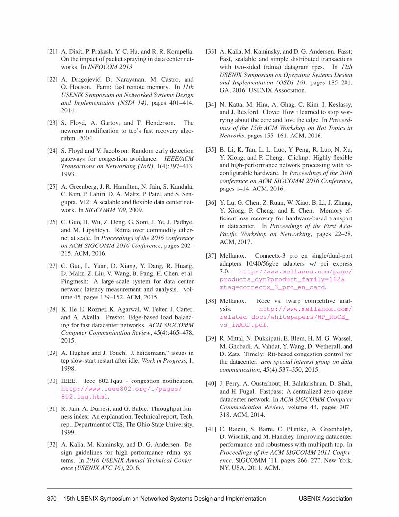
with a rate-shaper, it is quite hard to find flowlets. To val-
idate this, we study the flowlet characteristics of RDMA
and compare it with TCP on our testbed. We measure the
size of flowlets with various inactive intervals. For each
experiment, we run 8 RDMA/TCP flows with size 2GB.
Fig. 20 shows that it is really difficult to observe flowlets
in RDMA traffic. When the inactive interval is larger
than 2μs, the flowlet size is strictly 2GB. In contrast,
TCP does have flowlets. When we set the inactive gap
to 100μs, we observe many flowlets with size ∼60KB.
We conclude that flowlet-based load balancing schemes
may not work well for RDMA traffic. A recent work [47]
reports that flowlet can be used to do load balance for
DCQCN traffic. This might be true for applications with
an on-off traffic pattern, but not for applications that are
throughput intensive. Moreover, as flowlets cannot guar-
antee out-of-order free, it’s not clear how out-of-order
RDMA packets would impact the performance in [47].
Multi-path transport: MPTCP modifies TCP to en-
able multi-path transmission [16,17,41]. The core idea is
to split the original transport into several sub-flows and
distribute packets among these sub-flows according to
their congestion states. Thereby MPTCP adds additional
states proportional to the number of sub-flows and ex-
plores a large re-ordering buffer at the transport layer to
handle out-of-order packets. As aforementioned, this de-
0
0.2
0.4
0.6
0.8
1
10 1K 100K 10M 1G
Frac
tion
of d
ata
byte
s
Flowlet size (bytes)
100 us500 us
(a) TCP.
0
0.2
0.4
0.6
0.8
1
10 1K 100K 10M 1G
Frac
tion
of d
ata
byte
s
Flowlet size (bytes)
0.5 us2 us
(b) RDMA.
Figure 20: Flowlet characteristics in TCP and RDMA.
sign adds considerable memory overhead and is difficult
to implement in hardware.
Generally, the multi-path ACK-clocking of MP-
RDMA resembles the PSLB algorithm [13] in the sense
that both schemes adjust their load on multiple paths in a
per-ACK fashion. However, MP-RDMA independently
adjusts the load on each path while PSLB dynamically
moves the load of slow paths to fast paths.
Recently Mellanox proposed a multi-path support for
RDMA [46]. However, it is just a fail-over solution
using two existing single-path RoCE connections (hot
standby). The goal and the techniques of the Mellanox
multi-path RDMA are completely different from MP-
RDMA, which is a new multi-path RDMA transport.
7 ConclusionThis paper presents MP-RDMA, a multi-path trans-
port for RDMA in datacenters. It can efficiently uti-
lize the rich network paths in datacenters while keep-
ing on-chip memory footprint low. MP-RDMA employs
novel multi-path ACK-clocking and out-of-order awarepath selection to choose best network paths and dis-
tribute packets among them in a congestion-aware man-
ner. In total, MP-RDMA requires only a small constant
(66B) amount of extra memory for each RDMA connec-
tion no matter how many network paths are used. Our
FPGA-based prototype validates the feasibility for MP-
RDMA’s hardware implementation. Our evaluations on
a small-scale testbed as well as large-scale simulation il-
lustrate the effectiveness for MP-RDMA in utilizing the
rich network paths diversity in datacenters.
AcknowledgementsWe thank our shepherd Michael Freedman and the
anonymous reviewers for their valuable comments and
suggestions. We are grateful to Wei Bai, Ran Shu and
Henry Xu for their comments on the modeling. We thank
Larry Luo for his discussion to improve the quality of
the paper. Yun Wang, Wencong Xiao and Sukhan Lee
helped us to improve the writing. This research was par-
tially funded by the National Natural Science Foundation
of China (Grants No. U1605251).
368 15th USENIX Symposium on Networked Systems Design and Implementation USENIX Association
References[1] 802.1Qbb - Priority-based Flow Control.
http://www.ieee802.org/1/pages/802.1bb.html.
[2] Arista 7050x and 7050x2 switch archi-
tecture (a day in the life of a packet).
https://www.arista.com/assets/data/pdf/Whitepapers/Arista_7050X_Switch_Architecture.pdf.
[3] Ns3: A discrete-event network simulator for inter-
net systems. https://www.nsnam.org/.
[4] InfiniBand architecture volume 1, general specifi-cations, release 1.2.1. InfiniBand Trade Associa-
tion, 2008.
[5] InfiniBand architecture volume 2, physical specifi-cations, release 1.3. InfiniBand Trade Association,
2012.
[6] Supplement to InfiniBand architecture specificationvolume 1 release 1.2.2 annex A17: RoCEv2 (IProutable RoCE). InfiniBand Trade Association,
2012.
[7] M. Al-Fares, A. Loukissas, and A. Vahdat. A
scalable, commodity data center network architec-
ture. ACM SIGCOMM Computer CommunicationReview, 38(4):63–74, 2008.
[8] M. Al-Fares, S. Radhakrishnan, B. Raghavan,
N. Huang, and A. Vahdat. Hedera: Dynamic flow
scheduling for data center networks. In Proceed-ings of the 7th USENIX Conference on NetworkedSystems Design and Implementation, NSDI’10,
pages 19–19, Berkeley, CA, USA, 2010. USENIX
Association.
[9] M. Alizadeh, T. Edsall, S. Dharmapurikar,
R. Vaidyanathan, K. Chu, A. Fingerhut, V. T. Lam,
F. Matus, R. Pan, N. Yadav, and G. Varghese.
Conga: Distributed congestion-aware load balanc-
ing for datacenters. In Proceedings of the 2014ACM Conference on SIGCOMM, SIGCOMM ’14,
pages 503–514, New York, NY, USA, 2014. ACM.
[10] M. Alizadeh, A. Greenberg, D. A. Maltz, J. Padhye,
P. Patel, B. Prabhakar, S. Sengupta, and M. Srid-
haran. Data center tcp (dctcp). In Proceedingsof the ACM SIGCOMM 2010 Conference, SIG-
COMM ’10, pages 63–74, New York, NY, USA,
2010. ACM.
[11] M. Alizadeh, A. Javanmard, and B. Prabhakar.
Analysis of dctcp: stability, convergence, and fair-
ness. In Proceedings of the ACM SIGMETRICS
joint international conference on Measurement andmodeling of computer systems, pages 73–84. ACM,
2011.
[12] Altera. Stratix v fpgas. https://www.altera.com/products/fpga/stratix-series/stratix-v/overview.html.
[13] J. Anselmi and N. Walton. Decentralized propor-
tional load balancing. SIAM Journal on AppliedMathematics, 76(1):391–410, 2016.
[14] T. Benson, A. Anand, A. Akella, and M. Zhang.
Microte: Fine grained traffic engineering for data
centers. In Proceedings of the Seventh COnferenceon emerging Networking EXperiments and Tech-nologies, page 8. ACM, 2011.
[15] J. Cao, R. Xia, P. Yang, C. Guo, G. Lu, L. Yuan,
Y. Zheng, H. Wu, Y. Xiong, and D. Maltz. Per-
packet load-balanced, low-latency routing for clos-
based data center networks. In Proceedings ofthe Ninth ACM Conference on Emerging Network-ing Experiments and Technologies, CoNEXT ’13,
pages 49–60, New York, NY, USA, 2013. ACM.
[16] Y. Cao, M. Xu, and X. Fu. Delay-based congestion
control for multipath tcp. In 2012 20th IEEE Inter-national Conference on Network Protocols (ICNP),pages 1–10. IEEE, 2012.
[17] Y. Cao, M. Xu, X. Fu, and E. Dong. Explicit multi-
path congestion control for data center networks.
In Proceedings of the ninth ACM conference onEmerging networking experiments and technolo-gies, pages 73–84. ACM, 2013.
[18] G. Chen, Y. Lu, Y. Meng, B. Li, K. Tan, D. Pei,
P. Cheng, L. L. Luo, Y. Xiong, X. Wang, et al. Fast
and cautious: Leveraging multi-path diversity for
transport loss recovery in data centers. In 2016USENIX Annual Technical Conference (USENIXATC 16). USENIX Association, 2016.
[19] Cisco. Priority flow control: Build reliable layer
2 infrastructure. http://www.cisco.com/en/US/prod/collateral/switches/ps9441/ps9670/white_paper_c11-542809_ns783_Networking_Solutions_White_Paper.html.
[20] B. F. Cooper, A. Silberstein, E. Tam, R. Ramakr-
ishnan, and R. Sears. Benchmarking cloud serving
systems with ycsb. In Proceedings of the 1st ACMsymposium on Cloud computing, pages 143–154.
ACM, 2010.
USENIX Association 15th USENIX Symposium on Networked Systems Design and Implementation 369
[21] A. Dixit, P. Prakash, Y. C. Hu, and R. R. Kompella.
On the impact of packet spraying in data center net-
works. In INFOCOM 2013.
[22] A. Dragojevic, D. Narayanan, M. Castro, and
O. Hodson. Farm: fast remote memory. In 11thUSENIX Symposium on Networked Systems Designand Implementation (NSDI 14), pages 401–414,
2014.
[23] S. Floyd, A. Gurtov, and T. Henderson. The
newreno modification to tcp’s fast recovery algo-
rithm. 2004.
[24] S. Floyd and V. Jacobson. Random early detection
gateways for congestion avoidance. IEEE/ACMTransactions on Networking (ToN), 1(4):397–413,
1993.
[25] A. Greenberg, J. R. Hamilton, N. Jain, S. Kandula,
C. Kim, P. Lahiri, D. A. Maltz, P. Patel, and S. Sen-
gupta. Vl2: A scalable and flexible data center net-
work. In SIGCOMM ’09, 2009.
[26] C. Guo, H. Wu, Z. Deng, G. Soni, J. Ye, J. Padhye,
and M. Lipshteyn. Rdma over commodity ether-
net at scale. In Proceedings of the 2016 conferenceon ACM SIGCOMM 2016 Conference, pages 202–
215. ACM, 2016.
[27] C. Guo, L. Yuan, D. Xiang, Y. Dang, R. Huang,
D. Maltz, Z. Liu, V. Wang, B. Pang, H. Chen, et al.
Pingmesh: A large-scale system for data center
network latency measurement and analysis. vol-
ume 45, pages 139–152. ACM, 2015.
[28] K. He, E. Rozner, K. Agarwal, W. Felter, J. Carter,
and A. Akella. Presto: Edge-based load balanc-
ing for fast datacenter networks. ACM SIGCOMMComputer Communication Review, 45(4):465–478,
2015.
[29] A. Hughes and J. Touch. J. heidemann,” issues in
tcp slow-start restart after idle. Work in Progress, 1,
1998.
[30] IEEE. Ieee 802.1qau - congestion notification.
http://www.ieee802.org/1/pages/802.1au.html.
[31] R. Jain, A. Durresi, and G. Babic. Throughput fair-
ness index: An explanation. Technical report, Tech.
rep., Department of CIS, The Ohio State University,
1999.
[32] A. Kalia, M. Kaminsky, and D. G. Andersen. De-
sign guidelines for high performance rdma sys-
tems. In 2016 USENIX Annual Technical Confer-ence (USENIX ATC 16), 2016.
[33] A. Kalia, M. Kaminsky, and D. G. Andersen. Fasst:
Fast, scalable and simple distributed transactions
with two-sided (rdma) datagram rpcs. In 12thUSENIX Symposium on Operating Systems Designand Implementation (OSDI 16), pages 185–201,
GA, 2016. USENIX Association.
[34] N. Katta, M. Hira, A. Ghag, C. Kim, I. Keslassy,
and J. Rexford. Clove: How i learned to stop wor-
rying about the core and love the edge. In Proceed-ings of the 15th ACM Workshop on Hot Topics inNetworks, pages 155–161. ACM, 2016.
[35] B. Li, K. Tan, L. L. Luo, Y. Peng, R. Luo, N. Xu,
Y. Xiong, and P. Cheng. Clicknp: Highly flexible
and high-performance network processing with re-
configurable hardware. In Proceedings of the 2016conference on ACM SIGCOMM 2016 Conference,
pages 1–14. ACM, 2016.
[36] Y. Lu, G. Chen, Z. Ruan, W. Xiao, B. Li, J. Zhang,
Y. Xiong, P. Cheng, and E. Chen. Memory ef-
ficient loss recovery for hardware-based transport
in datacenter. In Proceedings of the First Asia-Pacific Workshop on Networking, pages 22–28.
ACM, 2017.
[37] Mellanox. Connectx-3 pro en single/dual-port
adapters 10/40/56gbe adapters w/ pci express
3.0. http://www.mellanox.com/page/products_dyn?product_family=162&mtag=connectx_3_pro_en_card.
[38] Mellanox. Roce vs. iwarp competitive anal-
ysis. http://www.mellanox.com/related-docs/whitepapers/WP_RoCE_vs_iWARP.pdf.
[39] R. Mittal, N. Dukkipati, E. Blem, H. M. G. Wassel,
M. Ghobadi, A. Vahdat, Y. Wang, D. Wetherall, and
D. Zats. Timely: Rtt-based congestion control for
the datacenter. acm special interest group on datacommunication, 45(4):537–550, 2015.
[40] J. Perry, A. Ousterhout, H. Balakrishnan, D. Shah,
and H. Fugal. Fastpass: A centralized zero-queue
datacenter network. In ACM SIGCOMM ComputerCommunication Review, volume 44, pages 307–
318. ACM, 2014.
[41] C. Raiciu, S. Barre, C. Pluntke, A. Greenhalgh,
D. Wischik, and M. Handley. Improving datacenter
performance and robustness with multipath tcp. In
Proceedings of the ACM SIGCOMM 2011 Confer-ence, SIGCOMM ’11, pages 266–277, New York,
NY, USA, 2011. ACM.
370 15th USENIX Symposium on Networked Systems Design and Implementation USENIX Association
[42] J. Rasley, B. Stephens, C. Dixon, E. Rozner, W. Fel-
ter, K. Agarwal, J. Carter, and R. Fonseca. Planck:
Millisecond-scale monitoring and control for com-
modity networks. ACM SIGCOMM ComputerCommunication Review, 44(4):407–418, 2015.
[43] L. C. Reference. Linux/include/linux/mlx4/qp.h.
http://lxr.free-electrons.com/source/include/linux/mlx4/qp.h.
[44] A. Roy, H. Zeng, J. Bagga, G. Porter, and A. C.
Snoeren. Inside the social network’s (datacenter)
network. In ACM SIGCOMM Computer Commu-nication Review, volume 45, pages 123–137. ACM,
2015.
[45] A. Singh, J. Ong, A. Agarwal, G. Anderson,
A. Armistead, R. Bannon, S. Boving, G. Desai,
B. Felderman, P. Germano, et al. Jupiter rising: A
decade of clos topologies and centralized control
in google’s datacenter network. ACM SIGCOMMComputer Communication Review, 45(4):183–197,
2015.
[46] M. Technologies. Multi-path rdma.
https://www.openfabrics.org/
images/eventpresos/workshops2015/DevWorkshop/Tuesday/tuesday_04.pdf.
[47] E. Vanini, R. Pan, M. Alizadeh, P. Taheri, and
T. Edsall. Let it flow: Resilient asymmetric load
balancing with flowlet switching. In NSDI, pages
407–420, 2017.
[48] M. Wu, F. Yang, J. Xue, W. Xiao, Y. Miao, L. Wei,
H. Lin, Y. Dai, and L. Zhou. G ra m: scaling graph
computation to the trillions. In Proceedings of theSixth ACM Symposium on Cloud Computing, pages
408–421. ACM, 2015.
[49] Y. Zhu, H. Eran, D. Firestone, C. Guo, M. Lip-
shteyn, Y. Liron, J. Padhye, S. Raindel, M. H.
Yahia, and M. Zhang. Congestion control for large-
scale rdma deployments. In ACM SIGCOMM Com-puter Communication Review, volume 45, pages
523–536. ACM, 2015.
USENIX Association 15th USENIX Symposium on Networked Systems Design and Implementation 371