Embed Size (px)
Citation preview

AMМ-3320 Multi-function LCR
USER`S MANUAL
www.tmatlantic.com

АМM-3320
2
Thank you for purchasing the multi-function LCR from us. Please take a few minutes to browse through this user manual
before you begin to operate the meter to ensure that you are fully familiarized with how best to operate the meter as accurately and safely as possible.
Overview This multi-function LCR is a portable instrument designed with microprocessor control and low power consumption. It
can measure 6 basic parameters: inductance L, capacitance C, AC resistance R, DC resistance DCR, dissipation factor D and quality factor Q. The instrument can easily communicate with PC and realize remote control through USB interface.
With battery external power supply, the meter is ideal for field and portable applications, such as component inspection at fixed place, and immediate measurement by buyer and maintenance personnel. Cautions This instrument can only be used in indoor. Be sure to turn off the instrument when replacing the battery or DC power adapter. Although the instrument has a protection for shocks, inputting dc voltage or current will still damage the instrument. The
capacitance requires completely discharge before measuring. If the instrument is idle for more than three months, please take the batteries out. Use AAA*6 batteries. The instrument cannot work properly when low voltage indication appears. In order to ensure the measurement accuracy, open/short calibration should be carried out again after replacing the test
fixtures. Do not using the instrument under dusty, vibration, direct sunlight and corrosion gas.

АМM-3320
3
Introduction Features 19,999/1,999 counts dual LCD display Basic accuracy: 0.3% with resolution of 0.01% Analog bar display Measurement frequency up to 100kHz Mini-USB interface (USB model only) AutoLCR smart check and measurement Sorting function Relative measurement Data hold Back light, full angle for LCD display 4-terminal measurement configuration Automatic power off Battery and external power supply Battery voltage indication
Specification
Parameter Primary
DCR:DC resistance Ls/Cs:series inductance/capacitance Lp/Cp:parallel inductance/capacitance
Secondary θ:phase angle D:dissipation factor ESR:equivalent series resistance

АМM-3320
4
Q:quality factor Rp:equivalent parallel resistance
Frequency 100/120/1K/10k/100kHz Display Dual display + analog bar display
Measurement range
L
100/120 20mH~20kH 1kHz 2000uH~2000H 10k 200uH~20H 100kHz 20uH~200mH
C
100/120 20nF~20mF 1kHz 2000pF~2mF 10k 200pF~200uF 100kHz 200pF~20uF
R
100/120 200Ω~200MΩ 1kHz 20Ω~200MΩ 10k 20Ω~20MΩ 100kHz 20Ω~2MΩ
DCR 200~200M D/Q 0.001~1999
θ 0.00°~±180.0° Test level 0.6Vrms
Range mode Auto and Hold Equivalent
Circuit Parallel and Series
АМM-3320
5
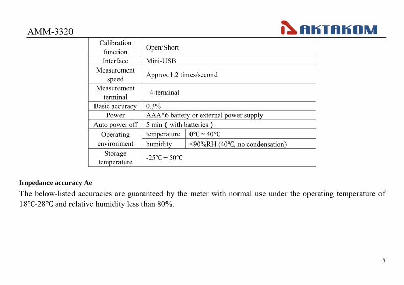
Calibration function Open/Short
Interface Mini-USB Measurement
speed Approx.1.2 times/second
Measurement terminal 4-terminal
Basic accuracy 0.3% Power AAA*6 battery or external power supply
Auto power off 5 min(with batteries) Operating
environment temperature 0~40 humidity ≤90%RH (40, no condensation)
Storage temperature -25~50
Impedance accuracy Ae The below-listed accuracies are guaranteed by the meter with normal use under the operating temperature of 18-28 and relative humidity less than 80%.

АМM-3320
6
Z
Freq. 0.1- 1Ω 1 – 10Ω
10 –
100kΩ
100k –
1MΩ
1M –
20ΜΩ
20Μ−
200MΩ Remark
DCR 1.0%+5d 0.5%+3d 0.3%+2d 0.5%+3d 1.0%+5d 2.0%+5d
D < 0.1 100/
120Hz 1.0%+5d 0.5%+3d 0.3%+2d 0.5%+3d 1.0%+5d 2.0%+5d
1kHz 1.0%+5d 0.5%+3d 0.3%+2d 0.5%+3d 1.0%+5d 5.0%+5d
10kHz 1.0%+5d 0.5%+3d 0.3%+2d 0.5%+3d 2.0%+5d N/A
100kHz 2.0%+5d 1.0%+5d 0.5%+3d 1.0%+5d 2.0%+5d (1M – 2MΩ)
Note: All accuracy is guaranteed by proper ratio resistor calibration and open/short calibration.
If D > 0.1, the accuracy should be multiplied by 21 D+
ZC = fcπ2
1 if D << 0.1 in capacitance mode
ZL = 2πf L if D << 0.1 in inductance mode

АМM-3320
7
Sub-display parameters accuracy: Ae = impedance (Z) accuracy
Definition: Q = D1
Rp = ESR (or Rs)× (1+ )
1. D value accuracy: De = ±Ae × (1+D) 2. ESR accuracy: Re= ±ZM × Ae (Ω)
ie., ZM = impedance calculated by or 2πf L
3. Phase angle θ accuracy: θe= ±(180/π) × Ae (deg) Note: D: dissipation factor
Q: quality factor ESR: equivalent series resistance Rp: equivalent series parallel resistance θ: phase angle

АМM-3320
8
Explanation on Front Panel
Figure 1 The front panel is shown as figure 1. 1. Mini USB interface Connect with PC, easily for data transmission and management. 2. LCD
Used for displaying the measuring results and various symbols. 3. key
Used for putting on or off the operating power for the meter. 4. FUNC. key
When FUNC. key is pressed, the main test mode could be selected sequentially: Auto-LCR mode→Auto-L mode→Auto-C mode→Auto-R mode→DCR mode→ Auto-LCR mode.
5. CAL key Used to do OPEN/SHORT calibration.
6. SORTING key Press this key to enter into sorting mode, which could help the user to make a quick sort for a bunch of components. 7. PCLINK key
Press this key to communicate with PC.

АМM-3320
9
8. HOLD key
Used to maintain the measurement data unchanging, by pressing the key again it will resume the measurement. 9. D/Q/ESR key
In L/C measurement mode, press the key to select parameters of D/Q/θ/ESR. 10. SETUP key When sorting mode is active, press SETUP key to modify the reference value, range and the tolerance settings sequentially. 11. SER/PAL key
Used to select series and parallel mode. 12. FREQ key Press FREQ key to select five different test frequencies in turn: 100/120/1k/10k/100kHz 13. REL% key Press REL% key to enter into relative measurement mode. In auto LCR mode, this key is not available.

АМM-3320
10
14. 4
5
3
key
By pressing this key for once, the backlight of the LCD screen will be opened and after 60 seconds the meter will automatically turn off the backlight. It is also possible to turn off the backlight by pressing this key before the 60 seconds. 15. ENTER key
In sorting mode, press ENTER key to confirm the data modification. 16. Measurement terminal
The instrument has 4-terminal measurement configuration, as shown in figure 2.
Figure 2
INPUTRx Lx Cx
Grounding (shielding)
Excitation positive terminal
Excitation negative terminal
Measurement positive terminalMeasurement negative terminal
GUARD GUARD
L L H HCUR CURPOT POT

АМM-3320
11
Understanding Display Screen
Figure 3 LCD screen is shown as in Figure 3, with its every symbol’s meaning shown as in the Table 1:

АМM-3320
12
NO. Meaning NO. Meaning
1 Auto power off indication 11 Sub-display 2 Data hold 12 Analog bar indication 3 Auto mode indication 13 The Meter is in the data transmission mode. 4 Auto LCR mode indication 14 battery indication (with battery supply) 5 Range indication 15 Frequency indication 6 Relative Measurement mode. 16 Tolerance range 7 Main-display 17 Sorting mode indication 8 Unit for main parameters 18 External power supply 9 Secondary parameters 19 Open/Short calibration mode indication
10 Unit for secondary parameters 20 Primary parameters
Operating instruction Power on the meter
Press key to turn on the power. The default mode is AUTOLCR smart mode and the default test frequency is 1 kHz. When key is pressed during power-on mode, the instrument will enter power-off mode. The LCD will show the “OFF” state before power off.

АМM-3320
13
Function Descriptions 1. Parameters setting Press FUNC. key to select the following parameters sequentially: AUTO LCR, L-Q, C-D, R, DCR.
Parameter Meaning AUTO LCR Auto LCR smart mode
L-Q Inductance measurement,the parameter on sub-display is quality factor Q.
C-D Capacitance measurement, the parameter on sub-display is dissipation factor D.
R Resistance measurement DCR DC resistance measurement mode
L/C/R measurement readings can be positive or negative. In C-D measurement, if the main parameter is "-", the actual component being tested is inductive; In L - Q measurement, if the main parameter is "-", the actual component being tested is capacitive; Theoretically, R is positive, in some cases, R is "-" , which may be calibration error, please re-calibrate the instrument. 2. Auto LCR smart mode
The default test mode is Auto LCR mode which could check the type of impedance smartly. If |θ|<11°, the Auto-R mode is selected. The parameter on sub-display is θ.

АМM-3320
14
If θ > 11°, the Auto-L mode is selected. The parameter on sub-display is Q. If θ < -11°, the Auto-C mode is selected. The parameter on sub-display is D. If the C < 5pF, the parameter on sub-display is parallel resistance Rp. Note: In order to avoid damaging the instrument, the capacitance requires discharge before measuring. 3. Frequency setting Press FREQ key to select frequency value:100/120/1k/10k/100kHz. The LCR impedance scale ranges are depended on the test frequency. 4. Data hold
Press this key to hold the measurement data and press it again to resume the measurement. 5. Relative mode During relative measurement the meter remembers the current readings on primary display(called initial value)when pressing the REL% key, and “REL” symbol appears on LCD. The secondary display will show the percentage of relative value REL%.
The REL% = (present value –initial value) / initial value * 100%. Press REL% key again to show the current readings on primary display and the “REL” symbol will be blinking. The percentage range is from -99.9% ~ 99.9%. When the present value is larger than double of initial value, the “OL%” indication will be shown on the secondary display. During relative measurement, analog bar is always indicating the present measurement value but not the relative value.

АМM-3320
15
6. Open/Short calibration 1)Press CAL key larger than 2 seconds to start the open/short calibration procedure. 2) In open calibration mode, the secondary display will show “Open”. There are two ways for open state input:
a When using square terminals, the square terminals and LCUR/LPOT/HPOT/HCUR terminals hang in the air (shown in figure 4);
b When using LCUR/LPOT/HPOT/HCUR terminals,insert the black and red testing lines with alligator clip into the "LCUR" , "LPOT" terminal and "HCUR" , "HPOT" terminal respectively.(shown in figure 5).
Figure 4 Figure 5
3) Press CAL key and the 30-second countdown will be shown on LCD panels. If the open calibration is finished, the PASS or

АМM-3320
16
FAIL symbol will show on the primary display. Press CAL key again to save the calibration data and enter into the short calibration mode. 4) In short calibration mode, the secondary display will show “Srt”. There are two ways for short state input:
a When using square terminals, insert the short socket to the square terminals and make LCUR/LPOT/HPOT/HCUR terminals hang in the air (shown in figure 6);
b When using LCUR/LPOT/HPOT/HCUR terminals,insert the black and red testing lines with alligator clip into the "LCUR" , "LPOT" terminal and "HCUR" , "HPOT" terminal respectively. Connect the mouth of clips. (shown in figure 7).
Figure 6 Figure 7 5) Press CAL key and the 30-second countdown will be shown on LCD panels. If the short calibration is finished, the PASS or

АМM-3320
17
FAIL symbol will show on the primary display. Press CAL key again to save the calibration data. Note: 1. To get the better accuracy, the open/short calibration should be done before measurement.
2. The purpose of open/short calibration is to reduce the parasitic effect of the test fixture. 3. Open or short circuit, is selected automatically according to the measurement terminal. 4. In short calibration, there may be FAIL situations, which may be caused by not using the low resistance short line or
unreliable contact, please try again after reliable short-circuit 7. Equivalent Circuit When any L/C/R functional mode is selected, the default measurement in series or parallel mode is auto selected and the AUTO segment will be shown on LCD display. It depends on the total equivalent impedance measured. If the impedance is larger than 10kΩ, parallel mode is set and Lp/Cp/Rp is shown on the display. If it is less than 10kΩ, series mode is set and Ls/Cs/Rs is shown on the display. When SEL/PAL key is pressed, the impedance measurement will be set in series mode or in parallel mode sequentially. Note: The actual capacitance, inductance and resistance is not ideal component of pure reactance and pure resistance. Usually the resistance and reactance exist simultaneously. A practical impedance can be simulate by the ideal resistors and ideal reactor (inductor or capacitor) in series or parallel form. 8. Sorting mode The sorting mode could help the user to make a quick sort for a bunch of components. The setting steps as following:

АМM-3320
18
1) According to the component type, press FUNC. key to select L, C or R measurement mode. 2) Insert the standard component into the input terminal. Press SORTING key to enter into the sorting mode and the
"Sorting" symbol appears on LCD. If the LCD reading is OL or less than 200 counts, the SORTING key is not available. 3) When sorting mode is active, press SETUP key to modify the range, reference value and the tolerance settings
sequentially. 4) "Range" symbol is flashing when setting the range. Press D/Q/ESR(←)key to shift the decimal point, unit to left and press
SER/PAL(→) key to right. Press ENTER key to confirm and enter into the reference value setting mode automatically. At this time, "Range" symbol disappear.
5) When setting the reference value, press D/Q/ESR(←)key and SER/PAL(→)key to shift the bit to left and right respectively. Press PCLINK(↑)key and REL%(↓)key to make the digit +1 or -1. The flashing bit is the current setting bit. The reference value setting is available from 20 to 1999 counts. Press ENTER key to confirm and enter into the tolerance setting mode automatically.
6) When setting the tolerance, press D/Q/ESR(←)key and SER/PAL(→)key to select tolerance range: ±0.25% →±0.5% →±1% →±2% →±5% →±10% →±20% →±80%-20%. The default tolerance is +1%. Press ENTER key to confirm.
7) After setting the parameters, remove the standard component and insert the component to be measured. If the impedance measured does not exceed tolerance range, the primary display will show “PASS” , otherwise show “FAIL”. The current measurement result will be shown on the secondary display.
8) Press SORTING key again to exit the sorting mode. Note: In AUTO LCR mode, the SORTING key is not available.

АМM-3320
19
9. PC-LINK mode Press PCLINK key and USB symbol appears on LCD. Connect the instrument to PC through USB interface, and the
measured data can be recorded, analyzed, processed and printed by PC. Press PCLINK key again to cancel the data transmission. Then USB symbol disappears.
Due to the power consumption in data transmission, please extinguish USB display when there is no need to transmit data. Operating step 1. Inductance measurement 1) Turn on the power. 2) There are two ways for inductance input:
a. Insert the measured inductance into the input terminal directly (shown in figure 8); b. Connect the alligator clips to the ends of the measured inductance (shown in figure 9).
3) The default test mode is Auto LCR mode, the inductance value will show on primary display and the quality factor Q will show on secondary display. In Auto LCR mode, the D/Q/ESR key, SEL/PAL key, SORTING key and REL% key are not available.
4) Press FUNC. key to select Auto-L mode. The primary LCD display will show the inductance value. The secondary LCD display will show the quality factor Q. The equivalent resistance ESR/Rp, phase angle θ or dissipation factor D can also be shown by pressing the D/Q/ESR key.
5) Press FREQ key to select frequency value: 100/120/1k/10k/100kHz. 6) Press SER/PAL key to select series or parallel mode.

АМM-3320
20
Figure 8 Figure 9 2. Capacitance measurement 1) Turn on the power. 2) If exists voltage in the capacity, connect the two ends of the capacitor for a short time to discharge. 3) There are two ways for capacitance input:
a. Insert the positive polarity of capacitance into the positive terminal and its negative polarity into the negative terminal (shown in figure 10);
b. Insert the black and red testing lines with alligator clip into the "LCUR", "LPOT" terminal and "HCUR", "HPOT" terminal respectively. Connect the alligator clips to the two ends of capacitance corresponding to its polarity (shown in figure 11).
4)The default test mode is Auto LCR mode, the capacitance value will show on primary display and the dissipation factor D will show on secondary display. In Auto LCR mode, the D/Q/ESR key, SEL/PAL key, SORTING key and REL% key

АМM-3320
21
are not available. 5)Press FUNC. key twice to select Auto-C mode. The primary LCD display will show the capacitance value. The secondary
LCD display will show the dissipation factor D. The quality factor Q, equivalent resistance ESR/Rp or phase angle θ can also be shown by pressing the D/Q/ESR key.
6)Press FREQ key to select frequency value: 100/120/1k/10k/100kHz. 7)Press SER/PAL key to select series or parallel mode. Note: 1. When Auto-LCR mode is active, the secondary parameter will show the equivalent resistance in parallel mode (Rp) to
replace the D factor if the C measured value is less than 5pF. 2. In order to avoid damaging the instrument, the capacitance requires discharge before measuring.
Figure 10 Figure 11

АМM-3320
22
3. Resistance measurement 1) Turn on the power. 2)There are two ways for resistance input:
a. Insert the measured resistance into the input terminal directly (shown in figure 12); b. Connect the alligator clips to the ends of the measured resistance (shown in figure 13).
3)The default test mode is Auto LCR mode, the resistance value will show on primary display and the phase angle θ will show on secondary display. In Auto LCR mode, the D/Q/ESR key, SEL/PAL key, SORTING key and REL% key are not available.
4)Press FUNC. key three times to select Auto-R (ACR) mode. The primary LCD display will show the resistance value. The secondary parameter is omitted and the D/Q/ESR key is not available.
5)Press FREQ key to select frequency value: 100/120/1K/10k/100kHz. 6)Press SER/PAL key to select series or parallel mode. 7)Press FUNC. key four times to select DCR mode. The primary LCD display will show the resistance value. The secondary
parameter is omitted and the D/Q/ESR key, SEL/PAL key and FREQ key are not available. Note: The phase angle θ will show on secondary display only in Auto-LCR mode. During Auto-R mode or DCR mode, the secondary parameter is not available.

АМM-3320
23
Figure 12 Figure 13 To use Adapter (Under external power adapter, the automatic power off function is not available.) Connecting the power adapter: 1,Connect the AC power cord to the AC-DC converter. 2,Plug the AC power cord into an electrical outlet (100V-240V). 3,Plug the DC power plug of the converter into DC power socket of the meter.

АМM-3320
24
AC/DC adapter information: Input:100V-240VAC, 50-60Hz 1.8A Output: DC 12V 2A MAX
Polarity:
WARNING: 1. Please use the original AC power adapter, using other AC power adapter may damage your instrument. 2. The AC power adapter can only be used indoors. 3. Please plug the AC power cord into an electrical outlet first and then firmly insert DC plug into DC input end in the right of
the meter. When unplugged, firstly pull out the DC plug perpendicular to DC input end and then unplug the AC plug from the electrical outlet.
4. Do not use the AC power adapter in other equipment except this instrument. 5. In use, it is a normal phenomenon that the AC power adapter will be hot. 6. Do not demolish the AC power adapter. Otherwise, it may be dangerous. 7. Do not use the AC power adapter in a high temperature or wet place.
DC power socket AC-DC
converter.
DC power plug
AC power cord

АМM-3320
25
8. Please make the AC power adapter avoid a strong bump. 9. It is normal when the AC power adapter make some noise in use. Maintenance Cleaning Periodically wipe the case with a damp cloth and detergent; do not use abrasives or solvents. Calibration Calibrate your instrument once a year to ensure that it performs according to its specifications. Replacing the Battery
Please change the battery when the battery symbol is less than one segment. Turn off the power of the instrument. When you change the battery, and screw off the breechblock on the battery cabinet cover, then take off it and instead the fresh battery.
Accessories User's manual One piece AAA batteries Six pieces Shielding clip line One piece Kelvin 4-terminal measure line One piece Short socket One piece Open socket One piece USB line (USB model only) One piece PC-Link software CD (USB model only) One piece

АМM-3320
26
If there are some changes in accessories, please refer to the real product as standard. Note: To get the better accuracy, when using LCUR/LPOT/HPOT/HCUR terminals measured with the alligator clip-testing lines, Please insert the open socket to the square terminals (shown in figure 14).
Figure 14