Embed Size (px)
Citation preview
ALC5640-VB
Multi-Channel Audio Hub/CODEC and
SounzRealTM
Digital Sound Effect
for Mobile Devices
Datasheet
Rev. 0.91
Realtek Semiconductor Corp.
No. 2, Innovation Road II, Hsinchu Science Park, Hsinchu 300, Taiwan
Tel.: +886-3-578-0211. Fax: +886-3-577-6047
www.realtek.com

ALC5640-VB
Datasheet
Multi-Channel Audio Hub/CODEC and SounzRealTM
Digital Sound Effect for Mobile Devices
ii Rev. 0.91
COPYRIGHT
© 2013 Realtek Semiconductor Corp. All rights reserved. No part of this document may be reproduced,
transmitted, transcribed, stored in a retrieval system, or translated into any language in any form or by any
means without the written permission of Realtek Semiconductor Corp.
DISCLAIMER
Realtek provides this document “as is”, without warranty of any kind. Realtek may make improvements
and/or changes in this document or in the product described in this document at any time. This document
could include technical inaccuracies or typographical errors.
TRADEMARKS
Realtek is a trademark of Realtek Semiconductor Corporation. Other names mentioned in this document
are trademarks/registered trademarks of their respective owners.
USING THIS DOCUMENT
This document is intended for the hardware and software engineer’s general information on the Realtek
ALC5640 Audio Codec IC.
Though every effort has been made to ensure that this document is current and accurate, more
information may have become available subsequent to the production of this guide.
ALC5640-VB
Datasheet
Multi-Channel Audio Hub/CODEC and SounzRealTM
Digital Sound Effect for Mobile Devices
iii Rev. 0.91
REVISION HISTORY Revision Release Date Summary
0.9 2013/4/15 ALC5640-VB first release
0.91 2013/11/27 Add pin function description
ALC5640-VB
Datasheet
Multi-Channel Audio Hub/CODEC and SounzRealTM
Digital Sound Effect for Mobile Devices
iv Rev. 0.91
Table of Contents
1. GENERAL DESCRIPTION .............................................................................................................................................. 1
2. FEATURES ......................................................................................................................................................................... 2
3. SYSTEM APPLICATION ................................................................................................................................................. 3
4. FUNCTION BLOCK AND MIXER PATH ..................................................................................................................... 4
4.1. FUNCTION BLOCK ........................................................................................................................................................ 4 4.2. AUDIO MIXER PATH..................................................................................................................................................... 5 4.3. DIGITAL MIXER PATH .................................................................................................................................................. 6
5. PIN ASSIGNMENTS ......................................................................................................................................................... 7
6. PIN DESCRIPTIONS......................................................................................................................................................... 8
6.1. DIGITAL I/O PINS ......................................................................................................................................................... 8 6.2. ANALOG I/O PINS ........................................................................................................................................................ 9 6.3. FILTER/REFERENCE .................................................................................................................................................... 10 6.4. POWER/GROUND ........................................................................................................................................................ 10
7. FUNCTION DESCRIPTION .......................................................................................................................................... 11
7.1. POWER ....................................................................................................................................................................... 11 7.2. POWER SUPPLY ON/OFF SEQUENCE ........................................................................................................................... 12 7.3. RESET ........................................................................................................................................................................ 15
7.3.1. Power-On Reset (POR) ........................................................................................................................................ 15 7.3.2. Software Reset ...................................................................................................................................................... 15
7.4. CLOCKING .................................................................................................................................................................. 16 7.4.1. Phase-Locked Loop .............................................................................................................................................. 17 7.4.2. I
2C and Two I
2S/PCM Interface ........................................................................................................................... 18
7.5. DIGITAL DATA INTERFACE ........................................................................................................................................ 22 7.5.1. Two I
2S/PCM Interface ......................................................................................................................................... 22
7.6. AUDIO DATA PATH .................................................................................................................................................... 25 7.6.1. 2 Analog ADCs with 4-Channel Record Path ...................................................................................................... 25 7.6.2. 4 DACs with 4-Channel Playback Path................................................................................................................ 26 7.6.3. Mixers ................................................................................................................................................................... 27
7.7. ANALOG AUDIO INPUT PORT ..................................................................................................................................... 28 7.8. ANALOG AUDIO OUTPUT PORT .................................................................................................................................. 29 7.9. MULTI-FUNCTION PINS .............................................................................................................................................. 31 7.10. DRC AND AGC FUNCTION ........................................................................................................................................ 33 7.11. SPEAKER AMPLIFIER RATIO GAIN .............................................................................................................................. 36 7.12. SOUNZREAL SOUND EFFECT ...................................................................................................................................... 37 7.13. EQUALIZER BLOCK .................................................................................................................................................... 37 7.14. WIND FILTER WITH DYNAMIC WIND NOISE DETECTOR ............................................................................................. 37
7.14.1. Wind Filter ....................................................................................................................................................... 37 7.14.2. Dynamic Wind Noise Detector ........................................................................................................................ 40
7.15. I2C CONTROL INTERFACE .......................................................................................................................................... 41
7.15.1. Address Setting ................................................................................................................................................ 41 7.15.2. Complete Data Transfer .................................................................................................................................. 41
7.16. GPIO, INTERRUPT AND JACK DETECTION .................................................................................................................. 43 7.17. POWER MANAGEMENT ............................................................................................................................................... 46 7.18. SMART NOISE CANCELLATION FUNCTION (SNC) ...................................................................................................... 47
ALC5640-VB
Datasheet
Multi-Channel Audio Hub/CODEC and SounzRealTM
Digital Sound Effect for Mobile Devices
v Rev. 0.91
7.19. PROGRAMMABLE REGISTER ARRAY .......................................................................................................................... 48
8. REGISTERS LIST ........................................................................................................................................................... 49
8.1. REGISTER MAP .......................................................................................................................................................... 49 8.2. MX-00H: S/W RESET & DEVICE ID ........................................................................................................................... 52 8.3. MX-01H: SPEAKER OUTPUT CONTROL ...................................................................................................................... 52 8.4. MX-02H: HEADPHONE OUTPUT CONTROL................................................................................................................. 53 8.5. MX-03H: LINE OUTPUT CONTROL ........................................................................................................................... 55 8.6. MX-04H: MONO OUTPUT CONTROL ........................................................................................................................ 56 8.7. MX-0DH: IN1 INPUT CONTROL ................................................................................................................................. 57 8.8. MX-0EH: IN2 INPUT CONTROL ................................................................................................................................. 58 8.9. MX-0FH: INL & INR VOLUME CONTROL ................................................................................................................. 58 8.10. MX-19H: DACL1/R1 DIGITAL VOLUME ................................................................................................................... 59 8.11. MX-1AH: DACL2/R2 DIGITAL VOLUME .................................................................................................................. 60 8.12. MX-1BH: DACL2/R2 MUTE/UN-MUTE CONTROL ................................................................................................... 62 8.13. MX-1CH: STEREO ADC DIGITAL VOLUME CONTROL ............................................................................................... 62 8.14. MX-1DH: MONO ADC DIGITAL VOLUME CONTROL ................................................................................................. 63 8.15. MX-1EH: ADC DIGITAL BOOST GAIN CONTROL ...................................................................................................... 64 8.16. MX-27H: STEREO ADC DIGITAL MIXER CONTROL ................................................................................................... 65 8.17. MX-28H: MONO ADC DIGITAL MIXER CONTROL ..................................................................................................... 65 8.18. MX-29H: STEREO ADC TO DAC DIGITAL MIXER CONTROL ..................................................................................... 66 8.19. MX-2AH: STEREO DAC DIGITAL MIXER CONTROL .................................................................................................. 67 8.20. MX-2BH: MONO DAC DIGITAL MIXER CONTROL .................................................................................................... 67 8.21. MX-2CH: DAC DIGITAL MIXER CONTROL ............................................................................................................... 68 8.22. MX-2FH: INTERFACE DAC/ADC DATA CONTROL .................................................................................................... 69 8.23. MX-3BH: RECMIXL CONTROL 1 ............................................................................................................................. 70 8.24. MX-3CH: RECMIXL CONTROL 2 ............................................................................................................................. 71 8.25. MX-3DH: RECMIXR CONTROL 1 ............................................................................................................................. 72 8.26. MX-3EH: RECMIXR CONTROL 2 ............................................................................................................................. 72 8.27. MX-45H: HPOMIX CONTROL ................................................................................................................................... 73 8.28. MX-46H: SPKMIXL CONTROL ................................................................................................................................. 74 8.29. MX-47H: SPKMIXR CONTROL ................................................................................................................................. 75 8.30. MX-48H: SPOLMIX CONTROL ................................................................................................................................. 76 8.31. MX-49H: SPORMIX CONTROL ................................................................................................................................. 76 8.32. MX-4AH: SPOL/RMIX GAIN CONTROL ................................................................................................................... 77 8.33. MX-4CH: MONOMIX CONTROL .............................................................................................................................. 77 8.34. MX-4DH: OUTMIXL CONTROL 1 ............................................................................................................................ 78 8.35. MX-4EH: OUTMIXL CONTROL 2 ............................................................................................................................. 79 8.36. MX-4FH: OUTMIXL CONTROL 3 ............................................................................................................................. 79 8.37. MX-50H: OUTMIXR CONTROL 1 ............................................................................................................................. 80 8.38. MX-51H: OUTMIXR CONTROL 2 ............................................................................................................................. 81 8.39. MX-52H: OUTMIXR CONTROL 3 ............................................................................................................................. 82 8.40. MX-53H: LOUTMIX CONTROL ................................................................................................................................ 83 8.41. MX-61H: POWER MANAGEMENT CONTROL 1 ............................................................................................................ 83 8.42. MX-62H: POWER MANAGEMENT CONTROL 2 ............................................................................................................ 84 8.43. MX-63H: POWER MANAGEMENT CONTROL 3 ............................................................................................................ 85 8.44. MX-64H: POWER MANAGEMENT CONTROL 4 ............................................................................................................ 86 8.45. MX-65H: POWER MANAGEMENT CONTROL 5 ............................................................................................................ 86 8.46. MX-66H: POWER MANAGEMENT CONTROL 6 ............................................................................................................ 87 8.47. MX-6AH: PRIVATE REGISTER INDEX......................................................................................................................... 88 8.48. MX-6CH: PRIVATE REGISTER DATA.......................................................................................................................... 88 8.49. MX-70H: I2S1 DIGITAL INTERFACE CONTROL .......................................................................................................... 89 8.50. MX-71H: I2S2 DIGITAL INTERFACE CONTROL .......................................................................................................... 90 8.51. MX-73H: ADC/DAC CLOCK CONTROL 1 .................................................................................................................. 91 8.52. MX-74H: ADC/DAC CLOCK CONTROL 2 .................................................................................................................. 92

ALC5640-VB
Datasheet
Multi-Channel Audio Hub/CODEC and SounzRealTM
Digital Sound Effect for Mobile Devices
vi Rev. 0.91
8.53. MX-75H: DIGITAL MICROPHONE CONTROL .............................................................................................................. 92 8.54. MX-80H: GLOBAL CLOCK CONTROL ......................................................................................................................... 93 8.55. MX-81H: PLL CONTROL 1 ......................................................................................................................................... 93 8.56. MX-82H: PLL CONTROL 2 ......................................................................................................................................... 94 8.57. MX-83H: ASRC CONTROL 1 ..................................................................................................................................... 94 8.58. MX-84H: ASRC CONTROL 2 ..................................................................................................................................... 95 8.59. MX-85H: ASRC CONTROL 3 ..................................................................................................................................... 96 8.60. MX-89H: ASRC CONTROL 4 ..................................................................................................................................... 96 8.61. MX-8AH: ASRC CONTROL 5 .................................................................................................................................... 97 8.62. MX-8CH: CLASS-D AMP OC CONTROL ..................................................................................................................... 97 8.63. MX-8DH: CLASS-D AMP OUTPUT CONTROL ............................................................................................................. 98 8.64. MX-8EH: HP AMP CONTROL 1 .................................................................................................................................. 98 8.65. MX-8FH: HP AMP CONTROL 2 .................................................................................................................................. 99 8.66. MX-91H: HP AMP CONTROL ..................................................................................................................................... 99 8.67. MX-92H: SPKVDD DETECTION CONTROL ............................................................................................................. 100 8.68. MX-93H: MICBIAS CONTROL ................................................................................................................................ 100 8.69. MX-B0H: EQ CONTROL 1 ........................................................................................................................................ 101 8.70. MX-B1H: EQ CONTROL 2 ........................................................................................................................................ 102 8.71. MX-B4H: DRC/AGC CONTROL 1 ........................................................................................................................... 103 8.72. MX-B5H: DRC/AGC CONTROL 2 ........................................................................................................................... 104 8.73. MX-B6H: DRC/AGC CONTROL 3 ........................................................................................................................... 106 8.74. MX-BBH: JACK DETECTION CONTROL 1 ................................................................................................................. 107 8.75. MX-BCH: JACK DETECTION CONTROL 2 ................................................................................................................. 108 8.76. MX-BDH: IRQ CONTROL 1 ..................................................................................................................................... 108 8.77. MX-BEH: IRQ CONTROL 2 ...................................................................................................................................... 109 8.78. MX-BFH: GPIO AND INTERNAL STATUS ................................................................................................................. 109 8.79. MX-C0H: GPIO CONTROL 1 .................................................................................................................................... 110 8.80. MX-C2H: GPIO CONTROL 2 .................................................................................................................................... 110 8.81. MX-C8H: PROGRAMMABLE REGISTER ARRAY CONTROL 1 ..................................................................................... 111 8.82. MX-C9H: PROGRAMMABLE REGISTER ARRAY CONTROL 2 ..................................................................................... 111 8.83. MX-CAH: PROGRAMMABLE REGISTER ARRAY CONTROL 3 .................................................................................... 112 8.84. MX-CBH: PROGRAMMABLE REGISTER ARRAY CONTROL 4 .................................................................................... 112 8.85. MX-CCH: PROGRAMMABLE REGISTER ARRAY CONTROL 5 .................................................................................... 112 8.86. MX-CFH: SOUNZREAL BASSBACK CONTROL ......................................................................................................... 113 8.87. MX-D0H: SOUNZREAL TRUTREBLE CONTROL 1 ..................................................................................................... 113 8.88. MX-D1H: SOUNZREAL TRUTREBLE CONTROL 2 ..................................................................................................... 114 8.89. MX-D2H: SOUNZREAL OMNIHEADPHONE CONTROL .............................................................................................. 115 8.90. MX-D3H: WIND FILTER CONTROL – ENABLE/DISABLE .......................................................................................... 115 8.91. MX-D6H:HP AMP CONTROL ................................................................................................................................... 116 8.92. MX-D9H: SOFT VOLUME & ZCD CONTROL ............................................................................................................ 116 8.93. MX-FAH: GENERAL CONTROL 1 ............................................................................................................................. 117 8.94. MX-FBH: GENERAL CONTROL 2 ............................................................................................................................. 118 8.95. PR-3DH: ADC/DAC RESET CONTROL .................................................................................................................. 119 8.96. PR-63H: SOUNZREAL OMNISOUND CONTROL ......................................................................................................... 119 8.97. PR-6CH: WIND DETECTOR CONTROL 1 ................................................................................................................... 120 8.98. PR-6DH: WIND DETECTOR CONTROL 2 ................................................................................................................... 120 8.99. PR-6EH: WIND DETECTOR CONTROL 3 ................................................................................................................... 121 8.100. PR-6FH: WIND DETECTOR CONTROL 4 ............................................................................................................... 121 8.101. PR-70H: WIND DETECTOR CONTROL 5 ............................................................................................................... 121 8.102. PR-73H: WIND DETECTOR CONTROL 6 ............................................................................................................... 121 8.103. PR-75H: SOUNZREAL DIPOLE SPEAKER CONTROL ............................................................................................. 122 8.104. PR-A0H: EQ LOW PASS FILTER COEFFICIENT (LPF:A1) ..................................................................................... 122 8.105. PR-A1H: EQ LOW PASS FILTER GAIN (LPF:H0) ................................................................................................ 122 8.106. PR-A2H: EQ BAND 1 COEFFICIENT (BPF1:A1) ................................................................................................... 123 8.107. PR-A3H: EQ BAND 1 COEFFICIENT (BPF1:A2) ................................................................................................... 123
ALC5640-VB
Datasheet
Multi-Channel Audio Hub/CODEC and SounzRealTM
Digital Sound Effect for Mobile Devices
vii Rev. 0.91
8.108. PR-A4H: EQ BAND 1 GAIN (BPF1:H0) .............................................................................................................. 123 8.109. PR-A5H: EQ BAND 2 COEFFICIENT (BPF2:A1) ................................................................................................... 123 8.110. PR-A6H: EQ BAND 2 COEFFICIENT (BPF2:A2) ................................................................................................... 124 8.111. PR-A7H: EQ BAND 2 GAIN (BPF2:H0) .............................................................................................................. 124 8.112. PR-A8H: EQ BAND 3 COEFFICIENT (BPF3:A1) ................................................................................................... 124 8.113. PR-A9H: EQ BAND 3 COEFFICIENT (BPF3:A2) ................................................................................................... 124 8.114. PR-AAH: EQ BAND 3 GAIN (BPF3:H0) .............................................................................................................. 125 8.115. PR-ABH: EQ BAND 4 COEFFICIENT (BPF4:A1) .................................................................................................. 125 8.116. PR-ACH: EQ BAND 4 COEFFICIENT (BPF4:A2) .................................................................................................. 125 8.117. PR-ADH: EQ BAND 4 GAIN (BPF4:H0) .............................................................................................................. 125 8.118. PR-AEH: EQ HIGH PASS FILTER 1 COEFFICIENT (HPF1:A1) .............................................................................. 126 8.119. PR-AFH: EQ HIGH PASS FILTER 1 GAIN (HPF1:H0) .......................................................................................... 126 8.120. PR-B0H: EQ HIGH PASS FILTER 2 COEFFICIENT (HPF2:A1) ............................................................................... 126 8.121. PR-B1H: EQ HIGH PASS FILTER 2 COEFFICIENT (HPF2:A2) ............................................................................... 126 8.122. PR-B2H: EQ HIGH PASS FILTER 2 GAIN (HPF2:H0) ........................................................................................... 127 8.123. MX-FEH: VENDOR ID ........................................................................................................................................ 127
9. ELECTRICAL CHARACTERISTICS ........................................................................................................................ 128
9.1. DC CHARACTERISTICS ............................................................................................................................................. 128 9.1.1. Absolute Maximum Ratings ................................................................................................................................ 128 9.1.2. Recommended Operating Conditions ................................................................................................................. 128 9.1.3. Static Characteristics ......................................................................................................................................... 128
9.2. ANALOG PERFORMANCE CHARACTERISTICS ............................................................................................................ 129 9.3. SIGNAL TIMING ........................................................................................................................................................ 131
9.3.1. I2C Control Interface .......................................................................................................................................... 131
9.3.2. I2S/PCM Interface Master Mode ........................................................................................................................ 132
9.3.3. I2S/PCM Interface Slave Mode ........................................................................................................................... 133
9.3.4. Digital Microphone Interface ............................................................................................................................. 134
10. APPLICATION CIRCUITS ..................................................................................................................................... 135
11. PACKAGE INFORMATION ................................................................................................................................... 137
11.1. MECHANICAL DIMENSIONS ...................................................................................................................................... 137 11.2. PACKAGE THERMAL INFORMATION ......................................................................................................................... 138
12. ORDERING INFORMATION ................................................................................................................................. 139

ALC5640-VB
Datasheet
Multi-Channel Audio Hub/CODEC and SounzRealTM
Digital Sound Effect for Mobile Devices
viii Rev. 0.91
List of Tables TABLE 1. DIGITAL I/O PINS .......................................................................................................................................................... 8 TABLE 2. ANALOG I/O PINS .......................................................................................................................................................... 9 TABLE 3. FILTER/REFERENCE ..................................................................................................................................................... 10 TABLE 4. POWER/GROUND ......................................................................................................................................................... 10 TABLE 5. POWER SUPPLY FOR BEST PERFORMANCE ................................................................................................................... 11 TABLE 6. POWER SUPPLY CONDITION FOR POWER DOWN LEAKAGE .......................................................................................... 11 TABLE 7. RESET OPERATION ...................................................................................................................................................... 15 TABLE 8. POWER-ON RESET VOLTAGE....................................................................................................................................... 15 TABLE 10. CLOCK SETTING TABLE FOR 48K (UNIT: MHZ) ........................................................................................................ 17 TABLE 11. CLOCK SETTING TABLE FOR 44.1K (UNIT: MHZ) ..................................................................................................... 17 TABLE 12. THE RELATIVE OF SYSCLK/BCLK/LRCK ............................................................................................................... 18 TABLE 13. REGISTER SETTINGS FOR ASRC FUNCTION ON MASTER MODE ................................................................................ 19 TABLE 14. REGISTER SETTINGS FOR ASRC FUNCTION ON SLAVE MODE ................................................................................... 21 TABLE 15. RATION GAIN TABLE FOR SPKVDD AND AVDD ..................................................................................................... 36 TABLE 16. SAMPLE RATE WITH FILTER COEFFICIENT FOR WIND FILTER ..................................................................................... 38 TABLE 17. ADDRESS SETTING (0X38H) ...................................................................................................................................... 41 TABLE 18. WRITE WORD PROTOCOL ........................................................................................................................................ 42 TABLE 19. READ WORD PROTOCOL .......................................................................................................................................... 42 TABLE 20. PROGRAMMABLE REGISTER TABLE ........................................................................................................................... 48 TABLE 21. REGISTER MAP .......................................................................................................................................................... 49 TABLE 22. MX-00H: S/W RESET & DEVICE ID .......................................................................................................................... 52 TABLE 23. MX-01H: SPEAKER OUTPUT CONTROL ..................................................................................................................... 52 TABLE 24. MX-02H: HEADPHONE OUTPUT CONTROL ................................................................................................................ 53 TABLE 25. MX-03H: LINE OUTPUT CONTROL ........................................................................................................................... 55 TABLE 26. MX-04H: MONO OUTPUT CONTROL ........................................................................................................................ 56 TABLE 27. MX-0DH: IN1 INPUT CONTROL ................................................................................................................................ 57 TABLE 28. MX-0EH: IN2 INPUT CONTROL ................................................................................................................................. 58 TABLE 29. MX-0FH: INL & INR VOLUME CONTROL................................................................................................................. 58 TABLE 30. MX-19H: DACL1/R1 DIGITAL VOLUME .................................................................................................................. 59 TABLE 31. MX-1AH: DACL2/R2 DIGITAL VOLUME.................................................................................................................. 60 TABLE 32. MX-1BH: DACL2/R2 MUTE/UN-MUTE CONTROL ................................................................................................... 62 TABLE 33. MX-1CH: STEREO ADC DIGITAL VOLUME CONTROL .............................................................................................. 62 TABLE 34. MX-1DH: MONO ADC DIGITAL VOLUME CONTROL ................................................................................................ 63 TABLE 35. MX-1EH: ADC DIGITAL BOOST GAIN CONTROL ...................................................................................................... 64 TABLE 36. MX-27H: STEREO ADC DIGITAL MIXER CONTROL .................................................................................................. 65 TABLE 37. MX-28H: MONO ADC DIGITAL MIXER CONTROL .................................................................................................... 65 TABLE 38. MX-29H: STEREO ADC TO DAC DIGITAL MIXER CONTROL .................................................................................... 66 TABLE 39. MX-2AH: STEREO DAC DIGITAL MIXER CONTROL ................................................................................................. 67 TABLE 40. MX-2BH: MONO DAC DIGITAL MIXER CONTROL .................................................................................................... 67 TABLE 41. MX-2CH: DAC DIGITAL MIXER CONTROL ............................................................................................................... 68 TABLE 42. MX-2FH: INTERFACE DAC/ADC DATA CONTROL ................................................................................................... 69 TABLE 43. MX-3BH: RECMIXL CONTROL 1 ............................................................................................................................ 70 TABLE 44. MX-3CH: RECMIXL CONTROL 2 ............................................................................................................................ 71 TABLE 45. MX-3DH: RECMIXR CONTROL 1 ............................................................................................................................ 72 TABLE 46. MX-3EH: RECMIXR CONTROL 2 ............................................................................................................................ 72 TABLE 47. MX-45H: HPOMIX CONTROL .................................................................................................................................. 73 TABLE 48. MX-46H: SPKMIXL CONTROL ................................................................................................................................ 74 TABLE 49. MX-47H: SPKMIXR CONTROL ................................................................................................................................ 75 TABLE 50. MX-48H: SPOLMIX CONTROL ................................................................................................................................ 76 TABLE 51. MX-49H: SPORMIX CONTROL ................................................................................................................................ 76 TABLE 52. MX-4AH: SPOL/RMIX GAIN CONTROL .................................................................................................................. 77

ALC5640-VB
Datasheet
Multi-Channel Audio Hub/CODEC and SounzRealTM
Digital Sound Effect for Mobile Devices
ix Rev. 0.91
TABLE 53. MX-4CH: MONOMIX CONTROL ............................................................................................................................. 77 TABLE 54. MX-4DH: OUTMIXL CONTROL 1 ............................................................................................................................ 78 TABLE 55. MX-4EH: OUTMIXL CONTROL 2 ............................................................................................................................ 79 TABLE 56. MX-4FH: OUTMIXL CONTROL 3 ............................................................................................................................ 79 TABLE 57. MX-50H: OUTMIXR CONTROL 1 ............................................................................................................................ 80 TABLE 58. MX-51H: OUTMIXR CONTROL 2 ............................................................................................................................ 81 TABLE 59. MX-52H: OUTMIXR CONTROL 3 ............................................................................................................................ 82 TABLE 60. MX-53H: LOUTMIX CONTROL ............................................................................................................................... 83 TABLE 61. MX-61H: POWER MANAGEMENT CONTROL 1 ........................................................................................................... 83 TABLE 62. MX-62H: POWER MANAGEMENT CONTROL 2 ........................................................................................................... 84 TABLE 63. MX-63H: POWER MANAGEMENT CONTROL 3 ........................................................................................................... 85 TABLE 64. MX-64H: POWER MANAGEMENT CONTROL 4 ........................................................................................................... 86 TABLE 65. MX-65H: POWER MANAGEMENT CONTROL 5 ........................................................................................................... 86 TABLE 66. MX-66H: POWER MANAGEMENT CONTROL 6 ........................................................................................................... 87 TABLE 67. MX-6AH: PRIVATE REGISTER INDEX ........................................................................................................................ 88 TABLE 68. MX-6CH: PRIVATE REGISTER DATA ......................................................................................................................... 88 TABLE 69. MX-70H: I2S1 DIGITAL INTERFACE CONTROL .......................................................................................................... 89 TABLE 70. MX-71H: I2S2 DIGITAL INTERFACE CONTROL .......................................................................................................... 90 TABLE 71. MX-73H: ADC/DAC CLOCK CONTROL 1 ................................................................................................................. 91 TABLE 72. MX-74H: ADC/DAC CLOCK CONTROL 2 ................................................................................................................. 92 TABLE 73. MX-75H: DIGITAL MICROPHONE CONTROL .............................................................................................................. 92 TABLE 74. MX-80H: GLOBAL CLOCK CONTROL ........................................................................................................................ 93 TABLE 75. MX-81H: PLL CONTROL 1 ........................................................................................................................................ 93 TABLE 76. MX-82H: PLL CONTROL 2 ........................................................................................................................................ 94 TABLE 77. MX-83H: ASRC CONTROL 1 ..................................................................................................................................... 94 TABLE 78. MX-84H: ASRC CONTROL 2 ..................................................................................................................................... 95 TABLE 79. MX-85H: ASRC CONTROL 3 ..................................................................................................................................... 96 TABLE 80. MX-89H: ASRC CONTROL 4 ..................................................................................................................................... 96 TABLE 81. MX-8AH: ASRC CONTROL 5 .................................................................................................................................... 97 TABLE 82. MX-8CH: CLASS-D AMP OC CONTROL .................................................................................................................... 97 TABLE 83. MX-8DH: CLASS-D AMP OUTPUT CONTROL ............................................................................................................ 98 TABLE 84. MX-8EH: HP AMP CONTROL 1 ................................................................................................................................. 98 TABLE 85. MX-8FH: HP AMP CONTROL 2 ................................................................................................................................. 99 TABLE 86. MX-91H: HP AMP CONTROL .................................................................................................................................... 99 TABLE 87. MX-92H: SPKVDD DETECTION CONTROL ............................................................................................................. 100 TABLE 88. MX-93H: MICBIAS CONTROL ............................................................................................................................... 100 TABLE 89. MX-B0H: EQ CONTROL 1 ....................................................................................................................................... 101 TABLE 90. MX-B1H: EQ CONTROL 2 ....................................................................................................................................... 102 TABLE 91. MX-B4H: DRC/AGC CONTROL 1 ........................................................................................................................... 103 TABLE 92. MX-B5H: DRC/AGC CONTROL 2 ........................................................................................................................... 104 TABLE 93. MX-B6H: DRC/AGC CONTROL 3 ........................................................................................................................... 106 TABLE 94. MX-BBH: JACK DETECTION CONTROL 1 ................................................................................................................ 107 TABLE 95. MX-BCH: JACK DETECTION CONTROL 2 ................................................................................................................ 108 TABLE 96. MX-BDH: IRQ CONTROL 1 ..................................................................................................................................... 108 TABLE 97. MX-BEH: IRQ CONTROL 2 ..................................................................................................................................... 109 TABLE 98. MX-BFH: GPIO AND INTERNAL STATUS ................................................................................................................ 109 TABLE 99. MX-C0H: GPIO CONTROL 1 ................................................................................................................................... 110 TABLE 100. MX-C2H: GPIO CONTROL 2 ................................................................................................................................. 110 TABLE 101. MX-C8H: PROGRAMMABLE REGISTER ARRAY CONTROL 1 .................................................................................. 111 TABLE 102. MX-C9H: PROGRAMMABLE REGISTER ARRAY CONTROL 2 .................................................................................. 111 TABLE 103. MX-CAH: PROGRAMMABLE REGISTER ARRAY CONTROL 3 ................................................................................. 112 TABLE 104. MX-CBH: PROGRAMMABLE REGISTER ARRAY CONTROL 4.................................................................................. 112 TABLE 105. MX-CCH: PROGRAMMABLE REGISTER ARRAY CONTROL 5.................................................................................. 112 TABLE 106. MX-CFH: SOUNZREAL BASSBACK CONTROL ...................................................................................................... 113 TABLE 107. MX-D0H: SOUNZREAL TRUTREBLE CONTROL 1 .................................................................................................. 113

ALC5640-VB
Datasheet
Multi-Channel Audio Hub/CODEC and SounzRealTM
Digital Sound Effect for Mobile Devices
x Rev. 0.91
TABLE 108. MX-D1H: SOUNZREAL TRUTREBLE CONTROL 2 .................................................................................................. 114 TABLE 109. MX-D2H: SOUNZREAL OMNIHEADPHONE CONTROL ........................................................................................... 115 TABLE 110. MX-D3H: WIND FILTER CONTROL – ENABLE/DISABLE ........................................................................................ 115 TABLE 111. MX-D6H: HP AMP CONTROL ................................................................................................................................ 116 TABLE 112. MX-D9H: SOFT VOLUME & ZCD CONTROL ......................................................................................................... 116 TABLE 113. MX-FAH: GENERAL CONTROL 1 ........................................................................................................................... 117 TABLE 114. MX-FBH: GENERAL CONTROL 2 ........................................................................................................................... 118 TABLE 115. PR-3AH: DIGITAL IO DRIVING CONTROL ............................................................................................................. 119 TABLE 116. PR-3DH: ADC/DAC RESET CONTROL ................................................................................................................ 119 TABLE 117. PR-63H: SOUNZREAL OMNISOUND CONTROL ...................................................................................................... 119 TABLE 118. PR-6CH: WIND DETECTOR CONTROL 1 ................................................................................................................. 120 TABLE 119. PR-6DH: WIND DETECTOR CONTROL 2 ................................................................................................................ 120 TABLE 120. PR-6EH: WIND DETECTOR CONTROL 3 ................................................................................................................. 121 TABLE 121. PR-6FH: WIND DETECTOR CONTROL 4 ................................................................................................................. 121 TABLE 122. PR-70H: WIND DETECTOR CONTROL 5 ................................................................................................................. 121 TABLE 123. PR-73H: WIND DETECTOR CONTROL 6 ................................................................................................................. 121 TABLE 124. PR-75H: SOUNZREAL DIPOLE SPEAKER CONTROL................................................................................................ 122 TABLE 125. PR-A0H: EQ LOW PASS FILTER COEFFICIENT (LPF:A1) ....................................................................................... 122 TABLE 126. PR-A1H: EQ LOW PASS FILTER GAIN (LPF:H0) ................................................................................................... 122 TABLE 127. PR-A2H: EQ BAND 1 COEFFICIENT (BPF1:A1) ..................................................................................................... 123 TABLE 128. PR-A3H: EQ BAND 1 COEFFICIENT (BPF1:A2) ..................................................................................................... 123 TABLE 129. PR-A4H: EQ BAND 1 GAIN (BPF1:H0) ................................................................................................................. 123 TABLE 130. PR-A5H: EQ BAND 2 COEFFICIENT (BPF2:A1) ..................................................................................................... 123 TABLE 131. PR-A6H: EQ BAND 2 COEFFICIENT (BPF2:A2) ..................................................................................................... 124 TABLE 132. PR-A7H: EQ BAND 2 GAIN (BPF2:H0) ................................................................................................................. 124 TABLE 133. PR-A8H: EQ BAND 3 COEFFICIENT (BPF3:A1) ..................................................................................................... 124 TABLE 134. PR-A9H: EQ BAND 3 COEFFICIENT (BPF3:A2) ..................................................................................................... 124 TABLE 135. PR-AAH: EQ BAND 3 GAIN (BPF3:H0) ................................................................................................................ 125 TABLE 136. PR-ABH: EQ BAND 4 COEFFICIENT (BPF4:A1) .................................................................................................... 125 TABLE 137. PR-ACH: EQ BAND 4 COEFFICIENT (BPF4:A2) .................................................................................................... 125 TABLE 138. PR-ADH: EQ BAND 4 GAIN (BPF4:H0) ................................................................................................................ 125 TABLE 139. PR-AEH: EQ HIGH PASS FILTER 1 COEFFICIENT (HPF1:A1) ................................................................................ 126 TABLE 140. PR-AFH: EQ HIGH PASS FILTER 1 GAIN (HPF1:H0) ............................................................................................ 126 TABLE 141. PR-B0H: EQ HIGH PASS FILTER 2 COEFFICIENT (HPF2:A1) ................................................................................. 126 TABLE 142. PR-B1H: EQ HIGH PASS FILTER 2 COEFFICIENT (HPF2:A2) ................................................................................. 126 TABLE 143. PR-B2H: EQ HIGH PASS FILTER 2 GAIN (HPF2:H0) ............................................................................................. 127 TABLE 144. MX-FEH: VENDOR ID ........................................................................................................................................... 127 TABLE 145. ABSOLUTE MAXIMUM RATINGS ............................................................................................................................ 128 TABLE 146. RECOMMENDED OPERATING CONDITIONS............................................................................................................. 128 TABLE 147. STATIC CHARACTERISTICS .................................................................................................................................... 128 TABLE 148. ANALOG PERFORMANCE CHARACTERISTICS ......................................................................................................... 129 TABLE 149. I
2C TIMING ............................................................................................................................................................ 131
TABLE 150. TIMING OF I2S/PCM MASTER MODE ..................................................................................................................... 132
TABLE 151. I2S/PCM SLAVE MODE TIMING ............................................................................................................................. 133
TABLE 152. DIGITAL MICROPHONE INTERFACE TIMING ........................................................................................................... 134 TABLE 153. THERMAL INFORMATION ....................................................................................................................................... 138 TABLE 154. ORDERING INFORMATION ...................................................................................................................................... 139
ALC5640-VB
Datasheet
Multi-Channel Audio Hub/CODEC and SounzRealTM
Digital Sound Effect for Mobile Devices
xi Rev. 0.91
List of Figures FIGURE 1. BLOCK DIAGRAM ....................................................................................................................................................... 4 FIGURE 2. AUDIO MIXER PATH ................................................................................................................................................... 5 FIGURE 3. DIGITAL MIXER PATH ................................................................................................................................................ 6 FIGURE 4. PIN ASSIGNMENTS ...................................................................................................................................................... 7 FIGURE 5. POWER ON/OFF SEQUENCE ...................................................................................................................................... 14 FIGURE 6. AUDIO CLOCK TREE ................................................................................................................................................. 16 FIGURE 7. SYSTEM CONNECTION FOR ASRC FUNCTION ........................................................................................................... 20 FIGURE 8. PCM MONO DATA MODE A FORMAT (BCLK POLARITY=0) .............................................................................. 22 FIGURE 9. PCM MONO DATA MODE A FORMAT (BCLK POLARITY=1) .............................................................................. 22 FIGURE 10. PCM MONO DATA MODE B FORMAT (BCLK POLARITY=0) ............................................................................ 23 FIGURE 11. PCM STEREO DATA MODE A FORMAT (BCLK POLARITY=0) ............................................................................ 23 FIGURE 12. PCM STEREO DATA MODE B FORMAT (BCLK POLARITY=0) .............................................................................. 23 FIGURE 13. I
2S DATA FORMAT (BCLK POLARITY=0) ............................................................................................................. 24
FIGURE 14. LEFT-JUSTIFIED DATA FORMAT (BCLK POLARITY=0) ........................................................................................ 24 FIGURE 15. 4-CHANNEL RECORDING PATH ................................................................................................................................ 25 FIGURE 16. 4-CHANNEL PLAYBACK PATH .................................................................................................................................. 26 FIGURE 17. SPEAKER OUTPUT MODE – STEREO MODE ............................................................................................................... 29 FIGURE 18. DAC DRC FUNCTION BLOCK .................................................................................................................................. 33 FIGURE 19. ADC AGC FUNCTION BLOCK .................................................................................................................................. 33 FIGURE 20. DRC/AGC FOR PLAYBACK/RECORDING MODE ....................................................................................................... 34 FIGURE 21. DRC/AGC FOR NOISE GATE MODE ......................................................................................................................... 35 FIGURE 22. RATIO GAIN BEHAVIOR FOR SPKVDD AND AVDD ................................................................................................ 36 FIGURE 23. WIND NOISE DETECTOR ........................................................................................................................................... 40 FIGURE 24. DATA TRANSFER OVER I
2C CONTROL INTERFACE ................................................................................................... 41
FIGURE 26. GPIO FUNCTION BLOCK .......................................................................................................................................... 43 FIGURE 27. IRQ FUNCTION BLOCK ............................................................................................................................................. 44 FIGURE 27. JD SOURCE SELECTION ............................................................................................................................................ 45 FIGURE 28. POWER MANAGEMENT ............................................................................................................................................. 46 FIGURE 29. SNC FUNCTION DIAGRAM ....................................................................................................................................... 47 FIGURE 30. SNC FUNCTION BLOCK ............................................................................................................................................ 47 FIGURE 31. I
2C CONTROL INTERFACE ....................................................................................................................................... 131
FIGURE 32. TIMING OF I2S/PCM MASTER MODE ...................................................................................................................... 132
FIGURE 33. I2S/PCM SLAVE MODE TIMING ............................................................................................................................. 133
FIGURE 34. DIGITAL MICROPHONE INTERFACE TIMING ............................................................................................................ 134 FIGURE 35. APPLICATION CIRCUIT ........................................................................................................................................... 136 FIGURE 36. PACKAGE DIMENSION ............................................................................................................................................ 137

ALC5640-VB
Datasheet
Multi-Channel Audio Hub/CODEC and SounzRealTM
Digital Sound Effect for Mobile Devices
1 Rev. 0.91
1. General Description The ALC5640 is a high performance, low power, dual I
2S interface audio CODEC. Dual I
2S interface can
connect to different devices and let the ALC5640 to be an Audio Hub. Each device can pass through the
Audio Hub and then perform as input or output application. Asynchronous Sample Rate Converter
(ASRC) provides independent and asynchronous connections to different processors, such as an
application processor, baseband processor or wireless transceiver(BT).
Stereo Class-D speaker amplifiers provide 1.5W per channel into 8Ω or 2.5W per channel into 4Ω with a
5V supply, with excellent PSRR and low EMI. A mono differential earpiece amplifier is also provided,
providing output from any DAC or Analog-in.
The ALC5640 features an ultra low power cap-free headphone amplifier. It consumes only less than
5mW power during playback, providing mobile system longer battery life under headphone listening
mode.
The integrated DRC(Dynamic Range Controller) and 7-band parametric Equalizer provide further digital
sound processing capability of audio playback paths. The DRC in ALC5640 continuously monitors the
DAC output level. When the power level is low, it increases the input signal gain to make it sound louder.
At the same time, if a peaking signal is detected, it autonomously reduces the applied gain to avoid hard
clipping. It ensures the maximum/consistent signal amplitude without producing audio clipping and
speaker damage. The 7-band parametric Equalizer contains 7 independent filters with programmable gain,
center frequency and bandwidth to tailor the frequency characteristics of embedded speaker system
according to user preferences.
For microphone recording, the DRC in ALC5640 can be used as AGC(Auto Gain Controller) to maintain
a constant recording volume. Besides, a dynamic wind reduction filter is built in on recording path. The
filter can detect the level of wind noise and on/off dynamically to keep the recording quality.
SounzRealTM
digital sound effect technology is configurable to provide better listening experience.
OminiSound EXPTM
expands the sound field of embedded stereo speaker. BassBack EXPTM
and TruBass
EXPTM
bring LFE(low frequency effect) to listeners without subwoofer needed. OmniHeadphone EXPTM
provides broader sound field when wearing headphone. TruTreble EXPTM
adds processed harmonic tones
at high frequency, bringing more melody and details for music listening.
ALC5640 only requires two voltage supplies and consume ultra low power, making it ideal for mobile
devices.

ALC5640-VB
Datasheet
Multi-Channel Audio Hub/CODEC and SounzRealTM
Digital Sound Effect for Mobile Devices
2 Rev. 0.91
2. Features Analog Features:
Digital-to-Analog Converter with 100dBA SNR
Analog-to-Digital Converter with 94dBA SNR
Differential analog microphone inputs with boost pre-amplifiers and low noise microphone bias
+20/+24/+30/+35/+40/+44/+50/+52 dB microphone boost gain
MIC input to ADC with 50dB boost gain, SNR > 66dBA and THD+N < -65dB
Adjustable MICBIAS (0.9*MICVDD or 0.75*MICVDD)
Stereo line inputs
Line input to ADC with 0dB gain, SNR >= 94dBA, THD+N <= -83dB
Stereo line outputs
DAC to line output with 0dB gain, SNR >= 100dBA, THD+N <= -86dB
Stereo/Mono BTL (Bridge-Tied-Load) Class-D amplifier
650mW/CH (SPKVDD=3.6V, THD+N < = 1%, 8Ohm Load)
500mW/CH (SPKVDD=3.6V, THD+N < = 0.1%, 8Ohm Load)
1.2W/CH (SPKVDD=5.0V, THD+N < = 1%, 8Ohm Load)
2.5W/CH (SPKVDD=5.0V, THD+N < = 10%, 4Ohm Load)
2.1W/CH (SPKVDD=5.0V, THD+N < = 1%, 4Ohm Load)
Stereo Cap-Free headphone amplifier with ultra low power consumption for playback
20mW/CH (AVDD=CPVDD=1.8V, THD+N <= -80dB, 16/32Ohm Load)
Playback power consumption <= 5mW (AVDD=VBVDD=CPVDD=1.8V, 16Ohm, With I2S
Clock, Playback Silence)
Playback power consumption <= 13mW (AVDD=VBVDD=CPVDD=1.8V, 16Ohm, With I2S
Clock, Playback 1mW/CH)
Mono differential receiver amplifier
50mW/CH (AVDD=CPVDD=1.8V, THD+N <= -70dB, 16Ohm Load, BTL mode)
Audio jack insert/combo jack detection
Inside PLL can receiver wide range clock input

ALC5640-VB
Datasheet
Multi-Channel Audio Hub/CODEC and SounzRealTM
Digital Sound Effect for Mobile Devices
3 Rev. 0.91
Digital Features:
Two 24bit/8kHz ~ 192kHz I2S/PCM interface for each mono DAC and stereo DAC
Two 24bit/8kHz ~ 192kHz I2S/PCM interface for stereo ADC
I2C control interface
Two digital microphone interface support
Asynchronous sample rate converter (ASRC) for each interface
Programmable register table with two sequencers
7-bands flexible equalizer (EQ) for DAC path or ADC path
Enhanced DRC(Dynamic Range Control)/AGC(Auto Gain Control) function for DAC path or ADC
path
Dynamic wind noise reduction filter
Zero detection and soft volume for pop noise suppression
Speaker amplifier DC term self-test function for speaker protection
SounzRealTM
audio sound processing
OmniHeadphone EXPTM
OminiSound EXPTM
TruTreble EXPTM
BassBack EXPTM
TruBass EXPTM
2.1-Ch Generator from 2-Ch Track
Dipole Speaker
3. System Application Smart Phones
Tablet

ALC5640-VB
Datasheet
Multi-Channel Audio Hub/CODEC and SounzRealTM
Digital Sound Effect for Mobile Devices
4 Rev. 0.91
4. Function Block and Mixer Path
4.1. Function Block
AG
ND
DC
VD
D
DG
ND
CPVDD
CPGND
Analog Core
LDO1
Digital Core
Digtial I/O
SP
KV
DD
L
SP
KV
DD
R
SP
KG
ND
DB
VD
D
LDO1_IN
Class-D
Power Stage
LD
O1
_E
N
IN1P
IN1N
MIC
Boost
ADCL
ADCR
Realtek
Audio Sound
Effect
DACL1
DACR1
Output
Mixer
Digital Audio Interface
BC
LK
1L
RC
K1
DA
CD
AT
1A
DC
DA
T1
LOUTL
LOUTR
SPOLP
SPORP
SPOLN
SPORN
SPO_L_Vol
SPO_R_Vol
I2C
Control
SC
L
SD
A
Spike
Filter
Spike
Filter
MICBIAS1
PLL
MC
LK
GP
IO1
/IR
QHPO_L_Vol
HPO_R_Vol
HPOL
HPOR
VREF1
ADC
Volume
High Pass
Filter
DAC
Volume
High Pass
Filter
DM
IC_
SC
L/
GP
IO2
DMIC
Interface
DM
IC1
_S
DA
MICBIAS
Reference
Voltage
IN2P
IN2N
REC
Mixer
MICVDD
AVDD
OUT_Vol
MICBST2
INL
DACL2
BC
LK
2L
RC
K2
DA
CD
AT
2A
DC
DA
T2
MICBST1
INR
VREF2
DACR2
CPP2CPN1
CPVEE
Charge Pump
Headphone
block CPN2
CPP1
CPVPP
MICBIAS1
0.9 * MICVDD
0.75 * MICVDD
MIC
VD
D
LDO2
REG_EN
AVDD
DM
IC2
_S
DA
Volume
MONOP
MONON
DACREF
IN3P
IN3N
Figure 1. Block Diagram

ALC5640-VB
Datasheet
Multi-Channel Audio Hub/CODEC and SounzRealTM
Digital Sound Effect for Mobile Devices
5 Rev. 0.91
4.2. Audio Mixer Path
SPOLMIX
Digital Sound Effect
OUTMIXL
OUTMIXR
Class D AMP
SPOLP
SPOLN
HPOL
HPOR
VOL_SPO_L
(-46.5 ~ +12dB, 1.5dB/step)
VOL_SPO_R
(-46.5 ~ +12dB, 1.5dB/step)
VOL_O_L
(-46.5 ~ +12dB, 1.5dB/step)
VOL_O_R
(-46.5 ~ +12dB, 1.5dB/step)
SPKVOLL
SPKVOLR
OUTVOLR
OUTVOLL
DACL2
LOUTMIX
OUTMIXL
OUTMIXR
RECMIXL
RECMIXR
MICBST1
MICBST2
ADC_R
ADC_L
DAC_L1
DAC_L2
DAC_R1
Fil
ter
&
Dig
ital
Vo
lum
e
AD
CD
AT
1
DA
CD
AT
1
DMIC1/2_DAT
DACL1
DACR1
DACL2
VOL_HPO_L
(-46.5 ~ +12dB, 1.5dB/step)
HPOVOLL
VOL_HPO_R
(-46.5 ~ +12dB, 1.5dB/step)
HPOVOLR
DACR1
Fil
ter
&
Dig
ital
Vo
lum
e
Fil
ter
&
Dig
ital
Vo
lum
eF
ilte
r &
Dig
ital
Vo
lum
e
Fil
ter
&
Dig
ital
Vo
lum
e
SPKMIXL
SPKMIXR
LOUTR
LOUTL
VMID
VMID
IN1N
IN1P
IN2N
IN2P
DACL2
DACR2
OUTMIXL
INL
INR
MICBST1
MICBST2
OUTMIXR
RECMIXL
INL
INL
DACL2
MICBST1
MICBST1
MICBST2
INR
RECMIXR
INR
DACR1
MU_HPO_R
MU_HPO_L
HPOLMIX
MU_SPO_Lmu_spkvoll_in
mu_spkvolr_in
mu_hpovoll_in
mu_hpovolr_in
mu_outvolr_in
mu_outvoll_inMU_LOUT
OUTVOLL
OUTVOLR
SPKVOLL
DACL1
SPORMIX
Class D AMP
SPORP
SPORN
MU_SPO_R
SPKVOLR
0/20/24/30/35/40/44/50/52
0/20/24/30/35/40/44/50/52
MICBST2
MICBST1
MICBST1
MICBST2
AD
CD
AT
2
DA
CD
AT
2
HPOVOLL
HPORMIX
RECMIXL
RECMIXR
Gain
Gain
Gain
Gain
-9 ~ 0dB, 3dB/step
Gain
Gain
Gain
Gain
Gain
-18 ~ 0dB, 3dB/step
Gain
Gain
Gain
Gain
Gain
-18 ~ 0dB, 3dB/step
Gain
Gain
Gain
Gain
-9 ~ 0dB, 3dB/step
Gain
Gain
Gain
Gain
-6 ~ 0dB, 6dB/step
Gain
Gain
Gain
Gain
2.27, 1.58, 0.58, 0, -1.5, -3, -4.5, -6dB
Gain
Gain
Gain
Gain
-6 ~ 0dB, 6dB/step
-6 ~ 0dB, 6dB/step
Gain
Gain
Gain
Gain
Gain
Gain
Gain
Gain
-18 ~ 0dB, 3dB/step
-18 ~ 0dB, 3dB/step
DACR1
SPKVOLR
-34.5~+12dB,1.5dB/step
INL
-34.5~+12dB,1.5dB/step
INR
SPKVOLL
OUTVOLL
OUTVOLR
SPKVOLR
HPOVOLL
HPOVOLR
HPOVOLR
DAC_R2 DACR2
Fil
ter
&
Dig
ital
Vo
lum
e
DACR2
DACL2
DACR1
MICBST1
GainGainDACL1
DACR2Gain
Gain
DACL1Gain
Gain
DACR2Gain
RECMIXL
RECMIXR
Gain
DACL1
MICBST1
GainDACR1
DMIC1_SDA
DMIC2_SDA
MONOMIX
MONON
MONOPMU_MONO
OUTVOLL
OUTVOLR
Gain
Gain
Gain
Gain
-6 ~ 0dB, 6dB/step
MICBST1
GainDACR2
DACL2
DACL1Gain
DACR1Gain
2.27, 1.58, 0.58, 0, -1.5, -3, -4.5, -6dB
MX-0D[15:12]
MX-0D[7]
MX-0E[11:8]
MX-0E[6]
MX-0F[12:8]
MX-0F[4:0]
MX-3B[12:10]
MX-3B[9:7]
MX-3C[15:13]
MX-3C[12:10]
MX-3C[5]
MX-3C[4]
MX-3C[1]
MX-3C[0]
MX-3E[12:10]
MX-3D[9:7]
MX-3E[15:13]
MX-3D[12:10]
MX-3E[0]
MX-3E[4]
MX-3E[1]
MX-3E[5]
MX-45[15]
MX-45[14]
MX-45[13]
MX-45[12]
MX-45[15]
MX-45[14]
MX-45[13]
MX-45[12]
MX-46[15:14]
MX-46[13:12]
MX-46[11:10]
MX-46[9:8]
MX-46[7:6]
MX-46[5]
MX-46[4]
MX-46[3]
MX-46[2]
MX-46[1]
MX-47[7:6]
MX-47[11:10]
MX-47[9:8]
MX-47[13:12]
MX-47[15:14]
MX-47[1]
MX-47[3]
MX-47[2]
MX-47[4]
MX-47[5]
MX-48[11]
MX-48[12]
MX-48[13]
MX-48[14]
MX-48[15]
MX-4A[2:0]
MX-49[11]
MX-49[12]
MX-49[13]MX-4A[2:0]
MX-4C[11]
MX-4C[12]
MX-4C[13]
MX-4C[14]
MX-4C[15]MX-4C[10]
MX-4D[9:7]
MX-4D[6:4]
MX-4D[3:1]
MX-4E[15:13]
MX-4E[12:10]
MX-4E[9:7]
MX-4F[5]
MX-4F[4]
MX-4F[3]
MX-4F[2]
MX-4F[1]
MX-4F[0]
MX-51[9:7]
MX-51[12:10]
MX-51[15:13]
MX-50[3:1]
MX-50[6:4]
MX-50[9:7]
MX-50[15:13]
MX-52[0]
MX-52[1]
MX-52[2]
MX-52[3]
MX-52[4]
MX-52[5]
MX-52[7]
MX-53[15]
MX-53[14]
MX-53[13]
MX-53[12]MX-53[11]
MX-01[15]
MX-01[14]MX-01[13:8]
MX-01[7]
MX-01[6]MX-01[5:0]
MX-02[15]
MX-02[14]MX-02[13:8]
MX-02[7]
MX-02[6]MX-02[5:0]
MX-03[7]MX-03[14]
MX-03[13:8]
MX-03[15]
MX-03[6]MX-03[5:0]
MX-04[15]
I2S1 Pwr Ctrl:
MX-61[15]
I2S2 Pwr Ctrl:
MX-61[14]
DAC_L1 Pwr Ctrl:
MX-61[12]
DAC_R1 Pwr Ctrl:
MX-61[11]
DAC_L2 Pwr Ctrl:
MX-61[7]
DAC_R2 Pwr Ctrl:
MX-61[6]
ADC_L Pwr Ctrl:
MX-61[2]
ADC_L Pwr Ctrl:
MX-61[1]
Class-D Pwr Ctrl:
MX-61[0]
Class-D Pwr Ctrl:
MX-61[0]
ADC Stereo Mixer Pwr Ctrl:
MX-62[15]
ADC Mono L Mixer Pwr Ctrl:
MX-62[14]
ADC Mono R Mixer Pwr Ctrl:
MX-62[13]
LOUTMIX Pwr Ctrl:
MX-63[12]
MONO MIX Pwr Ctrl:
MX-63[10]
MICBST1 Pwr Ctrl:
MX-64[15]
MICBST2 Pwr Ctrl:
MX-64[12]
OUTMIXL Pwr Ctrl:
MX-65[15]
OUTMIXR Pwr Ctrl:
MX-65[14]
SPKMIXL Pwr Ctrl:
MX-65[13]
SPKMIXR Pwr Ctrl:
MX-65[12]
RECMIXL Pwr Ctrl:
MX-65[11]
RECMIXR Pwr Ctrl:
MX-65[10]
SPKVOLL Pwr Ctrl:
MX-66[15]
SPKVOLR Pwr Ctrl:
MX-66[14]
OUTVOLL Pwr Ctrl:
MX-66[13]
OUTVOLR Pwr Ctrl:
MX-66[12]
HPOVOLL Pwr Ctrl:
MX-66[11]
HPOVOLL Pwr Ctrl:
MX-66[10]
INRVOL Pwr Ctrl:
MX-66[8]
INLVOL Pwr Ctrl:
MX-66[9]
MONO Amp Pwr Ctrl:
MX-63[8]
MICBST3
VMID
IN3N
IN3P
0/20/24/30/35/40/44/50/52
MICBST3
MX-0D[11:8]
MX-0D[6]
MICBST3 Pwr Ctrl:
MX-64[14]
MICBST3 Gain
MX-3B[3:1]MX-3C[2]
GainMX-3E[2] MX-3D[3:1]
MICBST3
MICBST3Gain
MX-4D[12:10]MX-4F[6]
MICBST3Gain
MX-50[12:10]MX-52[6]
Figure 2. Audio Mixer Path

ALC5640-VB
Datasheet
Multi-Channel Audio Hub/CODEC and SounzRealTM
Digital Sound Effect for Mobile Devices
6 Rev. 0.91
4.3. Digital Mixer Path
VOL
IF1_DAC_L
IF1_DAC_R
Wind filter
Digital Interface Process
L L
R R
L R
L R
DACL1
DACL2
DACR1
Gain
Gain
Gain
Gain
DAC_MIXL
IF1_A
DC
_L
VOLWind filter
IF1_D
AC
_L
IF1_D
AC
_R
L L
R R
L R
L R
L L
R R
L R
L R
IF2_D
AC
_L
IF2_D
AC
_R
L L
R R
L R
L R
Gain
IF2_A
DC
_L
DACL2
DACR2
DACL2Gain
Gain
IF1_A
DC
_R
IF2_A
DC
_R
DMIC2_R
SNC - II
DACR2DACR2
DACR1
DACL1
DACL1
Gain
Gain
DACR1
Gain
DACL2
Gain
Gain
Realtek SounzReal
Audio Sound Effect
IF2_ADC_L
IF2_ADC_R
IF2_DAC_R
DMIC1_L
DAC_MIXL
DAC_MIXR
Gain
Gain
DAC_MIXR
DACR2
DACL2
DACR2
Stereo_DAC_Mixer_L
Stereo_DAC_Mixer_R
Mono_DAC_Mixer_L
Mono_DAC_Mixer_R
Stereo_ADC_Mixer_L
Stereo_ADC_Mixer_R
DACL1
DACR1
ADCL
ADCR
DMIC2_R
DMIC1_L
Mono_ADC_Mixer_L
Mono_ADC_Mixer_R
Mono_DAC_MIX_L
Mono_DAC_MIX_R
ADC_L
ADC_R
IF2_DAC_L VOL
VOL
VOL
VOL
EQ/ALC
(Share with DAC path)
IF1_ADC_L
IF1_ADC_R
DMIC2_L
DMIC1_R
DMIC2_L
Digital Interface 1 Digital Interface 2
IF1_D
AC
IF1_A
DC
IF2_D
AC
IF2_A
DC
DA
CD
AT
1
AD
CD
AT
1
DA
CD
AT
2
AD
CD
AT
2
IF1_A
DC
IF2_A
DC
IF1_D
AC
IF2_D
AC
DA
CD
AT
2
AD
CD
AT
2
DA
CD
AT
1
AD
CD
AT
1
IF1_A
DC
IF2_A
DC
IF1_D
AC
IF2_D
AC
VOL
VOL
Bass_DAC
DMIC1_R
MX-27[11:10]
MX-27[13]
MX-27[14]
MX-27[12]
MX-27[6]
MX-27[5]
MX-27[12]
MX-27[11:10]
MX-28[11:10]
MX-28[3:2]
MX-28[12]
MX-28[4]
MX-28[13]
MX-28[14]
MX-28[6]
MX-28[5]
MX-1D[14:8]
MX-1D[6:0]
MX-D3 & PR-6E
MX-D3 & PR-6E
MX-1C[14:8]
MX-1C[6:0]
MX-1C[15]
MX-1C[7]
MX-29[15]
MX-29[14]
MX-29[7]
MX-29[6]
MX-19[15:8]
MX-19[7:0]
MX-2E[15:14]
MX-1A[15:8]
MX-1A[7:0]
MX-2A[14]
MX-2A[13]
MX-2A[12]
MX-2A[11]
MX-2A[10]MX-2A[2]
MX-2A[6]
MX-2A[5]
MX-2A[4]
MX-2A[3]
MX-2B[14]
MX-2B[13]MX-2B[12]
MX-2B[11]MX-2B[10]
MX-2B[9]
MX-2B[6]
MX-2B[5]MX-2B[4]
MX-2B[3]MX-2B[2]
MX-2B[1]
MX-2C[15]MX-2C[14]
MX-2C[13]
MX-2C[12]
MX-2C[11]MX-2C[10]
MX-2C[9]
MX-2C[8]MX-2F[15:14] MX-2F[13:12] MX-2F[11:10] MX-2F[9:8]
MX-71[6] MX-71[6]
MX-70[14:12] MX-70[14:12]
DACL2
DACR2
MX-1B[13]
MX-1B[12]
Gain
Gain
MX-1E[15:14]
MX-1E[13:12]
MX-FA[13]
MX-FA[12]
Figure 3. Digital Mixer Path

ALC5640-VB
Datasheet
Multi-Channel Audio Hub/CODEC and SounzRealTM
Digital Sound Effect for Mobile Devices
7 Rev. 0.91
5. Pin Assignments
CPP1
CPVDD
AG
ND
SP
O_L
P
SP
KV
DD
L
LR
CK
1
LDO1_EN
SPO_RP
SPO_RN
LOUTL
SPKVDDR
SPO_LN
LOUTR
MCLK
SCL
SDA
BC
LK
1
AD
CD
AT
2
DA
CD
AT
2
HP
O_L
HP
O_R
CP
VE
E
HP
OF
B
CPN1
1 2 3 4 5 6 7 8 9 10 11 12
36 35 34 33 32 31 30 29 28 27 26 25
13
14
15
16
17
18
19
20
21
22
23
24
48
47
46
45
44
43
42
41
40
39
38
37
xxxxxxx ywwvs(Top View)
IN1N
/DM
IC2_
DA
T/J
D1
IN1P
/DM
IC1
_D
AT
IN2P
IN2N
/JD
2
VR
EF
1
GPIO1/IRQ
DCVDD
DBVDD
ALC5640
BC
LK
2
LR
CK
2
AD
CD
AT
1
DA
CD
AT
1
VR
EF
2
CPVPP
CPGND
CPP2
CPN2
DA
CR
EF
MIC
VD
D
AVDD
MIC
BIA
S1
MONOP/IN3P
MONON/IN3N
GPIO2/DMIC_SCL
Figure 4. Pin Assignments
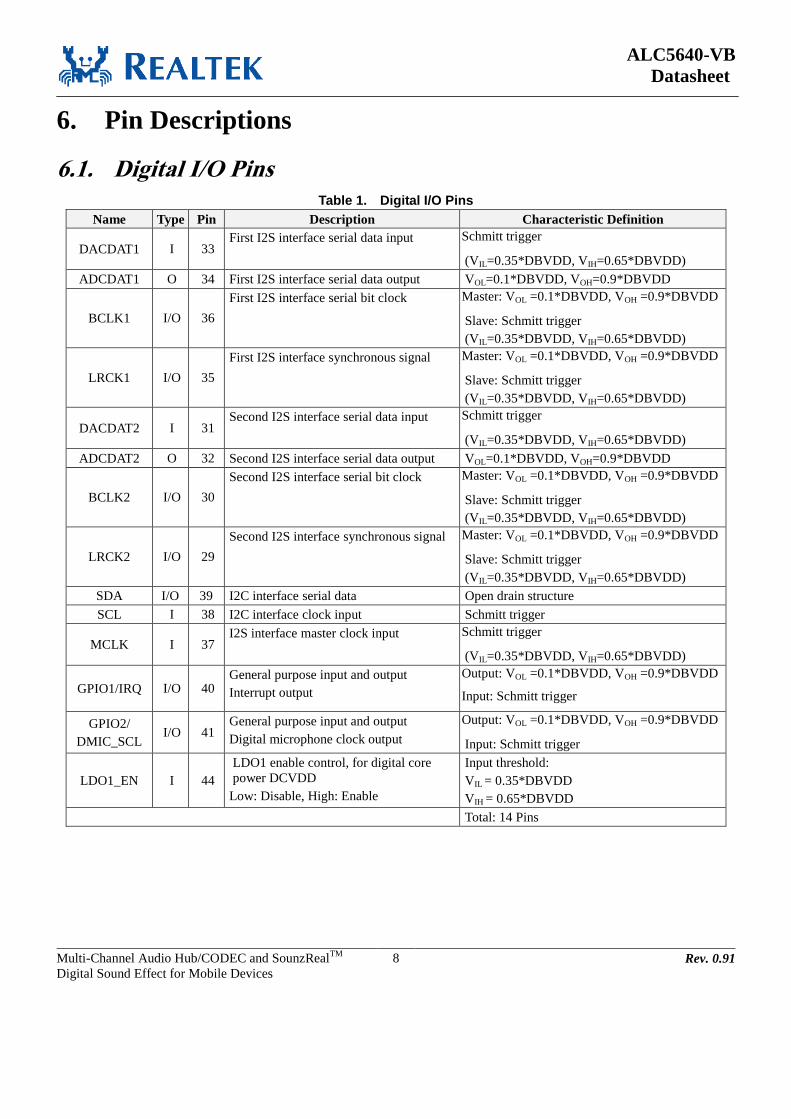
ALC5640-VB
Datasheet
Multi-Channel Audio Hub/CODEC and SounzRealTM
Digital Sound Effect for Mobile Devices
8 Rev. 0.91
6. Pin Descriptions
6.1. Digital I/O Pins
Table 1. Digital I/O Pins
Name Type Pin Description Characteristic Definition
DACDAT1 I 33 First I2S interface serial data input Schmitt trigger
(VIL=0.35*DBVDD, VIH=0.65*DBVDD)
ADCDAT1 O 34 First I2S interface serial data output VOL=0.1*DBVDD, VOH=0.9*DBVDD
BCLK1 I/O 36
First I2S interface serial bit clock Master: VOL =0.1*DBVDD, VOH =0.9*DBVDD
Slave: Schmitt trigger
(VIL=0.35*DBVDD, VIH=0.65*DBVDD)
LRCK1 I/O 35
First I2S interface synchronous signal Master: VOL =0.1*DBVDD, VOH =0.9*DBVDD
Slave: Schmitt trigger
(VIL=0.35*DBVDD, VIH=0.65*DBVDD)
DACDAT2 I 31 Second I2S interface serial data input Schmitt trigger
(VIL=0.35*DBVDD, VIH=0.65*DBVDD)
ADCDAT2 O 32 Second I2S interface serial data output VOL=0.1*DBVDD, VOH=0.9*DBVDD
BCLK2 I/O 30
Second I2S interface serial bit clock Master: VOL =0.1*DBVDD, VOH =0.9*DBVDD
Slave: Schmitt trigger
(VIL=0.35*DBVDD, VIH=0.65*DBVDD)
LRCK2 I/O 29
Second I2S interface synchronous signal Master: VOL =0.1*DBVDD, VOH =0.9*DBVDD
Slave: Schmitt trigger
(VIL=0.35*DBVDD, VIH=0.65*DBVDD)
SDA I/O 39 I2C interface serial data Open drain structure
SCL I 38 I2C interface clock input Schmitt trigger
MCLK I 37 I2S interface master clock input Schmitt trigger
(VIL=0.35*DBVDD, VIH=0.65*DBVDD)
GPIO1/IRQ I/O 40 General purpose input and output
Interrupt output
Output: VOL =0.1*DBVDD, VOH =0.9*DBVDD
Input: Schmitt trigger
GPIO2/
DMIC_SCL I/O 41
General purpose input and output
Digital microphone clock output
Output: VOL =0.1*DBVDD, VOH =0.9*DBVDD
Input: Schmitt trigger
LDO1_EN I 44
LDO1 enable control, for digital core
power DCVDD
Low: Disable, High: Enable
Input threshold:
VIL = 0.35*DBVDD
VIH = 0.65*DBVDD
Total: 14 Pins

ALC5640-VB
Datasheet
Multi-Channel Audio Hub/CODEC and SounzRealTM
Digital Sound Effect for Mobile Devices
9 Rev. 0.91
6.2. Analog I/O Pins
Table 2. Analog I/O Pins
Name Type Pin Description Characteristic Definition
LOUTR O 17 Line output type (single-end output)
Right channel
Analog output
LOUTL O 16 Line output type (single-end output)
Left channel
Analog output
IN2P I 7
Positive differential input for microphone
2
Left channel line input
Analog input
IN2N/JD2 I 8
Negative differential input for
microphone 2
Right channel line input
Second jack detection pin
Analog input
JD threshold: VIL = 0.2V, VIH = 1.2V
IN1P/DMIC1_
DAT I 5
Positive differential input for microphone
1
First digital microphone data input
Analog input
Digital input (Only can accept 1.8V digital
signal input)
IN1N/DMIC2
_DAT/JD1 I 6
Negative differential input for
microphone 1
Second digital microphone data input
First jack detection pin
Analog input
Digital input (Only can accept 1.8V digital
signal input)
JD threshold: VIL = 0.2V, VIH = 1.2V
HPO_R O 26 Headphone amplifier output
Right channel
Analog output
HPO_L O 28 Headphone amplifier output
Left channel
Analog output
SPO_LP O 1 Speaker amplifier output
Left differential positive output channel
Analog output
SPO_LN O 48 Speaker amplifier output
Left differential negative output channel
Analog output
SPO_RP O 45 Speaker amplifier output
Right differential positive output channel
Analog output
SPO_RN O 47 Speaker amplifier output
Right differential negative output channel
Analog output
MONOP/IN3P I/O 13
Mono output with driving capability
Differential positive output channel
Positive differential or single-end input
for microphone 3
Analog output
Analog input
MONON/IN3
N I/O 14
Mono output with driving capability
Differential negative output channel
Negative differential input for
microphone 3
Analog output
Analog input
Total: 14 Pins

ALC5640-VB
Datasheet
Multi-Channel Audio Hub/CODEC and SounzRealTM
Digital Sound Effect for Mobile Devices
10 Rev. 0.91
6.3. Filter/Reference
Table 3. Filter/Reference
Name Type Pin Description Characteristic Definition
MICBIAS1 O 4 Bias voltage output for microphone Programmable analog DC output
VREF1 O 11 First internal reference voltage 4.7uF capacitor to analog ground
VREF2 O 12 Second internal reference voltage 4.7uF capacitor to analog ground
HPOFB - 25 Headphone reference ground Headphone ground
CPN1 - 21 First charge pump bucket capacitor 2.2uf capacitor to CPP1
CPP1 - 20 First charge pump bucket capacitor 2.2uf capacitor to CPN1
CPN2 - 18 Second charge pump bucket capacitor 2.2uf capacitor to CPP2
CPP2 - 19 Second charge pump bucket capacitor 2.2uf capacitor to CPN2
Total: 8 Pins
6.4. Power/Ground
Table 4. Power/Ground
Name Type Pin Description Characteristic Definition
MICVDD P 3 Analog power for MICBIAS 3.0V ~ 3.3V (Default 3.3V is recommended)
AVDD P 15 Analog power for core and I/O 1.71V ~ 1.9V (Default 1.8V is recommended)
DACREF P 10 Analog power 1.71V ~ 1.9V (Default 1.8V is recommended)
AGND P 9 Analog ground
CPVDD P 23 Analog power for headphone charge
pump
1.71V ~ 1.9V (Default 1.8V is recommended)
CPGND P 22 Analog ground for headphone charge
pump
CPVEE P 27 Charge pump negative voltage output 2.2uf capacitor to analog ground
CPVPP P 24 Charge pump positive voltage output 2.2uf capacitor to analog ground
DCVDD P 42
Digital power for digital core.
Kept open if LDO1_EN is pulled high, or
connected to external 1.2V power.
1.1V~1.3V
(Default open is recommended. Pull high
LDO1_EN to DBVDD to general 1.2V
DCVDD by internal LDO. It can be connected
to external 1.2V if LDO1_EN is pulled low.)
LDO1_IN P 23 Supply for DCVDD 1.71V ~ 1.9V (Default 1.8V is recommended)
Powered by CPVDD
DBVDD P 43 Digital power for digital I/O buffer 1.71V~3.3V (Default 1.8V is recommended)
SPKVDDL P 2 Speaker AMP power for left channel 3.0V~5.0V (Default 5V or 3.3V)
SPKVDDR P 46 Speaker AMP power for right channel 3.0V~5.0V (Default 5V or 3.3V)
SPKGND/
DGND P 49*
Speaker AMP ground
Digital ground
Exposed-Pad
Total: 12 Pins
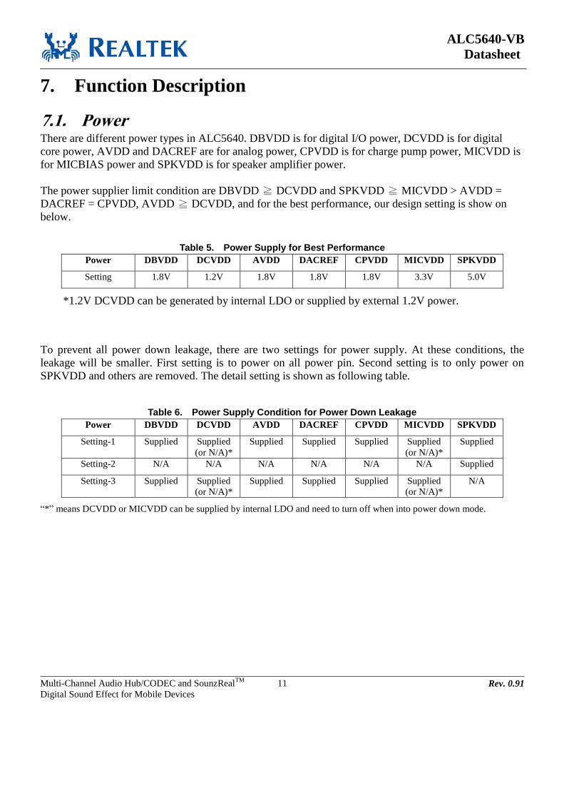
ALC5640-VB
Datasheet
Multi-Channel Audio Hub/CODEC and SounzRealTM
Digital Sound Effect for Mobile Devices
11 Rev. 0.91
7. Function Description
7.1. Power There are different power types in ALC5640. DBVDD is for digital I/O power, DCVDD is for digital
core power, AVDD and DACREF are for analog power, CPVDD is for charge pump power, MICVDD is
for MICBIAS power and SPKVDD is for speaker amplifier power.
The power supplier limit condition are DBVDD ≧ DCVDD and SPKVDD ≧ MICVDD > AVDD =
DACREF = CPVDD, AVDD ≧ DCVDD, and for the best performance, our design setting is show on
below.
Table 5. Power Supply for Best Performance
Power DBVDD DCVDD AVDD DACREF CPVDD MICVDD SPKVDD
Setting 1.8V 1.2V 1.8V 1.8V 1.8V 3.3V 5.0V
*1.2V DCVDD can be generated by internal LDO or supplied by external 1.2V power.
To prevent all power down leakage, there are two settings for power supply. At these conditions, the
leakage will be smaller. First setting is to power on all power pin. Second setting is to only power on
SPKVDD and others are removed. The detail setting is shown as following table.
Table 6. Power Supply Condition for Power Down Leakage
Power DBVDD DCVDD AVDD DACREF CPVDD MICVDD SPKVDD
Setting-1 Supplied Supplied
(or N/A)*
Supplied Supplied Supplied Supplied
(or N/A)*
Supplied
Setting-2 N/A N/A N/A N/A N/A N/A Supplied
Setting-3 Supplied Supplied
(or N/A)*
Supplied Supplied Supplied Supplied
(or N/A)*
N/A
“*” means DCVDD or MICVDD can be supplied by internal LDO and need to turn off when into power down mode.

ALC5640-VB
Datasheet
Multi-Channel Audio Hub/CODEC and SounzRealTM
Digital Sound Effect for Mobile Devices
12 Rev. 0.91
7.2. Power Supply On/Off Sequence
To prevent pop noise and make sure function work normally, following power on and off sequence are
recommended.
Case1: For SPKVDD is from battery:
Power On Sequence: (Sequentially turn on power pins)
1. Pull LDO1_EN pin (Pin#44) to DGND (digital ground)
2. SPKVDD power supply on
3. DCVDD power supply on (This step is required if DCVDD is supplied by external 1.2V power. This
step and step 7 are exclusive.)
4. DBVDD/AVDD/DACREF/CPVDD=1.8V power supply on
5. DBVDD power supply on (This step is required if DBVDD is supplied higher than 1.8V)
6. MICVDD power supply on (This step is required if MICVDD is supplied by external power)
7. Pull LDO1_EN pin (Pin#44) to DBVDD (This step is required if DCVDD is generated by internal
LDO. This step and step 3 are exclusive. If DCVDD is supplied by external 1.2V, LDO1_EN must be
pulled low.)
8. Software starts to initialize ALC5640.
Power Off Sequence: (Sequentially turn off power pins)
1. Power down all Codec function (Write 0x0000’h to register MX-00’h)
2. Pull LDO1_EN pin (Pin#44) to DGND (If internal LDO is used to generate DCVDD)
3. MICVDD power supply off (If MICVDD is supplied by external power)
4. DBVDD power supply off (This step is required if DBVDD is supplied higher than 1.8V)
5. DBVDD/AVDD/DACREF/CPVDD power supply off
6. DCVDD power supply off (If DCVDD is supplied by external power)
7. SPKVDD power supply off

ALC5640-VB
Datasheet
Multi-Channel Audio Hub/CODEC and SounzRealTM
Digital Sound Effect for Mobile Devices
13 Rev. 0.91
Case2: For SPKVDD is from PMIC:
Power On Sequence: (Sequentially turn on power pins)
1. Pull LDO1_EN pin (Pin#44) to DGND (digital ground)
2. DCVDD power supply on (This step is required if DCVDD is supplied by external 1.2V power. This
step and step 7 are exclusive.)
3. DBVDD/AVDD/DACREF/CPVDD=1.8V power supply on
4. DBVDD power supply on (This step is required if DBVDD is supplied higher than 1.8V)
5. MICVDD power supply on (This step is required if MICVDD is supplied by external power)
6. SPKVDD power supply on
7. Pull LDO1_EN pin (Pin#44) to DBVDD (This step is required if DCVDD is generated by internal
LDO. This step and step 2 are exclusive. If DCVDD is supplied by external 1.2V, LDO1_EN must be
pulled low.)
8. Software starts to initialize ALC5640.
Power Off Sequence: (Sequentially turn off power pins)
1. Power down all Codec function (Write 0x0000’h to register MX-00’h)
2. Pull LDO1_EN pin (Pin#44) to DGND (If internal LDO is used to generate DCVDD)
3. SPKVDD power supply off
4. MICVDD power supply off (If MICVDD is supplied by external power)
5. DBVDD power supply on (This step is required if DBVDD is supplied higher than 1.8V)
6. DBVDD/AVDD/DACREF/CPVDD power supply off
7. DCVDD power supply off (If DCVDD is supplied by external power)

ALC5640-VB
Datasheet
Multi-Channel Audio Hub/CODEC and SounzRealTM
Digital Sound Effect for Mobile Devices
14 Rev. 0.91
> 400ms
SPKVDD
DBVDD=AVDD=CPVDD=1.8V
If DBVDD=3.3V
MICVDD=3.3V
Codec Initial
> 200ms
LDO1_EN
Figure 5. Power On/Off Sequence

ALC5640-VB
Datasheet
Multi-Channel Audio Hub/CODEC and SounzRealTM
Digital Sound Effect for Mobile Devices
15 Rev. 0.91
7.3. Reset
There are 2 types of reset operation: power on reset (POR) and register reset.
Table 7. Reset Operation
Reset Type Trigger Condition CODEC Response
POR Monitor digital power supply voltage reach
VPOR
Reset all hardware logic and all registers to default
values.
Register Reset Write MX-00h Reset all registers to default values except some specify
control registers and logic.
7.3.1. Power-On Reset (POR)
When powered on, DCVDD passes through the VPOR band of the ALC5640 (VPOR_ON ~VPOR_OFF). A
power on reset (POR) will generate an internal reset signal (POR reset ‘LOW’) to reset the whole chip.
Table 8. Power-On Reset Voltage
Symbol Min Typical Max Unit
VPOR_ON - 0.8 - V
VPOR_OFF - 0.52 - V
Note:
1.VPOR_OFF must be below VPOR_ON
2. ToC = 25
oC
3. When DCVDD is supplied 1.2V
7.3.2. Software Reset When MX-00h is wrote, all registers become to default value.

ALC5640-VB
Datasheet
Multi-Channel Audio Hub/CODEC and SounzRealTM
Digital Sound Effect for Mobile Devices
16 Rev. 0.91
7.4. Clocking The system clock of ALC5640 can be selected from MCLK or PLL. MCLK is always provided externally
while the reference clock of PLL can be selected from MCLK, BCLK1/2. The driver should arrange the
clock of each block and setup each divider.
The Clk_sys_i2s1=256*Fs provides clocks into stereo DAC/ADC filter that can be selected from MCLK
or PLL. Refer to Figure 5. Audio SYSCLK
The Clk_sys_i2s2=256*Fs provides clocks into mono DAC/ADC filter that can be selected from MCLK,
PLL, refer to Figure 5. Audio SYSCLK
When enable ASRC (Asynchronous Sample Rate Converter) function, the clock sources from MCLK and
BCLK1 (or BCLK2) are allowed to be asynchronous. The Realtek ASRC technology can ensure data
accuracy and keep audio performance under clock source asynchronous.
When ALC5640 at master mode, the clock source from MCLK will be divided and be sent to external
device. The ratio of BCLK and LRCK can set by register – MX-73.
PLL
MCLK
Clk_sys_i2s1(256FS)
(Slave)
LRCK1(Slave)
MCLK
PLL
LRCK2
MX80[15:14]
MX80[13:12]MX80[3]
MX73[14:12]
Stereo DAC
Filter
LRCK1LRCK1(Master)
Master Mode
LRCK/BCLK
Ratio
LRCK2(Slave)
LRCK2(Master)
BCLK2
BCLK1BCLK1(Master)
BCLK2(Master)
div
MX83[15]
DIV_F2Clk_sys_i2s2(256FS)
MX73[10:8]
Inter. Clock
MX89[14:12]
÷2
DIV_F1
Stereo ADC
Filter
Mono DAC
Filter 1
MX89[10:8] MX83[12]MX83[14]
div
1/3
Mono DAC
Filter 2
Mono ADC
Filter 1
Mono ADC
Filter 2
(Slave)
MX70[15]
MX71[15]
MX70[15]
MX71[15]
MX81 & MX82
MX73[15]
ASRC1
ASRC2
Filter_Clk1
Filter_Clk2
Filter_Clk1 (256FS)
Clk_sys_i2s2(256FS) Master Mode
LRCK/BCLK
RatioMX73[11]
Figure 6. Audio Clock Tree
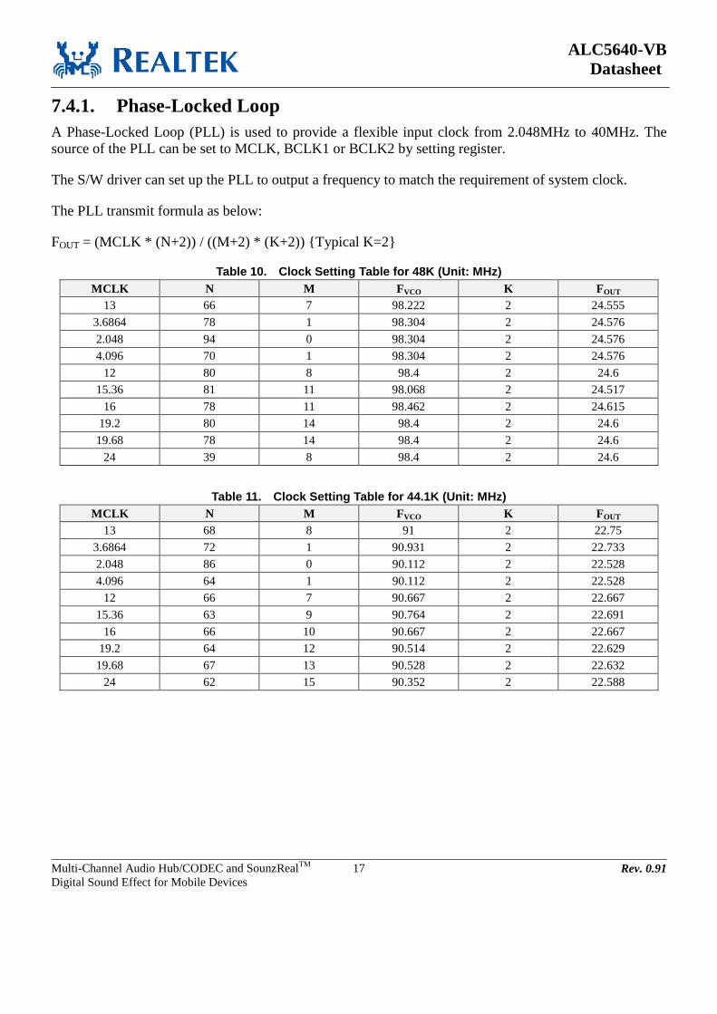
ALC5640-VB
Datasheet
Multi-Channel Audio Hub/CODEC and SounzRealTM
Digital Sound Effect for Mobile Devices
17 Rev. 0.91
7.4.1. Phase-Locked Loop
A Phase-Locked Loop (PLL) is used to provide a flexible input clock from 2.048MHz to 40MHz. The
source of the PLL can be set to MCLK, BCLK1 or BCLK2 by setting register.
The S/W driver can set up the PLL to output a frequency to match the requirement of system clock.
The PLL transmit formula as below:
FOUT = (MCLK * (N+2)) / ((M+2) * (K+2)) {Typical K=2}
Table 10. Clock Setting Table for 48K (Unit: MHz)
MCLK N M FVCO K FOUT
13 66 7 98.222 2 24.555
3.6864 78 1 98.304 2 24.576
2.048 94 0 98.304 2 24.576
4.096 70 1 98.304 2 24.576
12 80 8 98.4 2 24.6
15.36 81 11 98.068 2 24.517
16 78 11 98.462 2 24.615
19.2 80 14 98.4 2 24.6
19.68 78 14 98.4 2 24.6
24 39 8 98.4 2 24.6
Table 11. Clock Setting Table for 44.1K (Unit: MHz)
MCLK N M FVCO K FOUT
13 68 8 91 2 22.75
3.6864 72 1 90.931 2 22.733
2.048 86 0 90.112 2 22.528
4.096 64 1 90.112 2 22.528
12 66 7 90.667 2 22.667
15.36 63 9 90.764 2 22.691
16 66 10 90.667 2 22.667
19.2 64 12 90.514 2 22.629
19.68 67 13 90.528 2 22.632
24 62 15 90.352 2 22.588

ALC5640-VB
Datasheet
Multi-Channel Audio Hub/CODEC and SounzRealTM
Digital Sound Effect for Mobile Devices
18 Rev. 0.91
7.4.2. I2C and Two I
2S/PCM Interface
The ALC5640 supports I2C for the digital control interface, and has two I
2S/PCM for digital data
interface. These two I2S/PCM audio digital interfaces are used to send data to 4 DACs or to receive data
from a stereo ADC. These two I2S/PCM audio digital interfaces can be configured to Master mode or
Slave mode.
Master Mode
Under master mode, BCLK and LRCK are configured as output. If I2S SYSCLK is selected from MCLK
source, sel_sysclk1 (MX-80[15:14]) should set as 00’b. If selected from PLL output, sel_sysclk1 should
set as 01’b. PLL’s source is suggested to provide frequency from 2.048MHz to 40MHz. The driver
should set each divider (MX-73 and MX-89) to arrange the clock distribution. Refer to Figure5. Audio
Clock Tree, for details.
Table 12. The relative of SYSCLK/BCLK/LRCK
Register Settings MCLK BCLK LRCK
MX-73[15]=0’b 256*FS=12.288MHz 32*FS=1.536MHz FS=48KHz
MX-73[15]=1’b 256*FS=12.288MHz 64*FS=3.072MHz FS=48KHz
MX-73[15]=0’b 256*FS=11.2896MHz 32*FS=1.4112MHz FS=44.1KHz
MX-73[15]=1’b 256*FS=11.2896MHz 64*FS=2.8224MHz FS=44.1KHz
Example for master mode:
Target format:
Sample Rate: 48 KHz
Channel Length: 32 bits
LRCK=48KHz
BCLK=3.072MHz (64 * 48KHz)
MCLK clock request:
MCLK=12.288MHz (256 * 48 KHz)
Register settings:
Set MX-FA[0] to “1” // For MCLK input clock getting control
Set MX-61[15] to “1” // Enable I2S-1
Set MX-70[15] to “0” // Enable Master mode
Set MX-73[15] to “1” // Select 64*FS for BCLK in master mode
Set MX-73[14:12] to “000” // Select I2S-1 pre-divider

ALC5640-VB
Datasheet
Multi-Channel Audio Hub/CODEC and SounzRealTM
Digital Sound Effect for Mobile Devices
19 Rev. 0.91
For ASRC function on Codec master mode, the Codec only support it on some conditions. These
conditions are sample rate fix at 48KHz, MCLK fix at 19.2MHz and frame rate fix at 50FS. Some
registers need to set for this mode as shown at Table 13.
Table 13. Register Settings for ASRC Function on Master Mode
Condition:
Codec as Master Mode
MCLK = 19.2MHz
Frame Rate = 50*FS
Target Sample Rate (FS) = 48KHz
Item Register Settings Note
I2S-1 to DAC1 MX-83 = 0x8000’h
MX-84 = 0x0020’h
MX-FB = 0x0004’h
For DAC1 playback ASRC settings
I2S-2 to DAC2 MX-83 = 0x1800’h
MX-84 = 0xC000’h
MX-FB = 0x0002’h
For DAC2 playback ASRC settings
AMIC to Stereo ADC Filter
to I2S-1
MX-83 = 0x8000’h
MX-84 = 0x0800’h
MX-FB = 0x0004’h
For AMIC to Stereo ADC Filter record ASRC settings
AMIC to Mono ADC Filter
to I2S-2
MX-83 = 0x1800’h
MX-84 = 0x3800’h
MX-FA = 0x0731’h
MX-FB = 0x0002’h
For AMIC to Mono ADC Filter record ASRC settings
DMIC1 to Stereo ADC Filter
to I2S-1
MX-83 = 0x8200’h
MX-FB = 0x0004’h
For DMIC1 to Stereo ADC Filter record ASRC settings
DMIC2 to Mono ADC Filter
to I2S-2
MX-83 = 0x1900’h
MX-84 = 0x3800’h
MX-FA = 0x0741’h
MX-FB = 0x0002’h
For DMIC2 to Mono ADC Filter record ASRC settings

ALC5640-VB
Datasheet
Multi-Channel Audio Hub/CODEC and SounzRealTM
Digital Sound Effect for Mobile Devices
20 Rev. 0.91
Slave Mode
Under slave mode BCLK and LRCK are configured as input. The SYSCLK can be input from MCLK,
and BCLK can be synchronous or asynchronous to MCLK. If the SYSCLK is selected from BCLK, the
internal PLL should generate 256*FS by BCLK. And the driver should set each divider to arrange the
clock distribution. Refer to Figure5. Audio Clock Tree, for details.
If an asynchronous MCLK input for BCLK and LRCK, you can turn ASRC function for this situation. As
Figure 6 shown, the MCLK is from external oscillator that clock is no relation (or asynchronous) with
SOC and BT or 3G BaseBand. For the connection for SOC and BT can connect directly to Codec and let
Codec as slave mode and SOC/BT as master mode.
For the clock requirement of MCLK must large than 512*FS as SYSCLK that FS is sample rate. If the
MCLK is smaller than 512*FS, that can use internal PLL to generate higher than 512*FS clock.
Codec
I2S-1 as Slave Mode
With ASRC
I2S-1 as Slave Mode
With ASRC
OSC
MCLK
SOC BT/3G BB
Figure 7. System Connection for ASRC Function
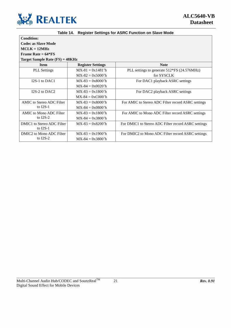
ALC5640-VB
Datasheet
Multi-Channel Audio Hub/CODEC and SounzRealTM
Digital Sound Effect for Mobile Devices
21 Rev. 0.91
Table 14. Register Settings for ASRC Function on Slave Mode
Condition:
Codec as Slave Mode
MCLK = 12MHz
Frame Rate = 64*FS
Target Sample Rate (FS) = 48KHz
Item Register Settings Note
PLL Settings MX-81 = 0x1481’h
MX-82 = 0x5000’h
PLL settings to generate 512*FS (24.576MHz)
for SYSCLK
I2S-1 to DAC1 MX-83 = 0x8000’h
MX-84 = 0x0020’h
For DAC1 playback ASRC settings
I2S-2 to DAC2 MX-83 = 0x1800’h
MX-84 = 0xC000’h
For DAC2 playback ASRC settings
AMIC to Stereo ADC Filter
to I2S-1
MX-83 = 0x8000’h
MX-84 = 0x0800’h
For AMIC to Stereo ADC Filter record ASRC settings
AMIC to Mono ADC Filter
to I2S-2
MX-83 = 0x1800’h
MX-84 = 0x3800’h
For AMIC to Mono ADC Filter record ASRC settings
DMIC1 to Stereo ADC Filter
to I2S-1
MX-83 = 0x8200’h For DMIC1 to Stereo ADC Filter record ASRC settings
DMIC2 to Mono ADC Filter
to I2S-2
MX-83 = 0x1900’h
MX-84 = 0x3800’h
For DMIC2 to Mono ADC Filter record ASRC settings

ALC5640-VB
Datasheet
Multi-Channel Audio Hub/CODEC and SounzRealTM
Digital Sound Effect for Mobile Devices
22 Rev. 0.91
7.5. Digital Data Interface
7.5.1. Two I2S/PCM Interface
The two I2S/PCM interface can be configured as master mode or slave mode. Three audio data formats
are supported:
PCM mode
Left justified mode
I2S mode
1 2 nn-1
LRCK
BLCK
DACDAT/
ADCDAT
1/Fs
MSB LSB
Figure 8. PCM MONO Data Mode A Format (BCLK POLARITY=0)
1 2 nn-1
MSB LSB
1/Fs
LRCK
BLCK
DACDAT/
ADCDAT
Figure 9. PCM MONO Data Mode A Format (BCLK POLARITY=1)
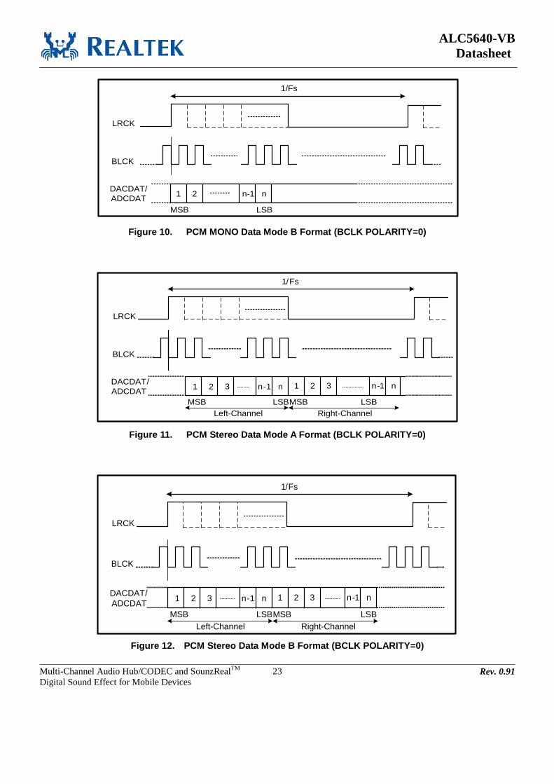
ALC5640-VB
Datasheet
Multi-Channel Audio Hub/CODEC and SounzRealTM
Digital Sound Effect for Mobile Devices
23 Rev. 0.91
1 2 nn-1
LRCK
BLCK
DACDAT/
ADCDAT
1/Fs
MSB LSB
Figure 10. PCM MONO Data Mode B Format (BCLK POLARITY=0)
1 2 3 nn-1
LRCK
BLCK
DACDAT/
ADCDAT
1/Fs
MSB LSB
1 2 3 nn-1
MSB LSB
Left-Channel Right-Channel
Figure 11. PCM Stereo Data Mode A Format (BCLK POLARITY=0)
1 2 3 nn-1
LRCK
BLCK
DACDAT/
ADCDAT
1/Fs
MSB LSB
1 2 3 nn-1
MSB LSB
Left-Channel Right-Channel
Figure 12. PCM Stereo Data Mode B Format (BCLK POLARITY=0)

ALC5640-VB
Datasheet
Multi-Channel Audio Hub/CODEC and SounzRealTM
Digital Sound Effect for Mobile Devices
24 Rev. 0.91
1 2 nn-1
LRCK
BLCK
DACDAT/
ADCDAT
1/Fs
MSB LSB
1 2 nn-1
MSB LSB
Left Channel Right Channel
Figure 13. I2S Data Format (BCLK POLARITY=0)
1 2 nn-1
LRCK
BLCK
DACDAT/
ADCDAT
1/Fs
MSB LSB
1 2 nn-1
MSB LSB
Left Channel Right Channel
Figure 14. Left-Justified Data Format (BCLK POLARITY=0)

ALC5640-VB
Datasheet
Multi-Channel Audio Hub/CODEC and SounzRealTM
Digital Sound Effect for Mobile Devices
25 Rev. 0.91
7.6. Audio Data Path
The ALC5640 provides 4-channel analog DACs for playback and 2-channel analog ADCs for recording.
7.6.1. 2 Analog ADCs with 4-Channel Record Path
There are two analog ADCs and with up to 4-channel recording path. You can use two analog
microphones pass to analog ADCs and two digital microphones to reach 4-channel recording. Or use two
digital microphone interfaces to reach 4-channel recording. These 4-channel data need to pass to 2-I2S
interface, maybe two channels for one I2S interface or mono channel for one I2S interface.
The full scale input of analog ADC is around 0.55Vrms. In order to save power, the left and right analog
ADC can be powered down separately by setting pow_adc_l (MX-61[2]) and pow_adc_r (MX-61[1]).
And the volume control of the stereo ADC is also separately controlled by ad_gain_l (MX-1C[14:8]) and
ad_gain_r (MX-1C[6:0]).
DMIC1_L
DMIC2_L
Analog ADC_L
CH1
IF1_ADCI2S1
CH2
DAC_MIXL
DAC_MIXL
DMIC1_R
DMIC2_R
Analog ADC_R
DAC_MIXR
DAC_MIXR
DMIC1_L
DMIC2_L
Analog ADC_L
CH3
IF2_ADCI2S2
CH4
Mono_DAC_MIXL
DMIC1_R
DMIC2_R
Analog ADC_R
Mono_DAC_MIXL
Mono_DAC_MIXR
Mono_DAC_MIXR
Figure 15. 4-Channel Recording Path

ALC5640-VB
Datasheet
Multi-Channel Audio Hub/CODEC and SounzRealTM
Digital Sound Effect for Mobile Devices
26 Rev. 0.91
7.6.2. 4 DACs with 4-Channel Playback Path
There are four analog DACs and with up to 4-channel playback path. Two I2S interfaces provide four
channels data to analog DACs. And analog DAC can output audio signal to speaker output, headphone
output, mono output or line output.
The full scale output of analog DAC is around 1Vrms at line output port. In order to save power, the four
analog DACs can be powered down separately by setting pow_dac_l_1 (MX-61[12]), pow_dac_r_1
(MX-61[11]), pow_dac_l_2 (MX-61[7]) and pow_dac_r_2 (MX-61[6]). And the digital volume control
of the four DACs are also separately controlled by vol_dac1_l (MX-19[15:8]), vol_dac1_r (MX-19[7:0]),
vol_mono_dacl (MX-1A[15:8] and vol_mono_dacr (MX-1A[7:0]).
CH1
IF1_DAC I2S1
CH2
CH3
IF2_DAC I2S2
CH4
Analog DACL1
Analog DACR1
Analog DACL2
Analog DACR2
L
L
R
R
Figure 16. 4-Channel Playback Path

ALC5640-VB
Datasheet
Multi-Channel Audio Hub/CODEC and SounzRealTM
Digital Sound Effect for Mobile Devices
27 Rev. 0.91
7.6.3. Mixers
The ALC5640 has digital and analog mixers build-in.
Output mixer - OUTMIXL/R
The stereo analog mixer can do mixing for DAC output and analog input. The mixer output is mainly
for headphone output and line output. Each input path has it’s mute control to the mixer block in
MX-4D ~ MX-52. pow_outmixl and pow_outmixr can be used to power on/off OUTMIXL/R
Speaker mixer – SPKMIXL/R
The stereo analog mixer can do mixing for OUTMIX output, DAC output and analog input. The
mixer output is for speaker output. Each input path has it’s mute control to the mixer block in MX-46
and MX-47. pow_spkmixl and pow_spkmixr can be used to power on/off SPKMIXL/R.
Speaker_Out mixer – SPOMIXL/R
The stereo analog mixer can do mixing for from speaker volume, DAC and analog input. The mixer
output is direct to speaker output. Each input path has it’s mute control to the mixer block in MX-48
and MX-49.
LINE_Out mixer – LOUTMIX
The stereo analog mixer can do mixing for analog input and DAC output. The mixer output is for
line-out output for drive external amplifier. Each input has individual mute control to the mixer block
in MX-53. pow_lout can be used to power on/off LOUTMIX.
Record mixer – RECMIXL/R
The stereo analog mixer can do mixing for analog input and OUTMIX output. The mixer output is for
ADC input. Each input path has it’s mute control to the mixer block in MX-3B ~ MX-3E.
pow_recmixl and pow_recmixr can be used to power on/off RECMIXL/R.
HP mixer – HPOMIXL/R
The stereo analog mixer can do mixing for headphone volume and DAC output. The mixer output
directly output to external headphone device. Each input path has it’s mute control to the mixer block
in MX-45.
Digital mixer
There are ten digital mixers in ALC5640. Four digital mixers are assigned for ADC recording. These
four mixers can mix analog line input, analog microphone input and digital microphone input then
output to I2S interface to other device. Another four digital mixers are assigned DAC playback. These
mixers can mix digital data from I2S interface or ADC data from external analog signal. The mixed
data is output to analog DAC and output port to drive external device. The other two mixers are use
for DA-AD processing. The incoming data from two I2S interfaces (DACDAT) uses these two mixers
to do mixing and output to I2S interface (ADCDAT).
ALC5640-VB
Datasheet
Multi-Channel Audio Hub/CODEC and SounzRealTM
Digital Sound Effect for Mobile Devices
28 Rev. 0.91
7.7. Analog Audio Input Port The ALC5640 has two type analog input ports: microphone input and line input.
IN1P/N
The IN1P/N is a microphone type input port. The input port can be configured to differential input or
single-ended input by MX-0D[7]. The microphone input port has its microphone bias and microphone
boost. The low noise microphone bias can improve recording performance and enhance recording
quality. Build-in short current detection scheme can be used for switch detection. Multi-steps
microphone boost gain set by sel_bst1 (MX-0D[15:12]) is easy to use for microphone application.
Pow_bst1 can be used to power down the MIC1 boost and pow_micbias1 can be used to power down
the microphone bias 1.
IN2P/N
The IN2P/N is a dual type input port: microphone input and line input. Microphone input can be
configured to differential input or single-ended input by MX-0E[6]. Multi-steps microphone boost
gain set by sel_bst2 (MX-0E[11:8]) is easy to use for microphone application. Pow_bst2 can be used
to power down the MIC2 boost. As line input, it has volume control for tuning by MX-0F[12:8] and
MX-0F[4:0].
IN3P/N
The IN3P/N is a microphone type input port. Microphone input can be configured to differential input
or single-ended input by MX-0D[6]. Multi-steps microphone boost gain set by sel_bst3
(MX-0D[11:8]) is easy to use for microphone application. Pow_bst3 can be used to power down the
MIC3 boost. The port is pin share with MONOP and MONON. If as IN3P/N port needs power down
MONOP/N. And if as MONOP/N port needs power down IN3P/N.
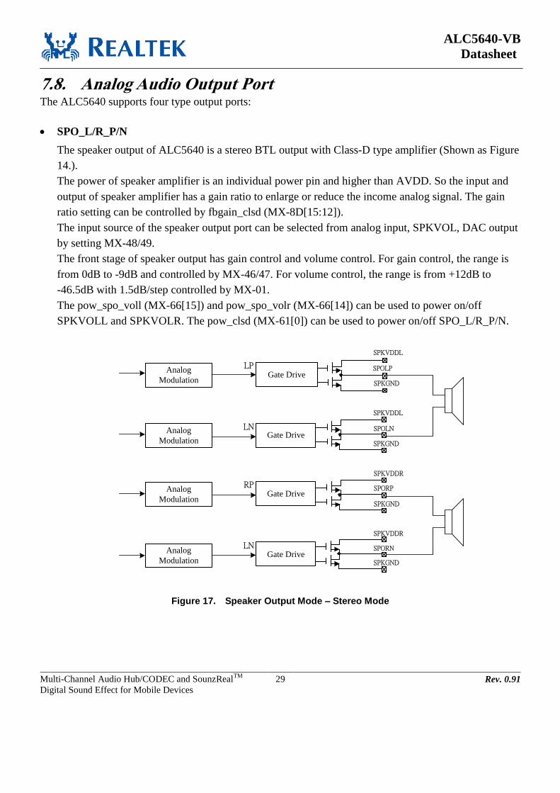
ALC5640-VB
Datasheet
Multi-Channel Audio Hub/CODEC and SounzRealTM
Digital Sound Effect for Mobile Devices
29 Rev. 0.91
7.8. Analog Audio Output Port The ALC5640 supports four type output ports:
SPO_L/R_P/N
The speaker output of ALC5640 is a stereo BTL output with Class-D type amplifier (Shown as Figure
14.).
The power of speaker amplifier is an individual power pin and higher than AVDD. So the input and
output of speaker amplifier has a gain ratio to enlarge or reduce the income analog signal. The gain
ratio setting can be controlled by fbgain_clsd (MX-8D[15:12]).
The input source of the speaker output port can be selected from analog input, SPKVOL, DAC output
by setting MX-48/49.
The front stage of speaker output has gain control and volume control. For gain control, the range is
from 0dB to -9dB and controlled by MX-46/47. For volume control, the range is from +12dB to
-46.5dB with 1.5dB/step controlled by MX-01.
The pow_spo_voll (MX-66[15]) and pow_spo_volr (MX-66[14]) can be used to power on/off
SPKVOLL and SPKVOLR. The pow_clsd (MX-61[0]) can be used to power on/off SPO_L/R_P/N.
SPKVDDL
SPKGND
SPOLP
SPKVDDL
SPKGND
SPOLN
SPKVDDR
SPKGND
SPORP
SPKVDDR
SPKGND
SPORN
Gate Drive
Gate Drive
Gate Drive
Gate Drive
LP
LN
RP
LN
Analog
Modulation
Analog
Modulation
Analog
Modulation
Analog
Modulation
Figure 17. Speaker Output Mode – Stereo Mode

ALC5640-VB
Datasheet
Multi-Channel Audio Hub/CODEC and SounzRealTM
Digital Sound Effect for Mobile Devices
30 Rev. 0.91
HPO_L/R
The headphone output of ALC5640 is a stereo output with cap-free type headphone amplifier. It does
not need to connect external capacitor and can connect to earphone device directly. The headphone
output source can mix from output mixer (OUTMIX) or DAC by setting MX-45. The front stage of
headphone output has volume control and gain control. The volume range is from +12dB to -46.5dB
with 1.5dB/step by MX-02.
En_l_hp and en_r_hp (MX-63[7/6]) can be used to power on/off Headphone Amplifier, and
pow_hpo_voll and pow_hpo_volr (MX-66[11/10]) can be used to power on/off headphone volume
control. In addition, pow_pump_hp (MX-8E[3]) can be used to power on/off charge pump circuit for
Headphone Amplifier.
MONO_P/N
The mono output is a differential output with Class-AB type amplifier. The mono output source can
be mixed from analog input, OUTVOL and DAC output by setting MX-4C[15:11]. The front stage of
mono output has gain control for attenuation, the gain control is 0dB or -6dB by MX-4C[10].
Line_OUT_L/R
The output type is line type output. The output is a stereo single ended output. The input can be
selected from OUTVOL or DAC output by setting MX-53[15:12]. The front stage of LOUT output
has gain control for attenuation. The gain control is 0dB or -6dB by MX-53[11].
ALC5640-VB
Datasheet
Multi-Channel Audio Hub/CODEC and SounzRealTM
Digital Sound Effect for Mobile Devices
31 Rev. 0.91
7.9. Multi-Function Pins There are five multi-function pins in ALC5640. For different functions in each pins are controlled by
register. You need to set the right register settings for each multi-function pins by your application.
GPIO1/IRQ – Pin 40
The pin default is GPIO function. If want to change to IRQ output, write MX-C0[15] to 1’b that will
switch to IRQ function.
GPIO2/DMIC_SCL – Pin 41
The pin default is GPIO function. If want to change to DMIC clock output, write MX-C0[14] to 1’b that
will switch to DMIC clock output function.
IN1P/DMIC1_DAT – Pin 5
The pin default is DMIC1 data input function. In DMIC1 data input function, need to set these register
settings:
1. Power down IN1P – MX-64[15] = 0’b
2. Mute IN1 to each analog mixer -
(RECMIXL/RECMIXR/OUTMIXL/OUTMIXR/SPOLMIX/SPORMIX/MONOMIX).
3. Set IN1 as single-end mode – MX-FA[9] = 1’b
In IN1P microphone input function, need to power down DMIC interface – MX75[15] = 0’b.
IN1N/DMIC2_DAT/JD1 – Pin 6
The pin default is DMIC1 data input function. In DMIC2 data input function, need to set these register
settings:
1. Power down IN1N – MX-64[15] = 0’b
2. Mute IN1 to each analog mixer -
(RECMIXL/RECMIXR/OUTMIXL/OUTMIXR/SPOLMIX/SPORMIX/MONOMIX).
3. Set IN1 as single-end mode – MX-FA[9] = 1’b
In IN1N microphone input function, need to power down DMIC interface – MX75[15] = 0’b.
In JD1 jack detection function, need to set these register settings:
1. Power down IN1N – MX-64[15] = 0’b
2. Mute IN1 to each analog mixer -
(RECMIXL/RECMIXR/OUTMIXL/OUTMIXR/SPOLMIX/SPORMIX/MONOMIX).
3. Set IN1 as single-end mode – MX-FA[9] = 1’b
4. Enable JD1 as jack detection source – MX-BB[15:13] = 010’b

ALC5640-VB
Datasheet
Multi-Channel Audio Hub/CODEC and SounzRealTM
Digital Sound Effect for Mobile Devices
32 Rev. 0.91
IN2N/JD2 – Pin 8
In IN2N microphone input function, need to disable JD2 jack detection function – MX-BB[15:13] =
000’b and MX-FB[8] = 0’b.
In JD2 jack detection function, need to set these register settings:
1. Power down IN2N – MX-64[12] = 0’b
2. Mute IN2 to each analog mixer - (RECMIXL/RECMIXR/OUTMIXR).
3. Set IN2 as single-end mode – MX-FA[8] = 1’b
4. Enable JD2 as jack detection source – MX-BB[15:13] = 011’b
Enable JD2 as extra jack detection source – MX-FB[8] = 1’b

ALC5640-VB
Datasheet
Multi-Channel Audio Hub/CODEC and SounzRealTM
Digital Sound Effect for Mobile Devices
33 Rev. 0.91
7.10. DRC and AGC Function The Dynamic Range Controller (DRC) dynamically adjusts the input signal and let the output signal
achieve the target level. The ALC5640 supports playback DRC for DAC path, and the DRC can also be
used as AGC(Auto Gain Controller) for ADC path. The control register is at MX-B4[15:14]. The function
block is shown as below. The signal input pass through the Pre-Gain first, then DRC volume and
Post-Gain then output. The Pre-Gain is use to enlarge the input signal. The DRC volume is use to
attenuate the signal after detected by DRC. The Post-Gain is use to fine tune the signal after pass DRC
tuning.
I2C Interface Pre-GainDRC
VolumePost-Gain DAC
DRC
-95.625 ~ 0dB
0.375/step
-11.625 ~ 12dB, 0.375/step
MXB5[13:8]
0 ~ 28.5dB, 1.5/step
MXB5[4:0]
1. Limiter level
2. Attack / Release time
3. Zero data
Figure 18. DAC DRC Function Block
Analog
Pre-BoostPre-Gain
AGC
VolumeI2S Interface
AGC
-95.625 ~ 0dB
0.375/step
1. Limiter level
2. Attack / Release time
3. Noise gate
ADC
0 ~ 28.5dB, 1.5/step
MXB5[4:0]
Post-Gain
-11.625 ~ 12dB, 0.375/step
MXB5[13:8]
Figure 19. ADC AGC Function Block

ALC5640-VB
Datasheet
Multi-Channel Audio Hub/CODEC and SounzRealTM
Digital Sound Effect for Mobile Devices
34 Rev. 0.91
Playback/Recording Mode:
For DAC playback or ADC recording mode, when the input signal exceeds target threshold, the signal
will decrease “DRC/AGC Digital Volume” (0.375dB/step at every zero-crossing) until drop to target
level then keep the digital volume. When input signal is below the target threshold, the signal will step-up
“DRC/AGC Digital Volume” (0.375dB/step every zero-crossing) until return to original level. If want to
return to the target level, need to set the pre-gain to achieve.
Fine tune parameters:
Limiter Threshold: 0 ~ -46.5dB, 1.5dB/step, MX-B6[11:7]
Attack Rate: T=(4*2^n)/sample rate, n = MX-B4[12:8]
Recovery Rate: T=(4*2^n)/sample rate, n = MX-B4[4:0]
Volume
0dB
Input signal
Output signal
Target Level
Attack RateRecovery Rate
Figure 20. DRC/AGC for Playback/Recording Mode
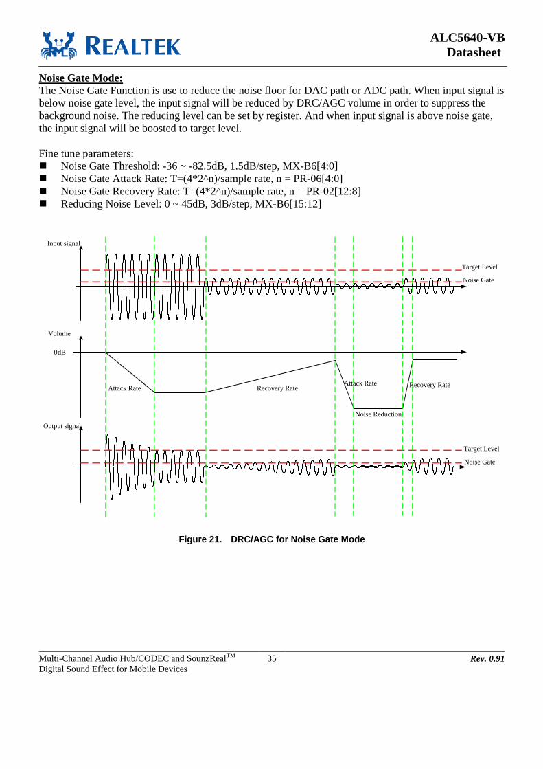
ALC5640-VB
Datasheet
Multi-Channel Audio Hub/CODEC and SounzRealTM
Digital Sound Effect for Mobile Devices
35 Rev. 0.91
Noise Gate Mode:
The Noise Gate Function is use to reduce the noise floor for DAC path or ADC path. When input signal is
below noise gate level, the input signal will be reduced by DRC/AGC volume in order to suppress the
background noise. The reducing level can be set by register. And when input signal is above noise gate,
the input signal will be boosted to target level.
Fine tune parameters:
Noise Gate Threshold: -36 ~ -82.5dB, 1.5dB/step, MX-B6[4:0]
Noise Gate Attack Rate: T=(4*2^n)/sample rate, n = PR-06[4:0]
Noise Gate Recovery Rate: T=(4*2^n)/sample rate, n = PR-02[12:8]
Reducing Noise Level: 0 ~ 45dB, 3dB/step, MX-B6[15:12]
Volume
0dB
Input signal
Output signal
Target Level
Attack Rate Recovery Rate
Noise Gate
Attack Rate Recovery Rate
Noise Gate
Target Level
Noise Reduction
Figure 21. DRC/AGC for Noise Gate Mode
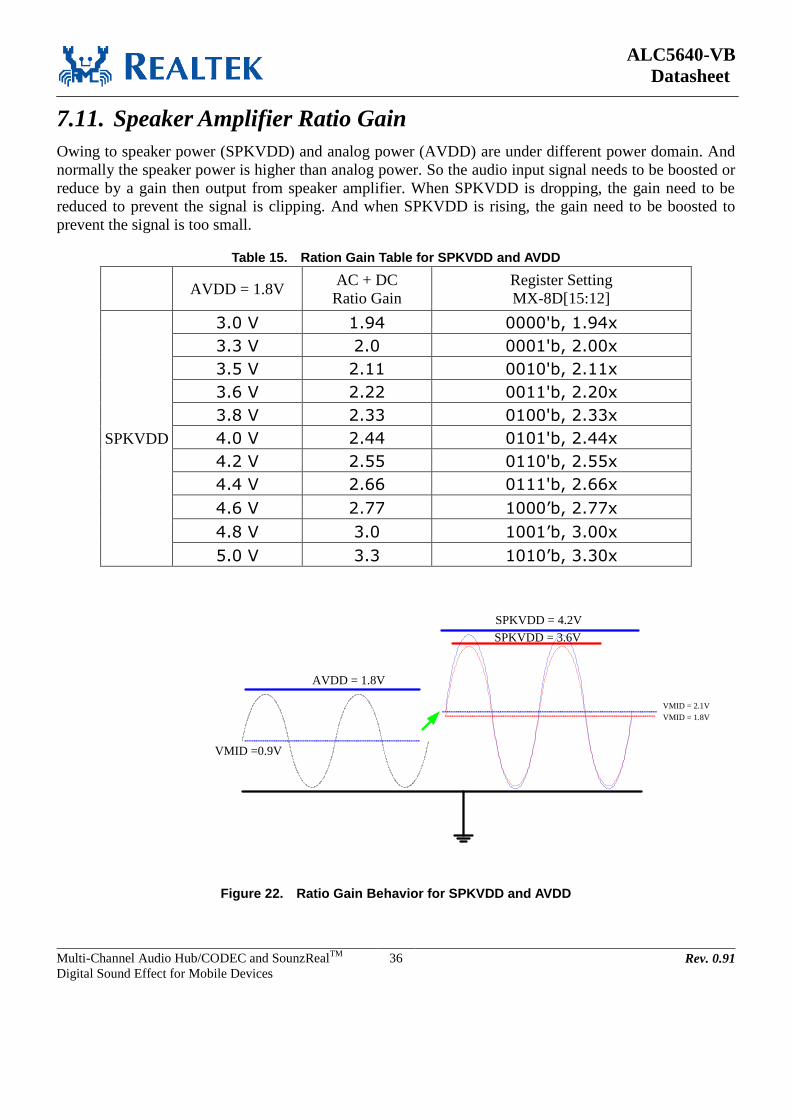
ALC5640-VB
Datasheet
Multi-Channel Audio Hub/CODEC and SounzRealTM
Digital Sound Effect for Mobile Devices
36 Rev. 0.91
7.11. Speaker Amplifier Ratio Gain
Owing to speaker power (SPKVDD) and analog power (AVDD) are under different power domain. And
normally the speaker power is higher than analog power. So the audio input signal needs to be boosted or
reduce by a gain then output from speaker amplifier. When SPKVDD is dropping, the gain need to be
reduced to prevent the signal is clipping. And when SPKVDD is rising, the gain need to be boosted to
prevent the signal is too small.
Table 15. Ration Gain Table for SPKVDD and AVDD
AVDD = 1.8V AC + DC
Ratio Gain
Register Setting
MX-8D[15:12]
SPKVDD
3.0 V 1.94 0000'b, 1.94x
3.3 V 2.0 0001'b, 2.00x
3.5 V 2.11 0010'b, 2.11x
3.6 V 2.22 0011'b, 2.20x
3.8 V 2.33 0100'b, 2.33x
4.0 V 2.44 0101'b, 2.44x
4.2 V 2.55 0110'b, 2.55x
4.4 V 2.66 0111'b, 2.66x
4.6 V 2.77 1000’b, 2.77x
4.8 V 3.0 1001’b, 3.00x
5.0 V 3.3 1010’b, 3.30x
AVDD = 1.8V
SPKVDD = 4.2V
VMID =0.9V
VMID = 2.1V
SPKVDD = 3.6V
VMID = 1.8V
Figure 22. Ratio Gain Behavior for SPKVDD and AVDD

ALC5640-VB
Datasheet
Multi-Channel Audio Hub/CODEC and SounzRealTM
Digital Sound Effect for Mobile Devices
37 Rev. 0.91
7.12. SounzReal Sound Effect
The Realtek’s SounzReal sound effect is composed of:
OmniHeadphone
OmniSound
Dipole Speaker
MP3 Enhancement
BassBack
BassBoost
7.13. Equalizer Block The equalizer block cascades 7 bands of equalizer to tailor the frequency characteristics of embedded
speaker system according to user preferences and to emulate environment sound. The 7 bands equalizer
includes two high pass filter, four band pass filter and one low pass filter. One high pass filter cascaded in
the front end is used to drop low frequency tone, The tone has a large amplitude and may damage a mini
speaker. The high pass filter can be used to adjust Treble strength with gain control. One low pass filter
with gain control can adjust the Bass strength. Four bands of bi-quad band pass filters are used to emulate
environment sounds, e.g., ‘Pub’, ‘Live’, ‘Rock’,… etc.. The gain, center frequency and bandwidth of each
filter are all programmable.
7.14. Wind Filter with Dynamic Wind Noise Detector
7.14.1. Wind Filter
The wind filter is implemented by a high pass filter. The wind filter is mainly for ADC recording used.
The cut-off frequency of wind filter is programmable and is varied according to different sample rate. The
filter is used to remove DC offset at normal condition, and to remove wind noise at application mode.
Wind filter setting procedure:
Step1: Disable wind noise detection if needed – PR-6C[15]
Step2: Disable wind filter – MX-D3[15]
Step3: Select target sample rate – MX-D3[14:12] and MX-D3[10:8]
Step3: Fine tune wind filter Fc – PR-6E[11:6]
Step4: Enable wind filter – MX-D3[15]
Step5: Enable wind noise detection if needed – MX-D3[15]

ALC5640-VB
Datasheet
Multi-Channel Audio Hub/CODEC and SounzRealTM
Digital Sound Effect for Mobile Devices
38 Rev. 0.91
The following table (Table 13.) is shown the Fc with sample rate selection.
For the formula of Fc calculation is also shown as:
Fc = (Fs * tan-1
(a/(2-a))) / π
Where:
Sample rate = 8K/12K/16K (MX-D3[14:12] and [10:8]), a = 2-6
+ n * 2-6
(n is PR-6E[11:6])
Sample rate = 24K/32K (MX-D3[14:12] and [10:8]), a = 2-7
+ n * 2-7
(n is PR-6E[11:6])
Sample rate = 44.1K/48L (MX-D3[14:12] and [10:8]), a = 2-8
+ n * 2-8
(n is PR-6E[11:6])
Sample rate = 88.2K/96L (MX-D3[14:12] and [10:8]), a = 2-9
+ n * 2-9
(n is PR-6E[11:6])
Sample rate = 176.4K/192L (MX-D3[14:12] and [10:8]), a = 2-10
+ n * 2-10
(n is PR-6E[11:6])
Table 16. Sample Rate with filter coefficient for Wind Filter
PR-6E[11:6]
n
L & R Channel Sample Rate Setting
8K 16K 32K 44.1K 48K
000000’b, 0 20.0 40.1 39.9 27.4 29.8
000001’b, 1 40.4 80.8 80.2 55.0 59.9
000010’b, 2 61.1 122.2 120.7 82.7 90.0
000011’b, 3 82.1 164.2 161.6 110.5 120.3
000100’b, 4 103.4 206.9 202.8 138.4 150.6
000101’b, 5 125.1 250.2 244.4 166.4 181.1
000110’b, 6 147.1 294.3 286.2 194.5 211.7
000111’b, 7 169.5 339.0 328.4 222.7 242.5
001000’b, 8 192.2 384.4 371.0 251.1 273.3
001001’b, 9 215.2 430.5 413.8 279.5 304.3
001010’b, 10 238.7 477.4 457.0 308.1 335.4
001011’b, 11 262.4 524.9 500.5 336.8 366.6
001100’b, 12 286.6 573.2 544.4 365.6 397.9
001101’b, 13 311.1 622.3 588.6 394.5 429.4
001110’b, 14 336.0 672.1 633.2 423.5 460.9
001111’b, 15 361.3 722.6 678.1 452.6 492.6
010000’b, 16 386.9 773.9 723.3 481.9 524.5
010001’b, 17 413.0 826.0 768.9 511.2 556.4
010010’b, 18 439.4 878.9 814.9 540.7 588.5
010011’b, 19 466.2 932.5 861.2 570.3 620.7
010100’b, 20 493.5 987.0 907.8 600.0 653.0
010101’b, 21 521.1 1042.2 954.9 629.8 685.5
010110’b, 22 549.1 1098.2 1002.2 659.7 718.1
010111’b, 23 577.5 1155.0 1050.0 689.8 750.8
011000’b, 24 606.3 1212.7 1098.1 719.9 783.6
011001’b, 25 635.5 1271.1 1146.6 750.2 816.6
011010’b, 26 665.1 1330.3 1195.5 780.6 849.6
011011’b, 27 695.2 1390.4 1244.7 811.1 882.9
011100’b, 28 725.6 1451.2 1294.3 841.8 916.2
011101’b, 29 756.4 1512.9 1344.3 872.5 949.7
011110’b, 30 787.6 1575.3 1394.7 903.4 983.3
011111’b, 31 819.3 1638.6 1445.4 934.4 1017.0
100000’b, 32 851.3 1702.7 1496.5 965.5 1050.9
100001’b, 33 883.7 1767.5 1548.0 996.8 1084.9
100010’b, 34 916.6 1822.3 1599.9 1028.1 1119.0

ALC5640-VB
Datasheet
Multi-Channel Audio Hub/CODEC and SounzRealTM
Digital Sound Effect for Mobile Devices
39 Rev. 0.91
PR-6E[11:6]
n
L & R Channel Sample Rate Setting
8K 16K 32K 44.1K 48K
100011’b, 35 949.8 1899.6 1652.2 1059.6 1153.3
100100’b, 36 983.3 1966.7 1704.9 1091.2 1187.7
100101’b, 37 1017.3 2034.7 1757.9 1122.9 1222.2
100110’b, 38 1051.6 2103.3 1811.4 1154.8 1256.9
100111’b, 39 1086.3 2172.7 1865.2 1186.7 1291.7
101000’b, 40 1121.4 2242.9 1919.5 1218.8 1326.6
101001’b, 41 1156.8 2313.7 1974.1 1251.0 1361.7
101010’b, 42 1192.6 2385.2 2029.1 1283.4 1396.9
101011’b, 43 1228.7 2457.4 2084.6 1315.8 1432.2
101100’b, 44 1265.1 2530.2 2140.4 1348.4 1467.7
101101’b, 45 1301.8 2603.6 2196.6 1381.1 1503.3
101110’b, 46 1338.8 2677.7 2253.3 1414.0 1539.0
101111’b, 47 1376.1 2752.3 2310.3 1447.0 1574.9
110000’b, 48 1413.7 2827.5 2367.7 1480.0 1610.9
110001’b, 49 1451.5 2903.1 2425.5 1513.3 1647.1
110010’b, 50 1489.6 2979.3 2483.8 1546.6 1683.4
110011’b, 51 1528.0 3056.0 2542.4 1580.1 1719.8
110100’b, 52 1566.5 3133.1 2601.5 1613.7 1756.4
110101’b, 53 1605.3 3210.6 2660.9 1647.4 1793.1
110110’b, 54 1644.2 3288.4 2720.8 1681.3 1830.0
110111’b, 55 1683.3 3366.6 2781.0 1715.3 1867.0
111000’b, 56 1722.5 3445.1 2841.7 1749.4 1904.1
111001’b, 57 1761.9 3523.9 2902.7 1783.6 1941.4
111010’b, 58 1801.4 3602.9 2964.2 1818.0 1978.8
111011’b, 59 1841.0 3682.1 3026.1 1852.5 2016.3
111100’b, 60 1880.7 3761.4 3088.3 1887.1 2054.0
111101’b, 61 1920.4 3840.8 3151.0 1921.9 2091.9
111110’b, 62 1960.2 3920.4 3214.1 1956.8 2129.9
111111’b, 63 2000.0 4000.0 3277.5 1991.8 2168.0

ALC5640-VB
Datasheet
Multi-Channel Audio Hub/CODEC and SounzRealTM
Digital Sound Effect for Mobile Devices
40 Rev. 0.91
7.14.2. Dynamic Wind Noise Detector
The wind filter builds in wind noise detector. It can dynamic detect wind noise strength and auto adjust
FC of wind filter to make sure good recording quality. The wind noise detector needs two microphones for
implementation. The Figure 21 is showing wind noise threshold and FC adjustment for wind noise
detector.
When wind noise is higher than high threshold that mean strong wind been detected and the FC of wind
filter will be auto set to FC3. The wind noise flag been shown at PR-73[13:12].
When wind noise is higher than low threshold and lower than high threshold that mean weak wind been
detected and the FC of wind filter will be auto set to FC2. The wind noise flag been shown at
PR-73[13:12].
When wind noise is lower than low threshold that mean no wind been detected and the FC of wind filter
will be auto set to FC1. The wind noise flag been shown at PR-73[13:12].
NoWind Weak Wind
Wind Noise High Threshold
– PR-70[9:0]
Wind Noise Low Threshold
– PR-6F[9:0]
High Pass Filter FC3
– PR-6E[5:0]
High Pass Filter FC2
– PR-6D[9:4]
High Pass Filter FC1
– PR-6D[15:10]
Wind Noise Flag
- PR-73[13] = 0'b
- PR-73[12] = 0'b
Strong Wind
Wind Noise Flag
- PR-73[13] = 1'b
- PR-73[12] = 0'b
Wind Noise Flag
- PR-73[13] = 1'b
- PR-73[12] = 1'b
Figure 23. Wind Noise Detector

ALC5640-VB
Datasheet
Multi-Channel Audio Hub/CODEC and SounzRealTM
Digital Sound Effect for Mobile Devices
41 Rev. 0.91
7.15. I2C Control Interface
I2C is a 2-wire (SCL/SDA) half-duplex serial communication interface, supporting only slave mode. SCL
is used for clock and SDA is for data. SCL clock supports up to 400KHz rate and SDA data is a open
drain structure. The input has built-in spike filter and can remove less than 50ns spike at SCL and SDA.
7.15.1. Address Setting
Table 17. Address Setting (0x38h)
(MSB) BIT (LSB)
0 0 1 1 1 0 0 R/W
7.15.2. Complete Data Transfer
Data Transfer over I2C Control Interface
Figure 24. Data Transfer Over I2C Control Interface
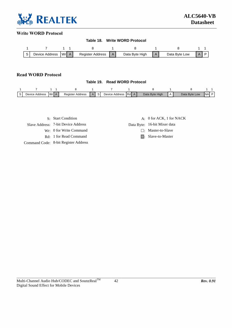
ALC5640-VB
Datasheet
Multi-Channel Audio Hub/CODEC and SounzRealTM
Digital Sound Effect for Mobile Devices
42 Rev. 0.91
Write WORD Protocol
Table 18. Write WORD Protocol
S Device Address Wr Register Address Data Byte High Data Byte Low PA A A A
1 7 1 1 8 1 8 1 8 1 1
Read WORD Protocol
Table 19. Read WORD Protocol
S Device Address Wr Data Byte High Data Byte Low PS Device AddressA A Rd NAA
1 7 1 1 8 1 7 1 8 1 18 1
Register Address A
S: Start Condition A: 0 for ACK, 1 for NACK
Slave Address: 7-bit Device Address Data Byte: 16-bit Mixer data
Wr: 0 for Write Command : Master-to-Slave
Rd: 1 for Read Command : Slave-to-Master
Command Code: 8-bit Register Address
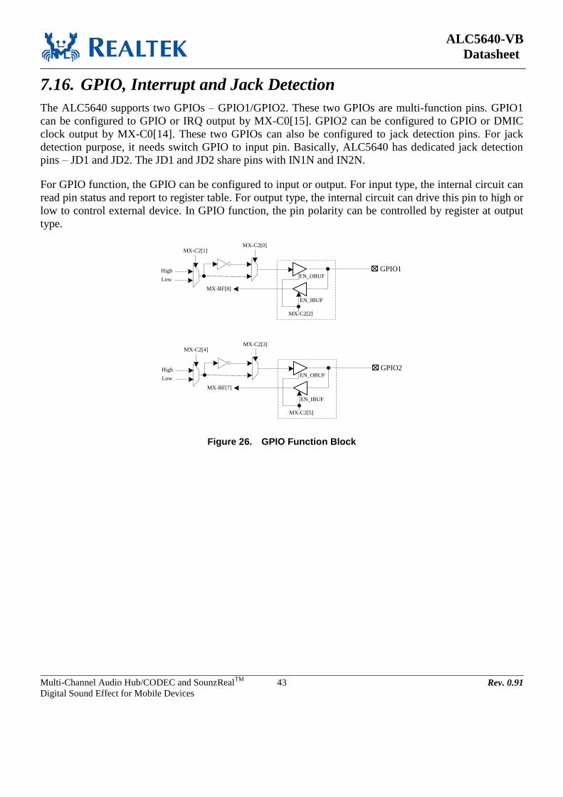
ALC5640-VB
Datasheet
Multi-Channel Audio Hub/CODEC and SounzRealTM
Digital Sound Effect for Mobile Devices
43 Rev. 0.91
7.16. GPIO, Interrupt and Jack Detection
The ALC5640 supports two GPIOs – GPIO1/GPIO2. These two GPIOs are multi-function pins. GPIO1
can be configured to GPIO or IRQ output by MX-C0[15]. GPIO2 can be configured to GPIO or DMIC
clock output by MX-C0[14]. These two GPIOs can also be configured to jack detection pins. For jack
detection purpose, it needs switch GPIO to input pin. Basically, ALC5640 has dedicated jack detection
pins – JD1 and JD2. The JD1 and JD2 share pins with IN1N and IN2N.
For GPIO function, the GPIO can be configured to input or output. For input type, the internal circuit can
read pin status and report to register table. For output type, the internal circuit can drive this pin to high or
low to control external device. In GPIO function, the pin polarity can be controlled by register at output
type.
GPIO1
MX-C2[1]
EN_OBUF
EN_IBUF
MX-C2[2]
High
Low
MX-C2[0]
MX-BF[8]
GPIO2
MX-C2[4]
EN_OBUF
EN_IBUF
MX-C2[5]
High
Low
MX-C2[3]
MX-BF[7]
Figure 26. GPIO Function Block

ALC5640-VB
Datasheet
Multi-Channel Audio Hub/CODEC and SounzRealTM
Digital Sound Effect for Mobile Devices
44 Rev. 0.91
For IRQ function as shown Figure 24, the IRQ output source can be selected from JD Status, JD2 Status,
Over-Temperature Status and MICBIAS1 Over-Current Status. When either status is trigged, the GPIO
will output a flag as interrupt signal.
sta_jd_internal(MX-BF[4])
IRQ
MX-BD[11]
MX-BD[15]
ovt_status(MX-BF[3])
MX-BD[10]MX-BD[14]
ovc_micbias1(MX-BE[3])
MX-BE[7]
MX-BE[15]Sticky Control
MX-BD[13]
Sticky Control
MX-BD[12]
Sticky Control
MX-BE[11]
Sta_jd2_internal(MX-FB[11])
MX-FB[10]
Sticky Control
MX-FB[9]
MX-FB[11]
Figure 27. IRQ Function Block
In general, the IRQ output needs to combine with JD function. When JD is trigger, IRQ will output a flag
to host to notice S/W driver. The S/W driver will do something by system design. The behavior flow
chard as following:
Device Plug-In
JD Triggered
Initial Settings
(For JD and IRQ)
IRQ Flag Output to Host
S/W Driver Settings
Clear JD Status for Next
JD Trigger

ALC5640-VB
Datasheet
Multi-Channel Audio Hub/CODEC and SounzRealTM
Digital Sound Effect for Mobile Devices
45 Rev. 0.91
The MICBIAS supports short detection function. When MICBIAS circuit is short, MICBIAS circuit will
generate an over-current flag. The flag can generate an interrupt signal to notice host and let S/W do
follow-up processes.
For jack detection function as shown Figure 25. There are two internal JD status can be set. For
sta_jd_internal – MX-BF[4], there are four pins can as jack detection source - GPIO1, GPIO2, JD1 (share
with IN1N) and JD2 (share with IN2N). The source selection control is at MX-BB[15:13]. For another JD
status – sta_jd2_internal – MX-FB[11] is dedicated for JD2 pin. And the enable control is by MX-FB[8].
Owing to JD2 can as sta_jd_internal status and also can as sta_jd2_internal status, JD2 can’t be used
together for these two status.
JD S
ou
rce
MX-BB[15:13]
MX-BF[4]Sta_jd_internal
JD1
JD2
GPIO1
GPIO2
EN_JD2
MX-FB[8]
MX-FB[11]Sta_jd2_internal
Figure 27. JD Source Selection
The jack detect function can be used to turn-on or turn-off the related output ports. When jack detect pin
is trigged, the selected output ports will be turn-on or turn-off. For example on HP and SPK auto switch
when JD is trigger.
Setting procedure:
1. Select JD source: use JD1 as JD source. MX-BB[15:13] = 010’b
2. Set wanted behavior by JD action – HP & SPK auto switch when JD is trigger.
MX-BB[11:6] = 111010’b
3. When JD status is low, HP_OUT is mute and SPK is un-mute.
When JD status is low go high, HP is un-mute and SPK is mute.
Note: For HP and SPK jack switch function, driver need to turn-on DAC to HP path and DAC to SPK
path first. The register control of MX-BB[11:6] is only do mute/un-mute function for HP and SPK.
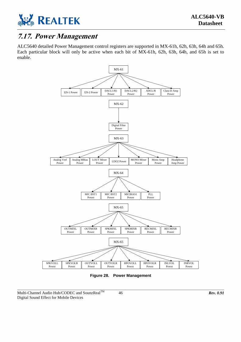
ALC5640-VB
Datasheet
Multi-Channel Audio Hub/CODEC and SounzRealTM
Digital Sound Effect for Mobile Devices
46 Rev. 0.91
7.17. Power Management
ALC5640 detailed Power Management control registers are supported in MX-61h, 62h, 63h, 64h and 65h.
Each particular block will only be active when each bit of MX-61h, 62h, 63h, 64h, and 65h is set to
enable.
MX-61
I2S-1 Power I2S-2 PowerDACL1/R1
Power
DACL2/R2
Power
ADCL/R
Power
Class-D Amp
Power
MX-62
Digital Filter
Power
MX-63
Analog Vref
Power
Analog MBias
Power
LOUT Mixer
Power
MONO Mixer
Power
Mono Amp
Power
Headphone
Amp PowerLDO2 Power
MX-64
MIC BST1
Power
MIC BST2
Power
MICBIAS1
Power
PLL
Power
MX-65
OUTMIXL
Power
OUTMIXR
Power
SPKMIXL
Power
SPKMIXR
Power
RECMIXL
Power
RECMIXR
Power
MX-65
SPKVOLR
Power
OUTVOLL
Power
OUTVOLR
Power
HPOVOLL
Power
HPOVOLR
Power
INLVOL
Power
INRVOL
Power
SPKVOLL
Power
Figure 28. Power Management
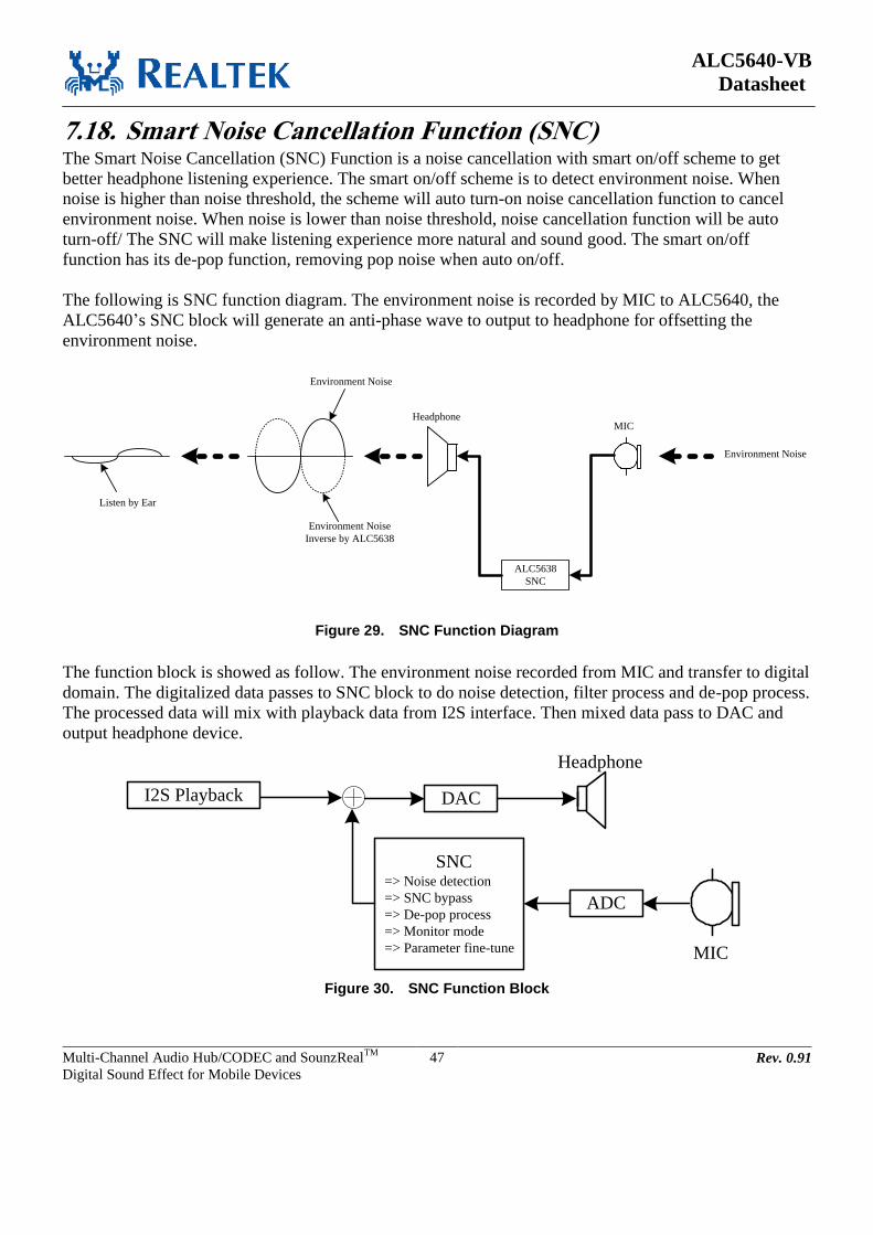
ALC5640-VB
Datasheet
Multi-Channel Audio Hub/CODEC and SounzRealTM
Digital Sound Effect for Mobile Devices
47 Rev. 0.91
7.18. Smart Noise Cancellation Function (SNC) The Smart Noise Cancellation (SNC) Function is a noise cancellation with smart on/off scheme to get
better headphone listening experience. The smart on/off scheme is to detect environment noise. When
noise is higher than noise threshold, the scheme will auto turn-on noise cancellation function to cancel
environment noise. When noise is lower than noise threshold, noise cancellation function will be auto
turn-off/ The SNC will make listening experience more natural and sound good. The smart on/off
function has its de-pop function, removing pop noise when auto on/off.
The following is SNC function diagram. The environment noise is recorded by MIC to ALC5640, the
ALC5640’s SNC block will generate an anti-phase wave to output to headphone for offsetting the
environment noise.
MICHeadphone
ALC5638
SNC
Environment Noise
Environment Noise
Inverse by ALC5638
Listen by Ear
Environment Noise
Figure 29. SNC Function Diagram
The function block is showed as follow. The environment noise recorded from MIC and transfer to digital
domain. The digitalized data passes to SNC block to do noise detection, filter process and de-pop process.
The processed data will mix with playback data from I2S interface. Then mixed data pass to DAC and
output headphone device.
DAC
ADC
SNC=> Noise detection
=> SNC bypass
=> De-pop process
=> Monitor mode
=> Parameter fine-tune MIC
Headphone
I2S Playback
Figure 30. SNC Function Block

ALC5640-VB
Datasheet
Multi-Channel Audio Hub/CODEC and SounzRealTM
Digital Sound Effect for Mobile Devices
48 Rev. 0.91
7.19. Programmable Register Array The Programmable Register Array is used for continuing executing register set by one register command.
These registers are need to program first. There are 16-sequences register settings can be set. For each
sequence, can fill in MX type registers, PR type register or time delay (100us ~ 100ms). These
16-sequences registers can be divided to two sequencers. The start point and end point for each sequencer
can be set from sequence-0 to sequence-15. For example, you can program sequencer-1 to execute
sequence-0 to sequence-10 and sequencer-2 to execute sequence-11 to sequence-15 or program
sequencer-1 to execute sequence -6 to sequence -15 and sequencer-2 to execute sequence -0 to sequence
-5.
The Table 17 shown as programmable register table with two sequencers.
Table 20. Programmable Register Table
Sequencer
(1-bit)
Sequences
(4-bit)
Delay Time
(8-bit)
Register Level
(1-bit)
Register Index
(8-bit)
Register Data
(16-bit)
1
Start 0000’b - x xx xxxx
- 0001’b xx - - -
- 0010’b - x xx xxxx
- 0011’b xx - - -
- 0100’b - x xx xxxx
- 0101’b xx - - -
End 0110’b - x xx xxxx
2
Start 0111’b xx - - -
- 1000’b - x xx xxxx
- 1001’b xx - - -
- 1010’b - x xx xxxx
- 1011’b xx - - -
- 1100’b - x xx xxxx
- 1101’b xx - - -
- 1110’b - x xx xxxx
End 1111’b xx - - -
Settings Procedures:
1. Set Programmable Register Table
=> Set register level (MX-C8[9])/register index (MX-C8[7:0])/register data (MX-C9) for each
sequence (MX-C8[15:12])
=> Set delay time (MX-CA[15:8]) for each sequence (MX-C8[15:12])
=> Set start point (MX-CB[11:8]/MX-CC[11:8]) and end point (MX-CB[3:0]/MX-CC[3:0]) for each
sequencer
2. Enable Programmable Register Function (MX-CA[7])
3. Execute Sequencer-1/2
=> Sequencer-1 (MX-CA[6])
=> Sequencer-2 (MX-CA[5])
4. Check Sequencer-1/2 finished or not?
=> Sequencer-1 (MX-C8[11])
=> Sequencer-2 (MX-C8[10])
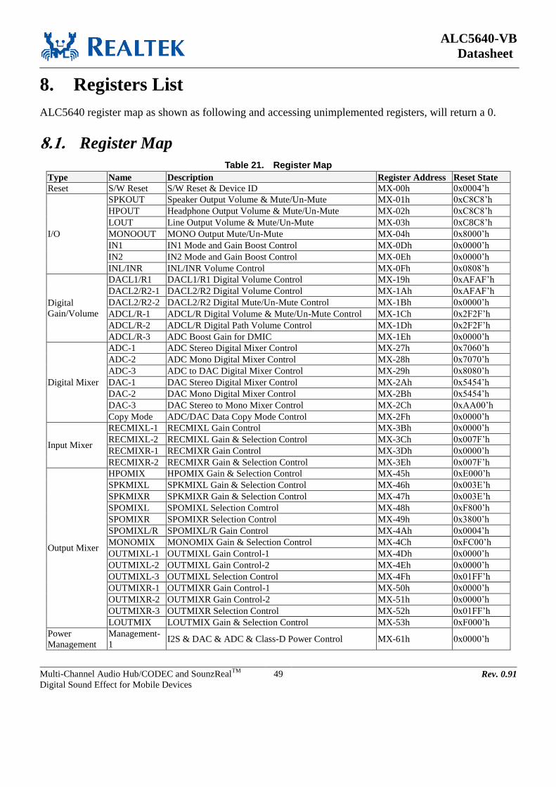
ALC5640-VB
Datasheet
Multi-Channel Audio Hub/CODEC and SounzRealTM
Digital Sound Effect for Mobile Devices
49 Rev. 0.91
8. Registers List
ALC5640 register map as shown as following and accessing unimplemented registers, will return a 0.
8.1. Register Map Table 21. Register Map
Type Name Description Register Address Reset State
Reset S/W Reset S/W Reset & Device ID MX-00h 0x0004’h
I/O
SPKOUT Speaker Output Volume & Mute/Un-Mute MX-01h 0xC8C8’h
HPOUT Headphone Output Volume & Mute/Un-Mute MX-02h 0xC8C8’h
LOUT Line Output Volume & Mute/Un-Mute MX-03h 0xC8C8’h
MONOOUT MONO Output Mute/Un-Mute MX-04h 0x8000’h
IN1 IN1 Mode and Gain Boost Control MX-0Dh 0x0000’h
IN2 IN2 Mode and Gain Boost Control MX-0Eh 0x0000’h
INL/INR INL/INR Volume Control MX-0Fh 0x0808’h
Digital
Gain/Volume
DACL1/R1 DACL1/R1 Digital Volume Control MX-19h 0xAFAF’h
DACL2/R2-1 DACL2/R2 Digital Volume Control MX-1Ah 0xAFAF’h
DACL2/R2-2 DACL2/R2 Digital Mute/Un-Mute Control MX-1Bh 0x0000’h
ADCL/R-1 ADCL/R Digital Volume & Mute/Un-Mute Control MX-1Ch 0x2F2F’h
ADCL/R-2 ADCL/R Digital Path Volume Control MX-1Dh 0x2F2F’h
ADCL/R-3 ADC Boost Gain for DMIC MX-1Eh 0x0000’h
Digital Mixer
ADC-1 ADC Stereo Digital Mixer Control MX-27h 0x7060’h
ADC-2 ADC Mono Digital Mixer Control MX-28h 0x7070’h
ADC-3 ADC to DAC Digital Mixer Control MX-29h 0x8080’h
DAC-1 DAC Stereo Digital Mixer Control MX-2Ah 0x5454’h
DAC-2 DAC Mono Digital Mixer Control MX-2Bh 0x5454’h
DAC-3 DAC Stereo to Mono Mixer Control MX-2Ch 0xAA00’h
Copy Mode ADC/DAC Data Copy Mode Control MX-2Fh 0x0000’h
Input Mixer
RECMIXL-1 RECMIXL Gain Control MX-3Bh 0x0000’h
RECMIXL-2 RECMIXL Gain & Selection Control MX-3Ch 0x007F’h
RECMIXR-1 RECMIXR Gain Control MX-3Dh 0x0000’h
RECMIXR-2 RECMIXR Gain & Selection Control MX-3Eh 0x007F’h
Output Mixer
HPOMIX HPOMIX Gain & Selection Control MX-45h 0xE000’h
SPKMIXL SPKMIXL Gain & Selection Control MX-46h 0x003E’h
SPKMIXR SPKMIXR Gain & Selection Control MX-47h 0x003E’h
SPOMIXL SPOMIXL Selection Comtrol MX-48h 0xF800’h
SPOMIXR SPOMIXR Selection Control MX-49h 0x3800’h
SPOMIXL/R SPOMIXL/R Gain Control MX-4Ah 0x0004’h
MONOMIX MONOMIX Gain & Selection Control MX-4Ch 0xFC00’h
OUTMIXL-1 OUTMIXL Gain Control-1 MX-4Dh 0x0000’h
OUTMIXL-2 OUTMIXL Gain Control-2 MX-4Eh 0x0000’h
OUTMIXL-3 OUTMIXL Selection Control MX-4Fh 0x01FF’h
OUTMIXR-1 OUTMIXR Gain Control-1 MX-50h 0x0000’h
OUTMIXR-2 OUTMIXR Gain Control-2 MX-51h 0x0000’h
OUTMIXR-3 OUTMIXR Selection Control MX-52h 0x01FF’h
LOUTMIX LOUTMIX Gain & Selection Control MX-53h 0xF000’h
Power
Management
Management-
1 I2S & DAC & ADC & Class-D Power Control MX-61h 0x0000’h

ALC5640-VB
Datasheet
Multi-Channel Audio Hub/CODEC and SounzRealTM
Digital Sound Effect for Mobile Devices
50 Rev. 0.91
Type Name Description Register Address Reset State
Management-
2 Digital Filter Power Control MX-62h 0x0000’h
Management-
3
VREF & MBias & LOUTMIX & Mono & HP &
LDO2 Power Control MX-63h 0x00C0’h
Management-
4 MICBST & MICBIAS Power Control MX-64h 0x0000’h
Management-
5 OUTMIX & SPKMIX & RECMIX Power Control MX-65h 0x0000’h
Management-
6
SPOVOL & OUTVOL & HPOVOL & INVOL Power
Control MX-66h 0x0000’h
PR Register PR Index PR Register Index MX-6Ah 0x0000’h
PR Data PR Register Data Mx-6Ch 0x0000’h
Digital
Interface
I2S1 Port Ctrl I2S-1 Interface Control MX-70h 0x8000’h
I2S2 Port Ctrl I2S-2 Interface Control MX-71h 0x8000’h
ADC/DAC
Clock-1 ADC/DAC Clock Control-1 MX-73h 0x1110’h
ADC/DAC
Clock-2 ADC/DAC Clock Control-2 MX-74h 0x0C00’h
Digital MIC DMIC Digital Microphone Control MX-75h 0x1D00’h
Global Clock
Global Clock Global Clock Control MX-80h 0x0000’h
PLL-1 PLL Control-1 MX-81h 0x0000’h
PLL-2 PLL Control-2 MX-82h 0x0000’h
ASRC-1 ASRC Control-1 MX-83h 0x0000’h
ASRC-2 ASRC Control-2 MX-84h 0x0000’h
ASRC-3 ASRC Control-3 MX-85h 0x0008’h
ASRC-6 ASRC Control-4 MX-89h 0x0000’h
ASRC-7 ASRC Control-5 MX-8Ah 0x0000’h
SPK Amp Class-D Class-D OC Control MX-8Ch 0x0228’h
Class-D Class-D Ratio Gain & Mode Control MX-8Dh 0xA800’h
HP Amp HP
HP Output De-Pop Control 1 MX-8Eh 0x0004’h
HP Output De-Pop Control 2 MX-8Fh 0x1100’h
HP Control MX-D6h 0x0400’h
SPK Amp PV Detection SPKVDD Detection Control MX-92h 0x0000’h
MICBIAS MICBIAS MICBIAS Control MX-93h 0x3000’h
EQ
EQ-1 EQ Control-1 MX-B0h 0x2000’h
EQ-2 EQ Control-2 MX-B1h 0x0000’h
EQ-Parameter EQ Low Pass Filter – a1 PR-A0h 0x1C10’h
EQ-Parameter EQ Low Pass Filter – H0 PR-A1h 0x01F4’h
EQ-Parameter EQ Band Pass Filter 1 – a1 PR-A2h 0xC5E9’h
EQ-Parameter EQ Band Pass Filter 1 – a2 PR-A3h 0x1A98’h
EQ-Parameter EQ Band Pass Filter 1 – H0 PR-A4h 0x1D2C’h
EQ-Parameter EQ Band Pass Filter 2 – a1 PR-A5h 0xC882’h
EQ-Parameter EQ Band Pass Filter 2 – a2 PR-A6h 0x1C10’h
EQ-Parameter EQ Band Pass Filter 2 – H0 PR-A7h 0x01F4’h
EQ-Parameter EQ Band Pass Filter 3 – a1 PR-A8h 0xE904’h
EQ-Parameter EQ Band Pass Filter 3 – a2 PR-A9h 0x1C10’h
EQ-Parameter EQ Band Pass Filter 3 – H0 PR-AAh 0x01F4’h
EQ-Parameter EQ Band Pass Filter 4 – a1 PR-ABh 0xE904’h
EQ-Parameter EQ Band Pass Filter 4 – a2 PR-ACh 0x1C10’h
EQ-Parameter EQ Band Pass Filter 4 – H0 PR-ADh 0x01F4’h
EQ-Parameter EQ High Pass Filter 1 – a1 PR-AEh 0x1C10’h
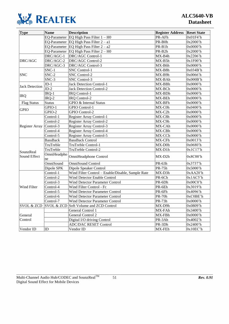
ALC5640-VB
Datasheet
Multi-Channel Audio Hub/CODEC and SounzRealTM
Digital Sound Effect for Mobile Devices
51 Rev. 0.91
Type Name Description Register Address Reset State
EQ-Parameter EQ High Pass Filter 1 – H0 PR-AFh 0x01F4’h
EQ-Parameter EQ High Pass Filter 2 – a1 PR-B0h 0x2000’h
EQ-Parameter EQ High Pass Filter 2 – a2 PR-B1h 0x0000’h
EQ-Parameter EQ High Pass Filter 2 – H0 PR-B2h 0x2000’h
DRC/AGC
DRC/AGC-1 DRC/AGC Control-1 MX-B4h 0x2206’h
DRC/AGC-2 DRC/AGC Control-2 MX-B5h 0x1F00’h
DRC/AGC-3 DRC/AGC Control-3 MX-B6h 0x0000’h
SNC
SNC-1 SNC Control-1 MX-B8h 0x034B’h
SNC-2 SNC Control-2 MX-B9h 0x0066’h
SNC-3 SNC Control-3 MX-BAh 0x000B’h
Jack Detection JD-1 Jack Detection Control-1 MX-BBh 0x0000’h
JD-2 Jack Detection Control-2 MX-BCh 0x0000’h
IRQ IRQ-1 IRQ Control-1 MX-BDh 0x0000’h
IRQ-2 IRQ Control-2 MX-BEh 0x0000’h
Flag Status Status GPIO & Internal Status MX-BFh 0x0000’h
GPIO GPIO-1 GPIO Control-1 MX-C0h 0x0400’h
GPIO-2 GPIO Control-2 MX-C2h 0x0000’h
Register Array
Control-1 Register Array Control-1 MX-C8h 0x0000’h
Control-2 Register Array Control-2 MX-C9h 0x0000’h
Control-3 Register Array Control-3 MX-CAh 0x0000’h
Control-4 Register Array Control-4 MX-CBh 0x0000’h
Control-5 Register Array Control-5 MX-CCh 0x0000’h
SounzReal
Sound Effect
BassBack BassBack Control MX-CFh 0x0013’h
TruTreble TruTreble Control-1 MX-D0h 0x0680’h
TruTreble TruTreble Control-2 MX-D1h 0x1C17’h
OmniHeadpho
ne OmniHeadphone Control MX-D2h 0x8C00’h
OmniSound OmniSound Control PR-63h 0x3737’h
Dipole SPK Dipole Speaker Control PR-75h 0x5000’h
Wind Filter
Control-1 Wind Filter Control – Enable/Disable, Sample Rate MX-D3h 0xAA20’h
Control-2 Wind Detector Enable Control PR-6Ch 0x1AC5’h
Control-3 Wind Detector Parameter Control PR-6Dh 0x00C0’h
Control-4 Wind Filter Control - Fc PR-6Eh 0x3019’h
Control-5 Wind Detector Parameter Control PR-6Fh 0x4096’h
Control-6 Wind Detector Parameter Control PR-70h 0xC0BE’h
Control-7 Wind Detector Parameter Control PR-73h 0x0000’h
SVOL & ZCD SVOL & ZCD Soft Volume and ZCD Control MX-D9h 0x0809’h
General
Control
General Control 1 MX-FAh 0x3400’h
General Control 2 MX-FBh 0x0000’h
Digital I/O driving Control PR-3Ah 0x4002’h
ADC/DAC RESET Control PR-3Dh 0x2400’h
Vendor ID ID Vendor ID MX-FEh 0x10EC’h

ALC5640-VB
Datasheet
Multi-Channel Audio Hub/CODEC and SounzRealTM
Digital Sound Effect for Mobile Devices
52 Rev. 0.91
8.2. MX-00h: S/W Reset & Device ID
Default: 0004’h
Table 22. MX-00h: S/W Reset & Device ID
Port Name Bits Read/Write Reset State Description
Reserved 15:3 R 0’h Reserved
Device_id 2:1 R 2’h ALC5640
Reserved 0 R 0’h Reserved
Note: Writes to this register will reset all registers to their default values.
8.3. MX-01h: Speaker Output Control
Default: C8C8’h
Table 23. MX-01h: Speaker Output Control
Port Name Bits Read/Write Reset State Description
mu_spo_l 15 R/W 1’h Mute Control for Left Speaker Output Port (SPOLP/LN)
0’b: Un-Mute
1’b: Mute
Mu_spkvoll_in 14 R/W 1’h Mute Control for Left Speaker Volume Channel (SPKVOLL)
0’b: Un-Mute
1’b: Mute
vol_spol 13:8 R/W 8’h Left Speaker Channel Volume Control (SPKVOLL)
00’h: +12dB
…
08’h: 0dB
…
27’h: -46.5dB, with 1.5dB/step
mu_spo_r 7 R/W 1’h Mute Control for Right Speaker Output Port (SPORP/RN)
0’b: Un-Mute
1’b: Mute
Mu_spkvolr_in 6 R/W 1’h Mute Control for Right Speaker Volume Channel
(SPKVOLR)
0’b: Un-Mute
1’b: Mute
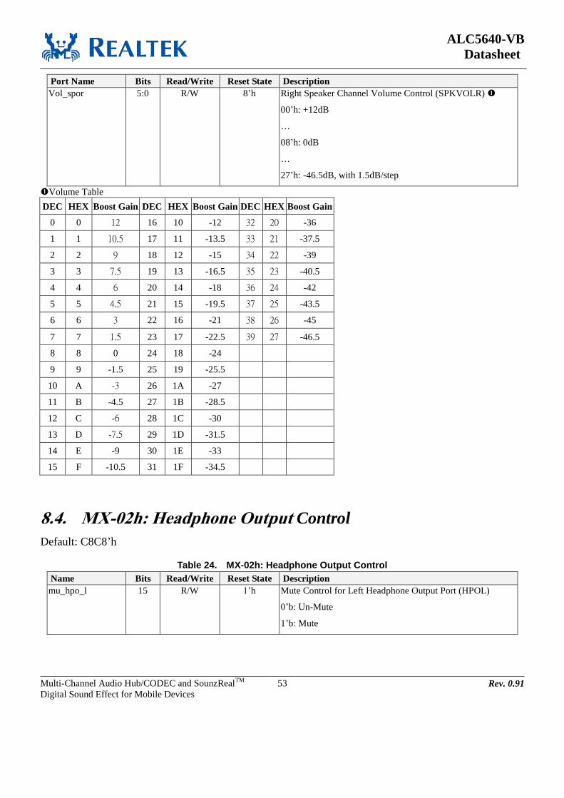
ALC5640-VB
Datasheet
Multi-Channel Audio Hub/CODEC and SounzRealTM
Digital Sound Effect for Mobile Devices
53 Rev. 0.91
Port Name Bits Read/Write Reset State Description
Vol_spor 5:0 R/W 8’h Right Speaker Channel Volume Control (SPKVOLR)
00’h: +12dB
…
08’h: 0dB
…
27’h: -46.5dB, with 1.5dB/step
Volume Table
DEC HEX Boost Gain DEC HEX Boost Gain DEC HEX Boost Gain
0 0 12 16 10 -12 32 20 -36
1 1 10.5 17 11 -13.5 33 21 -37.5
2 2 9 18 12 -15 34 22 -39
3 3 7.5 19 13 -16.5 35 23 -40.5
4 4 6 20 14 -18 36 24 -42
5 5 4.5 21 15 -19.5 37 25 -43.5
6 6 3 22 16 -21 38 26 -45
7 7 1.5 23 17 -22.5 39 27 -46.5
8 8 0 24 18 -24
9 9 -1.5 25 19 -25.5
10 A -3 26 1A -27
11 B -4.5 27 1B -28.5
12 C -6 28 1C -30
13 D -7.5 29 1D -31.5
14 E -9 30 1E -33
15 F -10.5 31 1F -34.5
8.4. MX-02h: Headphone Output Control
Default: C8C8’h
Table 24. MX-02h: Headphone Output Control
Name Bits Read/Write Reset State Description
mu_hpo_l 15 R/W 1’h Mute Control for Left Headphone Output Port (HPOL)
0’b: Un-Mute
1’b: Mute

ALC5640-VB
Datasheet
Multi-Channel Audio Hub/CODEC and SounzRealTM
Digital Sound Effect for Mobile Devices
54 Rev. 0.91
Name Bits Read/Write Reset State Description
Mu_hpovoll_in 14 R/W 1’h Mute Control for Left Headphone Volume Channel
(HPOVOLL)
0’b: Un-Mute
1’b: Mute
vol_hpol 13:8 R/W 8’h Left Headphone Channel Volume Control (HPOVOLL)
00’h: +12dB
…
08’h: 0dB
…
27’h: -46.5dB, with 1.5dB/step
mu_hpo_r 7 R/W 1’h Mute Control Right Headphone Output Port (HPOR)
0’b: Un-Mute
1’b: Mute
Mu_hpovolr_in 6 R/W 1’h Mute Control for Right Headphone Volume Channel
(HPOVOLR)
0’b: Un-Mute
1’b: Mute
Vol_hpor 5:0 R/W 8’h Right Headphone Channel Volume Control (HPOVOLR)
00’h: +12dB
…
08’h: 0dB
…
27’h: -46.5dB, with 1.5dB/step
Volume Table
DEC HEX Boost Gain DEC HEX Boost Gain DEC HEX Boost Gain
0 0 12 16 10 -12 32 20 -36
1 1 10.5 17 11 -13.5 33 21 -37.5
2 2 9 18 12 -15 34 22 -39
3 3 7.5 19 13 -16.5 35 23 -40.5
4 4 6 20 14 -18 36 24 -42
5 5 4.5 21 15 -19.5 37 25 -43.5
6 6 3 22 16 -21 38 26 -45
7 7 1.5 23 17 -22.5 39 27 -46.5
8 8 0 24 18 -24
9 9 -1.5 25 19 -25.5
10 A -3 26 1A -27

ALC5640-VB
Datasheet
Multi-Channel Audio Hub/CODEC and SounzRealTM
Digital Sound Effect for Mobile Devices
55 Rev. 0.91
11 B -4.5 27 1B -28.5
12 C -6 28 1C -30
13 D -7.5 29 1D -31.5
14 E -9 30 1E -33
15 F -10.5 31 1F -34.5
8.5. MX-03h: LINE Output Control
Default: C8C8’h
Table 25. MX-03h: LINE Output Control
Name Bits Read/Write Reset State Description
Mu_lout_l 15 R/W 1’h Mute Control for Left Line Output Port(LOUTL)
0’b: Un-Mute
1’b: Mute
Mu_outvoll_in 14 R/W 1’h Mute Control for Left Output Volume Channel (OUTVOLL)
0’b: Un-Mute
1’b: Mute
Vol_outl 13:8 R/W 08’h Left Output Volume Control (OUTVOLL)
00’h: +12dB
…
08’h: 0dB
…
27’h: -46.5dB, with 1.5dB/step
Mu_lout_r 7 R/W 1’h Mute Control for Right Line Output Port (LOUTR)
0’b: Un-Mute
1’b: Mute
Mu_outvolr_in 6 R/W 1’h Mute Control for Right Output Volume Channel
(OUTVOLR)
0’b: Un-Mute
1’b: Mute
Vol_outr 5:0 R/W 08’h Right Output Volume Control
00’h: +12dB
…
08’h: 0dB
…
27’h: -46.5dB, with 1.5dB/step
Volume Table
DEC HEX Boost Gain DEC HEX Boost Gain DEC HEX Boost Gain
0 0 12 16 10 -12 32 20 -36
1 1 10.5 17 11 -13.5 33 21 -37.5
2 2 9 18 12 -15 34 22 -39
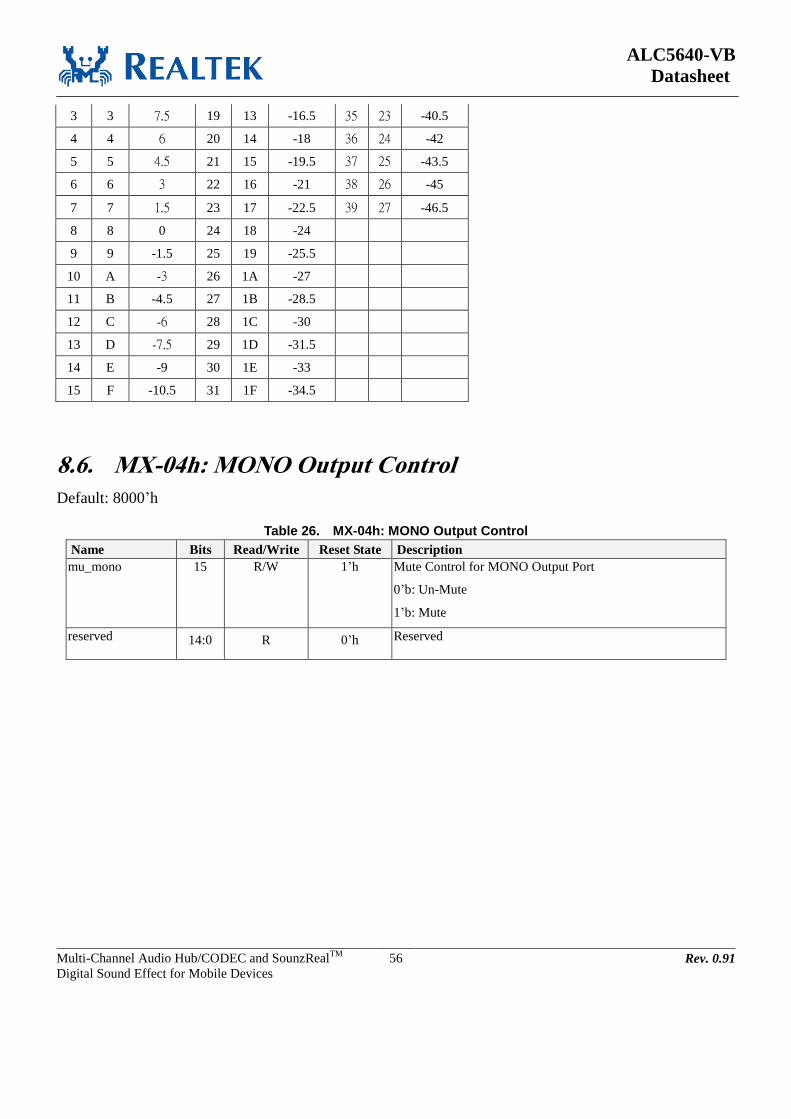
ALC5640-VB
Datasheet
Multi-Channel Audio Hub/CODEC and SounzRealTM
Digital Sound Effect for Mobile Devices
56 Rev. 0.91
3 3 7.5 19 13 -16.5 35 23 -40.5
4 4 6 20 14 -18 36 24 -42
5 5 4.5 21 15 -19.5 37 25 -43.5
6 6 3 22 16 -21 38 26 -45
7 7 1.5 23 17 -22.5 39 27 -46.5
8 8 0 24 18 -24
9 9 -1.5 25 19 -25.5
10 A -3 26 1A -27
11 B -4.5 27 1B -28.5
12 C -6 28 1C -30
13 D -7.5 29 1D -31.5
14 E -9 30 1E -33
15 F -10.5 31 1F -34.5
8.6. MX-04h: MONO Output Control
Default: 8000’h
Table 26. MX-04h: MONO Output Control
Name Bits Read/Write Reset State Description
mu_mono 15 R/W 1’h Mute Control for MONO Output Port
0’b: Un-Mute
1’b: Mute
reserved 14:0 R 0’h Reserved
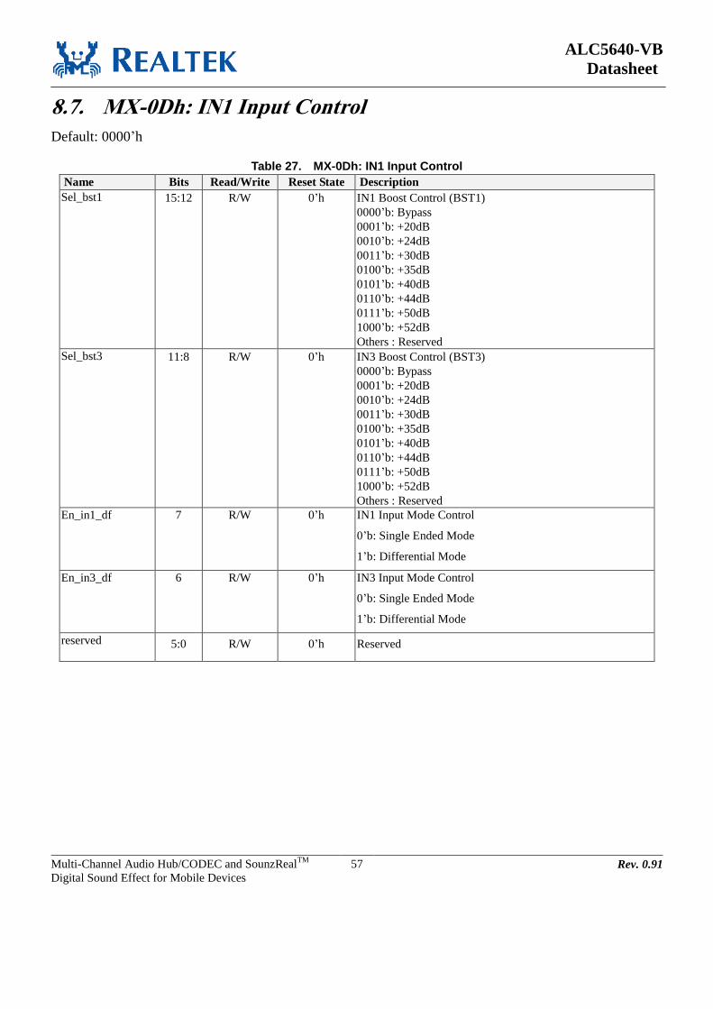
ALC5640-VB
Datasheet
Multi-Channel Audio Hub/CODEC and SounzRealTM
Digital Sound Effect for Mobile Devices
57 Rev. 0.91
8.7. MX-0Dh: IN1 Input Control
Default: 0000’h
Table 27. MX-0Dh: IN1 Input Control
Name Bits Read/Write Reset State Description
Sel_bst1 15:12 R/W 0’h IN1 Boost Control (BST1)
0000’b: Bypass
0001’b: +20dB
0010’b: +24dB
0011’b: +30dB
0100’b: +35dB
0101’b: +40dB
0110’b: +44dB
0111’b: +50dB
1000’b: +52dB
Others : Reserved
Sel_bst3 11:8 R/W 0’h IN3 Boost Control (BST3)
0000’b: Bypass
0001’b: +20dB
0010’b: +24dB
0011’b: +30dB
0100’b: +35dB
0101’b: +40dB
0110’b: +44dB
0111’b: +50dB
1000’b: +52dB
Others : Reserved
En_in1_df 7 R/W 0’h IN1 Input Mode Control
0’b: Single Ended Mode
1’b: Differential Mode
En_in3_df 6 R/W 0’h IN3 Input Mode Control
0’b: Single Ended Mode
1’b: Differential Mode
reserved 5:0 R/W 0’h Reserved
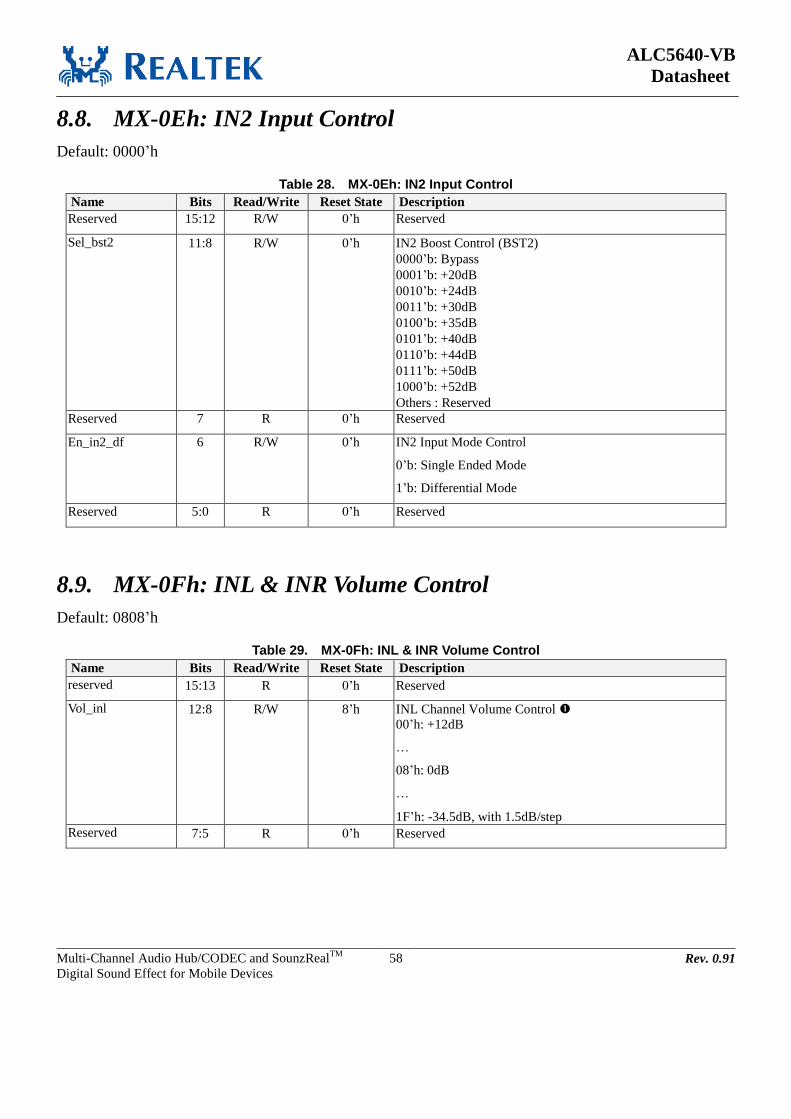
ALC5640-VB
Datasheet
Multi-Channel Audio Hub/CODEC and SounzRealTM
Digital Sound Effect for Mobile Devices
58 Rev. 0.91
8.8. MX-0Eh: IN2 Input Control
Default: 0000’h
Table 28. MX-0Eh: IN2 Input Control
Name Bits Read/Write Reset State Description
Reserved 15:12 R/W 0’h Reserved
Sel_bst2 11:8 R/W 0’h IN2 Boost Control (BST2)
0000’b: Bypass
0001’b: +20dB
0010’b: +24dB
0011’b: +30dB
0100’b: +35dB
0101’b: +40dB
0110’b: +44dB
0111’b: +50dB
1000’b: +52dB
Others : Reserved
Reserved 7 R 0’h Reserved
En_in2_df 6 R/W 0’h IN2 Input Mode Control
0’b: Single Ended Mode
1’b: Differential Mode
Reserved 5:0 R 0’h Reserved
8.9. MX-0Fh: INL & INR Volume Control
Default: 0808’h
Table 29. MX-0Fh: INL & INR Volume Control
Name Bits Read/Write Reset State Description
reserved 15:13 R 0’h Reserved
Vol_inl 12:8 R/W 8’h INL Channel Volume Control
00’h: +12dB
…
08’h: 0dB
…
1F’h: -34.5dB, with 1.5dB/step
Reserved 7:5 R 0’h Reserved

ALC5640-VB
Datasheet
Multi-Channel Audio Hub/CODEC and SounzRealTM
Digital Sound Effect for Mobile Devices
59 Rev. 0.91
Name Bits Read/Write Reset State Description
Vol_inr 4:0 R/W 8’h INR Channel Volume Control
00’h: +12dB
…
08’h: 0dB
…
1F’h: -34.5dB, with 1.5dB/step
Volume Table:
DEC HEX Boost Gain DEC HEX Boost Gain
0 0 12 16 10 -12
1 1 10.5 17 11 -13.5
2 2 9 18 12 -15
3 3 7.5 19 13 -16.5
4 4 6 20 14 -18
5 5 4.5 21 15 -19.5
6 6 3 22 16 -21
7 7 1.5 23 17 -22.5
8 8 0 24 18 -24
9 9 -1.5 25 19 -25.5
10 A -3 26 1A -27
11 B -4.5 27 1B -28.5
12 C -6 28 1C -30
13 D -7.5 29 1D -31.5
14 E -9 30 1E -33
15 F -10.5 31 1F -34.5
8.10. MX-19h: DACL1/R1 Digital Volume
Default: AFAF’h
Table 30. MX-19h: DACL1/R1 Digital Volume
Name Bits Read/Write Reset State Description
vol_dac1_l 15:8 R/W AF’h DAC1 Left Channel Digital Volume
00’h: -65.625dB
…
AF’h: 0dB, with 0.375dB/Step
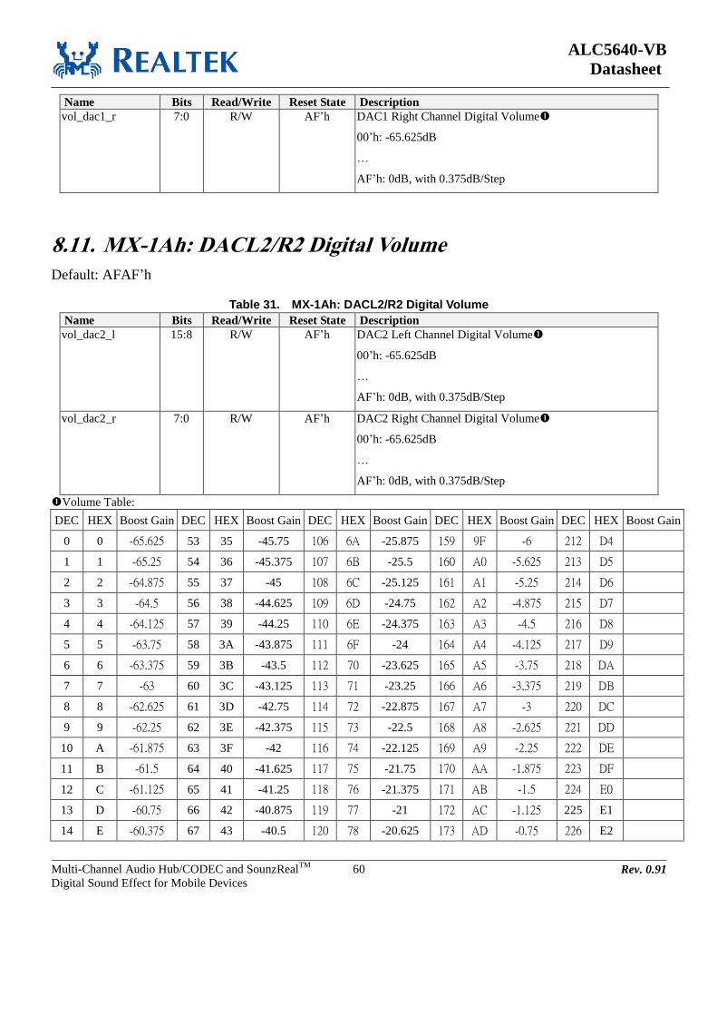
ALC5640-VB
Datasheet
Multi-Channel Audio Hub/CODEC and SounzRealTM
Digital Sound Effect for Mobile Devices
60 Rev. 0.91
Name Bits Read/Write Reset State Description
vol_dac1_r 7:0 R/W AF’h DAC1 Right Channel Digital Volume
00’h: -65.625dB
…
AF’h: 0dB, with 0.375dB/Step
8.11. MX-1Ah: DACL2/R2 Digital Volume
Default: AFAF’h
Table 31. MX-1Ah: DACL2/R2 Digital Volume
Name Bits Read/Write Reset State Description
vol_dac2_l 15:8 R/W AF’h DAC2 Left Channel Digital Volume
00’h: -65.625dB
…
AF’h: 0dB, with 0.375dB/Step
vol_dac2_r 7:0 R/W AF’h DAC2 Right Channel Digital Volume
00’h: -65.625dB
…
AF’h: 0dB, with 0.375dB/Step
Volume Table:
DEC HEX Boost Gain DEC HEX Boost Gain DEC HEX Boost Gain DEC HEX Boost Gain DEC HEX Boost Gain
0 0 -65.625 53 35 -45.75 106 6A -25.875 159 9F -6 212 D4
1 1 -65.25 54 36 -45.375 107 6B -25.5 160 A0 -5.625 213 D5
2 2 -64.875 55 37 -45 108 6C -25.125 161 A1 -5.25 214 D6
3 3 -64.5 56 38 -44.625 109 6D -24.75 162 A2 -4.875 215 D7
4 4 -64.125 57 39 -44.25 110 6E -24.375 163 A3 -4.5 216 D8
5 5 -63.75 58 3A -43.875 111 6F -24 164 A4 -4.125 217 D9
6 6 -63.375 59 3B -43.5 112 70 -23.625 165 A5 -3.75 218 DA
7 7 -63 60 3C -43.125 113 71 -23.25 166 A6 -3.375 219 DB
8 8 -62.625 61 3D -42.75 114 72 -22.875 167 A7 -3 220 DC
9 9 -62.25 62 3E -42.375 115 73 -22.5 168 A8 -2.625 221 DD
10 A -61.875 63 3F -42 116 74 -22.125 169 A9 -2.25 222 DE
11 B -61.5 64 40 -41.625 117 75 -21.75 170 AA -1.875 223 DF
12 C -61.125 65 41 -41.25 118 76 -21.375 171 AB -1.5 224 E0
13 D -60.75 66 42 -40.875 119 77 -21 172 AC -1.125 225 E1
14 E -60.375 67 43 -40.5 120 78 -20.625 173 AD -0.75 226 E2
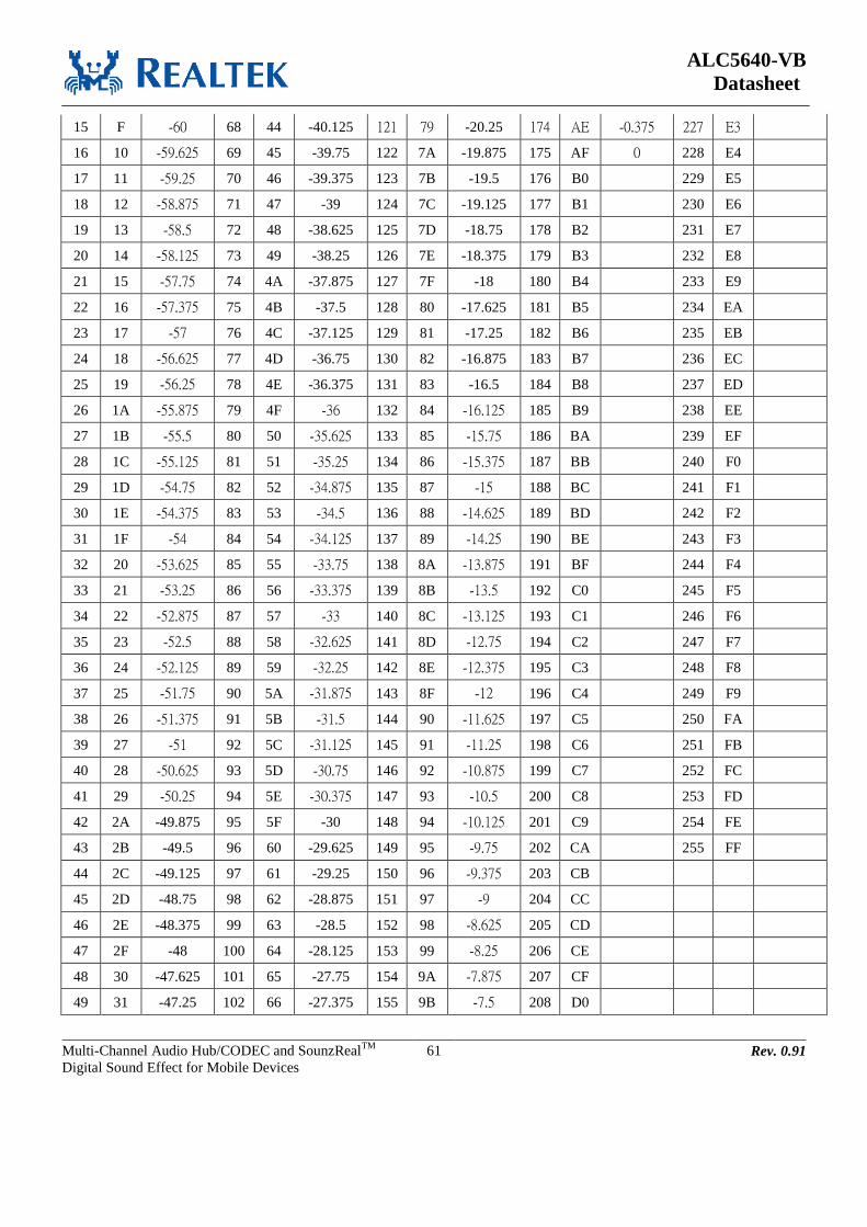
ALC5640-VB
Datasheet
Multi-Channel Audio Hub/CODEC and SounzRealTM
Digital Sound Effect for Mobile Devices
61 Rev. 0.91
15 F -60 68 44 -40.125 121 79 -20.25 174 AE -0.375 227 E3
16 10 -59.625 69 45 -39.75 122 7A -19.875 175 AF 0 228 E4
17 11 -59.25 70 46 -39.375 123 7B -19.5 176 B0 229 E5
18 12 -58.875 71 47 -39 124 7C -19.125 177 B1 230 E6
19 13 -58.5 72 48 -38.625 125 7D -18.75 178 B2 231 E7
20 14 -58.125 73 49 -38.25 126 7E -18.375 179 B3 232 E8
21 15 -57.75 74 4A -37.875 127 7F -18 180 B4 233 E9
22 16 -57.375 75 4B -37.5 128 80 -17.625 181 B5 234 EA
23 17 -57 76 4C -37.125 129 81 -17.25 182 B6 235 EB
24 18 -56.625 77 4D -36.75 130 82 -16.875 183 B7 236 EC
25 19 -56.25 78 4E -36.375 131 83 -16.5 184 B8 237 ED
26 1A -55.875 79 4F -36 132 84 -16.125 185 B9 238 EE
27 1B -55.5 80 50 -35.625 133 85 -15.75 186 BA 239 EF
28 1C -55.125 81 51 -35.25 134 86 -15.375 187 BB 240 F0
29 1D -54.75 82 52 -34.875 135 87 -15 188 BC 241 F1
30 1E -54.375 83 53 -34.5 136 88 -14.625 189 BD 242 F2
31 1F -54 84 54 -34.125 137 89 -14.25 190 BE 243 F3
32 20 -53.625 85 55 -33.75 138 8A -13.875 191 BF 244 F4
33 21 -53.25 86 56 -33.375 139 8B -13.5 192 C0 245 F5
34 22 -52.875 87 57 -33 140 8C -13.125 193 C1 246 F6
35 23 -52.5 88 58 -32.625 141 8D -12.75 194 C2 247 F7
36 24 -52.125 89 59 -32.25 142 8E -12.375 195 C3 248 F8
37 25 -51.75 90 5A -31.875 143 8F -12 196 C4 249 F9
38 26 -51.375 91 5B -31.5 144 90 -11.625 197 C5 250 FA
39 27 -51 92 5C -31.125 145 91 -11.25 198 C6 251 FB
40 28 -50.625 93 5D -30.75 146 92 -10.875 199 C7 252 FC
41 29 -50.25 94 5E -30.375 147 93 -10.5 200 C8 253 FD
42 2A -49.875 95 5F -30 148 94 -10.125 201 C9 254 FE
43 2B -49.5 96 60 -29.625 149 95 -9.75 202 CA 255 FF
44 2C -49.125 97 61 -29.25 150 96 -9.375 203 CB
45 2D -48.75 98 62 -28.875 151 97 -9 204 CC
46 2E -48.375 99 63 -28.5 152 98 -8.625 205 CD
47 2F -48 100 64 -28.125 153 99 -8.25 206 CE
48 30 -47.625 101 65 -27.75 154 9A -7.875 207 CF
49 31 -47.25 102 66 -27.375 155 9B -7.5 208 D0

ALC5640-VB
Datasheet
Multi-Channel Audio Hub/CODEC and SounzRealTM
Digital Sound Effect for Mobile Devices
62 Rev. 0.91
50 32 -46.875 103 67 -27 156 9C -7.125 209 D1
51 33 -46.5 104 68 -26.625 157 9D -6.75 210 D2
52 34 -46.125 105 69 -26.25 158 9E -6.375 211 D3
8.12. MX-1Bh: DACL2/R2 Mute/Un-Mute Control
Default: 0000’h
Table 32. MX-1Bh: DACL2/R2 Mute/Un-Mute Control
Name Bits Read/Write Reset State Description
reserved 15:14 R 0’h Reserved
Mu_dac2_l 13 R/W 0’h Mute Control for Left DAC2 Volume
0’b: Un-Mute
1’b: Mute
Mu_dac2_r 12 R/W 0’h Mute Control for Right DAC2 Volume
0’b: Un-Mute
1’b: Mute
reserved 11:0 R 0’h Reserved
8.13. MX-1Ch: Stereo ADC Digital Volume Control
Default: 2F2F’h
Table 33. MX-1Ch: Stereo ADC Digital Volume Control
Name Bits Read/Write Reset State Description
Mu_adc_vol_l 15 R/W 0’h Mute Control for Stereo ADC Left Volume Channel
0’b: Un-Mute
1’b: Mute
Ad_gain_l 14:8 R/W 2F’h Stereo ADC Left Channel Volume Control
00’h: -17.625dB
…
2F’h: 0dB
…
7F’h: +30dB, with 0.375dB/Step

ALC5640-VB
Datasheet
Multi-Channel Audio Hub/CODEC and SounzRealTM
Digital Sound Effect for Mobile Devices
63 Rev. 0.91
Mu_adc_vol_r 7 R/W 0’h Mute Control for Stereo ADC Right Volume Channel
0’b: Un-Mute
1’b: Mute
Ad_gain_r 6:0 R/W 2F’h Stereo ADC Right Channel Volume Control
00’h: -17.625dB
…
2F’h: 0dB
…
7F’h: +30dB, with 0.375dB/Step
8.14. MX-1Dh: Mono ADC Digital Volume Control
Default: 2F2F’h
Table 34. MX-1Dh: Mono ADC Digital Volume Control
Name Bits Read/Write Reset State Description
reserved 15 R 0’h Reserved
Mono_ad_gain_l 14:8 R/W 2F’h Mono ADC Left Channel Volume Control
00’h: -17.625dB
…
2F’h: 0dB
…
7F’h: +30dB, with 0.375dB/Step
reserved 7 R 0’h Reserved
Mono_ad_gain_r 6:0 R/W 2F’h Mono ADC Right Channel Volume Control
00’h: -17.625dB
…
2F’h: 0dB
…
7F’h: +30dB, with 0.375dB/Step
Volume Table: DEC HEX Boost Gain DEC HEX Boost Gain DEC HEX Boost Gain DEC HEX Boost Gain DEC HEX Boost Gain
0 0 -17.625 26 1A -7.875 52 34 1.875 78 4E 11.625 104 68 21.375
1 1 -17.25 27 1B -7.5 53 35 2.25 79 4F 12 105 69 21.75
2 2 -16.875 28 1C -7.125 54 36 2.625 80 50 12.375 106 6A 22.125
3 3 -16.5 29 1D -6.75 55 37 3 81 51 12.75 107 6B 22.5
4 4 -16.125 30 1E -6.375 56 38 3.375 82 52 13.125 108 6C 22.875
5 5 -15.75 31 1F -6 57 39 3.75 83 53 13.5 109 6D 23.25
6 6 -15.375 32 20 -5.625 58 3A 4.125 84 54 13.875 110 6E 23.625

ALC5640-VB
Datasheet
Multi-Channel Audio Hub/CODEC and SounzRealTM
Digital Sound Effect for Mobile Devices
64 Rev. 0.91
7 7 -15 33 21 -5.25 59 3B 4.5 85 55 14.25 111 6F 24
8 8 -14.625 34 22 -4.875 60 3C 4.875 86 56 14.625 112 70 24.375
9 9 -14.25 35 23 -4.5 61 3D 5.25 87 57 15 113 71 24.75
10 A -13.875 36 24 -4.125 62 3E 5.625 88 58 15.375 114 72 25.125
11 B -13.5 37 25 -3.75 63 3F 6 89 59 15.75 115 73 25.5
12 C -13.125 38 26 -3.375 64 40 6.375 90 5A 16.125 116 74 25.875
13 D -12.75 39 27 -3 65 41 6.75 91 5B 16.5 117 75 26.25
14 E -12.375 40 28 -2.625 66 42 7.125 92 5C 16.875 118 76 26.625
15 F -12 41 29 -2.25 67 43 7.5 93 5D 17.25 119 77 27
16 10 -11.625 42 2A -1.875 68 44 7.875 94 5E 17.625 120 78 27.375
17 11 -11.25 43 2B -1.5 69 45 8.25 95 5F 18 121 79 27.75
18 12 -10.875 44 2C -1.125 70 46 8.625 96 60 18.375 122 7A 28.125
19 13 -10.5 45 2D -0.75 71 47 9 97 61 18.75 123 7B 28.5
20 14 -10.125 46 2E -0.375 72 48 9.375 98 62 19.125 124 7C 28.875
21 15 -9.75 47 2F 0 73 49 9.75 99 63 19.5 125 7D 29.25
22 16 -9.375 48 30 0.375 74 4A 10.125 100 64 19.875 126 7E 29.625
23 17 -9 49 31 0.75 75 4B 10.5 101 65 20.25 127 7F 30
24 18 -8.625 50 32 1.125 76 4C 10.875 102 66 20.625
25 19 -8.25 51 33 1.5 77 4D 11.25 103 67 21
8.15. MX-1Eh: ADC Digital Boost Gain Control
Default: 0000’h
Table 35. MX-1Eh: ADC Digital Boost Gain Control
Name Bits Read/Write Reset State Description
Ad_boost_gain_l 15:14 R/W 0’h ADC Left Channel Digital Boost Gain
00’b: 0dB
01’b: 12dB
10’b: 24dB
11’b: 36dB
Ad_boost_gain_r 13:12 R/W 0’h ADC Right Channel Digital Boost Gain
00’b: 0dB
01’b: 12dB
10’b: 24dB
11’b: 36dB
reserved 11:0 R/W 0’h Reserved

ALC5640-VB
Datasheet
Multi-Channel Audio Hub/CODEC and SounzRealTM
Digital Sound Effect for Mobile Devices
65 Rev. 0.91
8.16. MX-27h: Stereo ADC Digital Mixer Control
Default: 7060’h
Table 36. MX-27h: Stereo ADC Digital Mixer Control
Name Bits Read/Write Reset State Description
reserved 15 R 0’h reserved
mu_stereo_adcl1 14 R/W 1’h Mute Control for Stereo ADC1 Left Channel
0’b: Un-Mute
1’b: Mute
mu_stereo_adcl2 13 R/W 1’h Mute Control for Stereo ADC2 Left Channel
0’b: Un-Mute
1’b: Mute
sel_stereo_adc1 12 R/W 1’h Select Control for Stereo ADC1 Source
0’b: DAC_MIXL/ DAC_MIXR
1’b: ADCL/ADCR
sel_stereo_adc2 11:10 R/W 0’h Select Control for Stereo ADC2 Source
00’b: DMIC_L1/ DMIC_R1
01’b: DMIC_L2/ DMIC_R2
10’b: DAC_MIXL/ DAC_MIXR
11’b: Reserved
reserved 9:7 R 0’h Reserved
mu_stereo_adcr1 6 R/W 1’h Mute Control for Stereo ADC1 Right Channel
0’b: Un-Mute
1’b: Mute
mu_stereo_adcr2 5 R/W 1’h Mute Control for Stereo ADC2 Right Channel
0’b: Un-Mute
1’b: Mute
reserved 4:0 R 0’h reserved
8.17. MX-28h: Mono ADC Digital Mixer Control
Default: 7070’h
Table 37. MX-28h: Mono ADC Digital Mixer Control
Name Bits Read/Write Reset State Description
reserved 15 R 0’h reserved
mu_mono_adcl1 14 R/W 1’h Mute Control for Mono ADC1 Left Channel
0’b: Un-Mute
1’b: Mute
mu_mono_adcl2 13 R/W 1’h Mute Control for Mono ADC2 Left Channel
0’b: Un-Mute
1’b: Mute
sel_mono_adcl1 12 R/W 1’h Select Control for Mono ADC1 Left Channel Source
0’b: Mono_DAC_Mixer_L
1’b: ADCL

ALC5640-VB
Datasheet
Multi-Channel Audio Hub/CODEC and SounzRealTM
Digital Sound Effect for Mobile Devices
66 Rev. 0.91
Name Bits Read/Write Reset State Description
sel_mono_adcl2 11:10 R/W 0’h Select Control for Mono ADC2 Left Channel Source
00’b: DMIC_L1
01’b: DMIC_L2
10’b: Mono_DAC_Mixer_L
11’b: Reserved
reserved 9:7 R 0’h reserved
mu_mono_adcr1 6 R/W 1’h Mute Control for Mono ADC1 Right Channel
0’b: Un-Mute
1’b: Mute
mu_mono_adcr2 5 R/W 1’h Mute Control for Mono ADC2 Right Channel
0’b: Un-Mute
1’b: Mute
sel_mono_adcr1 4 R/W 1’h Select Control for Mono ADC1 Right Channel Source
0’b: Mono_DAC_Mixer_R
1’b: ADCR
sel_mono_adcr2 3:2 R/W 0’h Select Control for Mono ADC2 Right Channel Source
00’b: DMIC_R1
01’b: DMIC_R2
10’b: Mono_DAC_Mixer_R
11’b: Reserved
reserved 1:0 R 0’h Reserved
8.18. MX-29h: Stereo ADC to DAC Digital Mixer Control
Default: 8080’h
Table 38. MX-29h: Stereo ADC to DAC Digital Mixer Control
Name Bits Read/Write Reset State Description
mu_stereo_adc_mixer
_l
15 R/W 1’h Mute Control for Stereo ADC Left Channel to DAC
0’b: Un-Mute
1’b: Mute
mu_if1_dac_l 14 R/W 0’h Mute Control for I2S-1 to DAC Left Channel
0’b: Un-Mute
1’b: Mute
reserved 13:8 R 0’h Reserved
mu_stereo_adc_mixer
_r
7 R/W 1’h Mute Control for Stereo ADC Right Channel to DAC
0’b: Un-Mute
1’b: Mute
mu_if1_dac_r 6 R/W 0’h Mute Control for I2S-1 to DAC Right Channel
0’b: Un-Mute
1’b: Mute
reserved 5:0 R 0’h reserved

ALC5640-VB
Datasheet
Multi-Channel Audio Hub/CODEC and SounzRealTM
Digital Sound Effect for Mobile Devices
67 Rev. 0.91
8.19. MX-2Ah: Stereo DAC Digital Mixer Control
Default: 5454’h
Table 39. MX-2Ah: Stereo DAC Digital Mixer Control
Name Bits Read/Write Reset State Description
reserved 15 R 0’h reserved
mu_stereo_dacl1 14 R/W 1’h Mute Control for DACL1 to Stereo DAC Left Mixer
0’b: Un-Mute
1’b: Mute
gain_dacl1_to_stereo
_l
13 R/W 0’h Gain Control for DACL1 to Stereo DAC Left Mixer
0’b: 0dB
1’b: -6dB
mu_stereo_dacl2 12 R/W 1’h Mute Control for DACL2 to Stereo DAC Left Mixer
0’b: Un-Mute
1’b: Mute
gain_dacl2_to_stereo
_l
11 R/W 0’h Gain Control for DACL2 to Stereo DAC Left Mixer
0’b: 0dB
1’b: -6dB
mu_snc_to_dac_l 10 R/W 1’h Mute Control for SNC Function to Stereo DAC Left Mixer
0’b: Un-Mute
1’b: Mute
reserved 9:7 R 0’h reserved
mu_stereo_dacr1 6 R/W 1’h Mute Control for DACR1 to Stereo DAC Right Mixer
0’b: Un-Mute
1’b: Mute
gain_dacr1_to_stereo
_r
5 R/W 0’h Gain Control for DACR1 to Stereo DAC Right Mixer
0’b: 0dB
1’b: -6dB
mu_stereo_dacr2 4 R/W 1’h Mute Control for DACR2 to Stereo DAC Right Mixer
0’b: Un-Mute
1’b: Mute
gain_dacr2_to_stereo
_r
3 R/W 0’h Gain Control for DACR2 to Stereo DAC Right Mixer
0’b: 0dB
1’b: -6dB
mu_snc_to_dac_r 2 R/W 1’h Mute Control for SNC Function to Stereo DAC Right Mixer
0’b: Un-Mute
1’b: Mute
reserved 1:0 R 0’h reserved
8.20. MX-2Bh: Mono DAC Digital Mixer Control
Default: 5454’h
Table 40. MX-2Bh: Mono DAC Digital Mixer Control
Name Bits Read/Write Reset State Description
reserved 15 R 0’h Reserved

ALC5640-VB
Datasheet
Multi-Channel Audio Hub/CODEC and SounzRealTM
Digital Sound Effect for Mobile Devices
68 Rev. 0.91
Name Bits Read/Write Reset State Description
mu_mono_l_dacl1 14 R/W 1’h Mute Control for DACL1 to Mono DAC Mixer
0’b: Un-Mute
1’b: Mute
gain_mono_l_dacl1 13 R/W 0’h Gain Control for DACL1 to Mono DAC Mixer
0’b: 0dB
1’b: -6dB
mu_mono_l_dacl2 12 R/W 1’h Mute Control for DACL2 to Mono DAC Mixer
0’b: Un-Mute
1’b: Mute
gain_mono_l_dacl2 11 R/W 0’h Gain Control for DACL2 to Mono DAC Mixer
0’b: 0dB
1’b: -6dB
mu_mono_l_dacr2 10 R/W 1’h Mute Control for DACR2 to Mono DAC Mixer
0’b: Un-Mute
1’b: Mute
gain_mono_l_dacr2 9 R/W 0’h Gain Control for DACR2 to Mono DAC Mixer
0’b: 0dB
1’b: -6dB
reserved 8:7 R 0’h Reserved
mu_mono_r_dacr1 6 R/W 1’h Mute Control for DACR1 to Mono DAC Mixer
0’b: Un-Mute
1’b: Mute
gain_mono_r_dacr1 5 R/W 0’h Gain Control for DACR1 to Mono DAC Mixer
0’b: 0dB
1’b: -6dB
mu_mono_r_dacr2 4 R/W 1’h Mute Control for DACR2 to Mono DAC Mixer
0’b: Un-Mute
1’b: Mute
gain_mono_r_dacr2 3 R/W 0’h Gain Control for DACR2 to Mono DAC Mixer
0’b: 0dB
1’b: -6dB
mu_mono_r_dacl2 2 R/W 1’h Mute Control for DACL2 to Mono DAC Mixer
0’b: Un-Mute
1’b: Mute
gain_mono_r_dacl2 1 R/W 0’h Gain Control for DACL2 to Mono DAC Mixer
0’b: 0dB
1’b: -6dB
reserved 0 R 0’h reserved
8.21. MX-2Ch: DAC Digital Mixer Control
Default: AA00’h
Table 41. MX-2Ch: DAC Digital Mixer Control
Name Bits Read/Write Reset State Description
mu_dacl1_to_dacl 15 R/W 1’h Mute Control for DACL1 to DACMIXL
0’b: Un-Mute
1’b: Mute

ALC5640-VB
Datasheet
Multi-Channel Audio Hub/CODEC and SounzRealTM
Digital Sound Effect for Mobile Devices
69 Rev. 0.91
Name Bits Read/Write Reset State Description
gain_dacl1_to_dacl 14 R/W 0’h Gain Control for DACL1 to DACMIXL
0’b: 0dB
1’b: -6dB
mu_dacl2_to_dacl 13 R/W 1’h Mute Control for DACL2 to DACMIXL
0’b: Un-Mute
1’b: Mute
gain_dacl2_to_dacl 12 R/W 0’h Gain Control for DACL2 to DACMIXL
0’b: 0dB
1’b: -6dB
mu_dacr1_to_dacr 11 R/W 1’h Mute Control for DACR1 to DACMIXR
0’b: Un-Mute
1’b: Mute
gain_dacr1_to_dacr 10 R/W 0’h Gain Control for DACR1 to DACMIXR
0’b: 0dB
1’b: -6dB
mu_dacr2_to_dacr 9 R/W 1’h Mute Control for DACR2 to DACMIXR
0’b: Un-Mute
1’b: Mute
gain_dacr2_to_dacr 8 R/W 0’h Gain Control for DACR2 to DACMIXR
0’b: 0dB
1’b: -6dB
reserved 7:0 R 0’h reserved
8.22. MX-2Fh: Interface DAC/ADC Data Control
Default: 0000’h
Table 42. MX-2Fh: Interface DAC/ADC Data Control
Name Bits Read/Write Reset State Description
sel_if1_dac_data 15:14 R/W 0’h Select Control for I2S1 DACDAT Data
00’b: Normal
01’b: Swap
10’b: Left Channel Copy to Right Channel
11’b: Right Channel Copy to Left Channel
sel_if1_adc_data 13:12 R/W 0’h Select Control for I2S1 ADCDAT Data
00’b: Normal
01’b: Swap
10’b: Left Channel Copy to Right Channel
11’b: Right Channel Copy to Left Channel
sel_if2_dac_data 11:10 R/W 0’h Select Control for I2S2 DACDAT Data
00’b: Normal
01’b: Swap
10’b: Left Channel Copy to Right Channel
11’b: Right Channel Copy to Left Channel
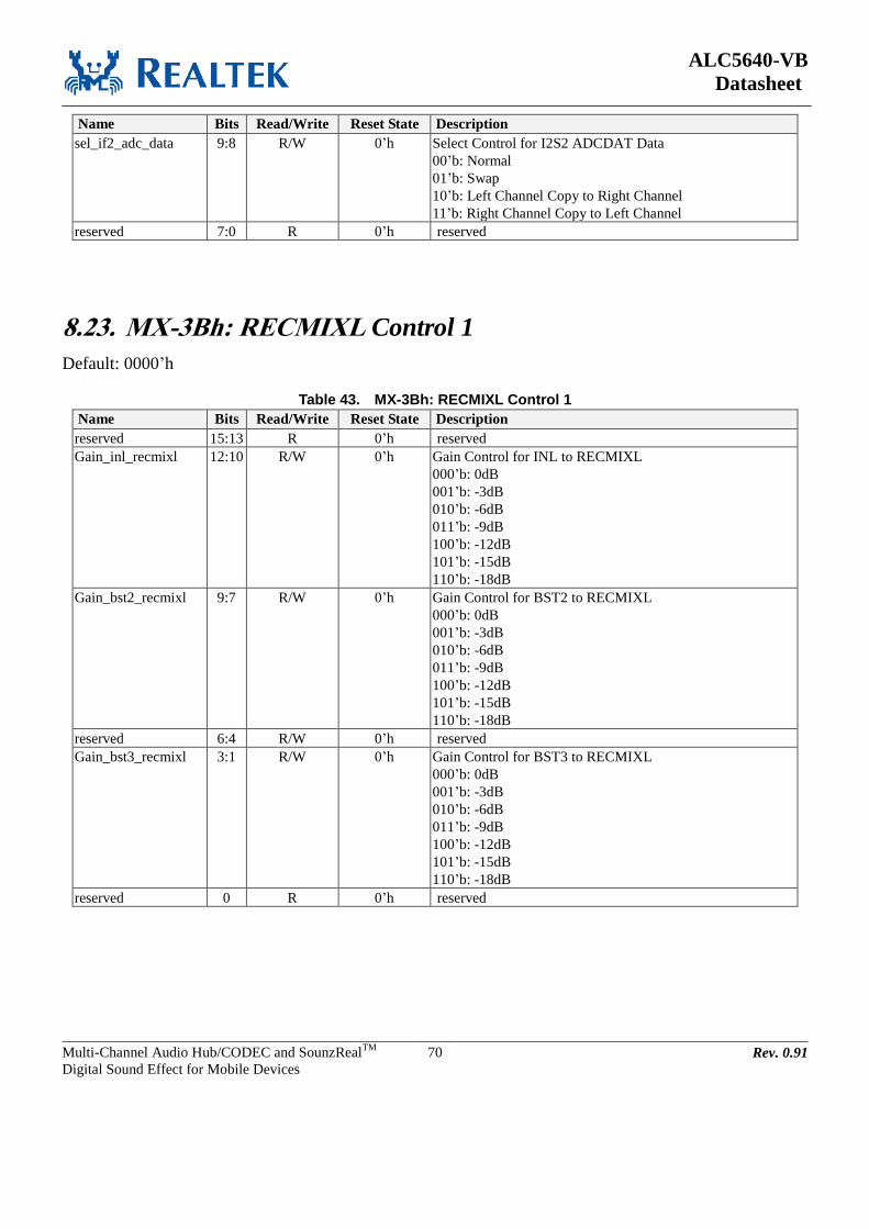
ALC5640-VB
Datasheet
Multi-Channel Audio Hub/CODEC and SounzRealTM
Digital Sound Effect for Mobile Devices
70 Rev. 0.91
Name Bits Read/Write Reset State Description
sel_if2_adc_data 9:8 R/W 0’h Select Control for I2S2 ADCDAT Data
00’b: Normal
01’b: Swap
10’b: Left Channel Copy to Right Channel
11’b: Right Channel Copy to Left Channel
reserved 7:0 R 0’h reserved
8.23. MX-3Bh: RECMIXL Control 1
Default: 0000’h
Table 43. MX-3Bh: RECMIXL Control 1
Name Bits Read/Write Reset State Description
reserved 15:13 R 0’h reserved
Gain_inl_recmixl 12:10 R/W 0’h Gain Control for INL to RECMIXL
000’b: 0dB
001’b: -3dB
010’b: -6dB
011’b: -9dB
100’b: -12dB
101’b: -15dB
110’b: -18dB
Gain_bst2_recmixl 9:7 R/W 0’h Gain Control for BST2 to RECMIXL
000’b: 0dB
001’b: -3dB
010’b: -6dB
011’b: -9dB
100’b: -12dB
101’b: -15dB
110’b: -18dB
reserved 6:4 R/W 0’h reserved
Gain_bst3_recmixl 3:1 R/W 0’h Gain Control for BST3 to RECMIXL
000’b: 0dB
001’b: -3dB
010’b: -6dB
011’b: -9dB
100’b: -12dB
101’b: -15dB
110’b: -18dB
reserved 0 R 0’h reserved
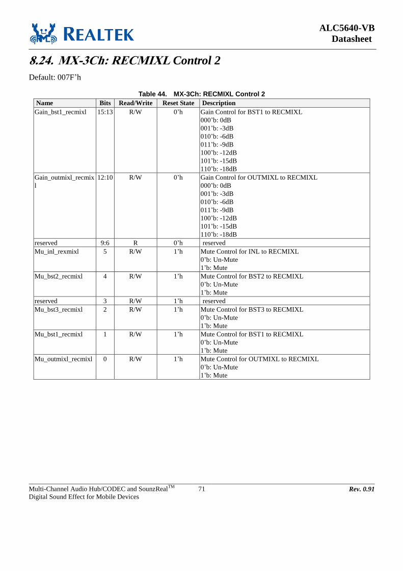
ALC5640-VB
Datasheet
Multi-Channel Audio Hub/CODEC and SounzRealTM
Digital Sound Effect for Mobile Devices
71 Rev. 0.91
8.24. MX-3Ch: RECMIXL Control 2
Default: 007F’h
Table 44. MX-3Ch: RECMIXL Control 2
Name Bits Read/Write Reset State Description
Gain_bst1_recmixl 15:13 R/W 0’h Gain Control for BST1 to RECMIXL
000’b: 0dB
001’b: -3dB
010’b: -6dB
011’b: -9dB
100’b: -12dB
101’b: -15dB
110’b: -18dB
Gain_outmixl_recmix
l
12:10 R/W 0’h Gain Control for OUTMIXL to RECMIXL
000’b: 0dB
001’b: -3dB
010’b: -6dB
011’b: -9dB
100’b: -12dB
101’b: -15dB
110’b: -18dB
reserved 9:6 R 0’h reserved
Mu_inl_rexmixl 5 R/W 1’h Mute Control for INL to RECMIXL
0’b: Un-Mute
1’b: Mute
Mu_bst2_recmixl 4 R/W 1’h Mute Control for BST2 to RECMIXL
0’b: Un-Mute
1’b: Mute
reserved 3 R/W 1’h reserved
Mu_bst3_recmixl 2 R/W 1’h Mute Control for BST3 to RECMIXL
0’b: Un-Mute
1’b: Mute
Mu_bst1_recmixl 1 R/W 1’h Mute Control for BST1 to RECMIXL
0’b: Un-Mute
1’b: Mute
Mu_outmixl_recmixl 0 R/W 1’h Mute Control for OUTMIXL to RECMIXL
0’b: Un-Mute
1’b: Mute

ALC5640-VB
Datasheet
Multi-Channel Audio Hub/CODEC and SounzRealTM
Digital Sound Effect for Mobile Devices
72 Rev. 0.91
8.25. MX-3Dh: RECMIXR Control 1
Default: 0000’h
Table 45. MX-3Dh: RECMIXR Control 1
Name Bits Read/Write Reset State Description
reserved 15:13 R/W 0’h Reserved
Gain_inr_recmixr 12:10 R/W 0’h Gain Control for INR to RECMIXR
000’b: 0dB
001’b: -3dB
010’b: -6dB
011’b: -9dB
100’b: -12dB
101’b: -15dB
110’b: -18dB
Gain_bst2_recmixr 9:7 R/W 0’h Gain Control for BST2 to RECMIXR
000’b: 0dB
001’b: -3dB
010’b: -6dB
011’b: -9dB
100’b: -12dB
101’b: -15dB
110’b: -18dB
reserved 6:4 R/W 0’h Reserved
Gain_bst3_recmixr 3:1 R/W 0’h Gain Control for BST3 to RECMIXR
000’b: 0dB
001’b: -3dB
010’b: -6dB
011’b: -9dB
100’b: -12dB
101’b: -15dB
110’b: -18dB
reserved 0 R 0’h Reserved
8.26. MX-3Eh: RECMIXR Control 2
Default: 007F’h
Table 46. MX-3Eh: RECMIXR Control 2
Name Bits Read/Write Reset State Description
Gain_bst1_recmixr 15:13 R/W 0’h Gain Control for BST1 to RECMIXR
000’b: 0dB
001’b: -3dB
010’b: -6dB
011’b: -9dB
100’b: -12dB
101’b: -15dB
110’b: -18dB
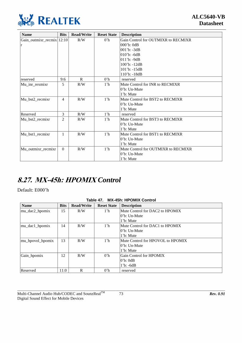
ALC5640-VB
Datasheet
Multi-Channel Audio Hub/CODEC and SounzRealTM
Digital Sound Effect for Mobile Devices
73 Rev. 0.91
Name Bits Read/Write Reset State Description
Gain_outmixr_recmix
r
12:10 R/W 0’h Gain Control for OUTMIXR to RECMIXR
000’b: 0dB
001’b: -3dB
010’b: -6dB
011’b: -9dB
100’b: -12dB
101’b: -15dB
110’b: -18dB
reserved 9:6 R 0’h reserved
Mu_inr_rexmixr 5 R/W 1’h Mute Control for INR to RECMIXR
0’b: Un-Mute
1’b: Mute
Mu_bst2_recmixr 4 R/W 1’h Mute Control for BST2 to RECMIXR
0’b: Un-Mute
1’b: Mute
Reserved 3 R/W 1’h reserved
Mu_bst2_recmixr 2 R/W 1’h Mute Control for BST3 to RECMIXR
0’b: Un-Mute
1’b: Mute
Mu_bst1_recmixr 1 R/W 1’h Mute Control for BST1 to RECMIXR
0’b: Un-Mute
1’b: Mute
Mu_outmixr_recmixr 0 R/W 1’h Mute Control for OUTMIXR to RECMIXR
0’b: Un-Mute
1’b: Mute
8.27. MX-45h: HPOMIX Control
Default: E000’h
Table 47. MX-45h: HPOMIX Control
Name Bits Read/Write Reset State Description
mu_dac2_hpomix 15 R/W 1’h Mute Control for DAC2 to HPOMIX
0’b: Un-Mute
1’b: Mute
mu_dac1_hpomix 14 R/W 1’h Mute Control for DAC1 to HPOMIX
0’b: Un-Mute
1’b: Mute
mu_hpovol_hpomix 13 R/W 1’h Mute Control for HPOVOL to HPOMIX
0’b: Un-Mute
1’b: Mute
Gain_hpomix 12 R/W 0’h Gain Control for HPOMIX
0’b: 0dB
1’b: -6dB
Reserved 11:0 R 0’h reserved
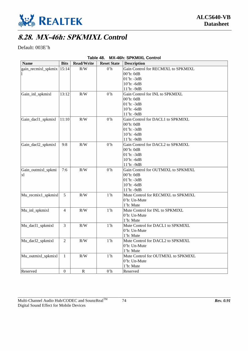
ALC5640-VB
Datasheet
Multi-Channel Audio Hub/CODEC and SounzRealTM
Digital Sound Effect for Mobile Devices
74 Rev. 0.91
8.28. MX-46h: SPKMIXL Control
Default: 003E’h
Table 48. MX-46h: SPKMIXL Control
Name Bits Read/Write Reset State Description
gain_recmixl_spkmix
l
15:14 R/W 0’h Gain Control for RECMIXL to SPKMIXL
00’b: 0dB
01’b: -3dB
10’b: -6dB
11’b: -9dB
Gain_inl_spkmixl 13:12 R/W 0’h Gain Control for INL to SPKMIXL
00’b: 0dB
01’b: -3dB
10’b: -6dB
11’b: -9dB
Gain_dacl1_spkmixl 11:10 R/W 0’h Gain Control for DACL1 to SPKMIXL
00’b: 0dB
01’b: -3dB
10’b: -6dB
11’b: -9dB
Gain_dacl2_spkmixl 9:8 R/W 0’h Gain Control for DACL2 to SPKMIXL
00’b: 0dB
01’b: -3dB
10’b: -6dB
11’b: -9dB
Gain_outmixl_spkmi
xl
7:6 R/W 0’h Gain Control for OUTMIXL to SPKMIXL
00’b: 0dB
01’b: -3dB
10’b: -6dB
11’b: -9dB
Mu_recmix1_spkmixl 5 R/W 1’h Mute Control for RECMIXL to SPKMIXL
0’b: Un-Mute
1’b: Mute
Mu_inl_spkmixl 4 R/W 1’h Mute Control for INL to SPKMIXL
0’b: Un-Mute
1’b: Mute
Mu_dacl1_spkmixl 3 R/W 1’h Mute Control for DACL1 to SPKMIXL
0’b: Un-Mute
1’b: Mute
Mu_dacl2_spkmixl 2 R/W 1’h Mute Control for DACL2 to SPKMIXL
0’b: Un-Mute
1’b: Mute
Mu_outmixl_spkmixl 1 R/W 1’h Mute Control for OUTMIXL to SPKMIXL
0’b: Un-Mute
1’b: Mute
Reserved 0 R 0’h Reserved

ALC5640-VB
Datasheet
Multi-Channel Audio Hub/CODEC and SounzRealTM
Digital Sound Effect for Mobile Devices
75 Rev. 0.91
8.29. MX-47h: SPKMIXR Control
Default: 003E’h
Table 49. MX-47h: SPKMIXR Control
Name Bits Read/Write Reset State Description
gain_recmixr_spkmix
r
15:14 R/W 0’h Gain Control for RECMIXR to SPKMIXR
00’b: 0dB
01’b: -3dB
10’b: -6dB
11’b: -9dB
Gain_inr_spkmixr 13:12 R/W 0’h Gain Control for INR to SPKMIXR
00’b: 0dB
01’b: -3dB
10’b: -6dB
11’b: -9dB
Gain_dacr1_spkmixr 11:10 R/W 0’h Gain Control for DACR1 to SPKMIXR
00’b: 0dB
01’b: -3dB
10’b: -6dB
11’b: -9dB
Gain_dacr2_spkmixr 9:8 R/W 0’h Gain Control for DACR2 to SPKMIXR
00’b: 0dB
01’b: -3dB
10’b: -6dB
11’b: -9dB
Gain_outmixr_spkmi
xr
7:6 R/W 0’h Gain Control for OUTMIXR to SPKMIXR
00’b: 0dB
01’b: -3dB
10’b: -6dB
11’b: -9dB
Mu_recmixr_spkmixr 5 R/W 1’h Mute Control for RECMIXR to SPKMIXR
0’b: Un-Mute
1’b: Mute
Mu_inr_spkmixr 4 R/W 1’h Mute Control for INR to SPKMIXR
0’b: Un-Mute
1’b: Mute
Mu_dacr1_spkmixr 3 R/W 1’h Mute Control for DACR1 to SPKMIXR
0’b: Un-Mute
1’b: Mute
Mu_dacr2_spkmixr 2 R/W 1’h Mute Control for DACR2 to SPKMIXR
0’b: Un-Mute
1’b: Mute
Mu_outmixr_spkmixr 1 R/W 1’h Mute Control for OUTMIXR to SPKMIXR
0’b: Un-Mute
1’b: Mute
Reserved 0 R 0’h Reserved
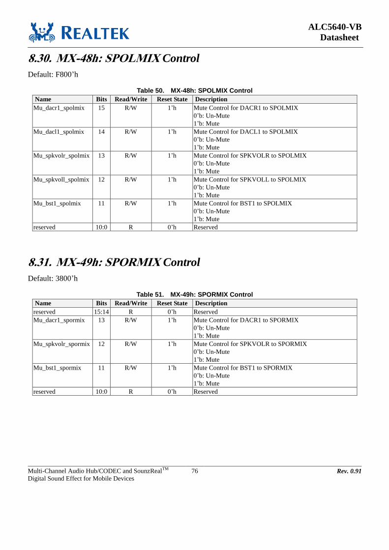
ALC5640-VB
Datasheet
Multi-Channel Audio Hub/CODEC and SounzRealTM
Digital Sound Effect for Mobile Devices
76 Rev. 0.91
8.30. MX-48h: SPOLMIX Control
Default: F800’h
Table 50. MX-48h: SPOLMIX Control
Name Bits Read/Write Reset State Description
Mu_dacr1_spolmix 15 R/W 1’h Mute Control for DACR1 to SPOLMIX
0’b: Un-Mute
1’b: Mute
Mu_dacl1_spolmix 14 R/W 1’h Mute Control for DACL1 to SPOLMIX
0’b: Un-Mute
1’b: Mute
Mu_spkvolr_spolmix 13 R/W 1’h Mute Control for SPKVOLR to SPOLMIX
0’b: Un-Mute
1’b: Mute
Mu_spkvoll_spolmix 12 R/W 1’h Mute Control for SPKVOLL to SPOLMIX
0’b: Un-Mute
1’b: Mute
Mu_bst1_spolmix 11 R/W 1’h Mute Control for BST1 to SPOLMIX
0’b: Un-Mute
1’b: Mute
reserved 10:0 R 0’h Reserved
8.31. MX-49h: SPORMIX Control
Default: 3800’h
Table 51. MX-49h: SPORMIX Control
Name Bits Read/Write Reset State Description
reserved 15:14 R 0’h Reserved
Mu_dacr1_spormix 13 R/W 1’h Mute Control for DACR1 to SPORMIX
0’b: Un-Mute
1’b: Mute
Mu_spkvolr_spormix 12 R/W 1’h Mute Control for SPKVOLR to SPORMIX
0’b: Un-Mute
1’b: Mute
Mu_bst1_spormix 11 R/W 1’h Mute Control for BST1 to SPORMIX
0’b: Un-Mute
1’b: Mute
reserved 10:0 R 0’h Reserved

ALC5640-VB
Datasheet
Multi-Channel Audio Hub/CODEC and SounzRealTM
Digital Sound Effect for Mobile Devices
77 Rev. 0.91
8.32. MX-4Ah: SPOL/RMIX Gain Control
Default: 0004’h
Table 52. MX-4Ah: SPOL/RMIX Gain Control
Name Bits Read/Write Reset State Description
reserved 15:3 R 0’h Reserved
Spk_gain_clsd 2:0 R/W 4’h Gain Control for SPOL/RMIX
000’b: -6dB (0.50x)
001’b: -4.5dB (0.60x)
010’b: -3dB (0.71x)
011’b: -1.5dB (0.84x)
100’b: 0dB (1.0x)
101’b: 0.83dB (1.1x)
110’b: 1.58dB (1.2x)
111’b: 2.28dB (1.3x)
8.33. MX-4Ch: MONOMIX Control
Default: FC00’h
Table 53. MX-4Ch: MONOMIX Control
Name Bits Read/Write Reset State Description
Mu_dacr2_monomix 15 R/W 1’h Mute Control for DACR2 to MONOMIX
0’b: Un-Mute
1’b: Mute
Mu_dacl2_monomix 14 R/W 1’h Mute Control for DACL2 to MONOMIX
0’b: Un-Mute
1’b: Mute
Mu_outvolr_monomi
x
13 R/W 1’h Mute Control for OUTVOLR to MONOMIX
0’b: Un-Mute
1’b: Mute
Mu_outvoll_monomi
x
12 R/W 1’h Mute Control for OUTVOLL to MONOMIX
0’b: Un-Mute
1’b: Mute
Mu_bst1_monomix 11 R/W 1’h Mute Control for BST1 to MONOMIX
0’b: Un-Mute
1’b: Mute
Gain_mono 10 R/W 1’h Gain Control for MONOMIX
0’b: 0dB
1’b: -6dB
reserved 9:0 R 0’h Reserved
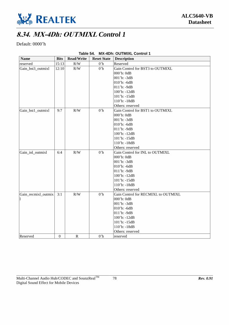
ALC5640-VB
Datasheet
Multi-Channel Audio Hub/CODEC and SounzRealTM
Digital Sound Effect for Mobile Devices
78 Rev. 0.91
8.34. MX-4Dh: OUTMIXL Control 1
Default: 0000’h
Table 54. MX-4Dh: OUTMIXL Control 1
Name Bits Read/Write Reset State Description
reserved 15:13 R/W 0’h Reserved
Gain_bst3_outmixl 12:10 R/W 0’h Gain Control for BST3 to OUTMIXL
000’b: 0dB
001’b: -3dB
010’b: -6dB
011’b: -9dB
100’b: -12dB
101’b: -15dB
110’b: -18dB
Others: reserved
Gain_bst1_outmixl 9:7 R/W 0’h Gain Control for BST1 to OUTMIXL
000’b: 0dB
001’b: -3dB
010’b: -6dB
011’b: -9dB
100’b: -12dB
101’b: -15dB
110’b: -18dB
Others: reserved
Gain_inl_outmixl 6:4 R/W 0’h Gain Control for INL to OUTMIXL
000’b: 0dB
001’b: -3dB
010’b: -6dB
011’b: -9dB
100’b: -12dB
101’b: -15dB
110’b: -18dB
Others: reserved
Gain_recmixl_outmix
l
3:1 R/W 0’h Gain Control for RECMIXL to OUTMIXL
000’b: 0dB
001’b: -3dB
010’b: -6dB
011’b: -9dB
100’b: -12dB
101’b: -15dB
110’b: -18dB
Others: reserved
Reserved 0 R 0’h reserved
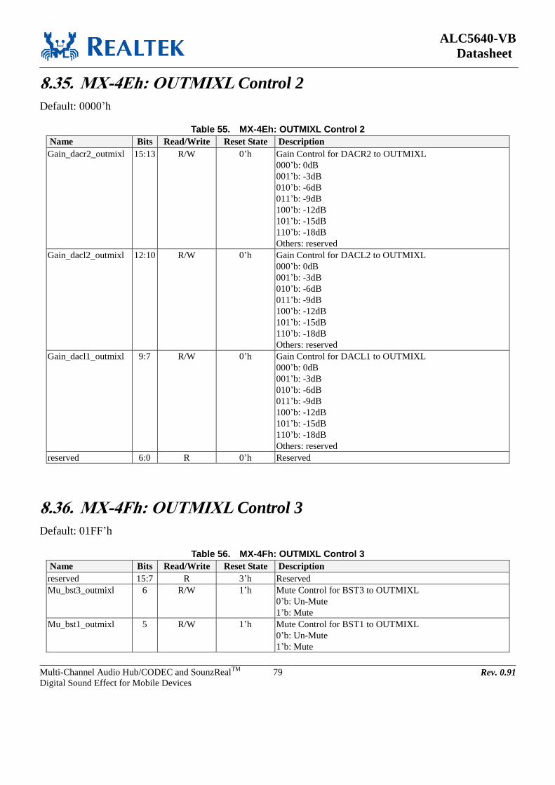
ALC5640-VB
Datasheet
Multi-Channel Audio Hub/CODEC and SounzRealTM
Digital Sound Effect for Mobile Devices
79 Rev. 0.91
8.35. MX-4Eh: OUTMIXL Control 2
Default: 0000’h
Table 55. MX-4Eh: OUTMIXL Control 2
Name Bits Read/Write Reset State Description
Gain_dacr2_outmixl 15:13 R/W 0’h Gain Control for DACR2 to OUTMIXL
000’b: 0dB
001’b: -3dB
010’b: -6dB
011’b: -9dB
100’b: -12dB
101’b: -15dB
110’b: -18dB
Others: reserved
Gain_dacl2_outmixl 12:10 R/W 0’h Gain Control for DACL2 to OUTMIXL
000’b: 0dB
001’b: -3dB
010’b: -6dB
011’b: -9dB
100’b: -12dB
101’b: -15dB
110’b: -18dB
Others: reserved
Gain_dacl1_outmixl 9:7 R/W 0’h Gain Control for DACL1 to OUTMIXL
000’b: 0dB
001’b: -3dB
010’b: -6dB
011’b: -9dB
100’b: -12dB
101’b: -15dB
110’b: -18dB
Others: reserved
reserved 6:0 R 0’h Reserved
8.36. MX-4Fh: OUTMIXL Control 3
Default: 01FF’h
Table 56. MX-4Fh: OUTMIXL Control 3
Name Bits Read/Write Reset State Description
reserved 15:7 R 3’h Reserved
Mu_bst3_outmixl 6 R/W 1’h Mute Control for BST3 to OUTMIXL
0’b: Un-Mute
1’b: Mute
Mu_bst1_outmixl 5 R/W 1’h Mute Control for BST1 to OUTMIXL
0’b: Un-Mute
1’b: Mute

ALC5640-VB
Datasheet
Multi-Channel Audio Hub/CODEC and SounzRealTM
Digital Sound Effect for Mobile Devices
80 Rev. 0.91
Name Bits Read/Write Reset State Description
Mu_inl_outmixl 4 R/W 1’h Mute Control for INL to OUTMIXL
0’b: Un-Mute
1’b: Mute
Mu_recmixl_outmixl 3 R/W 1’h Mute Control for RECMIXL to OUTMIXL
0’b: Un-Mute
1’b: Mute
Mu_dacr2_outmixl 2 R/W 1’h Mute Control for DACR2 to OUTMIXL
0’b: Un-Mute
1’b: Mute
Mu_dacl2_outmixl 1 R/W 1’h Mute Control for DACL2 to OUTMIXL
0’b: Un-Mute
1’b: Mute
Mu_dacl1_outmixl 0 R/W 1’h Mute Control for DACL1 to OUTMIXL
0’b: Un-Mute
1’b: Mute
8.37. MX-50h: OUTMIXR Control 1
Default: 0000’h
Table 57. MX-50h: OUTMIXR Control 1
Name Bits Read/Write Reset State Description
Gain_bst2_outmixr 15:13 R/W 0’h Gain Control for BST2 to OUTMIXR
000’b: 0dB
001’b: -3dB
010’b: -6dB
011’b: -9dB
100’b: -12dB
101’b: -15dB
110’b: -18dB
Others: reserved
Gain_bst3_outmixr 12:10 R/W 0’h Gain Control for BST3 to OUTMIXR
000’b: 0dB
001’b: -3dB
010’b: -6dB
011’b: -9dB
100’b: -12dB
101’b: -15dB
110’b: -18dB
Others: reserved

ALC5640-VB
Datasheet
Multi-Channel Audio Hub/CODEC and SounzRealTM
Digital Sound Effect for Mobile Devices
81 Rev. 0.91
Name Bits Read/Write Reset State Description
Gain_bst1_outmixr 9:7 R/W 0’h Gain Control for BST1 to OUTMIXR
000’b: 0dB
001’b: -3dB
010’b: -6dB
011’b: -9dB
100’b: -12dB
101’b: -15dB
110’b: -18dB
Others: reserved
Gain_inr_outmixr 6:4 R/W 0’h Gain Control for INR to OUTMIXR
000’b: 0dB
001’b: -3dB
010’b: -6dB
011’b: -9dB
100’b: -12dB
101’b: -15dB
110’b: -18dB
Others: reserved
Gain_recmixr_outmix
r
3:1 R/W 0’h Gain Control for RECMIXR to OUTMIXR
000’b: 0dB
001’b: -3dB
010’b: -6dB
011’b: -9dB
100’b: -12dB
101’b: -15dB
110’b: -18dB
Others: reserved
reserved 0 R 0’h Reserved
8.38. MX-51h: OUTMIXR Control 2
Default: 0000’h
Table 58. MX-51h: OUTMIXR Control 2
Name Bits Read/Write Reset State Description
Gain_dacl2_outmixr 15:13 R/W 0’h Gain Control for DACL2 to OUTMIXR
000’b: 0dB
001’b: -3dB
010’b: -6dB
011’b: -9dB
100’b: -12dB
101’b: -15dB
110’b: -18dB
Others: reserved
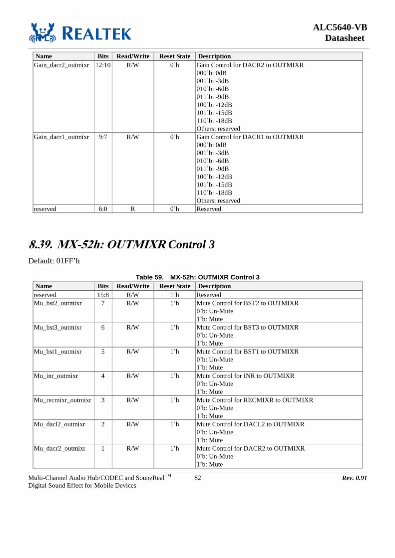
ALC5640-VB
Datasheet
Multi-Channel Audio Hub/CODEC and SounzRealTM
Digital Sound Effect for Mobile Devices
82 Rev. 0.91
Name Bits Read/Write Reset State Description
Gain_dacr2_outmixr 12:10 R/W 0’h Gain Control for DACR2 to OUTMIXR
000’b: 0dB
001’b: -3dB
010’b: -6dB
011’b: -9dB
100’b: -12dB
101’b: -15dB
110’b: -18dB
Others: reserved
Gain_dacr1_outmixr 9:7 R/W 0’h Gain Control for DACR1 to OUTMIXR
000’b: 0dB
001’b: -3dB
010’b: -6dB
011’b: -9dB
100’b: -12dB
101’b: -15dB
110’b: -18dB
Others: reserved
reserved 6:0 R 0’h Reserved
8.39. MX-52h: OUTMIXR Control 3
Default: 01FF’h
Table 59. MX-52h: OUTMIXR Control 3
Name Bits Read/Write Reset State Description
reserved 15:8 R/W 1’h Reserved
Mu_bst2_outmixr 7 R/W 1’h Mute Control for BST2 to OUTMIXR
0’b: Un-Mute
1’b: Mute
Mu_bst3_outmixr 6 R/W 1’h Mute Control for BST3 to OUTMIXR
0’b: Un-Mute
1’b: Mute
Mu_bst1_outmixr 5 R/W 1’h Mute Control for BST1 to OUTMIXR
0’b: Un-Mute
1’b: Mute
Mu_inr_outmixr 4 R/W 1’h Mute Control for INR to OUTMIXR
0’b: Un-Mute
1’b: Mute
Mu_recmixr_outmixr 3 R/W 1’h Mute Control for RECMIXR to OUTMIXR
0’b: Un-Mute
1’b: Mute
Mu_dacl2_outmixr 2 R/W 1’h Mute Control for DACL2 to OUTMIXR
0’b: Un-Mute
1’b: Mute
Mu_dacr2_outmixr 1 R/W 1’h Mute Control for DACR2 to OUTMIXR
0’b: Un-Mute
1’b: Mute

ALC5640-VB
Datasheet
Multi-Channel Audio Hub/CODEC and SounzRealTM
Digital Sound Effect for Mobile Devices
83 Rev. 0.91
Name Bits Read/Write Reset State Description
Mu_dacr1_outmixr 0 R/W 1’h Mute Control for DACR1 to OUTMIXR
0’b: Un-Mute
1’b: Mute
8.40. MX-53h: LOUTMIX Control
Default: F000’h
Table 60. MX-53h: LOUTMIX Control
Name Bits Read/Write Reset State Description
Mu_dacl1_lout 15 R/W 1’h Mute Control for DACL1 to LOUTMIX
0’b: Un-Mute
1’b: Mute
Mu_dacr1_lout 14 R/W 1’h Mute Control for DACR1 to LOUTMIX
0’b: Un-Mute
1’b: Mute
Mu_outvoll_lout 13 R/W 1’h Mute Control for OUTVOLL to LOUTMIX
0’b: Un-Mute
1’b: Mute
Mu_outvolr_lout 12 R/W 1’h Mute Control for OUTVOLR to LOUTMIX
0’b: Un-Mute
1’b: Mute
Gain_lout 11 R/W 0’h Gain Control for LOUTMIX
0’b: 0dB
1’b: -6dB
reserved 10:0 R/W 0’h Reserved
8.41. MX-61h: Power Management Control 1
Default: 0000’h
Table 61. MX-61h: Power Management Control 1
Name Bits Read/Write Reset State Description
En_i2s1 15 R/W 0’h I2S1 Digital Interface Power Control
0’b: Power Down
1’b: Power On
En_i2s2 14 R/W 0’h I2S2 Digital Interface Power Control
0’b: Power Down
1’b: Power On
reserved 13 R/W 0’h Reserved
Pow_dac_l_1 12 R/W 0’h Analog DACL1 Power Control
0’b: Power Down
1’b: Power On

ALC5640-VB
Datasheet
Multi-Channel Audio Hub/CODEC and SounzRealTM
Digital Sound Effect for Mobile Devices
84 Rev. 0.91
Name Bits Read/Write Reset State Description
Pow_dac_r_1 11 R/W 0’h Analog DACR1 Power Control
0’b: Power Down
1’b: Power On
reserved 10:8 R 0’h Reserved
Pow_dac_l_2 7 R/W 0’h Analog DACL2 Power Control
0’b: Power Down
1’b: Power On
Pow_dac_r_2 6 R/W 0’h Analog DACR2 Power Control
0’b: Power Down
1’b: Power On
reserved 5:3 R 0’h Reserved
Pow_adc_l 2 R/W 0’h Analog ADCL Power Control
0’b: Power Down
1’b: Power On
Pow_adc_r 1 R/W 0’h Analog ADCR Power Control
0’b: Power Down
1’b: Power On
Pow_clsd 0 R/W 0’h Class-D Amp Power Control
0’b: Power Down
1’b: Power On
8.42. MX-62h: Power Management Control 2
Default: 0000’h
Table 62. MX-62h: Power Management Control 2
Name Bits Read/Write Reset State Description
Pow_adc_stereo_filte
r
15 R/W 0’h Stereo ADC Digital Filter Power Control
0’b: Power Down
1’b: Power On
Pow_adc_monol_filte
r
14 R/W 0’h Mono ADC_L Digital Filter Power Control
0’b: Power Down
1’b: Power On
Pow_adc_monor_filte
r
13 R/W 0’h Mono ADC_R Digital Filter Power Control
0’b: Power Down
1’b: Power On
reserved 12:0 R 0’h Reserved

ALC5640-VB
Datasheet
Multi-Channel Audio Hub/CODEC and SounzRealTM
Digital Sound Effect for Mobile Devices
85 Rev. 0.91
8.43. MX-63h: Power Management Control 3
Default: 00C0’h
Table 63. MX-63h: Power Management Control 3
Name Bits Read/Write Reset State Description
Pow_vref1 15 R/W 0’h VREF1 Power Control
0’b: Power Down
1’b: Power On
En_fastb1 14 R/W 0’h VREF1 Fast Mode Control
0’b: Fast VREF
1’b: Slow VREF, (For good analog performance)
Pow_main_bias 13 R/W 0’h MBIAS Power Control
0’b: Power Down
1’b: Power On
Pow_lout 12 R/W 0’h LOUTMIX Power Control
0’b: Power Down
1’b: Power On
Pow_bg_bias 11 R/W 0’h MBIAS Bandgap Power Control
0’b: Power Down
1’b: Power On
Pow_mono 10 R/W 0’h MONOMIX Power Control
0’b: Power Down
1’b: Power On
reserved 9 R 0’h Reserved
En_amp_mono 8 R/W 0’h Mono Amp Power Control
0’b: Power Down
1’b: Power On
En_l_hp 7 R/W 1’h Left Headphone Amp Power Control
0’b: Power Down
1’b: Power On
En_r_hp 6 R/W 1’h Right Headphone Amp Power Control
0’b: Power Down
1’b: Power On
En_amp_hp 5 R/W 0’h Improve HP Amp Driving
0’b: Disable
1’b: Enable
Pow_vref2 4 R/W 0’h VREF2 Power Control
0’b: Power Down
1’b: Power On
En_fastb2 3 R/W 0’h VREF2 Fast Mode Control
0’b: Fast VREF
1’b: Slow VREF, (For good analog performance)
Pow_ldo2 2 R/W 0’h LDO2 Power Control
0’b: Power Down
1’b: Power On
reserved 1:0 R 0’h Reserved

ALC5640-VB
Datasheet
Multi-Channel Audio Hub/CODEC and SounzRealTM
Digital Sound Effect for Mobile Devices
86 Rev. 0.91
8.44. MX-64h: Power Management Control 4
Default: 0000’h
Table 64. MX-64h: Power Management Control 4
Name Bits Read/Write Reset State Description
Pow_bst1 15 R/W 0’h MIC BST1 Power Control
0’b: Power Down
1’b: Power On
Pow_bst3 14 R/W 0’h MIC BST3 Power Control
0’b: Power Down
1’b: Power On
reserved 13 R/W 0’h reserved
Pow_bst2 12 R/W 0’h MIC BST2 Power Control
0’b: Power Down
1’b: Power On
Pow_micbias1 11 R/W 0’h MICBIAS1 Power Control
0’b: Power Down
1’b: Power On
reserved 10 R/W 0’h reserved
Pow_pll 9 R/W 0’h PLL Power Control
0’b: Power Down
1’b: Power On
reserved 8:0 R 0’h Reserved
8.45. MX-65h: Power Management Control 5
Default: 0000’h
Table 65. MX-65h: Power Management Control 5
Name Bits Read/Write Reset State Description
Pow_outmixl 15 R/W 0’h OUTMIXL Power Control
0’b: Power Down
1’b: Power On
Pow_outmixr 14 R/W 0’h OUTMIXR Power Control
0’b: Power Down
1’b: Power On
Pow_spkmixl 13 R/W 0’h SPKMIXL Power Control
0’b: Power Down
1’b: Power On
Pow_spkmixr 12 R/W 0’h SPKMIXR Power Control
0’b: Power Down
1’b: Power On
Pow_recmixl 11 R/W 0’h RECMIXL Power Control
0’b: Power Down
1’b: Power On

ALC5640-VB
Datasheet
Multi-Channel Audio Hub/CODEC and SounzRealTM
Digital Sound Effect for Mobile Devices
87 Rev. 0.91
Name Bits Read/Write Reset State Description
Pow_recmixr 10 R/W 0’h RECMIXR Power Control
0’b: Power Down
1’b: Power On
reserved 9:0 R 0’h Reserved
8.46. MX-66h: Power Management Control 6
Default: 0000’h
Table 66. MX-66h: Power Management Control 6
Name Bits Read/Write Reset State Description
Pow_spkvoll 15 R/W 0’h SPKVOLL Power Control
0’b: Power Down
1’b: Power On
Pow_spkvolr 14 R/W 0’h SPKVOLR power Control
0’b: Power Down
1’b: Power On
Pow_outvoll 13 R/W 0’h OUTVOLL Power Control
0’b: Power Down
1’b: Power On
Pow_outvolr 12 R/W 0’h OUTVOLR Power Control
0’b: Power Down
1’b: Power On
Pow_hpovoll 11 R/W 0’h HPOVOLL Power Control
0’b: Power Down
1’b: Power On
Pow_hpovolr 10 R/W 0’h HPOVOLR Power Control
0’b: Power Down
1’b: Power On
Pow_inlvol 9 R/W 0’h INLVOL Power Control
0’b: Power Down
1’b: Power On
Pow_inrvol 8 R/W 0’h INRVOL Power Control
0’b: Power Down
1’b: Power On
reserved 7:0 R 0’h Reserved
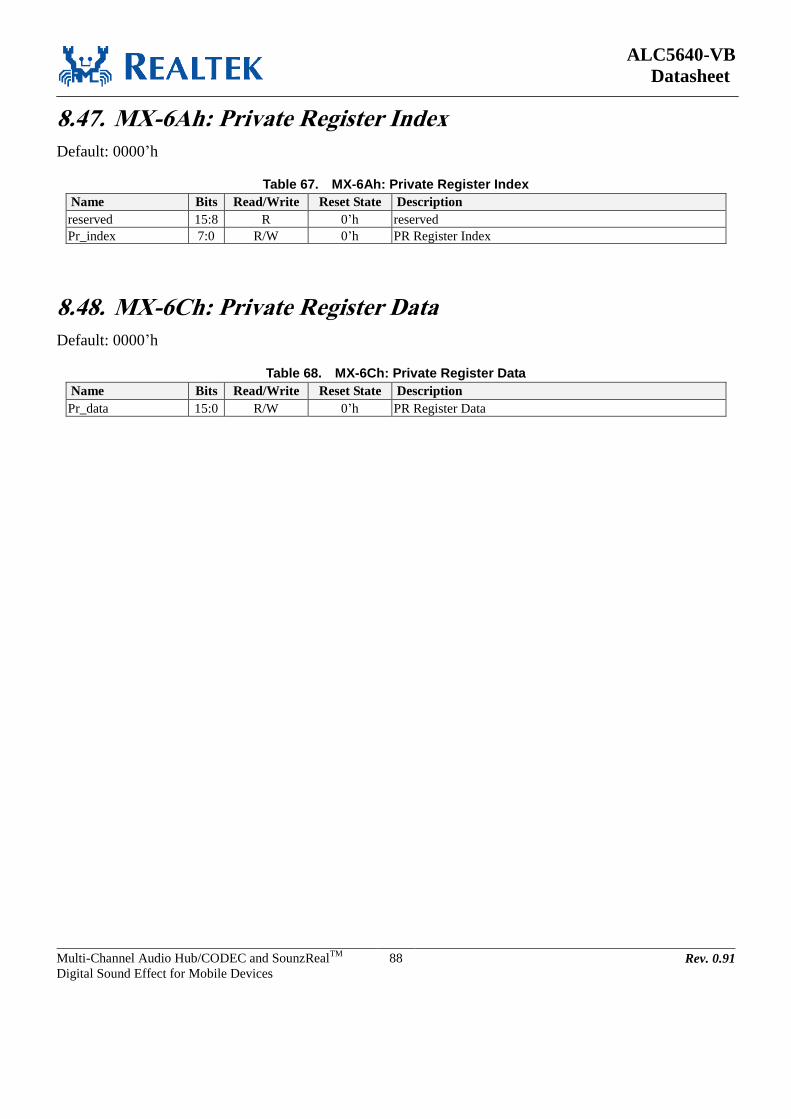
ALC5640-VB
Datasheet
Multi-Channel Audio Hub/CODEC and SounzRealTM
Digital Sound Effect for Mobile Devices
88 Rev. 0.91
8.47. MX-6Ah: Private Register Index
Default: 0000’h
Table 67. MX-6Ah: Private Register Index
Name Bits Read/Write Reset State Description
reserved 15:8 R 0’h reserved
Pr_index 7:0 R/W 0’h PR Register Index
8.48. MX-6Ch: Private Register Data
Default: 0000’h
Table 68. MX-6Ch: Private Register Data
Name Bits Read/Write Reset State Description
Pr_data 15:0 R/W 0’h PR Register Data
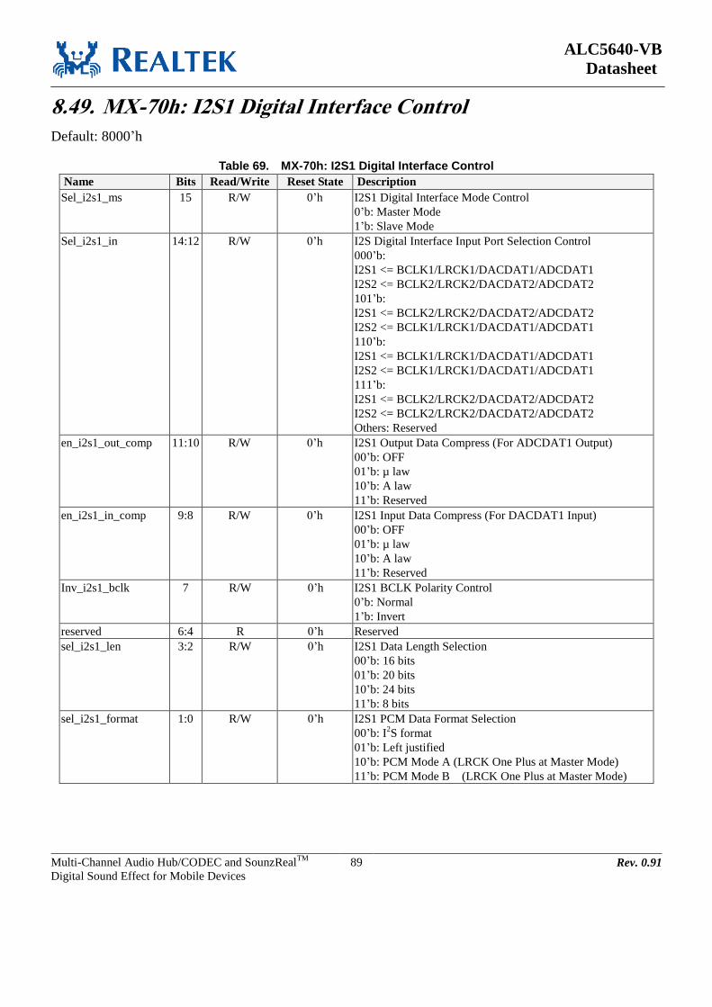
ALC5640-VB
Datasheet
Multi-Channel Audio Hub/CODEC and SounzRealTM
Digital Sound Effect for Mobile Devices
89 Rev. 0.91
8.49. MX-70h: I2S1 Digital Interface Control
Default: 8000’h
Table 69. MX-70h: I2S1 Digital Interface Control
Name Bits Read/Write Reset State Description
Sel_i2s1_ms 15 R/W 0’h I2S1 Digital Interface Mode Control
0’b: Master Mode
1’b: Slave Mode
Sel_i2s1_in 14:12 R/W 0’h I2S Digital Interface Input Port Selection Control
000’b:
I2S1 <= BCLK1/LRCK1/DACDAT1/ADCDAT1
I2S2 <= BCLK2/LRCK2/DACDAT2/ADCDAT2
101’b:
I2S1 <= BCLK2/LRCK2/DACDAT2/ADCDAT2
I2S2 <= BCLK1/LRCK1/DACDAT1/ADCDAT1
110’b:
I2S1 <= BCLK1/LRCK1/DACDAT1/ADCDAT1
I2S2 <= BCLK1/LRCK1/DACDAT1/ADCDAT1
111’b:
I2S1 <= BCLK2/LRCK2/DACDAT2/ADCDAT2
I2S2 <= BCLK2/LRCK2/DACDAT2/ADCDAT2
Others: Reserved
en_i2s1_out_comp 11:10 R/W 0’h I2S1 Output Data Compress (For ADCDAT1 Output)
00’b: OFF
01’b: µ law
10’b: A law
11’b: Reserved
en_i2s1_in_comp 9:8 R/W 0’h I2S1 Input Data Compress (For DACDAT1 Input)
00’b: OFF
01’b: µ law
10’b: A law
11’b: Reserved
Inv_i2s1_bclk 7 R/W 0’h I2S1 BCLK Polarity Control
0’b: Normal
1’b: Invert
reserved 6:4 R 0’h Reserved
sel_i2s1_len 3:2 R/W 0’h I2S1 Data Length Selection
00’b: 16 bits
01’b: 20 bits
10’b: 24 bits
11’b: 8 bits
sel_i2s1_format 1:0 R/W 0’h I2S1 PCM Data Format Selection
00’b: I2S format
01’b: Left justified
10’b: PCM Mode A (LRCK One Plus at Master Mode)
11’b: PCM Mode B (LRCK One Plus at Master Mode)
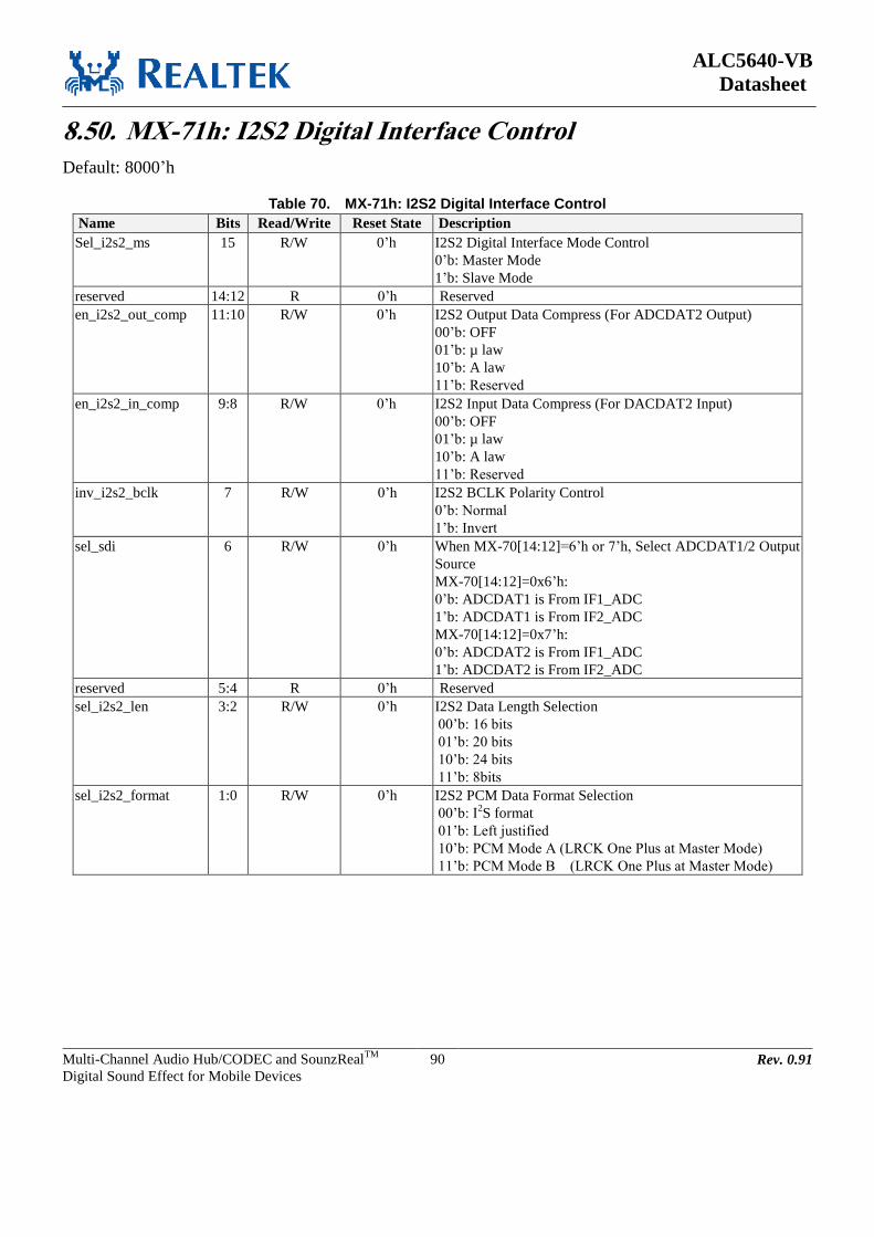
ALC5640-VB
Datasheet
Multi-Channel Audio Hub/CODEC and SounzRealTM
Digital Sound Effect for Mobile Devices
90 Rev. 0.91
8.50. MX-71h: I2S2 Digital Interface Control
Default: 8000’h
Table 70. MX-71h: I2S2 Digital Interface Control
Name Bits Read/Write Reset State Description
Sel_i2s2_ms 15 R/W 0’h I2S2 Digital Interface Mode Control
0’b: Master Mode
1’b: Slave Mode
reserved 14:12 R 0’h Reserved
en_i2s2_out_comp 11:10 R/W 0’h I2S2 Output Data Compress (For ADCDAT2 Output)
00’b: OFF
01’b: µ law
10’b: A law
11’b: Reserved
en_i2s2_in_comp 9:8 R/W 0’h I2S2 Input Data Compress (For DACDAT2 Input)
00’b: OFF
01’b: µ law
10’b: A law
11’b: Reserved
inv_i2s2_bclk 7 R/W 0’h I2S2 BCLK Polarity Control
0’b: Normal
1’b: Invert
sel_sdi 6 R/W 0’h When MX-70[14:12]=6’h or 7’h, Select ADCDAT1/2 Output
Source
MX-70[14:12]=0x6’h:
0’b: ADCDAT1 is From IF1_ADC
1’b: ADCDAT1 is From IF2_ADC
MX-70[14:12]=0x7’h:
0’b: ADCDAT2 is From IF1_ADC
1’b: ADCDAT2 is From IF2_ADC
reserved 5:4 R 0’h Reserved
sel_i2s2_len 3:2 R/W 0’h I2S2 Data Length Selection
00’b: 16 bits
01’b: 20 bits
10’b: 24 bits
11’b: 8bits
sel_i2s2_format 1:0 R/W 0’h I2S2 PCM Data Format Selection
00’b: I2S format
01’b: Left justified
10’b: PCM Mode A (LRCK One Plus at Master Mode)
11’b: PCM Mode B (LRCK One Plus at Master Mode)

ALC5640-VB
Datasheet
Multi-Channel Audio Hub/CODEC and SounzRealTM
Digital Sound Effect for Mobile Devices
91 Rev. 0.91
8.51. MX-73h: ADC/DAC Clock Control 1
Default: 1114’h
Table 71. MX-73h: ADC/DAC Clock Control 1
Name Bits Read/Write Reset State Description
sel_i2s_bclk_ms1 15 R/W 0’h I2S1 Master Mode Clock Relative of BCLK and LRCK
0’b: 16Bits (32FS)
1’b: 32Bits (64FS) sel_i2s_pre_div1 14:12 R/W 1’h I2S Clock Pre-Divider 1
000’b: ÷ 1
001’b: ÷ 2
010’b: ÷ 3
011’b: ÷ 4
100’b: ÷ 6
101’b: ÷ 8
110’b: ÷ 12
111’b: ÷ 16
sel_i2s_bclk_ms2 11 R/W 0’h I2S2 Master Mode Clock Relative of BCLK and LRCK
0’b: 16Bits (32FS)
1’b: 32Bits (64FS) sel_i2s_pre_div2 10:8 R/W 1’h I2S Pre-Divider 2
000’b: ÷ 1
001’b: ÷ 2
010’b: ÷ 3
011’b: ÷ 4
100’b: ÷ 6
101’b: ÷ 8
110’b: ÷ 12
111’b: ÷ 16
reserved 7:4 R/W 1’h Reserved sel_dac_osr 3:2 R/W 1’h Stereo DAC Over Sample Rate Select
00’b: 128Fs
01’b: 64Fs
10’b: 32Fs
11’b: 16Fs
sel_adc_osr 1:0 R/W 0’h Stereo ADC Over Sample Rate Select
00’b: 128Fs
01’b: 64Fs
10’b: 32Fs
11’b: 16Fs

ALC5640-VB
Datasheet
Multi-Channel Audio Hub/CODEC and SounzRealTM
Digital Sound Effect for Mobile Devices
92 Rev. 0.91
8.52. MX-74h: ADC/DAC Clock Control 2
Default: 0C00’h
Table 72. MX-74h: ADC/DAC Clock Control 2
Name Bits Read/Write Reset State Description
sel_da_osr_mono_l 15:14 R/W 0’h Mono DACL Over Sample Rate Select
00’b: 128Fs
01’b: 64Fs
10’b: 32Fs
11’b: 16Fs
sel_da_osr_mono_r 13:12 R/W 0’h Mono DACR Over Sample Rate Select
00’b: 128Fs
01’b: 64Fs
10’b: 32Fs
11’b: 16Fs
reserved 11:0 R/W C00’h Reserved
8.53. MX-75h: Digital Microphone Control
Default: 1D00’h
Table 73. MX-75h: Digital Microphone Control
Name Bits Read/Write Reset State Description
en_dmic1 15 R/W 0’h Enable DMIC1 Interface
0’b: Disable
1’b: Enable (Output DMIC clock)
en_dmic2 14 R/W 0’h Enable DMIC2 Interface
0’b: Disable
1’b: Enable (Output DMIC clock)
sel_dmic1_l_edge 13 R/W 0’h DMIC1 Left Channel Source Control
0’b: Latch from falling edge
1’b: Latch from rising edge
sel_dmic1_r_edge 12 R/W 1’h DMIC1 Right Channel Source Control
0’b: Latch from falling edge
1’b: Latch from rising edge
reserved 11:10 R/W 3’h Reserved
sel_dmic2_l_edge 9 R/W 0’h DMIC2 Left Channel Source Control
0’b: Latch from falling edge
1’b: Latch from rising edge
sel_dmic2_r_edge 8 R/W 1’h DMIC2 Right Channel Source Control
0’b: Latch from falling edge
1’b: Latch from rising edge

ALC5640-VB
Datasheet
Multi-Channel Audio Hub/CODEC and SounzRealTM
Digital Sound Effect for Mobile Devices
93 Rev. 0.91
Name Bits Read/Write Reset State Description
sel_dmic_clk 7:5 R/W 0’h DMIC Clock Rate Control
000’b: 256*fs/2
001’b: 256*fs/3
010’b: 256*fs/4
011’b: 256*fs/6
100’b: 256*fs/8
101’b: 256*fs/12
reserved 4:0 R 0’h Reserved
8.54. MX-80h: Global Clock Control
Default: 0000’h
Table 74. MX-80h: Global Clock Control
Name Bits Read/Write Reset State Description
sel_sysclk1 15:14 R/W 0’h System Clock Source MUX Control
00’b: MCLK
01’b: PLL
10’b: Reserved
11’b: Reserved
sel_pll_sour 13:12 R/W 0’h PLL Source Selection
00’b: From MCLK
01’b: From BCLK1
10’b: From BCLK2
11’b: Reserved
reserved 11:4 R 0’h Reserved
sel_pll_pre_div 3 R/W 0’h PLL Pre-Divider
0’b: ÷ 1
1’b: ÷ 2
reserved 2:0 R 0’h Reserved
8.55. MX-81h: PLL Control 1
Default: 0000’h
Table 75. MX-81h: PLL Control 1
Name Bits Read/Write Reset State Description
Pll_n_code 15:7 R/W 0’h PLL N[8:0] Code
000000000’b: Div 2
000000001’b: Div 3
…
111111111’b: Div 513
Reserved 6:5 R 0’h Reserved
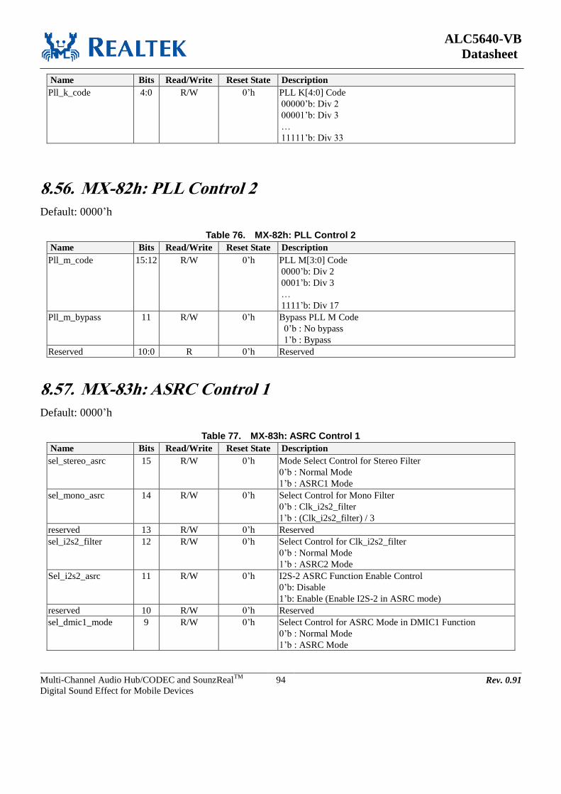
ALC5640-VB
Datasheet
Multi-Channel Audio Hub/CODEC and SounzRealTM
Digital Sound Effect for Mobile Devices
94 Rev. 0.91
Name Bits Read/Write Reset State Description
Pll_k_code 4:0 R/W 0’h PLL K[4:0] Code
00000’b: Div 2
00001’b: Div 3
…
11111’b: Div 33
8.56. MX-82h: PLL Control 2
Default: 0000’h
Table 76. MX-82h: PLL Control 2
Name Bits Read/Write Reset State Description
Pll_m_code 15:12 R/W 0’h PLL M[3:0] Code
0000’b: Div 2
0001’b: Div 3
…
1111’b: Div 17
Pll_m_bypass 11 R/W 0’h Bypass PLL M Code
0’b : No bypass
1’b : Bypass
Reserved 10:0 R 0’h Reserved
8.57. MX-83h: ASRC Control 1
Default: 0000’h
Table 77. MX-83h: ASRC Control 1
Name Bits Read/Write Reset State Description
sel_stereo_asrc 15 R/W 0’h Mode Select Control for Stereo Filter
0’b : Normal Mode
1’b : ASRC1 Mode
sel_mono_asrc 14 R/W 0’h Select Control for Mono Filter
0’b : Clk_i2s2_filter
1’b : (Clk_i2s2_filter) / 3
reserved 13 R/W 0’h Reserved
sel_i2s2_filter 12 R/W 0’h Select Control for Clk_i2s2_filter
0’b : Normal Mode
1’b : ASRC2 Mode
Sel_i2s2_asrc 11 R/W 0’h I2S-2 ASRC Function Enable Control
0’b: Disable
1’b: Enable (Enable I2S-2 in ASRC mode)
reserved 10 R/W 0’h Reserved
sel_dmic1_mode 9 R/W 0’h Select Control for ASRC Mode in DMIC1 Function
0’b : Normal Mode
1’b : ASRC Mode

ALC5640-VB
Datasheet
Multi-Channel Audio Hub/CODEC and SounzRealTM
Digital Sound Effect for Mobile Devices
95 Rev. 0.91
Name Bits Read/Write Reset State Description
sel_dmic2_mode 8 R/W 0’h Select Control for ASRC Mode in DMIC2 Function
0’b : Normal Mode
1’b : ASRC Mode
reserved 7:0 R 0’h Reserved
8.58. MX-84h: ASRC Control 2
Default: 0000’h
Table 78. MX-84h: ASRC Control 2
Name Bits Read/Write Reset State Description
sel_mono_da_l_mode 15 R/W 0’h Select Control for DA_L Mono Filter
0’b: Normal Mode
1’b: ASRC Mode
sel_mono_da_r_mode 14 R/W 0’h Select Control for DA_R Mono Filter
0’b: Normal Mode
1’b: ASRC Mode
sel_mono_ad_l_mode 13 R/W 0’h Select Control for AD_L Mono Filter
0’b: Normal Mode
1’b: ASRC Mode
sel_mono_ad_r_mode 12 R/W 0’h Select Control for AD_R Mono Filter
0’b: Normal Mode
1’b: ASRC Mode
sel_adc_mode 11 R/W 0’h Select Control for ADC Stereo Filter
0’b: Normal Mode
1’b: ASRC Mode
reserved 10:6 R/W 0’h Reserved
sel_stereo_dac_mode 5 R/W 0’h Select Control for DAC Stereo Filter
0’b : Normal Mode
1’b : ASRC Mode
En_i2s1_asrcin_auto_
det
4 R/W 0’h Automatically Detect I2S1 Input Sample Rate
0’b : Disable
1’b : Enable
En_i2s2_asrcin_auto_
det
3 R/W 0’h Automatically Detect I2S2 Input Sample Rate
0’b : Disable
1’b : Enable
reserved 2 R/W 0’h Reserved
Sel_asrcin_256fs_sys 1:0 R/W 0’h Select for Pre-System Clock
00’b: 512*48k
01’b: 1024*48k
10’b: 2048*48k
11’b: Reserved

ALC5640-VB
Datasheet
Multi-Channel Audio Hub/CODEC and SounzRealTM
Digital Sound Effect for Mobile Devices
96 Rev. 0.91
8.59. MX-85h: ASRC Control 3
Default: 0008’h
Table 79. MX-85h: ASRC Control 3
Name Bits Read/Write Reset State Description
I2s1_asrcin_fsi_rate_
manual
15:12 R/W 0’h Set I2S1 Input Sample Rate
0’h: 48K 1’h: 96k 2’h: 192k 3’h: 32K
4’h: 48K 5’h: 96k 6’h: 192k 7’h: 32K
8’h: 48K 9’h: 96k A’h: 192k B’h: reserve
C’h: 22.05K D’h: reserve E’h: 11.025K F’h: reserve
I2s2_asrcin_fsi_rate_
manual
11:8 R/W 0’h Set I2S2 Input Sample Rate
0’h: 48K 1’h: 96k 2’h: 192k 3’h: 32K
4’h: 48K 5’h: 96k 6’h: 192k 7’h: 32K
8’h: 48K 9’h: 96k A’h: 192k B’h: reserve
C’h: 22.05K D’h: reserve E’h: 11.025K F’h: reserve
reserved 7:0 R/W 0’h Reserved
8.60. MX-89h: ASRC Control 4
Default: 0000’h
Table 80. MX-89h: ASRC Control 4
Name Bits Read/Write Reset State Description
reserved 15 R 0’h Reserved
i2s1_track_prediv 14:12 R/W 0’h Set I2S1 Clock Division for Stereo Filter
000’b: div1 001’b: div2 010’b: div3
011’b: div4 100’b: div6 101’b: div8
110’b: div12 111’b: div16
reserved 11 R 0’h Reserved
i2s2_track_prediv 10:8 R/W 0’h Set I2S2 Clock Division for Mono Filter
000’b: div1 001’b: div2 010’b: div3
011’b: div4 100’b: div6 101’b: div8
110’b: div12 111’b: div16
reserved 7:0 R/W 0’h Reserved

ALC5640-VB
Datasheet
Multi-Channel Audio Hub/CODEC and SounzRealTM
Digital Sound Effect for Mobile Devices
97 Rev. 0.91
8.61. MX-8Ah: ASRC Control 5
Default: 0000’h
Table 81. MX-8Ah: ASRC Control 5
Name Bits Read/Write Reset State Description
asrcin_fsi1_rate 15:12 R 0’h I2S1 Sample Rate Detection
0000'b: 48k, 44.1k, 32k
0001'b: 96k, 88.2k
0010'b: 192k, 176.4k
0100'b: 24k, 22.05k, 16k
0110'b: 12k, 11.025k, 8k
asrcin_fsi2_rate 11:8 R 0’h I2S2 Sample Rate Detection
0000'b: 48k, 44.1k, 32k
0001'b: 96k, 88.2k
0010'b: 192k, 176.4k
0100'b: 24k, 22.05k, 16k
0110'b: 12k, 11.025k, 8k
reserved 7:0 R 0’h Reserved
8.62. MX-8Ch: Class-D Amp OC Control
Default: 0228’h
Table 82. MX-8Ch: Class-D Amp OC Control
Name Bits Read/Write Reset State Description
reserved 15:10 R 0’h Reserved
Pow_ocp_clsd 9 R/W 1’h Class-D Amp Over-Current Sensor Power Control
0’b: Power Down
1’b: Power On
Autopd_clsd 8 R/W 0’h Class-D Amp Auto Power Down Control When OC
0’b: Disable
1’b: Enable
reserved 7:0 R/W 28’h Reserved
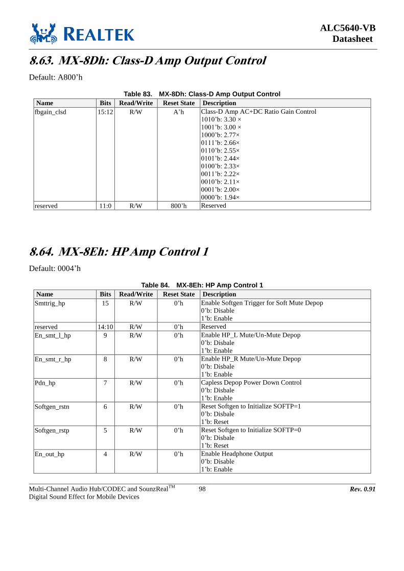
ALC5640-VB
Datasheet
Multi-Channel Audio Hub/CODEC and SounzRealTM
Digital Sound Effect for Mobile Devices
98 Rev. 0.91
8.63. MX-8Dh: Class-D Amp Output Control
Default: A800’h
Table 83. MX-8Dh: Class-D Amp Output Control
Name Bits Read/Write Reset State Description
fbgain_clsd 15:12 R/W A’h Class-D Amp AC+DC Ratio Gain Control
1010’b: 3.30 ×
1001’b: 3.00 ×
1000’b: 2.77×
0111’b: 2.66×
0110’b: 2.55×
0101’b: 2.44×
0100’b: 2.33×
0011’b: 2.22×
0010’b: 2.11×
0001’b: 2.00×
0000’b: 1.94×
reserved 11:0 R/W 800’h Reserved
8.64. MX-8Eh: HP Amp Control 1
Default: 0004’h
Table 84. MX-8Eh: HP Amp Control 1
Name Bits Read/Write Reset State Description
Smttrig_hp 15 R/W 0’h Enable Softgen Trigger for Soft Mute Depop
0’b: Disable
1’b: Enable
reserved 14:10 R/W 0’h Reserved
En_smt_l_hp 9 R/W 0’h Enable HP_L Mute/Un-Mute Depop
0’b: Disbale
1’b: Enable
En_smt_r_hp 8 R/W 0’h Enable HP_R Mute/Un-Mute Depop
0’b: Disbale
1’b: Enable
Pdn_hp 7 R/W 0’h Capless Depop Power Down Control
0’b: Disbale
1’b: Enable
Softgen_rstn 6 R/W 0’h Reset Softgen to Initialize SOFTP=1
0’b: Disbale
1’b: Reset
Softgen_rstp 5 R/W 0’h Reset Softgen to Initialize SOFTP=0
0’b: Disbale
1’b: Reset
En_out_hp 4 R/W 0’h Enable Headphone Output
0’b: Disable
1’b: Enable
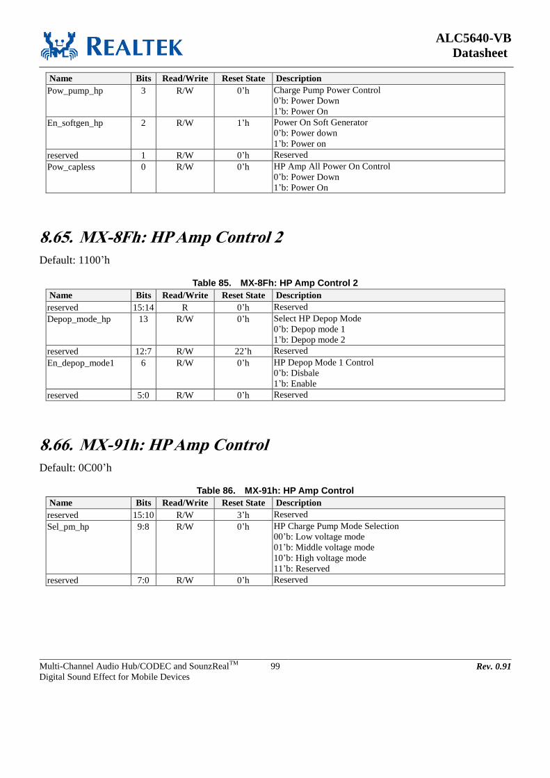
ALC5640-VB
Datasheet
Multi-Channel Audio Hub/CODEC and SounzRealTM
Digital Sound Effect for Mobile Devices
99 Rev. 0.91
Name Bits Read/Write Reset State Description
Pow_pump_hp 3 R/W 0’h Charge Pump Power Control
0’b: Power Down
1’b: Power On
En_softgen_hp 2 R/W 1’h Power On Soft Generator
0’b: Power down
1’b: Power on
reserved 1 R/W 0’h Reserved
Pow_capless 0 R/W 0’h HP Amp All Power On Control
0’b: Power Down
1’b: Power On
8.65. MX-8Fh: HP Amp Control 2
Default: 1100’h
Table 85. MX-8Fh: HP Amp Control 2
Name Bits Read/Write Reset State Description
reserved 15:14 R 0’h Reserved
Depop_mode_hp 13 R/W 0’h Select HP Depop Mode
0’b: Depop mode 1
1’b: Depop mode 2
reserved 12:7 R/W 22’h Reserved
En_depop_mode1 6 R/W 0’h HP Depop Mode 1 Control
0’b: Disbale
1’b: Enable
reserved 5:0 R/W 0’h Reserved
8.66. MX-91h: HP Amp Control
Default: 0C00’h
Table 86. MX-91h: HP Amp Control
Name Bits Read/Write Reset State Description
reserved 15:10 R/W 3’h Reserved
Sel_pm_hp 9:8 R/W 0’h HP Charge Pump Mode Selection
00’b: Low voltage mode
01’b: Middle voltage mode
10’b: High voltage mode
11’b: Reserved
reserved 7:0 R/W 0’h Reserved

ALC5640-VB
Datasheet
Multi-Channel Audio Hub/CODEC and SounzRealTM
Digital Sound Effect for Mobile Devices
100 Rev. 0.91
8.67. MX-92h: SPKVDD Detection Control
Default: 0000’h
Table 87. MX-92h: SPKVDD Detection Control
Name Bits Read/Write Reset State Description
en_spk_auto_ratio 15 R/W 0’h Enable SPKVDD Detection
0’b: Disable
1’b: Enable
en_spk_auto_gain 14 R/W 0’h Enable Speaker Amp Auto Ratio Gain Control
(Digital will mapping ratio gain table by SPKVDD
detection)
0’b: Disable
1’b: Enable
reserved 13:0 R 0’h Reserved
AC Ratio Gain would be:
Ratio Gain Table (ACVDD with SPKVDD)
ACVDD SPKVDD Voltage Detected Code AC+DC Ratio Gain FBGAIN[3:0]
1.8V
<3.0V 0000 1.94 0000
3.0V ~ 3.3V 0001 1.94 0000
3.3V ~ 3.5V 0010 2 0001
3.5V ~ 3.6V 0011 2.11 0010
3.6V ~ 3.8V 0100 2.22 0011
3.8V ~ 4.0V 0101 2.33 0100
4.0V ~ 4.2V 0110 2.44 0101
4.2V ~ 4.4V 0111 2.55 0110
4.4V ~ 4.6V 1000 2.66 0111
4.6V ~ 4.8V 1001 2.77 1000
4.8V ~ 5V 1010 3.00 1001
>5V 1011 3.30 1010
8.68. MX-93h: MICBIAS Control
Default: 3000’h
Table 88. MX-93h: MICBIAS Control
Name Bits Read/Write Reset State Description
Sel_micbias1 15 R/W 0’h MICBIAS1 Output Voltage Control
0’b: 0.9 * MICVDD
1’b: 0.75 * MICVDD
reserved 14:12 R/W 3’h Reserved
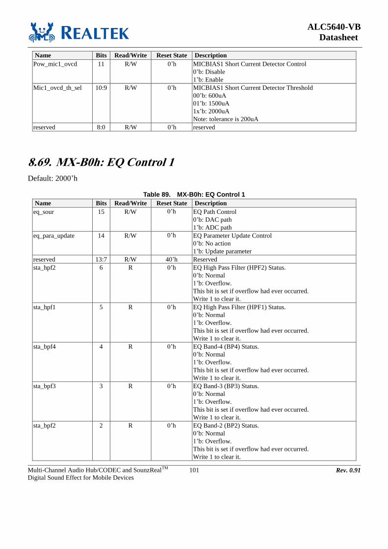
ALC5640-VB
Datasheet
Multi-Channel Audio Hub/CODEC and SounzRealTM
Digital Sound Effect for Mobile Devices
101 Rev. 0.91
Name Bits Read/Write Reset State Description
Pow_mic1_ovcd 11 R/W 0’h MICBIAS1 Short Current Detector Control
0’b: Disable
1’b: Enable
Mic1_ovcd_th_sel 10:9 R/W 0’h MICBIAS1 Short Current Detector Threshold
00’b: 600uA
01’b: 1500uA
1x’b: 2000uA
Note: tolerance is 200uA
reserved 8:0 R/W 0’h reserved
8.69. MX-B0h: EQ Control 1
Default: 2000’h
Table 89. MX-B0h: EQ Control 1
Name Bits Read/Write Reset State Description
eq_sour 15 R/W 0’h EQ Path Control
0’b: DAC path
1’b: ADC path
eq_para_update 14 R/W 0’h EQ Parameter Update Control
0’b: No action
1’b: Update parameter
reserved 13:7 R/W 40’h Reserved
sta_hpf2 6 R 0’h EQ High Pass Filter (HPF2) Status.
0’b: Normal
1’b: Overflow.
This bit is set if overflow had ever occurred.
Write 1 to clear it.
sta_hpf1 5 R 0’h EQ High Pass Filter (HPF1) Status.
0’b: Normal
1’b: Overflow.
This bit is set if overflow had ever occurred.
Write 1 to clear it.
sta_bpf4 4 R 0’h EQ Band-4 (BP4) Status.
0’b: Normal
1’b: Overflow.
This bit is set if overflow had ever occurred.
Write 1 to clear it.
sta_bpf3 3 R 0’h EQ Band-3 (BP3) Status.
0’b: Normal
1’b: Overflow.
This bit is set if overflow had ever occurred.
Write 1 to clear it.
sta_bpf2 2 R 0’h EQ Band-2 (BP2) Status.
0’b: Normal
1’b: Overflow.
This bit is set if overflow had ever occurred.
Write 1 to clear it.

ALC5640-VB
Datasheet
Multi-Channel Audio Hub/CODEC and SounzRealTM
Digital Sound Effect for Mobile Devices
102 Rev. 0.91
Name Bits Read/Write Reset State Description
sta_bpf1 1 R 0’h EQ Band-1 (BP1) Status.
0’b: Normal
1’b: Overflow.
This bit is set if overflow had ever occurred.
Write 1 to clear it.
sta_lpf 0 R 0’h EQ Low Pass Filter (LPF) Status.
0’b: Normal
1’b: Overflow.
This bit is set if overflow had ever occurred.
Write 1 to clear it.
8.70. MX-B1h: EQ Control 2
Default: 0000’h
Table 90. MX-B1h: EQ Control 2
Name Bits Read/Write Reset State Description
reserved 15:9 R 0’h Reserved
reg_typ_hpf_en 8 R/W 0’h EQ High Pass Filter1 Mode Control
0’b: High frequency shelving filter 1’b: 1
st order Butterworth HPF (-20dB per decade)
reg_typ_lpf_en 7 R/W 0’h EQ Low Pass Filter Mode Control
0’b: Low frequency shelving filter 1’b: 1
st order Butterworth LPF (-20dB per decade)
en_hpf2 6 R/W 0’h EQ High Pass 2nd
Butterworth Filter (HPF) Control.
0’b: Disabled (bypass) and reset
1’b: Enabled
en_hpf1 5 R/W 0’h EQ High Pass Filter (HPF) Control.
0’b: Disabled (bypass) and reset
1’b: Enabled
en_bpf4 4 R/W 0’h EQ Band-4 (BP4) shelving Filter Control.
0’b: Disabled and reset
1’b: Enabled.
en_bpf3 3 R/W 0’h EQ Band-3 (BP3) shelving Filter Control.
0’b: Disabled and reset
1’b: Enabled.
en_bpf2 2 R/W 0’h EQ Band-2 (BP2) shelving Filter Control.
0’b: Disabled and reset
1’b: Enabled.
en_bpf1 1 R/W 0’h EQ Band-1 (BP1) shelving Filter Control.
0’b: Disabled and reset
1’b: Enabled.
en_lpf 0 R/W 0’h EQ Low Pass Filter (LPF) Filter Control.
0’b: Disabled and reset
1’b: Enabled.

ALC5640-VB
Datasheet
Multi-Channel Audio Hub/CODEC and SounzRealTM
Digital Sound Effect for Mobile Devices
103 Rev. 0.91
8.71. MX-B4h: DRC/AGC Control 1
Default: 2206’h
Table 91. MX-B4h: DRC/AGC Control 1
Name Bits Read/Write Reset State Description
sel_drc_agc 15:14 R/W 0’h DRC/AGC Enable
00’b: Disable DRC/AGC
01’b: Enable DRC to DAC Path
10’b: Disable DRC/AGC
11’b: Enable AGC to ADC Path
update_drc_agc_para
m
13 R 1’h Update DRC/AGC Parameter
Write 1’b to update all DRC/AGC parameter
sel_drc_agc_atk 12:8 R/W 2’h Select DRC/AGC attack rate (0.375dB/TU)
00’h: 83 uSec
01’h: 0.167 mSec
…
10’h: 5.46 Sec
Others: Reserved
Drc_agc_rate_sel 7:5 R/W 0’h DRC/AGC Rate Control for Sample Rate Change
001’b: 48kHz
010’b: 96kHz
011’b: 192kHz
101’b: 44.1kHz
110’b: 88.2kHz
111’b: 176.4kHz
Others: Reserved
sel_rc_rate 4:0 R/W 6’h Select DRC/AGC recovery rate (0.375dB/TU)
00’h: 83 uSec
01’h: 0.167 mSec
…
10’h: 5.46 Sec
Others: Reserved
attack time=(4*2^n)/Sample_Rate, n = MX-B4[12:8], default=0.33mS
recovery time=(4*2^n)/Sample_Rate, n = MX-B4[4:0], default=5.3mS
When change I2S’s sample rate, the DRC/AGC rate control is need to be changed same with I2S’s sample rate. When
change the DRC/AGC rate, the parameter of DRC/AGC isn’t need be modified.
When I2S’s sample rate is below 48kHz, that need to set the DRC/AGC rate to 48kHz and re-calculate the DRC/AGC’s
parameter by I2S’s sample rate.
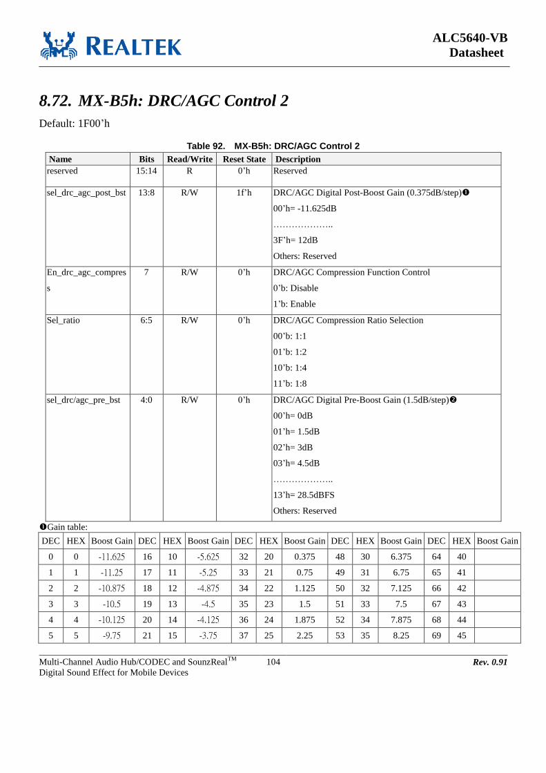
ALC5640-VB
Datasheet
Multi-Channel Audio Hub/CODEC and SounzRealTM
Digital Sound Effect for Mobile Devices
104 Rev. 0.91
8.72. MX-B5h: DRC/AGC Control 2
Default: 1F00’h
Table 92. MX-B5h: DRC/AGC Control 2
Name Bits Read/Write Reset State Description
reserved 15:14 R 0’h Reserved
sel_drc_agc_post_bst 13:8 R/W 1f’h DRC/AGC Digital Post-Boost Gain (0.375dB/step)
00’h= -11.625dB
………………..
3F’h= 12dB
Others: Reserved
En_drc_agc_compres
s
7 R/W 0’h DRC/AGC Compression Function Control
0’b: Disable
1’b: Enable
Sel_ratio 6:5 R/W 0’h DRC/AGC Compression Ratio Selection
00’b: 1:1
01’b: 1:2
10’b: 1:4
11’b: 1:8
sel_drc/agc_pre_bst 4:0 R/W 0’h DRC/AGC Digital Pre-Boost Gain (1.5dB/step)
00’h= 0dB
01’h= 1.5dB
02’h= 3dB
03’h= 4.5dB
………………..
13’h= 28.5dBFS
Others: Reserved
Gain table:
DEC HEX Boost Gain DEC HEX Boost Gain DEC HEX Boost Gain DEC HEX Boost Gain DEC HEX Boost Gain
0 0 -11.625 16 10 -5.625 32 20 0.375 48 30 6.375 64 40
1 1 -11.25 17 11 -5.25 33 21 0.75 49 31 6.75 65 41
2 2 -10.875 18 12 -4.875 34 22 1.125 50 32 7.125 66 42
3 3 -10.5 19 13 -4.5 35 23 1.5 51 33 7.5 67 43
4 4 -10.125 20 14 -4.125 36 24 1.875 52 34 7.875 68 44
5 5 -9.75 21 15 -3.75 37 25 2.25 53 35 8.25 69 45

ALC5640-VB
Datasheet
Multi-Channel Audio Hub/CODEC and SounzRealTM
Digital Sound Effect for Mobile Devices
105 Rev. 0.91
6 6 -9.375 22 16 -3.375 38 26 2.625 54 36 8.625 70 46
7 7 -9 23 17 -3 39 27 3 55 37 9 71 47
8 8 -8.625 24 18 -2.625 40 28 3.375 56 38 9.375 72 48
9 9 -8.25 25 19 -2.25 41 29 3.75 57 39 9.75 73 49
10 A -7.875 26 1A -1.875 42 2A 4.125 58 3A 10.125 74 4A
11 B -7.5 27 1B -1.5 43 2B 4.5 59 3B 10.5 75 4B
12 C -7.125 28 1C -1.125 44 2C 4.875 60 3C 10.875 76 4C
13 D -6.75 29 1D -0.75 45 2D 5.25 61 3D 11.25
14 E -6.375 30 1E -0.375 46 2E 5.625 62 3E 11.625
15 F -6 31 1F 0 47 2F 6 63 3F 12
DEC HEX Boost Gain DEC HEX Boost Gain
0 0 0 16 10 24
1 1 1.5 17 11 25.5
2 2 3 18 12 27
3 3 4.5 19 13 28.5
4 4 6 20 14
5 5 7.5 21 15
6 6 9 22 16
7 7 10.5 23 17
8 8 12 24 18
9 9 13.5 25 19
10 A 15 26 1A
11 B 16.5 27 1B
12 C 18 28 1C
13 D 19.5 29 1D
14 E 21 30 1E
15 F 22.5 31 1F

ALC5640-VB
Datasheet
Multi-Channel Audio Hub/CODEC and SounzRealTM
Digital Sound Effect for Mobile Devices
106 Rev. 0.91
8.73. MX-B6h: DRC/AGC Control 3
Default: 0000’h
Table 93. MX-B6h: DRC/AGC Control 3
Name Bits Read/Write Reset State Description
Noise_gate_boost 15:12 R/W 0’h Select Compensation Gain When Signal is Below Noise Gate
0’h: 0dB
1’h: 3dB
2’h: 6dB
…
E’h: 42dB
F’h: 45dB
sel_drc_agc_thmax 11:7 R/W 0’h DRC/AGC Limiter Level (1.5dB/step)
00’h= 0dBFS
01’h= -1.5dBFS
02’h= -3dBFS
03’h= -4.5dBFS
…
1F’h= -46.5dBFS
en_drc_agc_noise_ga
te
6 R/W 0’h Enable Noise Gate function
0’b: Diaable
1’b: Enable
En_drc_agc_noise_ga
te_hold
5 R/W 0’h Enable Noise Gate Hold Data Function
0’b: Disable
1’b: Enable
sel_drc_agc_noise_th 4:0 R/W 0’h Noise Gate Threshold (-1.5dB/step)
00’h: -36dBFS
01’h: -375dBFS
………………..
1F’h: -82.5 dBFS

ALC5640-VB
Datasheet
Multi-Channel Audio Hub/CODEC and SounzRealTM
Digital Sound Effect for Mobile Devices
107 Rev. 0.91
8.74. MX-BBh: Jack Detection Control 1
Default: 0000’h
Table 94. MX-BBh: Jack Detection Control 1
Name Bits Read/Write Reset State Description
sel_jd_source 15:13 R/W 0’h Jack Detect Selection
000’b: OFF
001’b: GPIO1
010’b: JD1 and enable IN1N pin share
011’b: JD2 and enable IN2N pin share
100’b: GPIO2
Others: Reserved
reserved 12 R 0’h Reserved
en_jd_hpo 11 R/W 0’h Enable Jack Detect Trigger HPOUT
0’b: Disable
1’b: Enable
polarity_jd_tri_hpo 10 R/W 0’h Select Jack Detect Polarity Trigger HPOUT
0’b: Low trigger
1’b: High trigger
en_jd_spo_l 9 R/W 0’h Enable Jack Detect Trigger SPK_OUT_LP/LN
0’b: Disable
1’b: Enable
polarity_jd_tri_spo_l 8 R/W 0’h Select Jack Detect Polarity Trigger SPO_LP/LN
0’b: Low trigger
1’b: High trigger
en_jd_spo_r 7 R/W 0’h Enable Jack Detect Trigger SPO_RP/RN
0’b: Disable
1’b: Enable
polarity_jd_tri_spo_r 6 R/W 0’h Select Jack Detect Polarity Trigger SPO_RP/RN
0’b: Low trigger
1’b: High trigger
en_jd_mono 5 R/W 0’h Enable Jack Detect Trigger MONOOUT
0’b: Disable
1’b: Enable
polarity_jd_tri_mono 4 R/W 0’h Select Jack Detect Polarity Trigger MONOOUT
0’b: Low trigger
1’b: High trigger
en_jd_lout 3 R/W 0’h Enable Jack Detect Trigger LOUT
0’b: Disable
1’b: Enable
polarity_jd_tri_lout 2 R/W 0’h Select Jack Detect Polarity Trigger LOUT
0’b: Low trigger
1’b: High trigger
reserved 1:0 R/W 0’h reserved

ALC5640-VB
Datasheet
Multi-Channel Audio Hub/CODEC and SounzRealTM
Digital Sound Effect for Mobile Devices
108 Rev. 0.91
8.75. MX-BCh: Jack Detection Control 2
Default: 0000’h
Table 95. MX-BCh: Jack Detection Control 2
Name Bits Read/Write Reset State Description
reserved 15:6 R 0’h Reserved
en_snc_det 5:4 R/W 0’h Select Detection Source for SNC On/Off Mode
00’b: Disable
01’b: From MICBIAS1 Over-Current (sta_micbias1_ovcd)
10’b: Reserved
11’b: From JD (sta_jd_internal)
polarity_snc_det 3 R/W 0’h Select SNC Detection Polarity Trigger for SNC On/Off
Mode
0’b: Low trigger
1’b: High trigger
En_sncmon_det 2:1 R/W 0’h Enable Detection Source for SNC Monitor Mode
00’b: Disable
01’b: From MICBIAS1 Over-Current (sta_micbias1_ovcd)
10’b: Reserved
11’b: From JD (sta_jd_internal)
polarity_sncmon_det 0 R/W 0’h Select SNCMON Detection Polarity Trigger for SNC
Monitor Mode
0: Low trigger
1: High trigger
8.76. MX-BDh: IRQ Control 1
Default: 0000’h
Table 96. MX-BDh: IRQ Control 1
Name Bits Read/Write Reset State Description
en_irq_jd 15 R/W 0’h IRQ Output Source Configure of Jack Detection Status
0’b: Disable
1’b: Enable
en_irq_ovtd 14 R/W 0’h IRQ Output Source Configure of Over Temperature Status
0’b: Disable
1’b: Enable
en_jd_sticky 13 R/W 0’h Sticky Control for Jack Detect
0’b: Disable
1’b: Enable
en_ovt_sticky 12 R/W 0’h Sticky Control for Over Temperature
0’b: Disable
1’b: Enable
inv_jd 11 R/W 0’h Jack Detection Status Polarity
0’b: Normal
1’b: Output Invert
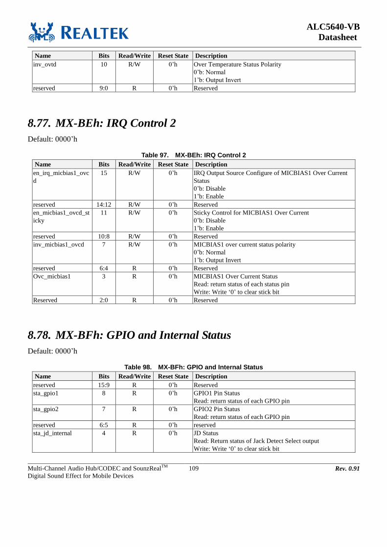
ALC5640-VB
Datasheet
Multi-Channel Audio Hub/CODEC and SounzRealTM
Digital Sound Effect for Mobile Devices
109 Rev. 0.91
Name Bits Read/Write Reset State Description
inv_ovtd 10 R/W 0’h Over Temperature Status Polarity
0’b: Normal
1’b: Output Invert
reserved 9:0 R 0’h Reserved
8.77. MX-BEh: IRQ Control 2
Default: 0000’h
Table 97. MX-BEh: IRQ Control 2
Name Bits Read/Write Reset State Description
en_irq_micbias1_ovc
d
15 R/W 0’h IRQ Output Source Configure of MICBIAS1 Over Current
Status
0’b: Disable
1’b: Enable
reserved 14:12 R/W 0’h Reserved
en_micbias1_ovcd_st
icky
11 R/W 0’h Sticky Control for MICBIAS1 Over Current
0’b: Disable
1’b: Enable
reserved 10:8 R/W 0’h Reserved
inv_micbias1_ovcd 7 R/W 0’h MICBIAS1 over current status polarity
0’b: Normal
1’b: Output Invert
reserved 6:4 R 0’h Reserved
Ovc_micbias1 3 R 0’h MICBIAS1 Over Current Status
Read: return status of each status pin
Write: Write ‘0’ to clear stick bit
Reserved 2:0 R 0’h Reserved
8.78. MX-BFh: GPIO and Internal Status
Default: 0000’h
Table 98. MX-BFh: GPIO and Internal Status
Name Bits Read/Write Reset State Description
reserved 15:9 R 0’h Reserved
sta_gpio1 8 R 0’h GPIO1 Pin Status
Read: return status of each GPIO pin
sta_gpio2 7 R 0’h GPIO2 Pin Status
Read: return status of each GPIO pin
reserved 6:5 R 0’h reserved
sta_jd_internal 4 R 0’h JD Status
Read: Return status of Jack Detect Select output
Write: Write ‘0’ to clear stick bit

ALC5640-VB
Datasheet
Multi-Channel Audio Hub/CODEC and SounzRealTM
Digital Sound Effect for Mobile Devices
110 Rev. 0.91
Name Bits Read/Write Reset State Description
ovt_status 3 R 0’h Over Temperature Status
Read: return status of each status pin
Write: Write ‘0’ to clear stick bit
reserved 2:1 R 0’h Reserved
sta_ovcd 0 R 0’h Speaker amplifier over current status
Read: return status of each status pin
8.79. MX-C0h: GPIO Control 1
Default: 0400’h
Table 99. MX-C0h: GPIO Control 1
Name Bits Read/Write Reset State Description
sel_gpio1_type 15 R/W 0’h GPIO1 Pin Function Select
0’b: GPIO1
1’b: IRQ output
sel_gpio2_type 14 R/W 0’h GPIO2 Pin Function Select
0’b: GPIO2
1’b: DMIC1_SCL
reserved 13:0 R/W 400’h Reserved
8.80. MX-C2h: GPIO Control 2
Default: 0000’h
Table 100. MX-C2h: GPIO Control 2
Name Bits Read/Write Reset State Description
reserved 15:6 R/W 0’h Reserved
sel_gpio2 5 R/W 0’h GPIO2 Pin Configuration
0’b: Input
1’b: Output
sel_gpio2_logic 4 R/W 0’h GPIO2 Output Pin Control
0’b: Drive Low
1’b: Drive High
inv_gpio2 3 R/W 0’h GPIO2 Pin Polarity
0’b: Normal
1’b: Output Invert
sel_gpio1 2 R/W 0’h GPIO1 Pin Configuration
0’b: Input
1’b: Output
sel_gpio1_logic 1 R/W 0’h GPIO1 Output Pin Control
0’b: Drive Low
1’b: Drive High
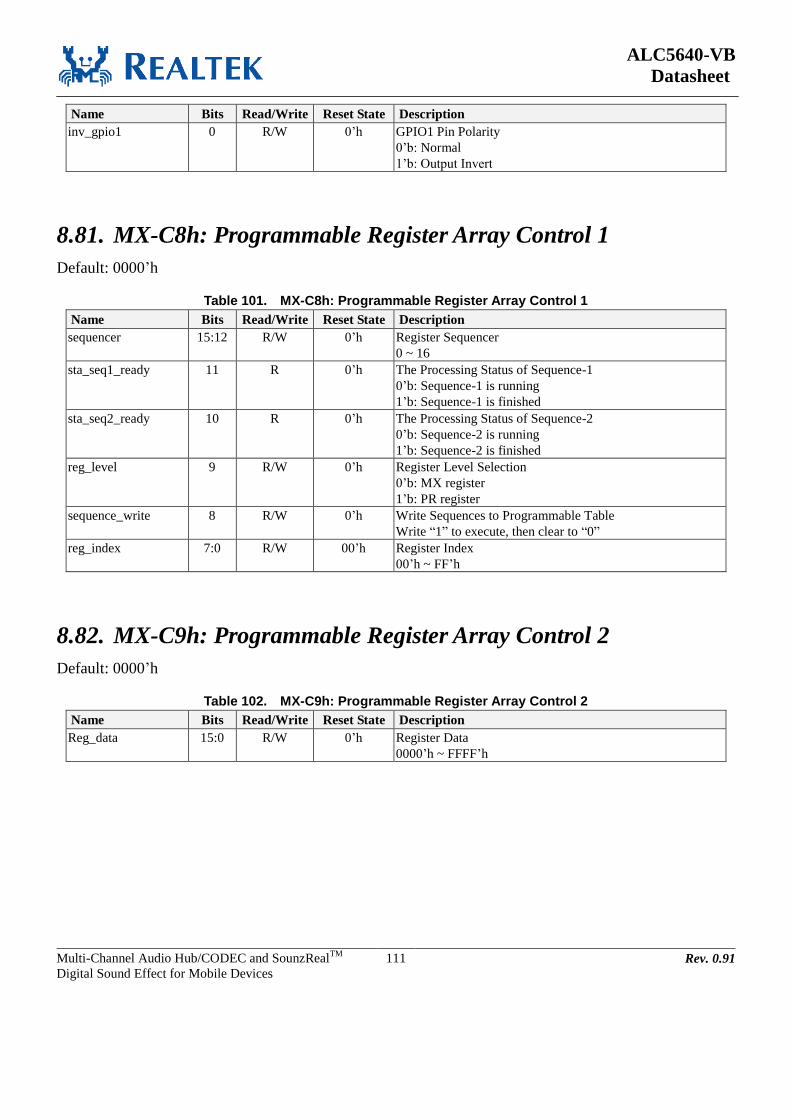
ALC5640-VB
Datasheet
Multi-Channel Audio Hub/CODEC and SounzRealTM
Digital Sound Effect for Mobile Devices
111 Rev. 0.91
Name Bits Read/Write Reset State Description
inv_gpio1 0 R/W 0’h GPIO1 Pin Polarity
0’b: Normal
1’b: Output Invert
8.81. MX-C8h: Programmable Register Array Control 1
Default: 0000’h
Table 101. MX-C8h: Programmable Register Array Control 1
Name Bits Read/Write Reset State Description
sequencer 15:12 R/W 0’h Register Sequencer
0 ~ 16
sta_seq1_ready 11 R 0’h The Processing Status of Sequence-1
0’b: Sequence-1 is running
1’b: Sequence-1 is finished
sta_seq2_ready 10 R 0’h The Processing Status of Sequence-2
0’b: Sequence-2 is running
1’b: Sequence-2 is finished
reg_level 9 R/W 0’h Register Level Selection
0’b: MX register
1’b: PR register
sequence_write 8 R/W 0’h Write Sequences to Programmable Table
Write “1” to execute, then clear to “0”
reg_index 7:0 R/W 00’h Register Index
00’h ~ FF’h
8.82. MX-C9h: Programmable Register Array Control 2
Default: 0000’h
Table 102. MX-C9h: Programmable Register Array Control 2
Name Bits Read/Write Reset State Description
Reg_data 15:0 R/W 0’h Register Data
0000’h ~ FFFF’h
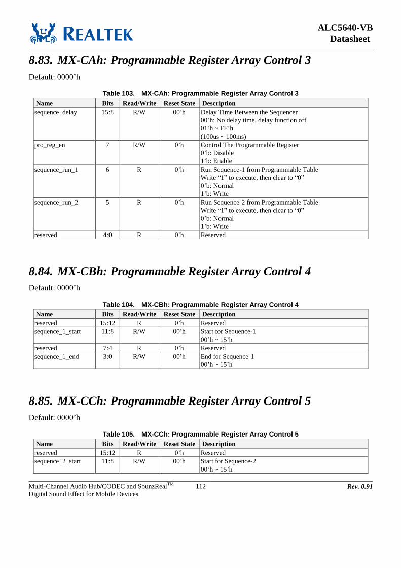
ALC5640-VB
Datasheet
Multi-Channel Audio Hub/CODEC and SounzRealTM
Digital Sound Effect for Mobile Devices
112 Rev. 0.91
8.83. MX-CAh: Programmable Register Array Control 3
Default: 0000’h
Table 103. MX-CAh: Programmable Register Array Control 3
Name Bits Read/Write Reset State Description
sequence_delay 15:8 R/W 00’h Delay Time Between the Sequencer
00’h: No delay time, delay function off
01’h ~ FF’h
(100us ~ 100ms)
pro_reg_en 7 R/W 0’h Control The Programmable Register 0’b: Disable 1’b: Enable
sequence_run_1 6 R 0’h Run Sequence-1 from Programmable Table
Write “1” to execute, then clear to “0”
0’b: Normal
1’b: Write
sequence_run_2 5 R 0’h Run Sequence-2 from Programmable Table
Write “1” to execute, then clear to “0”
0’b: Normal
1’b: Write
reserved 4:0 R 0’h Reserved
8.84. MX-CBh: Programmable Register Array Control 4
Default: 0000’h
Table 104. MX-CBh: Programmable Register Array Control 4
Name Bits Read/Write Reset State Description
reserved 15:12 R 0’h Reserved
sequence_1_start 11:8 R/W 00’h Start for Sequence-1
00’h ~ 15’h
reserved 7:4 R 0’h Reserved
sequence_1_end 3:0 R/W 00’h End for Sequence-1
00’h ~ 15’h
8.85. MX-CCh: Programmable Register Array Control 5
Default: 0000’h
Table 105. MX-CCh: Programmable Register Array Control 5
Name Bits Read/Write Reset State Description
reserved 15:12 R 0’h Reserved
sequence_2_start 11:8 R/W 00’h Start for Sequence-2
00’h ~ 15’h

ALC5640-VB
Datasheet
Multi-Channel Audio Hub/CODEC and SounzRealTM
Digital Sound Effect for Mobile Devices
113 Rev. 0.91
Name Bits Read/Write Reset State Description
reserved 7:4 R 0’h Reserved
sequence_2_end 3:0 R/W 00’h End for Sequence-2
00’h ~ 15’h
8.86. MX-CFh: SounzReal BassBack Control
Default: 0013’h
Table 106. MX-CFh: SounzReal BassBack Control
Name Bits Read/Write Reset State Description
En_bb 15 R/W 0’h Enable BassBack Function
0’b: Disable
1’b: Enable
Sel_bb_coef 14:12 R/W 0’h Select Control for BassBack Coefficient Type
000’b: Type A
001’b: Type B
010’b: Type C
011’b: Type D
1xx’b: Reserved
Reserved 11:6 R 0’h Reserved
Bb_boost_gain 5:0 R/W 13’h Select Control BassBack Boost Gain
000001’b: 1.5dB
000010’b: 3dB
………
010011’b: 24dB
………
011111’b: 42dB, with 1.5dB/Step
8.87. MX-D0h: SounzReal TruTreble Control 1
Default: 0680’h
Table 107. MX-D0h: SounzReal TruTreble Control 1
Name Bits Read/Write Reset State Description
reserved 15:14 R/W 0’h Reserved
En_mp 13 R/W 0’h Enable TruTreble Function
0’b: Disable
1’b: Enable
Mp_eg 12:8 R/W 6’h TruTreble Enhanced Gain Control
00000’b: -11.625dB
00001’b: -10.5dB
……….
00110’b: -3dB
...........
10100’b: 7.5dB
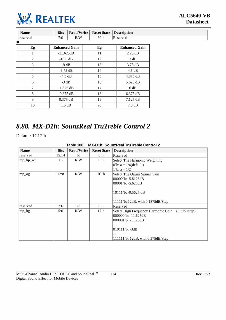
ALC5640-VB
Datasheet
Multi-Channel Audio Hub/CODEC and SounzRealTM
Digital Sound Effect for Mobile Devices
114 Rev. 0.91
Name Bits Read/Write Reset State Description
reserved 7:0 R/W 80’h Reserved
Eg Enhanced Gain Eg Enhanced Gain
1 -11.625dB 11 2.25 dB
2 -10.5 dB 12 3 dB
3 -9 dB 13 3.75 dB
4 -6.75 dB 14 4.5 dB
5 -4.5 dB 15 4.875 dB
6 -3 dB 16 5.625 dB
7 -1.875 dB 17 6 dB
8 -0.375 dB 18 6.375 dB
9 0.375 dB 19 7.125 dB
10 1.5 dB 20 7.5 dB
8.88. MX-D1h: SounzReal TruTreble Control 2
Default: 1C17’h
Table 108. MX-D1h: SounzReal TruTreble Control 2
Name Bits Read/Write Reset State Description
reserved 15:14 R 0’h Reserved
mp_hp_wt 13 R/W 0’h Select The Harmonic Weighting
0’b: a = 1/4(default)
1’b: a = 1/2
mp_og 12:8 R/W 1C’h Select The Origin Signal Gain
00000’b: -5.8125dB
00001’b: -5.625dB
…
10111’b: -0.5625 dB
...
11111’b: 12dB, with 0.1875dB/Step
reserved 7:6 R 0’h Reserved
mp_hg 5:0 R/W 17’h Select High Frequency Harmonic Gain (0.375 /step)
000000’b: -11.625dB
000001’b: -11.25dB
…
010111’b: -3dB
...
111111’b: 12dB, with 0.375dB/Step

ALC5640-VB
Datasheet
Multi-Channel Audio Hub/CODEC and SounzRealTM
Digital Sound Effect for Mobile Devices
115 Rev. 0.91
8.89. MX-D2h: SounzReal OmniHeadphone Control
Default: 8C00’h
Table 109. MX-D2h: SounzReal OmniHeadphone Control
Name Bits Read/Write Reset State Description
reserved 15 R/W 1’h Reserved
en_hp3d 14 R/W 0’h Enable OmniHeadphone
0’b: Disable
1’b: Enable
en_bt 13 R/W 0’h Enable OmniHeadphone True Bass
0’b: Disable
1’b: Enable
hp3d_lf_mixer_mode 12:11 R/W 1’h OmniHeadphone LF Mixer Mode Selection
00'b: Mode-1
01'b: Mode-2
10'b: Mode-3
10'b: Reserved
sel_hp3d_mode 10 R/W 1’h Select Control for OmniHeadphone Mode
0’b: Surround mode
1’b: Front mode
reserved 9:0 R/W 0’h Reserved
8.90. MX-D3h: Wind Filter Control – Enable/Disable
Default: AA20’h
Table 110. MX-D3h: Wind Filter Control – Enable/Disable
Name Bits Read/Write Reset State Description
adj_hpf_2nd_en 15 R/W 1’h Enable Adjustable 2nd
Wind Filter
0'b : Disable (bypass mode)
1'b : Enable
adj_hpf_coef_l_sel 14:12 R/W 2’h Left Channel Sample Rate Selection
000'b: 12k or 16k
001'b: 24k or 32k
010'b: 48k or 44.1k
011'b: 96k or 88.2k
100'b: 192k or 176.4k
narrow_hpf_en 11 R/W 1’h Enable 1st Narrow Band Wind Filter
0'b : Disable (bypass mode)
1'b :Enable
adj_hpf_coef_r_sel 10:8 R/W 2’h Right Channel Sample Rate Selection
000'b: 12k or 16k
001'b: 24k or 32k
010'b: 48k or 44.1k
011'b: 96k or 88.2k
100'b: 192k or 176.4k
reserved 7:0 R/W 20’h Reserved

ALC5640-VB
Datasheet
Multi-Channel Audio Hub/CODEC and SounzRealTM
Digital Sound Effect for Mobile Devices
116 Rev. 0.91
8.91. MX-D6h:HP Amp Control
Default: 0400’h
Table 111. MX-D6h: HP Amp Control
Name Bits Read/Write Reset State Description
reserved 15:6 R/W 10’h Reserved
Auto_pm_hp 5 R/W 0’h HP Charge Pump Voltage Auto Mode
0’b: Disable
1’b: Enable
reserved 4:0 R/W 0’h Reserved
8.92. MX-D9h: Soft Volume & ZCD Control
Default: 0809’h
Table 112. MX-D9h: Soft Volume & ZCD Control
Name Bits Read/Write Reset State Description
en_softvol 15 R/W 0’h Digital Soft Volume Delay Control
0’b: Disable
1’b: Enable
en_spo_svol 14 R/W 0’h SPOVOLL/R Soft Volume Delay Control
0’b: Disable
1’b: Enable
en_o_svol 13 R/W 0’h OUTVOLL/R Soft Volume Delay Control
0’b: Disable
1’b: Enable
en_hpo_svol 12 R/W 0’h HPOVOLL/R Soft Volume Delay Control
0’b: Disable
1’b: Enable
en_zcd_digital 11 R/W 1’h Digital Volume Zero Crossing Detection Control
0’b: Disable
1’b: Enable
pow_zcd 10 R/W 0’h Power On Zero Crossing
0’b: Power Down
1’b: Power On
En_zcd_recmixl 9 R/W 0’h RECMIXL Mute/Un-Mute ZCD Control
0’b: Disable
1’b: Enable
En_zcd_recmixr 8 R/W 0’h RECMIXR Mute/Un-Mute ZCD Control
0’b: Disable
1’b: Enable
En_zcd_spkmixl 7 R/W 0’h SPKMIXL Mute/Un-Mute ZCD Control
0’b: Disable
1’b: Enable
En_zcd_spkmixr 6 R/W 0’h SPKMIXR Mute/Un-Mute ZCD Control
0’b: Disable
1’b: Enable
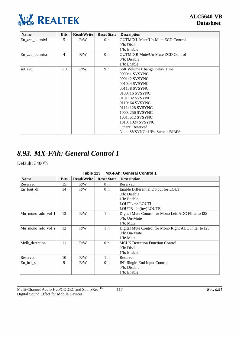
ALC5640-VB
Datasheet
Multi-Channel Audio Hub/CODEC and SounzRealTM
Digital Sound Effect for Mobile Devices
117 Rev. 0.91
Name Bits Read/Write Reset State Description
En_zcd_outmixl 5 R/W 0’h OUTMIXL Mute/Un-Mute ZCD Control
0’b: Disable
1’b: Enable
En_zcd_outmixr 4 R/W 0’h OUTMIXR Mute/Un-Mute ZCD Control
0’b: Disable
1’b: Enable
sel_svol 3:0 R/W 9’h Soft Volume Change Delay Time
0000: 1 SVSYNC
0001: 2 SVSYNC
0010: 4 SVSYNC
0011: 8 SVSYNC
0100: 16 SVSYNC
0101: 32 SVSYNC
0110: 64 SVSYNC
0111: 128 SVSYNC
1000: 256 SVSYNC
1001: 512 SVSYNC
1010: 1024 SVSYNC
Others: Reserved
Note: SVSYNC=1/Fs, Step:-1.5dBFS
8.93. MX-FAh: General Control 1
Default: 3400’h
Table 113. MX-FAh: General Control 1
Name Bits Read/Write Reset State Description
Reserved 15 R/W 0’h Reserved
En_lout_df 14 R/W 0’h Enable Differential Output for LOUT
0’b: Disable
1’b: Enable
LOUTL => LOUTL
LOUTR => (inv)LOUTR
Mu_mono_adc_vol_l 13 R/W 1’h Digital Mute Control for Mono Left ADC Filter to I2S
0’b: Un-Mute
1’b: Mute
Mu_mono_adc_vol_r 12 R/W 1’h Digital Mute Control for Mono Right ADC Filter to I2S
0’b: Un-Mute
1’b: Mute
Mclk_detection 11 R/W 0’h MCLK Detection Function Control
0’b: Disable
1’b: Enable
Reserved 10 R/W 1’h Reserved
En_in1_se 9 R/W 0’h IN1 Single-End Input Control
0’b: Disable
1’b: Enable
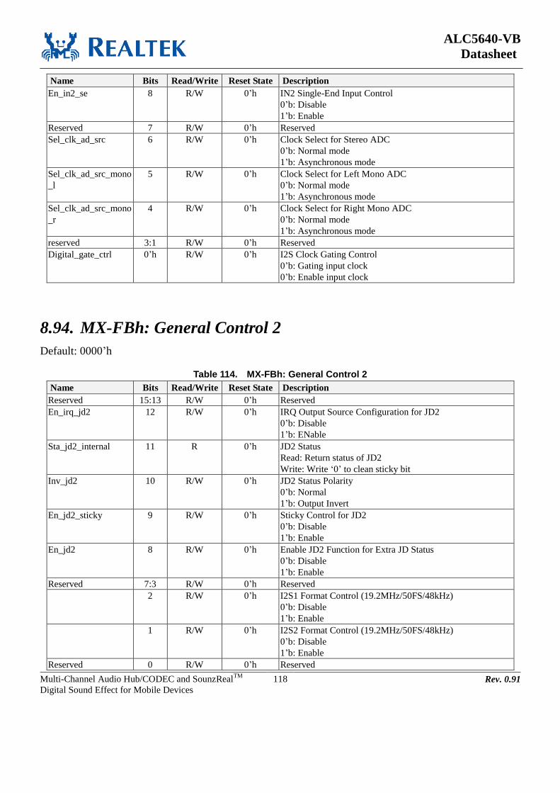
ALC5640-VB
Datasheet
Multi-Channel Audio Hub/CODEC and SounzRealTM
Digital Sound Effect for Mobile Devices
118 Rev. 0.91
Name Bits Read/Write Reset State Description
En_in2_se 8 R/W 0’h IN2 Single-End Input Control
0’b: Disable
1’b: Enable
Reserved 7 R/W 0’h Reserved
Sel_clk_ad_src 6 R/W 0’h Clock Select for Stereo ADC
0’b: Normal mode
1’b: Asynchronous mode
Sel_clk_ad_src_mono
_l
5 R/W 0’h Clock Select for Left Mono ADC
0’b: Normal mode
1’b: Asynchronous mode
Sel_clk_ad_src_mono
_r
4 R/W 0’h Clock Select for Right Mono ADC
0’b: Normal mode
1’b: Asynchronous mode
reserved 3:1 R/W 0’h Reserved
Digital_gate_ctrl 0’h R/W 0’h I2S Clock Gating Control
0’b: Gating input clock
0’b: Enable input clock
8.94. MX-FBh: General Control 2
Default: 0000’h
Table 114. MX-FBh: General Control 2
Name Bits Read/Write Reset State Description
Reserved 15:13 R/W 0’h Reserved
En_irq_jd2 12 R/W 0’h IRQ Output Source Configuration for JD2
0’b: Disable
1’b: ENable
Sta_jd2_internal 11 R 0’h JD2 Status
Read: Return status of JD2
Write: Write ‘0’ to clean sticky bit
Inv_jd2 10 R/W 0’h JD2 Status Polarity
0’b: Normal
1’b: Output Invert
En_jd2_sticky 9 R/W 0’h Sticky Control for JD2
0’b: Disable
1’b: Enable
En_jd2 8 R/W 0’h Enable JD2 Function for Extra JD Status
0’b: Disable
1’b: Enable
Reserved 7:3 R/W 0’h Reserved
2 R/W 0’h I2S1 Format Control (19.2MHz/50FS/48kHz)
0’b: Disable
1’b: Enable
1 R/W 0’h I2S2 Format Control (19.2MHz/50FS/48kHz)
0’b: Disable
1’b: Enable
Reserved 0 R/W 0’h Reserved

ALC5640-VB
Datasheet
Multi-Channel Audio Hub/CODEC and SounzRealTM
Digital Sound Effect for Mobile Devices
119 Rev. 0.91
8.95. PR-3Ah: Digital IO Driving Control
Default: 4002’h
Table 115. PR-3Ah: Digital IO Driving Control
Name Bits Read/Write Reset State Description
Sel_pad_drive 15:14 R/W 1’h Digital IO Driving Control
00’b: Setting-1 (Minimum driving)
01’b: Setting-2
10’b: Setting-3
11’b: Setting-4 (Maximum driving)
Reserved 13:0 R/W 2’h Reserved
8.96. PR-3Dh: ADC/DAC RESET Control
Default: 2400’h
Table 116. PR-3Dh: ADC/DAC RESET Control
Name Bits Read/Write Reset State Description
Reserved 15:13 R/W 1’h Reserved
En_ckgen_adc 12 R/W 0’h Enable ADC Clock Generator
0’b: Disable
1’b: Enable
Reserved 11:10 R/W 1’h Reserved
En_ckgen_dac 9 R/W 0’h Enable DAC Clock Generator
0’b: Disable
1’b: Enable
Reserved 8:0 R/W 0’h Reserved
8.97. PR-63h: SounzReal OmniSound Control
Default: 3737’h
Table 117. PR-63h: SounzReal OmniSound Control
Name Bits Read/Write Reset State Description
spk3d_en 15 R/W 0’h OmniSound Function Enable Control
0’b: Disable
1’b: Enable
spk3d_mix_mode 14:13 R/W 1’h OmniSound L/R Channel Mixing Mode
00’b: L+R,
01’b: L+0.5R,
10’b: L+0.25R,
11’b: L+0.125R

ALC5640-VB
Datasheet
Multi-Channel Audio Hub/CODEC and SounzRealTM
Digital Sound Effect for Mobile Devices
120 Rev. 0.91
Name Bits Read/Write Reset State Description
spk3d_center_gain 12:8 R/W 17’h OmniSound Center Part Gain Control
00’h: -23.25dB
…
17’h: -6dB
…
1f’h: 0dB, with 0.75dB/Step
reserved 7:5 R/W 1’h Reserved
spk3d_surr_gain 4:0 R/W 17’h OmniSound Surround Part Gain Control
00’h: -17.25dB
…
17’h: 0dB
…
1f’h: 6dB, with 0.75dB/Step
8.98. PR-6Ch: Wind Detector Control 1
Default: 1AC5’h
Table 118. PR-6Ch: Wind Detector Control 1
Name Bits Read/Write Reset State Description
en_wnr 15 R/W 0’h Enable Wind Noise Detection
0’b: Disable
1’b: Enable
reserved 14:0 R/W 1AC5’h Reserved
8.99. PR-6Dh: Wind Detector Control 2
Default: 00C0’h
Table 119. PR-6Dh: Wind Detector Control 2
Name Bits Read/Write Reset State Description
sel_wnr_fc_nowind 15:10 R/W 0’h Pre-Determined Fc When No Wind in Wind Noise Detector
0:30Hz, 1:60Hz, …, 2170Hz
sel_wnr_fc_breeze 9:4 R/W C’h Pre-Determined Fc When Weak Wind in Wind Noise
Detector
0:30Hz, 1:60Hz, …, 2170Hz
reserved 3:0 R/W 0’h Reserved

ALC5640-VB
Datasheet
Multi-Channel Audio Hub/CODEC and SounzRealTM
Digital Sound Effect for Mobile Devices
121 Rev. 0.91
8.100. PR-6Eh: Wind Detector Control 3
Default: 3019’h
Table 120. PR-6Eh: Wind Detector Control 3
Name Bits Read/Write Reset State Description
reserved 15:12 R/W 3’h Reserved
sel_hpf_fc 11:6 R/W 0’h Wind Filter Fc Selection
0:30Hz, 1:40Hz, …, 63:1030Hz
sel_wnr_fc_storm 5:0 R/W 19’h Pre-Determined Fc When Strong Wind in Wind Noise
Detector
0:30Hz, 1:60Hz, …, 2170Hz
8.101. PR-6Fh: Wind Detector Control 4
Default: 4096’h
Table 121. PR-6Fh: Wind Detector Control 4
Name Bits Read/Write Reset State Description
reserved 15:10 R/W 10’h Reserved
sel_wnr_ff_th_lo 9:0 R/W 96’h Threshold Setting Between No Wind and Weak Wind
8.102. PR-70h: Wind Detector Control 5
Default: C0BE’h
Table 122. PR-70h: Wind Detector Control 5
Name Bits Read/Write Reset State Description
reserved 15:10 R/W 18’h Reserved
sel_wnr_ff_th_hi 9:0 R/W BE’h Threshold Setting Between Weak Wind and Strong Wind
8.103. PR-73h: Wind Detector Control 6
Default: 0000’h
Table 123. PR-73h: Wind Detector Control 6
Name Bits Read/Write Reset State Description
reserved 15:14 R 0’h Reserved
fg_wnr_wind 13 R 0’h A Flag Indicate Wind Status
0’b: No Wind
1’b: Weak Wind
fg_wnr_strong 12 R 0’h A Flag Indicate Wind Status
0’b: Weak Wind
1’b: Strong Wind

ALC5640-VB
Datasheet
Multi-Channel Audio Hub/CODEC and SounzRealTM
Digital Sound Effect for Mobile Devices
122 Rev. 0.91
Name Bits Read/Write Reset State Description
reserved 11:0 R 0’h Reserved
8.104. PR-75h: SounzReal Dipole Speaker Control
Default: 5000’h
Table 124. PR-75h: SounzReal Dipole Speaker Control
Name Bits Read/Write Reset State Description
attenuate_ctrl 15:14 R/W 1’h Dipole Speaker Attenuate Control
00’b: 1.5dB
01’b: 3dB
10’b: 4.5dB
11’b: 6dB
reserved 13:11 R/W 2’h Reserved
dp_spk_en 10 R/W 0’h Enable Dipole Speaker
0’b: Disable
1’b: Enable
reserved 9:0 R 0’h Reserved
8.105. PR-A0h: EQ Low Pass Filter Coefficient (LPF:a1)
Default: 1C10’h
Table 125. PR-A0h: EQ Low Pass Filter Coefficient (LPF:a1)
Name Bits Read/Write Reset State Description
lpf_a1 15:0 R/W 1C10’h 2’s complement in 3.13 format. (The range is from –4~3.99,
the a1 should be in -2 ~ 1.99)
8.106. PR-A1h: EQ Low Pass Filter Gain (LPF:H0)
Default: 01F4’h
Table 126. PR-A1h: EQ Low Pass Filter Gain (LPF:H0)
Name Bits Read/Write Reset State Description
lpf_h0 15:0 R/W 01F4’h 2’s complement in 3.13 format. (The range is from –4~3.99,
the H0 should be in -4 ~ 3.99)
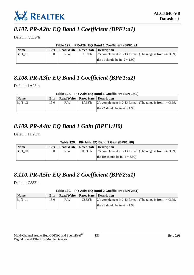
ALC5640-VB
Datasheet
Multi-Channel Audio Hub/CODEC and SounzRealTM
Digital Sound Effect for Mobile Devices
123 Rev. 0.91
8.107. PR-A2h: EQ Band 1 Coefficient (BPF1:a1)
Default: C5E9’h
Table 127. PR-A2h: EQ Band 1 Coefficient (BPF1:a1)
Name Bits Read/Write Reset State Description
Bpf1_a1 15:0 R/W C5E9’h 2’s complement in 3.13 format. (The range is from –4~3.99,
the a1 should be in -2 ~ 1.99)
8.108. PR-A3h: EQ Band 1 Coefficient (BPF1:a2)
Default: 1A98’h
Table 128. PR-A3h: EQ Band 1 Coefficient (BPF1:a2)
Name Bits Read/Write Reset State Description
Bpf1_a2 15:0 R/W 1A98’h 2’s complement in 3.13 format. (The range is from –4~3.99,
the a2 should be in -2 ~ 1.99)
8.109. PR-A4h: EQ Band 1 Gain (BPF1:H0)
Default: 1D2C’h
Table 129. PR-A4h: EQ Band 1 Gain (BPF1:H0)
Name Bits Read/Write Reset State Description
Bpf1_h0 15:0 R/W 1D2C’h 2’s complement in 3.13 format. (The range is from –4~3.99,
the H0 should be in -4 ~ 3.99)
8.110. PR-A5h: EQ Band 2 Coefficient (BPF2:a1)
Default: C882’h
Table 130. PR-A5h: EQ Band 2 Coefficient (BPF2:a1)
Name Bits Read/Write Reset State Description
Bpf2_a1 15:0 R/W C882’h 2’s complement in 3.13 format. (The range is from –4~3.99,
the a1 should be in -2 ~ 1.99)
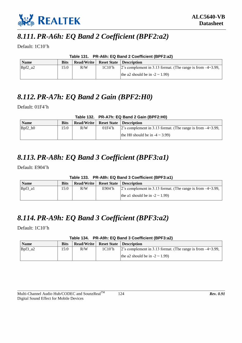
ALC5640-VB
Datasheet
Multi-Channel Audio Hub/CODEC and SounzRealTM
Digital Sound Effect for Mobile Devices
124 Rev. 0.91
8.111. PR-A6h: EQ Band 2 Coefficient (BPF2:a2)
Default: 1C10’h
Table 131. PR-A6h: EQ Band 2 Coefficient (BPF2:a2)
Name Bits Read/Write Reset State Description
Bpf2_a2 15:0 R/W 1C10’h 2’s complement in 3.13 format. (The range is from –4~3.99,
the a2 should be in -2 ~ 1.99)
8.112. PR-A7h: EQ Band 2 Gain (BPF2:H0)
Default: 01F4’h
Table 132. PR-A7h: EQ Band 2 Gain (BPF2:H0)
Name Bits Read/Write Reset State Description
Bpf2_h0 15:0 R/W 01F4’h 2’s complement in 3.13 format. (The range is from –4~3.99,
the H0 should be in -4 ~ 3.99)
8.113. PR-A8h: EQ Band 3 Coefficient (BPF3:a1)
Default: E904’h
Table 133. PR-A8h: EQ Band 3 Coefficient (BPF3:a1)
Name Bits Read/Write Reset State Description
Bpf3_a1 15:0 R/W E904’h 2’s complement in 3.13 format. (The range is from –4~3.99,
the a1 should be in -2 ~ 1.99)
8.114. PR-A9h: EQ Band 3 Coefficient (BPF3:a2)
Default: 1C10’h
Table 134. PR-A9h: EQ Band 3 Coefficient (BPF3:a2)
Name Bits Read/Write Reset State Description
Bpf3_a2 15:0 R/W 1C10’h 2’s complement in 3.13 format. (The range is from –4~3.99,
the a2 should be in -2 ~ 1.99)
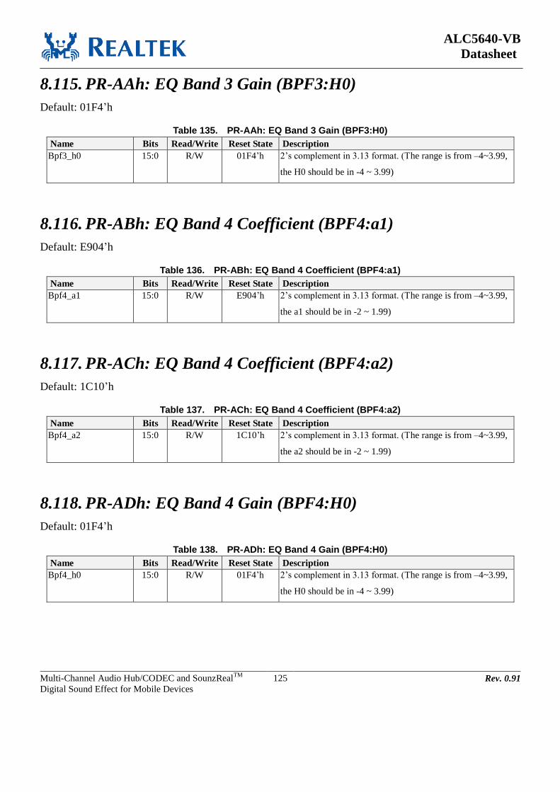
ALC5640-VB
Datasheet
Multi-Channel Audio Hub/CODEC and SounzRealTM
Digital Sound Effect for Mobile Devices
125 Rev. 0.91
8.115. PR-AAh: EQ Band 3 Gain (BPF3:H0)
Default: 01F4’h
Table 135. PR-AAh: EQ Band 3 Gain (BPF3:H0)
Name Bits Read/Write Reset State Description
Bpf3_h0 15:0 R/W 01F4’h 2’s complement in 3.13 format. (The range is from –4~3.99,
the H0 should be in -4 ~ 3.99)
8.116. PR-ABh: EQ Band 4 Coefficient (BPF4:a1)
Default: E904’h
Table 136. PR-ABh: EQ Band 4 Coefficient (BPF4:a1)
Name Bits Read/Write Reset State Description
Bpf4_a1 15:0 R/W E904’h 2’s complement in 3.13 format. (The range is from –4~3.99,
the a1 should be in -2 ~ 1.99)
8.117. PR-ACh: EQ Band 4 Coefficient (BPF4:a2)
Default: 1C10’h
Table 137. PR-ACh: EQ Band 4 Coefficient (BPF4:a2)
Name Bits Read/Write Reset State Description
Bpf4_a2 15:0 R/W 1C10’h 2’s complement in 3.13 format. (The range is from –4~3.99,
the a2 should be in -2 ~ 1.99)
8.118. PR-ADh: EQ Band 4 Gain (BPF4:H0)
Default: 01F4’h
Table 138. PR-ADh: EQ Band 4 Gain (BPF4:H0)
Name Bits Read/Write Reset State Description
Bpf4_h0 15:0 R/W 01F4’h 2’s complement in 3.13 format. (The range is from –4~3.99,
the H0 should be in -4 ~ 3.99)
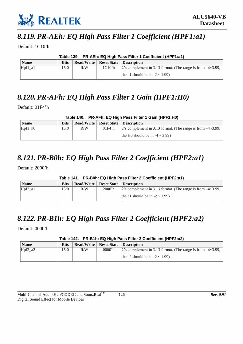
ALC5640-VB
Datasheet
Multi-Channel Audio Hub/CODEC and SounzRealTM
Digital Sound Effect for Mobile Devices
126 Rev. 0.91
8.119. PR-AEh: EQ High Pass Filter 1 Coefficient (HPF1:a1)
Default: 1C10’h
Table 139. PR-AEh: EQ High Pass Filter 1 Coefficient (HPF1:a1)
Name Bits Read/Write Reset State Description
Hpf1_a1 15:0 R/W 1C10’h 2’s complement in 3.13 format. (The range is from –4~3.99,
the a1 should be in -2 ~ 1.99)
8.120. PR-AFh: EQ High Pass Filter 1 Gain (HPF1:H0)
Default: 01F4’h
Table 140. PR-AFh: EQ High Pass Filter 1 Gain (HPF1:H0)
Name Bits Read/Write Reset State Description
Hpf1_h0 15:0 R/W 01F4’h 2’s complement in 3.13 format. (The range is from –4~3.99,
the H0 should be in -4 ~ 3.99)
8.121. PR-B0h: EQ High Pass Filter 2 Coefficient (HPF2:a1)
Default: 2000’h
Table 141. PR-B0h: EQ High Pass Filter 2 Coefficient (HPF2:a1)
Name Bits Read/Write Reset State Description
Hpf2_a1 15:0 R/W 2000’h 2’s complement in 3.13 format. (The range is from –4~3.99,
the a1 should be in -2 ~ 1.99)
8.122. PR-B1h: EQ High Pass Filter 2 Coefficient (HPF2:a2)
Default: 0000’h
Table 142. PR-B1h: EQ High Pass Filter 2 Coefficient (HPF2:a2)
Name Bits Read/Write Reset State Description
Hpf2_a2 15:0 R/W 0000’h 2’s complement in 3.13 format. (The range is from –4~3.99,
the a2 should be in -2 ~ 1.99)

ALC5640-VB
Datasheet
Multi-Channel Audio Hub/CODEC and SounzRealTM
Digital Sound Effect for Mobile Devices
127 Rev. 0.91
8.123. PR-B2h: EQ High Pass Filter 2 Gain (HPF2:H0)
Default: 2000’h
Table 143. PR-B2h: EQ High Pass Filter 2 Gain (HPF2:H0)
Name Bits Read/Write Reset State Description
Hpf2_h0 15:0 R/W 2000’h 2’s complement in 3.13 format. (The range is from –4~3.99,
the H0 should be in -4 ~ 3.99)
8.124. MX-FEh: Vendor ID
Default: 10EC’h
Table 144. MX-FEh: Vendor ID
Name Bits Read/Write Reset State Description
Vendor_id 15:0 R 10EC’h Vendor ID

ALC5640-VB
Datasheet
Multi-Channel Audio Hub/CODEC and SounzRealTM
Digital Sound Effect for Mobile Devices
128 Rev. 0.91
9. Electrical Characteristics
9.1. DC Characteristics
9.1.1. Absolute Maximum Ratings
Table 145. Absolute Maximum Ratings
Parameter Symbol Min Typ Max Units
Power Supplies
Digital IO Buffer
Digital Core
Analog
Analog
Headphone
Micbias
Speaker
DBVDD
DCVDD
AVDD
DACREF
CPVDD
MICVDD
SPKVDD
-0.3
-0.3
-0.3
-0.3
-0.3
-0.3
-0.3
-
-
-
-
-
-
-
3.63
1.98
1.98
1.98
1.98
3.63
71
V
V
V
V
V
V
V
Operating Ambient Temperature Ta -25 - +85 oC
Storage Temperature Ts -55 - +125 oC
Note 1: SPKVDD=5V with 3.5% duty cycle Power bouncing up to SPKVDD=8V is acceptable.
9.1.2. Recommended Operating Conditions
Table 146. Recommended Operating Conditions
Parameter Symbol Min Typ Max Units
Digital IO Buffer DBVDD 1.71 1.8 3.6 V
Digital Core DCVDD 1.1 1.2 1.9 V
Analog AVDD 1.71 1.8 1.9 V
Analog DACREF 1.71 1.8 1.9 V
Headphone CPVDD 1.71 1.8 1.9 V
Micbias MICVDD 3.0 3.3 3.6 V
Speaker SPKVDD1 3.0 3.6/5.0 5.5 V
Note 1: A 10µF Capacitor must be connected from SPKVDD to SPKGND, and should be placed as close as possible to
the SPKVDD pin.
9.1.3. Static Characteristics
Table 147. Static Characteristics
Parameter Symbol Min Typ Max Units
Input Voltage Range VIN -0.30 - DBVDD+0.30 V
Low Level Input Voltage VIL - - 0.35DBVDD V
High Level Input Voltage VIH 0.65DBVDD - - V
High Level Output Voltage VOH 0.9DBVDD - - V
Low Level Output Voltage VOL - - 0.1DBVDD V
Output Buffer High Drive Current - 0.6 1.8 4.3 mA
Output Buffer Low Drive Current - 0.7 2.1 4.8 mA
Input Buffer Pull-Up Resistor - 55 110 270 K
Input Buffer Pull-Down Resistor - 63 130 300 K
Note: DBVDD=1.8V, DCVDD=1.2V, Tambient=40C.

ALC5640-VB
Datasheet
Multi-Channel Audio Hub/CODEC and SounzRealTM
Digital Sound Effect for Mobile Devices
129 Rev. 0.91
9.2. Analog Performance Characteristics
Table 148. Analog Performance Characteristics
Parameter Min Typ Max Units
Full Scale Input Voltage
Line Inputs (Single-ended)
MIC Inputs (Single-ended )
MIC Inputs (Differential)
-
-
-
0.6
0.6
1.2
-
-
-
Vrms
Vrms
Vrms
Full Scale Output Voltage
Line Outputs (Single-ended)
Line Outputs (Differential)
Headphone Amplifiers Outputs (For 10KOhm Load)
Headphone Amplifiers Outputs (For 16Ohm Load)
Headphone Amplifiers Outputs (For 32Ohm Load)
Speaker Amplifiers Outputs
(SPKVDD=5.0V with 4 Load, 1% THD+N)
-
-
-
-
-
-
1.0
1.0
1.0
0.7
0.9
2.9
-
-
-
-
-
-
Vrms
Vrms
Vrms
Vrms
Vrms
Vrms
S/N Ratio
Stereo DAC Direct to HP_L/R with 16/32/10KOhm
Stereo DAC Direct to SPK_OUT with 8Ohm/5V (Differential)
Line_In to Stereo ADC with 0dB (Single-end)
MIC_In to Stereo ADC with 0dB (Differential or Single-end)
MIC_In to Stereo ADC with 20dB and MICBIAS (Differential or
Single-end)
MIC_In to Stereo ADC with 40dB and MICBIAS (Differential or
Single-end)
MIC_In to Stereo ADC with 50dB and MICBIAS (Differential or
Single-end)
-
-
100
95
94
94
89
78
68
102
95
95
dBA
dBA
dBA
dBA
dBA
dBA
dBA
Total Harmonic Distortion + Noise
DAC Direct to HP_L/R
Po = 20mW/CH (16Ohm)
Po = 20mW/CH (32Ohm)
DAC Direct to HP_L/R with 10KOhm
-3dBFS
DAC Direct to MONO_P/N with 16Ohm
Po = 50mW/CH
Po = 60mW/CH
DAC Direct to SPK_OUT (Differential)
Po=1.2W (5V/8Ohm)
Po=2.1W (5V/4Ohm)
Po=920mW (4.2V/8Ohm)
Po=650mW (3.6V/8Ohm)
-81
-81
-86
-70
-65
<1
<1
<1
<1
-83
-83
dB
dB
dB
dB
dB
%
%
%
%
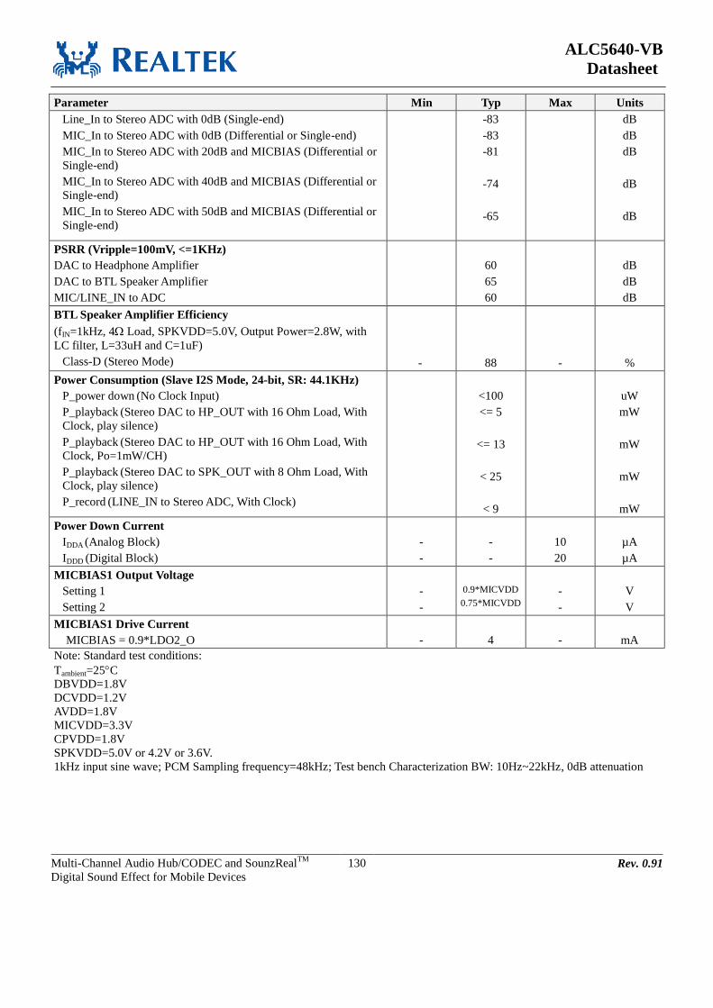
ALC5640-VB
Datasheet
Multi-Channel Audio Hub/CODEC and SounzRealTM
Digital Sound Effect for Mobile Devices
130 Rev. 0.91
Parameter Min Typ Max Units
Line_In to Stereo ADC with 0dB (Single-end)
MIC_In to Stereo ADC with 0dB (Differential or Single-end)
MIC_In to Stereo ADC with 20dB and MICBIAS (Differential or
Single-end)
MIC_In to Stereo ADC with 40dB and MICBIAS (Differential or
Single-end)
MIC_In to Stereo ADC with 50dB and MICBIAS (Differential or
Single-end)
-83
-83
-81
-74
-65
dB
dB
dB
dB
dB
PSRR (Vripple=100mV, <=1KHz)
DAC to Headphone Amplifier
DAC to BTL Speaker Amplifier
MIC/LINE_IN to ADC
60
65
60
dB
dB
dB
BTL Speaker Amplifier Efficiency
(fIN=1kHz, 4 Load, SPKVDD=5.0V, Output Power=2.8W, with
LC filter, L=33uH and C=1uF)
Class-D (Stereo Mode)
-
88
-
%
Power Consumption (Slave I2S Mode, 24-bit, SR: 44.1KHz)
P_power down (No Clock Input)
P_playback (Stereo DAC to HP_OUT with 16 Ohm Load, With
Clock, play silence)
P_playback (Stereo DAC to HP_OUT with 16 Ohm Load, With
Clock, Po=1mW/CH)
P_playback (Stereo DAC to SPK_OUT with 8 Ohm Load, With
Clock, play silence)
P_record (LINE_IN to Stereo ADC, With Clock)
<100
<= 5
<= 13
< 25
< 9
uW
mW
mW
mW
mW
Power Down Current
IDDA (Analog Block)
IDDD (Digital Block)
-
-
-
-
10
20
µA
µA
MICBIAS1 Output Voltage
Setting 1
Setting 2
-
-
0.9*MICVDD
0.75*MICVDD
-
-
V
V
MICBIAS1 Drive Current
MICBIAS = 0.9*LDO2_O
-
4
-
mA
Note: Standard test conditions:
Tambient=25C
DBVDD=1.8V
DCVDD=1.2V
AVDD=1.8V
MICVDD=3.3V
CPVDD=1.8V
SPKVDD=5.0V or 4.2V or 3.6V.
1kHz input sine wave; PCM Sampling frequency=48kHz; Test bench Characterization BW: 10Hz~22kHz, 0dB attenuation
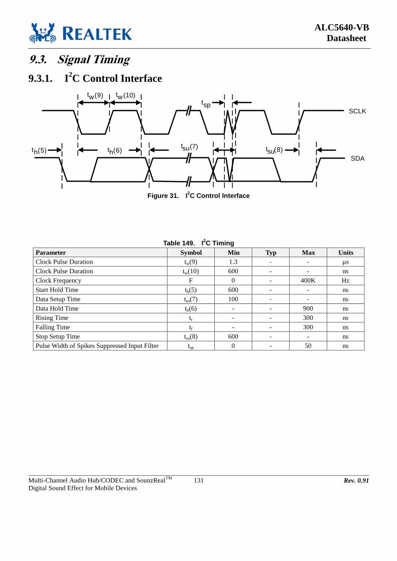
ALC5640-VB
Datasheet
Multi-Channel Audio Hub/CODEC and SounzRealTM
Digital Sound Effect for Mobile Devices
131 Rev. 0.91
9.3. Signal Timing
9.3.1. I2C Control Interface
th(5)
tw(9) tw(10)
th(6)tsu(7)
tsp
tsu(8)
SCLK
SDA
Figure 31. I2C Control Interface
Table 149. I2C Timing
Parameter Symbol Min Typ Max Units
Clock Pulse Duration tw(9) 1.3 - - µs
Clock Pulse Duration tw(10) 600 - - ns
Clock Frequency F 0 - 400K Hz
Start Hold Time th(5) 600 - - ns
Data Setup Time tsu(7) 100 - - ns
Data Hold Time th(6) - - 900 ns
Rising Time tr - - 300 ns
Falling Time tf - - 300 ns
Stop Setup Time tsu(8) 600 - - ns
Pulse Width of Spikes Suppressed Input Filter tsp 0 - 50 ns
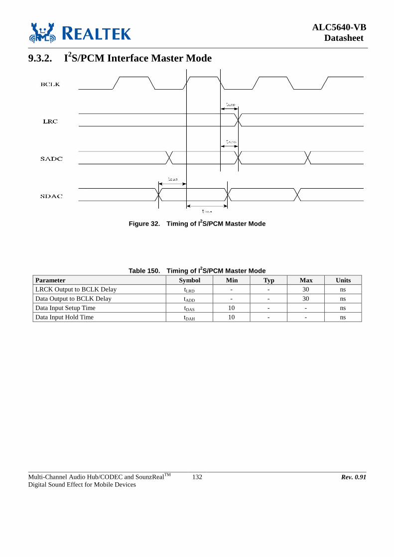
ALC5640-VB
Datasheet
Multi-Channel Audio Hub/CODEC and SounzRealTM
Digital Sound Effect for Mobile Devices
132 Rev. 0.91
9.3.2. I2S/PCM Interface Master Mode
Figure 32. Timing of I2S/PCM Master Mode
Table 150. Timing of I2S/PCM Master Mode
Parameter Symbol Min Typ Max Units
LRCK Output to BCLK Delay tLRD - - 30 ns
Data Output to BCLK Delay tADD - - 30 ns
Data Input Setup Time tDAS 10 - - ns
Data Input Hold Time tDAH 10 - - ns

ALC5640-VB
Datasheet
Multi-Channel Audio Hub/CODEC and SounzRealTM
Digital Sound Effect for Mobile Devices
133 Rev. 0.91
9.3.3. I2S/PCM Interface Slave Mode
Figure 33. I2S/PCM Slave Mode Timing
Table 151. I2S/PCM Slave Mode Timing
Parameter Symbol Min Typ Max Units
BCLK High Pulse Width tBCH 20 - - ns
BCLK Low Pulse Width tBCL 20 - - ns
LRCK Input Setup Time tLRS 30 - - ns
Data Output to BCLK Delay tADD - - 30 ns
Data Input Setup Time tDAS 10 - - ns
Data Input Hold Time tDAH 10 - - ns

ALC5640-VB
Datasheet
Multi-Channel Audio Hub/CODEC and SounzRealTM
Digital Sound Effect for Mobile Devices
134 Rev. 0.91
9.3.4. Digital Microphone Interface
TDAS TDAH
Left Data Right Data Left Data
Clock Output
Data Input
TCLKOUT
TDAS TDAH
Figure 34. Digital Microphone Interface Timing
Table 152. Digital Microphone Interface Timing
Parameter Symbol Min Typ Max Units
Clock Output Rate TCLKOUT 300 - - ns
Clock Duty Cycle 45:55 55:45
Data Input Setup Time TDAS 20 - - ns
Data Input Hold Time TDAH 10 - - ns
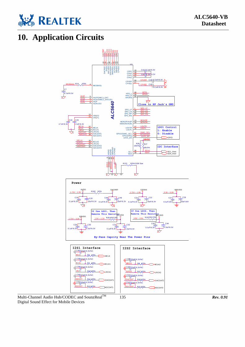
ALC5640-VB
Datasheet
Multi-Channel Audio Hub/CODEC and SounzRealTM
Digital Sound Effect for Mobile Devices
135 Rev. 0.91
10. Application Circuits
R13 0/5%
C12
2.2uF/6.3V
CPVEE
MONON
If Use LDO1, Then
Remove This Resistor
R14 0/5%
R26
10k/5%
GPIO1/IRQ
C28
10uF/16V
1.71V ~ 1.9V
LOUTL
SP
KG
ND
DG
ND
C21
0.1uF/6.3V
C22
10uF/6.3V
CPVDD
SPO_LN
C27
0.1uF/16V
SPKVDD
C29
0.1uF/6.3V
DBVDD
C31
0.1uF/6.3V
U1
AL
C5
64
0SPO_LP
1
LOUTL16LOUTR17
MICBIAS14
DA
CR
EF
10
SPO_LN48
SPO_RN47
SCL38
MONON/IN3N14
AV
DD
15
DACDAT133
ADCDAT134 GPIO2/DMIC_SCL
41
DC
VD
D42
DB
VD
D43
AG
ND
9
MONOP/IN3P13
IN1P/DMIC1_DAT5
DACDAT231
CPN121
CPVEE27
HPO_L28
BCLK136
LRCK135
CP
VD
D23
CPP120
VREF212
HPO_R26
SDA39
MCLK37
SPO_RP45
SP
KV
DD
L2
IN2N/JD28 IN2P7 IN1N/DMIC2_DAT/JD16
VREF111
SP
KG
ND
49
DG
ND
49
GPIO1/IRQ40
CP
GN
D22
ADCDAT232
BCLK230
LRCK229
SP
KV
DD
R46
HPOFB25
CPP219
CPN218
CPVPP24
MIC
VD
D3
LDO1_EN44
DB
VD
DC
PV
DD
SPO_LP
MONOP
SPO_RN
IN2N
BCLK
SPO_RP
I2C Interface
By-Pass Capcity Near The Power Pins
AVDD
3.0V ~ 3.6V R290/NC/5%
C19
0.1uF/6.3V
C20
10uF/6.3V
SDAT
IN1P
MCLK
C43
0.1uF/6.3V
C44
2.2uF/6.3V
MICVDD
R15 0/5%
GPIO
R17 0/5%
C41 2.2uF/6.3V
C52 22pF/6.3V/NC
R8 0/5%
VLRCKLRCK2
BCLK2VBCLK
I2S2 Interface
C39 22pF/6.3V/NC
SP
KV
DD
DC
VD
D
C40 22pF/6.3V/NC
DACDAT2
ADCDAT2
VDACDAT R18 0/5%
C54 22pF/6.3V/NC
C42 2.2uF/6.3V
VADCDAT
SP
KV
DD
MICBIAS1
3.3V ~ 5.0V
IN1N
AG
ND
HPOL
C18
4.7uF/6.3V
IN2P
DACDAT
C30
2.2uF/6.3V
C32
2.2uF/6.3V
HPOR
LDO1 Control
1: Enable
0: Disable
R10 0/5%
LRCK
R121 0/5%/1206 Size
ADCDAT
R102 0/5%
VADCDAT
DBVDD
VDACDAT
C25
2.2uF/6.3V
1.71V ~ 3.3V
C50 22pF/6.3V/NC
If Use LDO2, Then
Remove This Resistor
DA
CR
EF
VLRCK
Close to HP Jack's GND
R7 0/5%
LRCKLRCK1
BCLK1BCLK
I2S1 Interface
VBCLK
MCLK
C33 22pF/6.3V/NC
AV
DD
C34 22pF/6.3V/NC
CP
GN
D
R27
10k/5%
Power
1.0V ~ 1.2V
ADCDAT1
R28 0/NC/5%
DACDAT
SCLK
DACREF
C48
0.1uF/6.3V
C49
10uF/6.3V
DACDAT1
C10 2.2uF/6.3V
LDO1_EN
DBVDD
DCVDD
MIC
VD
D
R11 0/5%
R9 0/5%MCLK
C45 22pF/6.3V/NC
C7
4.7uF/6.3V
LOUTR
C51 22pF/6.3V/NC
1.71V ~ 1.9V
SCL_Host
CPVPP
DMIC_SCL
ADCDAT
SDA_Host

ALC5640-VB
Datasheet
Multi-Channel Audio Hub/CODEC and SounzRealTM
Digital Sound Effect for Mobile Devices
136 Rev. 0.91
DBVDD=1.8V
DMIC_SCL DMIC_SCL
DBVDD=1.8VIN1N
MIC9
CON2
CDP
G
DMIC2 Input
IN1N
DMIC1 Input
MIC10
CON2
CDP
G
Digital Microphone Input - Option 2 (IN1N)
N
P
N
P
Analog Audio Input_R
N
P
Analog Audio Input_L
N
P
MICBIAS1
DBVDD=1.8V
P
N
MICBIAS1
C69
100pF/6.3V
C91uF/6.3V
MONOP
C141uF/6.3V
MONON
R19
2.2k/5%MIC3 In
R22
2.2k/5%
MIC5
21
Ear Speaker
12
MONOP
MONON
Receiver Amp Out
C111uF/6.3V
IN2P
C13 1uF/6.3V
C15 1uF/6.3V
MIC2 In
IN2P
IN2N
R12
2.2k/5%
IN1PC231uF/6.3V
Line Input
R16
2.2k/5%
MIC1 In
MIC3
21
MIC4
21
DMIC_SCL
R30 0/5%
N
P
C161uF/6.3V
MONOP
Loud SPKL
12
MIC3 In
R23
2.2k/5%
R31 0/5%
MIC6
21
Loud SPKR
12
MICBIAS1MICBIAS1
SPO_LN
SPO_LP
SPO_RN
SPO_RP
C35
680pF/16V
C36
680pF/16V
C37
680pF/16V
C38
680pF/16V
Note: FB5~FB8 C35~C38 are reserved for EMI depression
C67
100pF/6.3V
C51uF/6.3V
C61uF/6.3V
IN2P
IN2N
R5
2.2k/5%MIC2 In
R4
2.2k/5%
C41uF/6.3V
IN1P
C81uF/6.3V
IN1N
R6
2.2k/5%
MICBIAS1
R3
2.2k/5%
MIC1 In
MIC2
21
MIC1
21
C68
100pF/6.3V
MICBIAS1
R122 0/5%/1206 Size DBVDD=1.8V
DMIC_SCLIN1P
MIC8
CON2
CDP
GR123 0/5%/1206 Size
DMIC2 Input
IN1P
DMIC1 Input
R124 0/5%/1206 Size
Analog Microphone Input - Option 2 (Single-End Mode)
Analog Microphone Input - Option 1 (Differential Mode)
LOUTR C24 1uF/6.3V
C26 1uF/6.3V
Line Out
J38
CON2
12
Heaphone Out
R20 33/5%
R21 33/5%
MIC7
CON2
CDP
G
HPOR PH2
HP Out
12345
HPOL
R101 22/5%LOUTL
R100 22/5%
R125 0/5%/1206 Size
Speaker - Stereo BTL Output
Digital Microphone Input - Option 1 (IN1P)
Figure 35. Application Circuit

ALC5640-VB
Datasheet
Multi-Channel Audio Hub/CODEC and SounzRealTM
Digital Sound Effect for Mobile Devices
137 Rev. 0.91
11. Package Information
11.1. Mechanical Dimensions Plastic Quad Flat No-Lead Package 48 Leads 6x6mm
2 Outline
Symbol Dimension in mm Dimension in inch
Min Nom Max Min Nom Max
A 0.75 0.85 1.00 0.030 0.034 0.039
A1 0.00 0.02 0.05 0.000 0.001 0.002
A3 0.20 REF 0.008 REF
b 0.15 0.20 0.25 0.006 0.008 0.010
D/E 6.00BSC 0.236BSC
D2/E2 4.15 4.4 4.65 0.163 0.173 0.183
e 0.40BSC 0.016BSC
L 0.30 0.40 0.50 0.012 0.016 0.020
Notes :
1. CONTROLLING DIMENSION :MILLIMETER(mm).
2. REFERENCE DOCUMENTL : JEDEC MO-220.
Figure 36. Package Dimension

ALC5640-VB
Datasheet
Multi-Channel Audio Hub/CODEC and SounzRealTM
Digital Sound Effect for Mobile Devices
138 Rev. 0.91
11.2. Package Thermal Information
Table 153. Thermal Information
Parameter Symbol Min Typ Max Units
QFN48 (6x6) Thermal Impedance
(Junction to Case) jc - 8.4 -
oC/W
QFN48 (6x6) Thermal Impedance
(Junction to Ambient) ja - 28 -
oC/W
*Follow JEDEC PCB:
1. PCB Dimension (L x W): 114.3mm x 101.6mm
2. PCB Thickness: 1.6mm
3. Number of Cu Layer-PCB: 4-layers (2S2P)
4. PCB Via Number: 10
5. Air flow: 0 (m/s)
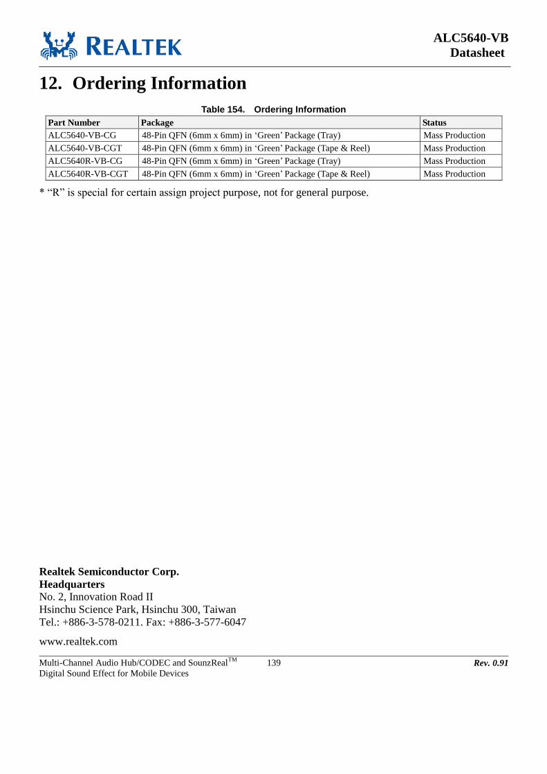
ALC5640-VB
Datasheet
Multi-Channel Audio Hub/CODEC and SounzRealTM
Digital Sound Effect for Mobile Devices
139 Rev. 0.91
12. Ordering Information
Table 154. Ordering Information
Part Number Package Status
ALC5640-VB-CG 48-Pin QFN (6mm x 6mm) in ‘Green’ Package (Tray) Mass Production
ALC5640-VB-CGT 48-Pin QFN (6mm x 6mm) in ‘Green’ Package (Tape & Reel) Mass Production
ALC5640R-VB-CG 48-Pin QFN (6mm x 6mm) in ‘Green’ Package (Tray) Mass Production
ALC5640R-VB-CGT 48-Pin QFN (6mm x 6mm) in ‘Green’ Package (Tape & Reel) Mass Production
* “R” is special for certain assign project purpose, not for general purpose.
Realtek Semiconductor Corp.
Headquarters
No. 2, Innovation Road II
Hsinchu Science Park, Hsinchu 300, Taiwan
Tel.: +886-3-578-0211. Fax: +886-3-577-6047
www.realtek.com


![Audio Hub CODEC with Master Hi-Fi DSPw WM5102S Audio Hub CODEC with Master Hi-Fi DSP WOLFSON MICROELECTRONICS plc Product Preview, April 2014, Rev 1.1 [1] This product is protected](https://img.dokumen.tips/doc/110x75/5e858796f50cec40e50051dd/audio-hub-codec-with-master-hi-fi-dsp-w-wm5102s-audio-hub-codec-with-master-hi-fi.jpg)