Embed Size (px)
Citation preview
MULE: Multi-Layer Virtual Network EmbeddingShihabur Rahman Chowdhury∗, Sara Ayoubi∗, Reaz Ahmed∗, Nashid Shahriar∗, Raouf Boutaba∗,
Jeebak Mitra†, and Liu Liu‡∗David R. Cheriton School of Computer Science, University of Waterloo
{sr2chowdhury | sayoubi | r5ahmed | nshahria | rboutaba}@uwaterloo.ca†Huawei Technologies Canada Research Center
[email protected]‡Huawei Technologies
Abstract—Network Virtualization (NV), considered as a keyenabler for overcoming the ossification of the Internet allowsmultiple heterogeneous virtual networks to co-exist over thesame substrate network. Resource allocation problems in NVhave been extensively studied for single layer substrates suchas IP or Optical networks. However, little effort has been putto address the same problem for multi-layer IP-over-Opticalnetworks. The increasing popularity of multi-layer networks fordeploying backbones combined with their unique characteristics(e.g., topological flexibility of the IP layer) calls for the need tocarefully investigate the resource provisioning problems arisingfrom their virtualization. In this paper, we address the problemof MUlti-Layer virtual network Embedding (MULE) on IP-over-Optical networks. We propose two solutions to MULE: an IntegerLinear Program (ILP) formulation for the optimal solution and aheuristic to address the computational complexity of the optimalsolution. We demonstrate through extensive simulations that onaverage our heuristic performs within ≈1.47× of optimal solutionand incurs ≈66% less cost than the state-of-the-art heuristic.
I. INTRODUCTION
Multi-layer IP-over-Optical networks are becoming a popu-lar choice among Infrastructure Providers (InPs) for deployingwide area networks [1]. Such multi-layer network typicallyconsists of an optical substrate for the physical communicationwith an IP overlay on top [2]. This network model is beingincreasingly adopted for backbone networks as it offers thebest of both worlds, i.e., the flexibility in addressing, resourceallocation, and traffic engineering of IP networks along withthe high capacity provided by optical networks. Despite theirincreasing popularity, research on addressing resource pro-visioning challenges for virtualizing such networks is stillin its infancy. A classical resource provisioning problem innetwork virtualization is Virtual Network Embedding (VNE),which consists in establishing a Virtual Network (VN) on aSubstrate Network (SN) with objectives such as minimizingresource provisioning cost [3], [4], maximizing the numberof admitted VNs [5], etc. VNE has been extensively studiedfor single-layer SNs [6] with significantly lesser attentionpaid to the multi-layer network substrates [7]. The topologicalflexibility provided by multi-layer networks [8] poses someunique challenges for VNE and calls for new investigations.
Similar to multi-layer networks, Mule, a hybrid species brings the best oftwo species together.
Several deployment models exist for multi-layer IP-over-Optical networks [9] including but not limited to: (i) IP overDense Wavelength Division Multiplexed (DWDM); (ii) IPover Optical Transport Network (OTN) over DWDM. DWDMnetworks have specific constraints such as wavelength conti-nuity for optical circuits and typically do not have transparenttraffic grooming capabilities. A more favorable choice (alsoour choice of technology) is to deploy an OTN [10] overa DWDM network with advanced transport capabilities (e.g.,traffic grooming without optical-electrical-optical conversion).The OTN in turn can be static, i.e., necessary interfaces onOTN nodes have been configured and the corresponding lightpaths in the DWDM layer have been lit to provision fixedbandwidth between OTN nodes. Or, the OTN can be dynamic,i.e., more bandwidth between OTN nodes can be provisionedby lighting new light paths in the DWDM. Clearly, theVNE problem for each of these scenarios requires dedicatedexplorations due to their unique constraints. As a first steptowards addressing VNE for multi-layer networks, we limit thescope of this paper to the case of a static OTN and leave theother possible deployment scenarios for future investigation.
Solving the VNE problem for multi-layer networks exhibitsmany unique challenges due to the topological flexibilityoffered by such networks. Concretely, although the OTN isfixed, the IP network is dynamic, i.e., new IP links can beestablished when needed by provisioning necessary capacityfrom the OTN. Such flexibility can be exploited if residualresources in the IP layer are insufficient to admit a new VN,or to reduce the cost of VN embedding by creating new IPlinks that reduce network diameter. Provisioning new IP linksin optical networks has been a tedious and manual task with along turnaround time. However, with the advances in opticalnetworking technologies [11] and centralized optical controlplane [12]–[15], such provisioning tasks are more and moreautomated. Even then, one should not abuse such capabilityto sporadically establish new IP links since it remains moreexpensive than embedding virtual links on existing IP links.In this regard, we are faced with the following challenges: (i)strike a balance between obtaining a low cost VN embeddingwhile minimizing the establishment of new IP links; (ii)simultaneously decide on whether to create an IP link or notand its embedding in the OTN.
978-3-901882-98-2 c© 2017 IFIP
In this paper, we study the problem of MUlti-Layer VirtualNetwork Embedding (MULE) focusing on IP-over-OTN sub-strate networks with the objective of minimizing total resourceprovisioning cost for embedding the VN while consideringthe possibility of establishing new IP links when necessary.Specifically, the contributions of this paper are as follows:• OPT-MULE: An Integer Linear Program (ILP) formula-
tion to find the optimal solution to MULE. The state-of-the-art in multi-layer VNE [7] does not optimally solvethe problem. To the best of our knowledge, this is thefirst optimal solution to MULE.
• FAST-MULE: A heuristic to tackle the computationalcomplexity of OPT-MULE. We also prove that ourheuristic solves the problem optimally for a specific classof VNs, i.e., star-shaped VNs. Further, we evaluate ourheuristic and compare it against the optimal solution andwith the state-of-the-art solution in the literature [7].
The rest of the paper is organized as follows. We begin witha discussion of related works in Section II. Then we introduceour model and formally define the problem in Section III. InSection IV, we present OPT-MULE, an ILP formulation tooptimally solve MULE, followed by our proposed heuristic,FAST-MULE in Section V. Our evaluation of the proposedsolutions are presented in Section VI. Finally, we concludewith some future research directions in Section VII.
II. RELATED WORKS
VNE is a well studied problem in network virtualizationand a significant body of research has solved a numberof its variants [4], [16]–[24]. However, it has been mostlystudied for single layer SNs, i.e., for IP, Optical or Wirelessnetworks. Despite the existence of a significant number ofproposals [25]–[27], VNE solutions for IP networks commonlyinvolve allocating compute and bandwidth resources for thevirtual nodes and links, respectively. In the case of opticalnetworks, solving VNE involves allocating compute resourcesand wavelength for virtual nodes and links, respectively [28].Optical networks have technological constraints such as dis-crete wavelength allocation, wavelength continuity etc. thatadd additional challenges to the VNE problem [29]. The state-of-the-art in optical network virtualization has mostly focusedon single layer optical networks.
More recently, Zhang et al., proposed a heuristic for solv-ing the multi-layer VNE problem for IP-over-DWDM net-works [7]. They also consider the possibility of modifying IPlayer topology by allocating wavelengths from the underlyingDWDM network. Zhang et al., proposed a two step embeddingprocess that first embeds the virtual nodes then the virtuallinks, which limits the solution space and hence the optimalityof the embedding. In contrast, we propose an ILP formulationfor optimally solving the multi-layer VNE problem. Also,our heuristic does not embed the virtual nodes and linksindependently from each other, rather jointly embeds them.
An orthogonal but somehow related area of research inmulti-layer network optimization focused on the issue ofcapacity planning in multi-layer networks [29], [30]. During
the initial capacity planning a traffic matrix for the IP layeris given and sufficient capacity needs to be allocated in bothIP and Optical layers to support that traffic matrix. Differentvariants of the problem exist that take different technologicalconstraints, deployment models, and failure scenarios intoaccount [31]–[38]. In contrast, the endpoint of the demands,i.e., virtual node placement, is not known in advance in multi-layer VNE, making this one a fundamentally different problemfrom multi-layer capacity planning. Having said that thesubstantial body of research in multi-layer capacity planninghas demonstrated clear advantages of resource allocation whenthe layers are jointly optimized as opposed to considering themin isolation [31], [39]. Our solution approach also takes a jointoptimization approach to the multi-layer VNE problem.
III. MULE: MULTI-LAYER VIRTUAL NETWORKEMBEDDING PROBLEM
We first present a mathematical representation of the inputs,i.e., the IP topology, the OTN topology, and the VN request.Then we formally define MULE.
A
B C
D E
Optical Transport Network
IP Network
15
10
10
10
15
985 990
990990
1000
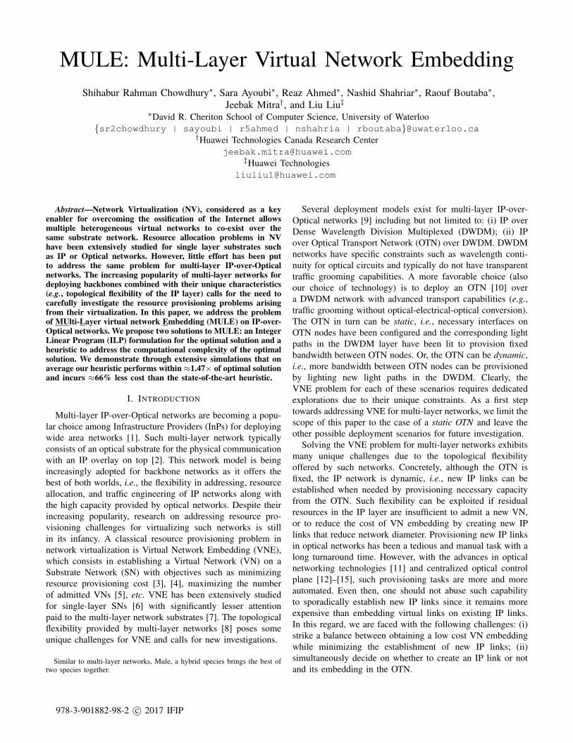
Fig. 1. Multi-Layer Infrastructure
A. Substrate Optical Transport Network (OTN)
We represent the substrate OTN as an undirected graph G =(V , E), where V and E are the set of Optical Cross Connects(OXCs) (referred as OTN nodes in the remaining) and OTNlinks, respectively (similar to [33]. Neighbors of an OTN nodeu ∈ V are represented with N (u). We assume the OTN to befixed, i.e., light paths atop a DWDM layer have been alreadylit to provision OTN links (u, v) ∈ E with bandwidth capacitybuv . This pre-provisioned bandwidth can be used to establishIP links between IP routers. The cost of allocating one unitof bandwidth from an OTN link (u, v) ∈ E is Cuv . Fig. 1illustrates an example of an OTN network, where the numberson each link represent its residual capacity.
B. Substrate IP Network
The substrate IP network is an undirected graph G′ =(V ′, E′). Each IP node u′ ∈ V ′ has pu′ number of portswith homogeneous capacity capu′ . An IP node is connectedto an OTN node through a short-reach wavelength interface.Attachment between an IP and an OTN node is representedusing a binary input variable τu′u, which is set to 1 onlywhen IP node u′ is attached to OTN node u. An IP linkis provisioned by establishing an OTN path that connects
its end points. Note that, it is common in operator networksto establish multiple IP links between the same pair of IPnodes and bundle their capacities using some form of linkaggregation protocol [40]. We also follow the same practiceand use (u′, v′, i) to represent the i-th IP link between u′ andv′, where 1 ≤ i ≤ pu′ . We set the binary input variable Γu′v′i
to 1 when IP link (u′, v′, i) is present in G′, 0 otherwise.Bandwidth of an IP link is represented by bu′v′i. Capacity ofa new IP link (u′, v′, i) is set to min(capu′ , capv′). Fig. 1illustrates an example IP network, where each IP link ismapped on an OTN path and the residual bandwidth capacityof an IP link is represented by the number on that link. Thecost of allocating one unit of bandwidth from an IP link(u′, v′, i) ∈ E′ is Cu′,v′,i.
C. Virtual Network (VN)
01 215 10
{C}{A,B} {D,E}
Fig. 2. Virtual Network
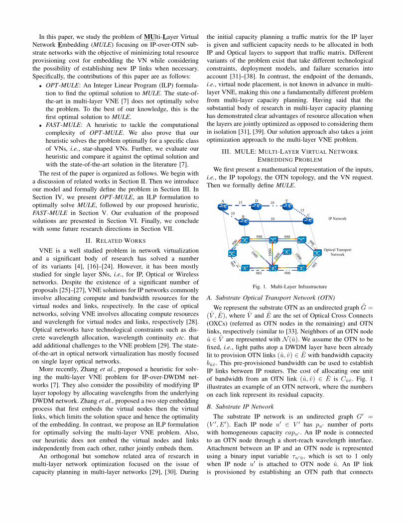
A VN request is an undirected graph G = (V , E), where Vand E are the set of virtual nodes (VNodes) and virtual links(VLinks), respectively. We assume online VN arrival, i.e., VNsarriving one at a time (similar to [5]). Each VLink (u, v) ∈ Ehas a bandwidth requirement buv . Each VNode u ∈ V has alocation constraint set L(u) ⊂ V ′ that represents the set of IPnodes where u can be embedded. We represent the locationconstraints using a binary input variable `uu′ , which is set to1 if IP node u′ ∈ L(u). Fig. 2 illustrates a VN, where thenumber on each link represents VLink demand, and the setnext to each node denotes that VNode’s location constraints.
D. Problem Definition
Given a multi-layer SN composed of an IP network G′ ontop of an OTN network G, and a VN request G with locationconstraint set L:• Map each VNode u ∈ V to an IP node u′ ∈ V ′ according
to the VNode’s location constraint.• Map each VLink (u, v) ∈ E to a path in the IP network.
This path can contain a combination of existing IP linksand newly created IP links.
• Map all newly created IP links to a path in the OTN.• The total cost of provisioning resources for new IP links
and cost of provisioning resources for VLinks should beminimized subject to the following constraints:
– IP links cannot be over-committed to accommodatethe VLinks, and
– the demand of a single VLink should be satisfied bya single IP path.
IV. OPT-MULE: AN ILP FORMULATION
A. Decision Variables
A VLink must be mapped to a path in the IP network. Thefollowing decision variable indicates the mapping between a
VLink (u, v) ∈ E and an IP link, (u′, v′, i) ∈ E′.
xuvu′v′i =
{1 if (u, v) ∈ E is mapped to (u′, v′, i) ∈ E′,0 otherwise.
The following decision variable denotes VNode mapping:
yuu′ =
{1 if u ∈ V is mapped to u′ ∈ V ′,0 otherwise.
Creation of new IP links is decided by:
γu′v′i =
{1 when i-th IP link is created between u′ and v′,0 otherwise.
Finally, a newly created IP link must be mapped to an OTNpath. This mapping is indicated by the following variable:
zu′v′i
uv =
{1 if (u′, v′, i) ∈ E′ is mapped to (u, v) ∈ E,0 otherwise.
In what follows, V ′2 denotes the set of all pairs of IP nodes(u′, v′) such that u′ 6= v′.
B. Constraints
1) VNode Mapping Constraint: (1) and (2) ensure thateach VNode is mapped to exactly one IP node according tothe location constraints. (3) restricts multiple VNodes to bemapped on the same IP Node.
∀u ∈ V , ∀u′ ∈ V ′ : yuu′ ≤ `uu′ (1)
∀u ∈ V :∑
u′∈V ′
yuu′ = 1 (2)
∀u′ ∈ V ′ :∑u∈V
yuu′ ≤ 1 (3)
2) VLink Mapping Constraints: (4) ensures that VLinks aremapped only to existing or newly created IP links. (5) ensuresthat each VLink is mapped to a non-empty subset of IP links.We prevent the formation of loops between parallel IP linksby (6). (7) prevents overcommitment of IP link bandwidth.Finally, (8), our flow-conservation constraint, ensures thatVLinks are mapped on a continuous IP path.
∀(u, v) ∈ E,∀(u′, v′) ∈ V ′2, 1 ≤ i ≤ min(pu′ , pv′) :
xuvu′v′i ≤ γu′v′i + γv′u′i + Γu′v′i (4)
∀(u, v) ∈ E :∑
∀(u′,v′)∈V ′2
pu′∑i=1
xuvu′v′i ≥ 1 (5)
∀(u, v) ∈ E,∀(u′, v′) ∈ V ′2 :
pu′∑i=1
xuvu′v′i ≤ 1 (6)
∀(u′, v′) ∈ V ′2, 1 ≤ i ≤ pu′ :∑
∀(u,v)∈E
xuvu′v′i × buv ≤ bu′v′i
(7)
∀(u, v) ∈ E,∀u′ ∈ V ′ :∑∀v′∈V ′2
min(pu′ ,pv′ )∑i=1
(xuvu′v′i − xuvv′u′i) =
yuu′ − yvu′
(8)
3) IP Link Creation Constraints: (9) limits the number ofincident IP links on an IP node to be within its availablenumber of ports. Then, (10) ensures that a specific instanceof IP link between a pair of IP nodes is either decided by theILP or was part of the input, but not both at the same time.
∀u′ ∈ V ′ :∑
∀v′∈V ′|v′ 6=u′
min(pu′ ,pv′ )∑i=1
γu′v′i + γv′u′i + Γu′v′i ≤ pu′
(9)
∀(u′, v′) ∈ V ′2, 1 ≤ i ≤ pu′ : γu′v′i + Γu′v′i ≤ 1 (10)
4) IP-to-OTN Link Mapping Constraints: First, we ensure,using (11), that only the newly created IP links are mapped onthe OTN layer. Then, (12) is the flow conservation constraintthat ensures continuity of the mapped OTN paths. Finally, (13)is our capacity constraint for OTN links.
∀(u′, v′) ∈ V ′2, 1 ≤ i ≤ pu′ , (u, v) ∈ E : zu′v′i
uv ≤ γu′v′i
(11)
∀(u′, v′) ∈ V ′2, 1 ≤ i ≤ pu′ ,∀u ∈ V :∑∀v∈N (u)
(zu′v′i
uv − zu′v′i
vu ) =
γu′v′i if τu′u = 1,−γu′v′i if τv′u = 1,
0 otherwise.(12)
∀(u, v) ∈ E :∑
∀(u′,v′)∈V ′2
pu′∑i=1
zu′v′i
uv × bu′v′i ≤ buv
(13)
C. Objective Function
Our objective is to minimize the cost incurred by creatingnew IP links and also the cost of provisioning bandwidth forthe VLinks. Cost for provisioning new IP links is computedas the cost of allocating bandwidth in the OTN paths for everynew IP link. The cost of embedding a VN is computed as thetotal cost of provisioning bandwidth on the IP links for theVLinks. Our objective function is formulated as follows:
minimize∑
∀(u′,v′)∈V ′2
pu′∑i=1
∑∀(u,v)∈E
zu′v′i
uv × bu′v′i × Cuv
+∑
∀(u,v)∈E
∑∀(u′,v′)∈V ′2
pu′∑i=1
xuvu′v′i′ × buv × Cu′v′i (14)
D. Hardness of OPT-MULE
Consider the case where the IP layer has sufficient capacityto accommodate a given VN request. In this case, MULEbecomes a single-layer VNE, which has been proven to beNP-Hard via a reduction from the multi-way separator problem[5]. Given that single-layer VNE is an instance of MULE, byrestriction we conclude that MULE is also NP-Hard.
V. FAST -MULE: A HEURISTIC APPROACH
Given the NP-Hard nature of the multi-layer VNE prob-lem and its intractability for large network instances, wepropose FAST-MULE, a heuristic to solve the Multi-LayerVNE problem. We begin by explaining the challenges behindthe design of FAST-MULE in Section V-A, followed by adescription of its procedural details and an illustrative examplein Section V-B and Section V-C, respectively. Finally, we provein Section V-D that FAST-MULE yields the optimal solutionfor star VN topologies with uniform bandwidth requirement.
A. Challenges
1) Joint Mapping in IP and OTN Layers: One challenge ofMULE is the fact that the embedding can take place in bothlayers. This occurs when a VN could not be accommodatedby the existing IP links, and requires the creation of newones. A plausible approach is to handle the embedding ateach layer separately, i.e., start by mapping the VN on theIP layer followed by mapping the new IP links on the OTNlayer. Clearly, such disjoint embedding is far from the optimalas there may not be sufficient bandwidth at the OTN level toaccommodate the new IP links. To overcome this limitation,we equip FAST-MULE with the ability to consider both layerssimultaneously when embedding a VN. This is achieved bycollapsing the IP and OTN into a single layer graph, similarto [7]. Our collapsed graph contains all the IP and OTN nodesand links, as well as the links connecting IP nodes to OTNnodes. In contrast, [7] keeps the IP links and replaces theshortest paths in OTN with potential IP links that could becreated with those paths. In our case, a VLink embeddingcontaining OTN links indicates creation of new IP links.
2) Joint VNode and VLink Embedding: Another challengeis to perform simultaneous embedding of a VNode and itsincident VLinks. Embedding VNodes independently of theirincident VLinks increases the chances of VN embeddingfailure. However, such joint embedding is hard to solve sinceit is equivalent to solving the NP-hard Multi-commodity Un-splittable Flow with Unknown Sources and Destinations [41].Our goal is to equip FAST-MULE with the ability to performjoint embedding of VNodes along with their incident VLinks.To achieve this, we augment the collapsed graph with meta-nodes and modify its link capacities to convert the VNode andVLink embedding problem into a min-cost max-flow problemthat we solve using Edmonds-Karp (EK) algorithm [42]. Theflows returned by EK indicate both the VNodes and VLinksmapping. In what follows, we elucidate the details of thistransformation along with how the embedding solution isextracted from the flows obtained from EK.
B. Heuristic Algorithm
Alg. 1 presents a high level view of FAST-MULE. Thedetails of every stage are as follows:
Stage 1: Creation of a Collapsed Graph: We begin bycollapsing the OTN and IP networks to a single-layer toachieve joint mapping at the IP and OTN layers. We keep theresidual capacities of the IP and OTN links as they are. We
Algorithm 1: Multi-Layer VNE Algorithm
Input: G = (V ,E), G′ = (V ′,E′), G = (V ,E)Output: Overlay Mapping Solution M
1 function FAST-MULE()2 /*Initialize List of Settled Nodes*/3 S = {}4 Step 1: Create Collapsed Graph5 G = CreateCollapsedGraph(G′,G)6 forall v ∈ V do7 if v ∈ S then8 continue9 S = S ∪ v
10 Step 2: Create Meta-Nodes11 M.nmap = M.nmap ∪ MapNode(v,L(v))12 for each (u ∈ N (v)) do13 if (u in S) then14 continue15 if (M.nmap(u) == NULL) then16 V = V ∪ CreateMetaNodes(L(u))17 else18 V = V ∪ CreateMetaNodes(M.nmap(u))19 Step 3: Create Ref-Nodes20 V = V ∪ CreateRefNodes(V )21 Step 4: Run Link Embedding Algorithm22 M.emap = M.emap ∪ EdmondsKarp(G)23 E = E ∪ GetNewIPLinks(M.emap)24 S = S ∪ isSettled(N (v))25 Return M;
A
B C
D E15
1010
10
15
985 990
990990
1000
(a) IP-over-OTN Graph
985, 990,
990, 990,
1000
, 10
10,1
10,1
15,1 10,1
A
B
D E
C20,1
20,1
20,1
20,120,1
15,1
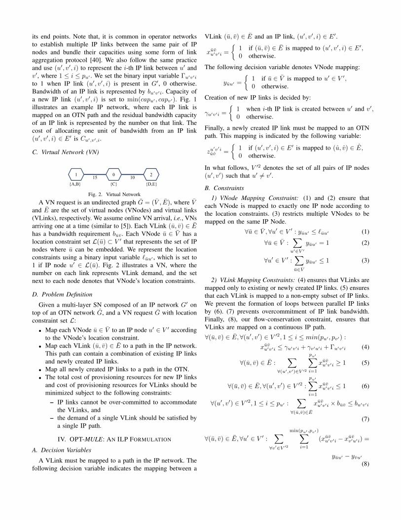
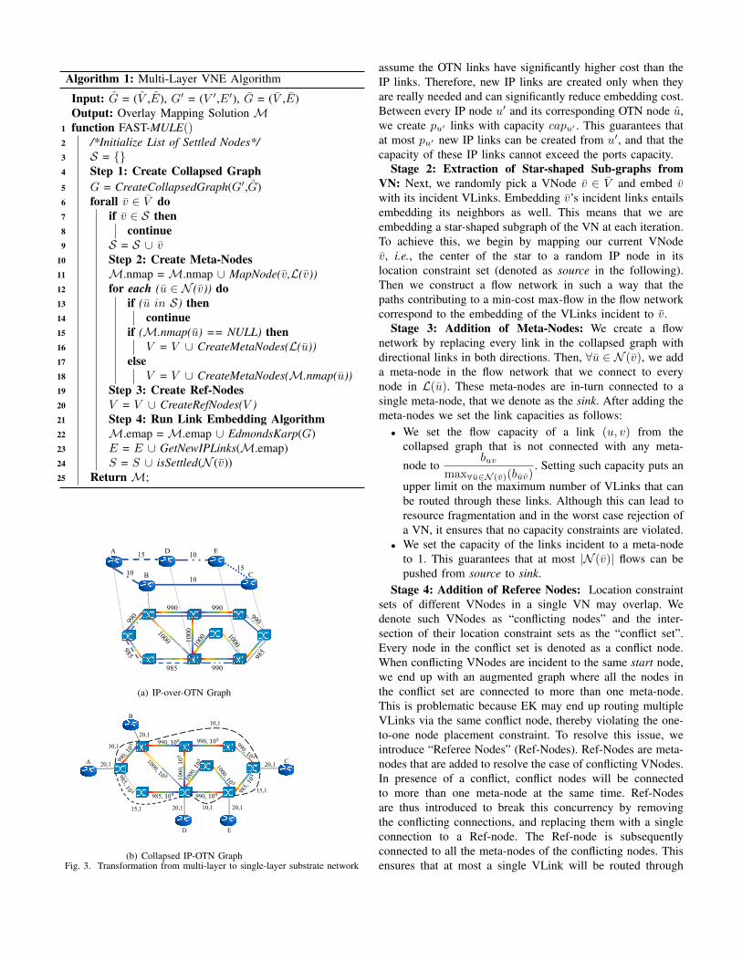
(b) Collapsed IP-OTN GraphFig. 3. Transformation from multi-layer to single-layer substrate network
assume the OTN links have significantly higher cost than theIP links. Therefore, new IP links are created only when theyare really needed and can significantly reduce embedding cost.Between every IP node u′ and its corresponding OTN node u,we create pu′ links with capacity capu′ . This guarantees thatat most pu′ new IP links can be created from u′, and that thecapacity of these IP links cannot exceed the ports capacity.
Stage 2: Extraction of Star-shaped Sub-graphs fromVN: Next, we randomly pick a VNode v ∈ V and embed vwith its incident VLinks. Embedding v’s incident links entailsembedding its neighbors as well. This means that we areembedding a star-shaped subgraph of the VN at each iteration.To achieve this, we begin by mapping our current VNodev, i.e., the center of the star to a random IP node in itslocation constraint set (denoted as source in the following).Then we construct a flow network in such a way that thepaths contributing to a min-cost max-flow in the flow networkcorrespond to the embedding of the VLinks incident to v.
Stage 3: Addition of Meta-Nodes: We create a flownetwork by replacing every link in the collapsed graph withdirectional links in both directions. Then, ∀u ∈ N (v), we adda meta-node in the flow network that we connect to everynode in L(u). These meta-nodes are in-turn connected to asingle meta-node, that we denote as the sink. After adding themeta-nodes we set the link capacities as follows:• We set the flow capacity of a link (u, v) from the
collapsed graph that is not connected with any meta-
node tobuv
max∀u∈N (v)(buv). Setting such capacity puts an
upper limit on the maximum number of VLinks that canbe routed through these links. Although this can lead toresource fragmentation and in the worst case rejection ofa VN, it ensures that no capacity constraints are violated.
• We set the capacity of the links incident to a meta-nodeto 1. This guarantees that at most |N (v)| flows can bepushed from source to sink.
Stage 4: Addition of Referee Nodes: Location constraintsets of different VNodes in a single VN may overlap. Wedenote such VNodes as “conflicting nodes” and the inter-section of their location constraint sets as the “conflict set”.Every node in the conflict set is denoted as a conflict node.When conflicting VNodes are incident to the same start node,we end up with an augmented graph where all the nodes inthe conflict set are connected to more than one meta-node.This is problematic because EK may end up routing multipleVLinks via the same conflict node, thereby violating the one-to-one node placement constraint. To resolve this issue, weintroduce “Referee Nodes” (Ref-Nodes). Ref-Nodes are meta-nodes that are added to resolve the case of conflicting VNodes.In presence of a conflict, conflict nodes will be connectedto more than one meta-node at the same time. Ref-Nodesare thus introduced to break this concurrency by removingthe conflicting connections, and replacing them with a singleconnection to a Ref-node. The Ref-node is subsequentlyconnected to all the meta-nodes of the conflicting nodes. Thisensures that at most a single VLink will be routed through
any conflict node. Further, when a conflict node is selected tohost a given VNode, no other IP nodes for the same VNodewill be selected, thereby ensuring an one-to-one assignment.
Stage 5: Execution of the Edmonds-Karp Algorithm:Now we have an instance of the max-flow problem that we willsolve using EK. We have set the capacity of the links in theflow network in such a way that EK can push at most |N (v)|flows, indicating the VLink embedding of v’s incident links.Note that the only way to push |N (v)| flows is by having eachflow traverse a unique meta-node to reach the sink. The VNodeembedding of v’s neighbors can be extracted by examiningeach flow to find the incident IP node of each meta-node. Ifany of the obtained flows is routed via an OTN path, then anew IP link is established and added to the collapsed graph.This allows subsequent iterations to use the newly created IPlink. If at any iteration EK returns less than |N (v)| flows, thisindicates an embedding failure, and the algorithm terminates.Otherwise, the algorithm returns to Stage 2 and repeats untilall the VNodes are settled.
Let I be the number of iterations of Fast-MULE. Duringeach iteration we run the EK algorithm to find min-cost max-flow. We replaced the augmenting path finding procedureof EK with Dijkstra’s shortest path algorithm. Therefore,the running time of EK becomes O(|V ||E|2 log |V |). Thisrenders the time complexity of our proposed approach toO(I|V ||E|2 log |V |). If we consider the worst-case scenariowhere the VN is in the form of a chain, and the nodes aretraversed sequentially, then I = |V | − 1, which results in aworst-case complexity of O(|V ||V ||E|2 log |V |). Note that,|V | and |E| represent the number of nodes and links in thecollapsed graph, respectively, where |V | = O(|V | + |V ′|),|E| = O(|E|+ |E′|).
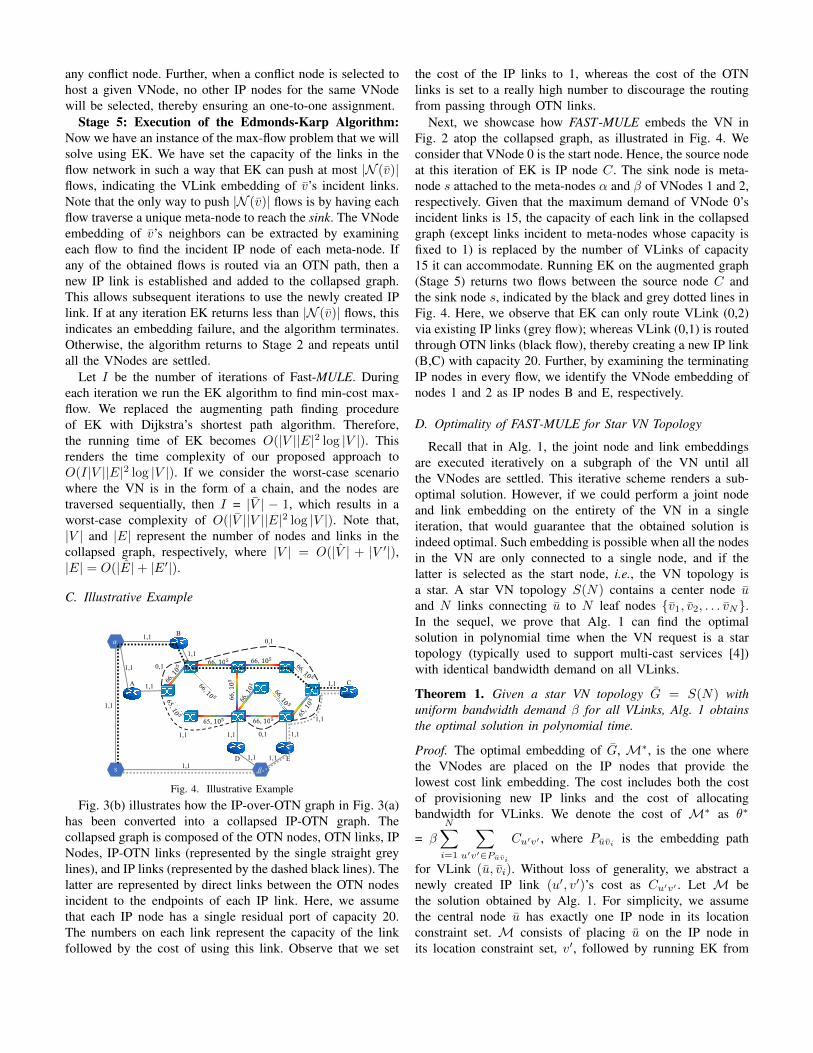
C. Illustrative Example
S
1,1 1,1
65, 66,
66, 66,
66, 10
0,1
0,1
1,1 0,1
A
B
D E
C1,1
1,1
1,1
1,11,1
1,1
1,1
1,1
1,1
1,1
Fig. 4. Illustrative Example
Fig. 3(b) illustrates how the IP-over-OTN graph in Fig. 3(a)has been converted into a collapsed IP-OTN graph. Thecollapsed graph is composed of the OTN nodes, OTN links, IPNodes, IP-OTN links (represented by the single straight greylines), and IP links (represented by the dashed black lines). Thelatter are represented by direct links between the OTN nodesincident to the endpoints of each IP link. Here, we assumethat each IP node has a single residual port of capacity 20.The numbers on each link represent the capacity of the linkfollowed by the cost of using this link. Observe that we set
the cost of the IP links to 1, whereas the cost of the OTNlinks is set to a really high number to discourage the routingfrom passing through OTN links.
Next, we showcase how FAST-MULE embeds the VN inFig. 2 atop the collapsed graph, as illustrated in Fig. 4. Weconsider that VNode 0 is the start node. Hence, the source nodeat this iteration of EK is IP node C. The sink node is meta-node s attached to the meta-nodes α and β of VNodes 1 and 2,respectively. Given that the maximum demand of VNode 0’sincident links is 15, the capacity of each link in the collapsedgraph (except links incident to meta-nodes whose capacity isfixed to 1) is replaced by the number of VLinks of capacity15 it can accommodate. Running EK on the augmented graph(Stage 5) returns two flows between the source node C andthe sink node s, indicated by the black and grey dotted lines inFig. 4. Here, we observe that EK can only route VLink (0,2)via existing IP links (grey flow); whereas VLink (0,1) is routedthrough OTN links (black flow), thereby creating a new IP link(B,C) with capacity 20. Further, by examining the terminatingIP nodes in every flow, we identify the VNode embedding ofnodes 1 and 2 as IP nodes B and E, respectively.
D. Optimality of FAST-MULE for Star VN Topology
Recall that in Alg. 1, the joint node and link embeddingsare executed iteratively on a subgraph of the VN until allthe VNodes are settled. This iterative scheme renders a sub-optimal solution. However, if we could perform a joint nodeand link embedding on the entirety of the VN in a singleiteration, that would guarantee that the obtained solution isindeed optimal. Such embedding is possible when all the nodesin the VN are only connected to a single node, and if thelatter is selected as the start node, i.e., the VN topology isa star. A star VN topology S(N) contains a center node uand N links connecting u to N leaf nodes {v1, v2, . . . vN}.In the sequel, we prove that Alg. 1 can find the optimalsolution in polynomial time when the VN request is a startopology (typically used to support multi-cast services [4])with identical bandwidth demand on all VLinks.
Theorem 1. Given a star VN topology G = S(N) withuniform bandwidth demand β for all VLinks, Alg. 1 obtainsthe optimal solution in polynomial time.
Proof. The optimal embedding of G, M∗, is the one wherethe VNodes are placed on the IP nodes that provide thelowest cost link embedding. The cost includes both the costof provisioning new IP links and the cost of allocatingbandwidth for VLinks. We denote the cost of M∗ as θ∗
= β
N∑i=1
∑u′v′∈Puvi
Cu′v′ , where Puvi is the embedding path
for VLink (u, vi). Without loss of generality, we abstract anewly created IP link (u′, v′)’s cost as Cu′v′ . Let M bethe solution obtained by Alg. 1. For simplicity, we assumethe central node u has exactly one IP node in its locationconstraint set. M consists of placing u on the IP node inits location constraint set, v′, followed by running EK from
v′ to the sink node s. EK will return the min-cost max-flowfrom v′ to the sink node s. Given that the capacity of allthe incident links to s are 1, the number of flow augmentingpaths will be at most the number of leaf nodes in G andexactly 1 unit of flow will be pushed through each of theseaugmenting paths. Therefore, upon successful embedding, EKwill return N flow augmenting paths with minimum cost θ.Now recall that the only way to push N flows towards the sinkis to traverse every meta-node once; which entails the traversalof one node from each location constraint set. The traversednodes represent the VNode embedding of all the leaf nodesin S(N). Therefore, the flow augmenting paths represent avalid embedding of S(N). We can characterize θ as, θ =N∑i=1
∑(u,v)∈Fi
Cuv × fuv , where Fi is the i-th flow augmenting
path and fuv is the flow pushed along link (u, v) in theflow network constructed from the collapsed graph. Note that,
fuv = 1, therefore, the cost becomes, θ =
N∑i=1
∑(u,v)∈Fi
Cuv . If
we can prove thatN∑i=1
∑(u,v)∈Fi
Cuv =
N∑i=1
∑u′v′∈Puvi
Cu′v′ then
our proof is complete. Since θ∗ is the optimal objective value,
let,N∑i=1
∑(u,v)∈Fi
Cuv >
N∑i=1
∑u′v′∈Puvi
Cu′v′ . Then it implies
that if we pushed the flows along the pathsN⋃i=1
Puvi (the
newly created IP links can be expanded to a set of OTNlinks to match the paths in the collapsed graph), we wouldhave obtained a lower cost solution to min-cost max-flowproblem, which contradicts that θ is the minimum cost of ourmin-cost max-flow problem for the converted flow network.
Therefore,N∑i=1
∑(u,v)∈Fi
Cuv =
N∑i=1
∑u′v′∈Puvi
Cu′v′ , completing
our proof.
If the central node, u, has more than one candidate node inits location constraint set, then running Alg. 1 |L(u)| times issufficient to obtain the lowest cost mapping solution, and therunning time of Alg. 1 still remains polynomial.
VI. EVALUATION RESULTS
We evaluate our proposed solutions for MULE throughsimulations. Due to the lack of publicly available multi-layer network topologies, we generate synthetic topologieswith varying sizes for our performance evaluation. We firstdescribe our simulation setup in Section VI-A and the eval-uation metrics in Section VI-B. Our evaluation is performedbased on the following scenarios: (i) cost comparison betweenFAST-MULE and OPT-MULE to evaluate how well FAST-MULE compares to the optimal, and (ii) comparison of FAST-MULE with the state-of-the-art heuristic [7] for solving multi-layer VNE problem.
A. Simulation Setup
1) Testbed: We have implemented OPT-MULE and FAST-MULE using IBM ILOG CPLEX 12.5 C++ libraries and Java,respectively. OPT-MULE was run on a machine with 4×8core 2.4Ghz Intel Xeon E5-4640 CPU and 512GB of memory,whereas, we used a machine with 2×8 core 2Ghz Intel XeonE5-2650 CPU and 256GB memory to evaluate FAST-MULE.
2) Network Topologies: As previously mentioned, we syn-thetically generated random graphs for both SN and VN. Wegenerated OTNs by varying the size between 15–100 nodes.For each OTN, we generated an IP topology with a nodecount of 60% of that of the OTN and a link generationprobability chosen to match the average nodal degree of knownISP topologies [43]. OTN links were assigned a capacity of100Gbps, while IP links were assigned a random capacitybetween 10–20Gbps. For each combination of IP and OTN,we generated 20 VNs with 4–8 VNodes and a 0.5 probabilityof having a link between every pair of VNodes.
B. Evaluation Metrics
1) Cost Ratio: This is the ratio of costs obtained by twodifferent approaches for solving the same problem instance.Cost is computed using (14) and measures the relative perfor-mance of two approaches.
2) Execution Time: The time required for an algorithm tosolve one instance of MULE.
C. Comparison of FAST-MULE with OPT-MULE
0.4
0.5
0.6
0.7
0.8
0.9
1
1.2 1.5 1.8 2.1 2.4 2.7 3 3.3 3.6
CDF
Cost Ratio (FAST-MULE : OPT-MULE)
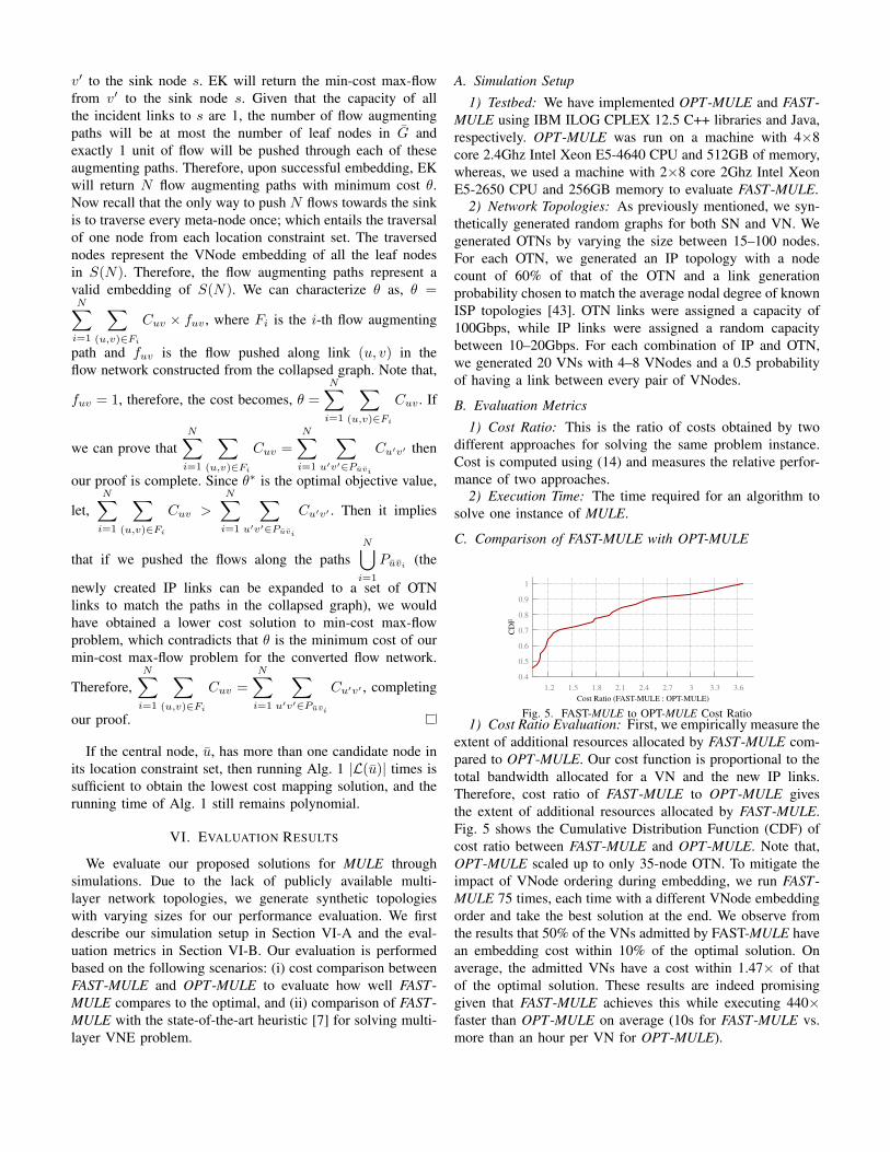
Fig. 5. FAST-MULE to OPT-MULE Cost Ratio1) Cost Ratio Evaluation: First, we empirically measure the
extent of additional resources allocated by FAST-MULE com-pared to OPT-MULE. Our cost function is proportional to thetotal bandwidth allocated for a VN and the new IP links.Therefore, cost ratio of FAST-MULE to OPT-MULE givesthe extent of additional resources allocated by FAST-MULE.Fig. 5 shows the Cumulative Distribution Function (CDF) ofcost ratio between FAST-MULE and OPT-MULE. Note that,OPT-MULE scaled up to only 35-node OTN. To mitigate theimpact of VNode ordering during embedding, we run FAST-MULE 75 times, each time with a different VNode embeddingorder and take the best solution at the end. We observe fromthe results that 50% of the VNs admitted by FAST-MULE havean embedding cost within 10% of the optimal solution. Onaverage, the admitted VNs have a cost within 1.47× of thatof the optimal solution. These results are indeed promisinggiven that FAST-MULE achieves this while executing 440×faster than OPT-MULE on average (10s for FAST-MULE vs.more than an hour per VN for OPT-MULE).
0 5
10 15 20 25 30 35
15 20 25 30 35100
101
102
103
104
FAST
-MU
LEEx
ecut
ion
Tim
e (s
ec)
OPT
-MU
LEEx
ecut
ion
Tim
e (s
ec)
OTN Node Count
OPT-MULEFAST-MULE
Fig. 6. Comparison of Execution Time
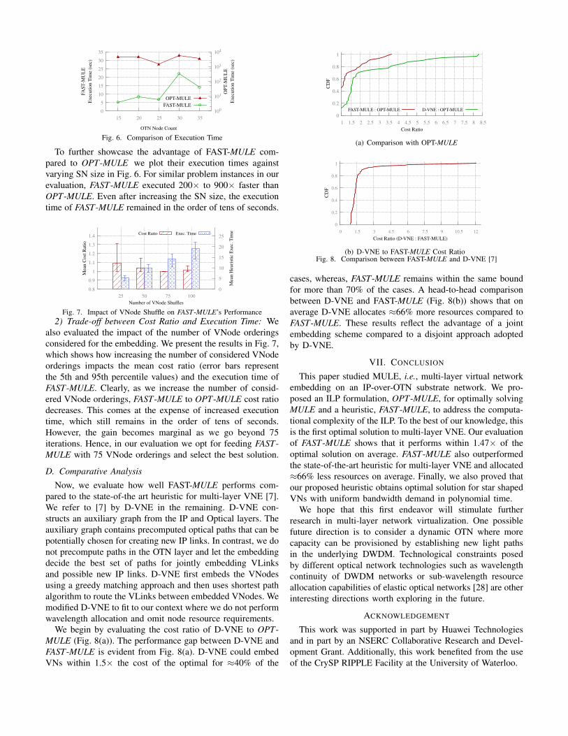
To further showcase the advantage of FAST-MULE com-pared to OPT-MULE we plot their execution times againstvarying SN size in Fig. 6. For similar problem instances in ourevaluation, FAST-MULE executed 200× to 900× faster thanOPT-MULE. Even after increasing the SN size, the executiontime of FAST-MULE remained in the order of tens of seconds.
0.8
0.9
1
1.1
1.2
1.3
1.4
25 50 75 100 0
5
10
15
20
25
Mea
n Co
st Ra
tio
Mea
n H
euris
tic E
xec.
Tim
e
Number of VNode Shuffles
Cost Ratio Exec. Time
Fig. 7. Impact of VNode Shuffle on FAST-MULE’s Performance2) Trade-off between Cost Ratio and Execution Time: We
also evaluated the impact of the number of VNode orderingsconsidered for the embedding. We present the results in Fig. 7,which shows how increasing the number of considered VNodeorderings impacts the mean cost ratio (error bars representthe 5th and 95th percentile values) and the execution time ofFAST-MULE. Clearly, as we increase the number of consid-ered VNode orderings, FAST-MULE to OPT-MULE cost ratiodecreases. This comes at the expense of increased executiontime, which still remains in the order of tens of seconds.However, the gain becomes marginal as we go beyond 75iterations. Hence, in our evaluation we opt for feeding FAST-MULE with 75 VNode orderings and select the best solution.
D. Comparative Analysis
Now, we evaluate how well FAST-MULE performs com-pared to the state-of-the art heuristic for multi-layer VNE [7].We refer to [7] by D-VNE in the remaining. D-VNE con-structs an auxiliary graph from the IP and Optical layers. Theauxiliary graph contains precomputed optical paths that can bepotentially chosen for creating new IP links. In contrast, we donot precompute paths in the OTN layer and let the embeddingdecide the best set of paths for jointly embedding VLinksand possible new IP links. D-VNE first embeds the VNodesusing a greedy matching approach and then uses shortest pathalgorithm to route the VLinks between embedded VNodes. Wemodified D-VNE to fit to our context where we do not performwavelength allocation and omit node resource requirements.
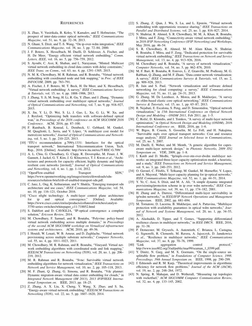
We begin by evaluating the cost ratio of D-VNE to OPT-MULE (Fig. 8(a)). The performance gap between D-VNE andFAST-MULE is evident from Fig. 8(a). D-VNE could embedVNs within 1.5× the cost of the optimal for ≈40% of the
0
0.2
0.4
0.6
0.8
1
1 1.5 2 2.5 3 3.5 4 4.5 5 5.5 6 6.5 7 7.5 8 8.5
CDF
Cost Ratio
FAST-MULE : OPT-MULE D-VNE : OPT-MULE
(a) Comparison with OPT-MULE
0
0.2
0.4
0.6
0.8
1
0 1.5 3 4.5 6 7.5 9 10.5 12
CDF
Cost Ratio (D-VNE : FAST-MULE)
(b) D-VNE to FAST-MULE Cost RatioFig. 8. Comparison between FAST-MULE and D-VNE [7]
cases, whereas, FAST-MULE remains within the same boundfor more than 70% of the cases. A head-to-head comparisonbetween D-VNE and FAST-MULE (Fig. 8(b)) shows that onaverage D-VNE allocates ≈66% more resources compared toFAST-MULE. These results reflect the advantage of a jointembedding scheme compared to a disjoint approach adoptedby D-VNE.
VII. CONCLUSION
This paper studied MULE, i.e., multi-layer virtual networkembedding on an IP-over-OTN substrate network. We pro-posed an ILP formulation, OPT-MULE, for optimally solvingMULE and a heuristic, FAST-MULE, to address the computa-tional complexity of the ILP. To the best of our knowledge, thisis the first optimal solution to multi-layer VNE. Our evaluationof FAST-MULE shows that it performs within 1.47× of theoptimal solution on average. FAST-MULE also outperformedthe state-of-the-art heuristic for multi-layer VNE and allocated≈66% less resources on average. Finally, we also proved thatour proposed heuristic obtains optimal solution for star shapedVNs with uniform bandwidth demand in polynomial time.
We hope that this first endeavor will stimulate furtherresearch in multi-layer network virtualization. One possiblefuture direction is to consider a dynamic OTN where morecapacity can be provisioned by establishing new light pathsin the underlying DWDM. Technological constraints posedby different optical network technologies such as wavelengthcontinuity of DWDM networks or sub-wavelength resourceallocation capabilities of elastic optical networks [28] are otherinteresting directions worth exploring in the future.
ACKNOWLEDGEMENT
This work was supported in part by Huawei Technologiesand in part by an NSERC Collaborative Research and Devel-opment Grant. Additionally, this work benefited from the useof the CrySP RIPPLE Facility at the University of Waterloo.
REFERENCES
[1] X. Zhao, V. Vusirikala, B. Koley, V. Kamalov, and T. Hofmeister, “Theprospect of inter-data-center optical networks,” IEEE CommunicationsMagazine, vol. 51, no. 9, pp. 32–38, 2013.
[2] N. Ghani, S. Dixit, and T.-S. Wang, “On ip-over-wdm integration,” IEEECommunications Magazine, vol. 38, no. 3, pp. 72–84, 2000.
[3] J. F. Botero, X. Hesselbach, M. Duelli, D. Schlosser, A. Fischer, andH. De Meer, “Energy efficient virtual network embedding,” Comm.Letters, IEEE, vol. 16, no. 5, pp. 756–759, 2012.
[4] S. Ayoubi, C. Assi, K. Shaban, and L. Narayanan, “Minted: Multicastvirtual network embedding in cloud data centers with delay constraints,”IEEE Trans. on Comm., vol. 63, no. 4, pp. 1291–1305, 2015.
[5] N. M. K. Chowdhury, M. R. Rahman, and R. Boutaba, “Virtual networkembedding with coordinated node and link mapping,” in Proc. of IEEEINFOCOM, 2009, pp. 783–791.
[6] A. Fischer, J. F. Botero, M. T. Beck, H. De Meer, and X. Hesselbach,“Virtual network embedding: A survey,” IEEE Communications Surveys& Tutorials, vol. 15, no. 4, pp. 1888–1906, 2013.
[7] J. Zhang, Y. Ji, M. Song, H. Li, R. Gu, Y. Zhao, and J. Zhang, “Dynamicvirtual network embedding over multilayer optical networks,” Journalof Optical Communications and Networking, vol. 7, no. 9, pp. 918–927,2015.
[8] X. Jin, Y. Li, D. Wei, S. Li, J. Gao, L. Xu, G. Li, W. Xu, andJ. Rexford, “Optimizing bulk transfers with software-defined opticalwan,” in Proceedings of the 2016 conference on ACM SIGCOMM 2016Conference. ACM, 2016, pp. 87–100.
[9] F. Rambach, B. Konrad, L. Dembeck, U. Gebhard, M. Gunkel,M. Quagliotti, L. Serra, and V. Lopez, “A multilayer cost model formetro/core networks,” Journal of Optical Communications and Network-ing, vol. 5, no. 3, pp. 210–225, 2013.
[10] “ITU-t recommendation g.709/y.1331: Interfaces for the opticaltransport network,” International Telecommunication Union, Tech.Rep., 2016. [Online]. Available: http://www.itu.int/rec/T-REC-G.709/
[11] A. L. Chiu, G. Choudhury, G. Clapp, R. Doverspike, M. Feuer, J. W.Gannett, J. Jackel, G. T. Kim, J. G. Klincewicz, T. J. Kwon et al., “Archi-tectures and protocols for capacity efficient, highly dynamic and highlyresilient core networks [invited],” Journal of Optical Communicationsand Networking, vol. 4, no. 1, pp. 1–14, 2012.
[12] “OpenFlow-enabled Transport SDN,”https://www.opennetworking.org/images/stories/downloads/sdn-resources/solution-briefs/sb-of-enabled-transport-sdn.pdf.
[13] C. Janz, L. Ong, K. Sethuraman, and V. Shukla, “Emerging transport sdnarchitecture and use cases,” IEEE Communications Magazine, vol. 54,no. 10, pp. 116–121, October 2016.
[14] “Cisco nlight technology: A multi-layer control plane architecturefor ip and optical convergence.” [Online]. Available:https://www.cisco.com/c/en/us/products/collateral/switches/catalyst-3750-series-switches/whitepaper c11-718852.html
[15] S. Dahlfort and D. CAVIGLIA, “IP-optical convergence: a completesolution,” Ericsson Review, 2014.
[16] M. Chowdhury, F. Samuel, and R. Boutaba, “Polyvine: policy-basedvirtual network embedding across multiple domains,” in Proceedingsof the second ACM SIGCOMM workshop on Virtualized infrastructuresystems and architectures. ACM, 2010, pp. 49–56.
[17] I. Houidi, W. Louati, W. B. Ameur, and D. Zeghlache, “Virtual networkprovisioning across multiple substrate networks,” Computer Networks,vol. 55, no. 4, pp. 1011–1023, 2011.
[18] M. Chowdhury, M. R. Rahman, and R. Boutaba, “Vineyard: Virtual net-work embedding algorithms with coordinated node and link mapping,”IEEE/ACM Transactions on Networking (TON), vol. 20, no. 1, pp. 206–219, 2012.
[19] M. R. Rahman and R. Boutaba, “Svne: Survivable virtual networkembedding algorithms for network virtualization,” IEEE Transactions onNetwork and Service Management, vol. 10, no. 2, pp. 105–118, 2013.
[20] M. F. Zhani, Q. Zhang, G. Simona, and R. Boutaba, “Vdc planner:Dynamic migration-aware virtual data center embedding for clouds,” inIntegrated Network Management (IM 2013), 2013 IFIP/IEEE Interna-tional Symposium on. IEEE, 2013, pp. 18–25.
[21] Z. Zhang, A. X. Liu, X. Cheng, Y. Wang, X. Zhao, and S. Su,“Energy-aware virtual network embedding,” IEEE/ACM Transactions onNetworking (TON), vol. 22, no. 5, pp. 1607–1620, 2014.
[22] S. Zhang, Z. Qian, J. Wu, S. Lu, and L. Epstein, “Virtual networkembedding with opportunistic resource sharing,” IEEE Transactions onParallel and Distributed Systems, vol. 25, no. 3, pp. 816–827, 2014.
[23] N. Shahriar, R. Ahmed, S. R. Chowdhury, M. M. A. Khan, R. Boutaba,J. Mitra, and F. Zeng, “Connectivity-aware virtual network embedding,”in 2016 IFIP Networking Conference (IFIP Networking) and Workshops,May 2016, pp. 46–54.
[24] S. R. Chowdhury, R. Ahmed, M. M. Alam Khan, N. Shahriar,R. Boutaba, J. Mitra, and F. Zeng, “Dedicated protection for survivablevirtual network embedding,” IEEE Transactions on Network and ServiceManagement, vol. 13, no. 4, pp. 913–926, 2016.
[25] M. Chowdhury and R. Boutaba, “A survey of network virtualization,”Computer Networks, vol. 54, no. 5, pp. 862–876, 2010.
[26] M. F. Bari, R. Boutaba, R. Esteves, L. Z. Granville, M. Podlesny, M. G.Rabbani, Q. Zhang, and M. F. Zhani, “Data center network virtualization:A survey,” IEEE Communications Surveys & Tutorials, vol. 15, no. 2,pp. 909–928, 2013.
[27] R. Jain and S. Paul, “Network virtualization and software definednetworking for cloud computing: a survey,” IEEE CommunicationsMagazine, vol. 51, no. 11, pp. 24–31, 2013.
[28] G. Zhang, M. De Leenheer, A. Morea, and B. Mukherjee, “A surveyon ofdm-based elastic core optical networking,” IEEE CommunicationsSurveys & Tutorials, vol. 15, no. 1, pp. 65–87, 2013.
[29] R. Nejabati, E. Escalona, S. Peng, and D. Simeonidou, “Optical networkvirtualization,” in 15th International Conference on Optical NetworkDesign and Modeling - ONDM 2011, Feb 2011, pp. 1–5.
[30] C. Rozic, D. Klonidis, and I. Tomkos, “A survey of multi-layer networkoptimization,” in Optical Network Design and Modeling (ONDM), 2016International Conference on. IEEE, 2016, pp. 1–6.
[31] W. Bigos, B. Cousin, S. Gosselin, M. Le Foll, and H. Nakajima,“Survivable mpls over optical transport networks: Cost and resourceusage analysis,” IEEE Journal on Selected Areas in Communications,vol. 25, no. 5, 2007.
[32] M. Duelli, E. Weber, and M. Menth, “A generic algorithm for capex-aware multi-layer network design,” in Photonic Networks, 2009 ITGSymposium on. VDE, 2009, pp. 1–8.
[33] I. Katib and D. Medhi, “Ip/mpls-over-otn-over-dwdm multilayer net-works: an integrated three-layer capacity optimization model, a heuristic,and a study,” IEEE Transactions on Network and Service Management,vol. 9, no. 3, pp. 240–253, 2012.
[34] O. Gerstel, C. Filsfils, T. Telkamp, M. Gunkel, M. Horneffer, V. Lopez,and A. Mayoral, “Multi-layer capacity planning for ip-optical networks,”IEEE Communications Magazine, vol. 52, no. 1, pp. 44–51, 2014.
[35] Y. Ye, C. Assi, S. Dixit, and M. A. Ali, “A simple dynamic integratedprovisioning/protection scheme in ip over wdm networks,” IEEE Com-munications Magazine, vol. 39, no. 11, pp. 174–182, 2001.
[36] H. Zhang and A. Durresi, “Differentiated multi-layer survivability inip/wdm networks,” in IEEE/IFIP Network Operations and ManagementSymposium. IEEE, 2002, pp. 681–694.
[37] M. Tornatore, D. Lucerna, B. Mukherjee, and A. Pattavina, “Multilayerprotection with availability guarantees in optical wdm networks,” Jour-nal of Network and Systems Management, vol. 20, no. 1, pp. 34–55,2012.
[38] A. Alashaikh, D. Tipper, and T. Gomes, “Supporting differentiatedresilience classes in multilayer networks,” in IEEE DRCN. IEEE, 2016,pp. 31–38.
[39] P. Demeester, M. Gryseels, A. Autenrieth, C. Brianza, L. Castagna,G. Signorelli, R. Clemenfe, M. Ravera, A. Jajszczyk, D. Janukowiczet al., “Resilience in multilayer networks,” IEEE CommunicationsMagazine, vol. 37, no. 8, pp. 70–76, 1999.
[40] “Link aggregation control protocol,”http://www.ieee802.org/3/ad/public/mar99/seaman 1 0399.pdf.
[41] Y. Dinitz, N. Garg, and M. X. Goemans, “On the single-source un-splittable flow problem,” in Foundations of Computer Science, 1998.Proceedings. 39th Annual Symposium on. IEEE, 1998, pp. 290–299.
[42] J. Edmonds and R. M. Karp, “Theoretical improvements in algorithmicefficiency for network flow problems,” Journal of the ACM (JACM),vol. 19, no. 2, pp. 248–264, 1972.
[43] N. Spring, R. Mahajan, and D. Wetherall, “Measuring isp topologieswith rocketfuel,” ACM SIGCOMM Computer Communication Review,vol. 32, no. 4, pp. 133–145, 2002.