Embed Size (px)
Citation preview
Multi
Test
1000
U
ser’
Man
ual
Release EN 1.00 of the 17/09/2002
Copyright Amprobe 2002

AMPROBE MULTITEST1000
Index: 1. SAFETY PRECAUTIONS AND PROCEDURES ........................................................3
1.1. PRELIMINARY INSTRUCTIONS ......................................................................................3 1.2. DURING USE ....................................................................................................................4 1.3. AFTER USE.......................................................................................................................4
2. GENERAL DESCRIPTION .........................................................................................5 2.1. FUNCTIONS......................................................................................................................5 2.2. INSTRUMENT DESCRIPTION..........................................................................................6
3. PREPARATION FOR USE .........................................................................................8 3.1. INITIAL CONTROL ............................................................................................................8 3.2. POWER SUPPLY ..............................................................................................................8 3.3. CALIBRATION...................................................................................................................8 3.4. STORAGE .........................................................................................................................8 3.5. HOW TO SET LANGUAGE AND MEASUREMENT UNIT ................................................9
4. DESCRIPTION OF THE ROTARY SWITCH FUNCTIONS.......................................11 4.1. LOWΩ: CONTINUITY TEST OF EARTH, PROTECTIVE AND EQUALIZING
POTENTIAL CONDUCTORS ..........................................................................................11 4.1.1. MODE "CAL" ...............................................................................................................................12 4.1.2. PROCEDURE FOR MEASURING CONTINUITY OF EQUALIZING POTENTIAL CONDUCTORS MODE "AUTO",
"R+TIMER", "R-TIMER".............................................................................................................14 4.1.3. ANOMALOUS CASES DURING "AUTO", "R+TIMER", "R-TIMER" TESTS..........................................16
4.2. MΩ: INSULATION RESISTANCE MEASUREMENT WITH TEST VOLTAGE OF 50V, 100V, 250V, 500V OR 1000V ....................................................................................18
4.2.1. PROCEDURE FOR MEASURING INSULATION RESISTANCE IN ANY MODE .............................................19 4.2.2. SPECIAL CASES WHICH MAY OCCUR DURING THE TESTS "MAN" & "TIMER" ....................................24
4.3 : PHASE SEQUENCE INDICATOR ...........................................................................25 .4.3.1. MODE " " ................................................................................................................................26 4.3.2. ANOMALOUS CASES WHICH MAY OCCUR DURING PHASE SEQUENCE TESTS ......................................28
4.4. EARTH ρ: EARTH RESISTANCE AND RESISTIVITY MEASUREMENT.......................30 4.4.1. MEASUREMENT PROCEDURE FOR "2P" TEST MODE ........................................................................31 4.4.2. MEASUREMENT PROCEDURE FOR "3P" TEST MODE ........................................................................35 4.4.3. MEASUREMENT PROCEDURE FOR "ρ" TEST MODE ..........................................................................38 4.4.4. ANOMALOUS CASES WHICH MAY OCCUR DURING EARTH ρ TESTS..................................................40
5. HOW TO SAVE, RECALL AND CLEAR DATA STORED IN MEMORY..................42 5.1. SAVE: "SAVE" KEY.........................................................................................................42 5.2. RECALL: "RCL" KEY.......................................................................................................43 5.3. CLEAR: "CLR" KEY.........................................................................................................44
6. RESET OF THE INSTRUMENT AND DEFAULT PARAMETERS ...........................46 6.1. RESET PROCEDURE.....................................................................................................46 6.2. DEFAULT PARAMETERS...............................................................................................46
7. INSTRUMENT CONNECTION TO A PC ..................................................................47 8. MAINTENANCE........................................................................................................48
8.1. GENERAL........................................................................................................................48 8.2. BATTERY REPLACEMENT ............................................................................................48 8.3. INSTRUMENT CLEANING..............................................................................................48
9. TECHNICAL SPECIFICATIONS...............................................................................49 9.1. TECHNICAL FEATURES ................................................................................................49
9.1.1. SAFETY STANDARDS ....................................................................................................................51 9.1.2. GENERAL SPECIFICATIONS ...........................................................................................................51
9.2. ENVIRONMENT ..............................................................................................................52 9.2.1. ENVIRONMENTAL WORKING CONDITIONS .......................................................................................52 9.2.2. EMC...........................................................................................................................................52
9.3. ACCESSORIES...............................................................................................................52 10. SERVICE...................................................................................................................53
10.1. WARRANTY CONDITIONS.............................................................................................53 11. PRACTICAL REPORTS FOR ELECTRICAL TESTS...............................................54
11.1. LOWΩ: CONTINUITY MEASUREMENT ON PROTECTIVE CONDUCTORS................54
EN - 1

AMPROBE MULTITEST1000
11.2. INSULATION RESISTANCE MEASUREMENT OF THE ELECTRICAL INSTALLATIONS (250VDC, 500VDC, 1000VDC)........................................................................................55
11.3. MEASUREMENT OF FLOOR INSULATION RESISTANCE IN MEDICAL ROOMS.......57 11.4. CHECK OF THE CIRCUIT SEPARATION ......................................................................58 11.5 EARTH RESISTANCE MEASUREMENT, VOLTAMPEROMETRIC METHOD ..............61 11.6 EARTH RESISTIVITY MEASUREMENT.........................................................................63
Release EN 1.00 of the 17/09/2002
EN - 2

1. SAFETY PRECAUTIONS AND PROCEDURES This instrument conforms to safety standards EN61557 and EN 61010-1 relating to electronic measuring instruments.
WARNING
For your own safety as well as that of the instrument you are recommended to follow the procedures described in this instruction manual and carefully read all the notes preceded by the symbol .
Strictly adhere to the following instructions before and during measurements:
Do not take measurements in wet environments. Do not take measurements in environments with explosive gas, fuels or dust. Keep yourself insulated from the object under test. Avoid any contact with exposed metal parts, ends of test leads not in use, circuits, etc. Do not take any measurements in the case of unusual conditions of the instrument
such as deformation, breakage, leakage of substances, absence of displayed readings etc.
Pay careful attention when measuring voltages exceeding 25V in particular places (building yards, swimming pools...) and 50V in ordinary places because of the risk of electric shock.
The following symbols are used in this manual:
Caution: refer to the instructions reported in this manual; improper use may damage the apparatus or its components.
AC Voltage or Current.
Unidirectional pulsating Voltage or Current.
Rotary switch of the instrument.
1.1. PRELIMINARY INSTRUCTIONS
This instrument has been designed for use in environments with a pollution degree 2. It can be used for tests on electrical installations with over voltage category III up to
265V (to Earth). You are recommended to comply with the standard safety regulations aimed at:
Protecting you against dangerous currents. Protecting the instrument against improper use.
Only the leads supplied with the instrument guarantee compliance with the safety standards. They must be in good condition and must be replaced, if necessary, with identical models.
Do not take measurements on circuits exceeding the specified voltage limits.

Do not take any measurement under environmental conditions beyond the limits specified in this manual.
Check that batteries have been installed correctly. Before connecting test leads to the circuit under test, check that the rotary switch
position is correct. Check that the display and rotary switch indicate the same function.
1.2. DURING USE Carefully read the following recommendations and instructions:
WARNING
Non-compliance with the Warnings and/or Instructions may damage the apparatus and/or its components or injure the operator.
Before selecting any function disconnect the test leads from the circuit under test. When the instrument is connected to the tested circuit never touch any test lead that is
not being used. Avoid taking resistance measurements in the presence of external voltages; even
though the instrument is protected, a high voltage may cause malfunctions.
WARNING
If the symbol is displayed during use interrupt testing and replace batteries following the procedure described under paragraph 8.2. The instrument is capable of keeping the data stored even though batteries are not installed.
1.3. AFTER USE
When the measurements are completed disconnect the test leads from the circuit under test and after that switch OFF the instrument.
Remove batteries when the apparatus remains unused for long periods of time.

2. GENERAL DESCRIPTION Dear Customer, we thank you for your patronage. The instrument you have just purchased will grant you accurate and reliable measurements provided that it is used according to the present manual’s instructions. The instrument was designed to grant the user the utmost safety conditions thanks to a new concept assuring double insulation and over voltage category III. 2.1. FUNCTIONS
LOWΩ: Continuity test of earth, protective and equalizing potential conductors with test current greater than 200mA and open circuit voltage ranging from 4V to 24V.
RISO: Measurement of insulation resistance with DC test voltage 50V, 100V, 250V, 500V or 1000V.
: Indication of phase sequence. EARTH ρ: Measurement of earth resistance and earth resistivity. RS232: Rotary switch position for RS232 communications.

2.2. INSTRUMENT DESCRIPTION
1
2
3
DISP
RCL ESC
SAVE
CLR
START STOP
FUNC Un/I∆n DIST
S
UL
LEGEND: 1. Display 2. Function keys 3. Rotary switch
FUNC FUNCTION key to select measuring mode.
Un / DIST key for selection of rated voltage or distance depending on which measurement is selected.
Un DIST
key for increasing the test duration interval or to scroll the results of the stored tests.
key for decreasing the test duration interval or to scroll the results of the stored tests.
ON/OFF key. Keep it pressed a few seconds switch off the instrument. Release when beep sounds.
DISP
START STOP
START/STOP key for start or to stop tests.
DISPLAY key to display the stored results.
CLR CLEAR key to cancel the stored results.
RCL ESC
RECALL/ESCAPE key to recall the stored tests (RCL) and leave the selected function or mode (ESC).

SAVE SAVE key to save tests.
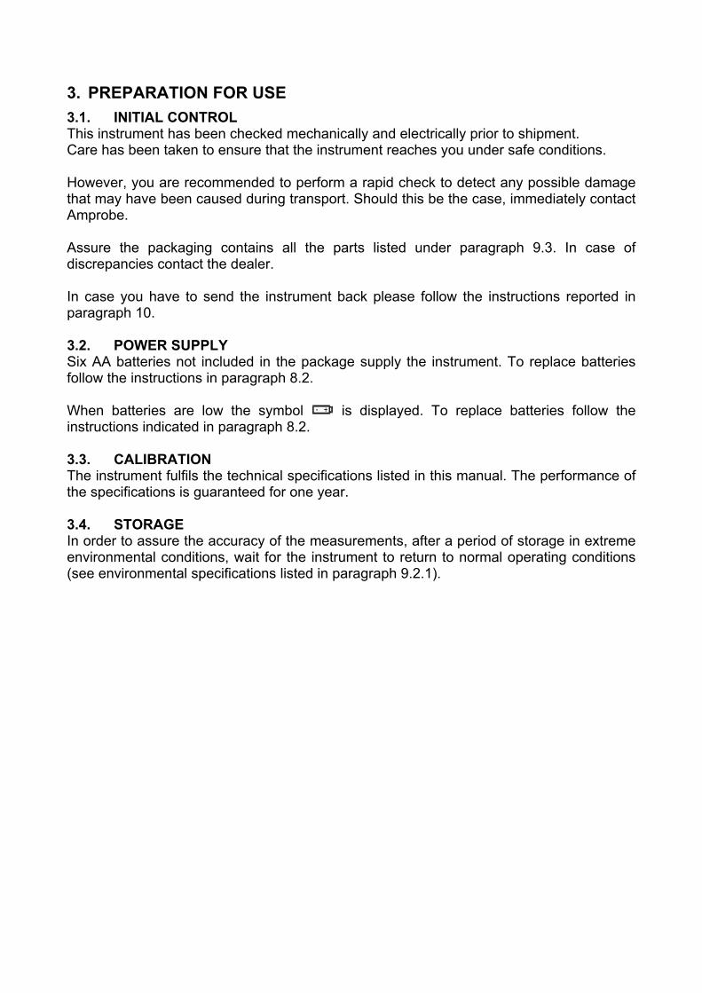
3. PREPARATION FOR USE 3.1. INITIAL CONTROL This instrument has been checked mechanically and electrically prior to shipment. Care has been taken to ensure that the instrument reaches you under safe conditions. However, you are recommended to perform a rapid check to detect any possible damage that may have been caused during transport. Should this be the case, immediately contact Amprobe. Assure the packaging contains all the parts listed under paragraph 9.3. In case of discrepancies contact the dealer. In case you have to send the instrument back please follow the instructions reported in paragraph 10. 3.2. POWER SUPPLY Six AA batteries not included in the package supply the instrument. To replace batteries follow the instructions in paragraph 8.2. When batteries are low the symbol is displayed. To replace batteries follow the instructions indicated in paragraph 8.2. 3.3. CALIBRATION The instrument fulfils the technical specifications listed in this manual. The performance of the specifications is guaranteed for one year. 3.4. STORAGE In order to assure the accuracy of the measurements, after a period of storage in extreme environmental conditions, wait for the instrument to return to normal operating conditions (see environmental specifications listed in paragraph 9.2.1).

3.5. HOW TO SET LANGUAGE AND MEASUREMENT UNIT It is possible to set the language and the distance measurement unit (in earth resistivity) by following this procedure: 1. While pressing the FUNC button switch ON the instrument (the rotary switch position
isn't relevant). 2.
LA E
The following screen will appear.
3. Choose the desired language between English, Spanish, German and Italian by
pressing the and keys (appear En, ES, dE, IT). 4.
Push the SAVE key confirming the choice. The instrument will display the following screen.
OK LA
E
Push ESC key leaving language selection menu without confirming any change.
5.
le
m
The instrument will display the following screen.
6. Choose the desired distance measurement unit between meter and feet that change by
pushing and keys (appear m and ft). 7.

Push SAVE key confirming the choice. The instrument will display the following screen.
le
m OK
Push ESC key leaving this menu without confirming any change.

4. DESCRIPTION OF THE ROTARY SWITCH FUNCTIONS 4.1. LOWΩ: CONTINUITY TEST OF EARTH RESISTIVITY, PROTECTIVE AND
EQUALIZING POTENTIAL CONDUCTORS The measurement is performed with a test current greater than 200 mA and open circuit voltage ranging from 4 to 24V DC according to EN 61557-2 and VDE 0413 part 4.
WARNING
Before carrying out the continuity test make sure that there is no voltage at the ends of the conductor under test.
Turn the rotary knob to the LOWΩ position.
Switch on the instrument.
The FUNC key permits you to select one of the following measuring modes: FUNC AUTO mode (the instrument carries out two measurements with reversed
polarity R+ and R-, and displays their average value Ravg). This mode is recommended for the continuity test.
R + TIMER mode (measurement with positive polarity and the ability to set the duration time of the test). In this case the operator can set a measuring time long enough to permit him to move the protective conductors while the instrument is carrying out the test to detect any bad connection.
R – TIMER mode (measurement with negative polarity and the ability to set the duration time of the test). In this case the operator can set a measuring time long enough to permit him to move the protective conductors while the instrument is carrying out the test to detect any bad connection.
Mode CAL (compensation of the resistance of the cables used for the measurement).
Note: If the resistance is lower than 5Ω (including the resistance of the calibration) the
continuity test is performed by the instrument with a current greater than 200mA. If the resistance is greater than 5Ω, the continuity test is performed by the instrument using a decreasing current.

4.1.1. "CAL" Mode 1. Select the CAL mode using the FUNC key. 2. Connect the black and blue cables to the instrument input terminals T1 and T4
respectively:
B2 B3 B4B1
Connection of instrument terminals during calibration procedure. 3. If the cables supplied with the instrument are not long enough for the measurement you can
extend the blue cable. 4. Connect the alligator clips to the cable terminals. 5. Short-circuit the measuring cable ends making sure that the conductive parts of the alligator
clips make a good contact with each other (see previous picture).
6. Press the START/STOP key. The instrument carries out the calibration. START STOP
CAL LOWΩ 0.00
Ω
203 mA
At the end of the test the result is stored and used as the OFFSET (i.e. it is subtracted from any continuity test performed) for all the subsequent measurements until a new calibration is performed.
This screen is displayed for only 2 seconds then the instrument emits a double beep (indicating that the calibration is completed) and displays the default screen relative to the LOWΩ test under AUTO mode.
Message CAL:means that the instrument was calibrated; this symbol remains on the display for any further measurement even though the unit is switched off and on again.
Current supplied by the instrument during the calibration procedure.
Note: The instrument effects the calibration of cables with resistance lower of 5Ω.
CABLES USED FOR THE TEST If the cables are changed or extended be sure and recalibrate the instrument. During a continuity test, if the resistance value free of calibration (that is the resistance value less the calibration offset
value) is negative, the symbols ν as well as blinking CAL are displayed (refer to 5th screen paragraph 4.1.3).
WARNING
Never disconnect the test leads while the word “Measuring” is being displayed.
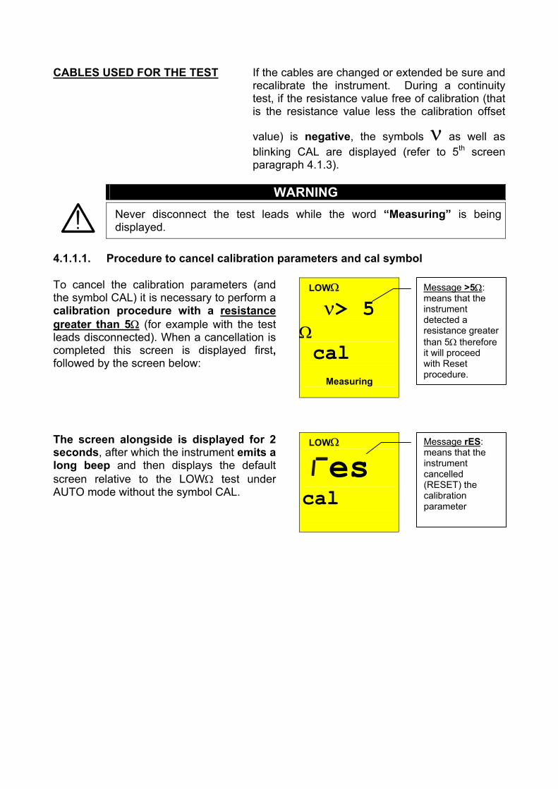
4.1.1.1. Procedure to cancel calibration parameters and cal symbol
LOWΩ ν> 5
Ω cal
Measuring
To cancel the calibration parameters (and the symbol CAL) it is necessary to perform a calibration procedure with a resistance greater than 5Ω (for example with the test leads disconnected). When a cancellation is completed this screen is displayed first, followed by the screen below:
Message >5Ω: means that the instrument detected a resistance greater than 5Ω therefore it will proceed with Reset procedure.
LOWΩ es cal
The screen alongside is displayed for 2 seconds, after which the instrument emits a long beep and then displays the default screen relative to the LOWΩ test under AUTO mode without the symbol CAL.
Message rES: means that the instrument cancelled (RESET) the calibration parameter
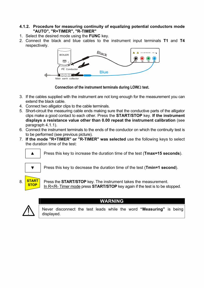
4.1.2. Procedure for measuring continuity of equalizing potential conductors mode "AUTO", "R+TIMER", "R-TIMER"
1. Select the desired mode using the FUNC key. 2. Connect the black and blue cables to the instrument input terminals T1 and T4
respectively.
B2 B3 B4B1
Connection of the instrument terminals during LOWΩ test. 3. If the cables supplied with the instrument are not long enough for the measurement you can
extend the black cable. 4. Connect two alligator clips to the cable terminals. 5. Short-circuit the measuring cable ends making sure that the conductive parts of the alligator
clips make a good contact to each other. Press the START/STOP key. If the instrument displays a resistance value other than 0.00 repeat the instrument calibration (see paragraph 4.1.1).
6. Connect the instrument terminals to the ends of the conductor on which the continuity test is to be performed (see previous picture).
7. If the mode "R+TIMER" or "R-TIMER" was selected use the following keys to select the duration time of the test:
Press this key to increase the duration time of the test (Tmax=15 seconds).
Press this key to decrease the duration time of the test (Tmin=1 second). 8. Press the START/STOP key. The instrument takes the measurement. START
STOP In R+/R- Timer mode press START/STOP key again if the test is to be stopped.
WARNING
Never disconnect the test leads while the word “Measuring” is being displayed.
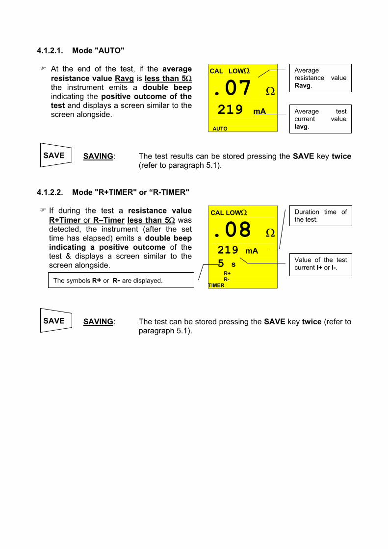
4.1.2.1. Mode "AUTO"
CAL LOWΩ .07 Ω 219 mA
AUTO
At the end of the test, if the average resistance value Ravg is less than 5Ωthe instrument emits a double beepindicating the positive outcome of the test and displays a screen similar to the screen alongside.
Average test current value Iavg.
Average resistance value Ravg.
SAVE
SAVING: The test results can be stored pressing the SAVE key twice (refer to paragraph 5.1).
4.1.2.2. Mode "R+TIMER" or “R-TIMER"
CAL LOWΩ .08 Ω 219 mA 5 s
R+ R-
TIMER
If during the test a resistance value R+Timer or R–Timer less than 5Ω was detected, the instrument (after the set time has elapsed) emits a double beepindicating a positive outcome of the test & displays a screen similar to the screen alongside.
Duration time of the test.
Value of the test current I+ or I-.
The symbols R+ or R- are displayed.
SAVE
SAVING: The test can be stored pressing the SAVE key twice (refer to paragraph 5.1).

4.1.3. Anomalous cases during "AUTO", "R+TIMER", "R-TIMER" tests
CAL LOWΩ 5.75 Ω 216 mA 5 s
AUTO
In case a value of Ravg or R+ or R-greater than or equal to 5Ω but less than 99.9Ω was detected, at the end of the test the instrument emits a long beep and displays a screen similar to the screen alongside.
Only in the case R+TIMER or R-TIMER was selected.
ATTENTION: value of Ravg greater than 5ΩAUTO mode.
CAL LOWΩ
> 99.9 Ω
- - - mA AUTO
In AUTO mode, if a Ravg or R+ or R-greater than 99.9Ω was detected, at the end of the test the instrument emits a long beep and displays the screen alongside.
99.9Ω is the maximum value that can be measured in the LOWΩ AUTO or R+ or R-mode.
ATTENTION: value of Ravg or R+ or R- is too high. AUTO mode.
CAL LOWΩ
> 99.9 Ω
- - - mA 4 s
R+ TIMER
In the case mode R+TIMER or R-TIMER was selected and a R+ or R-greater than 99.9Ω was detected, the instrument emits an intermittent beep during the test, a long beep at the end of the test and displays the screen alongside.
99.9Ω is the maximum value.
ATTENTION: value of R+ or R-is too high.
CAL LOWΩ
ν 0.00 Ω
219 mA
AUTO
In case that: RMEASURED-RCALIBRATION < 0Ω the instrument displays the screen alongside.
Blinking CAL.
ATTENTION: RMEASURED-RCALIBRATION< 0 AUTO mode.
SAVE SAVING: The tests can be stored pressing the SAVE key twice (refer
to paragraph 5.1).

CAL LOWΩ 13V VOL AG
If the terminal voltage is greater than 10V, the instrument does not perform the test and displays a screen similar to the screen alongside for 5 seconds. After which, the instrument displays the screen relative to the selected test mode LOWΩ under AUTO mode.
ATTENTION: the test was not completed because of voltage at the terminal ends.
SAVE THIS RESULT CANNOT BE SAVED.
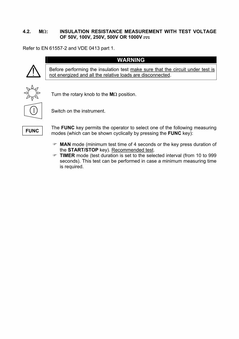
4.2. MΩ: INSULATION RESISTANCE MEASUREMENT WITH TEST VOLTAGE OF 50V, 100V, 250V, 500V OR 1000V
Refer to EN 61557-2 and VDE 0413 part 1.
WARNING
Before performing the insulation test make sure that the circuit under test is not energized and all the relative loads are disconnected.
Turn the rotary knob to the MΩ position.
Switch on the instrument.
The FUNC key permits the operator to select one of the following measuring modes (which can be shown cyclically by pressing the FUNC key): FUNC
MAN mode (minimum test time of 4 seconds or the key press duration of the START/STOP key). Recommended test.
TIMER mode (test duration is set to the selected interval (from 10 to 999 seconds). This test can be performed in case a minimum measuring time is required.

4.2.1. Procedure for measuring insulation resistance in any mode 1. Select the desired mode by means of the FUNC key. 2. Connect the black and blue cables to the instrument input terminals T1 and T4
respectively.
B2 B3 B4B1
M
Insulation between phase and earth in an electrical installation using untied cables.
3. If the cables supplied with the instrument are not long enough for the measurement you can
extend the blue cable. 4. Connect the instrument terminals to the object that is to be submitted to the insulation
test after disconnecting the circuit under test and all the relative loads (see previous picture).
5. By pressing the Un key select the test voltage suitable for the type of
test to be carried out (see table). The values to be selected are: • 50V (test on telecommunication system) • 100V • 500V • 250V • 1000V
Standard Brief description Test voltage Maximum limit value
CEI 64-8/6 Systems SELV or PELV
Systems up to 500V (Civil installations) Systems over 500V
250VDC 500VDC
1000VDC
> 0.250MΩ > 0.500MΩ > 1.0MΩ
CEI 64-8/4 Floor and wall insulation in civil installations Floor and wall insulation in systems over 500V
500VDC 1000VDC
> 50kΩ (if V<500V) > 100kΩ (if V>500V)
EN60439 Electrical panel boards 230/400V 500VDC > 230kΩ EN60204 Electrical equipment of machines 500VDC > 1MΩ
CEI 64-4 Floor insulation in medical rooms 500VDC <1MΩ (if the floor is at least 1 year old) <100MΩ (if the floor is at least 1year old)
Test voltage values and the relative maximum limit values for the most common kinds of test.
WARNING
If “Measuring” is displayed the instrument is performing the measurement. During this phase do not disconnect the test leads, as the circuit under test may remain charged at a dangerous voltage due to the parasite capacitance
Un DIST

of the installation. Independently of the working mode selected the instrument throws a resistance in the output terminals at the end of each test to discharge the parasite capacitance of the circuit.

4.2.1.1. Mode "MAN"
6. Press the START/STOP key. START STOP
The instrument performs the test lasting:
Minimum 4 seconds in case the key is pressed and released. Until the key is released for all the other cases.
RISO .00 MΩ 500 V 20 s
MAN
At the end of the test, in case the resistance value RISO detected results to be lower than RMAX (depending on the selected voltage see following table) and the test is performed at the selected rated voltage value, the instrument emits a double beepindicating the positive outcome of the test displays a screen similar to the screen alongside.
RISO insulation resistance value.
Rated voltage value selected for the test.
Manual mode.
Test duration. In this case the START/STOP key has been pressed for 20 seconds.
The values of measured resistance of isolation always must be confronted with the normative limits (see table) for being able to assert if the system is to norm.
SAVE
SAVING: The test can be stored pressing the SAVE key twice (refer to paragraph 5.1).

4.2.1.2. Mode "TIMER" 6. Use the following keys to set the duration time of the test:
Press this key to increase the duration time of the test (Tmax=999 seconds).
Press this key to decrease the duration time of the test (Tmin=10 seconds). 7. Press the START/STOP key. START
STOP The instrument completes the measurement when the set time has elapsed. 999 seconds → Maximum value of the test duration. 10 seconds → Minimum value of the test duration. Note: Pressing the START/STOP key again the test gets immediately interrupted.
RISO .07 MΩ 500 V 20 s
TIMER
At the end of the test, in case the resistance value RISO detected is lower than RMAX (depending on the selected voltage see following table) and the test is performed at the selected rated voltage value, the instrument emits a double beep indicating the positive outcome of the test displays one screen similar to the screen alongside.
Insulation resistance value RISO.
Rated voltage value selected for the Timer test.
SAVING: The test can be stored pressing the SAVE key twice (refer to paragraph 5.1).
Note: The maximum resistance value RMAX that can be measured in mode MΩ depends
on the rated voltage selected for the test. In particular:
Rated voltage selected for the test
RMAX = Maximum resistance value
50VDC 99.9MΩ 100VDC 199.9MΩ 250VDC 499MΩ 500VDC 999MΩ 1000VDC 1999MΩ
Timer mode.
Duration of the test.
SAVE

Maximum resistance values measurable under MΩ mode depend on the rated voltage selected.

4.2.2. Special cases which may occur during the tests "MAN" & "TIMER"
RISO > 999 MΩ 500 V 20 s
MAN
In case a value of RISO greater than RMAX was detected (depending on the selected voltage see following Notetable, the instrument emits a double beep at the end of the test indicating the positive outcome of the test and displays a screen similar to the screen alongside.
The symbol ">" means that the resistance value RISO is greater than RMAX
Maximum resistance value that can be measured (999Ω is displayed if a rated voltage of 500V was selected see table).
Selected mode MAN
Test duration
R ISO
ν0.01 MΩ 500 V 20 s
MAN
In case a test is performed at a voltage lower than the set rated voltage, at the end of the test the instrument emits a long beep and displays a screen similar to the screen alongside.
Selected mode MAN
ATTENTION: the test of resistance RISO was performed at a voltage value lower than the set rated voltage. Low insulation case. This case occurs under low insulation conditions or in the presence of capacitance on the installation.
SAVE
SAVING: The test can be stored pressing the SAVE key twice (refer to paragraph 5.1).
R ISO
ν 33V
VOL AG
If the terminal voltage is greater than 30V, the instrument does not perform the test, displays the screen alongside for 5 seconds after which, it shows the default screen relative to the RISO test under selected mode.
ATTENTION: the test was not carried out. Check that the circuit is not energized.
SAVE
THIS RESULT CANNOT BE SAVED.

4.3. : PHASE SEQUENCE INDICATOR
Turn the rotary knob to the position.
Switch on the instrument.
WARNING
Never disconnect the test leads while the word “Measuring” is being displayed.

4.3.1. Mode " " 1. Connect the three black, red and green connectors of the untied cables in the corresponding
input terminals of the instrument T1, T2, T3 and the alligator clips to the free ends of the cables.
B2 B3 B4B1
L1L2L3N
Instrument connection for phase sequence indication L1=black cable, L2=blue cable, L3=green cable
2. Connect the alligator clips to the three phases of the system under test. The instrument displays the following screen (before pushing START/STOP key):
386 V
388V 388V
Voltage value between Phase1 and Phase2.
Voltage value between Phase3 and Phase1.
Voltage value between Phase2 and Phase3.
4. Press the START/STOP key to start the measurement of phase sequence, one of the following screen will be displayed:
START STOP
123
At the end of the test the instrument displays the values alongside in case of correct phase sequence, which means the black cable is connected to the phase1=L1, the blue cable to the phase2=L2 and green cable to the phase3=L3.
ν 213
At the end of the test the instrument displays the values alongside in case of wrong phase sequence.
WARNING
Message "213": indicates that the phase sequence is wrong.
Message "123": indicates that the phase sequence is correct.

Never disconnect the test leads while the word “Measuring” is being displayed.
SAVE
SAVING: The tests can be stored pressing the SAVE key twice (refer to paragraph 5.1).

4.3.2. Anomalous cases which may occur during phase sequence tests
L
VOL AG
In the case that every delta voltage is lower than 100V, the instrument doesnot perform the test and displays the screen alongside.
Message “Lo VOL tAG”: the instrument has at least one low voltage. The instrument does not perform the test.
ν A
l1
If the voltage present at the T1 input is too low, when START/STOP is pressedthe instrument displays the message alongside.
Message “Att no L1”: voltage of phase 1 is too low
ν A
l2
If the voltage present at the T2 input is too low, when START/STOP is pressedthe instrument displays the message alongside.
Message “Att no L2”: voltage of phase 2 is too low
ν A
l3
If the voltage present at the T3 input is too low, when START/STOP is pressedthe instrument displays the message alongside.
Message “Att no L3”: voltage of phase 3 is too low
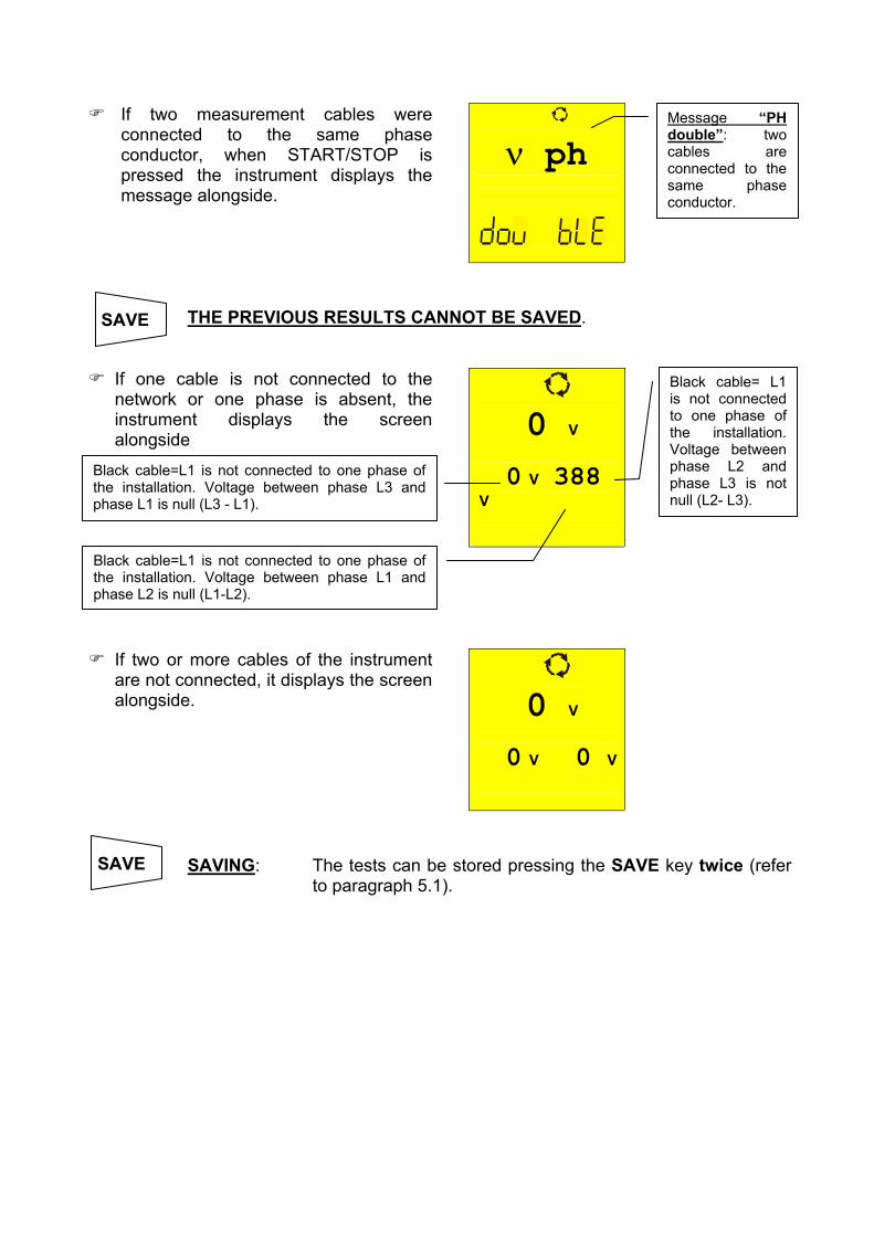
ν ph
If two measurement cables were connected to the same phase conductor, when START/STOP is pressed the instrument displays the message alongside.
Message “PH double”: two cables are connected to the same phase conductor.
SAVE THE PREVIOUS RESULTS CANNOT BE SAVED.
0 V
0 V 388 V
If one cable is not connected to the network or one phase is absent, the instrument displays the screen alongside
Black cable= L1 is not connected to one phase of the installation. Voltage between phase L2 and phase L3 is not null (L2- L3).
Black cable=L1 is not connected to one phase of the installation. Voltage between phase L1 and phase L2 is null (L1-L2).
Black cable=L1 is not connected to one phase of the installation. Voltage between phase L3 and phase L1 is null (L3 - L1).
0 V
0 V 0 V
If two or more cables of the instrument are not connected, it displays the screen alongside.
SAVE
SAVING: The tests can be stored pressing the SAVE key twice (refer to paragraph 5.1).

4.4. EARTH ρ: EARTH RESISTANCE AND RESISTIVITY MEASUREMENT
Turn the rotary knob to the EARTH ρ position.
Switch on the instrument.
The FUNC key permits to select one of the following measuring modes (which can be shown cyclically when pressing the key): FUNC
Mode “2P” (the instrument measures earth resistance between 2 points). Mode “3P” (the instrument measures earth resistance using two auxiliary
earth rods). Mode “ρ“ (the instrument measures earth resistivity).
The resistance is measured with a 4-cable voltamperometric method, so the value measured is not dependant on the utilized cables. For this reason this method doesn’t need any cable calibration. If the cables aren’t long enough, lengthen them or utilize cables longer than the standard ones.
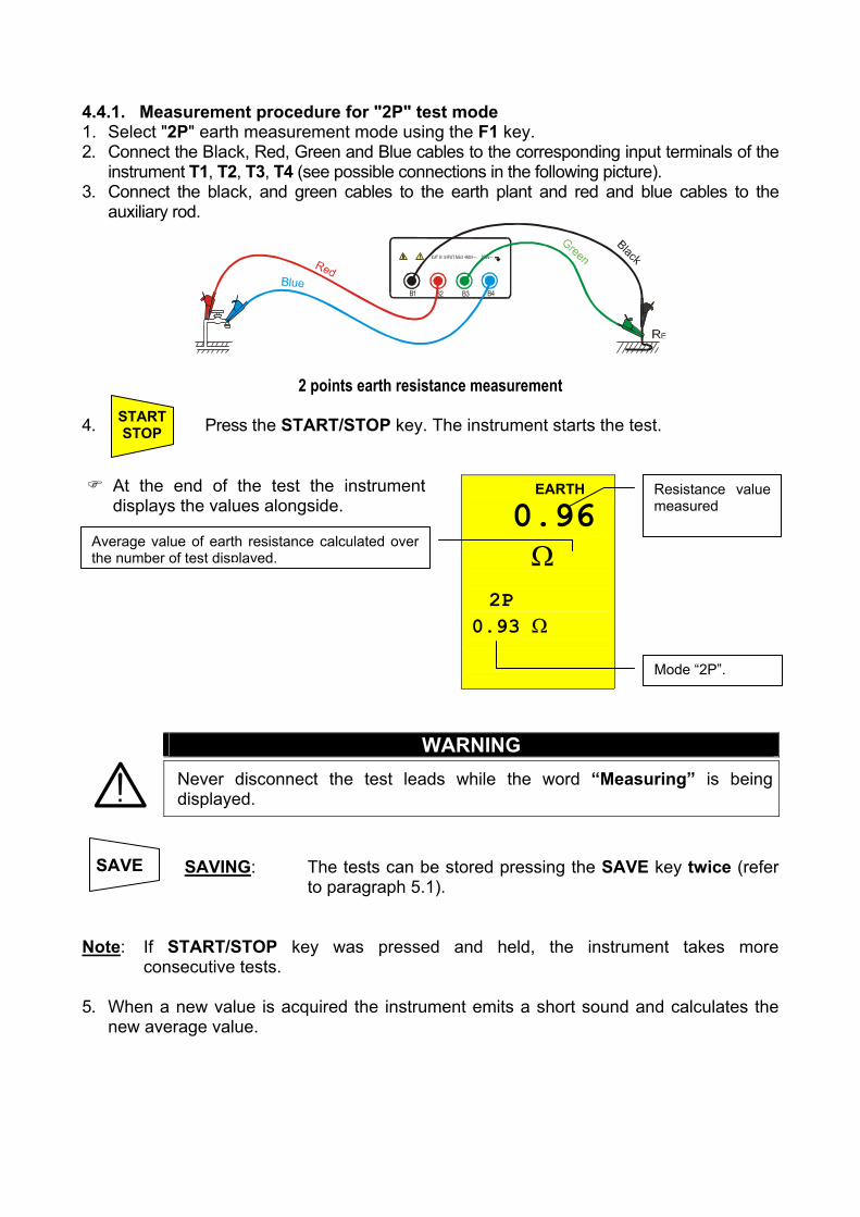
4.4.1. Measurement procedure for "2P" test mode 1. Select "2P" earth measurement mode using the F1 key. 2. Connect the Black, Red, Green and Blue cables to the corresponding input terminals of the
instrument T1, T2, T3, T4 (see possible connections in the following picture). 3. Connect the black, and green cables to the earth plant and red and blue cables to the
auxiliary rod.
B2 B3 B4B1
2 points earth resistance measurement 4. Press the START/STOP key. The instrument starts the test. START
STOP
EARTH 0.96 Ω
2P 0.93 Ω
At the end of the test the instrument displays the values alongside.
Average value of earth resistance calculated over the number of test displayed.
Resistance value measured
Mode “2P”.
WARNING
Never disconnect the test leads while the word “Measuring” is being displayed.
SAVE
SAVING: The tests can be stored pressing the SAVE key twice (refer to paragraph 5.1).
Note: If START/STOP key was pressed and held, the instrument takes more
consecutive tests. 5. When a new value is acquired the instrument emits a short sound and calculates the
new average value.
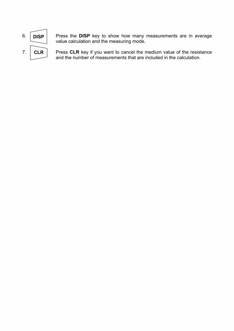
6. Press the DISP key to show how many measurements are in average
value calculation and the measuring mode. DISP
7. Press CLR key if you want to cancel the medium value of the resistance
and the number of measurements that are included in the calculation. CLR
When the environmental conditions preclude the “3P” measurement mode, as for example in a city center. In TT plants it is possible to measure the earth resistance with the simplified “2P” method that gives a higher value than the “3P” mode does. An auxiliary rod is necessary; it must have an insignificant earth resistance and must be independent of the earth plant under test. In the picture above, a water tube is used as the auxiliary rod. But, any metallic object fixed to the ground could replace it. Example: if the operator takes three consecutive measurements, the instrument displays
1st measurement: main display = measured resistance value (Ex: 0.90Ω) secondary display on the left-hand side = 001 (no. of measurements = 1 means that 1 earth measurement has been taken) secondary display = average of the measurements taken (in case just one measurement has been taken the medium value is equal to the measured value, in this case 0.90Ω)
2nd measurement: main display = measured resistance value (Ex: 0.96Ω) secondary display = average of the measurements taken ((Val1+Val2)/no. of measurements = (0.90+0.96)/2 = 0.93Ω)
3rd measurement: main display = measured resistance value (Ex: 0.93Ω) secondary display = average of the measurements taken ((Val1+Val2)/no. of measurements = (0.90+0.96+0.93)/3 = 0.93Ω)
Note: Any test with a result over 1999Ω is not inserted in the calculation of medium
value. Example: 1st measurement:
main display: 1.07Ω secondary display: 1.07Ω
2nd measurement main display: 4.15Ω secondary display: 2.61Ω
3rd measurement (not inserted in the medium value) main display: >1999Ω secondary display: 2.61Ω

4.4.1.1. Earth resistance measurement from a socket On TT installations it’s possible to take an earth measurement with a simplified method that gives an excess value (therefore safer), using the NEUTRAL of the national Energy Board taken directly from a socket as an auxiliary rod; if also the earth connection is available, naturally the measurement can be taken on the socket directly, between NEUTRAL and EARTH. Although this test is not provided for by CEI 64.8 at present, it gives a value which many 3-wires comparison tests proved to be revealing for earth resistance.
B2 B3 B4B1
Earth measurement with simplified method on panel board
WARNING
If you want to take the measurement using the neutral and the earth of a standard wall socket, you may accidentally connect to the hot leg. In this case the display will show the voltage, the symbol (wrong insertion) and won’t take any measurement even if START/STOP is pressed.
WARNING
Never disconnect the test leads while the word “Measuring” is being displayed.

4.4.2. Measurement procedure for "3P" test mode The measurement is taken according to what is prescribed for CEI 64.8, IEC 781, VDE 0413, EN61557-5. 1. Select "3P" earth measurement mode using the F1 key. 2. Connect the Black, Red, Green and Blue cables to the corresponding input terminals of the
instrument T1, T2, T3, T4 (see possible connections in the following picture). 3. Connect the black, and green cables to the earth plant and red and blue cables to the
auxiliary rods.
B2 B3 B4B1
3 points earth resistance measurement Measuring small earth plants, current probe must be positioned a distance from the earth equipment outline corresponding to five times the diagonal of the area of the earth equipment under test, measuring big earth plants this distance could be reduced up to one times the diagonal. 4. Press the START/STOP key. The instrument starts the test.
EARTH 0.96 Ω
2P 0.93 Ω
At the end of the test the instrument displays the values alongside.
WARNING
The display of “Measuring” means that the instrument is measuring. During this phase never disconnect test leads.
Average value of earth resistance calculated over the number of test displayed.
Resistance value measured
Mode “2P”.
START STOP

SAVE
SAVING: The tests can be stored pressing the SAVE key twice (refer to paragraph 5.1).

Note: If the START/STOP key was pressed and held, the instrument takes more consecutive tests.
5. When a new value is acquired the instrument emits a short sound and calculates the
new average value. 6. Press DISP key to show how many measurements are in average value
calculation and the measuring mode. DISP
7. Press CLR key if you want to cancel the medium value of the resistance
and the number of measurements which are included in the calculation. CLR
Example: if the operator takes three consecutive measurements, the instrument displays
1st measurement: main display = measured resistance value (Ex: 0.90Ω) secondary display on the left-hand side = 001 (no. of measurements = 1 means that 1 earth measurement has been taken) secondary display = average of the measurements taken (in case just one measurement has been taken the medium value is equal to the measured value, in this case 0.90Ω)
2nd measurement: main display = measured resistance value (Ex: 0.96Ω) secondary display = average of the measurements taken ((Val1+Val2)/no. of measurements = (0.90+0.96)/2 = 0.93Ω)
3rd measurement: main display = measured resistance value (Ex: 0.93Ω) secondary display = average of the measurements taken ((Val1+Val2)/no. of measurements = (0.90+0.96+0.93)/3 = 0.93Ω)
Note: Any test with result over 1999Ω is not inserted in the calculation of medium value. Example: 1st measurement:
main display: 1,07Ω secondary display: 1,07Ω
2nd measurement main display: 4,15Ω secondary display: 2,61Ω
3rd measurement (not inserted in the medium value) main display: >1999Ω secondary display: 2,61Ω
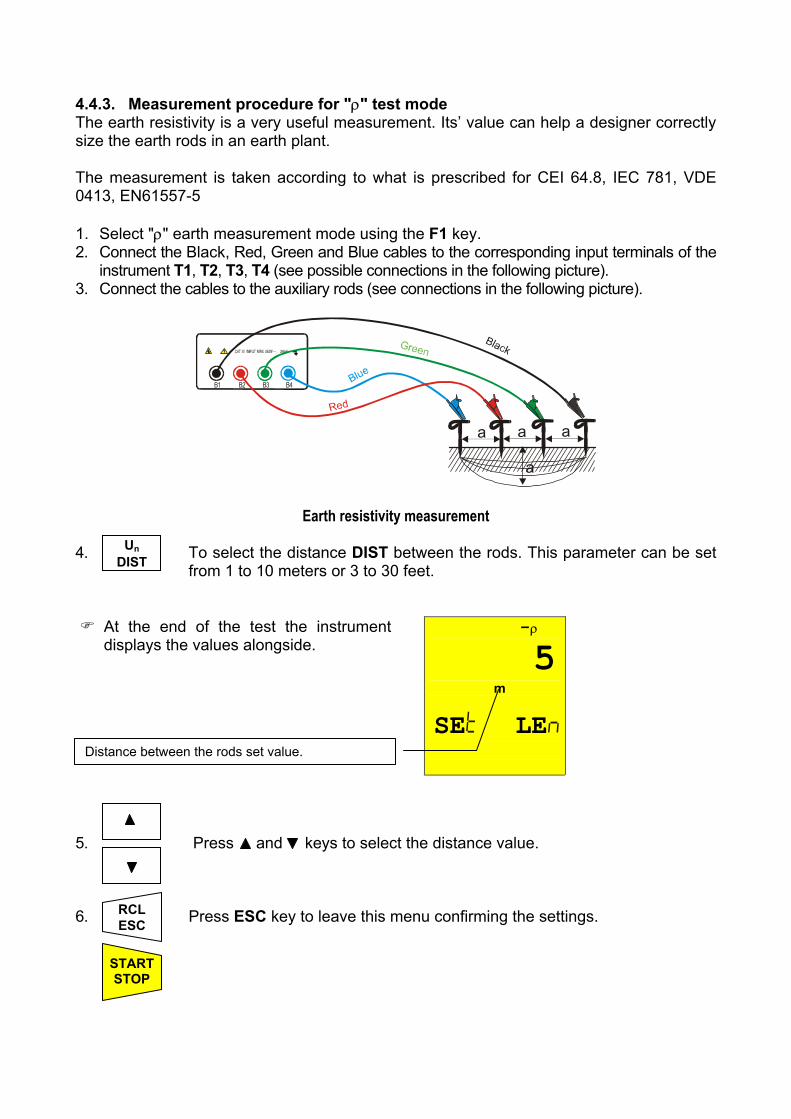
4.4.3. Measurement procedure for "ρ" test mode The earth resistivity is a very useful measurement. Its’ value can help a designer correctly size the earth rods in an earth plant. The measurement is taken according to what is prescribed for CEI 64.8, IEC 781, VDE 0413, EN61557-5 1. Select "ρ" earth measurement mode using the F1 key. 2. Connect the Black, Red, Green and Blue cables to the corresponding input terminals of the
instrument T1, T2, T3, T4 (see possible connections in the following picture). 3. Connect the cables to the auxiliary rods (see connections in the following picture).
B2 B3 B4B1
a
a
aa
Earth resistivity measurement 4. To select the distance DIST between the rods. This parameter can be set
from 1 to 10 meters or 3 to 30 feet.
Un DIST
-ρ 5
m SE LE
At the end of the test the instrument displays the values alongside.
Distance between the rods set value.
5. Press and keys to select the distance value.
6. Press ESC key to leave this menu confirming the settings. RCL
ESC
START STOP

7. Press the START/STOP key. The instrument starts the test.
ρ 36.5Ωm
2 0.93 Ω
At the end of the test the instrument displays the values alongside.
Earth resistivity value
WARNING
Never disconnect the test leads while the word “Measuring” is being displayed.
SAVE
SAVING: The tests can be stored by pressing the SAVE key twice (refer to paragraph 5.1).
Note: If START/STOP key is pressed & held, the instrument takes more consecutive
tests. 8. When a new value is acquired the instrument emits a short sound and calculates the
new average value. 9. Press DISP key to show how many measurements are in average value
calculation and the measuring mode. DISP
10. Press CLR key if you want to cancel the medium value of the resistance
and the no. of measurements which are included in the calculation. CLR
Note: Any test with result over 1999Ω is not inserted in the calculation of medium value. Example: 1st measurement (D=1):
main display: 6,6Ωm secondary display: 6,6Ωm
2nd measurement (D=1):

main display: 4,15Ω secondary display: 2,61Ω
3rd measurement (not inserted in the medium value) main display: >1999Ω secondary display: 2,61Ω
4.5. ANOMALOUS CASES WHICH MAY OCCUR DURING EARTH ρ TESTS
- - -
- - - c
If the amperometric circuit is interrupted, when pressing START/STOP the instrument can’t read the minimum current, therefore a screen similar to the one beside appears. Make sure that the terminals are connected correctly and that the amperometric rod (blue conductor) has not been driven into non-conductive ground. If necessary, pour water around the rod.
rC indicates a high resistance value.
SAVE THE PREVIOUS RESULTS CANNOT BE SAVED.
31 V VOL AG
If the instrument measures an interfering voltage greater than 30V on the amperometric circuit, it doesn’t perform the test and a screen similar to the one beside appears.
Voltage value on the amperometric circuit
SAVE THE PREVIOUS RESULT CANNOT BE SAVED.

>1999 Ω - - - - - -
If the resistance measured is greater than the full scale of the instrument, after pressing START/STOP the instrument performs the test and a screen similar to the one beside appears.
1999Ω is the full scale of the instrument.
> 1999 Ω - - - - - -
If the resistivity measurement is greater than the following value 1999x6.28x(distance between the rods selected), after pressing START/STOPthe instrument performs the test and a screen similar to the one beside appears.
1999Ω is the full scale of the instrument.
SAVE
SAVING: The tests can be stored pressing the SAVE key twice (refer to paragraph 5.1).

5. HOW TO SAVE, RECALL AND CLEAR DATA STORED IN MEMORY 5.1. SAVE: "SAVE" KEY If the results relative to the tests performed are to be stored you can proceed as follows: 1. Press the SAVE key once. SAVE
MEM 3
PLA 02
If the memory of the instrument is not empty it displays the screen alongside.
Number of the memory location in which the measurement results will be stored.
Value of the parameter PLA related to the measurement to be saved.
2. Use the & keys to increase or decrease the value of the PLA
(Place) parameter to be related to the measurement that is to be saved. This parameter helps the operator to classify the tests performed.
Example: If the tests are to be carried out in a building, the operator
can associate the measurements performed in a room with a given value of the parameter PLA. In this way different values of the parameter PLA will correspond to different rooms.
3. Press the SAVE key again, the instrument emits two beeps,
confirming that the test results have been stored. SAVE
RCL ESC
Press RCL/ESC key at any time to leave the memory menu and go back to the measurement selected.
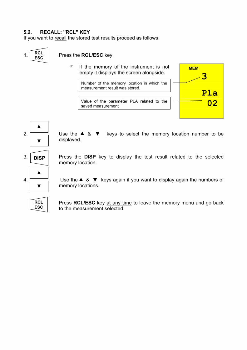
5.2. RECALL: "RCL" KEY If you want to recall the stored test results proceed as follows: 1. Press the RCL/ESC key. RCL
ESC MEM 3
Pla 02
If the memory of the instrument is not empty it displays the screen alongside.
Number of the memory location in which the measurement result was stored.
Value of the parameter PLA related to the saved measurement
2. Use the & keys to select the memory location number to be
displayed.
3. Press the DISP key to display the test result related to the selected
memory location. DISP
4. Use the & keys again if you want to display again the numbers of
memory locations.
RCL ESC
Press RCL/ESC key at any time to leave the memory menu and go back to the measurement selected.
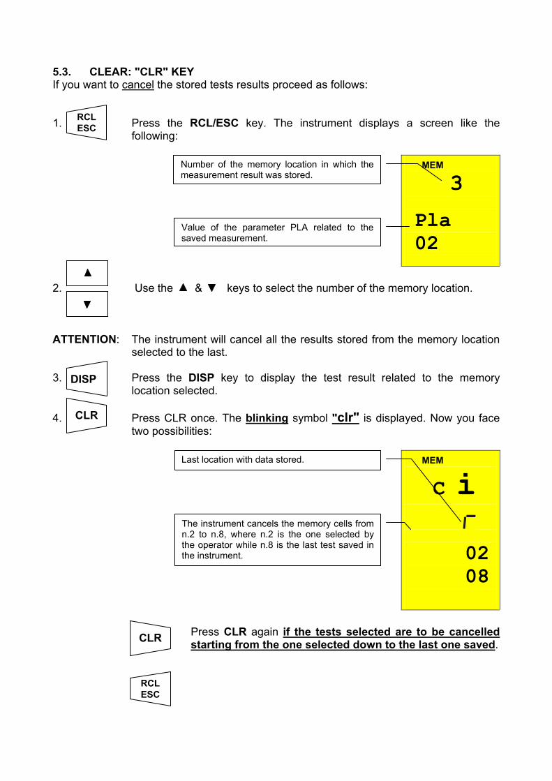
5.3. CLEAR: "CLR" KEY If you want to cancel the stored tests results proceed as follows: 1. Press the RCL/ESC key. The instrument displays a screen like the
following:
MEM 3
Pla 02
2. Use the & keys to select the number of the memory location. ATTENTION: The instrument will cancel all the results stored from the memory location
selected to the last. 3. Press the DISP key to display the test result related to the memory
location selected. 4. Press CLR once. The blinking symbol "clr" is displayed. Now you face
two possibilities:
MEM C i
02 08
Number of the memory location in which the measurement result was stored.
Value of the parameter PLA related to the saved measurement.
DISP
Last location with data stored.
The instrument cancels the memory cells from n.2 to n.8, where n.2 is the one selected by the operator while n.8 is the last test saved in the instrument.
CLR
RCL ESC
CLR Press CLR again if the tests selected are to be cancelled starting from the one selected down to the last one saved.
RCL ESC
Press RCL/ESC to nullify the clearing phase. The blinking symbol "clr" disappears.
RCL ESC
Press RCL/ESC key at any time to leave the memory menu and go back to the measurement selected.

6. RESET OF THE INSTRUMENT AND DEFAULT PARAMETERS BEFORE OF A RESET PROCEDURE DOWNLOAD THE STORED TESTS ON A PC 6.1. RESET PROCEDURE 1. Press the DISP, CLR, RCL keys and then ON/OFF key. 2.
es
The screen alongside is displayed for 5 seconds, after which the instrument emits a beep and then displays the screen relative to the function selected with the rotary switch.
ATTENTION: the reset procedure will cancel all the stored tests and it will set the
default parameters in the instrument. 6.2. DEFAULT PARAMETERS After a RESET the default parameters set on the instrument are:
Function Parameter RESET default parameter
Mode AUTO Calibration Offset 0 LOWΩ
Mode R+/R- TIMER TIMER is set at 1s
Mode MAN Test voltage 500V RISO Mode TIMER TIMER is set at 60s
EARTH ρ Parameter DIST DIST = 1
Parameter PLA P = 1 Memory Memory state 0
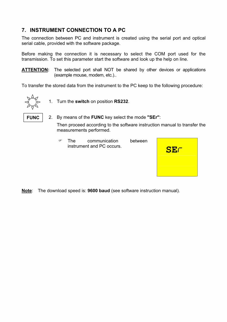
7. INSTRUMENT CONNECTION TO A PC The connection between PC and instrument is created using the serial port and optical serial cable, provided with the software package. Before making the connection it is necessary to select the COM port used for the transmission. To set this parameter start the software and look up the help on line. ATTENTION: The selected port shall NOT be shared by other devices or applications
(example mouse, modem, etc.).. To transfer the stored data from the instrument to the PC keep to the following procedure:
1. Turn the switch on position RS232.
FUNC 2. By means of the FUNC key select the mode "SEr": Then proceed according to the software instruction manual to transfer the measurements performed.
SE
The communication between instrument and PC occurs.
Note: The download speed is: 9600 baud (see software instruction manual).

8. MAINTENANCE 8.1. GENERAL 1. The instrument you have purchased is a precision instrument. Strictly follow the
instructions for use and storage reported in this manual to avoid any possible damage or danger during use.
2. Do not use this tester under unfavorable conditions of high temperature or humidity. Do not expose to direct sunlight.
3. Be sure to turn off the tester after use. If the instrument is not to be used for a long period you are recommended to remove the batteries to avoid acid leakage that may damage the internal circuits of the instrument.
8.2. BATTERY REPLACEMENT When the symbol is displayed batteries are to be replaced.
WARNING
Only skilled technicians can perform this operation. Before replacing batteries make sure that all test leads have been disconnected from input terminals. The instrument will retain the data stored even though the batteries are not installed.
1. Switch OFF the instrument. 2. Remove all the test leads from the input terminals. 3. Unscrew the fixing screw from the battery compartment cover and remove it. 4. Remove all batteries replacing them with 6 new ones. 5. Fix the screw on the battery compartment cover. 8.3. INSTRUMENT CLEANING Use a soft dry cloth to clean the instrument. Never use wet cloths, solvents, water, etc.

9. TECHNICAL SPECIFICATIONS 9.1. TECHNICAL FEATURES Accuracy is indicated as [% of reading + number of digits]. It refers to the atmospheric conditions listed in paragraph 9.2.1. - Continuity (LOWΩ)
Test mode Measuring range (Ω) Resolution (Ω) Accuracy 0,01 – 19,99 0,01 AUTO, R+TIMER, R-TIMER 20,0 – 99,9 0,1 ±(2% rdg + 2 dgt)
Test current >200mA DC up to 5Ω (include the resistance of the calibration) Test current resolution 1mA Open circuit Test Voltage 6V < V0 < 12V - Insulation resistance (RISO)
Test voltage (V) Measuring range (Ω) Resolution (Ω) Accuracy 0,01 - 19,99 0,01 20,0 - 49,9 0,1 ±(2% rdg + 2 dgt) 50 50,0 - 99,9 0,1 ±(5% rdg + 2 dgt)
0,01 - 19,99 0,01 20,0 - 99,9 0,1 ±(2% rdg + 2 dgt) 100
100,0 - 199,9 0,1 ±(5% rdg + 2 dgt) 0,01 - 19,99 0,01 20,0 - 199,9 0,1
200 - 249 1 ±(2% rdg + 2 dgt) 250
250 - 499 1 ±(5% rdg + 2 dgt) 0,01 - 19,99 0,01 20,0 - 199,9 0,1
200 - 499 1 ±(2% rdg + 2 dgt) 500
500 - 999 1 ±(5% rdg + 2 dgt) 0,01 - 19,99 0,01 20,0 - 199,9 0,1
200 - 999 1 ±(2% rdg + 2 dgt) 1000
1000 - 1999 1 ±(5% rdg + 2 dgt)
Automatic selection of the measuring range Open circuit voltage Rated voltage test –0% +10% Short circuit current <6,0mA with 500V set Rated measuring current >2,2mA with 500V on 230kΩ 1mA a 1KΩ x VNOM (≠ 500 V) - AC voltage
Measuring range (V) Resolution (V) Accuracy 0 ÷ 460 1 ±(3% rdg + 2 dgt)
- Earth resistance measurement with voltamperometric method
Measuring range (Ω) Resolution (Ω) Accuracy 0,01 ÷ 19,99 0,01 20,0 ÷ 199,9 0,1 200 ÷ 1999 1
±(5% rdg + 3 dgt)
Test current <10mA 77,5Hz Open load test voltage <20V RMS


- Earth resistivity ρ measurement
Measuring range (Ω) Resolution (Ωm) Accuracy 0.06 ÷ 19,99 Ωm 0,01 Ωm 20.0 ÷ 199.9 Ωm 0.1 Ωm 200 ÷ 1999 Ωm 1 Ωm
2,00 ÷ 19,99 kΩm 0.01 kΩm 20.0 ÷ 125,5 kΩm (*) 0.1 kΩm
±(5% rdg + 3 dgt)
(*) with D = 10m Test current <10mA 77,5Hz Open load test voltage <20V RMS
9.1.1. Safety standards The instrument complies with: EN 61010-1 + A2(1997) Product norms: IEC61557-1, -2, -3, -4, -5, -6 Insulation: Class 2, double insulation Pollution level: 2 Inside use; max height: 2000m Overvoltage category: CAT III 460V∼ T1-T2-T3-T4 / 265V∼ to earth 9.1.2. General specifications Mechanical features Dimensions: 222(L) x 165(La) x 105(H)mm Weight (batteries included): approx. 1200g Power supply Battery type: 6 batteries 1.5 V – LR6 – AA – AM3 – MN 1500 Low battery indication: The symbol is displayed when the battery
voltage is too low. Battery life: About 40 hours in stand-by or 500 LowΩ tests or 250 RISO tests 500V/500kΩ or 1000 Loop, phase sequence tests 300 Earth or ρ tests. Display: LCD custom 65mmx65mm Memory: 350 tests Serial interface: opto-isolated RS232 to download stored data to a
PC.

9.2. ENVIRONMENT 9.2.1. Environmental working conditions Reference temperature: 23° ± 5°C Working temperature: 0°C ÷ 40 °C Relative humidity allowed: <80% Storage temperature: -10 ÷ 60 °C Storage humidity: <80% 9.2.2. EMC This instrument was designed in compliance with the EMC standards in force and its compatibility has been tested for EN61326-1 (1998) + A1 (1999). This instrument conforms to European directive for CE standards. This instrument complies with the requirements of the European Low Voltage Directives 73/23/CEE and EMC 89/336/CEE, amended with 93/68/CEE. 9.3. ACCESSORIES The accessories provided with the instrument depend on the model purchased according to the following table. The accessory is named standard when it is sold together with the instrument in a single package. Standard accessories
Description Code Description Code
Set with 4 cables, 4 alligator clips and 2 test leads
MTL-MT1 Software and Manual www.amprobe.com
Serial cable C2001 Bag with 4 cables (banana-alligator clip) and 4 rods GP2-CON Carrying case CC-MT1
Optional accessories Set for carrying belt CN0050

10. SERVICE 10.1. WARRANTY CONDITIONS Congratulations! Your new instrument has been quality crafted according to quality standards and contains quality components and workmanship. It has been inspected for proper operation of all of its functions and tested by qualified factory technicians according to the long-established standards of our company. Your instrument has a limited warranty against defective materials and/or workmanship for 1 year from the date of purchase provided that, in the opinion of the factory, the instrument has not been tampered with or taken apart. Should your instrument fail due to defective materials, and/or workmanship during this 1 year period, a no charge repair or replacement will be made to the original purchaser. Please have your dated bill of sale, which must identify the instrument model number and serial number and call the number listed below:
Repair Department ATP – Amprobe, TIF, Promax Miramar, FL
Phone: 954-499-5400 800-327-5060
Fax: 954-499-5454 Website: www.amprobe.com
Please obtain an RMA number before returning product for repair. Outside the U.S.A. the local representative will assist you. Above limited warranty covers repair and replacement of instrument only and no other obligation is stated or implied.
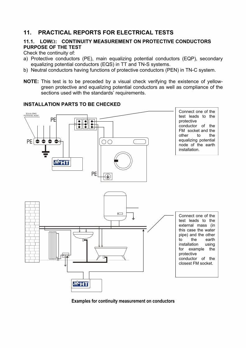
11. PRACTICAL REPORTS FOR ELECTRICAL TESTS 11.1. LOWΩ: CONTINUITY MEASUREMENT ON PROTECTIVE CONDUCTORS PURPOSE OF THE TEST Check the continuity of: a) Protective conductors (PE), main equalizing potential conductors (EQP), secondary
equalizing potential conductors (EQS) in TT and TN-S systems. b) Neutral conductors having functions of protective conductors (PEN) in TN-C system. NOTE: This test is to be preceded by a visual check verifying the existence of yellow-
green protective and equalizing potential conductors as well as compliance of the sections used with the standards’ requirements.
INSTALLATION PARTS TO BE CHECKED
Connect one of the test leads to the protective conductor of the FM socket and the other to the equalizing potential node of the earth installation.
Connect one of the test leads to the external mass (in this case the water pipe) and the other to the earth installation using for example the protective conductor of the closest FM socket.
Examples for continuity measurement on conductors

Check the continuity among: a) Earth poles of all the plugs and earth collector or node. b) Earth terminals of class I instruments (Boiler etc.) and earth collector or node. c) Main external masses (water, gas pipes etc.) and earth collector or node. d) Auxiliary external masses to the earth terminal. ALLOWABLE VALUES The standards CEI 64-8/6 do not give any indication of the maximum resistance values in order to be able to declare a positive outcome of a continuity test. The standard CEI 64-8/6 simply requires that the instrument in use warns the operator if the test was not carried out with a current of at least 0.2 A and an open circuit voltage ranging from 4 V to 24 V. The resistance values can be calculated according to the sections and lengths of the conductors under test. If the instrument detects values of some resistance the test can be considered as passed. 11.2. INSULATION RESISTANCE MEASUREMENT OF THE ELECTRICAL
INSTALLATIONS (250VDC, 500VDC, 1000VDC) PURPOSE OF THE TEST Check that the insulation resistance of the installation complies with the requirements of standards CEI 64-8/6. NOTE: This test is to be performed on an open circuit with all loads disconnected. INSTALLATION PARTS TO BE CHECKED a) Between each active conductor and the earth (the neutral conductor is considered an
active conductor except in the case of TN-C systems where it is considered part of the earth (PEN). During this measurement all active conductors can be connected to each other, in case the measurement result does not fall within the standard limits the test is to be repeated for each single conductor.
b) Among active conductors. The standard CEI 64-8/6 recommends checking the insulation among the active conductors when this is possible (ATTENTION).
ALLOWABLE VALUES The values of test voltage and minimum insulation resistance are reported in the following table (CEI64-8/6 Tab. 61A):
Rated circuit voltage (V) Test voltage (V) Insulation resistance (MΩ)SELV and PELV* 250 ≥0.250 Up to 500 V included, except for the above circuits. 500 ≥0.500
Over 500 V 1000 ≥1.000 * In the new standards the terms SELV and PELV replace the old definitions "safety low
voltage" or "functional".

Test voltage values and relative limit values for the most common kinds of test.

11.3. MEASUREMENT OF FLOOR INSULATION RESISTANCE IN MEDICAL ROOMS PURPOSE OF THE TEST Check that the floor is made of material whose insulation resistance complies with the requirements of the standards CEI 64-4 (3.05.03). INSTALLATION PARTS TO BE CHECKED The test shall be performed between: a) Two electrodes whose distance to each other shall be one meter. b) One electrode on the floor and the equalizing potential node.
EQUALIZING POTENTIAL NODE
TEST LEADS
T
.
Connect one test lead of the instrumentto the equalising potential node and theother to one of the electrodes placedon the floor at a distance higher thanone meter away from earthed objects
Test a):
T
.
Connect the instrument test leads tothe electrodes placed on the floor ata reciprocal distance of one meter
Test b):
Measurements of floor insulation resistance in medical rooms The electrodes shall consist of a plate having a surface of 20 cm2, weight equal to approx. 1 Kg (2.2 lb), and a moisture absorbent paper (or thin cotton cloth) with the same surface placed between the metal plate and the floor. The insulation resistance is represented, both for the measurements indicated in "a" and for the measurements indicated in "b", by the average of 5 or more tests performed in different positions at a distance greater than 1 m away from earthed objects. ALLOWABLE VALUES The maximum values of the calculated resistance are the following: - 1 MΩ for measurements performed on a new floor. - 100 MΩ for the periodic tests performed after the first year from the floor construction
and for the periodic checks every 4 years. All the values shall be registered on a protocol of the initial tests (64-4 5.1.02).
11.4. CHECK OF THE CIRCUIT SEPARATION PURPOSE OF THE TEST The test, to be performed in case the protection is realized through separation (64-8/6 612.4, SELV or PELV or electrical separation), shall check that the insulation resistance measured according to the indications below (depending on the separation type) complies with the limits reported in the table relative to the insulation measurements. INSTALLATION PARTS TO BE CHECKED • SELV system (Safety Extra Low Voltage):
Measure the resistance between the active parts of the circuit under test (separate) and the active parts of the other circuits.
Measure the resistance between the active parts of the circuit under test (separate) and the earth.
The resistance shall not be lower than 0.25MΩ with a test voltage of 250VDC. • PELV system (Protective Extra Low Voltage):
Measure the resistance between the active parts of the circuit under test (separate) and the active parts of the other circuits.
The resistance shall not be lower than 0.25MΩ with a test voltage of 250VDC. • Electrical separation:
Measure the resistance between the active parts of the circuit under test (separate) and the active parts of the other circuits.
Measure the resistance between the active parts of the circuit under test (separate) and the earth.
The resistance shall not be lower than 0.5MΩ with a test voltage of 500VDC and 1MΩ with a test voltage of 1000VDC. ALLOWABLE VALUES The test result is positive when the insulation resistance indicates values greater or equal to those indicated in the table reported in the section relative to insulation tests. Please note that: A SELV system is a system of category zero or very low safety voltage featured by: independent source (ex. batteries, small generator) or safety (ex. safety transformer) power supply, protection separation to other electrical systems (double or reinforced insulation or a metal screen connected to the earth) and no earthed points (insulated from the earth). A PELV system is a system of category zero or very low safety voltage featured by: independent source (ex. batteries, small generator) or safety (ex. safety transformer) power supply, protection separation to other electrical systems (double or reinforced insulation or a metal screen connected to the earth) and there are earthed points (not insulated from the earth).

A system with Electrical separation is featured by: insulation transformer or autonomous source with equivalent features (ex. generator) power supply, protection separation to other electrical systems (insulation not lower than that of the insulation transformer) and protection separation to the earth (insulation not lower than that of the insulation.

EXAMPLE OF CHECKING THE SEPARATION AMONG ELECTRICAL CIRCUITS
...and among those others circuits
…and Earth installation
Between active parts ofthe separated circuit...
Insulation or safety transformer makingthe separation among the circuits.
EQUALIZING POTENTIAL NODE
TEST AMONG THE ACTIVE PARTSConnect a test lead of the instrumentto one of the two conductors of theseparate circuit and the other to one ofthe conductors of a no separate circuit.
TEST BETWEEN ACTIVEPARTS AND THE EARTHConnect a test lead of theinstrument to one of the twoconductors of the separatecircuit and the other to theequalising potential node.This test is to be effectedonly for SELV circuits orwith electrical separation.
Measurement of separation among the installation circuits

11.5. EARTH RESISTANCE MEASUREMENT, VOLTAMPEROMETRIC METHOD Method for small earth plant Let a current circulate between the earth rod and a current probe positioned at a distance from the earth equipment outline corresponding to five times the diagonal of the area delimiting the earth equipment. Positions the voltage probe halfway between the earth rod and the current probe, then measure the voltage between the two.
Black
Green Blue
Red
Use several rods in parallel and moistenthe surrounding ground if the instrumentdoes not manage to supply the currentnecessary to perform the test becauseo f a n h igh ea r t h r es i s ta n ce.
Earth resistance measurement for small earth plant Method for big earth plant Also this procedure is based on the voltamperometric method, but it’s mainly used when it’s difficult to position the auxiliary current rod at a distance corresponding to fivefold the diagonal of the area of the earth equipment. Position the current probe at a distance equal to the diagonal of the area of the earth equipment. To make sure that the voltage probe is positioned outside the area affected by the rod under test, take more measurements, first positioning the voltage probe halfway between the rod and the current probe, and then moving the probe both towards the earth rod and towards the current probe.

Black
Green Blue
Red
Use several rods in parallel and moistenthe surrounding ground if the instrumentdoes not manage to supply the currentnecessary to perform the test becauseo f a n h igh ea r t h r es i s ta n ce.
Earth resistance measurement for big earth plant
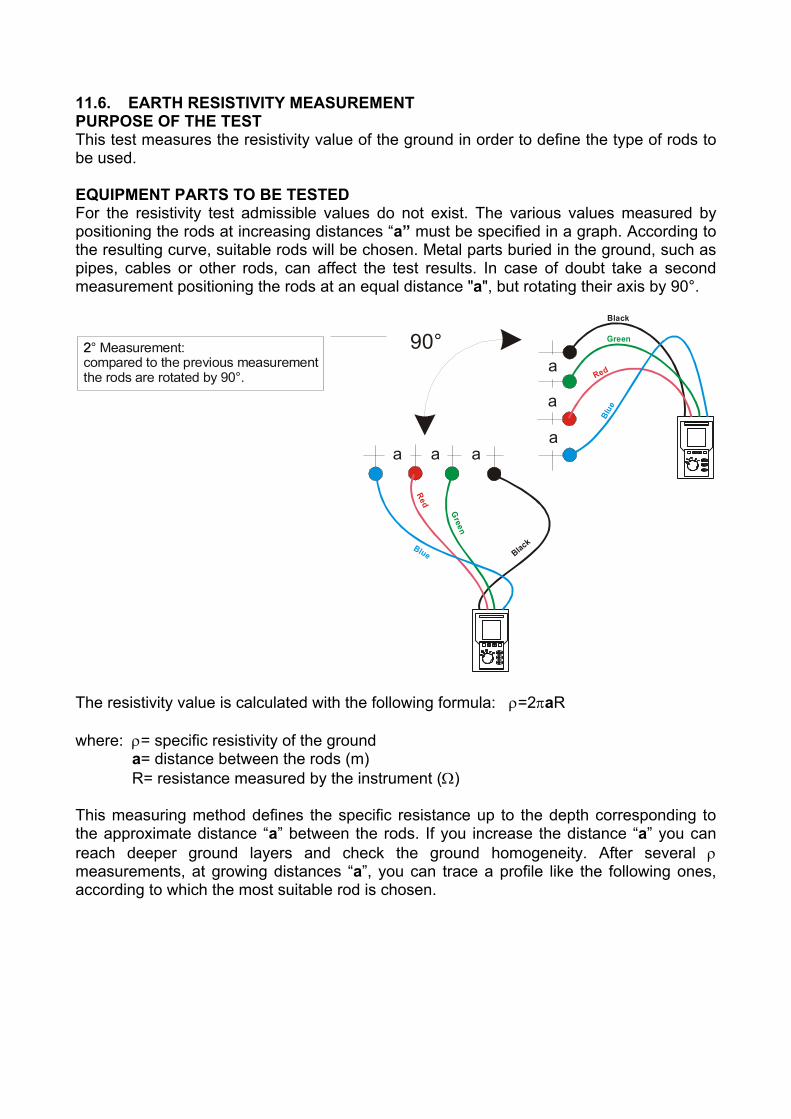
11.6. EARTH RESISTIVITY MEASUREMENT PURPOSE OF THE TEST This test measures the resistivity value of the ground in order to define the type of rods to be used. EQUIPMENT PARTS TO BE TESTED For the resistivity test admissible values do not exist. The various values measured by positioning the rods at increasing distances “a” must be specified in a graph. According to the resulting curve, suitable rods will be chosen. Metal parts buried in the ground, such as pipes, cables or other rods, can affect the test results. In case of doubt take a second measurement positioning the rods at an equal distance "a", but rotating their axis by 90°.
Black
Black
Blue
Blue
GreenG
reen
RedRed
a
a aa
a
a
90°2
90°.compared to the previous measurementthe rods are rotated by
2° Measurement:
The resistivity value is calculated with the following formula: ρ=2πaR where: ρ= specific resistivity of the ground a= distance between the rods (m) R= resistance measured by the instrument (Ω) This measuring method defines the specific resistance up to the depth corresponding to the approximate distance “a” between the rods. If you increase the distance “a” you can reach deeper ground layers and check the ground homogeneity. After several ρ measurements, at growing distances “a”, you can trace a profile like the following ones, according to which the most suitable rod is chosen.

Distance between the rods a(m)
Spec
ific re
sistiv
ity o
f the
gro
und
E
(m
)ρ
Ω
32
1
Curve 1: as ρ decreases only in depth, it’s possible to use only a rod in depth. Curve 2: as ρ decreases only until the depth A, it’s not useful to increase the depth of the rod beyond A. Curve 3: even at a superior depth, ρ does not decrease, therefore a ring rod must be used.
APPROXIMATE EVALUATION OF INTENTIONAL RODS CONTRIBUTION (64-12 2.4.1) The resistance of a rod Rd can be calculated with the following formulas (ρ = medium resistivity of the ground).
a) Resistance of a vertical rod
Rd = ρ / L
L= length of the element touching the ground
b) Resistance of a horizontal rod
Rd = 2ρ / L
L= length of the element touching the ground
c) Resistance of linked elements The resistance of a complex system with more elements in parallel is always greater than the resistance that could result from a simple calculation of elements in parallel, especially if those elements are close and therefore interactive. For this reason, in case of a linked system the following formula is quicker and more effective than the calculation of the single horizontal and vertical elements:
Rd = ρ / 4r r= radius of the circle which circumscribes the link
Copyright Amprobe 2003
Multi
Test
1000
Man
ual d
e In
stru
ccio
nes


AMPROBE MULTITEST1000
EN - 1
Indice:
1. PRECAUCIONES Y MEDIDAS DE SEGURIDAD ......................................................31.1. INSTRUCCIONES PRELIMINARES .................................................................................31.2. DURANTE EL USO ...........................................................................................................41.3. DESPUES DEL USO.........................................................................................................4
2. DESCRIPCION GENERAL.........................................................................................52.1. FUNCIONES......................................................................................................................52.2. DESCRIPCION DEL INSTRUMENTO ..............................................................................6
3. PREPARACION PARA EL USO ................................................................................73.1. CONTROLES INICIALES ..................................................................................................73.2. ALIMENTACION DEL INSTRUMENTO ............................................................................73.3. CALIBRACION ..................................................................................................................73.4. ALMACENAMIENTO .........................................................................................................73.5. SELECCIÓN DE IDIOMA Y UNIDAD DE MEDIDA ...........................................................8
4. DESCRIPCION DEL CONMUTADOR DE FUNCIONES ............................................94.1. LOWΩ: PRUEBA CONTINUIDAD DE CONDUCTORES DE PROTEC Y EQUIP. ...........9
4.1.1. MODALIDAD "CAL".......................................................................................................................104.1.2. PROCEDIMIENTO DE MEDIDA PARA LA CONTINUIDAD DE LOS CONDUCTORES EQUIPOTENCIALES
MODALIDAD "AUTO", "R+TIMER", "R-TIMER" ...........................................................................124.1.3. SITUACIONES ANOMALAS EN LAS PRUEBAS "AUTO", "R+TIMER", "R-TIMER" ..............................14
4.2. MΩ: MEDIDA DE LA RESISTENCIA DE AISLAMIENTO CON TENSION DE PRUEBADE 50V, 100V, 250V, 500V o 1000V .........................................................................15
4.2.1. PROCEDIMIENTO DE PRUEBA DE AISLAMIENTO EN TODAS LAS MODALIDADES ...................................164.2.2. SITUACIONES ANOMALAS EN LAS PRUEBAS "MAN" Y "TIMER" .......................................................20
4.3. : INDICADOR DE SECUENCIA DE FASES...............................................................214.3.1. MODALIDAD " "........................................................................................................................224.3.2. SITUACIONES ANOMALAS EN LAS PRUEBAS DE SECUENCIA DE FASES ..............................................23
4.4. EARTH ρ: MEDIDA DE LA RESISTENCIA Y RESISTIVIDAD DE TERRENO ...............254.4.1. PROCEDIMIENTO DE MEDIDA PARA LA MODALIDAD DE PRUEBA "2P".................................................264.4.2. PROCEDIMIENTO DE MEDIDA PARA LA MODALIDAD DE PRUEBA "3P".................................................294.4.3. PROCEDIMIENTO DE MEDIDA PARA LA MODALIDAD DE PRUEBA "ρ" ...................................................31
4.5. SITUACIONES ANOMALAS MODALIDAD EARTH ρ .....................................................335. COMO GUARDAR, RECUPERAR Y BORRAR DATOS GUARDADOS EN
MEMORIA.................................................................................................................355.1. TECLA GUARDAR: "SAVE" ............................................................................................355.2. TECLA RECUPERAR: "RCL"..........................................................................................365.3. TECLA BORRAR: "CLR" .................................................................................................37
6. RESETEADO DEL INSTRUMENTO Y DE LOS PARÁMETROS ESTANDAR........386.1. PROCEDIMIENTO DE RESETEADO .............................................................................386.2. PARAMETROS ESTANDAR ...........................................................................................38
7. CONEXIÓN DEL INSTRUMENTO A UN PC ............................................................398. MANTENIMIENTO ....................................................................................................40
8.1. GENERALIDADES ..........................................................................................................408.2. CAMBIO DE BATERIAS..................................................................................................408.3. LIMPIEZA DEL INSTRUMENTO .....................................................................................40
9. ESPECIFICACIONES TECNICAS............................................................................419.1. CARACTERISTICAS TECNICAS....................................................................................41
9.1.1. NORMAS DE SEGURIDAD ......................................................................................................429.1.2. CARACTERISTICAS GENERALES..........................................................................................42
9.2. AMBIENTE ......................................................................................................................439.2.1. CONDICIONES AMBIENTALES DE USO .............................................................................................439.2.2. EMC...........................................................................................................................................43
9.3. ACCESORIOS.................................................................................................................4310. ASISTENCIA.............................................................................................................44
10.1. CONDICIONES DE GARANTIA ......................................................................................4411. FICHAS PRACTICAS PARA LAS VERIFICACIONES ELECTRICAS.....................45
11.1. LOWΩ: MEDIDA CONTINUIDAD DE CONDUCTORES DE PROTECCION..................45

AMPROBE MULTITEST1000
EN - 2
11.2. MEDIDA DE LA RESISTENCIA DE AISLAMIENTO DE INSTALACIÓN ELECTRICA(250VDC, 500VDC, 1000VDC)........................................................................................46
11.3. MEDIDA DE LA RESISTENCIA DE AISLAMIENTO DE SUELOS EN LOCALES DEUSO MEDICO..................................................................................................................48
11.4. VERIFICACION DE LA SEPARACIÓN DE LOS CIRCUITOS ........................................4911.5. MEDIDA DE LA RESISTENCIA DE TIERRA, METODO VOLTIAMPERIMETRICO.......5211.6. MEDIDA DE LA RESISTIVIDAD DEL TERRENO...........................................................53
Release SP 1.00 del 01/05/2003
AMPROBE MULTITEST1000
SP - 3
1. PRECAUCIONES Y MEDIDAS DE SEGURIDADEl instrumento ha sido proyectado en conformidad a las directivas EN61557 y EN 61010-1relativas a los instrumentos de medida electrónicos.
ATENCIÓNPara su seguridad y para evitar dañar al instrumento, Le rogamos que sigalos procedimientos descritos en el presente manual y lea con particularatención todas las notas precedidas por el símbolo ..
Antes y durante la ejecución de las medidas fíjese atentamente en las siguientesindicaciones:
No efectúe medidas de tensión o corriente en ambientes húmedos. No efectúe medidas en presencia de gas, materiales explosivos o combustibles Evite el contacto con el circuito en examen si se está efectuando medidas. Evite el contacto con partes metálicas desnudas, con terminales de medida inutilizados,
circuitos, etc. No efectúe alguna medida si existe alguna anomalía en el instrumento como,
deformaciones, roturas, pérdidas de sustancias, ausencia de símbolos en elvisualizador, etc.
Preste particular atención cuando esté efectuando medidas de tensión superior a 25V enambientes especiales (obras, piscinas,..) y 50V en ambientes ordinarios en cuanto seencuentre en presencia de riesgo de choques eléctricos.
En el presente manual son utilizados los siguientes símbolos:
Atención: fíjese en las instrucciones reflejadas en el manual; un uso impropiopodría causar daños al instrumento y a sus componentes.
Tensión o Corriente CA.
Tensión o Corriente pulsante unidireccional.
Conmutador del Instrumento.
1.1. INSTRUCCIONES PRELIMINARES Este instrumento ha sido proyectado para su uso en ambientes de polución 2 Puede ser utilizado para comprobaciones en instalaciones eléctricas con categoría de
sobretensión 265V (a tierra).

AMPROBE MULTITEST1000
SP - 4
Le sugerimos que siga las reglas de seguridad orientadas a: Protegerle contra corrientes peligrosas. Proteja el instrumento contra un uso erróneo.
Sólo los accesorios incluidos con el equipo garantizan las normas de seguridad.Deben estar en buenas condiciones y si fuese necesario, sustituirlos por los modelosoriginales.
No efectúe medidas en circuitos que superen los límites de corriente y tensiónespecificados.
No efectúe medidas en condiciones ambientales fuera de los límites indicados en elpresente manual.
Controle que las baterías estén insertadas correctamente. Antes de conectar las puntas de prueba al circuito en examen, controle que el
conmutador esté posicionado correctamente. Controle que el visualizador y el conmutador indiquen la misma función.
1.2. DURANTE EL USOLe rogamos que lea atentamente las recomendaciones y las instrucciones siguientes:
ATENCIÓNLa falta de observación de las Advertencias y/o Instrucciones puede dañar elinstrumento y/o sus componentes o ser fuente de peligro para el usuario.
Antes de accionar el conmutador, quite las puntas de prueba del circuito en examen. Cuando el instrumento está conectado al circuito en examen no toque nunca cualquier
terminal inutilizado. Evite la medida de resistencia en presencia de tensiones externas; aunque el
instrumento está protegido, una tensión excesiva podría causar un mal funcionamientodel instrumento.
ATENCIÓNSi durante el uso aparece el símbolo suspenda la prueba y reemplacelas baterías siguiendo el procedimiento descrito en el párrafo. El instrumentoes capaz de mantener los datos guardados aunque las baterías no esténinstaladas.
1.3. DESPUÉS DEL USO Cuando las medidas han finalizado, apague el instrumento manteniendo pulsada la
tecla ON/OFF durante algunos segundos. Retire las baterías cuando el instrumento este mucho tiempo sin utilizar.

AMPROBE MULTITEST1000
SP - 5
2. DESCRIPCIÓN GENERALLe agradecemos que haya escogido un instrumento de nuestro programa de ventas. Elinstrumento que acaba de adquirir, si se utiliza según lo descrito en el presente manual, legarantizará medidas precisas y fiables.El instrumento está realizado de modo que garantiza la máxima seguridad gracias a undesarrollo de nueva concepción que asegura el doble aislamiento y el cumplimiento de lacategoría de sobretensión III.
2.1. FUNCIONES LOWΩ: Prueba de Continuidad de los Conductores de protección o equipotencial
con Corriente de Prueba superior a 200mA y tensión de vacíocomprendido entre 4V y 24V.
RISO: Medida de la Resistencia de Aislamiento con Tensión CC de Prueba 50V,100V, 250V, 500V o 1000V.
: Indicación de rotación de secuencia de fases EARTH ρ: Medida de la resistencia de tierra y de la resistividad del terreno a través
de picas auxiliares. RS232: Posición del conmutador para la posición de comunicación RS232.

AMPROBE MULTITEST1000
SP - 6
2.2. DESCRIPCION DEL INSTRUMENTO
1
2
3
DISP
RCL ESC
SAVE
CLR
START STOP
FUNC Un/I∆n DIST
S
UL
LEYENDA:
1. Visualizador2. Teclas Función3. Conmutador rotatorio
Tecla FUNCION para seleccionar la modalidad de medida.
Tecla Un / DIST para seleccionar la tensión nominal o distanciadependiendo de la medida seleccionada.
Tecla para aumentar el intervalo de duración de la prueba o paravisualizar los resultados de las medidas memorizadas.
Tecla para disminuir el intervalo de duración de la prueba o paravisualizar los resultados de las medidas memorizadas.
Tecla ON/OFF. Manténgala pulsada durante unos segundos para apagarel instrumento, suéltela cuando oiga la indicación acústica
Esta tecla Inicia (y Detiene) las medidas.
DISPLAY tecla para hojear los resultados.
CLEAR tecla para cancelar los resultados.
RECALL/ESCAPE tecla visualizar las pruebas memorizadas (RCL)Tecla para abandonar la función o modalidad (ESC).
Esta tecla permite la memorización de los resultados visualizados.
FUNC
STARTSTOP
CLR
RCLESC
DISP
SAVE
UnDIST

AMPROBE MULTITEST1000
SP - 7
3. PREPARACIÓN PARA EL USO3.1. CONTROLES INICIALES
El instrumento, antes de ser expedido, ha sido controlado desde el punto de vista eléctricoy mecánico.Han sido tomadas todas las precauciones posibles con el fin que el instrumento pueda serentregado sin ningún daño.
De todas formas se aconseja controlar exhaustivamente el instrumento para comprobarque no haya sufrido daños durante el transporte. Si se detecta alguna anomalía contacteinmediatamente con la sociedad Amprobe.
Se aconseja además controlar que el embalaje contenga todas las partes indicadas en elpárrafo 14.5. En caso de discrepancias contacte con el distribuidor.
En caso de que fuera necesario devolver el instrumento, se ruega seguir las instruccionesindicadas en el párrafo 10.
3.2. ALIMENTACIÓN DEL INSTRUMENTO
El instrumento se alimenta mediante seis baterías referencia AA no incluidas en elembalaje. Para la colocación de las baterías siga las indicaciones del párrafo 8.2.
Cuando las baterías estén descargadas aparece el símbolo. . Para sustituirlas siga lasinstrucciones indicadas al párrafo 8.2.
3.3. CALIBRACIÓN
El instrumento respeta las características técnicas reflejadas en el presente manual. Lasprestaciones del instrumento están garantizadas durante un año desde la fecha deadquisición.
3.4. ALMACENAMIENTO
Para garantizar medidas precisas, después de un largo período de almacenamiento encondiciones ambientales extremas, espere que el instrumento vuelva a las condicionesnormales (ver especificaciones ambientales listadas en el párrafo 9.2.1.)
AMPROBE MULTITEST1000
SP - 8
3.5. SELECCIÓN DE IDIOMA Y UNIDAD DE MEDIDAEs posible configurar el idioma y la unidad de medida (en resistividad de terreno)siguiendo el procedimiento:
1. Mientras mantiene la tecla FUNC pulsada, encienda el instrumento ON (la posición delconmutador no es relevante.
2.
le m
El instrumento visualizará la siguientepantalla.
3. Pulse la tecla SAVE para confirmar laelección. El instrumento visualizará lasiguiente pantalla. le m
OKPulsando la tecla ESC saldrá del menúsin confirmar ningún cambio.
AMPROBE MULTITEST1000
SP - 9
4. DESCRIPCIÓN DEL CONMUTADOR DE FUNCIONES4.1. LOWΩ: PRUEBA DE CONTINUIDAD DE LOS CONDUCTORES DE
PROTECCIÓN Y EQUIPOTENCIALIDADLas pruebas se realizan a una corriente de prueba superior a 200 mA y una tensión decortocircuito desde 4 a 24V DC de acuerdo a EN 61557-2 y VDE 0413 parte 4.
ATENCIÓNAntes de realizar la prueba de Continuidad asegurarse que no haya tensión alfinal del conductor que debemos analizar.
Gire el conmutador en posición LOWΩ.
Encienda el instrumento.
Con la tecla FUNC es posible seleccionar una de las siguientes modalidadesde medida:
Modalidad “AUTO” (el instrumento efectúa dos medidas de polaridad R+y R-, polaridad y visualiza el valor medio Ravg). Modalidad aconsejadapara la prueba de continuidad.
Modalidad “R + TIMER” (medida con polaridad positiva y con laposibilidad de programar el tiempo de duración de la prueba). En estecaso el usuario puede programar el tiempo de medida suficientementelargo para poder mover los conductores de protección mientras elinstrumento está ejecutando la prueba y poder localizar una eventualconexión errónea.
Modalidad “R - TIMER” (medida con polaridad negativa y con laposibilidad de programar el tiempo de duración de la prueba). En estecaso el usuario puede programar el tiempo de medida suficientementelargo para poder mover los conductores de protección mientras elinstrumento está ejecutando la prueba y poder localizar una eventualconexión errónea.
Modalidad “CAL” (compensación de la resistencia de los cablesutilizados para la medida).
Nota La prueba de continuidad se realiza inyectando una corriente superior a 200mAen el caso en el que la resistencia no sea superior a 5Ω (comprendida laresistencia de los cables de medida memorizada como offset en el instrumentodespués de haber realizado el procedimiento de calibración). Para valores deresistencia superiores el instrumento realiza la prueba con una corriente inferior a200mA.
FUNC

AMPROBE MULTITEST1000
SP - 10
4.1.1. Modalidad "CAL"1. Seleccione la modalidad CAL usando la tecla FUNC.2. Inserte el cable Negro y el cable Azul en los respectivos terminales de entrada T1 y T4
del instrumento
T2 T3 T4T1
Conexión de los terminales del instrumento durante el procedimiento de calibración
3. Si, para realizar una medida, la longitud de los cables en dotación fuera insuficienteprolongar el cable azul.
4. Conecte los cocodrilos a los terminales de los cables.5. Cortocircuitar las terminaciones de los cables de medida teniendo cuidado que las partes
conductoras de los cocodrilos realicen un buen contacto reciproco (ver figura anterior).
6. Pulse la tecla START/STOP. El instrumento efectuará la calibración.
Nota: El instrumento realiza la calibración de los cables de medida sólo si la resistenciade estos últimos es inferior a 5Ω.
CAL LOWΩ 0.00Ω
203 mA
Al término de la pruebael valor medido estámemorizado en elinstrumento y loutilizará comoCOMPENSACIÓN (esdecir será anulado entodas las medidas decontinuidad que serealicen) hasta unanueva calibración.La pantalla visualizará en 2 segundos almismo tiempo que el instrumento emite unadoble señal acústica (señalando lacalibración) y visualiza la pantalla estándarrelativa a la prueba LOWΩ modo AUTO.
Mensaje: CAL:significa que elinstrumentoestácalibrado;este símbolo serávisualizado ensucesivasmedidas aunqueel instrumento seapaga.
STARTSTOP
Corrienteaplicada por elinstrumentodurante elprocedimiento decalibración.

AMPROBE MULTITEST1000
SP - 11
PUNTAS DE PRUEBA Asegurarse siempre, antes de cada medida, quela calibración se refiera a los cables utilizados enel momento. En una medida de continuidad si elvalor de resistencia depurado de la calibración (esdecir valor de la resistencia menos el valor deloffset de la calibración) resultase negativo, sevisualizaría el símbolo . Probablemente lacalibración memorizada en el instrumento no serefiere a los cables en uso, por lo tanto debe serrealizada una nueva calibración. (referenciado a la5ª pantalla del párrafo 4.1.3.).
ATENCIÓNNo desconectar nunca los terminales de los puntos de medida cuando elinstrumento visualiza el mensaje "MEASURING"
4.1.1.1. Procedimiento para borrar los parámetros de calibración del símbolo cal
LOWΩ
>5 Ωcal
Measuring
Para borrar los parámetros de calibración (yel símbolo CAL de la pantalla) hace faltaefectuar un procedimiento de calibracióncon una resistencia en las puntas deprueba superior a 5Ω (por ejemplo con laspuntas de prueba abiertas). Cuando seefectúa una cancelación se visualizará laprimera pantalla (ver derecha), luegoaparecerá la pantalla siguiente.
LOWΩ escal
La pantalla se visualizará en 2 segundos,transcurrido este tiempo, el instrumentoemite una señal acústica prolongada yluego aparecerá en pantalla la prueba LOWΩ modo AUTO.
Mensaje >5Ω:significa que elinstrumento ha leidouna resistenciasuperior a 5Ω portanto procederá aResetear.
Mensaje rES:significa que elinstrumento haejecutado lacancelación(RESET) de losparámetros decalibración

AMPROBE MULTITEST1000
SP - 12
4.1.2. Procedimiento de medida para la continuidad de los conductoresequipotenciales modalidad AUTO, R+TIMER, R-TIMER
1. Seleccione con la tecla FUNC la modalidad que interese.2. Inserte el cable Negro y el Azul en los correspondientes terminales de entrada T1 y T4
del instrumento
T2 T3 T4T1
Conexión de las terminales del instrumento prueba LOW Ω.
3. Si para efectuar la medida es necesario alargar la longitud de los cables incluidos essuficiente con alargar el cable azul.
4. Conecte los cocodrilos en los terminales de los cables.5. Cortocircuite los terminales de los cables de medida con la precaución que hagan buen
contacto entre ellos. Presione la tecla GO. Si el instrumento visualiza un valor deresistencia superior a 0,00 repita la calibración del instrumento (ver párrafo 4.1.1).
6. Conecte los terminales del instrumento al conductor que desee comprobar (ver figuraanterior).
7. Si ha sido seleccionada la modalidad R+TIMER o R- TIMER utilice las siguientesteclas para elegir el tiempo de duración de la prueba
Presione esta tecla para aumentar el tiempo de duración de la prueba(Tmax=15 segundos).
Presione esta tecla para disminuir el tiempo de duración de la prueba(Tmin=1 segundos).
8. Pulse la tecla START/STOP. El instrumento realizará la medida.En modalidad R+/ R- púlsela tecla START/STOP de nuevo si se quieredetener la prueba.
ATENCIÓNNo desconectar nunca los terminales de los puntos de medida cuando elinstrumento visualiza el mensaje "MEASURING"
STARTSTOP
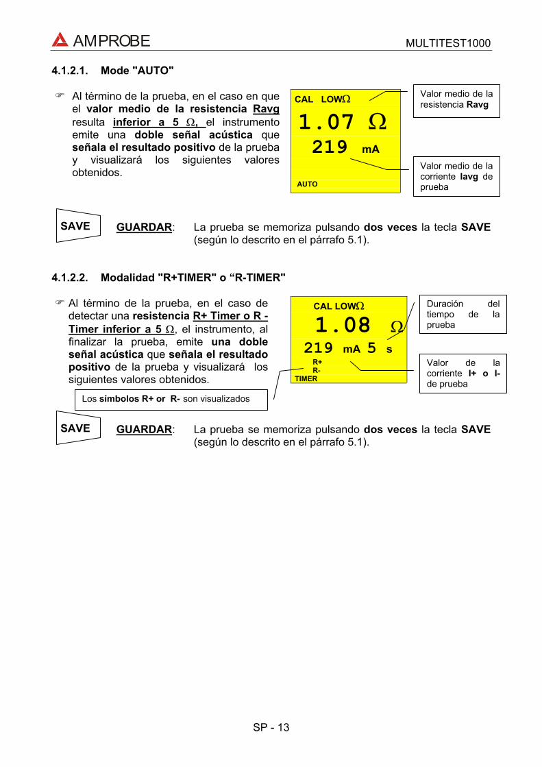
AMPROBE MULTITEST1000
SP - 13
4.1.2.1. Mode "AUTO"
CAL LOWΩ
1.07 Ω219 mA
AUTO
Al término de la prueba, en el caso en queel valor medio de la resistencia Ravgresulta inferior a 5 Ω, el instrumentoemite una doble señal acústica queseñala el resultado positivo de la pruebay visualizará los siguientes valoresobtenidos.
GUARDAR: La prueba se memoriza pulsando dos veces la tecla SAVE(según lo descrito en el párrafo 5.1).
4.1.2.2. Modalidad "R+TIMER" o “R-TIMER"
CAL LOWΩ
1.08 Ω219 mA 5 s
R+R-
TIMER
Al término de la prueba, en el caso dedetectar una resistencia R+ Timer o R -Timer inferior a 5 Ω, el instrumento, alfinalizar la prueba, emite una dobleseñal acústica que señala el resultadopositivo de la prueba y visualizará lossiguientes valores obtenidos.
GUARDAR: La prueba se memoriza pulsando dos veces la tecla SAVE(según lo descrito en el párrafo 5.1).
Valor medio de lacorriente Iavg deprueba
Valor medio de laresistencia Ravg
Valor de lacorriente I+ o I-de prueba
Los símbolos R+ or R- son visualizados
Duración deltiempo de laprueba
SAVE
SAVE
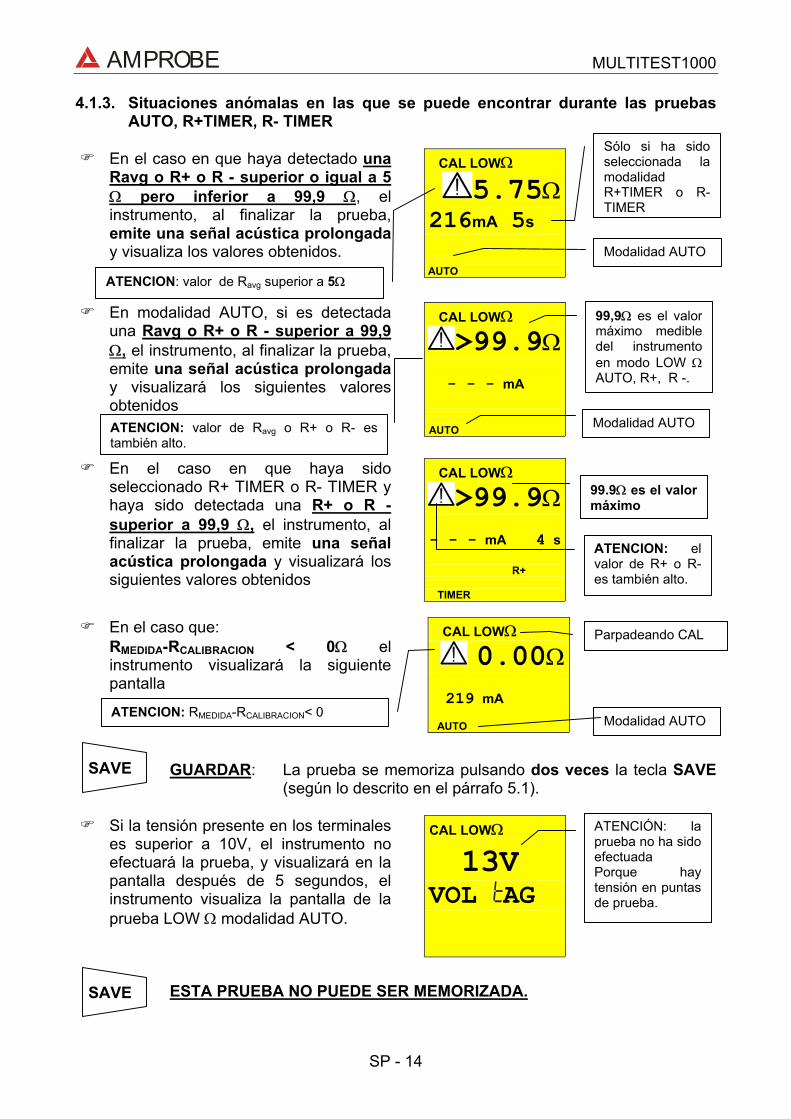
AMPROBE MULTITEST1000
SP - 14
4.1.3. Situaciones anómalas en las que se puede encontrar durante las pruebasAUTO, R+TIMER, R- TIMER
CAL LOWΩ
5.75Ω216mA 5s
AUTO
En el caso en que haya detectado unaRavg o R+ o R - superior o igual a 5Ω pero inferior a 99,9 Ω, elinstrumento, al finalizar la prueba,emite una señal acústica prolongaday visualiza los valores obtenidos.
CAL LOWΩ
>99.9Ω
- - - mA
AUTO
En modalidad AUTO, si es detectadauna Ravg o R+ o R - superior a 99,9Ω, el instrumento, al finalizar la prueba,emite una señal acústica prolongaday visualizará los siguientes valoresobtenidos
CAL LOWΩ
>99.9Ω
- - - mA 4 s
R+
TIMER
En el caso en que haya sidoseleccionado R+ TIMER o R- TIMER yhaya sido detectada una R+ o R -superior a 99,9 Ω, el instrumento, alfinalizar la prueba, emite una señalacústica prolongada y visualizará lossiguientes valores obtenidos
CAL LOWΩ
0.00Ω
219 mA
AUTO
En el caso que:RMEDIDA-RCALIBRACION < 0Ω elinstrumento visualizará la siguientepantalla
GUARDAR: La prueba se memoriza pulsando dos veces la tecla SAVE(según lo descrito en el párrafo 5.1).
CAL LOWΩ
13V
VOL AG
Si la tensión presente en los terminaleses superior a 10V, el instrumento noefectuará la prueba, y visualizará en lapantalla después de 5 segundos, elinstrumento visualiza la pantalla de laprueba LOW Ω modalidad AUTO.
ESTA PRUEBA NO PUEDE SER MEMORIZADA.
ATENCION: valor de Ravg superior a 5Ω
99,9Ω es el valormáximo medibledel instrumentoen modo LOW ΩAUTO, R+, R -.
99.9Ω es el valormáximo
Modalidad AUTO
Modalidad AUTOATENCION: valor de Ravg o R+ o R- estambién alto.
ATENCION: elvalor de R+ o R-es también alto.
Sólo si ha sidoseleccionada lamodalidadR+TIMER o R-TIMER
Parpadeando CAL
ATENCION: RMEDIDA-RCALIBRACION< 0 Modalidad AUTO
SAVE
ATENCIÓN: laprueba no ha sidoefectuadaPorque haytensión en puntasde prueba.
SAVE

AMPROBE MULTITEST1000
SP - 15
4.2. MΩ: MEDIDA DE LA RESISTENCIA DE AISLAMIENTO CON TENSIÓN DEPRUEBA DE 50V, 100V, 250V, 500V O 1000V
Referente a EN 61557-2 y VDE 0413 parte 1.
ATENCIÓNAntes de realizar la prueba de aislamiento asegurarse que el circuito enexamen no esté alimentado y que todas las cargas de él derivadas esténdesconectadas.
Gire el selector en posición MΩ.
Encienda el instrumento.
La tecla FUNC permite seleccionar una de las siguientes modalidades demedida (se presenta cíclicamente al presionar la tecla FUNC):
Modalidad “MAN” (tiempo de prueba mínima de 4 segundos odeterminado por la duración de la presión de la tecla START/STOP).prueba recomendada.
Modalidad “TIMER” (duración de la prueba que depende del intervaloseleccionado (de 10 a 999 segundos)). Esta prueba puede ser ejecutadaen el caso en que sea solicitado un tiempo mínimo de medida.
FUNC
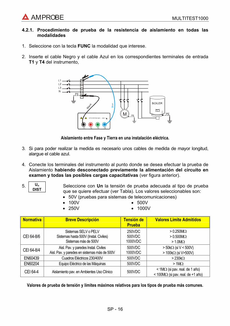
AMPROBE MULTITEST1000
SP - 16
4.2.1. Procedimiento de prueba de la resistencia de aislamiento en todas lasmodalidades
1. Seleccione con la tecla FUNC la modalidad que interese.
2. Inserte el cable Negro y el cable Azul en los correspondientes terminales de entradaT1 y T4 del instrumento,
T2 T3 T4T1
M
Aislamiento entre Fase y Tierra en una instalación eléctrica.
3. Si para poder realizar la medida es necesario unos cables de medida de mayor longitud,alargue el cable azul.
4. Conecte los terminales del instrumento al punto donde se desea efectuar la prueba deAislamiento habiendo desconectado previamente la alimentación del circuito enexamen y todas las posibles cargas capacitativas (ver figura anterior).
5. Seleccione con Un la tensión de prueba adecuada al tipo de pruebaque se quiere efectuar (ver Tabla). Los valores seleccionables son:• 50V (pruebas para sistemas de telecomunicaciones)• 100V • 500V• 250V • 1000V
Normativa Breve Descripción Tensión dePrueba
Valores Límite Admitidos
CEI 64-8/6Sistemas SELV o PELV
Sistemas hasta 500V (Instal. Civiles)Sistemas más de 500V
250VDC500VDC
1000VDC
> 0.250MΩ> 0.500MΩ> 1.0MΩ
CEI 64-8/4 Aisl. Pav. y paredes Instal. CivilesAisl. Pav. y paredes en sistemas más de 500V
500VDC1000VDC
> 50kΩ (si V < 500V)> 100kΩ (si V>500V)
EN60439 Cuadros Eléctricos 230/400V 500VDC > 230kΩEN60204 Equipo Eléctrico de las Máquinas 500VDC > 1MΩ
CEI 64-4 Aislamiento pav. en Ambientes Uso Clínico 500VDC < 1MΩ (si pav. real. de 1 año)< 100MΩ (si pav. real. de +1 año)
Valores de prueba de tensión y límites máximos relativos para los tipos de prueba más comunes.
UnDIST

AMPROBE MULTITEST1000
SP - 17
ATENCIÓNSi en el visualizador del instrumento aparece el mensaje “Measuring” elinstrumento está ejecutando la medida. No desconecte nunca las puntas deprueba durante la medida ya que el circuito en examen podría quedarcargado a una tensión peligrosa a causa de la capacidad parásita de lainstalación. Cualquier modo de funcionamiento seleccionado en elinstrumento en la parte final de cada prueba inserta una resistencia a laspuntas de prueba de salida para efectuar la descarga de las capacidadesparásitas presentes en el circuito.

AMPROBE MULTITEST1000
SP - 18
4.2.1.1. Modalidad "MAN"
6. Pulse la tecla START/STOP.
El instrumento efectúa la medida con una duración: Mínimo 4 segundos en el caso de pulsar y soltar la tecla. Siempre que la tecla no esté en todos los otros casos.
RISO
1.00MΩ500 V 20 s
MAN
Al término de la prueba, en el caso enque el valor de la resistencia RISOresulte inferior a RMAX (que dependede la tensión aplicada ver siguienteTabla 4), el instrumento, emite unadoble señal acústica que señala elresultado positivo de la prueba yvisualizará los valores obtenidos
Tal valor de la medida de resistencia de aislamiento siempre será conforme con los límitesnormativos (ver tabla) para comprobar si el sistema es correcto.
GUARDAR: La prueba se memoriza pulsando dos veces la tecla SAVE(según lo descrito en el párrafo 5.1).
Valor de la tensión nominalseleccionada en la prueba
Duración de laprueba. En estecaso la teclaSTART/STOP hasido presionadadurante 20segundos
Modalidad Manual
SAVE
RISO Valor de laresistencia deaislamiento.
STARTSTOP

AMPROBE MULTITEST1000
SP - 19
4.2.1.2. Modalidad "TIMER"
6. Use las siguientes teclas para seleccionar la duración de la prueba:
Pulse esta tecla para aumentar la duración de la prueba (Tmax=999segundos).
Pulse esta tecla para disminuir la duración de la prueba (Tmin=10segundos).
7. Pulse la tecla START/STOP .
El instrumento efectúa la medida acabando en tiempo programado.999 segundos Valor máximo de la duración de la prueba. 10 segundos Valor mínimo de la duración de la prueba.
Nota: Pulse una segunda vez la tecla START/STOP GO si se quiere detener la prueba encurso.
RISO 2.07MΩ500 V 20s
TIMER
Al término de la prueba, en el caso enque el valor de la resistencia RISOresulte inferior a RMAX (que depende dela tensión aplicada ver siguiente Tabla),y que la prueba sea realizada al valorde tensión seleccionado, elinstrumento, emite una doble señalacústica que señala el resultadopositivo de la prueba y visualiza losvalores obtenidos.
GUARDAR: La prueba se memoriza pulsando dos veces la tecla SAVE(según lo descrito en el párrafo 5.1).
Nota: El valor máximo de resistencia RMAX que el instrumento puede medir en lamodalidad RISO depende de la tensión nominal seleccionada para la prueba. Enparticular tendremos:
Tensión Nominal Seleccionadapara la prueba
RMAX = VALOR MÁXIMO DERESISTENCIA MEDIDA
50VDC 99.9MΩ100VDC 199.9MΩ250VDC 499MΩ500VDC 999MΩ1000VDC 1999MΩ
Valores máximos de resistencia que el instrumento mide en modo RISO en función de la tensiónnominal seleccionada.
Modalidad Timer
Duración de laprueba
Valor de laresistencia deaislamiento RISO.
Valor de la tensión nominal seleccionada en laprueba TIMER
SAVE
STARTSTOP

AMPROBE MULTITEST1000
SP - 20
4.2.2. Situaciones anómalas en la que se puede encontrar durante las pruebas"MAN" & "TIMER"
RISO >999 MΩ500 V 20 s
MAN
Al término de la prueba, en el caso enque el valor de la resistencia RISOresulte superior a RMAX (que dependede la tensión aplicada ver anterior Tabla4), el instrumento, emite una dobleseñal acústica que señala elresultado positivo de la prueba yvisualizará los valores obtenidos.
RISO 0.01MΩ500 V 20 s
MAN
En el caso en que haya efectuado laprueba a una tensión inferior a lanominal programada, el instrumento,emite una señal acústica prolongaday visualizará los valores obtenidos.
GUARDAR: La prueba se memoriza pulsando dos veces la tecla SAVE(según lo descrito en el párrafo 5.1).
RISO 33V
VOL AG
Si la tensión presente entre losterminales es mayor de 30V, elinstrumento no efectuará la prueba,visualizará después de 5 segundos, enla pantalla como en la prueba RISOmodalidad seleccionada.
ESTE RESULTADO NO SE PUEDE GUARDAR EN MEMORIA.
ATENCIÓN: laprueba no ha sidoefectuada.Verifique que elcircuito no tengapresencia detensión.
El símbolo ">"significa que elvalor de laresistencia RISO esmayor que RMAX
Duración de laprueba
Modalidadseleccionada MAN
Modalidadseleccionada MAN
ATENCIÓN: la prueba de la resistencia RISO hasido efectuada a un valor de tensión inferior alvalor de la tensión nominal programada. Situaciónque se puede averiguar en caso de bajoaislamiento o en presencia de tensionescapacitativas sobre la instalación
Máximo valor de resistencia que puede ser medido(999MΩ es visualizado si la tensión de 500V fueseleccionada, ver tabla).
SAVE
SAVE

AMPROBE MULTITEST1000
SP - 21
4.3. : INDICADOR DE SECUENCIA DE FASES
Gire el conmutador en la posición.
Encienda el instrumento.
ATENCIÓNNo desconectar nunca los terminales de los puntos de medida cuando elinstrumento visualiza el mensaje "MEASURING"
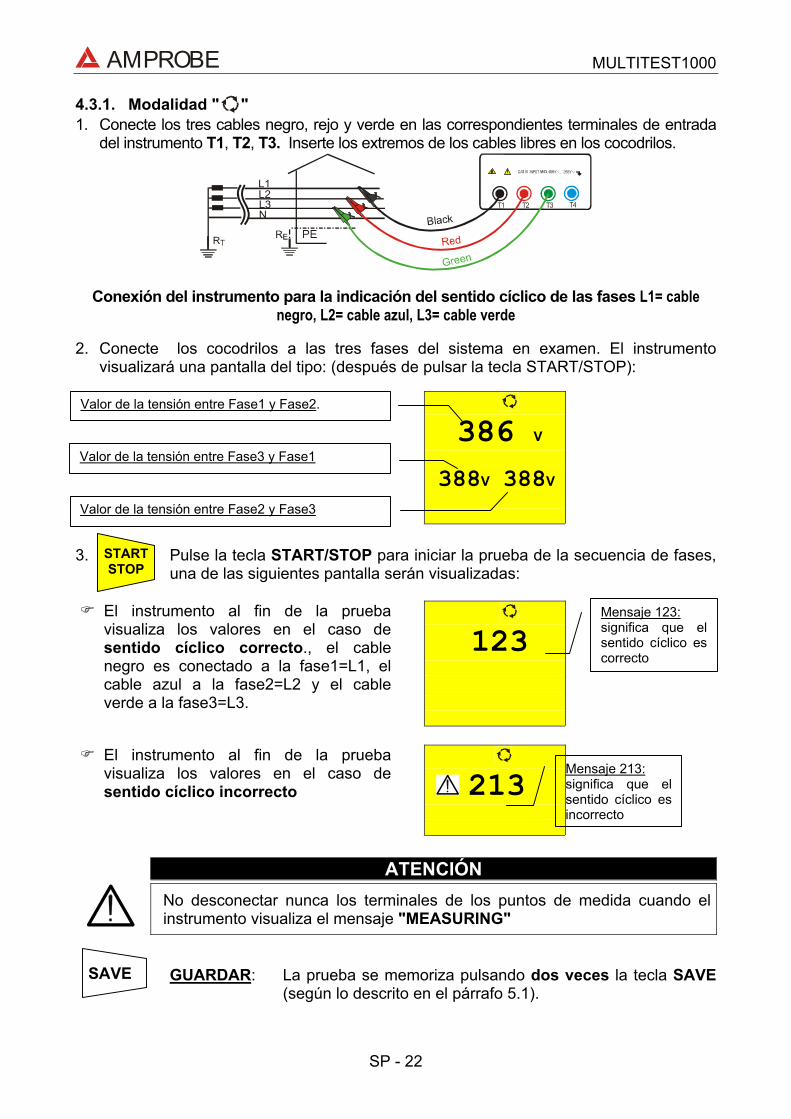
AMPROBE MULTITEST1000
SP - 22
4.3.1. Modalidad " "1. Conecte los tres cables negro, rejo y verde en las correspondientes terminales de entrada
del instrumento T1, T2, T3. Inserte los extremos de los cables libres en los cocodrilos.
T2 T3 T4T1
L1L2L3N
Conexión del instrumento para la indicación del sentido cíclico de las fases L1= cablenegro, L2= cable azul, L3= cable verde
2. Conecte los cocodrilos a las tres fases del sistema en examen. El instrumentovisualizará una pantalla del tipo: (después de pulsar la tecla START/STOP):
386 V
388V 388V
3. Pulse la tecla START/STOP para iniciar la prueba de la secuencia de fases,una de las siguientes pantalla serán visualizadas:
123
El instrumento al fin de la pruebavisualiza los valores en el caso desentido cíclico correcto., el cablenegro es conectado a la fase1=L1, elcable azul a la fase2=L2 y el cableverde a la fase3=L3.
213El instrumento al fin de la pruebavisualiza los valores en el caso desentido cíclico incorrecto
ATENCIÓNNo desconectar nunca los terminales de los puntos de medida cuando elinstrumento visualiza el mensaje "MEASURING"
GUARDAR: La prueba se memoriza pulsando dos veces la tecla SAVE(según lo descrito en el párrafo 5.1).
Mensaje 123:significa que elsentido cíclico escorrecto
Mensaje 213:significa que elsentido cíclico esincorrecto
Valor de la tensión entre Fase1 y Fase2.
Valor de la tensión entre Fase3 y Fase1
Valor de la tensión entre Fase2 y Fase3
SAVE
STARTSTOP

AMPROBE MULTITEST1000
SP - 23
4.3.2. Situaciones anómalas que se puede encontrar durante las pruebas deSentido Cíclico de las Fases
L VOL AG
En el caso en que el instrumentodetecte al menos una de las tensionespresentes entre dos de las fases enexamen sea inferior a 100V, noefectuará la prueba y visualizará lasiguiente pantalla:
A
l1Si la tensión de la entrada T1 es muybaja, cuando pulse START/STOP elinstrumento visualizará la siguientepantalla.
A
l2Si la tensión de la entrada T2 es muybaja, cuando pulse START/STOP elinstrumento visualizará la siguientepantalla.
A
l3Si la tensión de la entrada T3 es muybaja, cuando pulse START/STOP elinstrumento visualizará la siguientepantalla.
ph
Si dos cables de medida sonconectados a un mismo conductor defase, cuando pulse START/STOP elinstrumento visualizará la siguientepantalla.
ESTE RESULTADO NO PUEDE SER MEMORIZADO.
Mensaje “LoVOL tAG”:el instrumentodetecta unatensióndemasiado bajay no puedeefectuar laprueba.
SAVE
Mensaje “Att noL1”: tensión defase 1 es muybaja
Mensaje “Att noL2”: tensión defase 2 es muybaja
Mensaje “Att noL3”: tensión defase 3 es muybaja
Mensaje “PHdouble”: Dosfases estánconectadasjuntas.

AMPROBE MULTITEST1000
SP - 24
0 V
0 V 0 V
Si dos o más cables del instrumento noestán conectados, será visualizada lasiguiente pantalla.
GUARDAR: La prueba se memoriza pulsando dos veces la tecla SAVE(según lo descrito en el párrafo 5.1).
0 V
0 V 388V
Si un cable no está conectado a lainstalación o una fase no está presente,el instrumento visualizará la siguientepantalla
Cable negro= L1 no está conectado a una fase dela instalación. Tensión entre la fase L1 y fase L2es nula (L1- L2).
Cable negro= L1 no está conectado a una fase dela instalación. Tensión entre la fase L3 y fase L1es nula (L3- L1).
Cable negro= L1no estáconectado a unafase de lainstalación.Tensión entre lafase L2 y fase L3es nula (L2- L3).
SAVE
AMPROBE MULTITEST1000
SP - 25
4.4. EARTH ρ: MEDIDA DE LA RESISTENCIA DE TIERRA Y DE LA RESISTIVIDADDEL TERRENO
Gire el conmutador en posición EARTH ρ.
Encienda el instrumento.
La tecla FUNC permite seleccionar una de las siguientes modalidades (quese presentan en orden cíclico):
Modalidad “2P” (el instrumento realiza la medida de la Resistencia entre2 puntos).
Modalidad “3P” (el instrumento realiza la medida de la Resistenciautilizando 2 picas auxiliares).
Modalidad “ρ“ (el instrumento mide la resistividad del Terreno).
La resistencia es medida con el método voltiamperimétrico de 4 cables, el valor medido nodependerá de los cables utilizados. Para este fin no es necesario la calibración de loscables.
Si los cables no son los suficientemente largos, alárguelos o utilice cables más largos quelos incluidos en dotación.
FUNC

AMPROBE MULTITEST1000
SP - 26
4.4.1. Procedimiento de medida para la modalidad de prueba "2P"1. Seleccione "2P" modalidad de medida de tierra usando la tecla FUNC.2. Conecte los cables Negro, Rojo, Verde y Azul a los respectivos terminales de entrada del
instrumento T1, T2, T3, T4 (ver posibles conexiones siguientes).3. Conecte el cable negro y verde a la tierra a comprobar y los cables rojo y azul a una pica
auxiliar.
T2 T3 T4T1
Conexión para la medida a 2 puntos
4. Pulse la tecla START/STOP. El instrumento inicia la prueba.
EARTH0.96 Ω
2P 0.93 Ω
Cuando esté acabada la prueba elinstrumento visualizará los valoressiguientes.
ATENCIÓNNo desconectar nunca los terminales de los puntos de medida cuando elinstrumento visualiza el mensaje "MEASURING"
GUARDAR: La prueba se memoriza pulsando dos veces la tecla SAVE(según lo descrito en el párrafo 5.1).
Nota: Si la tecla START/STOP es pulsada y mantenida, el instrumento realizará máspruebas consecutivamente.
5. Cuando un nuevo valor es obtenido por el instrumento, emite un corto sonido y calculaun nuevo valor promedio.
6. Pulse la tecla DISP mostrará el valor promedio calculado y la modalidadde promedio.
7. Pulse la tecla CLR si quiere cancelar el valor medio de la resistencia y elnúmero de mediciones incluidas en el cálculo.
STARTSTOP
Modalidad “2P”.
Valor de laResistencia medida
Valor Promedio calculado de la resistencia detierra según el número de pruebas visualizadas.
CLR
DISP
SAVE

AMPROBE MULTITEST1000
SP - 27
Cuando las condiciones de trabajo impiden la realización de la modalidad de “3P” comopor ejemplo en el centro de la ciudad. En sistemas TT es posible medir la resistencia detierra con el método simplificado “2P” que proporciona un valor superior a la modalidad“3P”.Es necesario una pica auxiliar; debe tener una resistencia de tierra no significativa y debeser independiente del sistema de tierra en prueba.En el dibujo anterior se utiliza una tubería de agua como pica auxiliar. Pero cualquierobjeto metálico con conexión a tierra puede ser utilizado.
Ejemplo: Si el usuario realiza tres pruebas consecutivas el instrumento visualiza1ª medida:
visualización principal = valor de la resistencia medida (Ej: 0.90Ω)visualización secundaria en el lado izquierdo = 001 (nº. de mediciones = 1significa que se ha realizado 1 medida de tierra)visualización secundaria = promedio de mediciones realizadas (en el casode haber realizado una sola medición el valor medio es igual al valormedido, en este caso 0.90Ω)
2ª medición:visualización principal = valor de la resistencia medida (Ex: 0.96Ω)visualización secundaria = promedio de mediciones realizadas((Val1+Val2)/ nº. de mediciones = (0.90+0.96)/2 = 0.93Ω)
3ª medición:visualización principal = valor de la resistencia medida (Ex: 0.93Ω)visualización secundaria = promedio de mediciones realizadas((Val1+Val2)/ nº. de mediciones = (0.90+0.96+0.93)/3 = 0.93Ω)
Nota Cualquier medida con resultado mayor a 1999Ω no se incluye en el cálculo delvalor medio.
Ejemplo: 1ª medición:visualización principal: 1.07Ωvisualización secundaria: 1.07Ω
2ª medición:visualización principal: 4.15Ωvisualización secundaria: 2.61Ω
3ª medición: (no incluida en el valor medio)visualización principal: >1999Ωvisualización secundaria: 2.61Ω

AMPROBE MULTITEST1000
SP - 28
4.4.1.1. Medida de la resistencia de tierra desde una toma de corrienteEn instalaciones TT es posible realizar medidas de tierra con el método simplificado queproporciona un valor por exceso (por lo tanto más seguro), utilizando el NEUTRO de lacompañía eléctrica tomado directamente de la toma de corriente como pica auxiliar; siestá también disponible la conexión de tierra, la medición, naturalmente puede serrealizada directamente en la toma de corriente entre NEUTRO y TIERRA.Aunque esta prueba no está contemplada por la CEI 64.8 proporciona un valor que trasmuchas comparaciones con el método 3-wires ha demostrado ser indicativo de laresistencia de tierra.
T2 T3 T4T1
Medida de Tierra con el método simplificado en el cuadro eléctrico
ATENCIÓNSi quiere realizar la medición utilizando el neutro y el tierra de una instalaciónestándar, puede accidentalmente conectarlo a la fase. En este caso elvisualizador mostrará la tensión, el símbolo (conexión incorrecta) y no serealizará aunque pulsemos START/STOP.
ATENCIÓNNo desconectar nunca los terminales de los puntos de medida cuando elinstrumento visualiza el mensaje "MEASURING"

AMPROBE MULTITEST1000
SP - 29
4.4.2. Procedimiento de medida para la modalidad de prueba "3P"Las medidas son realizadas de acuerdo a las normas CEI 64.8, IEC 781, VDE 0413,EN61557-5.
1. Seleccione la modalidad de medida de tierra "3P" usando la tecla FUNC.2. Conecte el cable Negro, Rojo, Verde y Azul a los correspondientes terminales de entrada
del instrumento T1, T2, T3, T43. Conecte el cable negro y verde a la tierra a comprobar y los cables rojo y azul a una pica
auxiliar.
T2 T3 T4T1
Conexión para la medida a 3 puntos
Realizando mediciones de pequeños sistemas de tierra, la pica de corriente debe serposicionada a una distancia de la tierra en pruebas correspondiente a 5 veces la diagonaldel área del sistema de tierra en prueba, realizando mediciones en grandes sistemas ladistancia podría reducirse a una vez la diagonal.
4. Pulse la tecla START/STOP. El instrumento inicia la prueba.
ATENCIÓNNo desconectar nunca los terminales de los puntos de medida cuando elinstrumento visualiza el mensaje "MEASURING"
GUARDAR: La prueba se memoriza pulsando dos veces la tecla SAVE(según lo descrito en el párrafo 5.1).
EARTH 0.96 Ω
2P 0.93 Ω
Al finalizar la prueba el instrumentovisualizará siguiente valor.
STARTSTOP
Modalidad “2P”.
Valor de laResistenciamedidaValor promedio de la resistencia de tierra
calculada por el número de pruebas realizada.
SAVE

AMPROBE MULTITEST1000
SP - 30
Nota: Si la tecla START/STOP es pulsada y mantenida, el instrumento realizará máspruebas consecutivas.
5. Cuando un nuevo valor ha sido adquirido el instrumento emite un corto sonido ycalcula el nuevo valor promedio.
6. Pulse la tecla DISP mostrará el valor promedio calculado y la modalidadde promedio.
7. Pulse la tecla CLR si quiere cancelar el valor medio de la resistencia y elnúmero de mediciones incluidas en el cálculo.
Ejemplo: Si el usuario realiza tres pruebas consecutivas el instrumento visualiza1ª medida:
visualización principal = valor de la resistencia medida (Ej: 0.90Ω)visualización secundaria en el lado izquierdo = 001 (nº. de mediciones = 1significa que se ha realizado 1 medida de tierra)visualización secundaria = promedio de mediciones realizadas (en el casode haber realizado una sola medición el valor medio es igual al valormedido, en este caso 0.90Ω)
2ª medición:visualización principal = valor de la resistencia medida (Ex: 0.96Ω)visualización secundaria = promedio de mediciones realizadas((Val1+Val2)/ nº. de mediciones = (0.90+0.96)/2 = 0.93Ω)
3ª medición:visualización principal = valor de la resistencia medida (Ex: 0.93Ω)visualización secundaria = promedio de mediciones realizadas((Val1+Val2)/ nº. de mediciones = (0.90+0.96+0.93)/3 = 0.93Ω)
Nota Cualquier medida con resultado mayor a 1999Ω no se incluye en el cálculo delvalor medio.
Ejemplo: 1ª medición:visualización principal: 1.07Ωvisualización secundaria: 1.07Ω
2ª medición:visualización principal: 4.15Ωvisualización secundaria: 2.61Ω
3ª medición: (no incluida en el valor medio)visualización principal: >1999Ωvisualización secundaria: 2.61Ω
CLR
DISP

AMPROBE MULTITEST1000
SP - 31
4.4.3. Modalidad "ρ": procedimiento de medidaLa resistividad de terreno es una medición muy útil. Su valor puede ayudar a diseñarcorrectamente el sistema de Tierras.
Las medidas son realizadas de acuerdo a las normas CEI 64.8, IEC 781, VDE 0413,EN61557-5
1. Seleccione la modalidad de medida de tierra "ρ" usando la tecla FUNC.2. Conecte el cable Negro, Rojo, Verde y Azul a los correspondientes terminales de entrada
del instrumento T1, T2, T3, T4.3. Conecte los cables a las picas auxiliares.
T2 T3 T4T1
a
a
aa
Medida de la resistividad de tierra
4. Para seleccionar la distancia DIST entre picas. Este parámetro puedeprogramarse desde 1 a 10 metros o 3 a 30 pies.
-ρ
5 m
SE LE
Al finalizar la prueba el instrumentovisualizará la siguiente pantalla.
5. Pulse las teclas y para seleccionar la distancia.
6. Pulse la tecla ESC para abandonar este menú confirmando los cambios.
7. Pulse la tecla START/STOP. El instrumento inicia la prueba.STARTSTOP
Distancia de la programación del valor entre picas.
RCLESC
UnDIST
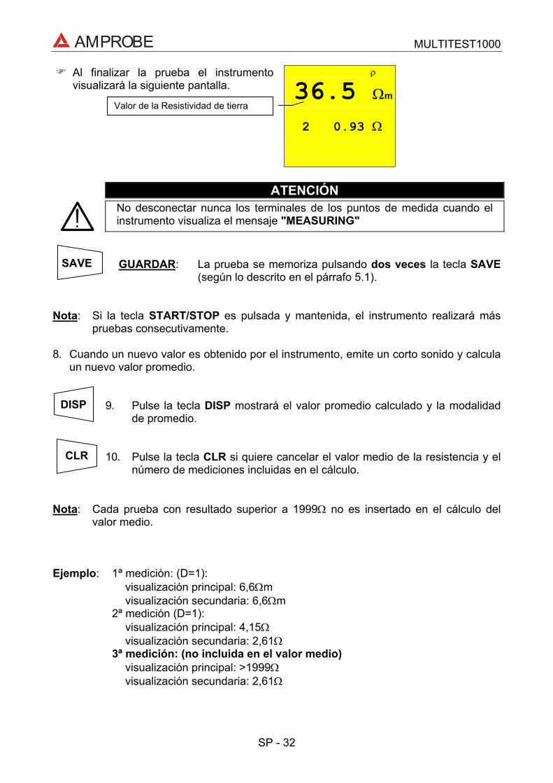
AMPROBE MULTITEST1000
SP - 32
ρ36.5 Ωm
2 0.93 Ω
Al finalizar la prueba el instrumentovisualizará la siguiente pantalla.
ATENCIÓNNo desconectar nunca los terminales de los puntos de medida cuando elinstrumento visualiza el mensaje "MEASURING"
GUARDAR: La prueba se memoriza pulsando dos veces la tecla SAVE(según lo descrito en el párrafo 5.1).
Nota: Si la tecla START/STOP es pulsada y mantenida, el instrumento realizará máspruebas consecutivamente.
8. Cuando un nuevo valor es obtenido por el instrumento, emite un corto sonido y calculaun nuevo valor promedio.
9. Pulse la tecla DISP mostrará el valor promedio calculado y la modalidadde promedio.
10. Pulse la tecla CLR si quiere cancelar el valor medio de la resistencia y elnúmero de mediciones incluidas en el cálculo.
Nota: Cada prueba con resultado superior a 1999Ω no es insertado en el cálculo delvalor medio.
Ejemplo: 1ª medición: (D=1):visualización principal: 6,6Ωmvisualización secundaria: 6,6Ωm
2ª medición (D=1):visualización principal: 4,15Ωvisualización secundaria: 2,61Ω
3ª medición: (no incluida en el valor medio)visualización principal: >1999Ωvisualización secundaria: 2,61Ω
Valor de la Resistividad de tierra
CLR
DISP
SAVE

AMPROBE MULTITEST1000
SP - 33
4.5. SITUACIONES ANOMALAS MODALIDAD EARTH ρ
---- - - c
Si el sistema amperimétrico estácortado, cuando pulsamosSTART/STOP el instrumento no puedemedir la corriente mínima, por tantoaparecerá una pantalla como lasiguiente. Asegúrese que losterminales estén conectadoscorrectamente y que la pica decorriente (conductor azul) no ha sidocolocada en terreno no conductivo. Sies necesario, eche agua alrededor dela pica.
ESTE RESULTADO NO PUEDE SER MEMORIZADO.
31 V
VOL AG
Si el instrumento mide una tensión deinterferencia superior a 30V en elcircuito amperimétrico, no realiza laprueba y aparece la siguiente pantalla.
ESTE RESULTADO NO PUEDE SER MEMORIZADO.
>1999Ω
--- ---
Si la resistencia medida es superior ala escala del instrumento, después depulsar START/STOP el instrumentorealiza la prueba y aparece la siguientepantalla.
rC indica un valoralto deresistencia.
Tensión en el circuito amperimétrico
SAVE
SAVE
1999Ω es el valormáximo deescala medibledel instrumento.

AMPROBE MULTITEST1000
SP - 34
>12.55kΩm
3- - - mΩ
Si la medida de la resistividad es mayorque el siguiente valor 1999x6.28x(distancia entre picas seleccionada),después de pulsar START/STOP elinstrumento realiza la prueba y aparecela siguiente pantalla.
GUARDAR: La prueba se memoriza pulsando dos veces la tecla SAVE(según lo descrito en el párrafo 5.1).
12.55KΩm es elmargen superiordel instrumentocon distancia=3m.
SAVE

AMPROBE MULTITEST1000
SP - 35
5. COMO GUARDAR, RECUPERAR Y BORRAR DATOS GUARDADOSEN MEMORIA
5.1. TECLA GUARDAR: "SAVE"Si los resultados relativos a las pruebas realizadas van a ser guardados debe procedercomo se indica a continuación:
1. Pulse la tecla SAVE una vez.
MEM 3PLA 02
Si la memoria del instrumento no estávacía visualiza la siguiente pantalla.
2. Utilice las teclas y para aumentar o disminuir el valor delparámetro PLA (Posición) relacionada a la medición guardar. Esteparámetro ayuda al usuario a clasificar las pruebas realizadas.
Ejemplo: Si las pruebas se van a llevar a cabo en un edificio, elusuario puede asociar las mediciones realizadas en unasala con un valor dado de parámetro de posición PLA. Deesta forma valores diferentes del parámetro PLAcorresponderán a diferentes salas.
3. Pulse la tecla SAVE de nuevo, el instrumento emite dos pitidos,confirmando que el resultado ha sido guardado.
Pulse la tecla RCL/ESC en cualquier momento para salir del menúmemoria y volver a la medición seleccionada.
Número de memoria en el cual el resultado dela medición será guardado.
Valor del parámetro PLA relacionado con lamedición a guardar.
SAVE
SAVE
RCLESC

AMPROBE MULTITEST1000
SP - 36
5.2. TECLA RECUPERAR: "RCL"Si se quieren consultar los resultados relativos a las pruebas efectuadas y memorizadasproceda del siguiente modo
1. Pulse la tecla RCL/ESC
MEM 3Pla 02
Si la memoria del instrumento no estávacía se visualizará la siguientepantalla.
2. Utilice las teclas y para seleccionar el número de memória que sequiere visualizar.
3. Pulse la tecla DISP mostrará el valor promedio calculado y la modalidadde promedio.
4. Utilice las teclas y para seleccionar el número de localización dememoria a visualizar.
Pulse la tecla RCL/ESC en cualquier momento para salir del menúmemoria y volver a la medición seleccionada.
Número de la posición de memoria en el queserá memorizada la medida.
Valor del parámetro PLA que será asociadocon la medida que será guardada.
RCLESC
DISP
RCLESC
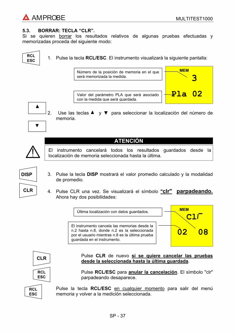
AMPROBE MULTITEST1000
SP - 37
5.3. BORRAR: TECLA “CLR”.Si se quieren borrar los resultados relativos de algunas pruebas efectuadas ymemorizadas proceda del siguiente modo:
1. Pulse la tecla RCL/ESC. El instrumento visualizará la siguiente pantalla:
MEM 3Pla 02
2. Use las teclas y para seleccionar la localización del número dememoria.
ATENCIÓNEl instrumento cancelará todos los resultados guardados desde lalocalización de memoria seleccionada hasta la última.
3. Pulse la tecla DISP mostrará el valor promedio calculado y la modalidadde promedio.
4. Pulse CLR una vez. Se visualizará el símbolo "clr" parpadeando.Ahora hay dos posibilidades:
MEM
Cl02 08
Pulse CLR de nuevo si se quiere cancelar las pruebasdesde la seleccionada hasta la última guardada.
Pulse RCL/ESC para anular la cancelación. El símbolo "clr"parpadeando desaparece.
Pulse la tecla RCL/ESC en cualquier momento para salir del menúmemoria y volver a la medición seleccionada.
Número de la posición de memoria en el queserá memorizada la medida.
Valor del parámetro PLA que será asociadocon la medida que será guardada.
DISP
Última localización con datos guardados.
El instrumento cancela las memorias desde lan.2 hasta n.8, donde n.2 es la seleccionadapor el usuario mientras n.8 es la última pruebaguardada en el instrumento.
RCLESC
CLR
CLR
RCLESC
RCLESC

AMPROBE MULTITEST1000
SP - 38
6. RESETEADO DEL INSTRUMENTO Y DE LOS PARÁMETROSESTÁNDAR
ANTES DE EFECTUAR UN RESETEADO DEL INSTRUMENTO GUARDE TODOS LOSDATOS RELATIVOS A LAS MEDIDAS EFECTUADAS DESCARGÁNDOLOS EN ELPC.
6.1. PROCEDIMIENTO DE RESETEADO1. Pulse las teclas DISP, CLR, RCL y la tecla ON/OFF.2.
esSe visualizará en 5 segundos lasiguiente pantalla, el instrumentoemitirá una señal acústica yvisualiza la pantallacorrespondiente a la funciónseleccionada.
ATENCIÓNcuando se ejecute el procedimiento de Reseteado son borrados todos losdatos residentes en memoria.
6.2. PARÁMETROS ESTÁNDARDespués del RESET los parámetros por defecto programado en el instrumento serán:
Función Parámetro RESET parámetro x defecto
Modalidad AUTOCalibración Offset 0LOWΩ
Modalidad R+/R- TIMER TIMER es programado a 1sModalidad MAN
Tensión de prueba 500VRISOModalidad TIMER TIMER es programado a 60s
EARTH ρ Parámetro DIST DIST = 1
Parámetro PLA P = 1Memoria Estado Memoria 0

AMPROBE MULTITEST1000
SP - 39
7. CONEXIÓN DEL INSTRUMENTO A UN PCLa conexión entre un PC y el instrumento se realiza mediante una conexión al puerto seriemediante el paquete de software.
Antes de efectuar la conexión es necesario que seleccione el puerto COM utilizado para latransmisión. Para ajustar este parámetro inicie el software y consulte “la ayuda” en líneadel programa
ATENCIÓNEl puerto seleccionado NO debe contener otros dispositivos o aplicaciones(ej. ratón, módem, etcétera).
Para transmitir los datos memorizados del instrumento al PC siga el siguienteprocedimiento:
1. Gire el Conmutador en posición RS232.
Proceda como indica la ayuda del programa de gestión para latransmisión de las medidas efectuadas.
SELa comunicación se producirá entre elinstrumento y el PC
Nota: La velocidad de descarga es de: 9600 baud (ver instrucciones del manual delsoftware).

AMPROBE MULTITEST1000
SP - 40
8. MANTENIMIENTO8.1. GENERALIDADES1. El instrumento que Usted ha adquirido es un instrumento de precisión. Durante el uso
y el almacenamiento respete las recomendaciones enumeradas en este manual paraevitar posibles daños o peligros durante el uso.
2. No utilice el instrumento en entornos caracterizados por elevadas tasas de humedad otemperatura. No lo exponga directamente a la luz del sol.
Apague siempre el instrumento después del uso. Si prevé no utilizarlo por un largoperiodo de tiempo quite las baterías para evitar derrame de líquidos que puedanperjudicar los circuitos internos del instrumento.
8.2. CAMBIO DE BATERIASCuando el símbolo es visualizado deberá reemplazar las baterías.
ATENCIÓNSólo técnicos cualificados pueden efectuar esta operación. Antes de efectuaresta operación asegúrese de haber desconectado todos los cables de losterminales de entrada. . El instrumento es capaz de mantener los datosguardados aunque las baterías no estén instaladas.
1. Apague el instrumento con la tecla ON/OFF.2. Desconecte los cables de los terminales de entrada.3. Destornille los tornillos de fijación de la tapa de baterías y saque dicha tapa.4. Reemplace las baterías con 6 nuevas del mismo tipo1. Coloque de nuevo la tapa, fíjela con los tornillos.
8.3. LIMPIEZA DEL INSTRUMENTO
Para la limpieza del instrumento utilice un paño suave y seco. Nunca use paños húmedos,disolventes, agua, etc.

AMPROBE MULTITEST1000
SP - 41
9. ESPECÍFICACIONES TÉCNICAS9.1. CARACTERÍSTICAS TÉCNICASLa precisión está indicada como [% de la lectura ± número de cifras]. Está referida a lassiguientes condiciones atmosféricas listadas en el párrafo 9.2.1.
- Continuidad (LOWΩ)Modalidad de prueba Rango de Medida (Ω) Resolución (Ω) Precisión
0,01 – 19,99 0,01AUTO, R+TIMER, R-TIMER 20,0 – 99,9 0,1 ±(2% lec + 2 dgt)
Corriente de prueba > 200mA CC para R≤5Ω (incluida la calibraciónResolución medida de la corriente 1mATensión en vacío 6V < V0 < 12V
- Resistencia de Aislamiento (RISO)Tensión de prueba (V) Rango de Medida (Ω) Resolución (Ω) Precisión
0,01 - 19,99 0,0120,0 - 49,9 0,1 ±(2% lec + 2 dgt)5050,0 - 99,9 0,1 ±(5% lec + 2 dgt)0,01 - 19,99 0,0120,0 - 99,9 0,1 ±(2% lec + 2 dgt)100
100,0 - 199,9 0,1 ±(5% lec + 2 dgt)0,01 - 19,99 0,0120,0 - 199,9 0,1
200 - 249 1±(2% lec + 2 dgt)250
250 - 499 1 ±(5% lec + 2 dgt)0,01 - 19,99 0,0120,0 - 199,9 0,1
200 - 499 1±(2% lec + 2 dgt)500
500 - 999 1 ±(5% lec + 2 dgt)0,01 - 19,99 0,0120,0 - 199,9 0,1
200 - 999 1±(2% lec + 2 dgt)1000
1000 - 1999 1 ±(5% lec + 2 dgt)
Selección Automática del rango de medidaTensión de vacío Tensión de Prueba nominal –0% +10%Corriente de cortocircuito <6,0mA a 500V programadoCorriente de medida nominal >2,2mA a 500V sobre 230kΩ
1mA a 1KΩ x VNOM (≠ 500 V)
- Tensión ACRango de Medida (V) Resolución (V) Precisión
0 ÷ 460 1 ±(3% lec + 2 dgt)
- Medida de la resistencia de Tierra con el método voltiamperimétricoRango de Medida (Ω) Resolución (Ω) Precisión
0,01 ÷ 19,99 0,0120,0 ÷ 199,9 0,1200 ÷ 1999 1
±(5% lec + 3 dgt)
Corriente de prueba <10mA 77,5HzTensión en vacío <20V RMS

AMPROBE MULTITEST1000
SP - 42
- Medida de resistividad ρRango de Medida (Ω) Resolución (Ωm) Precisión
0.06 ÷ 19,99 Ωm 0,01 Ωm20.0 ÷ 199.9 Ωm 0.1 Ωm200 ÷ 1999 Ωm 1 Ωm
2,00 ÷ 19,99 kΩm 0.01 kΩm20.0 ÷ 125,5 kΩm (*) 0.1 kΩm
±(5% lec + 3 dgt)
(*) con D = 10mCorriente de prueba <10mA 77,5HzTensión en vacío <20V RMS
9.1.1. Normas de seguridadEl instrumento es conforme a las normas: EN 61010-1 + A2(1997)Normas de Producción: IEC61557-1, -2, -4, -6Aislamiento: Clase 2, doble aislamientoNivel de Polución: 2Uso en interiores; altitud max: 2000mCategoría de sobretensión: CAT III 460V∼ T1-T2-T3-T4 / 265V∼ a tierra
9.1.2. Características generalesCaracterísticas generalesDimensiones: 222(L) x 165(La) x 105(H)mmPeso (baterías incluidas): aprox. 1200g
AlimentaciónTipo baterías: 6 baterías 1.5 V – LR6 – AA – AM3 – MN 1500Indicación de baterías descargadas: En el visualizador aparece el símbolo
cuando la tensión de las baterías es demasiadobaja
Duración baterías: Cerca de 40 horas en espera (stand-by) o500 horas en LOWΩ o250 medidas RISO a 500V/500KΩ o1000, prueba secuencia de fases300 Tierra o prueba ρ.
Visualizador: LCD custom 65mmx65mm
Memoria: 350 pruebas
Interfaz: optoaisladas RS232 para descargar datosarchivados al PC.

AMPROBE MULTITEST1000
SP - 43
9.2. AMBIENTE9.2.1. Condiciones ambientales de usoTemperatura de referencia: 23° ± 5°CTemperatura de uso: 0°C ÷ 40 °CHumedad relativa admitida: <80%Temperatura de almacenamiento: -10 ÷ 60 °CHumedad de almacenamiento: <80%
9.2.2. EMCEste instrumento está proyectado conforme las normas EMC en vigor y la compatibilidadhan sido comprobadas relativamente para EN61326-1 (1998) + A1 (1999).
Este instrumento es conforme a las directivas Europeas estándar para CE.
Este instrumento es conforme a los requisitos de la Directiva europea sobre bajatensión 72/23/CEE y de la directiva CEM 89/336/CEE, modificado con las 93/68/CEE.
9.3. ACCESORIOSLos accesorios proporcionados con el instrumento dependen del modelo adquirido deacuerdo a la siguiente tabla. Se denomina accesorio estándar cuando es vendidoconjuntamente con el instrumento.
Accesorios Estándar
Descripción CódigoConjunto con 4 cables (2m), 4 cocodrilos, 2 puntas de prueba MTL-MT1Conjunto con 4 cables (banana-cocodrilo) y 4 picas de tierra GP2-CONPrograma de gestión –Software- www.amprobe.comCable RS232 - Optico C2001Bolsa de transporte CC-MT1
Accesorios opcionales
Descripción CódigoConjunto correa de transporte CN0050

AMPROBE MULTITEST1000
SP - 44
10. ASISTENCIA10.1. CONDICIONES DE GARANTÍA¡Felicidades! Su nuevo instrumento ha sido fabricado de acuerdo a los estándares decalidad y contiene componentes de calidad. Ha sido verificado su correcto funcionamientoen todas sus funciones y comprobado por técnicos cualificados de acuerdo a losestándares establecidos por nuestra empresa.
Su instrumento tiene una garantía limitada contra materiales defectuoso o de fabricaciónde un año desde la fecha de adquisición si en opinión de fabrica el instrumento no ha sidomanipulado.
Si su instrumento se avería debido a materiales defectuosos o de montaje duranteeste periodo de un año, se reparará sin cargo o se reemplazará al usuario. Por favor,tenga a mano su factura con la fecha de compra la cual debe identificar el modelo ynúmero de serie del instrumento y llame al número abajo indicado:
Departamento de ReparacionesATP – Amprobe, TIF, PromaxMiramar, FLPhone: 954-499-5400800-327-5060Fax: 954-499-5454Website: www.amprobe.com
Por favor obtenga el número RMA antes de devolvernos el producto para sureparación.
Fuera de U.S.A. el representante local le prestará asistencia. Los límites de garantíaanteriormente indicados cubren solo la reparación y sustitución del instrumento sinninguna otra obligación implícita.

AMPROBE MULTITEST1000
SP - 45
11. FICHAS PRÁCTICAS PARA LAS VERIFICACIONES ELÉCTRICAS11.1. LOWΩ: MEDIDA DE LA CONTINUIDAD DE LOS CONDUCTORES DE
PROTECCIÓNOBJETIVO DE LA PRUEBAVerificar la continuidad de:a) conductores de protección (PE), conductores equipotenciales principales (EQP),
conductores equipotenciales secundarios (EQS) en los sistemas TT y TN-S.b) conductores de neutro con funciones de conductores de protección (PEN) en el
sistema TN-C.NOTA: Esta prueba instrumental va obviamente precedida por un examen visual que
verifique la existencia de los conductores de protección y equipotenciales de coloramarillo-verde y que las secciones utilizadas estén conformes a lo prescrito porlas Normas.
PARTES DE LA INSTALACIÓN A VERIFICAR
AMPROBE
AMPROBE
Ejemplos de medidas de continuidad de los conductores
Conecte una de laspuntas de prueba ala masa extraña(en este caso es eltubo del agua) y elotro a la instalaciónde tierra elconductor deprotecciónpresente porejemplo utilizandoen la toma FM máscercana.
Conecte una de laspuntas de pruebaal conductor deprotección de latoma y el otro alnodo equipotencialde la instalación detierra.

AMPROBE MULTITEST1000
SP - 46
Verifique la continuidad entre:a) Polos de tierra de todas las tomas de corriente y colector o nodo de tierra.b) Bornes de tierra de los aparatos de clase I (calentadores, etc.) y colectores o nodo
de tierra.c) Masas extrañas principales (tubos de agua, gas, etc.) y colector o nodo de tierra.d) Masas extrañas suplementarias entre ellas y respecto al borne de tierra.
VALORES ADMISIBLESLas Normas CEI 64-8/6 no da indicaciones sobre los valores máximos de resistencia queno deben ser superados para poder declarar positivo el resultado de la prueba decontinuidad.
La CEI 64-8/6 solicita sencillamente al instrumento de medida que indique al operador sila prueba no ha sido efectuada con una corriente de al menos 0,2 A. y una tensión devacío comprendida entre 4 V y 24 V.
Los valores de resistencia se pueden calcular en base a las secciones y a lo largo de losconductores en examen, en cada modo normalmente si se detectan con el instrumentovalores alrededor de algunos ohmios la prueba se puede considerar superada.
11.2. MEDIDA DE LA RESISTENCIA DE AISLAMIENTO DE LA INSTALACIÓNELÉCTRICA (250VCC, 500VCC, 1000VCC)
OBJETIVO DE LA PRUEBAVerificar que la resistencia de aislamiento de la instalación esté conforme a lo previsto delas Normas CEI 64-8/6.
NOTA: Esta prueba instrumental debe ser efectuada con el circuito en examen NOalimentado y con las eventuales cargas desconectadas.
PARTES DE LA INSTALACIÓN A VERIFICAR
a) entre cada conductor activo y el tierra (el conductor de neutro está considerado unconductor activo excepto en el caso de sistemas de alimentación de tipo TN-C dónde esconsiderado parte del tierra (PEN)).Durante esta medida todos los conductores activos pueden ser conectados entre ellos, encaso de que el resultado de la medida no entre en los límites normativos hace falta repetirseparadamente la prueba para cada conductor individual.
b) Entre conductores activos.La norma CEI 64-8/6 recomienda también verificar el aislamiento entre los conductoresactivos cuando eso sea posible (ATENCIÓN).
VALORES ADMISIBLESLos valores de la tensión de medida y de la resistencia mínima de aislamiento puede serobtenido de la tabla (CEI64-8/6 Tab. 61A):

AMPROBE MULTITEST1000
SP - 47
Tensión nominal del circuito (V) Tensión deprueba (V)
Resistencia deAislamiento
(MΩ)
SELV Y PELV * 250 ≥0.250
Hasta 500 V comprendidos, excluidos loscircuitos sobre 500 ≥0.500
Más de 500 V 1000 ≥1.000
* Los términos SELV y PELV reemplazan en la nueva redacción de la normativa las antiguas definiciones"Baja tensión de seguridad o funcional."
Tabla sinóptica de los valores de las tensiones de prueba y relativos valores límite admitidos para lastipologías de prueba más común.

AMPROBE MULTITEST1000
SP - 48
11.3. MEDIDA DE LA RESISTENCIA DE AISLAMIENTO DE LOS SUELOS ENLOCALES DE USO MÉDICO
OBJETIVO DE LA PRUEBAVerificar que el suelo sea realizado con materiales cuya resistencia de aislamiento estéconforme a lo previsto de las normas CEI 64-4 (3.05.03).
PARTES DE LA INSTALACIÓN A VERIFICARLa medida debe ser efectuada entre:a) Dos electrodos colocados de modo que la distancia entre sus bordes sea de unmetro.b) Un electrodo puesto sobre el suelo y el nodo equipotencial.
AMPROBE
Medidas de la resistencia de aislamiento de los suelos en locales de uso médico
Los electrodos deben ser constituidos de una plancha teniendo una superficie de apoyode 20 cm2, de peso igual a 1 Kg (10N), y de un papel secante húmedo (o paño de algodónhumedecido) de igual superficie entre la plancha metálica y el suelo.
La resistencia de aislamiento es representada, sea para las medidas indicadas en "a" seapara las medidas indicadas en "b", de la media de 5 o más pruebas efectuadas enmuchas posiciones a distancia superiores a 1 m de objetos unidos a tierra.
VALORES ADMISIBLESLos valores máximos de la resistencia tan calculada son las siguientes:
- 1 MΩ para medidas efectuadas sobre un suelo nuevo.- 100 MΩ para las verificaciones periódicas efectuadas sucesivamente al primer año de
la realización del suelo y para la verificación periódica cada cuatro años.Todos los valores obtenidos deben ser registrados sobre protocolo de las verificacionesiniciales (64-4 5.1.02).
Prueba a):Conecte una punta deprueba del instrumentosobre el nodoequipotencial y el otrosobre uno de los doselectrodos pruebaposicionado sobre elsuelo a una distanciasuperior a un metro delobjeto conectado atierra.
Prueba b):Conecte las puntas deprueba del instrumentosobre los electrodos deprueba posicionandosobre el suelo a unadistancia reciproca de unmetro entre los bordes.

AMPROBE MULTITEST1000
SP - 49
11.4. VERIFICACIÓN DE LA SEPARACIÓN DE LOS CIRCUITOSObjetivo de la prueba
La prueba, a efectuar en el caso en que la protección se active a través de separación (64-8/6 612.4, SELV o PELV o Separación Eléctrica), tiene que verificar que la resistenciade aislamiento medida sea descrita como a continuación (según el tipo de separación) esconforme a los límites indicados en la tabla relativa a las medidas de aislamiento.
PARTES DE LA INSTALACIÓN A VERIFICAR
• Sistema SELV (Safety Extra Low Voltage):medir la resistencia entre las partes activas del circuito en prueba (separado) ylas partes activas de los otros circuitos.medir la resistencia entre las partes activas del circuito en prueba (separado) y
tierra.
La resistencia debe resultar no inferior a 0,25MΩ con una tensión de prueba de500VCC.
• Sistema PELV (Protective Extra Low Voltage):medir la resistencia entre las partes activas del circuito en prueba (separado) ylas partes activas de los otros circuitos.
La resistencia debe resultar non inferior a 0,25MΩ con una tensión de prueba de250VCC.
• Separación Eléctrica:medir la resistencia entre las partes activas del circuito en prueba (separado) ylas partes activas de los otros circuitos.medir la resistencia entre las partes activas del circuito en prueba (separado) ytierra.
La resistencia debe resultar no inferior a 0,5MΩ con una tensión de prueba de 500VCC y1MΩ con tensión de prueba de 1000VCC.
VALORES ADMISIBLESLa prueba tiene resultado positivo cuando la resistencia de aislamiento presenta valoressuperiores o iguales a los indicados en la tabla indicada en la sección relativa a laspruebas de aislamiento.
Observaciones:
• Sistema SELV: es un sistema de categoría cero o sistema a bajísima tensión deseguridad caracterizado por:
Alimentación: fuente autónoma (ej. Baterías, pequeños grupos electrógenos) o deseguridad (ej. transformadores de seguridad).
Separación de protección respecto a otros sistemas eléctricos (doble aislamiento oreforzado o bien un apantallamiento metálico unido a tierra).
No presenta puntos derivados a tierra (aislado por tierra).
• Sistema PELV: es un sistema de categoría cero o sistema a bajísima tensión deprotección caracterizado por:
Alimentación: fuente autónoma (ej. Baterías, pequeños grupos electrógenos) o deseguridad (ej. transformadores de seguridad).

AMPROBE MULTITEST1000
SP - 50
Separación de protección respecto a otros sistemas eléctricos (doble aislamiento oreforzado o bien un apantallamiento metálico unido a tierra).
Presenta puntos derivados a tierra (aislado por tierra).
• Separación Eléctrica: es un sistema caracterizado por: Alimentación: transformador separador o fuente autónoma con características
equivalentes (ej. grupo motores generadores). Presenta una separación de protección respecto a otros sistemas eléctricos
(aislamiento no inferior al del transformador separador).Presenta una separación de protección respecto a tierra (aislamiento no inferior al deltransformador separador).

AMPROBE MULTITEST1000
SP - 51
EJEMPLO DE VERIFICACIÓN DE SEPARACIONES ENTRE CIRCUITOS ELÉCTRICOS
...And among those other circuits
...Earth installation
Between the activeparts of the separated circuit...
AMPROBE
Medidas de separación entre circuitos en una instalación
Prueba entre laspartes activas ytierra.Conecte unapunta de pruebadel instrumentosobre un de losdos conductoresdel circuitoseparado y elotro sobre elnudoequipotencialEsta prueba sólodebe serefectuada paracircuitos SELV ocon separacióneléctrica.
Prueba entre laspartes activas.conecte unapunta de pruebadel instrumentosobre uno de losdos conductoresdel circuitoseparado y elotro sobre uno delos conductoresde un circuito noseparado.
Transformador de aislamiento o deseguridad que efectúa la separaciónentre los circuitos.

AMPROBE MULTITEST1000
SP - 52
11.5. MEDIDA DE LA RESISTENCIA DE TIERRA, MÉTODO VOLTIAMPERIMÉTRICOTécnica para dispersores de tierra de pequeñas dimensionesSe hace circular una corriente entre el dispersor de tierra en examen y una sonda decorriente posicionada a una distancia del contorno de la instalación de tierra igual a 5veces la diagonal del área que delimita la instalación de tierra. Posicione la sonda detensión la más cercana a la mitad entre el dispersor de tierra y la sonda de corriente, ymedir la tensión entre los dos.
Negro
Verde Azul
Rojo
Medida de resistencia de tierra de pequeñas dimensiones
Técnica para dispersores de tierra de elevadas dimensionesEsta técnica está siempre basada en el método voltiamperimétrico pero se utiliza en casode que resulte dificultoso posicionar la conexión con tierra auxiliar de corriente a unadistancia igual a 5 veces la diagonal del área de la instalación de tierra. Posicione lasonda de corriente a una distancia igual a una vez la diagonal de la instalación de tierra.Para verificar que la sonda de tensión esté situada fuera de las zonas de influencia deldispersor con tierra en prueba efectuar más medidas partiendo con la sonda de tensiónsituada en el punto intermedio entre el dispersor y la sonda de corriente y sucesivamentedesplazando la sonda sea hacia el dispersor de tierra que hacia la sonda de corriente.
Negro
Verde
Rojo
Azul
Medida de resistencia de tierra de elevada dimensiones
Utilizar más picas en paralelo ymojar el terreno circunstante encaso de que el instrumento nologre inyectar la corrientenecesaria para efectuar la pruebaa causa de una elevadaresistencia del terreno.
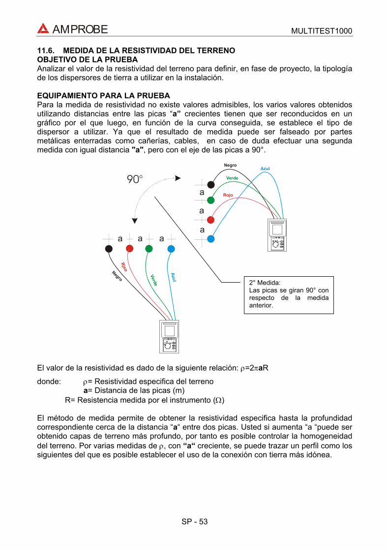
AMPROBE MULTITEST1000
SP - 53
11.6. MEDIDA DE LA RESISTIVIDAD DEL TERRENOOBJETIVO DE LA PRUEBAAnalizar el valor de la resistividad del terreno para definir, en fase de proyecto, la tipologíade los dispersores de tierra a utilizar en la instalación.
EQUIPAMIENTO PARA LA PRUEBAPara la medida de resistividad no existe valores admisibles, los varios valores obtenidosutilizando distancias entre las picas “a” crecientes tienen que ser reconducidos en ungráfico por el que luego, en función de la curva conseguida, se establece el tipo dedispersor a utilizar. Ya que el resultado de medida puede ser falseado por partesmetálicas enterradas como cañerías, cables, en caso de duda efectuar una segundamedida con igual distancia "a", pero con el eje de las picas a 90°.
Negro
Negro
Azul
Azul
Verde
Verde
Rojo
Rjso
a
a aa
a
a
90°
El valor de la resistividad es dado de la siguiente relación: ρ=2πaR
donde: ρ= Resistividad especifica del terrenoa= Distancia de las picas (m)
R= Resistencia medida por el instrumento (Ω)
El método de medida permite de obtener la resistividad especifica hasta la profundidadcorrespondiente cerca de la distancia “a“ entre dos picas. Usted si aumenta “a “puede serobtenido capas de terreno más profundo, por tanto es posible controlar la homogeneidaddel terreno. Por varias medidas de ρ, con “a“ creciente, se puede trazar un perfil como lossiguientes del que es posible establecer el uso de la conexión con tierra más idónea.
2° Medida:Las picas se giran 90° conrespecto de la medidaanterior.
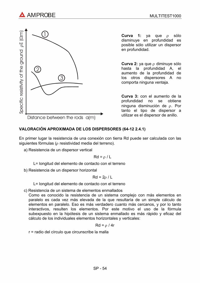
AMPROBE MULTITEST1000
SP - 54
Curva 1: ya que ρ sólodisminuye en profundidad esposible sólo utilizar un dispersoren profundidad.
Curva 2: ya que ρ diminuye sólohasta la profundidad A, elaumento de la profundidad delos otros dispersores A nocomporta ninguna ventaja.
Curva 3: con el aumento de laprofundidad no se obtieneninguna disminución de ρ. Portanto el tipo de dispersor autilizar es el dispersor de anillo.
VALORACIÓN APROXIMADA DE LOS DISPERSORES (64-12 2.4.1)
En primer lugar la resistencia de una conexión con tierra Rd puede ser calculada con lassiguientes fórmulas (ρ resistividad media del terreno).
a) Resistencia de un dispersor vertical
Rd = ρ / LL= longitud del elemento de contacto con el terreno
b) Resistencia de un dispersor horizontal
Rd = 2ρ / LL= longitud del elemento de contacto con el terreno
c) Resistencia de un sistema de elementos enmalladosComo es conocido la resistencia de un sistema complejo con más elementos enparalelo es cada vez más elevada de la que resultaría de un simple cálculo deelementos en paralelo. Eso es más verdadero cuanto más cercanos, y por lo tantointeractivos, resulten los elementos. Por este motivo el uso de la fórmulasubexpuesto en la hipótesis de un sistema enmallado es más rápido y eficaz delcálculo de los individuales elementos horizontales y verticales:
Rd = ρ / 4rr = radio del círculo que circunscribe la malla
Distance between the rods a(m)
Spe
cifi
c re
sistiv
ity o
f the
gro
und
E
(m
)ρ
Ω
3
2
1

Miramar, FL
Phone: 954-499-5400 Fax: 954-499-5454
www.amprobe.com


![Multitest Module - Fiber Optic1].pdf · Digital talk set Fiber-length meter ... with up to 10 remote FOT-930 MaxTester units. ... EXFO’s FTB-3930 MultiTest Module easily and efficiently](https://img.dokumen.tips/doc/110x75/5af767fc7f8b9ae94890181f/multitest-module-fiber-1pdfdigital-talk-set-fiber-length-meter-with-up-to.jpg)