Embed Size (px)
Citation preview

125-5065T Building Technologies 2012-08-06
MS/TP Point Pickup Module
Owner's Manual
Copyright Notice
2 Siemens Industry, Inc. 125-5065T 2012-08-06
Copyright Notice Notice Document information is subject to change without notice by Siemens Industry, Inc. Companies, names, and various data used in examples are fictitious unless otherwise noted. No part of this document may be reproduced or transmitted in any form or by any means, electronic or mechanical, for any purpose, without the express written permission of Siemens Industry, Inc.
Warning This equipment generates, uses, and can radiate radio frequency energy. If equipment is not installed and used in accordance with the instructions manual, it may cause interference to radio communications. Equipment has been tested and found to comply within the limits for a Class B digital device pursuant to Part 15 of the FCC rules. These limits are designed to provide reasonable protection against such interference when operated in a commercial environment. Operation of this equipment in a residential area is likely to cause interference. Residential area equipment users are required to take whatever measures necessary to correct the interference at their own expense.
Service Statement Control devices are combined to make a system. Each control device is mechanical in nature and all mechanical components must be regularly serviced to optimize their operation. Siemens Industry, Inc. branch offices and authorized distributors offer Technical Support Programs that will ensure continuous, trouble-free system performance. For further information, contact your nearest Siemens Industry, Inc. representative. Copyright 2012 by Siemens Industry, Inc.
FCC Regulations The manual for an intentional or unintentional radiator shall caution the user that changes or modifications not expressly approved by the party responsible could void the user’s authority to operate the equipment. For a Class B digital device or peripheral, the instructions furnished the user shall include the following or similar statement, placed in a prominent location in the text of the manual: NOTE: This equipment has been tested and found to comply with the limits for a Class B digital device, pursuant to part 15 of the FCC Rules. These limits are designed to provide reasonable protection against harmful interference in a residential installation. This equipment generates, uses and can radiate radio frequency energy and, if not in-stalled and used in accordance with the instructions, may cause harmful interference to radio communications. However, there is no guarantee that interference will not occur in a particular installation. If this equipment does cause harmful interference to radio or television reception, which can be determined by turning the equipment off and on, the user is encouraged to try to correct the interference by one or more of the following measures: Reorient or relocate the receiving antenna.
Increase the separation between the equipment and receiver.
Copyright Notice
3 Siemens Industry, Inc. 125-5065T 2012-08-06
Connect the equipment into an outlet on a circuit different from that to which the receiver is connected.
To the Reader
Consult the dealer or an experienced radio/TV technician for help.
Your feedback is important to us. If you have comments about this manual, please submit them to: mailto:[email protected]
Credits Staefa and TALON are registered trademarks of Siemens Industry, Inc. Other product or company names mentioned herein may be the trademarks of their respective owners. Printed in USA

5 Siemens Industry, Inc. 125-5065T 2012-08-06
Table of Contents
Product Overview ................................................................................................... 6
Compatibility with Siemens Native BACnet and Third-party Automation Systems .... 7
Board Diagrams ..................................................................................................... 8
Supported Sensor Types ........................................................................................ 9
Specifications ....................................................................................................... 10
Communication (RS-485 Port) .............................................................................. 11
HOA (Hand-Off-Auto) ........................................................................................... 12
DIP Switch Settings .............................................................................................. 13 Baud Rate Settings .................................................................................................. 13
Status LEDs ......................................................................................................... 14
Change of Value Implementation .......................................................................... 15
Accuracy/Resolution ............................................................................................. 15
Wiring ................................................................................................................... 16
I/O Configuration Diagrams .................................................................................. 17
Service Information .............................................................................................. 18 Electrostatic Discharge ............................................................................................ 18 Ordering Replacement Parts ................................................................................... 18 Reinstalling the Mounting Tabs ............................................................................... 18
Glossary ............................................................................................................... 20
Index .................................................................................................................... 21
Product Overview
6 Siemens Industry, Inc. 125-5065T 2012-08-06
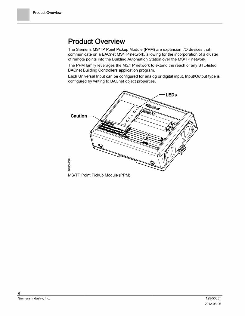
Product Overview The Siemens MS/TP Point Pickup Module (PPM) are expansion I/O devices that communicate on a BACnet MS/TP network, allowing for the incorporation of a cluster of remote points into the Building Automation Station over the MS/TPThe PPM family leverages the MS/TP network to extend the reach of any BTL-listed BACnet Building Controllers application program.
network.
Each Universal Input can be configured for analog or digital input. Input/Output type is configured by writing to BACnet object properties
.
MS/TP
Point Pickup Module (PPM).

Compatibility with Siemens Native BACnet and Third-party Automation Systems
7 Siemens Industry, Inc. 125-5065T 2012-08-06
Compatibility with Siemens Native BACnet and Third-party Automation Systems MS/TP PPM devices are BTL listed as application specific controllers (ASC) and are compatible with other BTL-listed devices, including all Siemens BACnet building controllers and operator workstations. All firmware revisions of Siemens Compact and Modular BACnet building controllers support the MS/TP PPM family, and Firmware Revision 3.2.2 and later also adds support for U-COV (unsolicited change of value). Siemens operator workstation Revision 3.11 and later provide System Profile icons representing MS/TP PPM devices. Siemens BACnet operator workstations with BOB (BACnet Object Browser , available with Rev 3.7 and later) provide the ability to modify the MS/TP PPM’s custom default device ID, device name and COV increment.
NOTE: BACnet systems consist of devices that communicate using the BACnet protocol, and are therefore interoperable with other BACnet products to a certain extent. Note that interoperability is always dependent on the implementation by the manufacturer in addition to how the device is actually applied in the field. Only commonly implemented features will work correctly. Carefully study PICS and BTL for interoperability when evaluating for use in a mixed manufacturer BACnet system.
Board Diagrams
8 Siemens Industry, Inc. 125-5065T 2012-08-06
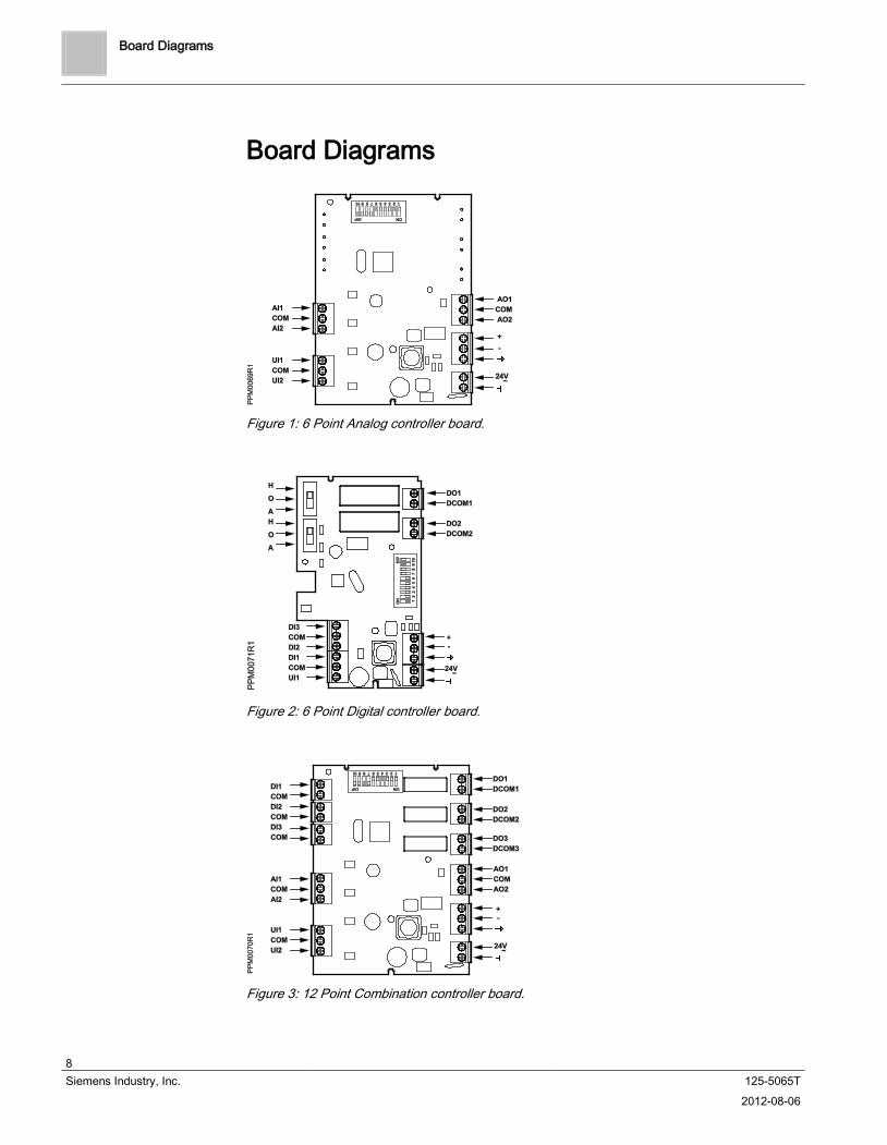
Board Diagrams
Figure 1:
6 Point Analog controller board.
Figure 2:
6 Point Digital controller board.
Figure 3:
12 Point Combination controller board.
Supported Sensor Types
9 Siemens Industry, Inc. 125-5065T 2012-08-06
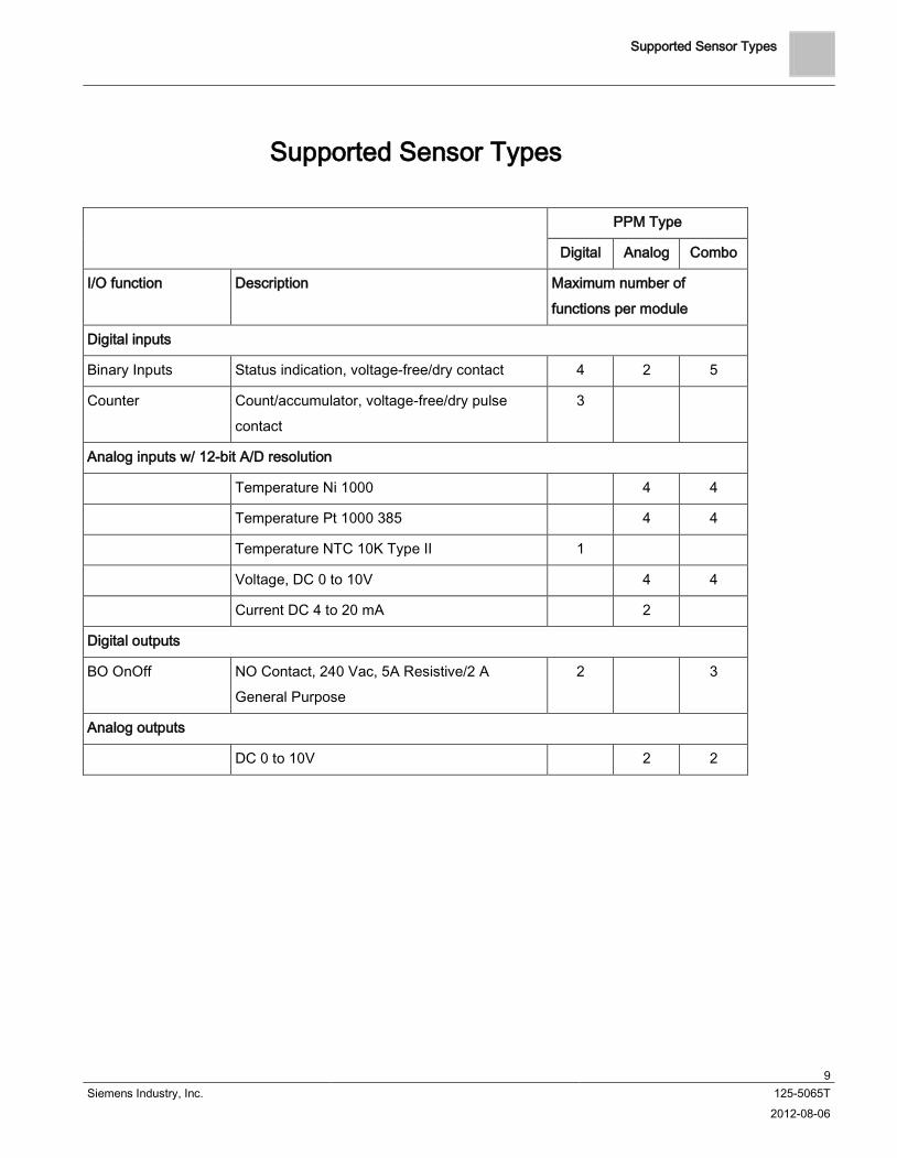
Supported Sensor Types
PPM Type
Digital Analog Combo
I/O function Description Maximum number of functions per module
Digital inputs
Binary Inputs Status indication, voltage-free/dry contact 4 2 5
Counter Count/accumulator, voltage-free/dry pulse contact
3
Analog inputs w/ 12-bit A/D resolution
Temperature Ni 1000 4 4
Temperature Pt 1000 385 4 4
Temperature NTC 10K Type II 1
Voltage, DC 0 to 10V 4 4
Current DC 4 to 20 mA 2
Digital outputs
BO OnOff NO Contact, 240 Vac, 5A Resistive/2 A General Purpose
2 3
Analog outputs
DC 0 to 10V 2 2
Communication (RS-485 Port)
10 Siemens Industry, Inc. 125-5065T 2012-08-06
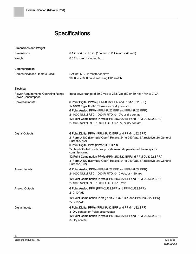
Specifications
Dimensions
Dimensions and Weight
6.1 in. x 4.5 x 1.5 in. (154 mm x 114.4 mm x 40 mm)
Weight 0.85 lb max. including box
Communication
Communications Remote Local BACnet MS/TP master or slave9600 to 76800 baud set using DIP switch
Power Requirements Operating Range Power Consumption
Electrical
Input power range of 19.2 Vac to 28.8 Vac (50 or 60 Hz) 4 VA to 7 VA
Universal Inputs 6 Point Digital PPMs (PPM-1U32.BPR and PPM-1U32.BPF1- 10KΩ Type II NTC Thermistor or dry contact
)
6 Point Analog PPMs (PPM-2U22.BPF and PPM-2U22.BPR2- 1000 Nickel RTD, 1000 Pt RTD, 0-10V, or dry contact
)
12 Point Combination PPMs (PPM-2U3322.BPFand PPM-2U3322.BPR2- 1000 Nickel RTD, 1000 Pt RTD, 0-10V, or dry contact
)
Digital Outputs 6 Point Digital PPMs (PPM-1U32.BPR and PPM-1U32.BPF2- Form A NO (Normally Open) Relays. 24 to 240 Vac, 5A resistive, 2A General Purpose, 5(2)
)
2- Hand-Off-Auto switches provide manual operation of the relays for commissioning
6 Point Digital PPM (PPM-1U32.BPR)
12 Point Combination PPMs (PPM-2U3322.BPFand PPM-2U3322.BPR3- Form A NO (Normally Open) Relays. 24 to 240 Vac, 5A resistive, 2A General Purpose, 5(2)
)
Analog Inputs 6 Point Analog PPMs (PPM-2U22.BPF and PPM-2U22.BPR2- 1000 Nickel RTD, 1000 Pt RTD, 0-10 Vdc, or 4-20 mA
)
12 Point Combination PPMs (PPM-2U3322.BPFand PPM-2U3322.BPR2- 1000 Nickel RTD, 1000 Pt RTD, 0-10 Vdc
)
Analog Outputs 6 Point Analog PPM (PPM-2U22.BPF and PPM-2U22.BPR2- 0-10 Vdc
)
12 Point Combination PPM (PPM-2U3322.BPFand PPM-2U3322.BPR2- 0-10 Vdc
)
Digital Inputs 6 Point Digital PPMs (PPM-1U32.BPR and PPM-1U32.BPF) 3- Dry contact or Pulse accumulator 12 Point Combination PPMs (PPM-2U3322.BPFand PPM-2U3322.BPR3- Dry contact
)
Communication (RS-485 Port)
11 Siemens Industry, Inc. 125-5065T 2012-08-06
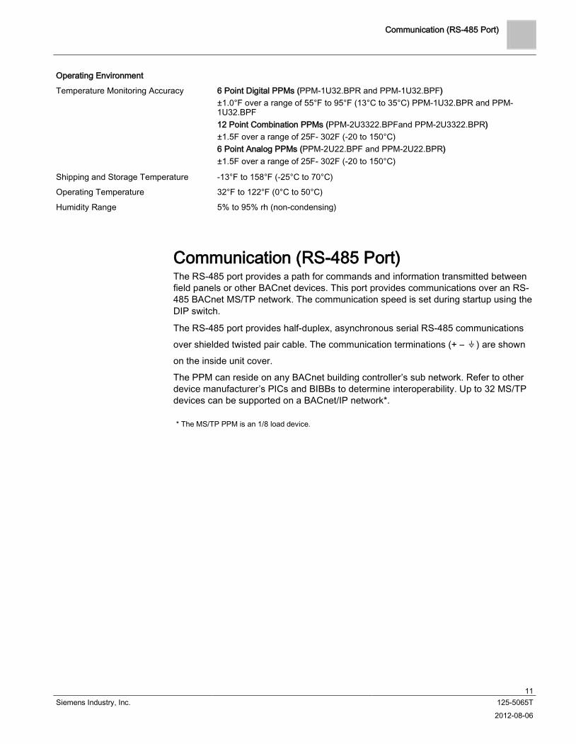
Temperature Monitoring Accuracy
Operating Environment
6 Point Digital PPMs (PPM-1U32.BPR and PPM-1U32.BPF) ±1.0°F over a range of 55°F to 95°F (13°C to 35°C) PPM-1U32.BPR and PPM-1U32.BPF 12 Point Combination PPMs (PPM-2U3322.BPFand PPM-2U3322.BPR±1.5F over a range of 25F- 302F (-20 to 150°C)
)
6 Point Analog PPMs (PPM-2U22.BPF and PPM-2U22.BPR±1.5F over a range of 25F- 302F (-20 to 150°C)
)
Shipping and Storage Temperature -13°F to 158°F (-25°C to 70°C)
Operating Temperature 32°F to 122°F (0°C to 50°C)
Humidity Range 5% to 95% rh (non-condensing)
Communication (RS-485 Port) The RS-485 port provides a path for commands and information transmitted between field panels or other BACnet devices. This port provides communications over an RS-485 BACnet MS/TP
The RS-485 port provides half-duplex, asynchronous serial RS-485 communications over shielded twisted pair cable. The communication terminations (+ –
network. The communication speed is set during startup using the DIP switch.
) are shown on the inside unit cover. The PPM can reside on any BACnet building controller’s sub network. Refer to other device manufacturer’s PICs and BIBBs to determine interoperability. Up to 32 MS/TP devices can be supported on a BACnet/IP network*.
* The MS/TP PPM is an 1/8 load device.

HOA (Hand-Off-Auto)
12 Siemens Industry, Inc. 125-5065T 2012-08-06
HOA (Hand-Off-Auto) Hand-Off-Auto (HOA) switches are available only for the Digital MS/TP PPM (PPM-1U32.BPR). These switches can be used for commissioning. In the H position, the digital output is ON, in the O position the digital output is OFF. For system control the switch must be set to the A
position.
Figure 4:
Hand-Off_Auto Switches (Digital Only).

DIP Switch Settings Baud Rate Settings
13 Siemens Industry, Inc. 125-5065T 2012-08-06
DIP Switch Settings DIP Switches 1 through 8 are used to set the MAC address. Switches 9 and 10 are used to set the communication speed (baud rate).
Figure 5:
DIP Switches.
Baud Rate Settings Use DIP Switches 9 and 10 to set the device’s communication speed (baud rate).
Baud Rate Switch 9 Switch 10
9600 OFF OFF
19200 OFF ON
38400 ON OFF
76800 ON ON
Accuracy/Resolution
14 Siemens Industry, Inc. 125-5065T 2012-08-06
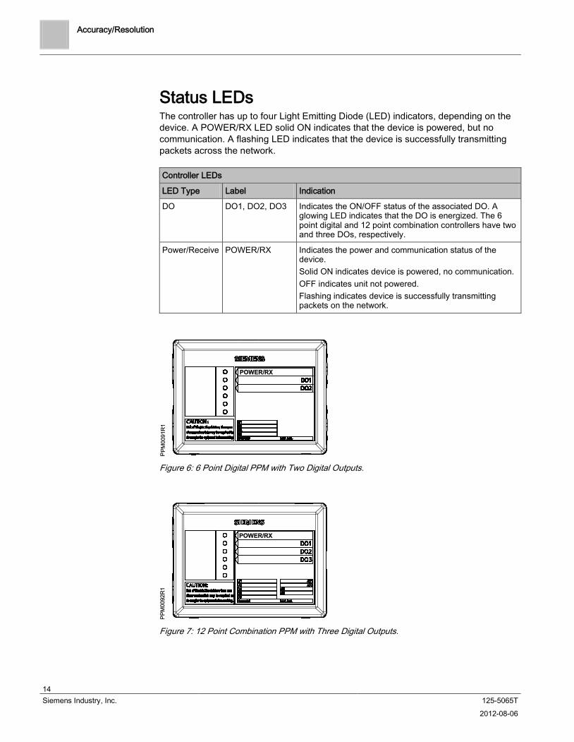
Status LEDs The controller has up to four Light Emitting Diode (LED) indicators, depending on the device. A POWER/RX LED solid ON indicates that the device is powered, but no communication. A flashing LED indicates that the device is successfully transmitting packets across the network.
Controller LEDs
LED Type Label Indication
DO DO1, DO2, DO3 Indicates the ON/OFF status of the associated DO. A glowing LED indicates that the DO is energized. The 6 point digital and 12 point combination controllers have two and three DOs, respectively.
Power/Receive POWER/RX Indicates the power and communication status of the device. Solid ON indicates device is powered, no communication. OFF indicates unit not powered. Flashing indicates device is successfully transmitting packets on the network.
Figure 6:
6 Point Digital PPM with Two Digital Outputs.
Figure 7:
12 Point Combination PPM with Three Digital Outputs.

Accuracy/Resolution
15 Siemens Industry, Inc. 125-5065T 2012-08-06
Figure 8:
6 Point Analog PPM without DOs.
Change of Value Implementation Change of Value (COV) on the MS/TP PPM is implemented as follows: Broadcast only on the same network as the initiated device. (Not a global
broadcast) This reduces network traffic to only the local MS/TP network in which the PPM with COV’s resides.
COVs can be turned on or off by writing to binary output 80 (Enable COV). The COV limit is user configurable over the MSTP network, and can be adjusted down for better resolution or up for less network traffic.
Default COV limit is 0.5 for AI’s and AO’s; thermistor (NTC10K, Ni1000& Pt1000) 0.5F; 0-10V or 4-20 mA 1%.
MaxInfoFrames is configurable from 1 to 15; the default is 12. This variable specifies the maximum number of information frames (COVs) the node may send before it must pass the token.
Accuracy/Resolution
Signal Accuracy Resolution Range
Ni1000 32.9°F (0.5°C) 32.2°F (0.1°C) -4 – 302°F (-20°C – 150°C)
Pt1000 32.9°F 0.5°C 32.2°F (0.1°C) -4 – 302°F (-20°C – 150°C)
NTC10k 33.0°F(0.56°C) 32.3°F(0.14°C) -13 –165.2°F(-25℃ – 74°C)
4 to 20 mA 200uA 100uA 4 to 20 mA
0 to 10V input 100mV(1%) 50mV 0 to 10V
0 to 10V output 100mV(1%) 30mV 0 to 10V
Table 1:
Wiring
16 Siemens Industry, Inc. 125-5065T 2012-08-06
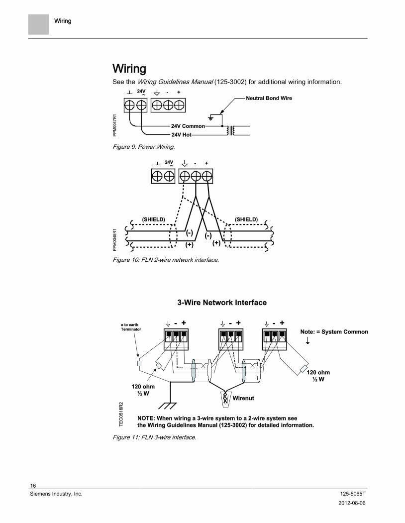
Wiring See the Wiring Guidelines Manual (125-3002) for additional wiring information.
Figure 9: Power Wiring.
Figure 10: FLN 2-wire network interface.
Figure 11:
FLN 3-wire interface.

I/O Configuration Diagrams
17 Siemens Industry, Inc. 125-5065T 2012-08-06
I/O Configuration Diagrams
Figure 12: AI/DI wiring for 6 point digital.
Figure 13:
DO wiring for wiring for 6 point digital.
Figure 14: Analog input wiring.
Figure 15: Universal input wiring.
Figure 16:
Analog output wiring.

Service Information Electrostatic Discharge
18 Siemens Industry, Inc. 125-5065T 2012-08-06
Service Information This section describes corrective measures you can take if you encounter a problem with an MS/TP PPM device. If you encounter a symptom or a problem not covered in this manual, contact your Siemens Solution Partner, Authorized TALON Dealer
.
NOTE: When removing power to a controller to perform maintenance or service, make sure that the person in charge of the facility is aware of this and that appropriate steps are taken to keep the building in control.
NOTE: When troubleshooting, record the problem and what actions were performed immediately before the problem occurred. Being able to describe the problem in detail is important should you need assistance from your local Siemens Solution Partner, Authorized TALON Dealer.
To view the status of the MS/TP PPM device and to call up reports for troubleshooting, you can use an operator's terminal and the operator interface or a TALON View workstation. For more information, see the following documentation: TALON Firmware User's Manual (588-580It is good practice to back up the
). MS/TP PPM
While performing the troubleshooting procedures outlined in this manual, you may want to refer to the
device database routinely and whenever changes are made to the database or new equipment is added.
TALON Wiring Guidelines Manual (588-581
).
Electrostatic Discharge An electrostatic discharge (ESD) wrist strap is generally not required when installing or servicing an MS/TP
PPM. However, if the device is installed in a very dry environment where a high static discharge is likely, an ESD wrist strap is recommended.
Ordering Replacement Parts If a MS/TP
PPM is not operating correctly, it should be replaced.
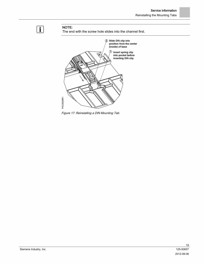
Reinstalling the Mounting Tabs Do the following to reinstall a DIN mounting tab:
1. Place the wire spring clip into the pocket in the channel for the mounting tab.
2.
Make sure the mounting tab is face down. Working from the center (inside) of the base, slide the mounting tab into the channel. (See the following figure.)
Service Information Reinstalling the Mounting Tabs
19 Siemens Industry, Inc. 125-5065T 2012-08-06
NOTE: The end with the screw hole slides into the channel first.
Figure 17: Reinstalling a DIN Mounting Tab.
Glossary
20 Siemens Industry, Inc. 125-5065T 2012-08-06
Glossary
analog input (AI) point Point that receives a signal that represents a condition which has more than two states. For example, flow rate sensors (water or air), temperature sensors (room or duct), pressure sensors (static or velocity), and humidity sensors (room, duct or outdoor).
analog output (AO) point Point that sends a signal to command equipment which has more than two states. For example, damper or valve positioners, fan inlet vane controllers, motor controllers, or electric heater controllers.
BACnet Data communication protocol for Building Automation and Control networks, ANSI/ASHRAE Standard 135-1995. BACnet allows devices from multiple manufacturers to work together.
BACnet Object Browser An application that allows you to browse Siemens BACnet devices and objects and third-party BACnet devices and objects for diagnostic purposes.
BIBB BACnet Interoperatibility Building Blocks. Collections of one or more BACnet services that function to define the interoperational capabilities of a BACnet device. For more information, see the Building Automation and Control Networks, ANSI/ASHRAE Standard 135-2004.
change-of-value (COV) Point trending method where each change in a point's value, based on a pre-defined limit, is recorded.
digital input (DI) point Point that receives a two-state signal such as ON/OFF and OPEN/CLOSE. For example, low temperature detectors, differential pressure switches, flow proof switches, and door closures.
digital output (DO) point Point that sends a two-state signal such as ON/OFF and OPEN/CLOSE. For example, two-speed fan motor starters, two-position valves and dampers, pump motor starters, lighting switches, and chiller and boiler switches.
HAND-OFF-AUTO (HOA) switches Manually operated control switches located on the face of HOA equipped MECs and point expansion modules that enable digital output points to be manually placed into HAND (ON), OFF, or AUTO control. Analog outputs can be placed into AUTO and nine manual control positions.
light emitting diode (1) Solid state device that gives off light when electricity passes through it. (2) Display applications are classified either as low information content (where a limited amount of information is being displayed, refresh rates are slow, and the nature of information being displayed is predictable), or as high information content (where the opposite conditions apply). Broadly speaking LEDs, ELs, and VFDs are best suited to the former, while plasma and all types of LCDs are appropriate for the latter.
Protocol Implementation Conformance Statement (PICS)
Available from building automation control vendors, a PICS documents such things as supported conformance class, functional groups, standard application services, standard object types, data link layer options, character sets, and any special functionality built into the protocol.

Index
21 Siemens Industry, Inc. 125-5065T 2012-08-06
Index A accuracy/resolution, 15
B baud rate settings, 13 board diagrams, 8
C Change of Value implementation, 15 communication, 11
with BACnet devicescompatibility
, 7 with Siemens operator workstations, 7
D
boarddiagrams
, 8 wiring, 16, 17
DIP switch, 13
E electrostatic discharge (ESD), 18
H Hand-Off-Auto switches, 12
I I/O configuration diagrams, 17
N
communicationnetwork
, 11 compatibility, 7 wiring, 16
O overview, 6
S service information, 18
electrostatic discharge (ESD), 18 reinstalling the mounting tabs, 18
baud ratesettings
, 13 DIP switch, 13 Hand-Off-Auto, 12
specifications, 10 status LEDs, 14
DIPswitches
, 13 Hand-Off-Auto, 12
W
I/O configurationwiring
, 17 network, 16 power, 16

Issued by Siemens Industry, Inc. Building Technologies Division 1000 Deerfield Pkwy Buffalo Grove IL 60089 Tel. +1 847-215-1000
© 2012 Copyright Siemens Industry, Inc. Technical specifications and availability subject to change without notice.
Document ID 125-5065T 125-5065T(AA) Edition 2012-08-06