Embed Size (px)
Citation preview

MSI-mx/RxMSI-mxE/Rx
Modular Safety Interface
C O N N E C T I N G A N D O P E R A T I N G I N S T R U C T I O N S
O r i g i n a l I n s t r u c t i o n s
6036
01 -
201
1/05
S u
bjec
t to
cha
nge
with
out p
rior n
otic
e

2 MSI-mx(E)/Rx
DE
UT
SC
HE
NG
LIS
CH
FR
AN
ZÖ
SIS
CH
ITA
LIE
NIS
CH
SP
AN
ISC
H
Notes on connecting and operating instructions
These connecting and operating instructions contain information on the proper use of MSI Safety Interfaces in accordance with its intended purpose.
All the information contained herein, in particular the safety notes, need to be carefully observed.
Notes regarding safety and warnings are marked by this symbol .
These connecting and operating instructions must be stored carefully. It must be available for the entire operating time of the MSI Safety Interfaces.
The Leuze electronic GmbH + Co. KG is not liable for damages caused by improper use. Acquaintance with these instructions is an element of the knowledge required for proper use.
© Reprints and reproduction, in whole or in part, are permitted only with the explicit permission of
Leuze electronic GmbH + Co. KG In der Braike 1 D-73277 Owen - Teck / Germany Phone +49 (0) 7021 / 573-0 Fax +49 (0) 7021 / 573-199 [email protected] www.leuze.com

MSI-mx(E)/Rx 3
SP
AN
ISC
HIT
AL
IEN
ISC
HF
RA
NZ
ÖS
ISC
HE
NG
LIS
CH
DE
UT
SC
H
Contents
1 System Overview and Range of Applications . . . . . . . . . . . . . . . . . . . 6
1.1 General Information . . . . . . . . . . . . . . . . . . . . . . . . . . . . . . . . . . . . . . . . . . 61.2 Approvals . . . . . . . . . . . . . . . . . . . . . . . . . . . . . . . . . . . . . . . . . . . . . . . . . . 61.3 Terms used . . . . . . . . . . . . . . . . . . . . . . . . . . . . . . . . . . . . . . . . . . . . . . . . 71.4 Nomenclature MSI-mx(E)/Rx . . . . . . . . . . . . . . . . . . . . . . . . . . . . . . . . . . . 8
2 Safety . . . . . . . . . . . . . . . . . . . . . . . . . . . . . . . . . . . . . . . . . . . . . . . . . . . . 9
2.1 Approved purpose and foreseeable improper operation . . . . . . . . . . . . . . 92.1.1 Proper use . . . . . . . . . . . . . . . . . . . . . . . . . . . . . . . . . . . . . . . . . . . . . . . . 102.1.2 Foreseeable misuse . . . . . . . . . . . . . . . . . . . . . . . . . . . . . . . . . . . . . . . . 122.2 Competent personnel . . . . . . . . . . . . . . . . . . . . . . . . . . . . . . . . . . . . . . . 122.3 Responsibility for safety . . . . . . . . . . . . . . . . . . . . . . . . . . . . . . . . . . . . . . 122.4 Exemption of liability . . . . . . . . . . . . . . . . . . . . . . . . . . . . . . . . . . . . . . . . 13
2.5 Emergency STOP buttons to be connected . . . . . . . . . . . . . . . . . . . . . . 142.6 Additional Safety Precautions for the Special Function "Muting" . . . . . . . 14
3 System Configuration and Functions . . . . . . . . . . . . . . . . . . . . . . . . . 153.1 System Configuration . . . . . . . . . . . . . . . . . . . . . . . . . . . . . . . . . . . . . . . 15
3.2 DIP Switch Settings . . . . . . . . . . . . . . . . . . . . . . . . . . . . . . . . . . . . . . . . . 153.2.1 DIP Switch Settings for the MSI-mx Module . . . . . . . . . . . . . . . . . . . . . . 153.2.2 DIP Switch Settings for the I/O-mx Module . . . . . . . . . . . . . . . . . . . . . . . 163.2.3 DIP Switch Settings for the Rx Output . . . . . . . . . . . . . . . . . . . . . . . . . . . 173.3 Operating Modes and Functions . . . . . . . . . . . . . . . . . . . . . . . . . . . . . . . 183.3.1 Operating Modes Interlocking Functions and External Device
Monitoring . . . . . . . . . . . . . . . . . . . . . . . . . . . . . . . . . . . . . . . . . . . . . . . . 183.3.1.1 Operating Mode: With Start/Restart Interlock – With Dynamic External
Device Monitoring . . . . . . . . . . . . . . . . . . . . . . . . . . . . . . . . . . . . . . . . . . 193.3.1.2 Operating Mode: With Start/Restart Interlock – With Static External Device
Monitoring . . . . . . . . . . . . . . . . . . . . . . . . . . . . . . . . . . . . . . . . . . . . . . . . 203.3.1.3 Operating Mode: With Start/Restart Interlock – Without External Device
Monitoring . . . . . . . . . . . . . . . . . . . . . . . . . . . . . . . . . . . . . . . . . . . . . . . . 20
3.3.1.4 Operating Mode: Without Start/Restart Interlock – Without External Device
Monitoring . . . . . . . . . . . . . . . . . . . . . . . . . . . . . . . . . . . . . . . . . . . . . . . . 213.3.1.5 Operating Mode: With Start/Without Restart Interlock – Without External
Device Monitoring . . . . . . . . . . . . . . . . . . . . . . . . . . . . . . . . . . . . . . . . . . 213.3.2 Muting Functions . . . . . . . . . . . . . . . . . . . . . . . . . . . . . . . . . . . . . . . . . . . 223.3.2.1 Sequential Muting, Muting sensors at M1 to M4 . . . . . . . . . . . . . . . . . . . 223.3.2.2 Parallel Muting (2,5 s), Muting sensors M2 and M3 . . . . . . . . . . . . . . . . 22
3.3.2.3 Parallel Double Muting (dual-range muting) using M2 and M3, M1 and M4 . . . . . . . . . . . . . . . . . . . . . . . . . . . . . . . . . . . . . . . . . . . . . . . . . . 22
3.3.2.4 Testable and Non-Testable Muting Sensors . . . . . . . . . . . . . . . . . . . . . . 233.3.2.5 Muting Display Function . . . . . . . . . . . . . . . . . . . . . . . . . . . . . . . . . . . . . 243.3.2.6 Muting Restart while transported goods are located in the muting area . 243.3.2.7 10-Minute Muting Time-Limit . . . . . . . . . . . . . . . . . . . . . . . . . . . . . . . . . 25
3.3.2.8 Example: Sequential Muting with Non-Testable Muting Sensors . . . . . 263.3.2.9 Example: Sequential Muting with Testable Muting Sensors . . . . . . . . . 273.3.2.10 Example: Parallel Muting (2.5 s) with Non-Testable Muting Sensors . . 283.3.2.11 Example: Parallel Muting (2.5 s) with Testable Muting Sensors . . . . . . 293.3.2.12 Example: Parallel Double Muting with Non-Testable Muting Sensors . . 30
3.3.3 Protective Door Monitoring . . . . . . . . . . . . . . . . . . . . . . . . . . . . . . . . . . . 313.3.4 Relay Operation Monitoring Function Pre-failure Message in
/Rx Versions . . . . . . . . . . . . . . . . . . . . . . . . . . . . . . . . . . . . . . . . . . . . . . 313.4 Displays . . . . . . . . . . . . . . . . . . . . . . . . . . . . . . . . . . . . . . . . . . . . . . . . . 323.5 Status Outputs . . . . . . . . . . . . . . . . . . . . . . . . . . . . . . . . . . . . . . . . . . . . 343.6 Diagnosis System . . . . . . . . . . . . . . . . . . . . . . . . . . . . . . . . . . . . . . . . . . 36
4 Electrical Connection . . . . . . . . . . . . . . . . . . . . . . . . . . . . . . . . . . . . . . 374.1 Installation Regulations . . . . . . . . . . . . . . . . . . . . . . . . . . . . . . . . . . . . . . 374.2 Power Supply Requirements . . . . . . . . . . . . . . . . . . . . . . . . . . . . . . . . . 374.3 Connecting AOPDs, Type 4 or Type 2 . . . . . . . . . . . . . . . . . . . . . . . . . . 374.4 Connecting Machine Controls . . . . . . . . . . . . . . . . . . . . . . . . . . . . . . . . . 41
5 Connection Circuit Diagram, Examples . . . . . . . . . . . . . . . . . . . . . . . 42

4 MSI-mx(E)/Rx
DE
UT
SC
HE
NG
LIS
CH
FR
AN
ZÖ
SIS
CH
ITA
LIE
NIS
CH
SP
AN
ISC
H
6 Technical Data and Ordering Information . . . . . . . . . . . . . . . . . . . . . 446.1 MSI-mx(E)/Rx . . . . . . . . . . . . . . . . . . . . . . . . . . . . . . . . . . . . . . . . . . . . . 446.2 /Rx-Output . . . . . . . . . . . . . . . . . . . . . . . . . . . . . . . . . . . . . . . . . . . . . . . . 47
6.3 Dimensional Drawing . . . . . . . . . . . . . . . . . . . . . . . . . . . . . . . . . . . . . . . 48
6.4 Ordering Information . . . . . . . . . . . . . . . . . . . . . . . . . . . . . . . . . . . . . . . . 49
7 EC Declaration of Conformity . . . . . . . . . . . . . . . . . . . . . . . . . . . . . . . 50
MSI-mx(E)/Rx 5
SP
AN
ISC
HIT
AL
IEN
ISC
HF
RA
NZ
ÖS
ISC
HE
NG
LIS
CH
DE
UT
SC
H
6 MSI-mx(E)/Rx
DE
UT
SC
HE
NG
LIS
CH
FR
AN
ZÖ
SIS
CH
ITA
LIE
NIS
CH
SP
AN
ISC
H
1 System Overview and Range of Applications
1.1 General Information
The Modular Safety Interface (MSI) serves as a linkbetween one or more active optoelectronic protectivedevices (AOPD), Type 2, Type 3 or Type 4, and themachine controls. All MSI safety components includestart/restart interlock and external device monitoringfunctions that can be activated and deactivated. They arealso equipped with a series of status outputs and LEDdisplays as well as a diagnosis interface to a PC.
In addition, MSI-mx(E)/Rx offers a selection of mutingfunctions to suppress the protective function of an AOPD,e.g. during the time material is transported through thesensing field . Special safety regulations for cyclicaloperation and muting are described in SectionChapter 2.6 below.
Leuze electronic offers a variety of additional MSI SafetyInterfaces with standard or special functions, for examplewith cycling mode (controlling a machine by the AOPD’ssensing field).
All MSI safety modules are equipped with relay outputs.The MSI x-variants allow the additional connection ofsafety interlocks or emergency-stop buttons regardingcategory 4.
All information also applies to UL compliant version MSI-mx(E)/Rx, provided that nothing to the contrary isstated
1.2 Approvals
EuropeEC Type ExaminationDIN EN ISO 13849-1/2GS-ET-20 "Safety relays"IFAInstitut für Arbeitsschutz der Deutschen Gesetzlichen UnfallversicherungD-53757 Sankt Augustin

MSI-mx(E)/Rx 7
SP
AN
ISC
HIT
AL
IEN
ISC
HF
RA
NZ
ÖS
ISC
HE
NG
LIS
CH
DE
UT
SC
H
1.3 Terms used
1.1-2.2 State Output Safety Switches
AOPD Active Optoelectronic Protective Device
Diagn. Diagnosis Function
EDM External Device Monitoring
ESPE Electro-sensitive Protecting Equipment
Fault Relay Fault
I/O-m Module Extended Input/Output Modul
Lamp Warn. Muting Indicator Failure Warning
Locked Start/Restart Interlock active
M1 - M4 Muting Input 1 - 4
N.C. Normal Closed Contact
N.O. Normal Open Contact
OSSD Safety-Related Switching Output
Reset Start/Restart Interlock Initiator
RS 232 Interface RS 232
S1 - S4 Safety input 1 - 4
S1 & S2 S3 & S4
Indication protected fields free/interrupted
SSD Secondary Switching Device(switches to ON state when the MSI is rea-dy for operation)
Test Test Signal Outputs
T1, T2 Test signal output 1, 2
Warn. (I/O-mx Module)
Warning Muting indicator defective
Warn. (Rx Modu-le)
Warning (preset number of switching ope-rations exceeded)

8 MSI-mx(E)/Rx
DE
UT
SC
HE
NG
LIS
CH
FR
AN
ZÖ
SIS
CH
ITA
LIE
NIS
CH
SP
AN
ISC
H
1.4 Nomenclature MSI-mx(E)/Rx
MSI Modular Safety Interface
m with muting function
x extended functionsThe extended version offers the following standard functions for either 2 AOPDs, Type 4, or up to 4 AOPDs, Type 2: – Start/restart interlock– External device monitoring– Diagnosis functionand the following special functions for 1 AOPD Type 4 or 1 AOPD Type 2:– Sequential muting– Parallel muting (2.5 s)or for 2 AOPD either Type 4 or Type 2– Parallel double muting additionally– Possible connection of safety switches (e.g. door switches)– Displays and status outputs for guard and muting operation
/Rx Relay output with extended functions:– two normal open safety contacts, OSSD 1 and OSSD 2– one normal closed safety contact OSSD 3 – one normal open contact "MSI readiness” SSDAdditional special function:– relay operation monitoring with pre-failure message
(E) UL compliant version– additional housing for convection

MSI-mx(E)/Rx 9
SP
AN
ISC
HIT
AL
IEN
ISC
HF
RA
NZ
ÖS
ISC
HE
NG
LIS
CH
DE
UT
SC
H
2 Safety
Before using the Safety Interface Device, a risk evalua-tion must be performed according to valid standards (e.g. ISO 14121, EN ISO 12100-1, ISO 13849-1, IEC 61508, EN 62061). The result of the risk assessment determines the required safety level of the Safety Interface Device (see table in chapter 2.1.1). For mounting, operating and testing, document "MSI-mx(E)/Rx Modular Safety Inter-face Device" as well as all applicable national and international standards, regulations, rules and directives must be observed. Relevant and supplied documents must be observed, printed out and handed to the affected personnel.
Before working with the Safety Interface Device, comple-tely read and understand the documents applicable to your task.
In particular, the following national and international legal regulations apply for the start-up, technical inspections and work with safety sensors:
• Machinery directive 2006/42/EC
• Low Voltage Directive 2006/95/EC
• Electromagnetic compatibility directive 2004/108/EC
• Use of Work Equipment Directive 89/655/EEC supple-mented by Directive 95/63 EC
• OSHA 1910 Subpart 0
• Safety regulations
• Accident-prevention regulations and safety rules
• Ordinance on Industrial Safety and Health and Labor Protection Act
• Device Safety Act
For safety-related information you may also contact the local authorities (e.g., industrial inspectorate, employer's liability insurance association, labor inspectorate, oc-cupational safety and health authority).
2.1 Approved purpose and foreseeable improper operation
Warning! A running machine can cause severe injuries!
Make certain that, during all conversions, maintenance work and inspections, the system is securely shut down and protected against being restarted again.

10 MSI-mx(E)/Rx
DE
UT
SC
HE
NG
LIS
CH
FR
AN
ZÖ
SIS
CH
ITA
LIE
NIS
CH
SP
AN
ISC
H
2.1.1 Proper use
The Safety Interface Device must only be used after it has been selected in accordance with the respectively applicable instructions and relevant standards, rules and regulations regarding labor protection and occupational safety, and after it has been installed on the machine, connected, commissioned, and checked by a competent person.
• When selecting the Safety Interface Device it must be ensured that its safety-related capability meets or exceeds the required performance level PLr ascertai-ned in the risk assessment.
The following table shows the safety-related characteri-stic parameters of the MSI-mx(E)/Rx modular Safety Interface Devices.
Type in accordance with IEC/EN 61496 Type 4
SIL in accordance with IEC 61508 SIL 3
Performance Level (PL) in accordance with ISO 13849-1: 2008 PL e
Category in accordance with ISO 13849-1 Cat. 4
Mean probability of a dangerous failure per hour (PFHd ) as a function of the mean number of annual switching cycles of the relay nop*
100% Load nop = 4.800: 1,6 x 10-08 1/h 60% Load nop = 4.800: 1,3 x 10-08 1/h100% Load nop = 28.800: 3,8 x 10-08 1/h60% Load nop = 28.800: 1,6 x 10-08 1/h100% Load nop = 86.400: 9,5 x 10-08 1/h60% Load nop = 86.400: 2,4 x 10-08 1/h
*nop = mean number of annual actuations, see C.4.2 and C.4.3 of ISO 13849-1: 2008
Use the following formula to calculate the mean number of annual actuations:
In doing so, make the following assumptions with regard to the use of the component:hop = mean operating time in hours per daydop = mean operating time in days per yeartZyklus = mean time between the start of two successive cycles of the component (e.g switching of a valve) in seconds per cycle
nop dop hop 3600 s/h⋅ ⋅( ) tZyklus÷=

MSI-mx(E)/Rx 11
SP
AN
ISC
HIT
AL
IEN
ISC
HF
RA
NZ
ÖS
ISC
HE
NG
LIS
CH
DE
UT
SC
H
• The Safety Interface Device is used in combination with one or more Multiple Light Beam Safety Devices or Safety Light Curtains to safeguard danger or hazard areas.
• The control of the machine or system that is to be safeguarded must be electrically influenceable. A switch-off command initiated by an MSI must result in an immediate shutdown of the dangerous movement.
• The "Reset" acknowledgment button for unlocking the start/restart interlock must be mounted in such a way that the entire danger zone can be seen from its mounting location.
• Message outputs (state outputs) and SSDs (Secon-dary Switching Device), must not be used for switching safety-relevant signals.
• The Safety Interface Device is designed for installation in a cabinet or a protective housing with a protection rating of at least IP 54.
• The 24 V DC ±20% power supply must guarantee safe isolation from the mains voltage and be able to bridge a power outage period of 20 ms.
• Depending on external wiring, dangerous voltages may be present at the switching outputs. In addition to the power supply, these must be switched off and safe-guarded against being switched back on prior to all work on the MSI-mx(E)/Rx.
• These operating instructions must be included with the documentation of the machine on which the protective device is installed so that they are available to the operator at all times.
• In the event of changes to the MSI-mx(E)/Rx, all warranty claims against the manufacturer of the Safety Interface Device are rendered void.
• The safety distance between the AOPD and the point of operation is to be maintained. It is calculated accor-ding to the formulas for machine-specific C standards or given in the general B1 standard ISO 13855. Both the reaction time of the Test Monitoring Unit and the braking time of the machine must be taken into ac-count.
• Two switching contacts must always be looped into the switch-off circuit of the machine. To prevent welding, relay switching contacts must be fused/protected exter-nally according to the technical data.
• The Safety Interface Device must be exchanged after a maximum of 20 years. Repairs or the exchange of parts subject to wear and tear do not extend the service life.
• The Safety Interface Device satisfies the requirements of safety category 4 acc. to ISO 13849-1. If, however, an AOPD of a lower safety category is connected, the total category for the given path of the control cannot be higher than that of the connected AOPD.
• Cross connections between S1 and S2 or S3 and S4 are only detected by the MSI safety device if both time-staggered test signal outputs, T1 and T2, are used for the connected protective device(s) with relay output. AODPs of type 4 with safety-relevant transistor outputs and their own cross circuit monitoring can be directly connected to S1 and S2 or S3 and S4.
12 MSI-mx(E)/Rx
DE
UT
SC
HE
NG
LIS
CH
FR
AN
ZÖ
SIS
CH
ITA
LIE
NIS
CH
SP
AN
ISC
H
2.1.2 Foreseeable misuse
Any use other than that defined under the "intended use" or which goes beyond that use is considered improper use!
e.g.applications in explosive or easily flammable atmosphe-res
Attention! Such instances can jeopardize the health and lives of the personnel operating the machinery and/or may cause damage to property.
2.2 Competent personnel
Prerequisites for competent personnel:
• has a suitable technical education
• he knows the rules and regulations for occupational safety, safety at work and safety technology and can assess the safety of the machine
• he knows the instructions for the Safety Interface Device and the machine
• has been instructed by the responsible person on the mounting and operation of the machine and of the Safety Interface Device
2.3 Responsibility for safety
Manufacturer and operating company must ensure that the machine and implemented Safety Interface Device function properly and that all affected persons are ade-quately informed and trained.
The type and content of all imparted information must not lead to unsafe actions by users.
The manufacturer of the machine is responsible for:
• safe machine construction
• safe implementation of the Safety Interface Device
• imparting all relevant information to the operating com-pany
• adhering to all regulations and directives for the safe starting-up of the machine

MSI-mx(E)/Rx 13
SP
AN
ISC
HIT
AL
IEN
ISC
HF
RA
NZ
ÖS
ISC
HE
NG
LIS
CH
DE
UT
SC
H
The operator of the machine is responsible for:
• instructing the operating personnel
• maintaining the safe operation of the machine
• adhering to all regulations and directives for occupatio-nal safety and safety at work
• regular testing by competent personnel (see chapter 2.2 and 2)
2.4 Exemption of liability
Leuze electronic GmbH + Co. KG is not liable in the following cases:
• Safety Interface Device is not used as intended
• safety notices are not adhered to
• reasonably foreseeable misuse is not taken into ac-count
• mounting and electrical connection are not properly performed
• proper function is not tested
• changes (e.g., constructional) are made to the Safety Interface Device

14 MSI-mx(E)/Rx
DE
UT
SC
HE
NG
LIS
CH
FR
AN
ZÖ
SIS
CH
ITA
LIE
NIS
CH
SP
AN
ISC
H
2.5 Emergency STOP buttons to be connected
• t must be secured that the EMERGENCY STOP function is always and immediate effective. EMER-GENCY STOP buttons must not be connected at sensor inputs which provide for muting or cycling control functions! In Chapter 5, Connection examples, there is a particular example illustrating the connection of an EMERGENCY STOP button.
• When a two-channel Section Emergency Stop button is connected, MSI is able to realize a Section Emergency Stop function. Section Emergency Stop buttons con-nected to the MSI only affect the safety ciruit that is assigned to the AOPD. For this reason, it is referred to as an Section Emergency Stop. The limited area of effect of the button must be identified for the operating staff in a manner that is cleary visible.
2.6 Additional Safety Precautions for the Special Function "Muting"
• Muting is the intended, regulated suppression of the safety function of an AOPD. It is used, for instance, to allow the material flow to pass through the protected field without triggering a signal to shut down the machine. Emergency stop push buttons are not allo-wed to be muted.
• During the muting function the protective function of this AOPD is no longer active! For this reason other measures must be taken to ensure that it is not possible to reach or go into the danger zone. For instance, perhaps the material transport completely fills the access area, or perhaps there is no danger while muting is active, such as during the return motion of a tool.
• The muting sensors must be placed so that it is impossible to manipulate them using simple means.
For example, optical sensors can be mounted so high or so far apart that the operating personnel cannot cover them either simultaneously or at all. If switches are used, we recommend a concealed installation.
• The operating personnel must be expressly informed that the protective device offers no protection in the muting state. Any manipulations of or unauthorized entries into the system present immediate danger to personnel.
• An additional sign should be put up stating that the safety light grid offers no protection when the Muting indicator is lit and it is dangerous to reach or walk through the protected field. Muting indicators, control-led by MSI, and this sign should be placed in a clearly visible location near the muting area.

MSI-mx(E)/Rx 15
SP
AN
ISC
HIT
AL
IEN
ISC
HF
RA
NZ
ÖS
ISC
HE
NG
LIS
CH
DE
UT
SC
H
3 System Configuration and Functions
3.1 System Configuration
Two microprocessors handle the redundant processing of the signal sequences within the intelligent Modular Safety Interface MSI. The results of the two processors are continuously compared. If any deviations are found, the safety-related outputs are immediately switched off and the LED indicating an MSI failure lights up.
Sensor signals at inputs S1 and S2 as well as S3 and S4 are checked. Depending on which of the functions (as described below) are selected, when the protected fields of all connected AOPDs are free the MSI outputs switch automatically to the ON state (without start/restart inter-lock) or remain in the OFF state until the reset button has been pressed and released (with start/restart interlock = standard operating mode).
MSI-mx(E)/Rx is available with two output options: the MSI-mx/Rx has two positive-guided normal open contacts and one positive-guided normal closed contact and offers furthermore an additional normal open contact SSD (Secondary Switching Device) which assumes the ON state when the MSI-mx(E)/Rx is ready for operation.
The SSD contact does not open when a protected field is interrupted! It may be used to switch off a second path if the MSI Safety Interface falls into an error condition.
The MSI safety interface comes in a 52,5 mm/70 mm-wide slide-in housing that holds the MSI-mx module, the I/O-mx module and the /Rx output module. It is suitable for mounting on a grounded 35 mm standard rail.
3.2 DIP Switch Settings
3.2.1 DIP Switch Settings for the MSI-mx Module
Cut off the voltage supply to the interface (see safety precautions) loosen the subassembly with the imprint
MSI-mx and pull this module partly out of the housing before resetting the DIP switches:

16 MSI-mx(E)/Rx
DE
UT
SC
HE
NG
LIS
CH
FR
AN
ZÖ
SIS
CH
ITA
LIE
NIS
CH
SP
AN
ISC
H
Factory setting: all switches down* See Chapter 3.3.1.1 – 3.3.1.3** See Chapter 3.3.1.4
• See Chapter 3.3.1.2•• See Chapter 3.3.1.3 – 3.3.1.5
3.2.2 DIP Switch Settings for the I/O-mx Module
Cut off the voltage supply to the interface (see safety precautions ) loosen the subassembly I/O-mx to the right
of the MSI-mx module and pull it partly out of the housing before resetting the DIP switches:
Factory setting: all switches down
Functions only in conjunction with external wiring, see Chapter : 3.3
DIP Switch DS4 DS3 DS2 DS1Function none Locking External Device Monitoring noneUP start interlock only static• - none••Down start/restart interlock* - none** dynamic
DS4 DS3 DS2 DS1
downup
DIP Switch MU5 MU4 MU3 MU2 MU1
Function Muting Range 2 Muting Range 1 Muting Sensors Muting Time-limit Parallel Muting
Up S3 only S1 only non-testable none muting range 1 & 2
Down S3 & S4 S1 & S2 testable 10 min. muting range 1
MU4 MU3 MU2 MU1MU5
downup

MSI-mx(E)/Rx 17
SP
AN
ISC
HIT
AL
IEN
ISC
HF
RA
NZ
ÖS
ISC
HE
NG
LIS
CH
DE
UT
SC
H
3.2.3 DIP Switch Settings for the Rx Output
Cut off the voltage supply to the interface (see safety precautions) loosen the subassembly Rx Output and pull
it partly out of the housing before resetting the DIP switches:
Factory setting: switches down (Warning after 1,000,000 operations) Recommended setting: See Chapter 3.3.4
DIP Switches RX2 RX1
Function Warning: 1,000,000 operations performed
Up
Down x x
DIP Switches RX2 RX1
Function Warning: 500,000 operations performed
Up x
Down x
DIP Switches RX2 RX1
Function Warning: 200,000 operations performed
Up x
Down x
DIP Switches RX2 RX1
Function Warning: 100,000 operations performed
Up x x
Down
RX2 RX1
downup
18 MSI-mx(E)/Rx
DE
UT
SC
HE
NG
LIS
CH
FR
AN
ZÖ
SIS
CH
ITA
LIE
NIS
CH
SP
AN
ISC
H
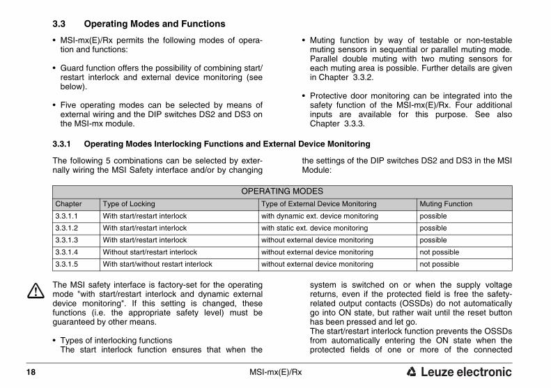
3.3 Operating Modes and Functions
• MSI-mx(E)/Rx permits the following modes of opera-tion and functions:
• Guard function offers the possibility of combining start/restart interlock and external device monitoring (see below).
• Five operating modes can be selected by means of external wiring and the DIP switches DS2 and DS3 on the MSI-mx module.
• Muting function by way of testable or non-testable muting sensors in sequential or parallel muting mode. Parallel double muting with two muting sensors for each muting area is possible. Further details are given in Chapter 3.3.2.
• Protective door monitoring can be integrated into the safety function of the MSI-mx(E)/Rx. Four additional inputs are available for this purpose. See also Chapter 3.3.3.
3.3.1 Operating Modes Interlocking Functions and External Device Monitoring
The following 5 combinations can be selected by exter-nally wiring the MSI Safety interface and/or by changing
the settings of the DIP switches DS2 and DS3 in the MSI Module:
The MSI safety interface is factory-set for the operating mode "with start/restart interlock and dynamic external device monitoring". If this setting is changed, these functions (i.e. the appropriate safety level) must be guaranteed by other means.
• Types of interlocking functions The start interlock function ensures that when the
system is switched on or when the supply voltage returns, even if the protected field is free the safety-related output contacts (OSSDs) do not automatically go into ON state, but rather wait until the reset button has been pressed and let go. The start/restart interlock function prevents the OSSDs from automatically entering the ON state when the protected fields of one or more of the connected
OPERATING MODES
Chapter Type of Locking Type of External Device Monitoring Muting Function
3.3.1.1 With start/restart interlock with dynamic ext. device monitoring possible
3.3.1.2 With start/restart interlock with static ext. device monitoring possible
3.3.1.3 With start/restart interlock without external device monitoring possible
3.3.1.4 Without start/restart interlock without external device monitoring not possible
3.3.1.5 With start/without restart interlock without external device monitoring not possible
MSI-mx(E)/Rx 19
SP
AN
ISC
HIT
AL
IEN
ISC
HF
RA
NZ
ÖS
ISC
HE
NG
LIS
CH
DE
UT
SC
H
AOPDs are released again after an interruption. Here as well, the reset button must be pressed and let go to initiate the system. Muting is not possible if there is no locking (and hence no reset button) since the start button is also used to perform the function muting reset.
• Types of External Device Monitoring The function dynamic external device monitoring moni-tors the relays connected downstream from the MSI safety interface. Each time before the OSSDs switch to the ON state, a check is made of whether the subse-quent circuit elements have closed and reopened. If they have not, the OSSDs of the MSI safety interface remain in the OFF state. If the function static external device monitoring is selected, a check is merely made of whether the subsequent circuit elements are in an open state. If they are, the start/restart interlock can be initiated.
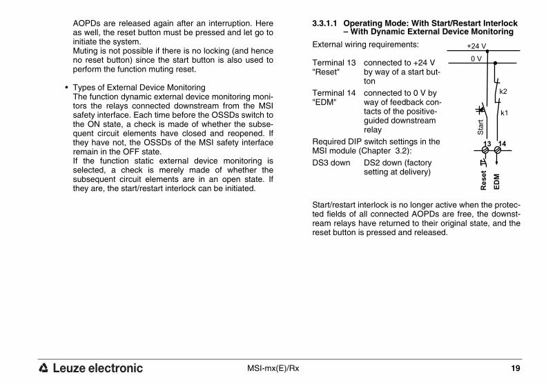
3.3.1.1 Operating Mode: With Start/Restart Interlock – With Dynamic External Device Monitoring
External wiring requirements:
Start/restart interlock is no longer active when the protec-ted fields of all connected AOPDs are free, the downst-ream relays have returned to their original state, and the reset button is pressed and released.
Terminal 13 "Reset"
connected to +24 V by way of a start but-ton
Terminal 14 "EDM"
connected to 0 V by way of feedback con-tacts of the positive-guided downstream relay
Required DIP switch settings in the MSI module (Chapter 3.2):
DS3 down DS2 down (factory setting at delivery)
Sta
rt
+24 V
0 V
k2
k1
13 14
Reset
ED
M

20 MSI-mx(E)/Rx
DE
UT
SC
HE
NG
LIS
CH
FR
AN
ZÖ
SIS
CH
ITA
LIE
NIS
CH
SP
AN
ISC
H
3.3.1.2 Operating Mode: With Start/Restart Interlock – With Static External Device Monitoring
External wiring requirements
In this operating mode, if the pro-tected fields are free, a check is merely made of whether the down-stream circuit elements have retur-ned to their original state. If so, a release is issued by pressing and letting go of the reset button.
The dynamic monitoring of the downstream relays, which may be required in order to maintain the safety category, must be performed by other means.
3.3.1.3 Operating Mode: With Start/Restart Interlock – Without External Device Monitoring
External wiring requirements:
The dynamic monitoring of the downstream relays, which may be required in order to maintain the safety category, must be performed by other means.
Terminal 13 "Reset"
connected to 24 V DC by way of a start but-ton
Terminal 14 "EDM"
connected to 0 V by way of feedback con-tacts of the positive-guided downstream relay
Required DIP switch settings in the MSI module (Chapter 3.2):
DS3 down DS2 up
Sta
rt
+24 V
0 V
k2
k1
13 14
Reset
ED
M
Terminal 13 "Reset"
connected to 24 V DC by way of a start button
Terminal 14 "EDM"
connected to 0 V
Required DIP switch settings in the MSI module (Chapter 3.2):
DS3 down DS2 up
Sta
rt
+24 V
0 V
13 14
Reset
ED
M

MSI-mx(E)/Rx 21
SP
AN
ISC
HIT
AL
IEN
ISC
HF
RA
NZ
ÖS
ISC
HE
NG
LIS
CH
DE
UT
SC
H
3.3.1.4 Operating Mode: Without Start/Restart Inter-lock – Without External Device Monitoring
Muting operation are not possi-ble in this operating mode!
External wiring requirements:
After the supply voltage is app-lied, the OSSDs immediately go into the ON state if all of the protected fields of the connected AOPDs are free.
In this case, the start/restart interlock function and the dynamic monitoring of the downstream relays, which may be required in order to maintain the safety category, must be performed by other means.
3.3.1.5 Operating Mode: With Start/Without Restart Interlock – Without External Device Monito-ring
Muting operation is not possible in this operating mode!
External wiring requirements:
After the supply voltage is app-lied, the OSSDs remain in the OFF state even if all of the protected fields of the connected AOPDs are free.
When the protected fields of all connected AOPDs are initially free, the OSSDs first enter the ON state when the protected field of the AOPD connected at S1 (for Type 4: S1 and S2) is interrupted and released. Only then do the rest of the connected AOPDs respond to the interruption and release of their own protected fields by switching the OSSDs directly to the OFF and ON states.
In this case, the start/restart interlock function and the dynamic monitoring of the downstream circuit elements, which may be required in order to maintain the safety category, must be performed by other means.
Terminal 13 "Reset"
connected to 0 V
Terminal 14 "EDM"
connected to 24 V DC
Required DIP switch settings in the MSI module (Chapter 3.2):DS3 down DS2 up
+24 V
0 V
14
Reset
ED
M
13
Terminal 13 "Reset"
connected to 0 V
Terminal 14 "EDM"
connected to 24 V DC
Required DIP switch settings in the MSI module (Chapter 3.2):DS3 up DS2 up
+24 V
0 V
14
Reset
ED
M
13

22 MSI-mx(E)/Rx
DE
UT
SC
HE
NG
LIS
CH
FR
AN
ZÖ
SIS
CH
ITA
LIE
NIS
CH
SP
AN
ISC
H
3.3.2 Muting Functions
Muting is the intended, regulated suppression of the protective function.Special safety precautions must be observed if muting is being used (see Chapter 2.6). Muting operation is initiated by the muting sensors con-nected to the MSI-mx. The MSI-mx can ascertain the muting mode based on which of the muting inputs (M1 to M4) are occupied. For instance, sequential muting will be performed when all inputs are occupied, and parallel muting takes place when M2 and M3 are occupied. Further more, both of the Muting indicators must be connected. See Chapter 3.3.2.5 for more details.
Parallel double muting requires the occupation of the muting inputs M2 and M3 as well as for the second muting path M1 and M4. Additionally, it is also necessary to change the DIP switch setting of MU1 in the muting I/O-mx module. See also Chapter 3.2.2.
Special note for muting Type 2 AOPDsWhen the DIP switch MU4 in the I/O-mx module is factory-set (down), the muting function applies for safety inputs S1 and S2. If a Type 2 AOPD is going to be muted, the muting range 1 must be reset to "S1 only” at MU4 (up). In addition, the Type 2 AOPD to be muted must be connected at S1. For the setting, see Chapter 3.2.2.
3.3.2.1 Sequential Muting, Muting sensors at M1 to M4
Sequential muting requires the connection of 4 muting sensors and their damping in a predetermined sequence. It is preferred when the material being transported (i.e. the transport vehicle) always has consistent dimensions and there is sufficient space available for the material
intake. Example: car bodies in the automobile industry. Examples are shown in Chapter 3.3.2.8 and 3.3.2.9.
3.3.2.2 Parallel Muting (2,5 s), Muting sensors M2 and M3
The muting process is initiated if the two inputs switch simultaneously (within 2.5 s of each other). Parallel muting is used when material of inconsistent size is being conveyed or when there is limited room in front of the muting station.
Parallel muting can be performed by two switches or two light barriers (through-beam operation or retro-reflective light barriers whose beam paths intersect behind the protected field but within the danger zone). Examples of these and other possibilities can be found from Chapter 3.3.2.8.
3.3.2.3 Parallel Double Muting (dual-range muting) using M2 and M3, M1 and M4
The MSI-mx(E)/Rx makes it possible to asynchronously suppress the safety function of the AOPDs located at both the system intake and the system output. This can be necessary, for instance, at a continuous production system. This supplementary muting function requires that the DIP switch MU1 in the I/O-mx module be up. As always, M2 and M3 influence the parallel muting of range 1 (S1 and S2). They must switch within 2.5 seconds of each other in order to initiate the muting process.
In this mode, the muting sensors connected at M1 and M4 influence the muting of range 2 (S3 and S4). The same condition as above applies here: the two sensors
MSI-mx(E)/Rx 23
SP
AN
ISC
HIT
AL
IEN
ISC
HF
RA
NZ
ÖS
ISC
HE
NG
LIS
CH
DE
UT
SC
H
must switch within 2.5 seconds of each other in order to initiate the muting process for range 2. See the example in Chapter 3.3.2.12.
Special note for the parallel double muting of Type 2 AOPDsWhen the DIP switch MU1 in the I/O-mx module is up, the muting function takes effect both for muting range 1 (S1 and S2) and for muting range 2 (S3 and S4). This factory set mode is required for AOPDs Type 4. If Type 2 AODPs are going to be muted, muting range 1 must be set to "S1 only” at MU4 and muting range 2 must be set to "S3 only” at MU5 (for the settings see Chapter 3.2.2). The Type 2 AOPDs to be muted must be connected at S1 and S3. For Setting, see Chapter 3.2.2.
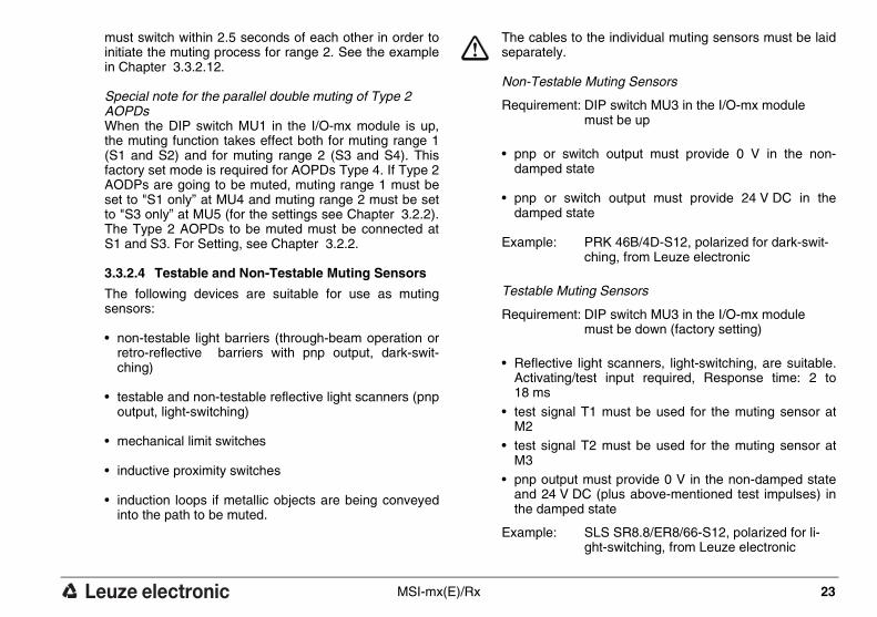
3.3.2.4 Testable and Non-Testable Muting Sensors
The following devices are suitable for use as muting sensors:
• non-testable light barriers (through-beam operation or retro-reflective barriers with pnp output, dark-swit-ching)
• testable and non-testable reflective light scanners (pnp output, light-switching)
• mechanical limit switches
• inductive proximity switches
• induction loops if metallic objects are being conveyed into the path to be muted.
The cables to the individual muting sensors must be laid separately.
Non-Testable Muting Sensors
• pnp or switch output must provide 0 V in the non-damped state
• pnp or switch output must provide 24 V DC in the damped state
Testable Muting Sensors
• Reflective light scanners, light-switching, are suitable. Activating/test input required, Response time: 2 to 18 ms
• test signal T1 must be used for the muting sensor at M2
• test signal T2 must be used for the muting sensor at M3
• pnp output must provide 0 V in the non-damped state and 24 V DC (plus above-mentioned test impulses) in the damped state
Requirement: DIP switch MU3 in the I/O-mx module must be up
Example: PRK 46B/4D-S12, polarized for dark-swit-ching, from Leuze electronic
Requirement: DIP switch MU3 in the I/O-mx module must be down (factory setting)
Example: SLS SR8.8/ER8/66-S12, polarized for li-ght-switching, from Leuze electronic

24 MSI-mx(E)/Rx
DE
UT
SC
HE
NG
LIS
CH
FR
AN
ZÖ
SIS
CH
ITA
LIE
NIS
CH
SP
AN
ISC
H
3.3.2.5 Muting Display Function
Single muting for S1/S2, or in the case of type 2 for S1 onlyIn case of muting, terminal 28 will deliver 24 V DC to the Muting indicator 1 connected to it to indicate the muting.
Terminal 29 serves as backup for the case that Muting indicator 1, which is connected to terminal 28, should fail (broken filament or interrupted supply). To ensure trouble-free operation, also in the case of malfunction of Muting indicators 1 connected to terminal 28, a Muting indicator 2 must be connected to terminal 29 to serve as back-up unit to take over the indicating function in case of failure.
With the automatic switching over from Muting indicator 1 to Muting indicator 2, the assigned LED “lamp warn " on the I/O mx module will flash up (1 pulse). If Muting indicator 2 should fail (it is monitored constantly, even if it is not switched on), the LED "lamp warn " will also flash up (2 pulse).
In addition to the indication, these pulses (1 pulse or 2 pulses) are also directed to output terminal 30. This output will deliver an active - high signal during trouble-free operation. However, if the second indicator also fails, the MSI-mx(E)/Rx will enter a state of malfunction and the OSSDs will switch to the OFF state.
Special Note for Double MutingIf via the DIP switch MU1 double muting is selected, the output terminal 28 takes over the muting indication of the muting range 1, the output terminal 29 indicates muting for the muting range 2. In this muting mode, the
MSI-mx(E)/Rx immediately enters the state of mal-function if one of the two display indicators fails.
3.3.2.6 Muting Restart while transported goods are located in the muting area
If there are transported goods in the muting area when the power is switched on (after mains failure, emergency stops or muting sequence failure) a muting restart is required.
In case of the conveyor system covers at least one muting sensor but not the sensing field of the AOPD to be muted, pressing and releasing the reset button activates the transporting system. Muting is not activated. As soon as the transported goods interrupt the sensing field of the AOPD to be muted, the OSSDs are switching into the OFF-state and the Muting indicators start to blink. Muting restart is now possible.
In case of the conveyor covers at least one muting sensor and, at the same time, the sensing field of the AOPD to be muted when power is switched on, the OSSDs stay in the OFF-position while the Muting indica-tors are blinking. Muting restart is immediately possible.
Muting restart requires pressing the reset button two times within 4 s. On the second activation of the start button the OSSDs immediately are switching to the ON-state. On the second release of the start button the MSI-mx(E)/Rx safety interface checks the muting sen-sors for a valid state.
If the check ascertains a normal condition of the muting sensors, the OSSDs will stay in the ON-state. The system takes on normal conditions.

MSI-mx(E)/Rx 25
SP
AN
ISC
HIT
AL
IEN
ISC
HF
RA
NZ
ÖS
ISC
HE
NG
LIS
CH
DE
UT
SC
H
If an invalid combination is detected, the release remains in effect only as long as the start button continues to be pressed. As soon as the button is released, the system comes to a standstill. Thus it is possible to enable and operate the system as long as a responsible person constantly observes the process and can interrupt the dangerous movement at any time by letting go of the start button. In this case, the muting sensors have to be checked for misalignment, contamination or damage.
This option assumes that the start button, as stated in the safety precautions (Chapter 2.6) is mounted in a location from which the entire danger zone can be viewed.
3.3.2.7 10-Minute Muting Time-Limit
Regardless of the selected muting mode, the MSI safety interface reports a muting malfunction when the duration of a muting state exceeds 10 minutes. Using parallel double muting the OSSDs switch to the OFF-state and the MSI shows muting faults, when one of the two muting ranges exceeds the time limit.
The muting time limit is mandatory. The muting time limit may only be switched off with DIP switch MU2 in the I/O-mx module in well-grounded cases, e.g. for a nor-mally uninterrupted flow of goods in the muting path and if no persons are thereby endangered.
26 MSI-mx(E)/Rx
DE
UT
SC
HE
NG
LIS
CH
FR
AN
ZÖ
SIS
CH
ITA
LIE
NIS
CH
SP
AN
ISC
H
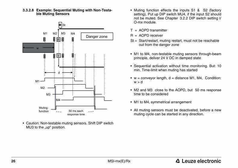
3.3.2.8 Example: Sequential Muting with Non-Testa-ble Muting Sensors
• Caution: Non-testable muting sensors. Shift DIP switch MU3 to the „up“ position.
• Muting function effects the inputs S1 & S2 (factory setting). Put up DIP switch MU4, if the input S2 should not be muted. See Chapter 3.2.2 DIP switch setting I/O-mx module.
• M1 to M4, non-testable muting sensors through-beam principle, deliver 24 V DC in damped state
• Sequential activation without time monitoring. But: 10 min. Time-limit when muting has started
• w = conveyor length, d = distance M1, M4, Condition: w > d
• M2 and M3 close to the AOPD, but 50 ms response time to be considered
• M1 to M4, symmetrical arrangement
• All muting sensors must be deactivated, before a new muting cycle can be started in any direction.
M1 M2 M3 M4
w
d
R
T
M1
M2
M3
M4
St
S
E E E E
S
50 ms eachresponse time
Danger zone
Muting-function
S S
T = AOPD transmitterR = AOPD receiverSt = Start/restart, muting restart, must not be reachable
out from the danger zone

MSI-mx(E)/Rx 27
SP
AN
ISC
HIT
AL
IEN
ISC
HF
RA
NZ
ÖS
ISC
HE
NG
LIS
CH
DE
UT
SC
H
3.3.2.9 Example: Sequential Muting with Testable Muting Sensors
• Caution: Testable muting sensors. DIP switch MU3 „down“ position (factory setting)
• Muting function effects the inputs S1 & S2 (factory setting). Put up DIP switch MU4, if the input S2 should not be muted. See Chapter 3.2.2 DIP switch setting I/O-mx module.
• T1, T2 test signal outputs
• M1 to M4, testable muting sensors scanning principle, provide 24 V DC in damped state
• Sequential activation without time monitoring. But: 10 min. Time-limit when muting has started
• w = conveyor length, d = distance M1, M4, Condition: w > d
• Positioning of M2 and M3 as close as possible to the AOPD, but consider 50 ms response time
• M1 to M4, symmetrical arrangement
• All muting sensors must be deactivated, before a new muting cycle can start in any direction.
M1 M2 M3 M4
w
d
R
T
St
T1T2
M1
M2
M3
M4
50 ms eachresponse time
Danger zone
Muting-function
T = AOPD transmitterR = AOPD receiverSt = Start/restart, muting restart, must not be reachable
out from the danger zone
28 MSI-mx(E)/Rx
DE
UT
SC
HE
NG
LIS
CH
FR
AN
ZÖ
SIS
CH
ITA
LIE
NIS
CH
SP
AN
ISC
H
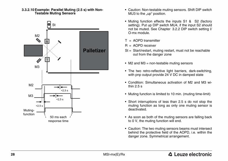
3.3.2.10 Example: Parallel Muting (2.5 s) with Non-Testable Muting Sensors
• Caution: Non-testable muting sensors. Shift DIP switch MU3 to the „up“ position.
• Muting function effects the inputs S1 & S2 (factory setting). Put up DIP switch MU4, if the input S2 should not be muted. See Chapter 3.2.2 DIP switch setting I/O-mx module.
• M2 and M3 = non-testable muting sensors
• The two retro-reflective light barriers, dark-switching, with pnp output provide 24 V DC in damped state
• Condition: Simultaneous activation of M2 and M3 wi-thin 2.5 s
• Muting function is limited to 10 min. (muting time-limit)
• Short interruptions of less than 2.5 s do not stop the muting function as long as only one muting sensor is deactivated.
• As soon as both of the muting sensors are falling back to 0 V, the muting function will end.
• Caution: The two muting sensors beams must intersect behind the protective field of the AOPD, i.e. within the danger zone. Symmetrical arrangement.
M2
M3
R
T
St
M2
M3
<2,5 s
<2,5 s
<2,5 s
50 ms eachresponse time
Palletizer
Muting-function
T = AOPD transmitterR = AOPD receiverSt = Start/restart, muting restart, must not be reachable
out from the danger zone

MSI-mx(E)/Rx 29
SP
AN
ISC
HIT
AL
IEN
ISC
HF
RA
NZ
ÖS
ISC
HE
NG
LIS
CH
DE
UT
SC
H
3.3.2.11 Example: Parallel Muting (2.5 s) with Testa-ble Muting Sensors
• Caution: Testable muting sensors. DIP switch MU3 „down“ position (factory setting)
• Muting function effects the inputs S1 & S2 (factory setting). Put up DIP switch MU4, if the input S2 should not be muted. See Chapter 3.2.2 DIP switch setting I/O-mx module.
• T1, T2 test signal outputs
• M2 and M3, M2’ and M3’ = testable muting sensors
• The four reflective light scanners, light-switching, with pnp output provide 24 V DC in damped state.
• Condition: Simultaneous activation of M2 and M3 or M2’ and M3’ within 2.5 s
• Muting function is limited to 10 min. (muting time-limit)
• Short interruptions of less than 2.5 s do not stop the muting function as long as only one muting sensor is deactivated.
• As soon as both of the muting sensors are falling back to 0 V, the muting function will end.
• M2, M2’, M3 and M3’ should be mounted as near as possible to the protective field, but the response time of 50 ms must be considered. Symmetrical arrangement.
M2
M3
M2' M2
M3 M3'
R
T
St
T1
T2
M2
M3
<2,5 s
<2,5 s
<2,5 s
50 ms eachresponse time
Palletizer
Muting-function
T = AOPD transmitterR = AOPD receiverSt = Start/restart, muting restart, must not be reachable
out from the danger zone
30 MSI-mx(E)/Rx
DE
UT
SC
HE
NG
LIS
CH
FR
AN
ZÖ
SIS
CH
ITA
LIE
NIS
CH
SP
AN
ISC
H
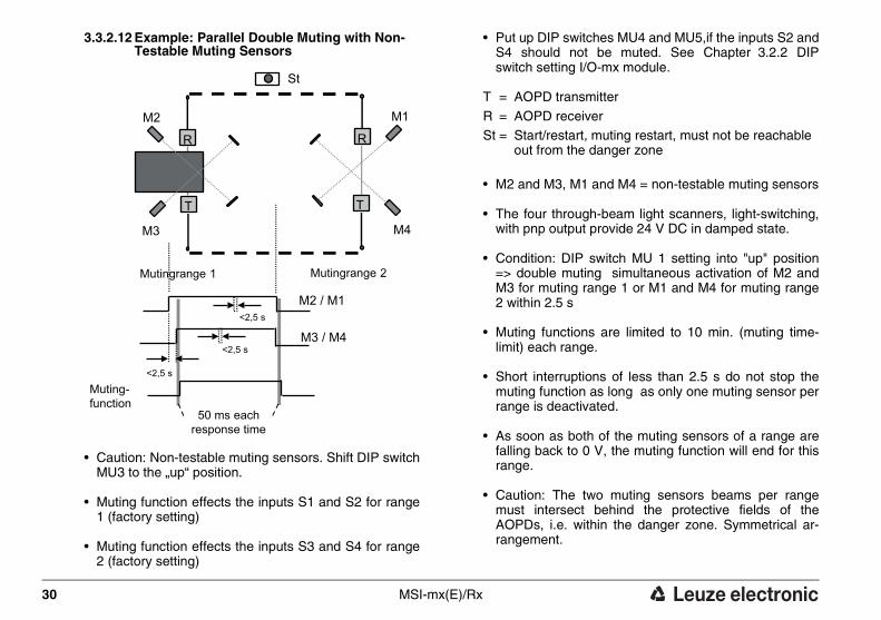
3.3.2.12 Example: Parallel Double Muting with Non-Testable Muting Sensors
• Caution: Non-testable muting sensors. Shift DIP switch MU3 to the „up“ position.
• Muting function effects the inputs S1 and S2 for range 1 (factory setting)
• Muting function effects the inputs S3 and S4 for range 2 (factory setting)
• Put up DIP switches MU4 and MU5,if the inputs S2 and S4 should not be muted. See Chapter 3.2.2 DIP switch setting I/O-mx module.
• M2 and M3, M1 and M4 = non-testable muting sensors
• The four through-beam light scanners, light-switching, with pnp output provide 24 V DC in damped state.
• Condition: DIP switch MU 1 setting into "up" position => double muting simultaneous activation of M2 and M3 for muting range 1 or M1 and M4 for muting range 2 within 2.5 s
• Muting functions are limited to 10 min. (muting time-limit) each range.
• Short interruptions of less than 2.5 s do not stop the muting function as long as only one muting sensor per range is deactivated.
• As soon as both of the muting sensors of a range are falling back to 0 V, the muting function will end for this range.
• Caution: The two muting sensors beams per range must intersect behind the protective fields of the AOPDs, i.e. within the danger zone. Symmetrical ar-rangement.
M2 / M1
M3 / M4
<2,5 s
<2,5 s
<2,5 s
St
M2
M3
R
T
M1
M4
R
T
Muting-function
50 ms eachresponse time
Mutingrange 1 Mutingrange 2
T = AOPD transmitter
R = AOPD receiverSt = Start/restart, muting restart, must not be reachable
out from the danger zone

MSI-mx(E)/Rx 31
SP
AN
ISC
HIT
AL
IEN
ISC
HF
RA
NZ
ÖS
ISC
HE
NG
LIS
CH
DE
UT
SC
H
3.3.3 Protective Door Monitoring
When assessing risk, it is also important to consider whether people can be enclosed and trapped in the danger zone if a transport vehicle is located in the muting path. The additional danger of crushing can exist if the requirement is set and enforced to eliminate all access except for the transport vehicle.
In such cases, swinging doors with protective door moni-tors have proven useful. In contrast to stationary fixed elements, these doors move toward the transport vehicle, yield to slight pressure and serve as an escape route. However, their use must be incorporated into the overall safety concept. Two protective doors with two switches each can be integrated into the safety circuit with the
MSI-mx(E)/Rx . After the start button has been pressed, the precondition for enabling operation is that the swit-ches at 1.1 and 1.2 (or at 2.1 and 2.2) must have closed within 1 s of each other.
The connectable protective door switches can take over other tasks, such as monitoring rear doors or other accesses to the machine and switching off the machine as soon as these are opened.A emergency stop push button can also be connected instedd of a safety inter-lock. Safety switch inputs must be connected. If no switches on the MSI-mx(E)/Rx are used, bridges must simulate these connections.
3.3.4 Relay Operation Monitoring Function Pre-failure Message in /Rx Versions
For purposes of preventive maintenance, the /Rx output subassemblies are equipped with a function that counts the number of relay operations and issues a pre-failure message. Four different values can be selected at the DIP switches on the subassembly. Before the DIP swit-ches can be set, the Rx subassembly must be completely disconnected from all power sources. It can then be
released from its two holding brackets with a screwdriver and pulled slightly out of the housing.
The table below shows the recommended DIP switch settings with respect to the switching current. Switching voltages of up to 60 V DC and 250 V AC are admissible.
For setting, see Chapter 3.2.3
OSSD Switching current (Switching Voltage 60 V DC, 250 V AC max.)
≤ 0.75 A > 0.75 A ≤1.5 A
>1.5 A ≤ 3 A
> 3 A ≤ 5 A
Recommended number of operations 1,000,000 500,000 200,000 100,000

32 MSI-mx(E)/Rx
DE
UT
SC
HE
NG
LIS
CH
FR
AN
ZÖ
SIS
CH
ITA
LIE
NIS
CH
SP
AN
ISC
H
3.4 Displays
A number of LEDs of various colors indicate the opera-ting status of the MSI modular safety interface. It is also possible to show the LED displays on the PC monitor
using the integrated RS 232 interface and diagnosis connector.
Output /Rx
Position Display/Function Symbol Status LED Color
1 Preset no. of relayoperations (/Rx only)
relaywarn.
reachednot reached
onoff
red
2 Safety-related switch output relay onoff
onon
greenred
3 Start/restart interlock lock lockednot locked
onoff
yellow
4 Fault in output module relay faultno fault
onoff
red
lampwarn.
MutingFault
Switch1
Switch2
25 26 2728 29 30
31 32 3334 35 36
Fault
Warn.
State
Locked
7 8 910 11 12
OutputRx -
Leuze
1 2 34 5 6
1
2
3
4
Rx-OutputModule
MSI-mxModule
MSI-mx
Diagn.
S1 & S2
S3 & S4
FaultMSI
electronic
13 14 1516 17 18
19 20 2122 23 24
5
6
7
8 12
11
10
9
I/O-mxModule

MSI-mx(E)/Rx 33
SP
AN
ISC
HIT
AL
IEN
ISC
HF
RA
NZ
ÖS
ISC
HE
NG
LIS
CH
DE
UT
SC
H
* The switches must be closed within 1 second of each other.
MSI-mx Module
Position Display/Function Symbol Status LED Color
5 Diagnosis, RS 232See status outputs
jackdiagn.
none none none
6 Protected field AOPDsS3 & S4
protected field freenot free
onoff
green
7 Protected field AOPDsS1 & S2
protected field freenot free
onoff
green
8 MSI fault MSI fault faultno fault
onoff
red
I/O-mx Module
Position Anzeige/Funktion Symbol Status LED Color
9 Safety switches1.1-1.2
contactsswitch
both closed*not closed
onoff
green
10 Safety switches2.1-2.2
contactsswitch
both closed*not closed
onoff
green
11 Muting indicator broken filamentshort circuitinteruption
defect indicator 1defect indicator 2no defect
blinks 1 xblinks 2 xoff
redred
12 Muting failure sequenceerror
failureno failure
onoff
red

34 MSI-mx(E)/Rx
DE
UT
SC
HE
NG
LIS
CH
FR
AN
ZÖ
SIS
CH
ITA
LIE
NIS
CH
SP
AN
ISC
H
3.5 Status Outputs
Status outputs are not allowed to be used as safety-related signals in release circuits
(see also Chapter 2. Operating Conditions and Proper Use).
Output /Rx
Terminal Message Function Symbol Status Status Output
5 preset no. of relayoperations (/Rx only)
relay not reachedreached
active highactive low
6 Start/restart interlock lock lockednot locked
active highactive low
7 Safety-related switch status relay ONOFF
active highactive low
T1 T2 S1 S2
AOPDsTest
+24V
Diagn.
0 V
9
4 15 24 22 23 13 1420 21 31 32
MutingIndicators
1 2
Warn.
S3 S4
16 17
1.1 1.2 2.1 2.2
Safety Switches
M1 M2 M3 M4
Muting Sensors
25 26 34 35
State Outputs
S1-S
4
1.1-
2.2
Mut
ing
Mut
ing
Failu
re
18 19 27 36 33 30 28 29
Leuze electronicMSI-mx(E)/Rx
RS
232
Rx-Output
Res
et
EDM
StateWarn.
7 65
MSI-fault
11 2
12 110 3
OSS
D1
OSS
D3
OSS
D2
SSD
N.O
.N
.C.
N.O
.

MSI-mx(E)/Rx 35
SP
AN
ISC
HIT
AL
IEN
ISC
HF
RA
NZ
ÖS
ISC
HE
NG
LIS
CH
DE
UT
SC
H
* Terminal 29 as backup
Terminal 28 muting range 1 Terminal 29 muting range 2
MSI-mx Module
Terminal Message Function Symbol Status Status Output
Front jack Diagnosis, RS 2322.5 mm round connector
– – connected to PC with diagnosis program
18 MSI Fault MSI-fault not faultfault
active highactive low
19 Protected field(s) S1 - S4 freenot (all) free
active highactive low
I/O-mx Module
Terminal Message Function Symbol Status Status Output
27 Safety switches 1.1 - 2.2 1.1 - 2.2 closednot closed
active highactive low
28 Muting indicator24 V DC, 5 W max.
lamp muting onmuting off
active highactive low
29 Muting indicator24 V DC, 5 W max.
lamp muting onmuting off
active highactive low
30 WarningMuting indicator defective
broken filamentshort circuitinteruption
indicator OKdefect indicator 1defect indicator 2
active highimpulse 1ximpulse 2x
33 Muting failure Muting Failure no failuremuting failure
active highactive low
36 Muting status Muting muting onmuting off
active highactive low

36 MSI-mx(E)/Rx
DE
UT
SC
HE
NG
LIS
CH
FR
AN
ZÖ
SIS
CH
ITA
LIE
NIS
CH
SP
AN
ISC
H
3.6 Diagnosis System
Requirements for running the diagnosis system: a stan-dard PC or laptop operating under Windows (Version 3.1 or higher) and the MSI software, Version 01, as well as a serial connection cable and a 2.5 mm jack plug.
• Simultaneous display of all input and output statuses as well as all LED displays on the MSI
With its diagnosis interface, the intelligent modular safety interface MSI offers a convenient way to visualize all of the input and output statuses simultaneously on the monitor. The connection circuit diagram as well as dis-play fields in different colors can be shown on the screen via the connection terminals. A graphic representation of the MSI front design with the display elements as descri-bed in Chapter 3.4 also appears on the screen.
Example:
This enables the sequences at individual screw-type terminals to be trakked without the use of additional measuring instru-ments. The diagnosis function is equipped with on-line help and can be operated in either English or German.
Leuze electronic
Leuze electronic
MSI-mx(E)/Rx 37
SP
AN
ISC
HIT
AL
IEN
ISC
HF
RA
NZ
ÖS
ISC
HE
NG
LIS
CH
DE
UT
SC
H
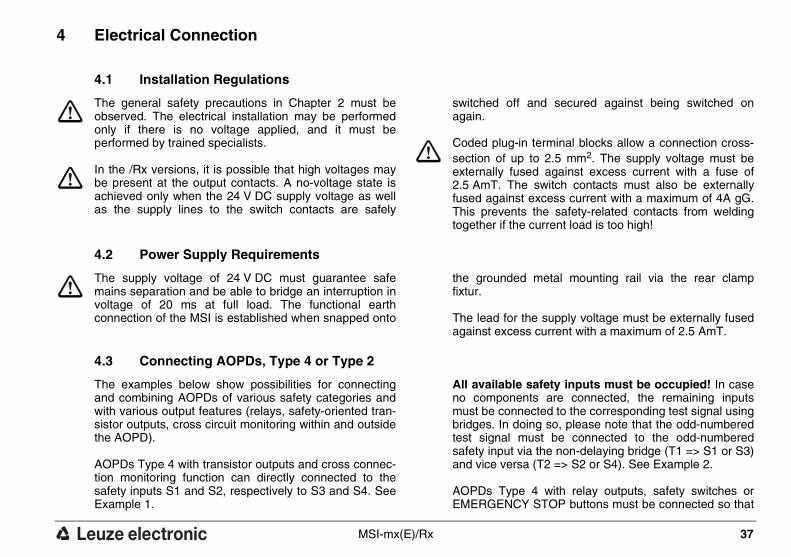
4 Electrical Connection
4.1 Installation Regulations
The general safety precautions in Chapter 2 must be observed. The electrical installation may be performed only if there is no voltage applied, and it must be performed by trained specialists.
In the /Rx versions, it is possible that high voltages may be present at the output contacts. A no-voltage state is achieved only when the 24 V DC supply voltage as well as the supply lines to the switch contacts are safely
switched off and secured against being switched on again.
Coded plug-in terminal blocks allow a connection cross-section of up to 2.5 mm2. The supply voltage must be externally fused against excess current with a fuse of 2.5 AmT. The switch contacts must also be externally fused against excess current with a maximum of 4A gG. This prevents the safety-related contacts from welding together if the current load is too high!
4.2 Power Supply Requirements
The supply voltage of 24 V DC must guarantee safe mains separation and be able to bridge an interruption in voltage of 20 ms at full load. The functional earth connection of the MSI is established when snapped onto
the grounded metal mounting rail via the rear clamp fixtur.
The lead for the supply voltage must be externally fused against excess current with a maximum of 2.5 AmT.
4.3 Connecting AOPDs, Type 4 or Type 2
The examples below show possibilities for connecting and combining AOPDs of various safety categories and with various output features (relays, safety-oriented tran-sistor outputs, cross circuit monitoring within and outside the AOPD).
AOPDs Type 4 with transistor outputs and cross connec-tion monitoring function can directly connected to the safety inputs S1 and S2, respectively to S3 and S4. See Example 1.
All available safety inputs must be occupied! In case no components are connected, the remaining inputs must be connected to the corresponding test signal using bridges. In doing so, please note that the odd-numbered test signal must be connected to the odd-numbered safety input via the non-delaying bridge (T1 => S1 or S3) and vice versa (T2 => S2 or S4). See Example 2.
AOPDs Type 4 with relay outputs, safety switches or EMERGENCY STOP buttons must be connected so that

38 MSI-mx(E)/Rx
DE
UT
SC
HE
NG
LIS
CH
FR
AN
ZÖ
SIS
CH
ITA
LIE
NIS
CH
SP
AN
ISC
H
the odd-numbered test signal T1 are directed via the non-delaying contacts to an odd-numbered safety input (T1=>S1 or S3) and vice versa (T2=>S2 or S4). See Example 3 and 4.
AOPDs Type 2 are periodically tested using the time-displaced test signals T1 or T2. The odd-numbered test signal must be directed to an even-numbered safety input by the way of the time-delaying AOPD (T1=>S2 or S4) and vice versa (T2=>S1 or S3). The AOPD response time to a test request must be in a range of 2 to 18 ms. See Example 5 and 6.
Using both, the safety inputs S1 & S2 and S3 & S4 separate insulated connector cables must be used to avoid undetected cross connections. Cross connections will be detected between S1 and S2 as well as between S3 and S 4, but not between S1 and S3 or S2 and S 4!
If type 2 AOPDs are connected:
• when cables are laid with protection according to EN ISO 13849-1, a Performance Level up to d and category 2 can be achieved
• when cables are laid without protection, a failure detec-tion time of up to 10 s is possible.

MSI-mx(E)/Rx 39
SP
AN
ISC
HIT
AL
IEN
ISC
HF
RA
NZ
ÖS
ISC
HE
NG
LIS
CH
DE
UT
SC
H
Example 1 2 AOPD Typ 4 with 2 safety-related transistor outputs each and internal cross connection monitoring function.
Example 2 1 AOPD Typ 4 with 2 safety-related transistor outputs and internal cross connection monitoring.
Example 3 2 AOPD Typ 4 with 2 normally open contacts each. Separated connection cables to the individual AOPDs are required.
AOPD
TYP 4
2 x pnp
T2 S1 S2 S3
AOPDsTest
24 22 23 16 17
S4
AOPD
TYP 4
2 x pnp
T1
15
T2 S1 S2 S3
AOPDsTest
24 22 23 16 17
S4
AOPD
TYP 4
2 x pnp
T1
15
AOPD TYP 4
2 x relaysAOPD TYP 4
2 x relays
T2 S1 S2 S3
AOPDsTest
24 22 23 16 17
S4T1
15

40 MSI-mx(E)/Rx
DE
UT
SC
HE
NG
LIS
CH
FR
AN
ZÖ
SIS
CH
ITA
LIE
NIS
CH
SP
AN
ISC
H
Example 4 1 AOPD Type 4 with 2 normally open contacts and 1 safety switch. Separa-ted connection cables to the individual safety components are required.
Example 5 3 AOPDs Type 2 with 1 safety-related transistor output each. Separated con-nection cables to the individual AOPDs are required.
Example 6 4 AOPDs Type 2 with 1 safety-related transistor output each. Separated con-nection cables to the individual AOPDs are required
AOPD TYP 4
2 x relays
T2 S1 S2 S3
AOPDsTest
24 22 23 16 17
S4T1
15
Door
safety switch
T2 S1 S2 S3
AOPDsTest
24 22 23 16 17
S4T1
15
AOPD
TYP 2
1 x pnp
test in
put
test in
put
test in
put
AOPD
TYP 2
1 x pnp
AOPD
TYP 2
1 x pnp
T2 S1 S2 S3
AOPDsTest
24 22 23 16 17
S4T1
15
AOPD
TYP 2
1 x pnp
AOPD
TYP 2
1 x pnp
AOPD
TYP 2
1 x pnp
AOPD
TYP 2
1 x pnp
test in
put
test in
put
test in
put
test in
put
MSI-mx(E)/Rx 41
SP
AN
ISC
HIT
AL
IEN
ISC
HF
RA
NZ
ÖS
ISC
HE
NG
LIS
CH
DE
UT
SC
H
4.4 Connecting Machine Controls
The safety-related parts of the controls comprise more than the MSI-mx(E)/Rx described above. They also include successive control elements and even power transmission elements which must be safely and promptly shut down. Particular attention must be paid to maintaining the safety category requirements. Important information in this regard can be found in the harmonized European standard EN ISO 13849-1.
Essential prerequisites for safe operation are the abilities to electrically influence the interruption of the dangerous movement and to bring the machine to a standstill as
quickly as possible. These factors, as well as the re-sponse times of AOPDs and the MSI, must be taken into consideration when calculating the safety distance.
The response times depend on the type of AOPD selec-ted (see Chapter 6, Technical Data). Other parameters, such as hand/arm/body approach speed or additional safety distance, depend on the particular application and the resolution of the AOPD being used. The European standard EN 999 contains equations and examples for a variety of configurations.

42 MSI-mx(E)/Rx
DE
UT
SC
HE
NG
LIS
CH
FR
AN
ZÖ
SIS
CH
ITA
LIE
NIS
CH
SP
AN
ISC
H
5 Connection Circuit Diagram, Examples
The connection example below shows a wiring sugge-stion each for the MSI-mx(E)/Rx.
Connection example MSI-mx(E)/Rx with two AOPD Type 4 and two safety switches.
M1 M2
+24 V
0 V
L+Ph
L-N
K1*
K3*
24 V
, 5 W
max
24 V
, 5 W
max
L-N
L-N
K2*
L+Ph
k2
k1
k3
M3 M4
T1 T2 S1 S2AOPDsTest
+24V
Diagn.
0 V
9
4 15 24 22 23 13 1420 21 31 32
MutingIndicators
1 2
Warn.
S3 S4
16 17
1.1 1.2 2.1 2.2Safety Switches
M1 M2 M3 M4Muting Sensors
25 26 34 35
State Outputs
S1-S
4
1.1-
2.2
Mut
ing
Mut
ing
Failu
re
18 19 27 36 33 30 28 29
Leuze electronicMSI-mx(E)/Rx
RS
232
Rx-Output
Res
et
EDM
StateWarn.
7 65
MSI-fault
11 2
12 110 3O
SSD
1
OSS
D3
OSS
D2
SSD
N.O
.
N.C
.
N.O
.
k1
k1
k2k2 k3
k3
b
a
e
c d f g
j k
ih ** **

MSI-mx(E)/Rx 43
SP
AN
ISC
HIT
AL
IEN
ISC
HF
RA
NZ
ÖS
ISC
HE
NG
LIS
CH
DE
UT
SC
H
a = AOPD Type 4 with guarding functionb = AOPD Type 4 with guarding and muting function
c = Door safety switch 1 (or emergency stop push button)d = Door safety switch 2e = M1, M2, M3, M4, Non-testable muting sensors (i.e. through-beam, dark
switching), sequential mode f = Command device for releasing the start/restart interlockg = Feedback loop for external device monitoring
h = Possible collective output for warning/error indicationsPin 18 = Indicating output "MSI Fault”Pin 19 = Indicating output "sensor status"
Pin 27 = Indicating output "safety switches status"Pin 36 = Indicating output "muting status"Pin 33 = Indicating output "muting failure"
Pin 30 = Warning output "Muting indicator defective"Pin 28/29 = Output Muting indicators 1 and 2Pin 5 = Warning output "relay pre-failure message"
Pin 7 = Indicating output ”status safety outputs”Pin 6 = Indicating output ”status start/restart interlock”i = Output Signal Switching Devices (OSSDs)
Pin 3 = Secondary Switching Device (SSD) opens in case of MSI-failuresj = Switching off path with two-channel controlk = Switching off path with one-channel control
* = Suitable spark suppression required** = In general, at least two of the contacts must be used in the subsequent machine
control path. Use relays or contactors with positive-driven contacts only.
All available safety inputs must be occupied! See Chapter 4.3.

44 MSI-mx(E)/Rx
DE
UT
SC
HE
NG
LIS
CH
FR
AN
ZÖ
SIS
CH
ITA
LIE
NIS
CH
SP
AN
ISC
H
6 Technical Data and Ordering Information
6.1 MSI-mx(E)/Rx
Version, TypeModular Safety Interface
MSI-mx(E)/Rx
Type in accordance with IEC/EN 61496 Type 4
SIL in accordance with IEC 61508 SIL 3
Performance Level (PL) in accordance with ISO 13849-1: 2008
PL e
Category in accordance with ISO 13849-1 Cat. 4
Mean probability of a dangerous failure per hour (PF-Hd ) as a function of the mean number of annual swit-ching cycles of the relay nop*
100% Load nop = 4.800: 1,6 x 10-08 1/h 60% Load nop = 4.800: 1,3 x 10-08 1/h100% Load nop = 28.800: 3,8 x 10-08 1/h60% Load nop = 28.800: 1,6 x 10-08 1/h100% Load nop = 86.400: 9,5 x 10-08 1/h60% Load nop = 86.400: 2,4 x 10-08 1/h
Number of cycles until 10 % of the components have a failure to danger (B10d)
400,000: 100% of the max. switched current of loading cases AC1..DC132,500,000: 60% of the max. switched current of loading cases AC1..DC1320,000,000: 60% of the max. switched current of loading cases AC1..DC13
Service life (TM) 20 years
Connectable safety sensors S1 - S4
up to 2 AOPDs, Type 4, Type 3 or up to 4 AOPDs, Type 2 (all in accordance with EN IEC 61496)
Connectable safety switches andcommand units at 1.1-2.2
Safety switches according to EN 1088Area Emergency-Stop button according to EN ISO 13850
Test outputs T1 and T2, Test intervalTest impulses, time-displacedResponse time AOPD Type 2 to a test request
200 ms24 ms each
2 to 18 ms
MSI-mx(E)/Rx 45
SP
AN
ISC
HIT
AL
IEN
ISC
HF
RA
NZ
ÖS
ISC
HE
NG
LIS
CH
DE
UT
SC
H
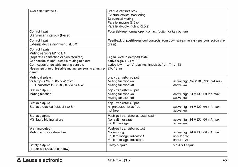
Available functions Start/restart interlockExternal device monitoringSequential mutingParallel muting (2.5 s)Parallel double muting (2.5 s)
Control inputStart/restart interlock (Reset)
Potential-free normal open contact (button or key button)
Control inputExternal device monitoring (EDM)
Feedback of positive-guided contacts from downstream relays (see connection dia-gram)
Control inputs Muting sensors M1 to M4(separate connection cables required)Connection of non-testable muting sensorsConnection of testable muting sensorsResponse time of testable muting sensors to a test re-quest
Signal level in damped state:active high, + 24 Vactive low, + 24 V, plus test impulses from T1 or T2 2 to 18 ms
Muting displaysfor lamps s 24 V DC/ 5 W max..LED indicators 24 V DC, 0,5 W to 5 W
pnp - transistor outputMuting function on Muting function off
active high, 24 V DC, 200 mA max.active low
Status outputMuting function
pnp - transistor outputMuting function on Muting function off
active high,24 V DC, 60 mA max.active low
Status outputs Status protected fields S1 to S4
pnp - transistor outputAll protected fields free not free
active high,24 V DC, 60 mA max.active low
Status outputsMSI fault, Muting failure
Push-pull transistor outputs, eachNo fault message Fault message
active high,24 V DC, 60 mA max.active low
Warning outputMuting indicator defective
Push-pull transistor outputNo warning Fault message indicator 1Fault message indicator 2
active high,24 V DC, 60 mA max.impulse 1ximpulse 2x
Safety outputs(Technical Data, see below)
Relay outputs via /Rx-Output

46 MSI-mx(E)/Rx
DE
UT
SC
HE
NG
LIS
CH
FR
AN
ZÖ
SIS
CH
ITA
LIE
NIS
CH
SP
AN
ISC
H
Supply voltage 24 V DC, ± 20%, external power supply (PELV, EN 60204-1) with safe mains sepa-ration and equalization for 20 ms voltage interruption required
Current consumption approx. 200 mA without external load
External fusing 2.5 A mT
HousingEnclosure rating
IP 20; must be installed in electronics cabinet or housing with an enclosure rating of at least IP 54 Mounting at 35 mm DIN standard rail
Protective class II
Ambient temperature, Operation 0 ... + 55 °C
Ambient temperature, Storage -25 ... + 70 °C
Relative humidity 93 % max.
Connection type (GS-ET-20: 2009) pluggable, coded screw-type terminalsCable cross-section min., rigid, flexible: 0.14 mm²Cable cross-section max., rigid, flexible: 2.5 mm²Cable cross-section AWG/kcmil, min./max.: 26/14Cable cross-section UL AWG/kcmil: 30-12
Dimensions See dimensional drawing
*nop = mean number of annual actuations, see C.4.2 and C.4.3 of ISO 13849-1: 2008
Use the following formula to calculate the mean number of annual actuations:
In doing so, make the following assumptions with regard to the use of the component:hop = mean operating time in hours per daydop = mean operating time in days per yeartZyklus = mean time between the start of two successive cycles of the component (e.g switching of a valve) in seconds per cycle
nop dop hop 3600 s/h⋅ ⋅( ) tZyklus÷=

MSI-mx(E)/Rx 47
SP
AN
ISC
HIT
AL
IEN
ISC
HF
RA
NZ
ÖS
ISC
HE
NG
LIS
CH
DE
UT
SC
H
6.2 /Rx-Output
OSSD safety outputsswitching voltage/switching current
2 safety-related normal open contacts, 60 V DC, 250 V AC, 5 A max.1 safety-related normal closed contact, 60 V DC, 250 V AC, 5 A max.Minimum switching current 20 mA
OSSD external fusing (EN 60269-1) 4A gG D-fuse
Contact currents (IEC EN 60947-5-1) AC15, 3ADC13, 2A
OSSD response time MSI (without AOPD)
for AOPD Type 4, transistor outputsfor AOPD Type 4, relay outputs for AOPD Type 2 for safety switches (electro mechani-cal)
22 ms64ms64 ms
64 ms
OSSD reset time 100 ms
OSSD suitable spark extinguishingover the coils of the downstream relays
Required
SSD secondary switching device (closes after successful start-up test, opens in case of fault) switching voltage/switching current
1 normal open contact,
60 V DC, 250 V AC, 5 A max.Minimum switching current 20 mA
SSD external fusingSSD (Secondary Switching Device) not to be used for safety circuit
5 A mT
Status output "Status switch outputs" not to be used for safety circuit!
pnp switch output OSSDs ON-state: OSSDs OFF-state:
active high, 24 V DC, 60 mA max.active low
Status output "Status start/restart interlock"
pnp switch outputlocked: not locked:
active high, 24 V DC, 60 mA max.active low
OSSD currents over the contactsat 230 V AC switching voltage
≤ 0.75 A > 0.75 A≤ 1.5 A
> 1.5 A ≤ 3 A
> 3 A≤ 5 A

48 MSI-mx(E)/Rx
DE
UT
SC
HE
NG
LIS
CH
FR
AN
ZÖ
SIS
CH
ITA
LIE
NIS
CH
SP
AN
ISC
H
6.3 Dimensional Drawing
Recommended limit of operations by way of DIP switch of Rx Module (factory setting 1,000,000)
1,000,000 500,000 200,000 100,000
Status output "Warning – preset no. of operations reached"
Push-pull transistor outputOperations not reachedOperations reached
active high, 24 V DC, 60 mA max.active low
*) Stringing together without distance possible113.6
111
99.0
52.5 *)
710
8 9 20 21192211 12 23 24
MSI- mxOutputRx -
Diagn.
MSIFault
Locked
Fault
S1 & S2
State
Warn.
S3 & S4
41
5 6 1716 18
electronicLeuze
2 3 1413 15
32 33313634 35
MutingFault
warn.lamp
Switch1
Switch2
3028 292725 26

MSI-mx(E)/Rx 49
SP
AN
ISC
HIT
AL
IEN
ISC
HF
RA
NZ
ÖS
ISC
HE
NG
LIS
CH
DE
UT
SC
H
6.4 Ordering Information
Type Part No.
MSI-mx/Rx 549905
MSI-mxE/Rx 549982
MSI Diagnosis software 549930
PC cable 3 m 549933
PC cable 5 m 549935
/Rx output subassembly (replacement part) 509211

50 MSI-mx(E)/Rx
DE
UT
SC
HE
NG
LIS
CH
FR
AN
ZÖ
SIS
CH
ITA
LIE
NIS
CH
SP
AN
ISC
H
7 EC Declaration of Conformity
You can download this EC Declaration of Conformity from the Internet under: http://www.leuze.com/interfaces