Embed Size (px)
Citation preview
i
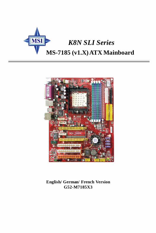
K8N SLI SeriesMS-7185 (v1.X) ATX Mainboard
English/ German/ French VersionG52-M7185X3
7185v1.1-Preface.p65 2005/7/25, 上午 11:351

ii
Copyright Notice
The material in this document is the intellectual property of MICRO-STARINTERNATIONAL. We take every care in the preparation of this document, but noguarantee is given as to the correctness of its contents. Our products are undercontinual improvement and we reserve the right to make changes without notice.
Trademarks
All trademarks are the properties of their respective owners.
NVIDIA, the NVIDIA logo, DualNet, and nForce are registered trademarks or trade-marks of NVIDIA Corporation in the United States and/or other countries.AMD, Athlon™, Athlon™ XP, Thoroughbred™, and Duron™ are registered trade-marks of AMD Corporation.Intel® and Pentium® are registered trademarks of Intel Corporation.PS/2 and OS®/2 are registered trademarks of International Business MachinesCorporation.Windows® 95/98/2000/NT/XP are registered trademarks of Microsoft Corporation.Netware® is a registered trademark of Novell, Inc.Award® is a registered trademark of Phoenix Technologies Ltd.AMI® is a registered trademark of American Megatrends Inc.
Revision History
Revision Revision History DateV1.1 First release for European version July 2005
Technical Support
If a problem arises with your system and no solution can be obtained from the user’smanual, please contact your place of purchase or local distributor. Alternatively,please try the following help resources for further guidance.
Visit the MSI website for FAQ, technical guide, BIOS updates, driver updates,and other information: http://www.msi.com.tw/program/service/faq/faq/esc_faq_list.phpContact our technical staff at: [email protected]
7185v1.1-Preface.p65 2005/7/25, 上午 11:352

iii
Safety Instructions
CAUTION: Danger of explos ion if bat tery is incorrectly replaced.Replace only with the same or equivalent type recommended by themanufacturer.
1. Always read the safety instructions carefully.2. Keep this User’s Manual for future reference.3. Keep this equipment away from humidity.4. Lay this equipment on a reliable f lat surface before setting it up.5. The openings on the enclosure are for air convection hence protects the equip-
ment from overheating. DO NOT COVER THE OPENINGS.6. Make sure the voltage of the power source and adjust properly 110/220V be-
fore connecting the equipment to the power inlet.7. Place the power cord such a way that people can not step on it. Do not place
anything over the power cord.8. Always Unplug the Power Cord before inserting any add-on card or module.9. All cautions and warnings on the equipment should be noted.10. Never pour any liquid into the opening that could damage or cause electrical
shock.11. If any of the following situations arises, get the equipment checked by a service
personnel:Ü The power cord or plug is damaged.Ü Liquid has penetrated into the equipment.Ü The equipment has been exposed to moisture.Ü The equipment has not work well or you can not get it work according to
User’s Manual.Ü The equipment has dropped and damaged.Ü The equipment has obvious sign of breakage.
12. DO NOT LEAVE THIS EQUIPMENT IN AN ENVIRONMENT UNCONDITIONED, STOR-AGE TEMPERATURE ABOVE 600 C (1400F), IT MAY DAMAGE THE EQUIPMENT.
7185v1.1-Preface.p65 2005/7/25, 上午 11:353

iv
FCC-B Radio Frequency Interference Statement
This equipment has beentested and found to complywith the limits for a Class Bdigital device, pursuant to Part15 of the FCC Rules. These limits are designed to provide reasonable protectionagainst harmful interference in a residential installation. This equipment generates,uses and can radiate radio frequency energy and, if not installed and used in accor-dance with the instructions, may cause harmful interference to radio communications.However, there is no guarantee that interference will not occur in a particularinstallation. If this equipment does cause harmful interference to radio or televisionreception, which can be determined by turning the equipment off and on, the user isencouraged to try to correct the interference by one or more of the measures listedbelow.
Ü Reorient or relocate the receiving antenna.
Ü Increase the separation between the equipment and receiver.
Ü Connect the equipment into an outlet on a circuit different from that towhich the receiver is connected.
Ü Consult the dealer or an experienced radio/television technician for help.
Notice 1The changes or modif ications not expressly approved by the party responsible forcompliance could void the user’s authority to operate the equipment.
Notice 2Shielded interface cables and A.C. power cord, if any, must be used in order tocomply with the emission limits.
VOIR LA NOTICE D’INSTALLATION AVANT DE RACCORDER AU RESEAU.
Micro-Star InternationalMS-7185
This device complies with Part 15 of the FCC Rules. Operation is subject to thefollowing two conditions:(1) this device may not cause harmful interference, and(2) this device must accept any interference received, including interference that
may cause undesired operation.
7185v1.1-Preface.p65 2005/7/25, 上午 11:354

v
WEEE (Waste Electrical and Electronic Equipment) Statement
7185v1.1-Preface.p65 2005/7/25, 上午 11:355
vi
7185v1.1-Preface.p65 2005/7/25, 上午 11:356
vii
7185v1.1-Preface.p65 2005/7/25, 上午 11:357

viii
CONTENTSCopyright Notice ............................................................................................................... iiTrademarks ....................................................................................................................... iiRevision History ............................................................................................................... iiTechnical Support ............................................................................................................ iiSafety Instructions .......................................................................................................... iiiFCC-B Radio Frequency Interference Statement ........................................................ ivWEEE (Waste Electrical and Electronic Equipment) Statement .................................... vEnglish ........................................................................................................................ E-1Deutsch ...................................................................................................................... D-1Français ...................................................................................................................... F-1
7185v1.1-Preface.p65 2005/7/25, 上午 11:358

E-1
Quick User’s Guide
K8N SLI Series(MS-7185 v1.X)
ATX Mainboard
English

E-2
MS-7185 ATX Mainboard
E-3
Quick User’s Guide
MS-7185 (v1.X)Quick User’s Guide
Thank you for purchasing the K8N SLI Series (MS-7185 v1.X), anexcellent ATX mainboard from MSI.
Based on the innovative nVIDIA® nForceTM4 SLI chipset for optimalsystem efficiency, the K8N SLI Series mainboards accommodate theadvanced AMD K8 AthlonTM 64 X2 Dual-Core / AthlonTM 64 FX /AthlonTM 64 processors in Socket 939 and support up to four 144-bitDDR DIMMs (at 200, 266, 333, and 400 MHz) to provide the maximumof 4GB memory capacity.
MSI Reminds You...1. Please note that the companion MSI Driver/Utility CD supports
this mainboard with Windows 2000/XP system drivers ONLY.2. To create a bootable RAID volume for a Windows 2000
environment, Microsoft’s Windows 2000 Service Pack 4(SP4) is required. As the end user cannot boot without SP4,a combination installation CD must be created beforeattempting to install the operating system onto the bootableRAID volume.To create the combination installation CD, please refer tothe following website:http://www.microsoft.com/windows2000/downloads/servicepacks/sp4/HFdeploy.htm
E-4
MS-7185 ATX Mainboard
Mainboard Specifications
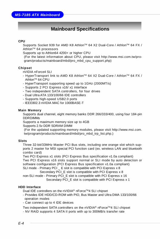
CPUÜ Supports Socket 939 for AMD K8 AthlonTM 64 X2 Dual-Core / AthlonTM 64 FX /
AthlonTM 64 processorsÜ Supports up to Athlon64 4200+ or higher CPU
(For the latest information about CPU, please visit http://www.msi.com.tw/pro-gram/products/mainboard/mbd/pro_mbd_cpu_support.php)
ChipsetÜ nVIDIA nForce4 SLI
- HyperTransport link to AMD K8 AthlonTM 64 X2 Dual-Core / AthlonTM 64 FX /AthlonTM 64 CPU
- HyperTransport supporting speed up to 1GHz (2000MT/s)- Supports 2 PCI Express x16/ x1 interface- Two independent SATA controllers, for four drives- Dual Ultra ATA 133/100/66 IDE controllers- Supports high-speed USB2.0 ports- IEEE802.3 nVIDIA MAC for 1000BASE-T
Main MemoryÜ Supports dual channel, eight memory banks DDR 266/333/400, using four 184-pin
DDR DIMMsÜ Supports a maximum memory size up to 4GBÜ Supports 2.5v DDR SDRAM DIMM
(For the updated supporting memory modules, please visit http://www.msi.com.tw/program/products/mainboard/mbd/pro_mbd_trp_list.php.)
SlotsÜ Three 32-bit/33MHz Master PCI Bus slots, including one orange slot which sup-
ports 2 master for MSI special PCI function card (ex. wireless LAN and bluetoothcombo card)
Ü Two PCI Express x1 slots (PCI Express Bus specification v1.0a compliant)Ü Two PCI Express x16 slots support normal or SLI mode by auto detection or
software configuration (PCI Express Bus specification v1.0a compliant)SLI mode - Primary PCI _ E slot is compatible with PCI Express x 8
Secondary PCI_E slot is compatible with PCI Express x 8non-SLI mode - Primary PCI_E slot is compatible with PCI Express x 16
Secondary PCI_E slot is compatible with PCI Express x 1
HDD InterfaceÜ Dual IDE controllers on the nVIDIA® nForceTM4 SLI chipset
- Provides IDE HDD/CD-ROM with PIO, Bus Master and Ultra DMA 133/100/66operation modes
- Can connect up to 4 IDE devicesÜ Two independent SATA controllers on the nVIDIA® nForceTM4 SLI chipset
- NV RAID supports 4 SATA II ports with up to 300MB/s transfer rate
E-5
Quick User’s Guide
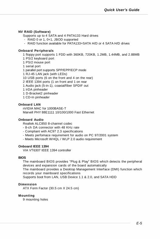
NV RAID (Software)Ü Supports up to 4 SATA and 4 PATA133 Hard drives
- RAID 0 or 1, 0+1, JBOD supported- RAID function available for PATA133+SATA H/D or 4 SATA H/D drives
Onboard PeripheralsÜ 1 floppy port supports 1 FDD with 360KB, 720KB, 1.2MB, 1.44MB, and 2.88MBÜ 1 PS/2 keyboard portÜ 1 PS/2 mouse portÜ 1 serial portÜ 1 parallel port supports SPP/EPP/ECP modeÜ 1 RJ-45 LAN jack (with LEDs)Ü 10 USB ports (6 on the front and 4 on the rear)Ü 2 IEEE 1394 ports (1 on front and 1 on rearÜ 1 Audio jack (5-in-1), coaxial/fiber SPDIF outÜ 1 IrDA pinheaderÜ 1 D-Bracket2 pinheaderÜ 1 CD-In pinheader
Onboard LANÜ nVIDIA MAC for 1000BASE-TÜ Marvell PHY 88E1111 10/100/1000 Fast Ethernet
Onboard AudioÜ Realtek ALC850 8-channel codec
- 8-ch DA connector with 48 KHz rate- Compliant with AC97 2.3 specifications- Meets perfomace requirement for audio on PC 97/2001 system- Meets Microsoft WHQL / WLP 2.0 audio requirement
Onboard IEEE 1394Ü VIA VT6307 IEEE 1394 controller
BIOSÜ The mainboard BIOS provides “Plug & Play” BIOS which detects the peripheral
devices and expansion cards of the board automaticallyÜ The mainboard provides a Desktop Management Interface (DMI) function which
records your mainboard specificationsÜ Supports boot from LAN, USB Device 1.1 & 2.0, and SATA HDD
DimensionÜ ATX Form Factor (30.5 cm X 24.5 cm)
MountingÜ 9 mounting holes
E-6
MS-7185 ATX Mainboard
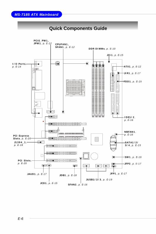
Quick Components Guide
I/O Ports,p. E-14
DDR DIMMs, p. E-10
SFAN2, p. E-16
NBFAN1,p. E-16
CPUFAN1,SFAN1, p. E-12
JIR1, p. E-17
PCIE_PW1,JPW1, p. E-12
SW1, p. E-19
JCI1, p. E-15
JDB1, p. E-18
IDE1/2,p. E-16
JAUD1, p. E-17
FDD1, p. E-15
JUSB1/2/3, p. E-19
PCI ExpressSlots, p. E-20
J1394_1,p. E-18
SATA1/2/3/4, p. E-15
JFP2, p. E-17
JCD1, p. E-15
PCI Slots,p. E-20
JFP1, p. E-17
ATX1, p. E-12
E-7
Quick User’s Guide
Central Processing Unit: CPU
Open Lever
90 degreeSliding Plate
Gold arrow
Gold Arrow
Gold Arrow
Correct CPU placement
O
Incorrect CPU placement
Press down the CPU
Close the lever
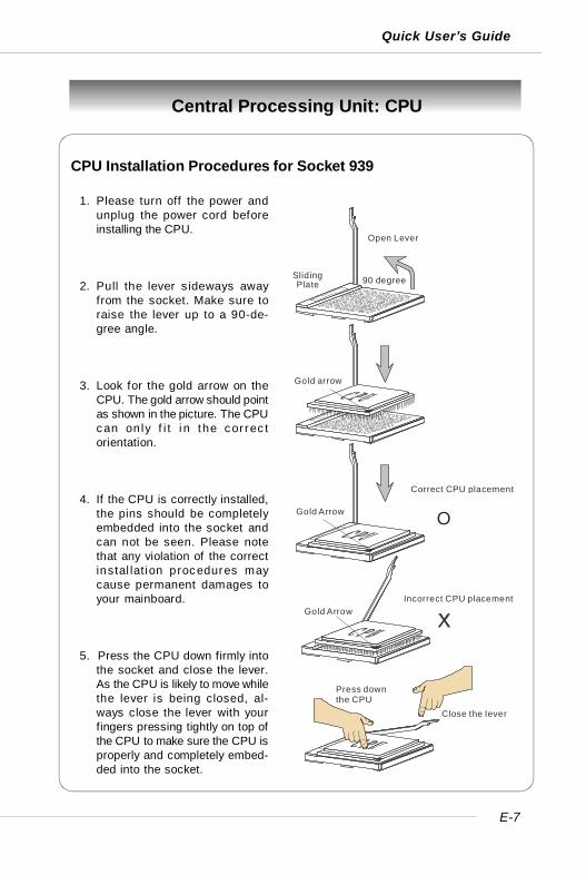
CPU Installation Procedures for Socket 939
1. Please turn off the power andunplug the power cord beforeinstalling the CPU.
2. Pull the lever s ideways awayfrom the socket. Make sure toraise the lever up to a 90-de-gree angle.
3. Look for the gold arrow on theCPU. The gold arrow should pointas shown in the picture. The CPUcan only f i t i n the cor rec torientation.
4. If the CPU is correctly installed,the pins should be completelyembedded into the socket andcan not be seen. Please notethat any violation of the correctinstal lat ion procedures maycause permanent damages toyour mainboard.
5. Press the CPU down firmly intothe socket and close the lever.As the CPU is likely to move whilethe lever is being closed, al-ways close the lever with yourfingers pressing tightly on top ofthe CPU to make sure the CPU isproperly and completely embed-ded into the socket.

E-8
MS-7185 ATX Mainboard
Installing AMD Athlon64 CPU Cooler SetWhen you are installing the CPU, make sure the CPU has a heat sink and acooling fan attached on the top to prevent overheating. If you do not havethe heat sink and cooling fan, contact your dealer to purchase and install thembefore turning on the computer.
1. Detach the shield off thebackplate’s paster.
2. Turn over the mainboard, and installthe backplate to the proper position.
3. Turn over the mainboard again, andplace the mainboard on the flatsurface. Locate the two screwholes of the mainboard.
4. Align the retention mechanism andthe backplate.
Fix the retention mechanism andthe backplate with two screws.
retention mechanism
MSI Reminds You...Mainboard photos shown in this section are for demonstration of thecooler installation for Socket 939 CPUs only. The appearance ofyour mainboard may vary depending on the model you purchase.
E-9
Quick User’s Guide
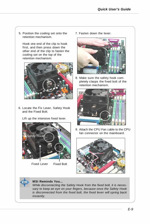
6. Locate the Fix Lever, Safety Hookand the Fixed Bolt.
Lift up the intensive fixed lever.
5. Position the cooling set onto theretention mechanism.
Hook one end of the clip to hookfirst, and then press down theother end of the clip to fasten thecooling set on the top of theretention mechanism.
7. Fasten down the lever.
8. Make sure the safety hook com-pletely clasps the fixed bolt of theretention mechanism.
Safety Hook
Fixed BoltFixed Lever
9. Attach the CPU Fan cable to the CPUfan connector on the mainboard.
MSI Reminds You...While disconnecting the Safety Hook from the fixed bolt, it is neces-sary to keep an eye on your fingers, because once the Safety Hookis disconnected from the fixed bolt, the fixed lever will spring backinstantly.
E-10
MS-7185 ATX Mainboard
Memory
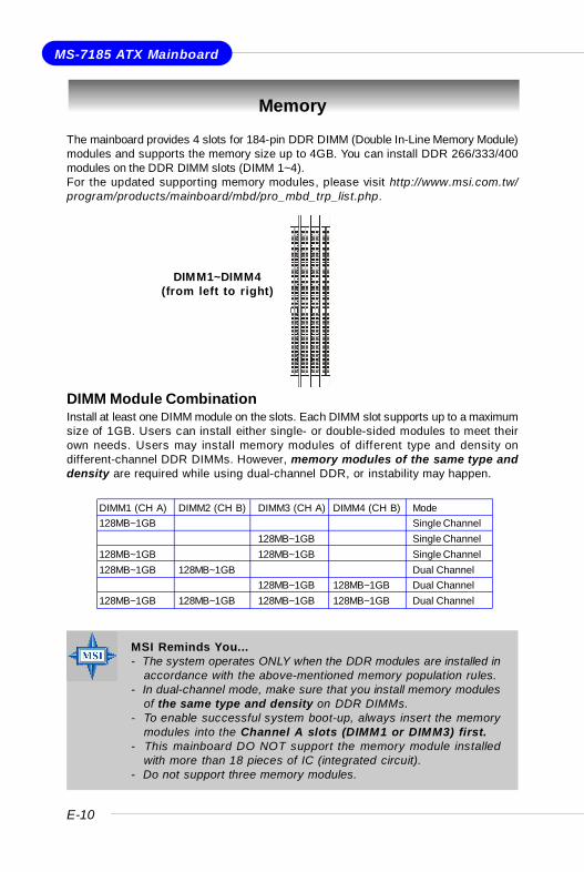
The mainboard provides 4 slots for 184-pin DDR DIMM (Double In-Line Memory Module)modules and supports the memory size up to 4GB. You can install DDR 266/333/400modules on the DDR DIMM slots (DIMM 1~4).For the updated supporting memory modules, please visit http://www.msi.com.tw/program/products/mainboard/mbd/pro_mbd_trp_list.php.
DIMM Module CombinationInstall at least one DIMM module on the slots. Each DIMM slot supports up to a maximumsize of 1GB. Users can install either single- or double-sided modules to meet theirown needs. Users may install memory modules of different type and density ondifferent-channel DDR DIMMs. However, memory modules of the same type anddensity are required while using dual-channel DDR, or instability may happen.
MSI Reminds You...- The system operates ONLY when the DDR modules are installed in
accordance with the above-mentioned memory population rules.- In dual-channel mode, make sure that you install memory modules
of the same type and density on DDR DIMMs.- To enable successful system boot-up, always insert the memory
modules into the Channel A slots (DIMM1 or DIMM3) first.- This mainboard DO NOT support the memory module installed
with more than 18 pieces of IC (integrated circuit).- Do not support three memory modules.
DIMM1~DIMM4(from left to right)
DIMM1 (CH A) DIMM2 (CH B) DIMM3 (CH A) DIMM4 (CH B) Mode128MB~1GB Single Channel
128MB~1GB Single Channel128MB~1GB 128MB~1GB Single Channel128MB~1GB 128MB~1GB Dual Channel
128MB~1GB 128MB~1GB Dual Channel128MB~1GB 128MB~1GB 128MB~1GB 128MB~1GB Dual Channel
E-11
Quick User’s Guide
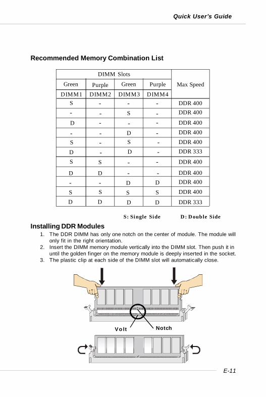
Installing DDR Modules1. The DDR DIMM has only one notch on the center of module. The module will
only fit in the right orientation.2. Insert the DIMM memory module vertically into the DIMM slot. Then push it in
until the golden finger on the memory module is deeply inserted in the socket.3. The plastic clip at each side of the DIMM slot will automatically close.
Volt Notch
Recommended Memory Combination List
S: Single Side D: Double Side
DDR 400DIMM2 DIMM3 DIMM4
S
DIMM Slots
Max Speed
- -S-
D --D-
-S
-
S
DDR 400
DDR 400
DDR 400
DDR 333DDR 400
DDR 400
DDR 400DDR 400
DDR 333
DDR 400
DIMM1-
- --
-
-
SS S S
DD DD
S - S -D - D -
D D - -- - D D
Green GreenPurple Purple
E-12
MS-7185 ATX Mainboard
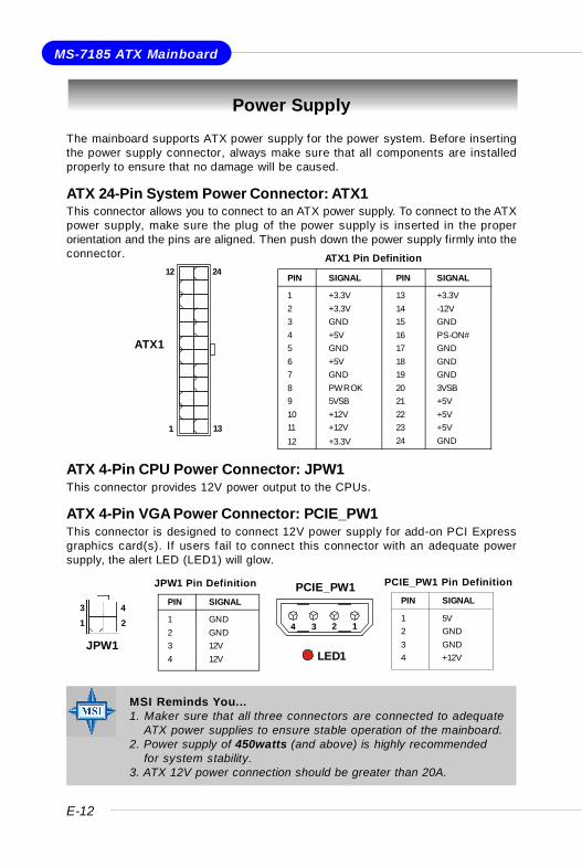
Power Supply
The mainboard supports ATX power supply for the power system. Before insertingthe power supply connector, always make sure that all components are installedproperly to ensure that no damage will be caused.
ATX 24-Pin System Power Connector: ATX1This connector allows you to connect to an ATX power supply. To connect to the ATXpower supply, make sure the plug of the power supply is inserted in the properorientation and the pins are aligned. Then push down the power supply firmly into theconnector.
ATX 4-Pin CPU Power Connector: JPW1This connector provides 12V power output to the CPUs.
ATX 4-Pin VGA Power Connector: PCIE_PW1This connector is designed to connect 12V power supply for add-on PCI Expressgraphics card(s). If users fail to connect this connector with an adequate powersupply, the alert LED (LED1) will glow.
PIN SIGNAL
13 +3.3V14 -12V15 GND16 PS-ON#17 GND18 GND19 GND20 3VSB21 +5V22 +5V23 +5V24 GND
PIN SIGNAL
1 +3.3V2 +3.3V3 GND4 +5V5 GND6 +5V7 GND8 PWR OK9 5VSB10 +12V11 +12V12 +3.3V
ATX1 Pin Definition
PIN SIGNAL
1 GND2 GND3 12V4 12V
JPW1 Pin Definition
MSI Reminds You...1. Maker sure that all three connectors are connected to adequate
ATX power supplies to ensure stable operation of the mainboard.2. Power supply of 450watts (and above) is highly recommended
for system stability.3. ATX 12V power connection should be greater than 20A.
PCIE_PW1
1234
ATX1
12
1 13
24
JPW1
13 4
2
LED1
PIN SIGNAL
1 5V2 GND3 GND4 +12V
PCIE_PW1 Pin Definition
E-13
Quick User’s Guide
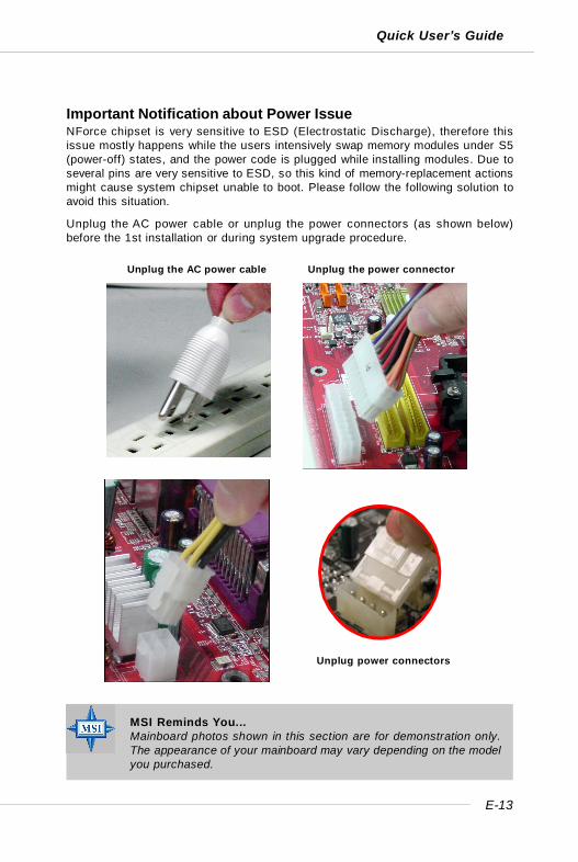
Important Notification about Power IssueNForce chipset is very sensitive to ESD (Electrostatic Discharge), therefore thisissue mostly happens while the users intensively swap memory modules under S5(power-off) states, and the power code is plugged while installing modules. Due toseveral pins are very sensitive to ESD, so this kind of memory-replacement actionsmight cause system chipset unable to boot. Please follow the following solution toavoid this situation.
Unplug the AC power cable or unplug the power connectors (as shown below)before the 1st installation or during system upgrade procedure.
Unplug the AC power cable Unplug the power connector
Unplug power connectors
MSI Reminds You...Mainboard photos shown in this section are for demonstration only.The appearance of your mainboard may vary depending on the modelyou purchased.
E-14
MS-7185 ATX Mainboard
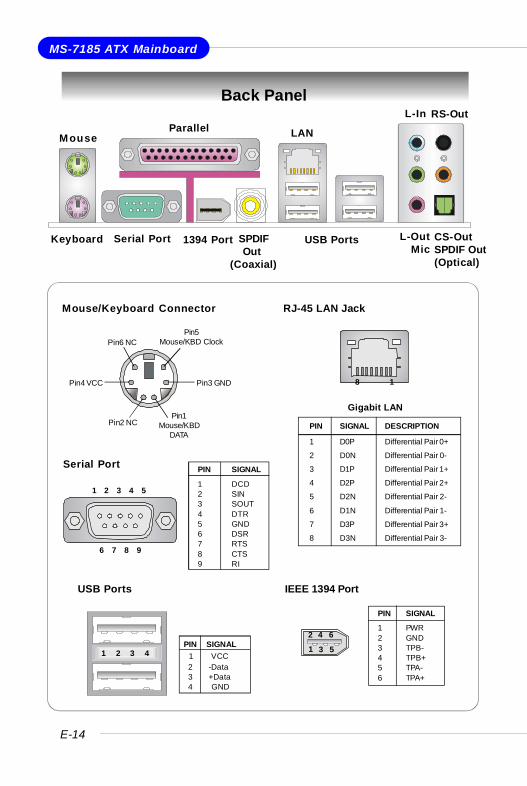
Back Panel
RJ-45 LAN Jack
8 1
Gigabit LAN
PIN SIGNAL DESCRIPTION
1 D0P Differential Pair 0+
2 D0N Differential Pair 0-
3 D1P Differential Pair 1+
4 D2P Differential Pair 2+
5 D2N Differential Pair 2-
6 D1N Differential Pair 1-
7 D3P Differential Pair 3+
8 D3N Differential Pair 3-
Serial Port PIN SIGNAL
1 DCD2 SIN3 SOUT4 DTR5 GND6 DSR7 RTS8 CTS9 RI
1 2 3 4 5
6 7 8 9
USB Ports
1 2 3 4PIN SIGNAL 1 VCC 2 -Data 3 +Data 4 GND
Mouse/Keyboard Connector
Pin1Mouse/KBD
DATAPin2 NC
Pin3 GNDPin4 VCC
Pin5Mouse/KBD ClockPin6 NC
Keyboard Serial Port USB Ports L-OutMic
L-In
MouseParallel LAN
1394 Port SPDIF Out(Coaxial)
RS-Out
CS-OutSPDIF Out(Optical)
IEEE 1394 Port
PIN SIGNAL
1 PWR2 GND3 TPB-4 TPB+5 TPA-6 TPA+
2 4 6
1 3 5
E-15
Quick User’s Guide
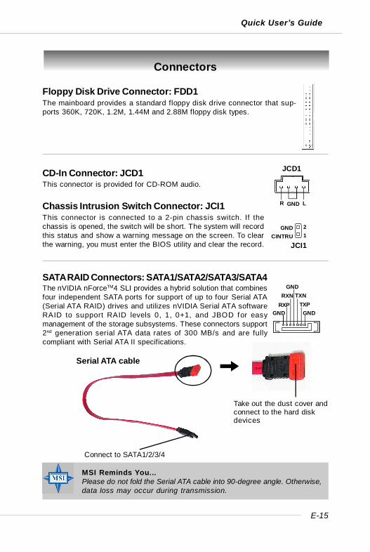
Connectors
Floppy Disk Drive Connector: FDD1The mainboard provides a standard floppy disk drive connector that sup-ports 360K, 720K, 1.2M, 1.44M and 2.88M floppy disk types.
CD-In Connector: JCD1This connector is provided for CD-ROM audio.
JCD1
GNDR L
GNDTXP
TXNGND
RXNRXP
GND
Connect to SATA1/2/3/4
Take out the dust cover andconnect to the hard diskdevices
Serial ATA cable
Chassis Intrusion Switch Connector: JCI1This connector is connected to a 2-pin chassis switch. If thechassis is opened, the switch will be short. The system will recordthis status and show a warning message on the screen. To clearthe warning, you must enter the BIOS utility and clear the record. JCI1
21
GNDCINTRU
MSI Reminds You...Please do not fold the Serial ATA cable into 90-degree angle. Otherwise,data loss may occur during transmission.
SATA RAID Connectors: SATA1/SATA2/SATA3/SATA4The nVIDIA nForceTM4 SLI provides a hybrid solution that combinesfour independent SATA ports for support of up to four Serial ATA(Serial ATA RAID) drives and utilizes nVIDIA Serial ATA softwareRAID to support RAID levels 0, 1, 0+1, and JBOD for easymanagement of the storage subsystems. These connectors support2nd generation serial ATA data rates of 300 MB/s and are fullycompliant with Serial ATA II specifications.
E-16
MS-7185 ATX Mainboard
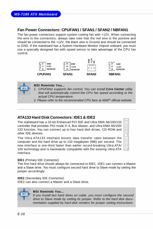
IDE1 (Primary IDE Connector)The first hard drive should always be connected to IDE1. IDE1 can connect a Masterand a Slave drive. You must configure second hard drive to Slave mode by setting thejumper accordingly.
IDE2 (Secondary IDE Connector)IDE2 can also connect a Master and a Slave drive.
MSI Reminds You...If you install two hard disks on cable, you must configure the seconddrive to Slave mode by setting its jumper. Refer to the hard disk docu-mentation supplied by hard disk vendors for jumper setting instructions.
ATA133 Hard Disk Connectors: IDE1 & IDE2The mainboard has a 32-bit Enhanced PCI IDE and Ultra DMA 66/100/133controller that provides PIO mode 0~4, Bus Master, and Ultra DMA 66/100/133 function. You can connect up to four hard disk drives, CD-ROM andother IDE devices.The Ultra ATA133 interface boosts data transfer rates between thecomputer and the hard drive up to 133 megabytes (MB) per second. Thenew interface is one-third faster than earlier record-breaking Ultra ATA/100 technology and is backwards compatible with the existing Ultra ATAinterface.
NBFAN1
+12VGND
SENSOR
CPUFAN1
SENSOR+12VGND
SFAN1
+12VGND
SENSOR
SFAN2
+12V
GN
D
NC
Fan Power Connectors: CPUFAN1 / SFAN1 / SFAN2 / NBFAN1The fan power connectors support system cooling fan with +12V. When connectingthe wire to the connectors, always take note that the red wire is the positive andshould be connected to the +12V, the black wire is Ground and should be connectedto GND. If the mainboard has a System Hardware Monitor chipset onboard, you mustuse a specially designed fan with speed sensor to take advantage of the CPU fancontrol.
MSI Reminds You...1. CPUFAN1 supports fan control. You can install Core Center utility
that will automatically control the CPU fan speed according to theactual CPU temperature.
2. Please refer to the recommended CPU fans at AMD® official website.
E-17
Quick User’s Guide
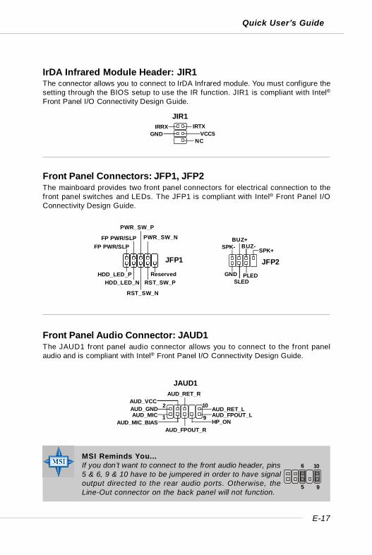
Front Panel Connectors: JFP1, JFP2The mainboard provides two front panel connectors for electrical connection to thefront panel switches and LEDs. The JFP1 is compliant with Intel® Front Panel I/OConnectivity Design Guide.
MSI Reminds You...If you don’t want to connect to the front audio header, pins5 & 6, 9 & 10 have to be jumpered in order to have signaloutput directed to the rear audio ports. Otherwise, theLine-Out connector on the back panel will not function.
Front Panel Audio Connector: JAUD1The JAUD1 front panel audio connector allows you to connect to the front panelaudio and is compliant with Intel® Front Panel I/O Connectivity Design Guide.
JAUD1
1
2
9
10AUD_MIC
AUD_GND
AUD_MIC_BIAS
AUD_VCC
AUD_FPOUT_R
AUD_RET_R
HP_ONAUD_FPOUT_LAUD_RET_L
5
6 10
9
IrDA Infrared Module Header: JIR1The connector allows you to connect to IrDA Infrared module. You must configure thesetting through the BIOS setup to use the IR function. JIR1 is compliant with Intel®Front Panel I/O Connectivity Design Guide.
JFP1
HDD_LED_PHDD_LED_N
RST_SW_N
RST_SW_PReserved
FP PWR/SLPFP PWR/SLP
PWR_SW_P
PWR_SW_N
GND
JFP2
SLEDPLED
SPK-BUZ+
BUZ-SPK+
JIR1IRTXIRRX
VCC5NC
GND
E-18
MS-7185 ATX Mainboard
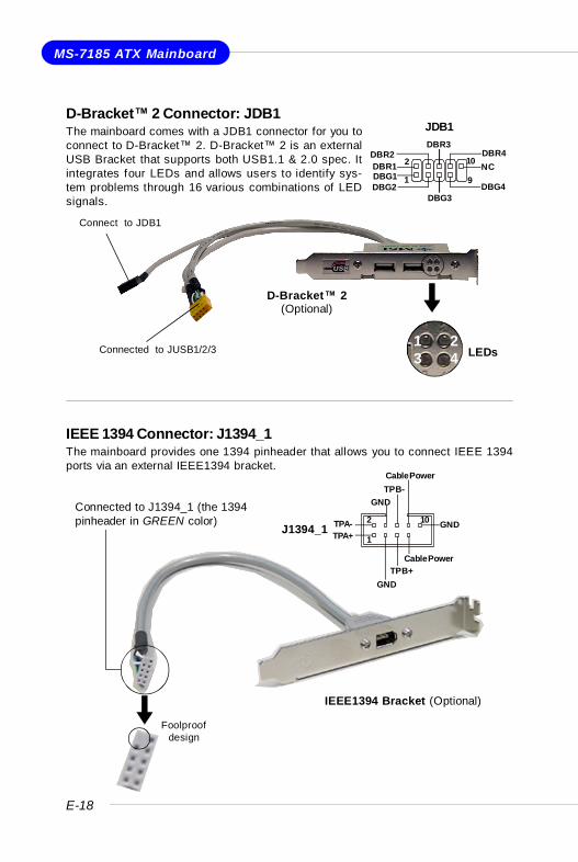
D-Bracket™ 2 Connector: JDB1The mainboard comes with a JDB1 connector for you toconnect to D-Bracket™ 2. D-Bracket™ 2 is an externalUSB Bracket that supports both USB1.1 & 2.0 spec. Itintegrates four LEDs and allows users to identify sys-tem problems through 16 various combinations of LEDsignals.
IEEE 1394 Connector: J1394_1The mainboard provides one 1394 pinheader that allows you to connect IEEE 1394ports via an external IEEE1394 bracket.
D-Bracket™ 2(Optional)
Connect to JDB1
LEDsConnected to JUSB1/2/31 23 4
Foolproofdesign
Connected to J1394_1 (the 1394pinheader in GREEN color)
IEEE1394 Bracket (Optional)
JDB1
1
2
9
10
DBG1DBR1
DBG2
DBR2
DBG3
DBR3
DBG4
DBR4NC
J1394_11
2 10
TPA+TPA-
GND
GND
TPB+
TPB-
Cable Power
GND
Cable Power
E-19
Quick User’s Guide
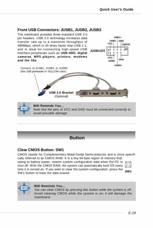
Front USB Connectors: JUSB1, JUSB2, JUSB3The mainboard provides three standard USB 2.0pin headers. USB 2.0 technology increases datatransfer rate up to a maximum throughput of480Mbps, which is 40 times faster than USB 1.1,and is ideal for connecting high-speed USBinterface peripherals such as USB HDD, digitalcameras, MP3 players, printers, modemsand the like.
MSI Reminds You...Note that the pins of VCC and GND must be connected correctly toavoid possible damage.
Clear CMOS Button: SW1CMOS stands for Complementary Metal-Oxide Semiconductor and is more specifi-cally referred to as CMOS RAM. It is a tiny 64-byte region of memory that,owing to battery power, retains system configuration data when the PC isshut off. With the CMOS RAM, the system can automatically boot OS everytime it is turned on. If you want to clear the system configuration, press theSW1 button to have the data erased.
Button
MSI Reminds You...You can clear CMOS by pressing this button while the system is off.Avoid clearing CMOS while the system is on; it will damage themainboard.
JUSB1/2/3
VCCUSB0-
USB0+
GND
VCCUSB1-
USB1+GND
USBOC
1 2 10
Connect to JUSB1, JUSB2, or JUSB3(the USB pinheader in YELLOW color)
USB 2.0 Bracket(Optional)
SW1
E-20
MS-7185 ATX Mainboard
Slots
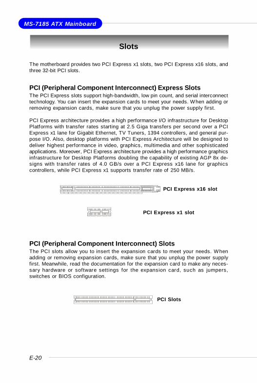
The motherboard provides two PCI Express x1 slots, two PCI Express x16 slots, andthree 32-bit PCI slots.
PCI (Peripheral Component Interconnect) Express SlotsThe PCI Express slots support high-bandwidth, low pin count, and serial interconnecttechnology. You can insert the expansion cards to meet your needs. When adding orremoving expansion cards, make sure that you unplug the power supply first.
PCI Express architecture provides a high performance I/O infrastructure for DesktopPlatforms with transfer rates starting at 2.5 Giga transfers per second over a PCIExpress x1 lane for Gigabit Ethernet, TV Tuners, 1394 controllers, and general pur-pose I/O. Also, desktop platforms with PCI Express Architecture will be designed todeliver highest performance in video, graphics, multimedia and other sophisticatedapplications. Moreover, PCI Express architecture provides a high performance graphicsinfrastructure for Desktop Platforms doubling the capability of existing AGP 8x de-signs with transfer rates of 4.0 GB/s over a PCI Express x16 lane for graphicscontrollers, while PCI Express x1 supports transfer rate of 250 MB/s.
PCI (Peripheral Component Interconnect) SlotsThe PCI slots allow you to insert the expansion cards to meet your needs. Whenadding or removing expansion cards, make sure that you unplug the power supplyfirst. Meanwhile, read the documentation for the expansion card to make any neces-sary hardware or software sett ings for the expansion card, such as jumpers,switches or BIOS configuration.
PCI Slots
PCI Express x1 slot
PCI Express x16 slot

E-21
Quick User’s Guide
PCI Interrupt Request RoutingThe IRQ, acronym of interrupt request line and pronounced I-R-Q, are hardware linesover which devices can send interrupt signals to the microprocessor. The PCI IRQpins are typically connected to the PCI bus pins as follows:
NV SLI (Scalable Link Interface) Slot: PCI_E4NVIDIA SLI (Scalable Link Interface) technology allows two GPUs to run in tandemwithin a system to achieve up to twice the performance of a single graphics card. Toutilize this technology, the two GPU cards must beconnected by an SLI bridge card.You can find an SLI switch card on the mainboardconfigured to non-SLI mode by default.
MSI Reminds You...Make sure that you unplug the power supply before removing the SLIswitch card.
If you intend to use the SLI interface for better graphics performance, please refer tothe following instructions.
1. Push the retaining clips (on the sides of the SLI slot) outwards to release theSLI switch card.
SLI Bridge Card
Order 1 Order 2 Order 3 Order 4
PCI Slot 1 INT A# INT B# INT C# INT D#
PCI Slot 2 INT B# INT C# INT D# INT A#
PCI Slot 3 INT C# INT D# INT A# INT B#
SLI Switch Card
non-SLI mode
E-22
MS-7185 ATX Mainboard
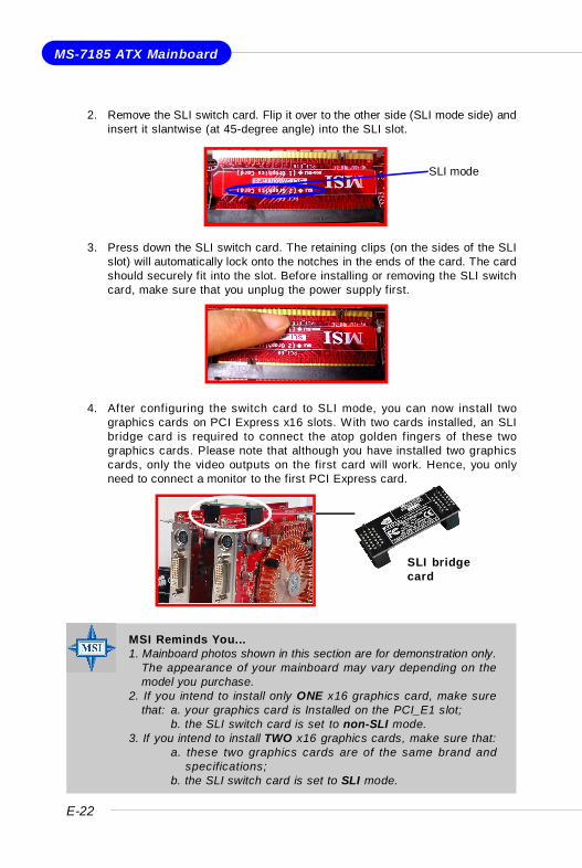
2. Remove the SLI switch card. Flip it over to the other side (SLI mode side) andinsert it slantwise (at 45-degree angle) into the SLI slot.
3. Press down the SLI switch card. The retaining clips (on the sides of the SLIslot) will automatically lock onto the notches in the ends of the card. The cardshould securely fit into the slot. Before installing or removing the SLI switchcard, make sure that you unplug the power supply first.
MSI Reminds You...1. Mainboard photos shown in this section are for demonstration only.
The appearance of your mainboard may vary depending on themodel you purchase.
2. If you intend to install only ONE x16 graphics card, make surethat: a. your graphics card is Installed on the PCI_E1 slot;
b. the SLI switch card is set to non-SLI mode.3. If you intend to install TWO x16 graphics cards, make sure that:
a. these two graphics cards are of the same brand andspecifications;
b. the SLI switch card is set to SLI mode.
SLI bridgecard
4. After configuring the switch card to SLI mode, you can now install twographics cards on PCI Express x16 slots. With two cards installed, an SLIbridge card is required to connect the atop golden f ingers of these twographics cards. Please note that although you have installed two graphicscards, only the video outputs on the first card will work. Hence, you onlyneed to connect a monitor to the first PCI Express card.
SLI mode
E-23
Quick User’s Guide
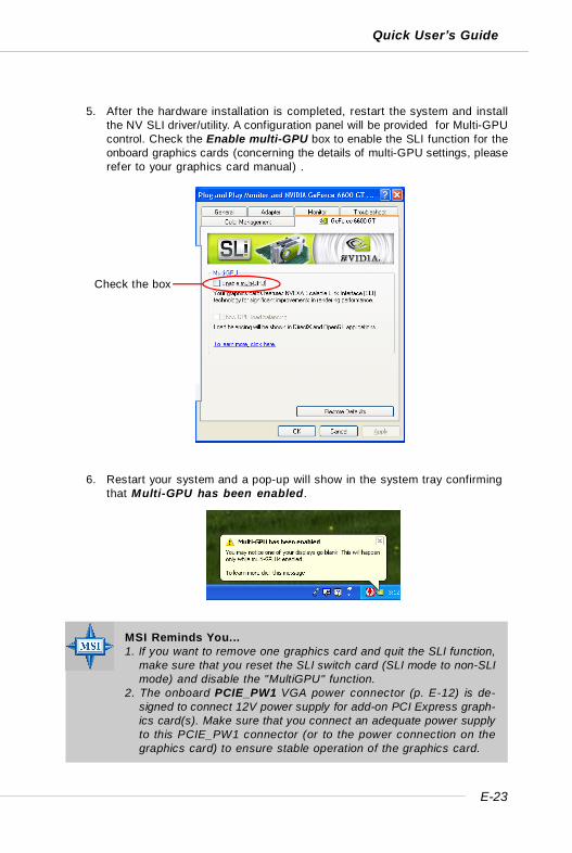
5. After the hardware installation is completed, restart the system and installthe NV SLI driver/utility. A configuration panel will be provided for Multi-GPUcontrol. Check the Enable multi-GPU box to enable the SLI function for theonboard graphics cards (concerning the details of multi-GPU settings, pleaserefer to your graphics card manual) .
6. Restart your system and a pop-up will show in the system tray confirmingthat Multi-GPU has been enabled.
Check the box
MSI Reminds You...1. If you want to remove one graphics card and quit the SLI function,
make sure that you reset the SLI switch card (SLI mode to non-SLImode) and disable the "MultiGPU" function.
2. The onboard PCIE_PW1 VGA power connector (p. E-12) is de-signed to connect 12V power supply for add-on PCI Express graph-ics card(s). Make sure that you connect an adequate power supplyto this PCIE_PW1 connector (or to the power connection on thegraphics card) to ensure stable operation of the graphics card.
E-24
MS-7185 ATX Mainboard
BIOS Setup
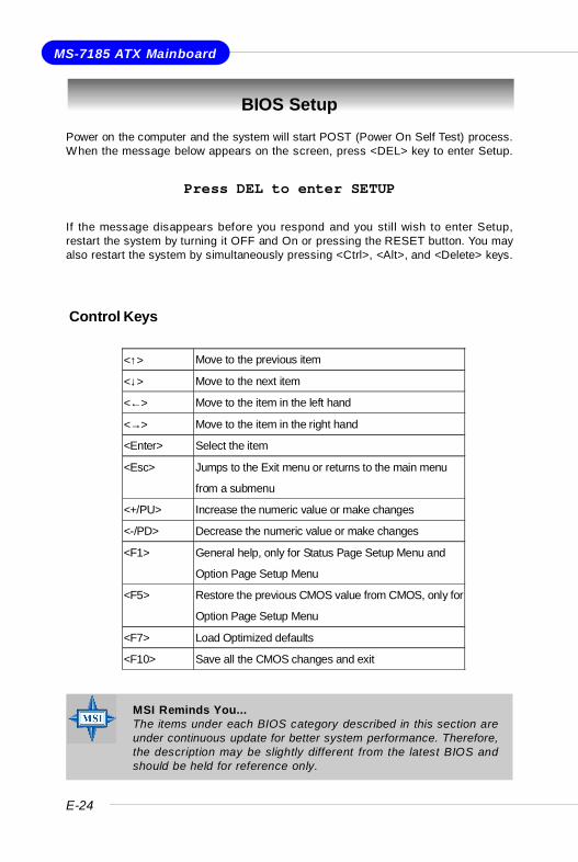
Control Keys
MSI Reminds You...The items under each BIOS category described in this section areunder continuous update for better system performance. Therefore,the description may be slightly different from the latest BIOS andshould be held for reference only.
Power on the computer and the system will start POST (Power On Self Test) process.When the message below appears on the screen, press <DEL> key to enter Setup.
Press DEL to enter SETUP
If the message disappears before you respond and you still wish to enter Setup,restart the system by turning it OFF and On or pressing the RESET button. You mayalso restart the system by simultaneously pressing <Ctrl>, <Alt>, and <Delete> keys.
<↑> Move to the previous item
<↓> Move to the next item
<←> Move to the item in the left hand
<→> Move to the item in the right hand
<Enter> Select the item
<Esc> Jumps to the Exit menu or returns to the main menu
from a submenu
<+/PU> Increase the numeric value or make changes
<-/PD> Decrease the numeric value or make changes
<F1> General help, only for Status Page Setup Menu and
Option Page Setup Menu
<F5> Restore the previous CMOS value from CMOS, only for
Option Page Setup Menu
<F7> Load Optimized defaults
<F10> Save all the CMOS changes and exit
E-25
Quick User’s Guide
The Main Menu
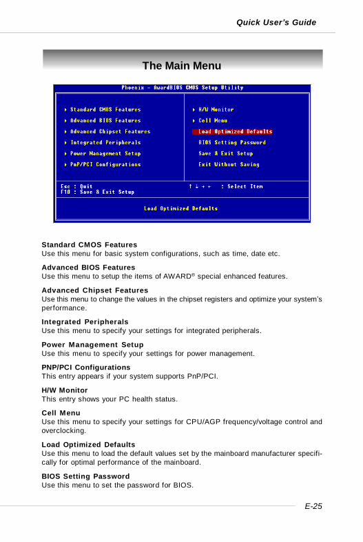
Standard CMOS FeaturesUse this menu for basic system configurations, such as time, date etc.
Advanced BIOS FeaturesUse this menu to setup the items of AWARD® special enhanced features.
Advanced Chipset FeaturesUse this menu to change the values in the chipset registers and optimize your system’sperformance.
Integrated PeripheralsUse this menu to specify your settings for integrated peripherals.
Power Management SetupUse this menu to specify your settings for power management.
PNP/PCI ConfigurationsThis entry appears if your system supports PnP/PCI.
H/W MonitorThis entry shows your PC health status.
Cell MenuUse this menu to specify your settings for CPU/AGP frequency/voltage control andoverclocking.
Load Optimized DefaultsUse this menu to load the default values set by the mainboard manufacturer specifi-cally for optimal performance of the mainboard.
BIOS Setting PasswordUse this menu to set the password for BIOS.
E-26
MS-7185 ATX Mainboard
Cell Menu
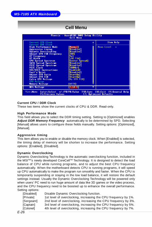
Current CPU / DDR ClockThese two items show the current clocks of CPU & DDR. Read-only.
High Performance ModeThis field allows you to select the DDR timing setting. Setting to [Optimized] enablesAdjust DDR Memory Frequency automatically to be determined by SPD. Selecting[Manual] allows users to configure these fields manually. Setting options: [Optimized],[Manual].
Aggressive timingThis item allows you to enable or disable the memory clock. When [Enabled] is selected,the timing delay of memory will be shorten to increase the performance. Settingoptions: [Enabled], [Disabled].
Dynamic OverclockingDynamic Overclocking Technology is the automatic overclocking function, included inthe MSITM’s newly developed CoreCellTM Technology. It is designed to detect the loadbalance of CPU while running programs, and to adjust the best CPU frequencyautomatically. When the motherboard detects CPU is running programs, it will speedup CPU automatically to make the program run smoothly and faster. When the CPU istemporarily suspending or staying in the low load balance, it will restore the defaultsettings instead. Usually the Dynamic Overclocking Technology will be powered onlywhen users' PC need to run huge amount of data like 3D games or the video process,and the CPU frequency need to be boosted up to enhance the overall performance.Setting options:
[Disabled] Disable Dynamic Overclocking function.[Private] 1st level of overclocking, increasing the CPU frequency by 1%.[Sergeant] 2nd level of overclocking, increasing the CPU frequency by 3%.[Captain] 3rd level of overclocking, increasing the CPU frequency by 5%.[Colonel] 4th level of overclocking, increasing the CPU frequency by 7%.
E-27
Quick User’s Guide
[General] 5th level of overclocking, increasing the CPU frequency by 9%.[Commander] 6th level of overclocking, increasing the CPU frequency by 11%.
Adjust CPU FSB FrequencyThis item allows you to select the CPU Front Side Bus clock frequency (in MHz).Select the number between [200]~[400] for needed frequency.
HT FrequencyThis setting specifies the maximum operating frequency of the link’s transmitter clock.Setting options: [1x], [1.5x], [2x], [2.5x], [3x], [4x], [5x].
HT WidthThis field allows you to set the HT Width between CPU & Chip.↑ mark means Chip toCPU HT Width. And ↓ mark means CPU to Chip HT Width. Setting options: [ ↓ 8 ↑ 8], [↓ 16 ↑ 8], [↓ 8 ↑16], [ ↓16 ↑16].
CPU Spread SpectrumThis setting is used to enable or disable the CPU Spread Spectrum feature. Whenoverclocking the CPU, always set it to [Disabled]. Setting options: [Center Spread],[Disabled].
SATA Spread SpectrumThis setting is used to enable or disable the SATA Spread Spectrum feature. Whenoverclocking the CPU, always set it to [Disabled]. Setting options: [Disabled], [DownSpread].
PCIE Spread SpectrumThis setting is used to enable or disable the PCI Express Spread Spectrum feature.When overclocking the CPU, always set it to [Disabled]. Setting options: [Disabled],[Down Spread].
PCIE ClockThis item allows you to select the PCIE Bus clock frequency (in MHz). Select thenumber between [100]~[145] for needed frequency.
SSE/ SSE2 InstructionsThis setting disables/enables the SSE/SSE2 Instructions. The Streaming SIMD Exten-sions (SSE) were introduced in the Pentium III processor. The SSE extensions con-sist of a new set of instructions and a new set of registers. These instructions andregisters are designed to allow Single-Instruction Multiple-Data (SIMD) computationsto be made on single-precision floating-point numbers.The Streaming SIMD Extensions 2 (SSE2) were introduced in the Pentium 4 and Intel
MSI Reminds You...Even though the Dynamic Overclocking Technology is more stablethan manual overclocking, basically, it is still risky. Users are sug-gested to check their CPU’s overclocking capability first. If the PCappears to be unstable or reboot incidentally, it's better to disableDynamic Overclocking or to lower the level of overclocking options.By the way, if you need to conduct overclocking manually, you alsoneed to disable Dynamic Overclocking first.
E-28
MS-7185 ATX Mainboard
Xeon processors. They consist of a new set of instructions that operate on the XXMand MXCSR registers and perform SIMD operations on double-precision floating-point values and on integer values.Several of these new SSE/SSE2 instructions alsooperate in the MMX registers. Setting options: [Enabled], [Disabled].
Cool’n’QuietThis feature is especially designed for AMD Athlon processor, which provides a CPUtemperature detecting function to prevent your CPU’s from overheating due to theheavy working loading. Setting options: [Disabled], [Auto].
Adjust CPU RatioThis item lets you adjust the CPU ratio. Setting to [Startup] enables the CPU runningat the fastest speed which is detected by system. Setting options are: [Startup],[x4]~[x25].
Adjust CPU VIDThis item lets you adjust the CPU VID. Setting to [Startup] enables the CPU runningat the default VID which is detected by system. Setting options are: [Startup], [0.825V], [0.850V],[0.875V],~, [1.550V].
Extra CPU VoltageThis feature allows you to add extra voltage to the CPU. Setting options are: [ByCPU VID], [Over VID 3.3%], [Over VID 6.6%],[Over VID 8.3%].
CPU VoltageThis setting shows the voltage of the CPU.
Memory VoltageAdjusting the DDR voltage can increase the DDR speed. Any changes made to thissetting may cause a stability issue, so changing the DDR voltage for long-termpurpose is NOT recommended. Setting options: [Auto], [2.50V] ~ [2.85V].
NF4 VoltageNF4 voltage is adjustable in the field. Setting options: [1.50V] ~ [1.85V].
MSI Reminds You...For the purpose of ensuring the stability of Cool'n'Quiet function, it isalways recommended to have the memories plugged in DIMM1.
MSI Reminds You...The settings shown in different color in CPU Voltage, MemoryVoltage and NF4 Voltage help to verify if your setting is proper foryour system.Gray: Default setting.Yellow: High performance setting.Red: Not recommended setting and the system may be
unstable.Changing CPU Voltage, Memory Voltage and NF4 Voltage mayresult in the instability of the system; therefore, it is NOT recom-mended to change the default setting for long-term usage.

D-1
Kurzanleitung
K8N SLI Series(MS-7185 V1.X)
ATX Mainboard
Deutsch

D-2
MS-7185 ATX Mainboard
D-3
Kurzanleitung
MS-7185 (V1.X)Kurzanleitung
Danke, dass Sie mit das ATX Mainboard K8N SLI Series (MS-7185V1.X), ein exzellentes Mainboard von MSI, erworben haben.
Aufbauend auf dem innovativen nVIDIA® nForceTM4 SLI Chipsatzfür ein optimales und effizientes System, nimmt das K8N SLI Seriesdie fortschrittlichen AMD K8 AthlonTM 64 X2 Dual-Core / AthlonTM
64 FX / AthlonTM 64 Prozessoren im Sockel 939 auf und unterstütztbis zu vier 144-bit DDR DIMMs (mit 200, 266, 333 und 400 MHz) -womit es einen maximalen Speicherausbau auf bis zu 4GB ermöglicht.
MSI weist darauf hin...1. Beachten Sie bitte, dass die beigelegte MSI Treiber/Utility CD
AUSCHLIESSLICH dieses Mainboard mit Windows 2000/XPSystemtreibern unterstützt.
2. Um ein bootfähiges RAID Laufwerk unter Windows 2000 zuerzeugen, wird Microsoft’s Windows 2000 Service Pack 4(SP4) benötigt. Da der Endanwender nicht ohne SP4 bootenkann, muss eine kombinierte Installations- CD erstelltwerden, bevor der Versuch unternommen werden kann, dasBetriebssystem auf ein bootfähiges RAID Laufwerk zuinstallieren.Entnehmen Sie bitte folgender Website, wie Sie einekombinierte Installations- CD erstellen:http://www.microsoft.com/windows2000/downloads/servicepacks/sp4/HFdeploy.htm
D-4
MS-7185 ATX Mainboard
Mainboard SpezifikationenCPUÜ Unterstützt den Sockel 939 für AMD K8 AthlonTM 64 X2 Dual-Core / AthlonTM 64 FX
/ AthlonTM 64 ProzessorenÜ Unterstützt CPUs bis hin zum Athlon64 4200+ oder höher
(Die neuesten Informationen zu unterstützten Prozessoren finden Sie unter http://www.msi.com.tw/program/products/mainboard/mbd/pro_mbd_cpu_support.php)
ChipsatzÜ nVIDIA nForce4 SLI
- HyperTransport Anbindung an AMD K8 AthlonTM 64 X2 Dual-Core / AthlonTM 64 FX/ AthlonTM 64 CPU
- HyperTransport unterstützt Geschwindigkeiten von bis zu 1GHz (2000MT/s)- Unterstützt 2 PCI Express x16/ x1 Schnittstellen- Zwei unabhängige SATA Kontroller, für vier Laufwerke- Dual Ultra ATA 133/100/66 IDE Kontroller- Unterstützt Hochgeschwindigkeits- USB2.0 Ports- IEEE802.3 nVIDIA MAC für 1000BASE-T
HauptspeicherÜ Unterstützt acht Zweikanal DDR 266/333/400 Speicherbänke für vier 184-pin
DDR DIMMsÜ Unterstützt einen maximalen Speicherausbau auf bis zu 4GBÜ Unterstützt 2,5V DDR SDRAM DIMMs
(Um den letzten Stand bezüglich der unterstützten Speichermodule zu erhalten,besuchen Sie bitte http://www.msi.com.tw/program/products/mainboard/mbd/pro_mbd_trp_list.php.)
SteckplätzeÜ Drei 32-bit/33Mhz Master PCI Bus Slots, einschließlich eines orangefarbenen,
der 2 Master für MSI PCI Karten mit Spezialfunktion bereit stellt (z.B. WirelessLAN und Bluetooth Kombikarte)
Ü Zwei PCI Express x1 Slots (erfüllen die PCI Express Bus Spezifikation V1.0a)Ü Zwei PCI Express x16 Sockel, die durch automatische Erkennung oder über
Softwareeinstellung zwischen Normal und dem SLI Betrieb umschaltbar sind(erfüllen die PCI Express Bus Spezifikation V1.0a)SLI Modus - Primärer PCI _ E Slot ist kompatibel mit PCI Express x 8
- Sekundärer PCI_E Slot ist kompatibel mit PCI Express x 8Normaler Modus - Primärer PCI_E Slot ist kompatibel mit PCI Express x 16
- Sekundärer PCI_E Slot ist kompatibel mit PCI Express x 1
FestplattenschnittstellenÜ Dual IDE Kontroller im nVIDIA® nForceTM4 SLI Chipsatz enthalten
- Bietet IDE HDD/CD-ROM Zugriff mit den Betriebsmodi PIO, Bus Mastering undUltra DMA 133/100/66
- Bis zu vier IDE Geräte anschließbarÜ Zwei unabhängige SATA Kontroller im nVIDIA® nForceTM4 SLI Chipsatz enthalten
- NV RAID unterstützt 4 SATA II Ports mit Übertragungsraten von bis zu 300MB/s
D-5
Kurzanleitung
NV RAID (Software)Ü Unterstützt bis zu 4 SATA und 4 PATA133 Festplatten
- Bietet RAID 0 oder 1, 0+1, sowie JBOD ( Betrieb ohne Raid- Funktionalität)- RAID Funktionalität verfügbar für PATA133+SATA Festplatten oder 4 SATA
Festplatten
Peripherieanschlüsse onboardÜ 1 Anschluss für 1 Diskettenlaufwerk mit 360 KB, 720 KB, 1,2 MB, 1,44 MB oder
2,88 MBÜ 1 PS/2 TastaturanschlussÜ 1 PS/2 MausanschlussÜ 1 Serielle SchnittstelleÜ 1 Parallele Schnittstelle, die die Betriebsmodi SPP/EPP/ECP unterstütztÜ 1 RJ-45 Port (mit LEDs)Ü 10 USB Anschlüsse (6 vordere und 4 hintere)Ü 2 IEEE 1394 (1 vordere und 1 hintere)Ü 1 Audio Buchse (5-in-1), koaxial/Glasfaser SPDIF AusgangÜ 1 IrDA StiftleisteÜ 1 D-Bracket 2 StiftleistenanschlussÜ 1 CD-Eingang als Stiftleiste
Onboard LANÜ nVIDIA MAC für 1000BASE-TÜ Marvell PHY 88E1111 10/100/1000 Fast Ethernet
Onboard AudioÜ Realtek ALC850 8-Kanal Codec
- 8-Kanal DA Anschluss mit 48 KHz- Erfüllt die Spezifikation AC97 2.3- Erfüllt die Audioleistungsanforderungen an Systeme gemäß PC 97/2001- Erfüllt die Microsoft WHQL / WLP 2.0 Audioanforderungen
Onboard IEEE 1394Ü VIA VT6307 IEEE 1394 Kontroller
BIOSÜ Das Mainboard- BIOS verfügt über “Plug & Play”- Funktionalität, mit der ange-
schlossene Peripheriegeräte und Erweiterungskarten automatisch erkanntwerden.
Ü Das Mainboard stellt ein Desktop - Management - Interface (DMI) zur Verfügung,welches automatisch die Spezifikationen Ihres Mainboards aufzeichnet.
Ü Unterstützt das Hochfahren aus dem Netzwerk, von USB 1.1 und 2.0 Geräten undSATA Festplatten
AbmessungenÜ ATX Form Faktor (30,5 cm X 24,5 cm)
MontageÜ 9 Montagebohrungen
D-6
MS-7185 ATX Mainboard
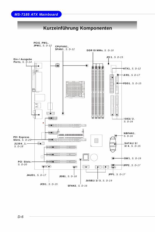
Kurzeinführung Komponenten
DDR DIMMs, S. D-10
SFAN2, S. D-16
NBFAN1,S. D-16
CPUFAN1,SFAN1, S. D-12
JIR1, S. D-17
PCIE_PW1,JPW1, S. D-12
SW1, S. D-19
JCI1, S. D-15
JDB1, S. D-18
IDE1/2,S. D-16
JAUD1, S. D-17
FDD1, S. D-15
JUSB1/2/3, S. D-19
PCI ExpressSlots, S. D-20
J1394_1,S. D-18
SATA1/2/3/4, S. D-15
JFP2, S. D-17
JCD1, S. D-15
PCI Slots,S. D-20
JFP1, S. D-17
ATX1, S. D-12
Ein-/AusgabePorts, S. D-14
D-7
Kurzanleitung
Hauptprozessor: CPU
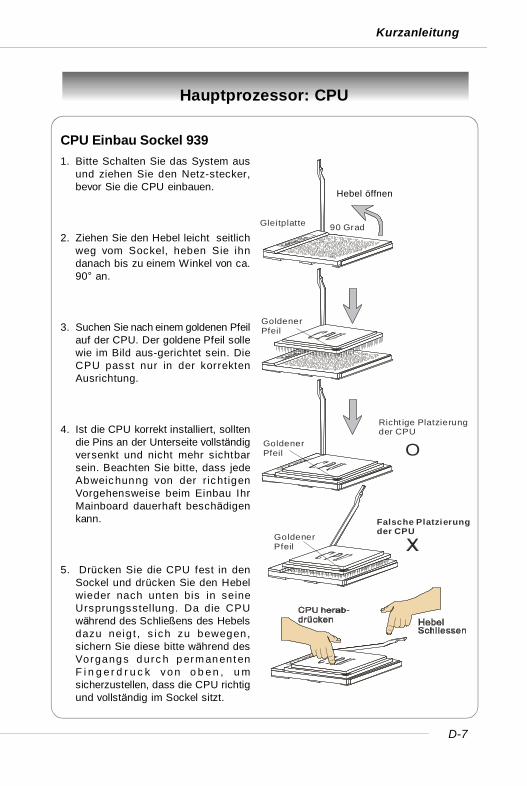
CPU Einbau Sockel 9391. Bitte Schalten Sie das System aus
und ziehen Sie den Netz-stecker,bevor Sie die CPU einbauen.
2. Ziehen Sie den Hebel leicht seitlichweg vom Sockel, heben Sie ihndanach bis zu einem Winkel von ca.90° an.
3. Suchen Sie nach einem goldenen Pfeilauf der CPU. Der goldene Pfeil sollewie im Bild aus-gerichtet sein. DieCPU passt nur in der korrektenAusrichtung.
4. Ist die CPU korrekt installiert, solltendie Pins an der Unterseite vollständigversenkt und nicht mehr sichtbarsein. Beachten Sie bitte, dass jedeAbweichunng von der r ichtigenVorgehensweise beim Einbau IhrMainboard dauerhaft beschädigenkann.
5. Drücken Sie die CPU fest in denSockel und drücken Sie den Hebelwieder nach unten bis in seineUrsprungsstellung. Da die CPUwährend des Schließens des Hebelsdazu neig t , s ich zu bewegen,sichern Sie diese bitte während desVorgang s d urc h p erman ent enF i n g e r d r u c k vo n o b e n , u msicherzustellen, dass die CPU richtigund vollständig im Sockel sitzt.
Hebel 鐪fnen
90 GradGleitplatte
GoldenerPfeil
GoldenerPfeil
GoldenerPfeil
Richt ige Platzierungder CPU
Falsche Platzierungder CPU
O
Hebel öffnen
D-8
MS-7185 ATX Mainboard
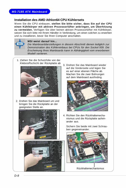
Installation des AMD Athlon64 CPU KühlersetsW enn Sie die CPU einbauen, stellen Sie bitte sicher, dass Sie auf der CPUeinen Kühlkörper mit aktiven Prozessorlüfter anbringen, um Überhitzungzu vermeiden. Verfügen Sie über keinen aktiven Prozessorlüfter mit Kühlkörper,setzen Sie sich bitte mit Ihrem Händler in Verbindung, um einen solchen zu erwerbenund zu installieren, bevor Sie Ihren Computer anschalten.
1. Ziehen Sie die Schutzfolie von derKlebstoffschicht der Rückplatte ab
2. Drehen Sie das Mainboard um undbringen Sie die Rückplatte an dergeeigneten Stelle an.
3. Drehen Sie das Mainboard wiederauf die Vorderseite und legen Siees auf einer ebenen Fläche ab.Machen Sie die zwei Bohrungenauf dem Mainboard ausfinding.
4. Richten Sie den Rückhaltemecha-nismus und die Rückplatte aufein-ander aus.
Sichern Sie beide mit zwei Schrau-ben gegeneinander.
Rückhaltemechanismus
MSI weist darauf hin...Die Mainboarddarstellungen in diesem Abschnitt dienen lediglich zurDemonstration des Kühlereinbaus bei CPUs für den Sockel 939. DieErscheinung Ihres Mainboards kann in Abhängigkeit vom erworbenenModell variieren.
D-9
Kurzanleitung
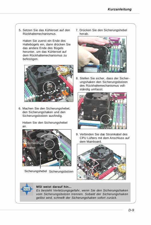
6. Machen Sie den Sicherungshebel,den Sicherungshaken und denSicherungsbolzen ausfindig.
Heben Sie den Sicherungshebelan.
5. Setzen Sie das Kühlerset auf denRückhaltemechanismus.
Haken Sie zuerst ein Ende desHaltebügels ein, dann drücken Siedas andere Ende des Bügelsherunter, um das Kühlerset aufdem Rückhaltemechanismus zubefestigen.
7. Drücken Sie den Sicherungshebelherab.
8. Stellen Sie sicher, dass der Sicher-ungshaken den Sicherungsbolzendes Rückhaltemechanismus voll-ständig umfasst.
Fixed Bolt
9. Verbinden Sie das Stromkabel desCPU Lüfters mit dem Anschluss aufdem Mainboard.Sicherungs-
haken
Sicherungshebel Sicherungsbolzen
MSI weist darauf hin...Es besteht Verletzungsgefahr, wenn Sie den Sicherungshakenvom Sicherungsbolzen trennen. Sobald der Sicherungshakengelöst wird, schnellt der Sicherungshaken sofort zurück.
D-10
MS-7185 ATX Mainboard
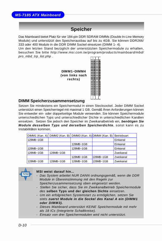
SpeicherDas Mainboard bietet Platz für vier 184-pin DDR SDRAM DIMMs (Double In-Line MemoryModule) und unterstützt den Speicherausbau auf bis zu 4GB. Sie können DDR266/333 oder 400 Module in die DDR DIMM Sockel einsetzen (DIMM 1- 4).Um den letzten Stand bezüglich der unterstützten Speichermodule zu erhalten,besuchen Sie bitte http://www.msi.com.tw/program/products/mainboard/mbd/pro_mbd_trp_list.php .
DIMM SpeicherzusammensetzungSetzen Sie mindestens ein Speichermodul in einen Stecksockel. Jeder DIMM Sockelunterstützt einen Speicherriegel mit maximal 1 GB. Gemäß Ihren Anforderungen könnenSie entweder ein- oder doppelseitige Module verwenden. Sie können Speichermoduleunterschiedlichen Typs und unterschiedlicher Dichte in unterschiedlichen Kanäleneinsetzen. Setzen Sie jedoch den Speicher im Zweikanalbetrieb ein, benötigen SieModule desselben Typs und derselben Speicherdichte, sonst kann es zuInstabilitäten kommen.
DIMM1~DIMM4(von links nach
rechts)
DIMM1 (Kan. A) DIMM2 (Kan. B) DIMM3 (Kan. A) DIMM4 (Kan. B) Betriebsart128MB~1GB Einkanal
128MB~1GB Einkanal128MB~1GB 128MB~1GB Einkanal128MB~1GB 128MB~1GB Zweikanal
128MB~1GB 128MB~1GB Zweikanal128MB~1GB 128MB~1GB 128MB~1GB 128MB~1GB Zweikanal
MSI weist darauf hin...- Das System arbeitet NUR DANN ordnungsgemäß, wenn die DDR
Module in Übereinstimmung mit den Regeln zurSpeicherzusammensetzung oben eingesetzt werden.
- Stellen Sie sicher, dass Sie im Zweikanalbetrieb Speichermoduledes selben Typs und der gleichen Dichte einsetzen.
- Um ein erfolgreichen Systemstart zu ermöglichen, setzen Siestets zuerst Module in die Sockel des Kanal A ein (DIMM1oder DIMM3).
- Dieses Mainboard unterstützt KEINE Speichermodule mit mehrals 18 ICs (Integrierte Schaltkreise).
- Einsatz von drei Speichermodulen wird nicht unterstützt.
D-11
Kurzanleitung
Volt Kerbe
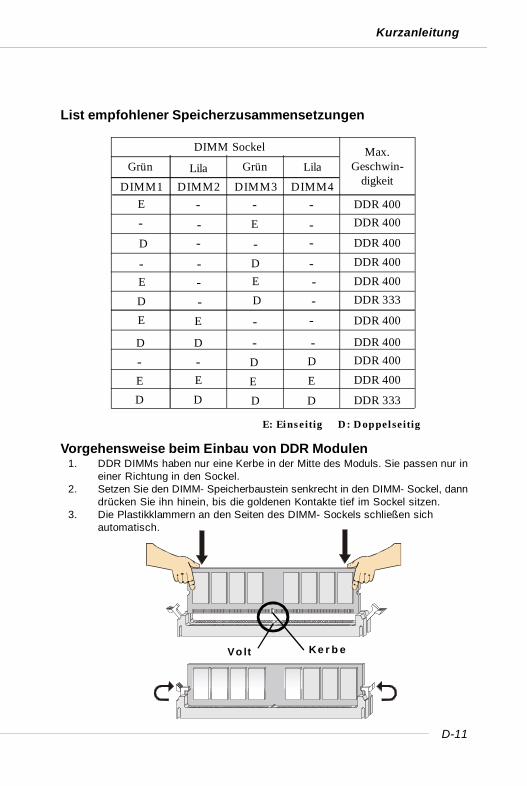
List empfohlener Speicherzusammensetzungen
E: Einseitig D: Doppelseitig
DDR 400DIMM2 DIMM3 DIMM4
E
DIMM Sockel Max.Geschwin-
digkeit
- -E-
D --D-
-E
-
E
DDR 400
DDR 400
DDR 400
DDR 333DDR 400
DDR 400
DDR 400DDR 400
DDR 333
DDR 400
DIMM1-
- --
-
-
EE E E
DD DD
E - E -D - D -
D D - -- - D D
Grün GrünLila Lila
Vorgehensweise beim Einbau von DDR Modulen1. DDR DIMMs haben nur eine Kerbe in der Mitte des Moduls. Sie passen nur in
einer Richtung in den Sockel.2. Setzen Sie den DIMM- Speicherbaustein senkrecht in den DIMM- Sockel, dann
drücken Sie ihn hinein, bis die goldenen Kontakte tief im Sockel sitzen.3. Die Plastikklammern an den Seiten des DIMM- Sockels schließen sich
automatisch.

D-12
MS-7185 ATX Mainboard
Stromversorgung
Das Mainboard unterstützt zur Stromversorgung ATX Netzteile. Bevor Sie denNetzteilstecker einstecken, stellen Sie stets s icher, dass alle Komponentenordnungsgemäß eingebaut sind, um Schäden auszuschließen.
ATX 24-Pin Stromanschluss: ATX1Dient zum Anschluss eines ATX Netzteil. Wenn Sie die Verbindung herstellen, stellenSie sicher, dass der Stecker in der korrekten Ausrichtung eingesteckt wird und diePins ausgerichtet sind. Drücken Sie dann den Netzteilstecker fest in den Steckersockel.
ATX 4-Pin CPU Stromanschluss: JPW1Dieser Anschluss stellt die Versorgung mit 12V für CPUs zur Verfügung.
ATX 4-Pin VGA Stromanschluss: PCIE_PW1Dieser Anschluss wurde entworfen, um PCI Express Grafikkarten mit 12V zuversorgen. W ird dieser Anschluss nicht mit einer angemessenen Stromquelleverbunden, leuchtet die Alarm- LED (LED1).
PIN SIGNAL
13 +3.3V14 -12V15 GND16 PS-ON#17 GND18 GND19 GND20 3VSB21 +5V22 +5V23 +5V24 GND
PIN SIGNAL
1 +3.3V2 +3.3V3 GND4 +5V5 GND6 +5V7 GND8 PWR OK9 5VSB10 +12V11 +12V12 +3.3V
ATX1 Pinbelegung
PIN SIGNAL
1 GND2 GND3 12V4 12V
JPW1 Pinbelegung PCIE_PW1
1234
ATX1
12
1 13
24
JPW1
13 4
2
LED1
PIN SIGNAL
1 5V2 GND3 GND4 +12V
PCIE_PW1 Pinbelegung
MSI weist darauf hin...1. Stellen Sie die Verbindung aller drei Anschlüsse mit einem
angemessenem ATX Netzteil sicher, um den stabilen Betrieb desMainboards sicher zu stellen.
2. Netzteile mit 450 Watt (und mehr) werden aus Gründen derSystemstabilität dringend empfohlen.
3. Die ATX 12V Stromversorgung sollte mit mehr als 20 A erfolgen.
D-13
Kurzanleitung
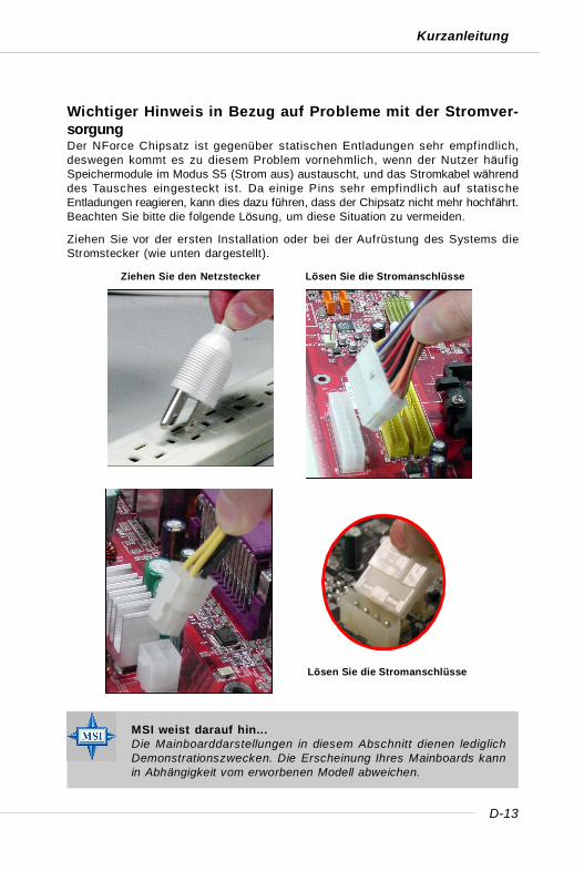
Ziehen Sie den Netzstecker Lösen Sie die Stromanschlüsse
Lösen Sie die Stromanschlüsse
MSI weist darauf hin...Die Mainboarddarstellungen in diesem Abschnitt dienen lediglichDemonstrationszwecken. Die Erscheinung Ihres Mainboards kannin Abhängigkeit vom erworbenen Modell abweichen.
Wichtiger Hinweis in Bezug auf Probleme mit der Stromver-sorgungDer NForce Chipsatz ist gegenüber statischen Entladungen sehr empfindlich,deswegen kommt es zu diesem Problem vornehmlich, wenn der Nutzer häufigSpeichermodule im Modus S5 (Strom aus) austauscht, und das Stromkabel währenddes Tausches eingesteckt is t. Da einige Pins sehr empfindlich auf statischeEntladungen reagieren, kann dies dazu führen, dass der Chipsatz nicht mehr hochfährt.Beachten Sie bitte die folgende Lösung, um diese Situation zu vermeiden.
Ziehen Sie vor der ersten Installation oder bei der Aufrüstung des Systems dieStromstecker (wie unten dargestellt).
D-14
MS-7185 ATX Mainboard
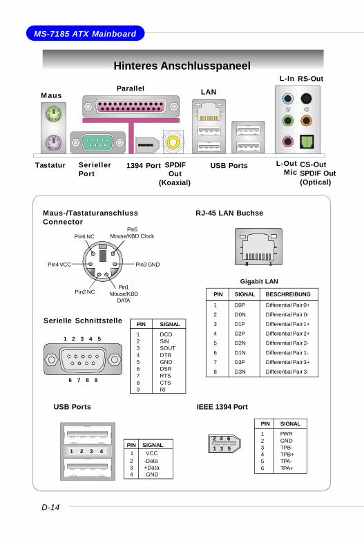
Hinteres Anschlusspaneel
RJ-45 LAN Buchse
8 1
Gigabit LAN
PIN SIGNAL BESCHREIBUNG
1 D0P Differential Pair 0+
2 D0N Differential Pair 0-
3 D1P Differential Pair 1+
4 D2P Differential Pair 2+
5 D2N Differential Pair 2-
6 D1N Differential Pair 1-
7 D3P Differential Pair 3+
8 D3N Differential Pair 3-
Serielle Schnittstelle PIN SIGNAL
1 DCD2 SIN3 SOUT4 DTR5 GND6 DSR7 RTS8 CTS9 RI
1 2 3 4 5
6 7 8 9
USB Ports
1 2 3 4PIN SIGNAL 1 VCC 2 -Data 3 +Data 4 GND
Maus-/TastaturanschlussConnector
Pin1Mouse/KBD
DATAPin2 NC
Pin3 GNDPin4 VCC
Pin5Mouse/KBD ClockPin6 NC
Tastatur SeriellerPort
USB Ports L-OutMic
L-In
MausParallel LAN
1394 Port SPDIFOut
(Koaxial)
RS-Out
CS-OutSPDIF Out(Optical)
IEEE 1394 Port
PIN SIGNAL
1 PWR2 GND3 TPB-4 TPB+5 TPA-6 TPA+
2 4 6
1 3 5
D-15
Kurzanleitung
Anschlüsse
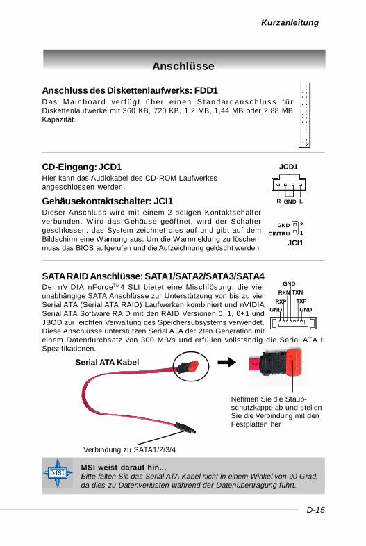
Anschluss des Diskettenlaufwerks: FDD1D as Mai n b oar d ver f üg t üb er e i n en S t an d ar d an s c h l u s s f ü rDiskettenlaufwerke mit 360 KB, 720 KB, 1,2 MB, 1,44 MB oder 2,88 MBKapazität.
CD-Eingang: JCD1Hier kann das Audiokabel des CD-ROM Laufwerkesangeschlossen werden.
JCD1
GNDR L
GNDTXP
TXNGND
RXNRXP
GND
Verbindung zu SATA1/2/3/4
Nehmen Sie die Staub-schutzkappe ab und stellenSie die Verbindung mit denFestplatten her
Serial ATA Kabel
Gehäusekontaktschalter: JCI1Dieser Anschluss wird mit einem 2-poligen Kontaktschalterverbunden. W ird das Gehäuse geöf fnet, wird der Schaltergeschlossen, das System zeichnet dies auf und gibt auf demBildschirm eine Warnung aus. Um die Warnmeldung zu löschen,muss das BIOS aufgerufen und die Aufzeichnung gelöscht werden.
JCI1
21
GNDCINTRU
MSI weist darauf hin...Bitte falten Sie das Serial ATA Kabel nicht in einem Winkel von 90 Grad,da dies zu Datenverlusten während der Datenübertragung führt.
SATA RAID Anschlüsse: SATA1/SATA2/SATA3/SATA4Der nVIDIA nForceTM4 SLI bietet eine Mischlösung, die vierunabhängige SATA Anschlüsse zur Unterstützung von bis zu vierSerial ATA (Serial ATA RAID) Laufwerken kombiniert und nVIDIASerial ATA Software RAID mit den RAID Versionen 0, 1, 0+1 undJBOD zur leichten Verwaltung des Speichersubsystems verwendet.Diese Anschlüsse unterstützen Serial ATA der 2ten Generation miteinem Datendurchsatz von 300 MB/s und erfüllen vollständig die Serial ATA IISpezif ikationen.
D-16
MS-7185 ATX Mainboard
IDE1 (Primärer IDE Anschluss)Die erste Festplatte sollte immer an IDE1 angeschlossen werden. IDE1 kann ein Master-und ein Slave- Laufwerk verwalten. Das zweite Laufwerk muss durch dasentsprechende Setzen einer Steckbrücke als Slave eingestellt werden.IDE2 (Sekundärer IDE Anschluss)An IDE2 kann ebenfalls ein Master und ein Slave- Laufwerk angeschlossen werden.
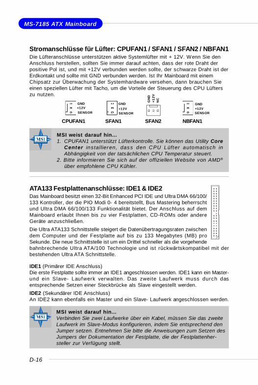
ATA133 Festplattenanschlüsse: IDE1 & IDE2Das Mainboard besitzt einen 32-Bit Enhanced PCI IDE und Ultra DMA 66/100/133 Kontroller, der die PIO Modi 0- 4 bereitstellt, Bus Mastering beherrschtund Ultra DMA 66/100/133 Funktionalität bietet. Der Anschluss auf demMainboard erlaubt Ihnen bis zu vier Festplatten, CD-ROMs oder andereGeräte anzuschließen.Die Ultra ATA133 Schnittstelle steigert die Datenübertragungsraten zwischendem Computer und der Festplatte auf bis zu 133 Megabytes (MB) proSekunde. Die neue Schnittstelle ist um ein Drittel schneller als die vorgehendebahnbrechende Ultra ATA/100 Technologie und ist rückwärtskompatibel mit derbestehenden Ultra ATA Schnittstelle.
NBFAN1
+12VGND
SENSOR
CPUFAN1
SENSOR+12VGND
SFAN1
+12VGND
SENSOR
SFAN2
+12V
GN
D
NC
Stromanschlüsse für Lüfter: CPUFAN1 / SFAN1 / SFAN2 / NBFAN1Die Lüfteranschlüsse unterstützen aktive Systemlüfter mit + 12V. Wenn Sie denAnschluss herstellen, sollten Sie immer darauf achten, dass der rote Draht derpositive Pol ist, und mit +12V verbunden werden sollte, der schwarze Draht ist derErdkontakt und sollte mit GND verbunden werden. Ist Ihr Mainboard mit einemChipsatz zur Überwachung der Systemhardware versehen, dann brauchen Sieeinen speziellen Lüfter mit Tacho, um die Vorteile der Steuerung des CPU Lüfterszu nutzen.
MSI weist darauf hin...Verbinden Sie zwei Laufwerke über ein Kabel, müssen Sie das zweiteLaufwerk im Slave-Modus konfigurieren, indem Sie entsprechend denJumper setzen. Entnehmen Sie bitte die Anweisungen zum Setzen desJumpers der Dokumentation der Festplatte, die der Festplattenher-steller zur Verfügung stellt.
MSI weist darauf hin...1. CPUFAN1 unterstützt Lüfterkontrolle. Sie können das Utility Core
Center installieren, dass den CPU Lüf ter automatisch inAbhängigkeit von der tatsächlichen CPU Temperatur steuert.
2. Bitte informieren Sie sich auf der offiziellen Website von AMD®
über empfohlene CPU Kühler.
D-17
Kurzanleitung
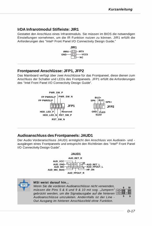
Frontpaneel Anschlüsse: JFP1, JFP2Das Mainboard verfügt über zwei Anschlüsse für das Frontpaneel, diese dienen zumAnschluss der Schalter und LEDs des Frontpaneels. JFP1 erfüllt die Anforderungendes “Intel Front Panel I/O Connectivity Design Guide“.
Audioanschluss des Frontpaneels: JAUD1Der Audio Vorderanschluss JAUD1 ermöglicht den Anschluss von Audioein- und -ausgängen eines Frontpaneels und entspricht den Richtlinien des “Intel® Front PanelI/O Connectivity Design Guide”.
JAUD1
1
2
9
10AUD_MIC
AUD_GND
AUD_MIC_BIAS
AUD_VCC
AUD_FPOUT_R
AUD_RET_R
HP_ONAUD_FPOUT_LAUD_RET_L
IrDA Infrarotmodul Stifleiste: JIR1Gestattet den Anschluss eines Infrarotmoduls. Sie müssen im BIOS die notwendigenEinstellungen vornehmen, um die IR Funktion nutzen zu können. JIR1 erfüllt dieAnforderungen des “Intel® Front Panel I/O Connectivity Design Guide.”
JFP1
HDD_LED_PHDD_LED_N
RST_SW_N
RST_SW_PReserved
FP PWR/SLPFP PWR/SLP
PWR_SW_P
PWR_SW_N
GND
JFP2
SLEDPLED
SPK-BUZ+
BUZ-SPK+
JIR1IRTXIRRX
VCC5NC
GND
MSI weist darauf hin...Wenn Sie die vorderen Audioanschlüsse nicht verwenden,müssen die Pins 5 & 6 und 9 & 10 mit sog. „Jumpern”gebrückt werden, um die Signalausgabe auf die hinterenAudioanschlüsse umzuleiten. Andernfalls ist der Line -Out Ausgang im hinteren Anschlussfeld ohne Funktion.
5
6 10
9
D-18
MS-7185 ATX Mainboard
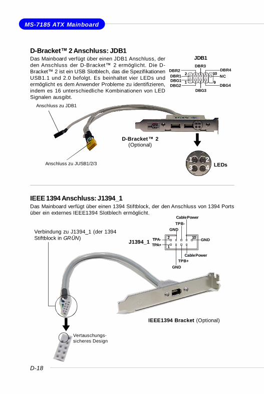
D-Bracket™ 2 Anschluss: JDB1Das Mainboard verfügt über einen JDB1 Anschluss, derden Anschluss der D-Bracket™ 2 ermöglicht. Die D-Bracket™ 2 ist ein USB Slotblech, das die SpezifikationenUSB1.1 und 2.0 befolgt. Es beinhaltet vier LEDs undermöglicht es dem Anwender Probleme zu identifizieren,indem es 16 unterschiedliche Kombinationen von LEDSignalen ausgibt.
IEEE 1394 Anschluss: J1394_1Das Mainboard verfügt über einen 1394 Stiftblock, der den Anschluss von 1394 Portsüber ein externes IEEE1394 Slotblech ermöglicht.
D-Bracket™ 2(Optional)
Anschluss zu JDB1
LEDsAnschluss zu JUSB1/2/31 23 4
Vertauschungs-sicheres Design
Verbindung zu J1394_1 (der 1394Stiftblock in GRÜN)
IEEE1394 Bracket (Optional)
JDB1
1
2
9
10
DBG1DBR1
DBG2
DBR2
DBG3
DBR3
DBG4
DBR4NC
J1394_11
2 10
TPA+TPA-
GND
GND
TPB+
TPB-
Cable Power
GND
Cable Power
D-19
Kurzanleitung
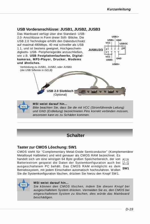
USB Vorderanschlüsse: JUSB1, JUSB2, JUSB3Das Mainboard verfügt über drei Standard- USB-2.0- Anschlüsse in Form dreier Stift- Blöcke. DieUSB 2.0 Technologie erhöht den Datendurchsatzauf maximal 480Mbps, 40 mal schneller als USB1.1, und ist bestens geeignet, Hochgeschwin-digkeits- USB- Peripheriegeräte anzuschließen,wie z.B. USB Festplattenlaufwerke, Digital-kameras, MP3-Player, Drucker, Modemsund ähnliches.
MSI weist darauf hin...Bitte beachten Sie, dass Sie die mit VCC (Stromführende Leitung)und GND (Erdleitung) bezeichneten Pins korrekt verbinden müssen,ansonsten kann es zu Schäden kommen.
Taster zur CMOS Löschung: SW1CMOS steht für “Complementary Metal-Oxide Semiconductor” (KomplementärerMetalloxyd Halbleiter) und wird genauer als CMOS RAM bezeichnet. Eshandelt sich um eine winzigen 64 Byte großen Speicherbereich, der vonBatteriestrom gespeist die Daten der Systemkonf iguration auch beiausgeschaltetem PC behäl t . Das CMOS RAM ermöglicht es demBetriebssystem, mit jedem Einschalten automatisch hochzufahren. WollenSie die Systemkonfiguration löschen, drücken Sie hierzu den Knopf SW1.
Schalter
MSI weist darauf hin...Sie können den CMOS löschen, indem Sie diesen Knopf beiausgeschaltetem System drücken. Vermeiden Sie es, den CMOS beieingeschaltetem System zu löschen, dies würde das Mainboardbeschädigen.
JUSB1/2/3
VCCUSB0-
USB0+
GND
VCCUSB1-
USB1+GND
USBOC
1 2 10
Verbindung zu JUSB1, JUSB2, oder JUSB3(die USB Sifleiste in GELB)
USB 2.0 Slotblech(Optional)
SW1
D-20
MS-7185 ATX Mainboard
Sockel
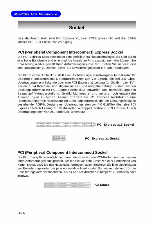
Das Mainboard stellt zwei PCI Express x1, zwei PCI Express x16 und drei 32-bitMaster PCI- Bus Sockel zur Verfügung.
PCI (Peripheral Component Interconnect) Express SockelDie PCI Express Slots verwenden eine serielle Anschlusstechnologie, die sich durcheine hohe Bandbreite und eine niedrige Anzahl an Pins auszeichnet. Hier können SieErweiterungskarten gemäß Ihren Anforderungen einsetzen. Stellen Sie sicher zuerstden Netzstecker zu ziehen, bevor Sie Erweiterungskarten ein- oder ausbauen.
Die PCI Express Architektur stellt eine Hochleistungs- Ein-/Ausgabe- Infrastruktur fürDesktop Plattformen mit Datendurchsätzen zur Verfügung, die bei 2,5 Giga-Übertragungen pro Sekunde über eine PCI Express x1 Leitung für Gigabit- Lan, TV -Karten, 1394 Kontroller und allgemeine Ein- und Ausgabe anfängt. Zudem werdenDesktopplattformen mit PCI Express Architektur entworfen, um Höchstleistungen inBezug auf Videodarstellung, Grafik, Multimedia- und weitere hoch entwickelteAnwendungen zu bieten. Ferner offer iert die PCI Express Architektur eineHochleistungsgrafikinfrastruktur für Desktopplattformen, die die Leistungsfähigkeitbestehender AGP8x Designs mit Übertragungsraten von 4.0 Gbit/Sek über eine PCIExpress 16-fach Leitung für Grafikkarten verdoppelt, während PCI Express 1-fachÜbertragungsraten von 250 MBit/Sek unterstützt.
PCI (Peripheral Component Interconnect) SockelDie PCI Steckplätze ermöglichen Ihnen den Einsatz von PCI-Karten, um das SystemIhren Anforderungen anzupassen. Stellen Sie vor dem Einsetzen oder Entnehmen vonKarten sicher, dass Sie den Netzstecker gezogen haben. Studieren Sie bitte die Anleitungzur Erweiterungskarte, um jede notwendige Hard - oder Softwareeinstellung für dieErweiterungskarte vorzunehmen, sei es an Steckbrücken (“Jumpern”), Schaltern oderim BIOS.
PCI Express x1 Sockel
PCI Express x16 Sockel
PCI Sockel
D-21
Kurzanleitung
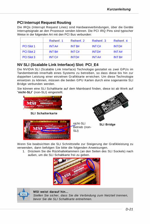
PCI Interrupt Request RoutingDie IRQs (Interrupt Request Lines) sind Hardwareverbindungen, über die GeräteInterruptsignale an den Prozessor senden können. Die PCI IRQ Pins sind typischerWeise in der folgenden Art mit den PCI Bus verbunden:
NV SLI (Scalable Link Interface) Slot: PCI_E4Die NVIDIA SLI (Scalable Link Interface) Technologie gestattet es zwei GPUs imTandembetrieb innerhalb eines Systems zu betreiben, so dass diese bis hin zurdoppelten Leistung einer einzelnen Grafikkarte erreichen. Um diese Technologieeinsetzen zu können, müssen die beiden GPU Karten durch eine sogenannte SLIBridge verbunden werden.Sie können eine SLI Schaltkarte auf dem Mainboard f inden, diese ist ab Werk auf“nicht-SLI” (non-SLI) eingestellt.
MSI weist darauf hin...Stellen Sie sicher, dass Sie die Verbindung zum Netzteil trennen,bevor Sie die SLI Schaltkarte entnehmen.
Wenn Sie beabsichten die SLI Schnittstelle zur Steigerung der Grafikleistung zuverwenden, dann befolgen Sie bitte die folgenden Anweisungen.
1. Drückem Sie die Rückhalteklammern (an den Seiten des SLI Sockels) nachaußen, um die SLI Schaltkarte frei zu geben.
SLI Bridge
Reihenf. 1 Reihenf. 2 Reihenf. 3 Reihenf. 4
PCI Slot 1 INT A# INT B# INT C# INT D#
PCI Slot 2 INT B# INT C# INT D# INT A#
PCI Slot 3 INT C# INT D# INT A# INT B#
SLI Schalterkarte
nicht-SLIBetrieb (non-SLI)
D-22
MS-7185 ATX Mainboard
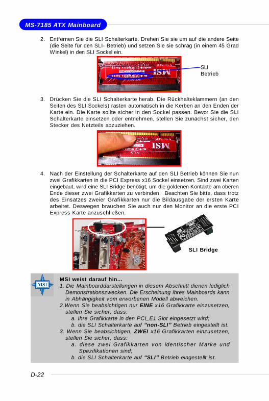
2. Entfernen Sie die SLI Schalterkarte. Drehen Sie sie um auf die andere Seite(die Seite für den SLI- Betrieb) und setzen Sie sie schräg (in einem 45 GradWinkel) in den SLI Sockel ein.
3. Drücken Sie die SLI Schalterkarte herab. Die Rückhalteklammern (an denSeiten des SLI Sockels) rasten automatisch in die Kerben an den Enden derKarte ein. Die Karte sollte sicher in den Sockel passen. Bevor Sie die SLISchalterkarte einsetzen oder entnehmen, stellen Sie zunächst sicher, denStecker des Netzteils abzuziehen.
MSI weist darauf hin...1. Die Mainboarddarstellungen in diesem Abschnitt dienen lediglich
Demonstrationszwecken. Die Erscheinung Ihres Mainboards kannin Abhängigkeit vom erworbenen Modell abweichen.
2.Wenn Sie beabsichtigen nur EINE x16 Grafikkarte einzusetzen,stellen Sie sicher, dass:
a. Ihre Grafikkarte in den PCI_E1 Slot eingesetzt wird;b. die SLI Schalterkarte auf “non-SLI” Betrieb eingestellt ist.
3. Wenn Sie beabsichtigen, ZWEI x16 Grafikkarten einzusetzen,stellen Sie sicher, dass:
a. diese zwei Graf ikkarten von identischer Marke undSpezifikationen sind;
b. die SLI Schalterkarte auf “SLI” Betrieb eingestellt ist.
SLI Bridge
4. Nach der Einstellung der Schalterkarte auf den SLI Betrieb können Sie nunzwei Grafikkarten in die PCI Express x16 Sockel einsetzen. Sind zwei Karteneingebaut, wird eine SLI Bridge benötigt, um die goldenen Kontakte am oberenEnde dieser zwei Grafikkarten zu verbinden. Beachten Sie bitte, dass trotzdes Einsatzes zweier Grafikkarten nur die Bildausgabe der ersten Kartearbeitet. Deswegen brauchen Sie auch nur den Monitor an die erste PCIExpress Karte anzuschließen.
SLIBetrieb
D-23
Kurzanleitung
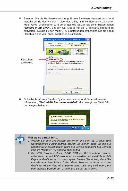
5. Beenden Sie die Hardwareeinrichtung, führen Sie einen Neustart durch undinstallieren Sie den NV SLI Treiber/das Utility. Ein Konfigurationspaneel fürMulti- GPU Grafikkarten wird bereit gestellt. Setzen Sie einen Haken neben“Enable multi-GPU”, um den SLI Modus für die Grafikkarte onboard zuaktivieren. (Details zu den Multi-GPU Einstellungen entnehmen Sie bitte demHandbuch der von Ihnen eworbenen Grafikkarte).
6. Schließlich müssen Sie das System neu starten und Sie erhalten eineInformation, “Multi-GPU has been enabled“, die besagt das Multi GPUnun eingeschaltet ist.
MSI weist darauf hin...1. Wollen Sie eine Grafikkarte entfernen und vom SLI-Modus zum
Normalbetrieb zurückkehren, stellen Sie sicher, dass Sie die SLISchalterkarte zurücksetzen (vom SLI Betrieb zum nicht-SLI Betrieb)und die “MultiGPU” Funktion abschalten.
2. Der VGA Stromanschluss PCIE_PW1 (S. D-12) onboard wurdeentworfen, um mit 12V verbunden zu werden und zusätzliche PCIExpress Grafikkarten zu versorgen. Stellen Sie sicher, dass Siemit diesem Anschluss (oder dem Stromanschluss auf derGrafikkarte) ein Netzteil angemessener Leistung verbinden, umden stabilen Betrieb der Grafikkarte sicher zu stellen.
Kästchenanklicken.
D-24
MS-7185 ATX Mainboard
BIOS Setup
MSI weist darauf hin...Die Menüpunkte jeder BIOS Kategorie, die in diesem Kapitelbeschrieben wird, werden permanent auf den neuesten Standgebracht, um die Systemleistung zu verbessern. Aus diesem Grundekann die Beschreibung geringfügig von der aktuellsten Version desBIOS abweichen und sollte dementsprechend led ig lich a lsAnhaltspunkt dienen.
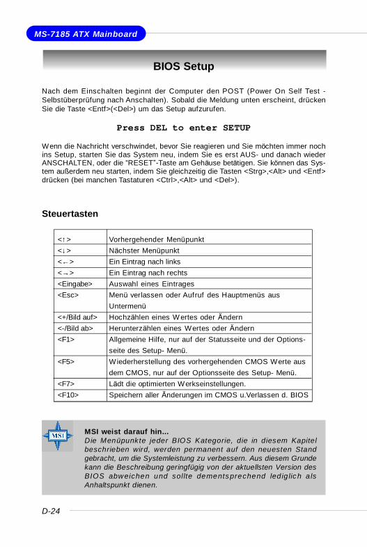
Nach dem Einschalten beginnt der Computer den POST (Power On Self Test -Selbstüberprüfung nach Anschalten). Sobald die Meldung unten erscheint, drückenSie die Taste <Entf>(<Del>) um das Setup aufzurufen.
Press DEL to enter SETUPWenn die Nachricht verschwindet, bevor Sie reagieren und Sie möchten immer nochins Setup, starten Sie das System neu, indem Sie es erst AUS- und danach wiederANSCHALTEN, oder die “RESET”-Taste am Gehäuse betätigen. Sie können das Sys-tem außerdem neu starten, indem Sie gleichzeitig die Tasten <Strg>,<Alt> und <Entf>drücken (bei manchen Tastaturen <Ctrl>,<Alt> und <Del>).
Steuertasten
<↑> Vorhergehender Menüpunkt<↓> Nächster Menüpunkt<←> Ein Eintrag nach links<→> Ein Eintrag nach rechts<Eingabe> Auswahl eines Eintrages<Esc> Menü verlassen oder Aufruf des Hauptmenüs aus
Untermenü<+/Bild auf> Hochzählen eines W ertes oder Ändern<-/Bild ab> Herunterzählen eines Wertes oder Ändern<F1> Allgemeine Hilfe, nur auf der Statusseite und der Options-
seite des Setup- Menü.<F5> Wiederherstellung des vorhergehenden CMOS Werte aus
dem CMOS, nur auf der Optionsseite des Setup- Menü.<F7> Lädt die optimierten Werkseinstellungen.<F10> Speichern aller Änderungen im CMOS u.Verlassen d. BIOS
D-25
Kurzanleitung
Das Hauptmenü
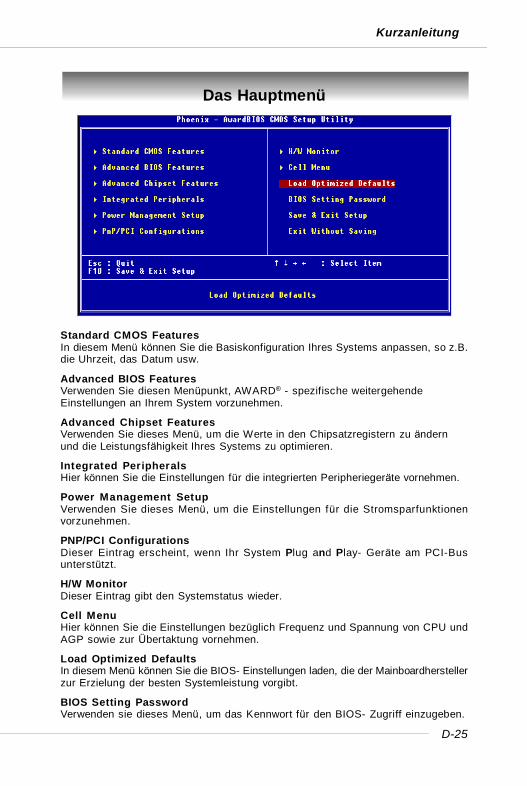
Standard CMOS FeaturesIn diesem Menü können Sie die Basiskonfiguration Ihres Systems anpassen, so z.B.die Uhrzeit, das Datum usw.
Advanced BIOS FeaturesVerwenden Sie diesen Menüpunkt, AWARD® - spezifische weitergehendeEinstellungen an Ihrem System vorzunehmen.
Advanced Chipset FeaturesVerwenden Sie dieses Menü, um die Werte in den Chipsatzregistern zu ändernund die Leistungsfähigkeit Ihres Systems zu optimieren.
Integrated PeripheralsHier können Sie die Einstellungen für die integrierten Peripheriegeräte vornehmen.
Power Management SetupVerwenden Sie dieses Menü, um die Einstellungen für die Stromsparfunktionenvorzunehmen.
PNP/PCI ConfigurationsDieser Eintrag erscheint, wenn Ihr System Plug and Play- Geräte am PCI-Busunterstützt.
H/W MonitorDieser Eintrag gibt den Systemstatus wieder.
Cell MenuHier können Sie die Einstellungen bezüglich Frequenz und Spannung von CPU undAGP sowie zur Übertaktung vornehmen.
Load Optimized DefaultsIn diesem Menü können Sie die BIOS- Einstellungen laden, die der Mainboardherstellerzur Erzielung der besten Systemleistung vorgibt.
BIOS Setting PasswordVerwenden sie dieses Menü, um das Kennwort für den BIOS- Zugriff einzugeben.
D-26
MS-7185 ATX Mainboard
Cell Menu
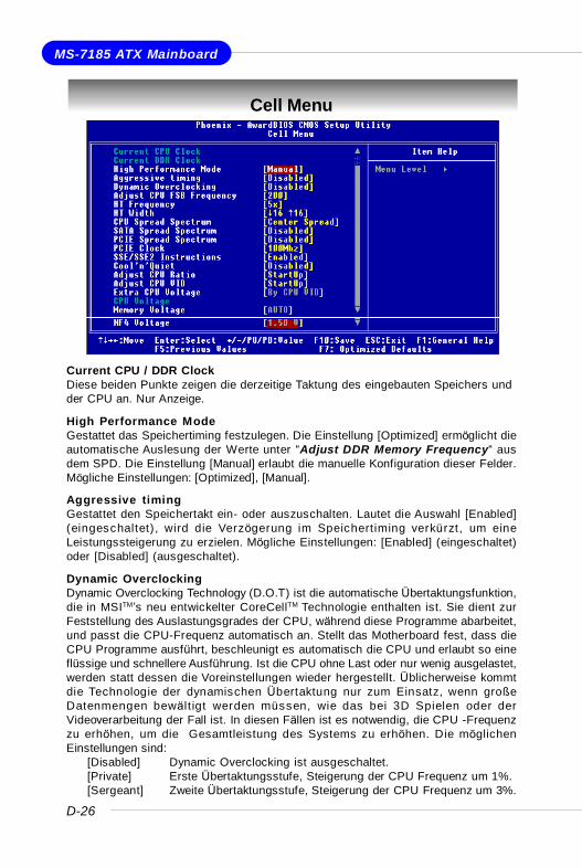
Current CPU / DDR ClockDiese beiden Punkte zeigen die derzeitige Taktung des eingebauten Speichers undder CPU an. Nur Anzeige.
High Performance ModeGestattet das Speichertiming festzulegen. Die Einstellung [Optimized] ermöglicht dieautomatische Auslesung der Werte unter “Adjust DDR Memory Frequency“ ausdem SPD. Die Einstellung [Manual] erlaubt die manuelle Konfiguration dieser Felder.Mögliche Einstellungen: [Optimized], [Manual].
Aggressive timingGestattet den Speichertakt ein- oder auszuschalten. Lautet die Auswahl [Enabled](eingeschaltet), wird die Verzögerung im Speichertiming verkürzt, um eineLeistungssteigerung zu erzielen. Mögliche Einstellungen: [Enabled] (eingeschaltet)oder [Disabled] (ausgeschaltet).
Dynamic OverclockingDynamic Overclocking Technology (D.O.T) ist die automatische Übertaktungsfunktion,die in MSITM’s neu entwickelter CoreCellTM Technologie enthalten ist. Sie dient zurFeststellung des Auslastungsgrades der CPU, während diese Programme abarbeitet,und passt die CPU-Frequenz automatisch an. Stellt das Motherboard fest, dass dieCPU Programme ausführt, beschleunigt es automatisch die CPU und erlaubt so eineflüssige und schnellere Ausführung. Ist die CPU ohne Last oder nur wenig ausgelastet,werden statt dessen die Voreinstellungen wieder hergestellt. Üblicherweise kommtdie Technologie der dynamischen Übertaktung nur zum Einsatz, wenn großeDatenmengen bewäl t igt werden müssen, wie das bei 3D Spielen oder derVideoverarbeitung der Fall ist. In diesen Fällen ist es notwendig, die CPU -Frequenzzu erhöhen, um die Gesamtleistung des Systems zu erhöhen. Die möglichenEinstellungen sind:
[Disabled] Dynamic Overclocking ist ausgeschaltet.[Private] Erste Übertaktungsstufe, Steigerung der CPU Frequenz um 1%.[Sergeant] Zweite Übertaktungsstufe, Steigerung der CPU Frequenz um 3%.
D-27
Kurzanleitung
[Captain] Dritte Übertaktungsstufe, Steigerung der CPU Frequenz um 5%.[Colonel] Vierte Übertaktungsstufe, Steigerung der CPU Frequenz um 7%.[General] Fünfte Übertaktungsstufe, Steigerung der CPU Frequenz um 9%.[Commander] Sechste Übertaktungsstufe, Steigerung der CPU Frequenz um
11%.
Adjust CPU FSB FrequencyGestattet die Wahl der Taktfrequenz des CPU Front Side Bus (in MHz). Wählen Siedie benötigte Frequenz mit einer Zahl zwischen [200] und [400].
HT FrequencySetzt die maximale Betriebsfrequenz des Taktgebers des Hypertransport Links fest.
HT WidthDies dient zur Einstellung der HT Bandbreite zwischen CPU & Chip.Die Markierung “↑“bedeuted Bandbreite vom Chip zur CPU. Ein ↓ bedeutet HT Bandbreite von der CPUzum Chip HT. Mögliche Einstellungen: [ ↓ 8 ↑ 8], [ ↓ 16 ↑ 8], [↓ 8 ↑16], [ ↓16 ↑16].
CPU Spread SpectrumDient zum Ein- oder Ausschalten der CPU Spread Spectrum Funktion. Setzen Siediese Einstellung stets [Disabled] (ausgeschaltet), wenn Sie die CPU übertakten.Mögliche Einstellungen: [Center Spread], [Disabled] (ausgeschaltet).
SATA Spread SpectrumDient zum Ein- oder Ausschalten der SATA Spread Spectrum Funktion. Setzen Siediese Einstellung stets auf[Disabled] (ausgeschaltet), wenn Sie die CPU übertakten.Mögliche Einstellungen: [Disabled] (ausgeschaltet), [Down Spread].
PCIE Spread SpectrumDient zum Ein- oder Ausschalten der PCIE Spread Spectrum Funktion. Setzen Siediese Einstellung stets [Disabled] (ausgeschaltet), wenn Sie die CPU übertakten.Mögliche Einstellungen: [Disabled] (ausgeschaltet), [Down Spread].
PCIE ClockGestattet es, die Taktfrequenz (in Mhz) des PCIE Bus zu wählen. Wählen Sie diebenötigte Frequenz als Zahl zwischen [100] und [145].
SSE/ SSE2 InstructionsDiese Einstellung schaltet die SSE/SSE2 Instructions ein-/aus. Die Streaming SIMDExtensions (SSE) wurden mit dem Pentium III Prozessor eingeführt. Die SSEErweiterungen bestehen aus einem neuen Satz von Befehlen und einen neuen Satzvon Registern. Diese Befehle und Register wurden entworfen, um Single-InstructionMultiple-Data (SIMD) Berechnungen mit einfach präzisen Fließkommazahlendurchzuführen.
MSI weist darauf hin...Obgleich die Dynamic Overc locking Technology stabiler is t alsmanuelles Übertakten, ist es dennoch grundsätzlich riskant. Es istempfehlenswert zuerst sicher zu stellen, dass Ihre CPU eineregelmäßige Übertaktung verträgt. Sollten Sie feststellen, dass IhrPC instabil erscheint oder ohne erkennbaren Grund Neustartsdurchführt, it es besser, die dynamische Übertaktung abzuschaltenoder aber eine niedrigere Übertaktungsstufe zu wählen. Im Übrigenist zu erwähnen, dass Sie das Dynamic Overclocking zuerstabschalten müssen, bevor Sie Ihr System manuell übertakten.
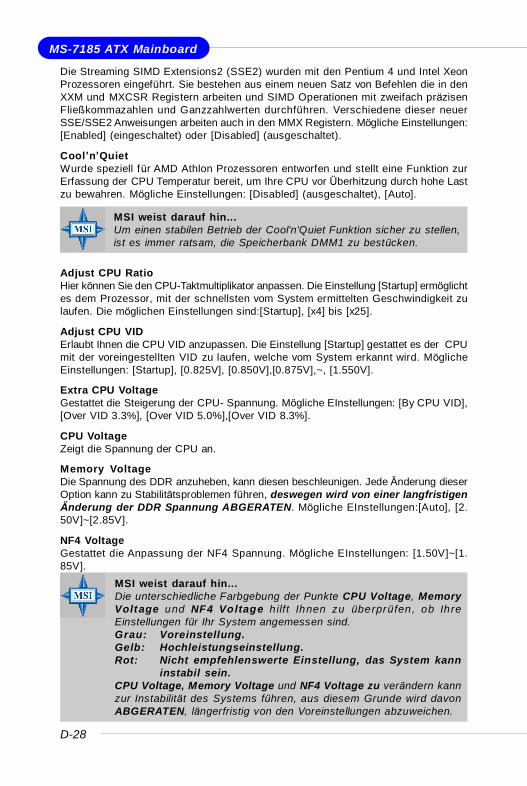
D-28
MS-7185 ATX Mainboard
Die Streaming SIMD Extensions2 (SSE2) wurden mit den Pentium 4 und Intel XeonProzessoren eingeführt. Sie bestehen aus einem neuen Satz von Befehlen die in denXXM und MXCSR Registern arbeiten und SIMD Operationen mit zweifach präzisenFließkommazahlen und Ganzzahlwerten durchführen. Verschiedene dieser neuerSSE/SSE2 Anweisungen arbeiten auch in den MMX Registern. Mögliche Einstellungen:[Enabled] (eingeschaltet) oder [Disabled] (ausgeschaltet).
Cool’n’QuietWurde speziell für AMD Athlon Prozessoren entworfen und stellt eine Funktion zurErfassung der CPU Temperatur bereit, um Ihre CPU vor Überhitzung durch hohe Lastzu bewahren. Mögliche Einstellungen: [Disabled] (ausgeschaltet), [Auto].
Adjust CPU RatioHier können Sie den CPU-Taktmultiplikator anpassen. Die Einstellung [Startup] ermöglichtes dem Prozessor, mit der schnellsten vom System ermittelten Geschwindigkeit zulaufen. Die möglichen Einstellungen sind:[Startup], [x4] bis [x25].
Adjust CPU VIDErlaubt Ihnen die CPU VID anzupassen. Die Einstellung [Startup] gestattet es der CPUmit der voreingestellten VID zu laufen, welche vom System erkannt wird. MöglicheEinstellungen: [Startup], [0.825V], [0.850V],[0.875V],~, [1.550V].
Extra CPU VoltageGestattet die Steigerung der CPU- Spannung. Mögliche EInstellungen: [By CPU VID],[Over VID 3.3%], [Over VID 5.0%],[Over VID 8.3%].
CPU VoltageZeigt die Spannung der CPU an.
Memory VoltageDie Spannung des DDR anzuheben, kann diesen beschleunigen. Jede Änderung dieserOption kann zu Stabilitätsproblemen führen, deswegen wird von einer langfristigenÄnderung der DDR Spannung ABGERATEN. Mögliche EInstellungen:[Auto], [2.50V]~[2.85V].
NF4 VoltageGestattet die Anpassung der NF4 Spannung. Mögliche EInstellungen: [1.50V]~[1.85V].
MSI weist darauf hin...Um einen stabilen Betrieb der Cool'n'Quiet Funktion sicher zu stellen,ist es immer ratsam, die Speicherbank DMM1 zu bestücken.
MSI weist darauf hin...Die unterschiedliche Farbgebung der Punkte CPU Voltage, MemoryVoltage und NF4 Voltage h ilf t Ihnen zu überprü fen, ob IhreEinstellungen für Ihr System angemessen sind.Grau: Voreinstellung.Gelb: Hochleistungseinstellung.Rot: Nicht empfehlenswerte Einstellung, das System kann
instabil sein.CPU Voltage, Memory Voltage und NF4 Voltage zu verändern kannzur Instabilität des Systems führen, aus diesem Grunde wird davonABGERATEN, längerfristig von den Voreinstellungen abzuweichen.

F-1
Guide d’utilisation
K8N SLI Series(MS-7185 v1.X)
Cart Mère ATX
Français

F-2
Carte Mère ATX MS-7185

F-3
Guide d’utilisation
MS-7185 (v1.X)Guide d’utilisation
Félicitation vous venez d’acheter une carte mère ATX K8N SLI Series(MS-7185 v1.X), une excellente carte mère ATX créée par MSI.
Basé sur l’innovant Chipset nVIDIA® nForceTM4 SLI pour une efficacitédu système optimale, la carte mère K8N SLI Series est compatibleavec les derniers processeurs AMD K8 AthlonTM 64 X2 Dual-Core/ AthlonTM 64 FX / AthlonTM 64 (Socket 939) et supporte jusqu’àquatre DDR DIMMs 144 bits (à 200, 266, 333, et 400 MHz) une capacitéde mémoire maximum de 4GB.
MSI Vous Rappelle...1. Merci de noter que le CD MSI Driver/Utility de cette carte
mère est uniquement compatible avec Windows 2000/XPuniquement.
2. Afin de créer un volume RAID bootable pour Windows 2000,Microsoft’s Windows 2000 Service Pack 4 (SP4) est recquis.Si vous bootez sans SP4, un CD d’installation de combinaisondoit être créé avant d’essayer d’installer le système sur levolumle RAID bootable.Afin de créer le CD d’installation de combinaison, merci devous réferez au site suivant :http://www.microsoft.com/windows2000/downloads/servicepacks/sp4/HFdeploy.htm
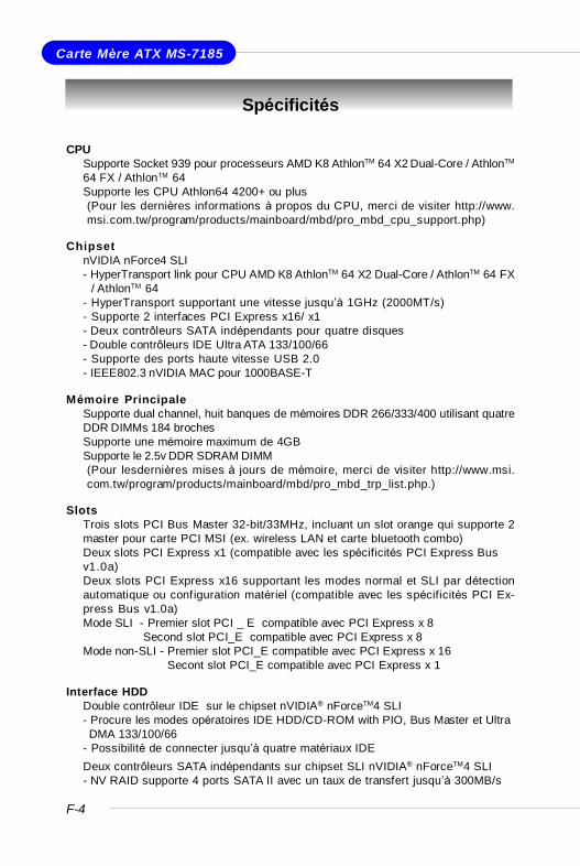
F-4
Carte Mère ATX MS-7185
Spécificités
CPUÜ Supporte Socket 939 pour processeurs AMD K8 AthlonTM 64 X2 Dual-Core / AthlonTM
64 FX / AthlonTM 64Ü Supporte les CPU Athlon64 4200+ ou plus
(Pour les dernières informations à propos du CPU, merci de visiter http://www.msi.com.tw/program/products/mainboard/mbd/pro_mbd_cpu_support.php)
ChipsetÜ nVIDIA nForce4 SLI
- HyperTransport link pour CPU AMD K8 AthlonTM 64 X2 Dual-Core / AthlonTM 64 FX/ AthlonTM 64
- HyperTransport supportant une vitesse jusqu’à 1GHz (2000MT/s)- Supporte 2 interfaces PCI Express x16/ x1- Deux contrôleurs SATA indépendants pour quatre disques- Double contrôleurs IDE Ultra ATA 133/100/66- Supporte des ports haute vitesse USB 2.0- IEEE802.3 nVIDIA MAC pour 1000BASE-T
Mémoire PrincipaleÜ Supporte dual channel, huit banques de mémoires DDR 266/333/400 utilisant quatre
DDR DIMMs 184 brochesÜ Supporte une mémoire maximum de 4GBÜ Supporte le 2.5v DDR SDRAM DIMM
(Pour lesdernières mises à jours de mémoire, merci de visiter http://www.msi.com.tw/program/products/mainboard/mbd/pro_mbd_trp_list.php.)
SlotsÜ Trois slots PCI Bus Master 32-bit/33MHz, incluant un slot orange qui supporte 2
master pour carte PCI MSI (ex. wireless LAN et carte bluetooth combo)Ü Deux slots PCI Express x1 (compatible avec les spécificités PCI Express Bus
v1.0a)Ü Deux slots PCI Express x16 supportant les modes normal et SLI par détection
automatique ou configuration matériel (compatible avec les spécificités PCI Ex-press Bus v1.0a)Mode SLI - Premier slot PCI _ E compatible avec PCI Express x 8
Second slot PCI_E compatible avec PCI Express x 8Mode non-SLI - Premier slot PCI_E compatible avec PCI Express x 16
Secont slot PCI_E compatible avec PCI Express x 1
Interface HDDÜ Double contrôleur IDE sur le chipset nVIDIA® nForceTM4 SLI
- Procure les modes opératoires IDE HDD/CD-ROM with PIO, Bus Master et UltraDMA 133/100/66
- Possibilité de connecter jusqu’à quatre matériaux IDEÜ Deux contrôleurs SATA indépendants sur chipset SLI nVIDIA® nForceTM4 SLI
- NV RAID supporte 4 ports SATA II avec un taux de transfert jusqu’à 300MB/s
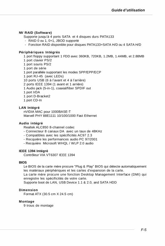
F-5
Guide d’utilisation
NV RAID (Software)Ü Supporte jusqu’à 4 ports SATA et 4 disques durs PATA133
- RAID 0 ou 1, 0+1, JBOD supporté- Fonction RAID disponible pour disques PATA133+SATA H/D ou 4 SATA H/D
Périphériques IntégrésÜ 1 port floppy supportant 1 FDD avec 360KB, 720KB, 1.2MB, 1.44MB, et 2.88MBÜ 1 port clavier PS/2Ü 1 port souris PS/2Ü 1 port de sérieÜ 1 port parallèle supportant les modes SPP/EPP/ECPÜ 1 port RJ-45 (avec LEDs)Ü 10 ports USB (6 à l’avant et 4 à l’arrière)Ü 2 ports IEEE 1394 (1 avant et 1 arrière)Ü 1 Audio jack (5-in-1), coaxial/fiber SPDIF outÜ 1 port IrDAÜ 1 port D-Bracket2Ü 1 port CD-In
LAN IntégréÜ nVIDIA MAC pour 1000BASE-TÜ Marvell PHY 88E1111 10/100/1000 Fast Ethernet
Audio intégréÜ Realtek ALC850 8-channel codec
- Connecteur 8 canaux DA avec un taux de 48KHz- Compatibles avec les spécificités AC97 2.3- Recquière les performances audio PC 97/2001- Recquière Microsoft WHQL / WLP 2.0 audio
IEEE 1394 IntégréÜ Contrôleur VIA VT6307 IEEE 1394
BIOSÜ Le BIOS de la carte mère procure “Plug & Play” BIOS qui détecte automatiquement
les matériaux périphériques et les cartes d’expansion de la carte.Ü La carte mère procure une fonction Desktop Management Interface (DMI) qui
enregistre les spécificités de votre carte.Ü Supporte boot de LAN, USB Device 1.1 & 2.0, and SATA HDD
DimensionÜ Format ATX (30.5 cm X 24.5 cm)
MontageÜ 9 trous de montage

F-6
Carte Mère ATX MS-7185
Guide des Composants
I/O Ports,p. F-14
DDR DIMMs, p. F-10
SFAN2, p. F-16
NBFAN1,p. F-16
CPUFAN1,SFAN1, p. F-12
JIR1, p. F-17
PCIE_PW1,JPW1, p. F-12
SW1, p. F-19
JCI1, p. F-15
JDB1, p. F-18
IDE1/2,p. F-16
JAUD1, p. F-17
FDD1, p. F-15
JUSB1/2/3, p. F-19
PCI ExpressSlots, p. F-20
J1394_1,p. F-18
SATA1/2/3/4, p. F-15
JFP2, p. F-17
JCD1, p. F-15
PCI Slots,p. F-20
JFP1, p. F-17
ATX1, p. F-12
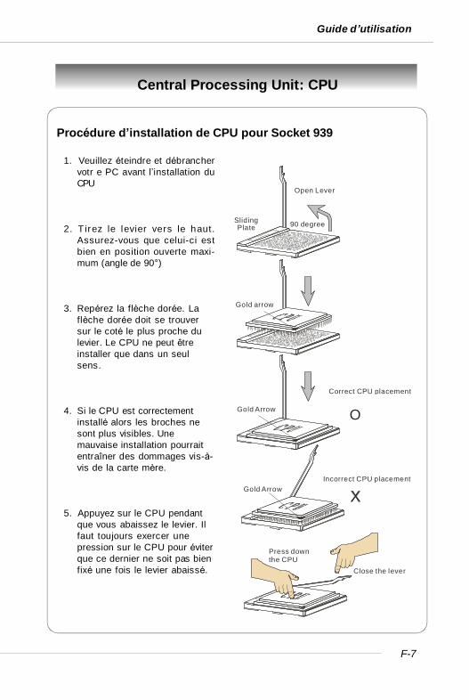
F-7
Guide d’utilisation
Central Processing Unit: CPU
Open Lever
90 degreeSliding Plate
Gold arrow
Gold Arrow
Gold Arrow
Correct CPU placement
O
Incorrect CPU placement
Press down the CPU
Close the lever
Procédure d’installation de CPU pour Socket 939
1. Veuillez éteindre et débranchervotr e PC avant l’installation duCPU
2. T irez le levier vers le haut.Assurez-vous que celui-ci estbien en position ouverte maxi-mum (angle de 90°)
3. Repérez la flèche dorée. Laflèche dorée doit se trouversur le coté le plus proche dulevier. Le CPU ne peut êtreinstaller que dans un seulsens.
4. Si le CPU est correctementinstallé alors les broches nesont plus visibles. Unemauvaise installation pourraitentraîner des dommages vis-à-vis de la carte mère.
5. Appuyez sur le CPU pendantque vous abaissez le levier. Ilfaut toujours exercer unepression sur le CPU pour éviterque ce dernier ne soit pas bienfixé une fois le levier abaissé.
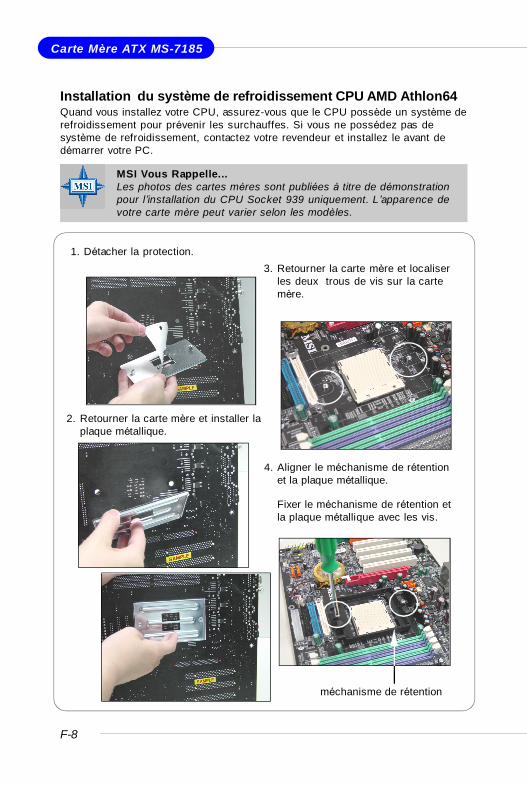
F-8
Carte Mère ATX MS-7185
Installation du système de refroidissement CPU AMD Athlon64Quand vous installez votre CPU, assurez-vous que le CPU possède un système derefroidissement pour prévenir les surchauffes. Si vous ne possédez pas desystème de refroidissement, contactez votre revendeur et installez le avant dedémarrer votre PC.
1. Détacher la protection.
2. Retourner la carte mère et installer laplaque métallique.
3. Retourner la carte mère et localiserles deux trous de vis sur la cartemère.
4. Aligner le méchanisme de rétentionet la plaque métallique.
Fixer le méchanisme de rétention etla plaque métallique avec les vis.
méchanisme de rétention
MSI Vous Rappelle...Les photos des cartes mères sont publiées à titre de démonstrationpour l’installation du CPU Socket 939 uniquement. L’apparence devotre carte mère peut varier selon les modèles.
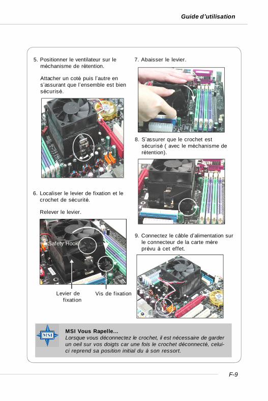
F-9
Guide d’utilisation
6. Localiser le levier de fixation et lecrochet de sécurité.
Relever le levier.
5. Positionner le ventilateur sur leméchanisme de rétention.
Attacher un coté puis l’autre ens’assurant que l’ensemble est biensécurisé.
7. Abaisser le levier.
8. S’assurer que le crochet estsécurisé ( avec le méchanisme derétention).
Safety Hook
Vis de f ixationLevier defixation
9. Connectez le câble d’alimentation surle connecteur de la carte mèreprévu à cet effet.
MSI Vous Rapelle...Lorsque vous déconnectez le crochet, il est nécessaire de garderun oeil sur vos doigts car une fois le crochet déconnecté, celui-ci reprend sa position initial du à son ressort.
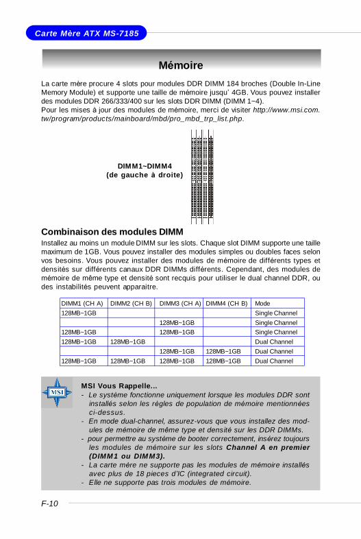
F-10
Carte Mère ATX MS-7185
MémoireLa carte mère procure 4 slots pour modules DDR DIMM 184 broches (Double In-LineMemory Module) et supporte une taille de mémoire jusqu’ 4GB. Vous pouvez installerdes modules DDR 266/333/400 sur les slots DDR DIMM (DIMM 1~4).Pour les mises à jour des modules de mémoire, merci de visiter http://www.msi.com.tw/program/products/mainboard/mbd/pro_mbd_trp_list.php.
Combinaison des modules DIMMInstallez au moins un module DIMM sur les slots. Chaque slot DIMM supporte une taillemaximum de 1GB. Vous pouvez installer des modules simples ou doubles faces selonvos besoins. Vous pouvez installer des modules de mémoire de différents types etdensités sur différents canaux DDR DIMMs différents. Cependant, des modules demémoire de même type et densité sont recquis pour utiliser le dual channel DDR, oudes instabilités peuvent apparaitre.
MSI Vous Rappelle...- Le système fonctionne uniquement lorsque les modules DDR sont
installés selon les règles de population de mémoire mentionnéesci-dessus.
- En mode dual-channel, assurez-vous que vous installez des mod-ules de mémoire de même type et densité sur les DDR DIMMs.
- pour permettre au système de booter correctement, insérez toujoursles modules de mémoire sur les slots Channel A en premier(DIMM1 ou DIMM3).
- La carte mère ne supporte pas les modules de mémoire installésavec plus de 18 pieces d’IC (integrated circuit).
- Elle ne supporte pas trois modules de mémoire.
DIMM1~DIMM4(de gauche à droite)
DIMM1 (CH A) DIMM2 (CH B) DIMM3 (CH A) DIMM4 (CH B) Mode128MB~1GB Single Channel
128MB~1GB Single Channel128MB~1GB 128MB~1GB Single Channel128MB~1GB 128MB~1GB Dual Channel
128MB~1GB 128MB~1GB Dual Channel128MB~1GB 128MB~1GB 128MB~1GB 128MB~1GB Dual Channel
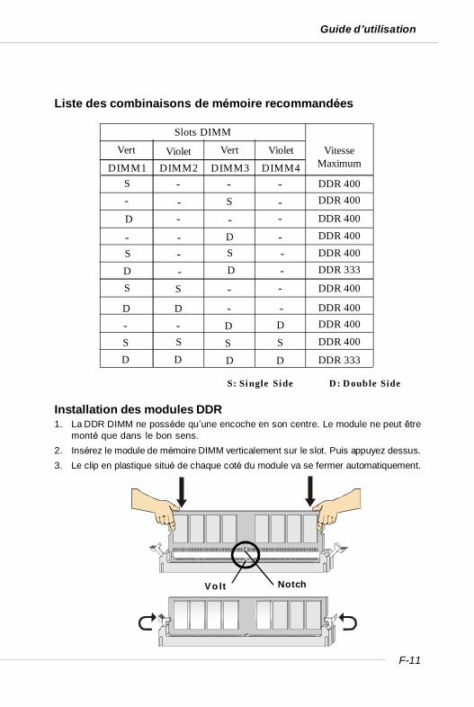
F-11
Guide d’utilisation
Installation des modules DDR1. La DDR DIMM ne posséde qu’une encoche en son centre. Le module ne peut être
monté que dans le bon sens.2. Insérez le module de mémoire DIMM verticalement sur le slot. Puis appuyez dessus.3. Le clip en plastique situé de chaque coté du module va se fermer automatiquement.
Volt Notch
Liste des combinaisons de mémoire recommandées
S: Single Side D: Double Side
DDR 400DIMM2 DIMM3 DIMM4
S
Slots DIMM
VitesseMaximum
- -S-
D --D-
-S
-
S
DDR 400
DDR 400
DDR 400
DDR 333DDR 400
DDR 400
DDR 400DDR 400
DDR 333
DDR 400
DIMM1-
- --
-
-
SS S S
DD DD
S - S -D - D -
D D - -- - D D
Vert VertViolet Violet
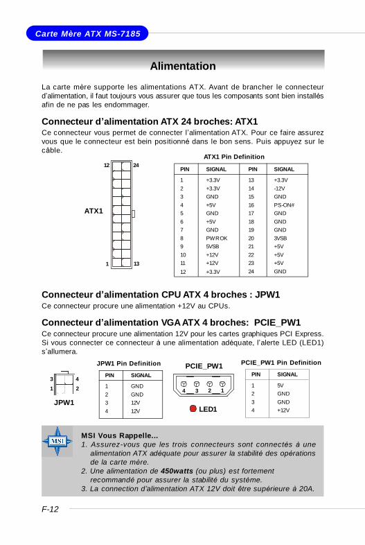
F-12
Carte Mère ATX MS-7185
Alimentation
La carte mère supporte les alimentations ATX. Avant de brancher le connecteurd’alimentation, il faut toujours vous assurer que tous les composants sont bien installésafin de ne pas les endommager.
Connecteur d’alimentation ATX 24 broches: ATX1Ce connecteur vous permet de connecter l’alimentation ATX. Pour ce faire assurezvous que le connecteur est bein positionné dans le bon sens. Puis appuyez sur lecâble.
Connecteur d’alimentation CPU ATX 4 broches : JPW1Ce connecteur procure une alimentation +12V au CPUs.
Connecteur d’alimentation VGA ATX 4 broches: PCIE_PW1Ce connecteur procure une alimentation 12V pour les cartes graphiques PCI Express.Si vous connecter ce connecteur à une alimentation adéquate, l’alerte LED (LED1)s’allumera.
PIN SIGNAL
13 +3.3V14 -12V15 GND16 PS-ON#17 GND18 GND19 GND20 3VSB21 +5V22 +5V23 +5V24 GND
PIN SIGNAL
1 +3.3V2 +3.3V3 GND4 +5V5 GND6 +5V7 GND8 PWR OK9 5VSB10 +12V11 +12V12 +3.3V
ATX1 Pin Definition
PIN SIGNAL
1 GND2 GND3 12V4 12V
JPW1 Pin Definition
MSI Vous Rappelle...1. Assurez-vous que les trois connecteurs sont connectés à une
alimentation ATX adéquate pour assurer la stabilité des opérationsde la carte mère.
2. Une alimentation de 450watts (ou plus) est fortementrecommandé pour assurer la stabilité du système.
3. La connection d’alimentation ATX 12V doit être supérieure à 20A.
PCIE_PW1
1234
ATX1
12
1 13
24
JPW1
13 4
2
LED1
PIN SIGNAL
1 5V2 GND3 GND4 +12V
PCIE_PW1 Pin Definition

F-13
Guide d’utilisation
Information Importante sur l’alimentationLe chipset NForce est très sensible à l’ESD (Décharge Eléctrostatique). Ce problèmeintevient la plupart du temps lorsque l’utilisateur change des modules de mémoirelorsque le pc est en veille (S5) et que l’alimentation est toujours connectée. Etantdonné que les broches des modulmes de mémoire sont sensibles aux (ESD) leremplacement de la mémoire dans ces conditions peut endomager le chipset etl’empecher de booter correctement. Veuillez suivre les indications ci-dessous :
Débrancher le câble d’alimentation ou débrancher les connecteurs d’alimentationavant la première installation ou une mise à jour de votre matériel comme suivant :
Débrancher la prise du secteur Débrancher l’alimentation
Débrancher les alimentations
MSI Vous Rappelle...Les images c i-dessous servent de démonstration uniquement.L’apparence de votre carte mère peut varier selon les modèles.
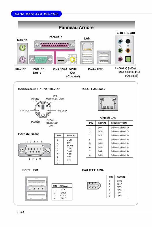
F-14
Carte Mère ATX MS-7185
Panneau Arričre
RJ-45 LAN Jack
8 1
Gigabit LAN
PIN SIGNAL DESCRIPTION
1 D0P Differential Pair 0+
2 D0N Differential Pair 0-
3 D1P Differential Pair 1+
4 D2P Differential Pair 2+
5 D2N Differential Pair 2-
6 D1N Differential Pair 1-
7 D3P Differential Pair 3+
8 D3N Differential Pair 3-
Port de série PIN SIGNAL
1 DCD2 SIN3 SOUT4 DTR5 GND6 DSR7 RTS8 CTS9 RI
1 2 3 4 5
6 7 8 9
Ports USB
1 2 3 4PIN SIGNAL 1 VCC 2 -Data 3 +Data 4 GND
Connecteur Souris/Clavier
Pin1Mouse/KBD
DATAPin2 NC
Pin3 GNDPin4 VCC
Pin5Mouse/KBD ClockPin6 NC
Clavier Port deSérie
Ports USB L-OutMic
L-In
SourisParallèle LAN
Port 1394 SPDIF Out(Coaxial)
RS-Out
CS-OutSPDIF Out(Optical)
Port IEEE 1394
PIN SIGNAL
1 PWR2 GND3 TPB-4 TPB+5 TPA-6 TPA+
2 4 6
1 3 5
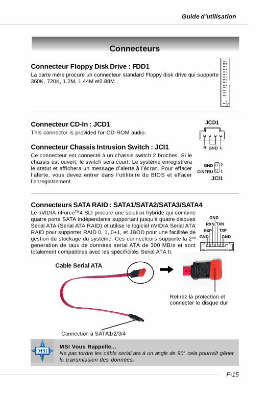
F-15
Guide d’utilisation
Connecteurs
Connecteur Floppy Disk Drive : FDD1La carte mère procure un connecteur standard Floppy disk drive qui supporte360K, 720K, 1.2M, 1.44M et2.88M .
Connecteur CD-In : JCD1This connector is provided for CD-ROM audio.
JCD1
GNDR L
GNDTXP
TXNGND
RXNRXP
GND
Connection à SATA1/2/3/4
Retirez la protection etconnecter le disque dur
Cable Serial ATA
Connecteur Chassis Intrusion Switch : JCI1Ce connecteur est connecté à un chassis switch 2 broches. Si lechassis est ouvert, le switch sera court. Le système enregistrerale statut et affichera un message d’alerte à l’écran. Pour effacerl’alerte, vous devez entrer dans l’utilitaire du BIOS et effacerl’enregistrement. JCI1
21
GNDCINTRU
MSI Vous Rappelle...Ne pas tordre les câble serial ata à un angle de 90° cela pourraît gênerla transmission des données.
Connecteurs SATA RAID : SATA1/SATA2/SATA3/SATA4Le nVIDIA nForceTM4 SLI procure une solution hybride qui combinequatre ports SATA indépendants supportant jusqu’à quatre disquesSerial ATA (Serial ATA RAID) et utilise le logiciel nVIDIA Serial ATARAID pour supporter RAID 0, 1, 0+1, et JBOD pour une facilitée degestion du stockage du système. Ces connecteurs supporte la 2nd
generation de taux de données serial ATA de 300 MB/s et sonttotalement compatibles avec les spécificités Serial ATA II.

F-16
Carte Mère ATX MS-7185
IDE1 (Connecteur IDE Primaire)Le premier disque dur doit oujours être relié à l’IDE1. Vous pouvez connecter undisque en “maître” et un autre en “esclave” sur l’IDE1.
IDE2 (Connecteur IDE Secondaire)Possibilité de connecter un disque en “maître” et un autre en “esclave” sur l’IDE2
MSI Vous Rappelle...Si vous installez 2 disques durs sur une mźme nappe, vous devezconfigurer le second disque en mode Slave (esclave) en bougeant uncavalier. Pour cela il faut vous reporter ą la documentation du disquedur concerant le changement de cavaliers (jumpers).
Connecteurs de disque dur ATA133 : IDE1 & IDE2La carte mère offre un contrôleur 32-bit Enhanced PCI IDE et Ultra DMA33/66/100/133 qui procure le PIO mode 0~4, Bus Master, et les fonctionsUltra DMA 33/66/100/133. Vosu pouvez connecter jusqu’à quatre disquesdurs, CD-ROM ou d’autres matériels.L’interface Ultra ATA133 boosts le taux de transfert de données entre le PCet le disque dur jusqu’à 133 megabytes (MB) par seconde. La nouvelleinterface est un tiers plus rapide que l’ancienne technologie Ultra ATA/100et est compatible avec l’interface Ultra ATA existente
NBFAN1
+12VGND
SENSOR
CPUFAN1
SENSOR+12VGND
SFAN1
+12VGND
SENSOR
SFAN2
+12V
GN
D
NC
Connecteurs d’alimentation de ventilateurs: CPUFAN1 / SFAN1 /SFAN2 / NBFAN1Ces connecteurs supportent le +12V. En connectant le câble au connecteur,souvenez vous que le fil rouge est positif et doit être connecté au +12V, le fil noir estla masse et doit être connecté à GND. Cette carte mère à un système de surveillancematériel intégré, vous devez donc utilsier un ventillateur avec des capteur de vitessepour utiliser cette fonction de surveillance.
MSI Vous Rappelle...1. CPUFAN1 supporte le contrôle de ventilateur. Vous pouvez installer
l’utilitaire Core Center qui contrôlera automatiquement la vitessedu ventilateur de CPU en fonction de la température du CPU.
2. Merci de vous référer aux ventilateurs de CPU recommendés sur lesite officiel d’AMD®.
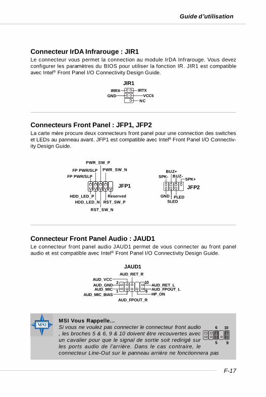
F-17
Guide d’utilisation
MSI Vous Rappelle...Si vous ne voulez pas connecter le connecteur front audio, les broches 5 & 6, 9 & 10 doivent être recouvertes avecun cavalier pour que le signal de sortie soit redirigé surles ports audio de l’arrière. Dans le cas contraire, leconnecteur Line-Out sur le panneau arrière ne fonctionnera pas
Connecteurs Front Panel : JFP1, JFP2La carte mère procure deux connecteurs front panel pour une connection des switcheset LEDs au panneau avant. JFP1 est compatible avec Intel® Front Panel I/O Connectiv-ity Design Guide.
Connecteur Front Panel Audio : JAUD1Le connecteur front panel audio JAUD1 permet de vous connecter au front panelaudio et est compatible avec Intel® Front Panel I/O Connectivity Design Guide.
JAUD1
1
2
9
10AUD_MIC
AUD_GND
AUD_MIC_BIAS
AUD_VCC
AUD_FPOUT_R
AUD_RET_R
HP_ONAUD_FPOUT_LAUD_RET_L
5
6 10
9
Connecteur IrDA Infrarouge : JIR1Le connecteur vous permet la connection au module IrDA Infrarouge. Vous devezconfigurer les paramètres du BIOS pour utiliser la fonction IR. JIR1 est compatibleavec Intel® Front Panel I/O Connectivity Design Guide.
JFP1
HDD_LED_PHDD_LED_N
RST_SW_N
RST_SW_PReserved
FP PWR/SLPFP PWR/SLP
PWR_SW_P
PWR_SW_N
GND
JFP2
SLEDPLED
SPK-BUZ+
BUZ-SPK+
JIR1IRTXIRRX
VCC5NC
GND
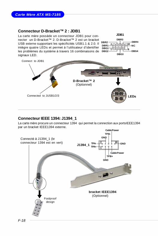
F-18
Carte Mère ATX MS-7185
Connecteur D-Bracket™ 2 : JDB1La carte mère possède un connecteur JDB1 pour con-necter un D-Bracket™ 2. D-Bracket™ 2 est un bracketUSB externe supportant les spécificités USB1.1 & 2.0. Ilintègre quatre LEDs et permet à l’utilisateur d’identifierles problèmes du système à travers 16 combinaisons designaux LED.
Connecteur IEEE 1394: J1394_1La carte mère procure un connecteur 1394 qui permet la connection aux portsIEEE1394par un bracket IEEE1394 externe.
D-Bracket™ 2(Optionnel)
Connect to JDB1
LEDsConnected to JUSB1/2/31 23 4
Foolproofdesign
Connecté à J1394_1 (leconnecteur 1394 est en vert)
bracket IEEE1394(Optionnel)
JDB1
1
2
9
10
DBG1DBR1
DBG2
DBR2
DBG3
DBR3
DBG4
DBR4NC
J1394_11
2 10
TPA+TPA-
GND
GND
TPB+
TPB-
Cable Power
GND
Cable Power
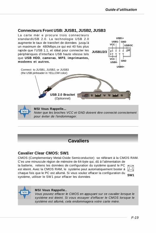
F-19
Guide d’utilisation
Connecteurs Front USB: JUSB1, JUSB2, JUSB3La carte mèr e procure t rois connec teursstandardUSB 2.0. La technologie USB 2.0augmente le taux de transfert de données jusqu’àun maximum de 480Mbps,ce qui est 40 fois plusrapide que l’USB 1.1, et idéal pour connecter lespériphériques d’interface USB haute vitesse telsque USB HDD, cameras, MP3, imprimantes,modems et autres.
MSI Vous Rappelle...Noter que les broches VCC et GND doivent être connecté correctementpour éviter de l’endommager.
Cavalier Clear CMOS: SW1CMOS (Complementary Metal-Oxide Semiconductor) se référant à la CMOS RAM.C’es une minuscule région de mémoire de 64-byte qui, dû à l’alimentation dela batterie, retiens les données de configuration du système quand le PCest éteint. Avec la CMOS RAM, le système peut automatiquement booter àchaque fois que le PC est allumé. Si vous voulez effacer la configuration dusystème, utiliser le SW1 pour effacer les données
Cavaliers
MSI Vous Rappelle..Vous pouvez effacer le CMOS en appuyant sur ce cavalier lorsque lesystème est éteint. Si vous essayer d’effacer le CMOS lorsque lesystème est allumé, cela endommagera votre carte mère.
JUSB1/2/3
VCCUSB0-
USB0+
GND
VCCUSB1-
USB1+GND
USBOC
1 2 10
Connect to JUSB1, JUSB2, or JUSB3(the USB pinheader in YELLOW color)
USB 2.0 Bracket(Optionnel)
SW1
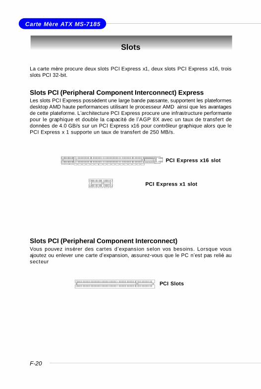
F-20
Carte Mère ATX MS-7185
Slots
La carte mère procure deux slots PCI Express x1, deux slots PCI Express x16, troisslots PCI 32-bit.
Slots PCI (Peripheral Component Interconnect) ExpressLes slots PCI Express possèdent une large bande passante, supportent les plateformesdesktop AMD haute performances utilisant le processeur AMD ainsi que les avantagesde cette plateforme. L’architecture PCI Express procure une infrastructure performantepour le graphique et double la capacité de l’AGP 8X avec un taux de transfert dedonnées de 4.0 GB/s sur un PCI Express x16 pour contrôleur graphique alors que lePCI Express x 1 supporte un taux de transfert de 250 MB/s.
Slots PCI (Peripheral Component Interconnect)Vous pouvez insérer des cartes d’expansion selon vos besoins. Lorsque vousajoutez ou enlever une carte d’expansion, assurez-vous que le PC n’est pas relié ausecteur
PCI Slots
PCI Express x1 slot
PCI Express x16 slot
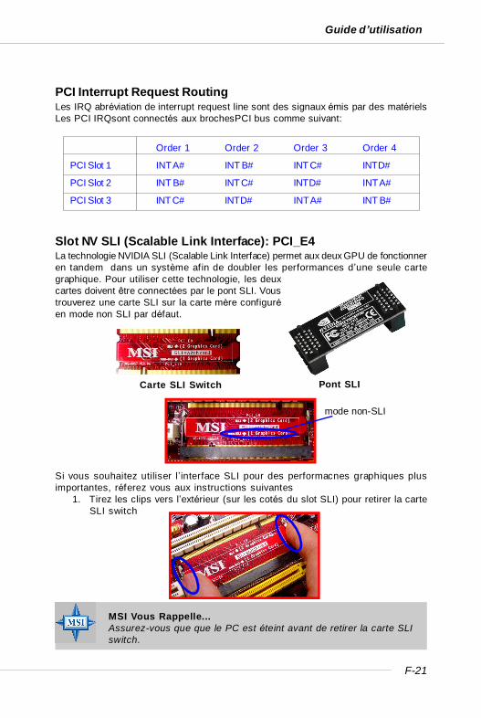
F-21
Guide d’utilisation
PCI Interrupt Request RoutingLes IRQ abréviation de interrupt request line sont des signaux émis par des matérielsLes PCI IRQsont connectés aux brochesPCI bus comme suivant:
MSI Vous Rappelle...Assurez-vous que que le PC est éteint avant de retirer la carte SLIswitch.
Si vous souhaitez utiliser l’interface SLI pour des performacnes graphiques plusimportantes, réferez vous aux instructions suivantes
1. Tirez les clips vers l’extérieur (sur les cotés du slot SLI) pour retirer la carteSLI switch
Pont SLI
Order 1 Order 2 Order 3 Order 4
PCI Slot 1 INT A# INT B# INT C# INT D#
PCI Slot 2 INT B# INT C# INT D# INT A#
PCI Slot 3 INT C# INT D# INT A# INT B#
Carte SLI Switch
mode non-SLI
Slot NV SLI (Scalable Link Interface): PCI_E4La technologie NVIDIA SLI (Scalable Link Interface) permet aux deux GPU de fonctionneren tandem dans un système afin de doubler les performances d’une seule cartegraphique. Pour utiliser cette technologie, les deuxcartes doivent être connectées par le pont SLI. Voustrouverez une carte SLI sur la carte mère configuréen mode non SLI par défaut.

F-22
Carte Mère ATX MS-7185
2. Retirez la carte SLI switch. La retournez dans le sens Mode SLI puis l’insérerà un angle de 45 degrés.
3. Apuuyez sur la carte SLI switch. Les clips sur les cotés du slot SLIserefermeront automatiquement. La carte sera sécurisée dans les slots. Avantd’installer ou de retirer la carte switch SLI, assurez-vous que le PC est éteint.
MSI Vous Rappelle...1. Les photos de la carte mère servent uniquement de démonstration
et sont utilisées à titre indicatif. L’apparence de votre carte mèrepeut varier selon le modèle possédé.
2. Si vous souhaitez n’installer qu’une carte graphique 16x, assurez-vous que : a. votre carte graphique est installée sur le slot PCI_E1;
b. Le switch SLI est installé en mode non-SLI.3. Si vous avez l’intention d’installer deux cartes graphiques 16x,
assurez-vous que: a. ces deux cartes sont de même marque etavec les même spécificités; b. Le switch SLI est en mode SLI.
Pont SLI
4. Après avoir configurer le switch en mode SLI, vous pouvez désormais in-staller deux cartes graphiques sur les slots PCI Express 16x. Avec deuxcartes installées, le pont SLI est nécessaire pour connecter les deux partiesdorées des deux cartes graphiques. Merci de noter qu’après cette installation,seules les sorties vidéo de la première carte fonctionneront. Par conséquent,votre écran doit être connecter sur la première carte graphique.
Mode SLI
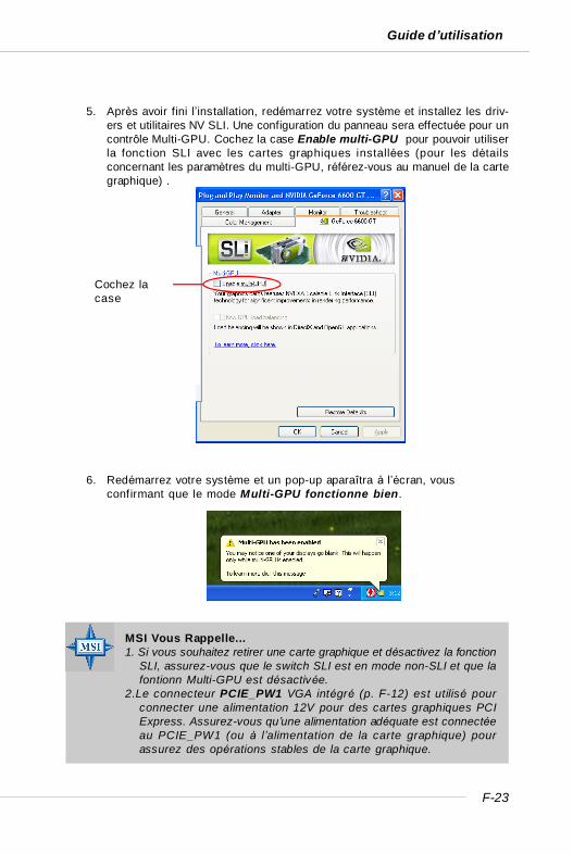
F-23
Guide d’utilisation
5. Après avoir fini l’installation, redémarrez votre système et installez les driv-ers et utilitaires NV SLI. Une configuration du panneau sera effectuée pour uncontrôle Multi-GPU. Cochez la case Enable multi-GPU pour pouvoir utiliserla fonction SLI avec les cartes graphiques installées (pour les détailsconcernant les paramètres du multi-GPU, référez-vous au manuel de la cartegraphique) .
6. Redémarrez votre système et un pop-up aparaîtra à l’écran, vousconfirmant que le mode Multi-GPU fonctionne bien.
Cochez lacase
MSI Vous Rappelle...1. Si vous souhaitez retirer une carte graphique et désactivez la fonction
SLI, assurez-vous que le switch SLI est en mode non-SLI et que lafontionn Multi-GPU est désactivée.
2.Le connecteur PCIE_PW1 VGA intégré (p. F-12) est utilisé pourconnecter une alimentation 12V pour des cartes graphiques PCIExpress. Assurez-vous qu’une alimentation adéquate est connectéeau PCIE_PW1 (ou à l’alimentation de la carte graphique) pourassurez des opérations stables de la carte graphique.
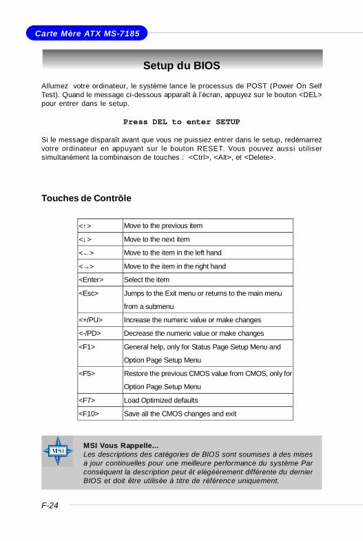
F-24
Carte Mère ATX MS-7185
Setup du BIOS
Touches de Contrōle
MSI Vous Rappelle...Les descriptions des catégories de BIOS sont soumises à des misesà jour continuelles pour une meilleure performance du système Parconséquent la description peut êt elégéèrement différente du dernierBIOS et doit être utilisée à titre de référence uniquement.
Allumez votre ordinateur, le système lance le processus de POST (Power On SelfTest). Quand le message ci-dessous apparaît à l’écran, appuyez sur le bouton <DEL>pour entrer dans le setup.
Press DEL to enter SETUP
Si le message disparaît avant que vous ne puissiez entrer dans le setup, redémarrezvotre ordinateur en appuyant sur le bouton RESET. Vous pouvez aussi utilisersimultanément la combinaison de touches : <Ctrl>, <Alt>, et <Delete>.
<↑> Move to the previous item
<↓> Move to the next item
<←> Move to the item in the left hand
<→> Move to the item in the right hand
<Enter> Select the item
<Esc> Jumps to the Exit menu or returns to the main menu
from a submenu
<+/PU> Increase the numeric value or make changes
<-/PD> Decrease the numeric value or make changes
<F1> General help, only for Status Page Setup Menu and
Option Page Setup Menu
<F5> Restore the previous CMOS value from CMOS, only for
Option Page Setup Menu
<F7> Load Optimized defaults
<F10> Save all the CMOS changes and exit
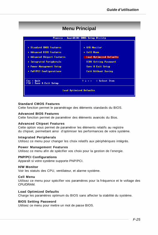
F-25
Guide d’utilisation
Menu Principal
Standard CMOS FeaturesCette fonction permet le paramétrage des éléments standards du BIOS.
Advanced BIOS FeaturesCette fonction permet de paramétrer des éléments avancés du Bios.
Advanced Chipset FeaturesCette option vous permet de paramétrer les éléments relatifs au registredu chipset, permettant ainsi d’optimiser les performances de votre système.
Integrated PeripheralsUtilisez ce menu pour changer les choix relatifs aux périphériques intégrés.
Power Management FeaturesUtilisez ce menu afin de spécifier vos choix pour la gestion de l’energie.
PNP/PCI ConfigurationsApparaît si votre système supporte PNP/PCI.
H/W MonitorVoir les statuts des CPU, ventilateur, et alarme système.
Cell MenuUtilisez ce menu pour spécifier vos paramètres pour la fréquence et le voltage desCPU/DRAM.
Load Optimized DefaultsCharge les paramètres optimum du BIOS sans affecter la stabilité du système.
BIOS Setting PasswordUtilisez ce menu pour mettre un mot de passe BIOS.
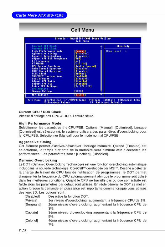
F-26
Carte Mère ATX MS-7185
Cell Menu
Current CPU / DDR ClockVitesse d’horloge des CPU & DDR. Lecture seule.
High Performance ModeSélectionner les paramètres the CPU/FSB. Options: [Manual], [Optimized]. Lorsque[Optimized] est sélectionné, le système utilisera des paramètres d’overclocking pourle CPU/FSB. Sélectionner [Manual] pour le mode normal CPU/FSB.
Aggressive timingCet élément permet d’activer/désactiver l’horloge mémoire. Quiand [Enabled] estselectionné, le temps d’attente de la mémoire sera diminué af in d’accroître lesperformances. Les paramètres sont : [Enabled], [Disabled].
Dynamic OverclockingLe DOT (Dynamic Overclocking Technology) est une fonction overclocking automatiqueinclut dans la nouvelle technologie CoreCellTM développée par MSITM. Déstiné à détecterla charge de travail du CPU lors de l’utilisation de programmes, le DOT permetd’augmenter la fréquence du CPU automatiquement afin que le programme soit utilisédans les meilleures conditions. Quand le CPU ne travaille pas ou que son activité estfaible alors les paramètres par défaut sont utilisés. En règle général, le DOT se met enaction lorsque la demande en puissance est importante comme lorsque vous utilisezdes jeux 3D. Les options sont :
[Disabled] Désactive la fonction DOT.[Private] 1er niveau d’overclocking, augmentant la fréquence CPU de 1%.[Sergeant] 2ème niveau d’overclocking, augmentant la fréquence CPU de
3%.[Captain] 3ème niveau d’overclocking augmentant la fréquence CPU de
5%.[Colonel] 4ème niveau d’overclocking, augmentant la fréquence CPU de
7%.
F-27
Guide d’utilisation
[General] 5ème niveau d’overclocking, augmentant la fréquence CPU de9%.
[Commander] 6ème niveau d’overclocking, augmentant la fréquence CPU de11%
Adjust CPU FSB FrequencyCet élément vous permet de sélectionner la fréquence du FSB du CPU (en MHz).Choisir un nombre entre [200]~[400] pour la fréquence voulue.
HT FrequencyCe paramètre spécifie la fréquence maximale d’exploitation. Les options: [1x], [1.5x],[2x], [2.5x], [3x], [4x], [5x].
HT WidthCe champs vous permet de paramétrer l’HT Width entre CPU & Chip.- mark means Chipto CPU HT Width.
CPU Spread SpectrumCe paramètre permet d’activer/désactiver la fonction de Spread Spectrum CPU. Lorsquevous faites de l’overclocking sur le FSB, veuillez toujours sélectionner [Disabled].Les options : [Center Spread], [Disabled].
SATA Spread SpectrumCe paramètre permet d’activer/désactiver la fonction de Spread Spectrum SATA. Lesoptions: [Disabled], [Down Spread].
PCIE Spread SpectrumCe paramètre permet d’activer/désactiver la fonction de Spread Spectrum CPU. Lorsquevous faites de l’overclocking sur le FSB, veuillez toujours sélectionner [Disabled].Les options : [Disabled], [Down Spread].
PCIE ClockCe paramètre détermine la fréquence d’horloge des slots PCI Expresss. Setting options:[100MHz] ~ [145MHz].
Instructions SSE/SSE2Cet élément active/désactive les instructions SSE/SSE2. Le SSE (Streaming SIMDExtensions) est introduit avec les processeurs Pentium III. Les extensions SSE con-sis tent en un nouveau jeu d’ instructions pour le registre. Ces fonctions sontdéveloppées pour des instructions simples ou multiples (SIMD).Les SSE2 (Streaming SIMD Extensions 2) sont introduites avec les processeurs
MSI Vous Rappelle...Même lorsque le Dynamic Overclocking Technology est plus stableque l’ overclocking manuel, cela est toujours risqué. Nous voussuggérons de vous assurez tout d’abord que votre CPU supportel’overclocking régulier. Si votre PC devient instable ou reboot, il estpréférable de désactiver le Dynamic Overclocking ou de baisser leniveau des options d’overclocking. Par ailleurs, si vous souhaitezoverclocker manuellement, vous devez également désactiver lafonction Dynamic OverClocking auparavant.
F-28
Carte Mère ATX MS-7185
Pentium 4 et Intel Xeon. Elles consistent en de nouveaux jeux d’instructions quifonctionnent avec les registres XXM et MXCSR pour améliorer les performances SIMDdes opérations en virgules flottantes et en valeurs intégrées. Plusieurs de cesnouvelles instructions fonctionnent avec le registre MMX. Options: [Enabled], [Disabled].
Cool’n’Quiet controlCette fonction est exclusivement réservée aux processeurs AMD Athlon, elle pro-cure une fonction de détection de la température du CPU permettant ainsi d’éviter lasurchauffe. Les options: [Disabled], [Auto].
Adjust CPU RatioCet élément vous permet d’ajuster le ratio du CPU. En mode [Startup] cela permetau CPU de fonctionner plus rapidement. Les options : [Startup], [x4]~[x25].
Adjust CPU VIDCe champs vous permet d’ajuster le CPU VID. En position [Startup] cela permet au CPUde fonctionner avec le VID par défaut détecter par le système. Paramètres: [Startup],[1.550V] ~ [0.825V].
Extra CPU VoltageCe paramètre vous permet d’ajouter d’autre voltage au CPU. Paramètres: [By CPUVID], [Over VID 3.3%], [Over VID 6.6%],[Over VID 8.3%].
CPU VoltageCe paramète montre le voltage du CPU.
Memory VoltageModifier le voltage DDR peut augmenter la vitesse de la DDR. Tous les changementspeuvent entraîner une instabilité, par conséquent l’utilisation d’un paramètre modifiéedoit pas se faire de façon défintive mais temporaire.
NF4 VoltageNF4 voltage est ajustable dans ce champs.
MSI Vous Rappelle...Afin d’assurer la stabilité de la fonction Cool'n'Quiet, il est recommandéde mettre de la mémoire sur le DIMM1.
MSI Vous Rappelle...Les paramčtres de couleurs différentes pour CPU Voltage,Memory Voltage et AGP Voltage vous aident ą vérifier si lesparamčtres pour votre systčme sont correctes.Gris: Paramčtres par défaut.Jaune: Paramčtres hautes performances.Rouge: Paramčtres non recommandés et systčme instable.Changer le CPU Voltage, Memory Voltage et AGP Voltage peutentraīner une instabilité, c ’est pourquoi nous ne recommandons pasde changer ces paramčtres pour une utilisation prolongée.