Embed Size (px)
Citation preview

Addressable Fire AlarmControl Panel
MS-9200(C)/MS-9200E
EDocument #51003 01/11/02 Rev.© 2002 Fire•Lite
PN: 51003:E ECN 02-014

LimWarLg.p65 01/10/2000
An automatic fire alarm system–typically made up of smokedetectors, heat detectors, manual pull stations, audible warn-ing devices, and a fire alarm control with remote notificationcapability–can provide early warning of a developing fire.Such a system, however, does not assure protection againstproperty damage or loss of life resulting from a fire.
The Manufacturer recommends that smoke and/or heat detec-tors be located throughout a protected premise following therecommendations of the current edition of the National FireProtection Association Standard 72 (NFPA 72),manufacturer's recommendations, State and local codes, andthe recommendations contained in the Guide for Proper Useof System Smoke Detectors, which is made available at nocharge to all installing dealers. A study by the Federal Emer-gency Management Agency (an agency of the United Statesgovernment) indicated that smoke detectors may not go off inas many as 35% of all fires. While fire alarm systems are de-signed to provide early warning against fire, they do not guar-antee warning or protection against fire. A fire alarm systemmay not provide timely or adequate warning, or simply may notfunction, for a variety of reasons:
Smoke detectors may not sense fire where smoke cannotreach the detectors such as in chimneys, in or behind walls, onroofs, or on the other side of closed doors. Smoke detectorsalso may not sense a fire on another level or floor of a build-ing. A second-floor detector, for example, may not sense afirst-floor or basement fire.
Particles of combustion or "smoke" from a developing firemay not reach the sensing chambers of smoke detectors be-cause:
• Barriers such as closed or partially closed doors, walls, orchimneys may inhibit particle or smoke flow.
• Smoke particles may become "cold," stratify, and not reachthe ceiling or upper walls where detectors are located.
• Smoke particles may be blown away from detectors by airoutlets.
• Smoke particles may be drawn into air returns beforereaching the detector.
The amount of "smoke" present may be insufficient to alarmsmoke detectors. Smoke detectors are designed to alarm atvarious levels of smoke density. If such density levels are notcreated by a developing fire at the location of detectors, thedetectors will not go into alarm.
Smoke detectors, even when working properly, have sensinglimitations. Detectors that have photoelectronic sensingchambers tend to detect smoldering fires better than flamingfires, which have little visible smoke. Detectors that have ion-izing-type sensing chambers tend to detect fast-flaming firesbetter than smoldering fires. Because fires develop in differ-ent ways and are often unpredictable in their growth, neithertype of detector is necessarily best and a given type of detec-tor may not provide adequate warning of a fire.
Smoke detectors cannot be expected to provide adequatewarning of fires caused by arson, children playing withmatches (especially in bedrooms), smoking in bed, and violentexplosions (caused by escaping gas, improper storage offlammable materials, etc.).
Heat detectors do not sense particles of combustion andalarm only when heat on their sensors increases at a prede-termined rate or reaches a predetermined level. Rate-of-riseheat detectors may be subject to reduced sensitivity over time.For this reason, the rate-of-rise feature of each detectorshould be tested at least once per year by a qualified fire pro-tection specialist. Heat detectors are designed to protectproperty, not life.
IMPORTANT! Smoke detectors must be installed in thesame room as the control panel and in rooms used by the sys-tem for the connection of alarm transmission wiring, communi-cations, signaling, and/or power. If detectors are not so lo-cated, a developing fire may damage the alarm system, crip-pling its ability to report a fire.
Audible warning devices such as bells may not alert peopleif these devices are located on the other side of closed orpartly open doors or are located on another floor of a building.Any warning device may fail to alert people with a disability orthose who have recently consumed drugs, alcohol or medica-tion. Please note that:
• Strobes can, under certain circumstances, cause seizuresin people with conditions such as epilepsy.
• Studies have shown that certain people, even when theyhear a fire alarm signal, do not respond or comprehend themeaning of the signal. It is the property owner's responsibil-ity to conduct fire drills and other training exercise to makepeople aware of fire alarm signals and instruct them on theproper reaction to alarm signals.
• In rare instances, the sounding of a warning device cancause temporary or permanent hearing loss.
A fire alarm system will not operate without any electricalpower. If AC power fails, the system will operate from standbybatteries only for a specified time and only if the batterieshave been properly maintained and replaced regularly.
Equipment used in the system may not be technically com-patible with the control. It is essential to use only equipmentlisted for service with your control panel.
Telephone lines needed to transmit alarm signals from apremise to a central monitoring station may be out of serviceor temporarily disabled. For added protection against tele-phone line failure, backup radio transmission systems are rec-ommended.
The most common cause of fire alarm malfunction is inade-quate maintenance. To keep the entire fire alarm system inexcellent working order, ongoing maintenance is required perthe manufacturer's recommendations, and UL and NFPA stan-dards. At a minimum, the requirements of Chapter 7 of NFPA72 shall be followed. Environments with large amounts ofdust, dirt or high air velocity require more frequent mainte-nance. A maintenance agreement should be arrangedthrough the local manufacturer's representative. Maintenanceshould be scheduled monthly or as required by National and/or local fire codes and should be performed by authorized pro-fessional fire alarm installers only. Adequate written recordsof all inspections should be kept.
While a fire alarm system may lower insurancerates, it is not a substitute for fire insurance!Fire Alarm System Limitations

LimWarLg.p65 01/10/2000
WARNING - Several different sources of power can be con-nected to the fire alarm control panel. Disconnect all sourcesof power before servicing. Control unit and associated equip-ment may be damaged by removing and/or inserting cards,modules, or interconnecting cables while the unit is energized.Do not attempt to install, service, or operate this unit until thismanual is read and understood.
CAUTION - System Reacceptance Test after SoftwareChanges. To ensure proper system operation, this productmust be tested in accordance with NFPA 72 Chapter 7 afterany programming operation or change in site-specific soft-ware. Reacceptance testing is required after any change, ad-dition or deletion of system components, or after any modifica-tion, repair or adjustment to system hardware or wiring.
All components, circuits, system operations, or software func-tions known to be affected by a change must be 100% tested.In addition, to ensure that other operations are not inadvert-ently affected, at least 10% of initiating devices that are notdirectly affected by the change, up to a maximum of 50 de-vices, must also be tested and proper system operation veri-fied.
This system meets NFPA requirements for operation at0-49° C/32-120° F and at a relative humidity of 85% RH (non-condensing) at 30° C/86° F. However, the useful life of thesystem's standby batteries and the electronic componentsmay be adversely affected by extreme temperature rangesand humidity. Therefore, it is recommended that this systemand all peripherals be installed in an environment with a nomi-nal room temperature of 15-27° C/60-80° F.
Verify that wire sizes are adequate for all initiating andindicating device loops. Most devices cannot tolerate morethan a 10% I.R. drop from the specified device voltage.
Like all solid state electronic devices, this system mayoperate erratically or can be damaged when subjected to light-ning-induced transients. Although no system is completelyimmune from lightning transients and interferences, propergrounding will reduce susceptibility. Overhead or outsideaerial wiring is not recommended, due to an increased sus-ceptibility to nearby lightning strikes. Consult with the Techni-cal Services Department if any problems are anticipated orencountered.
Disconnect AC power and batteries prior to removing or in-serting circuit boards. Failure to do so can damage circuits.
Remove all electronic assemblies prior to any drilling, filing,reaming, or punching of the enclosure. When possible, makeall cable entries from the sides or rear. Before making modifi-cations, verify that they will not interfere with battery, trans-former, and printed circuit board location.
Do not tighten screw terminals more than 9 in-lbs.Over-tightening may damage threads, resulting in reducedterminal contact pressure and difficulty with screw terminalremoval.
Though designed to last many years, system componentscan fail at any time. This system contains static-sensitivecomponents. Always ground yourself with a proper wrist strapbefore handling any circuits so that static charges are re-moved from the body. Use static-suppressive packagingto protect electronic assemblies removed from the unit.
Follow the instructions in the installation, operating, andprogramming manuals. These instructions must be followedto avoid damage to the control panel and associatedequipment. FACP operation and reliability depend uponproper installation by authorized personnel.
Adherence to the following will aid in problem-freeinstallation with long-term reliability:
WARNING: This equipment generates, uses, and canradiate radio frequency energy and if not installed andused in accordance with the instruction manual, maycause interference to radio communications. It hasbeen tested and found to comply with the limits for classA computing device pursuant to Subpart B of Part 15 ofFCC Rules, which is designed to provide reasonableprotection against such interference when operated in acommercial environment. Operation of this equipment ina residential area is likely to cause interference, in whichcase the user will be required to correct the interferenceat his own expense.
Canadian RequirementsThis digital apparatus does not exceed the Class Alimits for radiation noise emissions from digitalapparatus set out in the Radio Interference Regulationsof the Canadian Department of Communications.
Le present appareil numerique n'emet pas de bruitsradioelectriques depassant les limites applicables auxappareils numeriques de la classe A prescrites dans leReglement sur le brouillage radioelectrique edicte par leministere des Communications du Canada.
FCC Warning
Installation Precautions

4 Document #51003 Rev.E 01/11/02 P/N 51003:E
Notes

Document 51003 Rev. E 01/11/02 P/N: 51003:E 5
CHAPTER 1: Product Description .........................................................................................................................91.1: Features .......................................................................................................................................................91.2: Specifications ..............................................................................................................................................111.3: Controls and Indicators ...............................................................................................................................121.4: Circuits ........................................................................................................................................................131.5: Components.................................................................................................................................................13
1.5.1: Intelligent Addressable Detectors: Newer Series..............................................................................141.5.2: Intelligent Addressable Modules: Newer Series ...............................................................................151.5.3: 300 Series Intelligent Addressable Devices......................................................................................151.5.4: Addressable Device Accessories.......................................................................................................16
1.6: Optional Modules ........................................................................................................................................161.7: Accessories..................................................................................................................................................17
1.7.1: Dress Panel........................................................................................................................................171.7.2: Battery Box .......................................................................................................................................181.7.3: CHG-120F Battery Charger ..............................................................................................................181.7.4: Annunciators .....................................................................................................................................201.7.5: FCPS-24F/E Remote Field Charger Power Supply for System Power Expansion...........................22
CHAPTER 2: Installation.........................................................................................................................................232.1: Backbox Mounting......................................................................................................................................242.2: Power...........................................................................................................................................................25
2.2.1: AC Power and Earth Ground Connections .......................................................................................252.2.2: Battery Power....................................................................................................................................252.2.3: DC Power Output Connections .........................................................................................................25
2.3: Standard Relays...........................................................................................................................................262.4: Notification Appliance Circuits ..................................................................................................................262.5: Annunciator and PC/Printer Circuits...........................................................................................................262.6: UL Power-limited Wiring Requirements ....................................................................................................272.7: Wiring the Signaling Line Circuit ...............................................................................................................28
2.7.1: Device Capacity ................................................................................................................................282.7.2: Surge Suppression.............................................................................................................................282.7.3: Installation.........................................................................................................................................28
2.8: Optional Modules ........................................................................................................................................292.8.1: UDACT-F Universal Digital Alarm Communicator/Transmitter.....................................................292.8.2: ACM-8RF Relay Control Module ....................................................................................................322.8.3: RTM-8F Option Module Installation ................................................................................................33
2.9: Printer/PC and Terminal Mode Annunciator Interface ...............................................................................35
CHAPTER 3: Programming/Read Status ..............................................................................................................373.1: Initial Power-up...........................................................................................................................................383.2: Programming...............................................................................................................................................393.3: Program Change - Level One......................................................................................................................40
3.3.1: Clear ..................................................................................................................................................403.3.2: Autoprogram .....................................................................................................................................403.3.3: Point Edit...........................................................................................................................................443.3.4: System Edit .......................................................................................................................................453.3.5: Password Change ..............................................................................................................................463.3.6: Load ..................................................................................................................................................47
3.4: Program Change - Level 2 ..........................................................................................................................473.4.1: Disable ..............................................................................................................................................483.4.2: Clear History .....................................................................................................................................493.4.3: Walktest.............................................................................................................................................49
Table of Contents

Table of Contents
6 Document 51003 Rev. E 01/11/02 P/N: 51003:E
3.4.4: Set Time and Date .............................................................................................................................503.4.5: Check.................................................................................................................................................50
CHAPTER 4: Operating Instructions .....................................................................................................................514.1: Control Switches (Keys)..............................................................................................................................51
4.1.1: Acknowledge/Step ............................................................................................................................514.1.2: Alarm Silence....................................................................................................................................514.1.3: Drill Hold 2 Sec.................................................................................................................................514.1.4: System Reset .....................................................................................................................................51
4.2: LED Indicators ............................................................................................................................................524.3: Normal Operation........................................................................................................................................524.4: Trouble Operation........................................................................................................................................534.5: Alarm Operation..........................................................................................................................................554.6: Supervisory Operation.................................................................................................................................554.7: NAC (Notification Appliance Circuit) Operation .......................................................................................564.8: Control-By-Event Operation .......................................................................................................................564.9: Detector Functions.......................................................................................................................................564.10: Time Functions: Real-Time Clock ............................................................................................................574.11: Coded Operation - NAC 1 and NAC 2......................................................................................................574.12: Presignal ....................................................................................................................................................574.13: Special System Timers ..............................................................................................................................57
4.13.1: Silence Inhibit Timer (None or 60 Seconds)...................................................................................574.13.2: Auto-silence Timer (None or 10 Minutes) ......................................................................................574.13.3: Trouble Reminder............................................................................................................................574.13.4: Alarm Verification...........................................................................................................................584.13.5: Waterflow Circuits Operation .........................................................................................................584.13.6: Disable/Enable Operation ...............................................................................................................58
4.14: Style 6 Wiring............................................................................................................................................584.15: Read Status ................................................................................................................................................58
Appendix A: Power Supply Calculations ............................................................................................................61
A.1: The AC Branch Circuit ..............................................................................................................................61A.2: The Main Power Supply ............................................................................................................................62
Appendix B: Software Zones ................................................................................................................................65
Appendix C: LCD-40 Series Annunciator Wiring ..............................................................................................72
Appendix D: ACS and LDM Series Wiring ........................................................................................................73
Appendix E: NFPA Standard-Specific Requirements .......................................................................................77
Appendix F: Wire Requirements .........................................................................................................................83
Appendix G: Screen Options Flowchart ..............................................................................................................84
Document #51003 Rev.E 01/11/02 P/N 51003:E 7
This control panel has been designed to comply with standards set forth by the following regulatory agencies:
• Underwriters Laboratories Standard UL 864
• NFPA 72 National Fire Alarm Code
• CAN/ULC - S527-99 Standard for Control Units for Fire Alarm Systems
NFPA Standards
This Fire Alarm Control Panel complies with the following NFPA Fire Alarm Codes:
NFPA 72 National Fire Alarm Code for Central Station Fire Alarm Systems Protected Premises Unit (Automatic, Manual and Waterflow) - requires UDACT-F, Local Fire Alarm Systems (Automatic, Manual Waterflow and Sprinkler Supervisory), Auxiliary Fire Alarm Systems (Automatic, Manual and Waterflow) - requires RTM-8F, Remote Station Fire Alarm Systems (Automatic, Manual and Waterflow) - requires RTM-8F or UDACT-F, Proprietary Fire Alarm Systems (Automatic, Manual and Waterflow) Protected Premises Unit, Automatic Fire Detectors, Installaltion, Maintenance & Use of Notification Appliances for Fire Alarm Systems and Testing Procedures for Fire Alarm Systems.
Underwriters Laboratories Documents:
UL 38 Manually Actuated Signaling BoxesUL 217 Smoke Detectors, Single and Multiple StationUL 228 Door Closers–Holders for Fire Protective Signaling SystemsUL 268 Smoke Detectors for Fire Protective Signaling SystemsUL 268A Smoke Detectors for Duct ApplicationsUL 346 Waterflow Indicators for Fire Protective Signaling SystemsUL 464 Audible Signaling AppliancesUL 521 Heat Detectors for Fire Protective Signaling SystemsUL 864 Standard for Control Units for Fire Protective Signaling SystemsUL 1076 Proprietary Burglar Alarm SystemsUL 1481 Power Supplies for Fire Protective Signaling SystemsUL 1638 Visual Signaling AppliancesUL 1971 Signaling Devices for Hearing Impaired
CAN/ULC - S524-01 Standard for Installation of Fire Alarm Systems
Other:
EIA-485 and EIA-232 Serial Interface StandardsNEC Article 250 GroundingNEC Article 300 Wiring MethodsNEC Article 760 Fire Protective Signaling SystemsApplicable Local and State Building CodesRequirements of the Local Authority Having Jurisdiction (LAHJ)
Fire•Lite Documents
Fire•Lite Device Compatibility Document Document #15384 Annunciator Modules Document #15390AFM-16ATF and AFM-32AF Annunciators Document #15970AFM-16AF Annunciator Document #15210MS-5012 Communicator Document #15465PK-9200 Off Line Programming Utility Document #15677PK-9200W Off Line Programming Utility Document #50684UDACT-F Communicator/Transmitter Document #50049FCPS-24F Field Charger/Power Supply Document #50079CHG-120F Battery Charger Document #50888LDM Series Lamp Driver Modules Document #50055LCD-40 Remote Fire Annunciaotr Document #50327ACM-8RF Relay Control Manual Document #50362
Before proceeding, the installer should be familiar with the following documents.
8 Document #51003 Rev.E 01/11/02 P/N 51003:E
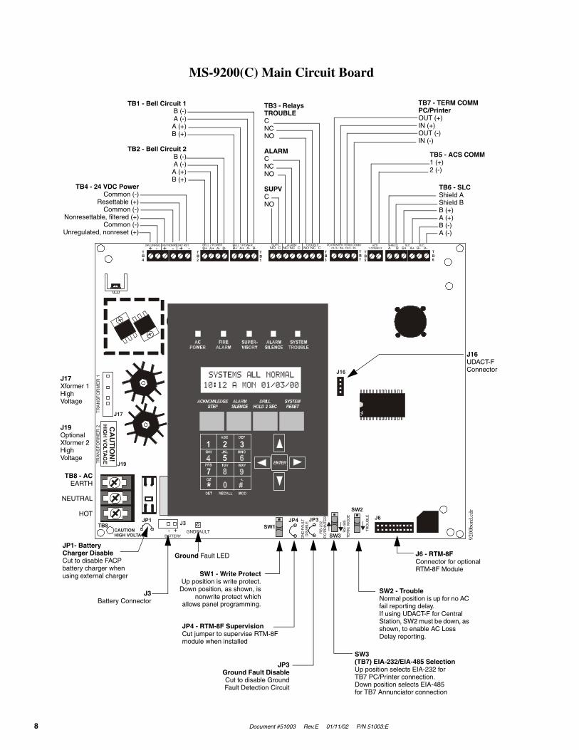
MS-9200(C) Main Circuit Board
24V UNREG 24V NONRS 24V RST BELL 2 POWER BELL 1 POWER SUPV ALARM TROUBLE PC/PRINTER TERM COMM
GN
D F
AULT
DIS
ABLE
TRAN
SFO
RM
ER 1
TRAN
SFO
RM
ER 2
- +BATTERY
RS-
232
PC/P
RIN
TER
RS-
485
TER
M. M
OD
E
TRO
UBL
E
+ - + - + - B+ A+ A- B- B+ A+ A- B- NO C NO NC C NO NC C A B B+ A+ B- A- 1 COMM 2ACS SHIELD SLC SLC
OUT+ IN+ OUT- IN-TB4
TB2
TB1
TB3
TB7
TB5
TB6
J16
J6JP3JP1
CAUTIONHIGH VOLTAGE
J3TB8
J19
J17
JP4SW1
SW3
SW2
CA
UTIO
N!
HIG
H VO
LTAG
E
GNDFAULT
J16UDACT-FConnector
TB4 - 24 VDC PowerCommon (-)
Resettable (+)Common (-)
Nonresettable, filtered (+)Common (-)
Unregulated, nonreset (+)
TB1 - Bell Circuit 1B (-)A (-)A (+)B (+)
TB2 - Bell Circuit 2B (-)A (-)A (+)B (+)
TB6 - SLCShield AShield BB (+)A (+)B (-)A (-)
TB5 - ACS COMM1 (+)2 (-)
TB7 - TERM COMMPC/PrinterOUT (+)IN (+)OUT (-)IN (-)
TB3 - RelaysTROUBLECNCNO
ALARMCNCNO
SUPVCNO
J17Xformer 1HighVoltage
J19OptionalXformer 2HighVoltage
TB8 - ACEARTH
NEUTRAL
HOT
JP1- Battery Charger DisableCut to disable FACP battery charger when using external charger
J3Battery Connector
JP3Ground Fault DisableCut to disable GroundFault Detection Circuit
SW3(TB7) EIA-232/EIA-485 SelectionUp position selects EIA-232 for TB7 PC/Printer connection.Down position selects EIA-485 for TB7 Annunciator connection
SW2 - TroubleNormal position is up for no AC fail reporting delay.If using UDACT-F for Central Station, SW2 must be down, as shown, to enable AC Loss Delay reporting.
J6 - RTM-8FConnector for optional RTM-8F Module
JP4 - RTM-8F SupervisionCut jumper to supervise RTM-8F module when installed
SW1 - Write ProtectUp position is write protect.
Down position, as shown, isnonwrite protect which
allows panel programming.
Ground Fault LED
9200
bord
.cdr

Document #51003 Rev.E 01/11/02 P/N 51003:E 9
Product Description
CHAPTER 1 Product Description
The Fire•Lite MS-9200(C) is a compact, cost effective, addressable FACP (Fire Alarm Control Panel) with an exten-sive list of powerful features. The combination of Fire•Lite's newer series devices and legacy 300 Series Addressable Devices, along with the MS-9200 FACP offers the latest in fire protection technology. The power supply and all elec-tronics are contained on a single circuit board housed in an attractive metal cabinet, providing a complete fire control system for most applications. Optional modules, which plug into the main circuit board, are available for special functions. Available accessories include LED, graphic and LCD annunciators, digital communicator, local down-loading software and remote power expansion. The MS-9200E offers the same features as the MS-9200(C) but allows connection to 220/240 VAC input.
Note: Unless otherwise specified, the term MS-9200 is used in this manual to refer to both the MS-9200(C) and the MS-9200E FACPs (Fire Alarm Control Panels).
1.1 Features
• Single standard SLC loop which meets NFPA Style 4, 6 and 7 requirements
• 198 addressable device capacity (99 detectors and 99 monitor/control modules)
• 56 software zones
• Two main circuit board NACs (Notification [bell] Appliance Circuits) expandable via control modules
• Optional RTM-8F eight zone relay module with local energy/reverse polarity transmitter
• Optional ACM-8RF Relay Control Module
• Printer/PC Interface
• 3.6 amps system power expandable to 6.6 amps
• 3.0 amps NAC power expandable to 6.0 amps
• 40 character LCD display (backlit)
• Real-time clock/calendar
• History file with 500 event capacity
• Advanced fire technology features:
✓ Automatic device type-code verification
✓ Addressable smoke detector data printout
✓ Auto detector test
✓ Maintenance alert
✓ Point trouble identification
• Waterflow (nonsilenceable) selection per module point
• Supervisory (latching or auto-resettable) selection per point with separate system LED. Note that the auto-resettable feature is only available for panels with software version #M9200V20 or later.
• System alarm verification selection
• Walktest with report of two devices set to same address
• Presignal per NFPA 72
• Annunciators
✓ ACS LED Zone Annunciator Series
✓ LDM Graphic Annunciator Series
✓ LCD-40 Series Liquid Crystal Point Display Annunciator
• Silence inhibit timer option
• Autosilence timer option
• Continuous/March Time/Temporal or California code for main circuit board NACs

Features
10 Document #51003 Rev.E 01/11/02 P/N 51003:E
• Remote ACK/Silence/Reset/Drill via MMF-300, MMMF-301 modules, AFM annunciators or LCD-40 Remote Fire Annunciator
• Auto-program (learn mode) reduces installation time
• Password and key-protected nonvolatile memory
• User programmable password
• Fully programmable from panel keyboard
• Programmable from an off-line PC
• Rapid poll algorithm for manual stations (U.S. Patent Pending)
• SLC operates up to 10,000 ft. (3,000 m) or 1,000 ft. (300 m) with untwisted, unshielded wire (U.S. Patent #5,210,523)
• Compatible with Fire•Lite newer series devices
✓ CP350: addressable Ionization Smoke Detector
✓ SD350(T): addressable Photoelectric Smoke Detector (T=with Thermal Sensor)
✓ D350P(R): addressable Photoelectric Duct Detector (R=alarm relay option)
✓ B501BH & B501BHT Sounder Base
✓ BB224RB Relay Base
✓ BB224BI Isolator Base
✓ MMF-300: Monitor Module
✓ MDF-300: Dual Monitor Module
✓ MMF-301: Miniature Monitor Module
✓ MMF-302: two-wire Detector Module
✓ CMF-300: Control Module
✓ CRF-300: Relay Module
✓ BG-12LX: addressable Manual Pull Station
✓ I300: Isolator Module
• Compatibility with legacy Fire•Lite 300 Series Addressable Devices:
✓ CP300: Ionization Smoke Detector
✓ SD300: Photoelectric Smoke Detector
✓ SD300T: Photoelectric Smoke Detector with 135O Thermal Detection
✓ C304: Control Module
✓ M300: Monitor Module
✓ M301: Miniature Monitor Module
✓ M302: 2-wire Detector Module
• All addressable devices (except I300) feature decade code wheels for addressing
• UDACT-F Digital Communicator, reports up to 56 zones or 198 points (all addressable points) to a UL listed Central Station

Document #51003 Rev.E 01/11/02 P/N 51003:E 11
Specifications
1.2 Specifications
AC Power - TB8
MS-9200(C): 120 VAC, 50/60 Hz, 2.3 ampsMS-9200E: 240 VAC, 50 Hz, 1.2 ampsWire size: minimum #14 AWG (2.00 mm2) with 600V insulation
Battery (Lead Acid Only) - J3
Maximum Charging Circuit: Normal Flat Charge — 27.6V @ 0.8 ampMaximum Battery Charger Capacity: 18 Amp Hour (MS-9200 cabinet holds maximum 12 Amp Hour batteries. Bat-teries greater than 12 Amp Hour, up to 18 Amp Hour, require Fire•Lite BB-17F or other UL listed battery cabinet). For 25 to 120 Amp Hour batteries, use the CHG-120F Battery Charger only if the newer MS-9200 main circuit board with jumper JP1, is installed. Note: Jumper JP1, on the FACP main circuit board, must be cut to disable FACP bat-tery charger when using the CHG-120F.
Communication Loop - TB6
15 VDC nominal, 27.6 VDC maximum Maximum length is 10,000 ft. (3,000 m) total twisted pair lengthMaximum loop current is 250 mA (short circuit) or 100 mA (normal) Maximum loop resistance is 40 ohmsSupervised and power-limited
Notification Appliance Circuits - TB1 & TB2
Nonregulated special purpose powerPower-limited circuitryMaximum voltage drop in wiring: 2.0 VNominal operating voltage: 24 VDC
Current for all external devices: 3.0 amps expandable to 6.0 amps1
Current-limit: Fuseless, electronic, power-limited circuitryMaximum signaling current per circuit: 2.50 ampsEnd-of-line resistor: 4.7K ohms, ½ watt (P/N 71252 UL listed) for NACs
Alarm, Trouble and Supervisory Relays - TB3
Contact rating: 2.0 amps @ 30 VDC (resistive), 0.5 amps @ 30 VAC (resistive)Alarm and Trouble relays: Form-C Supervisory relay: Form-ARefer to Figure 2-4, “Relay Connections,” on page 26 for information on power-limited wiring for relay circuits
Four-Wire Smoke Detector Power (24 VDC nominal) - TB4, Terminals 5(+) and 6(-)
Maximum ripple voltage: 10 mVRMS Maximum standby current: 50 mA
Up to 300 mA is available for powering 4-wire smoke detectors1 2 3
Power-limited circuit
Nonresettable Filtered 24 VDC Power (24 VDC nominal) - TB4, Terminals 3(+) & (4-)
Maximum ripple voltage: 10mVRMS Maximum standby current: 150 mA
Total DC current available from this output is up to 300 mA1 2 3
Power-limited circuit
1. Total current for special purpose power, nonresettable power, 4-wire smoke power and two NACs must not exceed 6.0 amps. Total external system current in excess of 3.6 amps requires XRM-24 Transformer (XRM-24E for MS-9200E) and 12 AH or 18 AH batteries, not 7.0 AH.
2. For power supply calculations, refer to Appendix A.
3. Total current for resettable 4-wire smoke detector power and nonresettable power must not exceed 600 mA.

Controls and Indicators
12 Document #51003 Rev.E 01/11/02 P/N 51003:E
Nonregulated Special Purpose 24 VDC Power - TB4, Terminals 1(+) & 2(-)
Operating voltage range: 18V to 30V
Total DC current available for powering external devices is 2.5 amps2
This power is not to be used for ACS, LDM or LCD-40 annunciatorsPower-limited circuit
1.3 Controls and Indicators
LCD Display
The MS-9200 uses a 40-character (2 lines X 20 characters) high viewing angle LCD display with a character height of 3/16". The display includes a long-life LED backlight that remains illuminated. If AC power is lost and the system is not in alarm, the LED backlight will turn off to conserve batteries.
LED Indicators
LED indicators are provided to annunciate the following conditions:
• AC Power (green)
• Fire Alarm ((red)
• Supervisory (yellow)
• Alarm Silence (yellow)
• System Trouble (yellow)
• Ground Fault (yellow) - located on bottom of main circuit board (refer to figure on page 8)
Membrane Panel
Mounted on the main circuit board, the membrane switch panel includes a window for the LCD display and five sys-tem status LEDs. The membrane panel, which is visible with the cabinet door closed, has 21 keys, including a 12 key alpha-numeric pad similar to a telephone keypad.
Function switches:
• Acknowledge/Step
• Alarm Silence
• Drill
• System Reset (lamp test)
Service/program switches:
• keys labeled 1 to 9
• * (detector) key
• # (module) key
• 0 (recall) key
• four cursor keys (up, down, right and left)
• Enter key
Local Piezo Sounder
A piezo sounder provides separate and distinct pulse rates for alarm, trouble and supervisory conditions.
SYSTEMS ALL NORMAL10:00A MON 01/03/00
ACPOWER
ACKNOWLEDGESTEP
ALARMSILENCE
ENTER
DRILLHOLD 2 SEC
SYSTEMRESET
FIREALARM
SUPER-VISORY
ALARMSILENCE
SYSTEMTROUBLE
SYSTEMS ALL NORMAL10:12 A MON 01/03/00
1ABC DEF
MNOJKLGHI
PRS TUV WXY
QZ -/.
DET RECALL MOD
2 34 5 67 8 9
0* #
FIGURE 1-1:MS-9200 Membrane/Display Panel
9200
disp
.cdr
Document #51003 Rev.E 01/11/02 P/N 51003:E 13
Circuits
1.4 Circuits
SLC Communication Loop
One SLC loop, configurable for NFPA Style 4, 6 or 7, is provided for communication to addressable monitor (initiat-ing device) and control (output device) modules. Refer to SLC Wiring Manual for additional information.
Output Circuits
The following output circuits are available on the FACP:
• 24 Volt Resettable Power Output 300 mA
• 24 Volt Nonresettable Power Output 300 mA
• 24 Volt Battery Charger (up to 18 AH batteries)
NAC (Notification Appliance Circuits)
Two NACs, configurable for Style Y (Class B) or Style Z (Class A), are provided with various programmable features.
Relays
Three dry contact relays are provided for System Alarm and System Trouble (Form-C contacts) and Supervisory (Form-A contacts). Contacts are rated 2.0 amps @ 30 VDC (resistive) and 0.5 amps @ 30 VAC (resistive).
1.5 Components
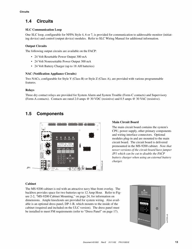
Main Circuit Board
The main circuit board contains the system's CPU, power supply, other primary components and wiring interface connectors. Optional modules plug-in and are mounted to the main circuit board. The circuit board is delivered premounted in the MS-9200 cabinet. Note that newer versions of the circuit board have jumper JP1 which can be cut to disable the FACP battery charger when using an external battery charger.
Cabinet
The MS-9200 cabinet is red with an attractive navy blue front overlay. The backbox provides space for two batteries up to 12 Amp Hour. Refer to Fig-ure 2-2, “MS-9200 Cabinet Mounting,” on page 24, for information on dimensions. Ample knockouts are provided for system wiring. Also avail-able is an optional dress panel, DP-1-B, which mounts to the inside of the cabinet (required and included on the ULC version). The dress panel must be installed to meet FM requirements (refer to “Dress Panel” on page 17).
24V UNREG 24V NONRS 24V RST BELL 2 POWER BELL 1 POWER SUPV ALARM TROUBLE PC/PRINTER TERM COMM
GN
D F
AULT
DIS
ABLE
TRAN
SFO
RM
ER 1
TRAN
SFO
RM
ER 2
- +BATTERY
RS-
232
PC/P
RIN
TER
RS-
485
TER
M. M
OD
E
TRO
UBL
E
+ - + - + - B+ A+ A- B- B+ A+ A- B- NO C NO NC C NO NC C A B B+ A+ B- A- 1 COMM 2ACS SHIELD SLC SLC
OUT+ IN+ OUT- IN-TB4
TB2
TB1
TB3
TB7
TB5
TB6
J16
J6JP3JP1CAUTIONHIGH VOLTAGE
J3TB8
J19
J17
JP4SW1
SW3
SW2
CA
UTIO
N!
HIG
H VO
LTAGE
GNDFAULT
JP1
9200
bord
.cdr
ms9
200.
cdr
Components
14 Document #51003 Rev.E 01/11/02 P/N 51003:E
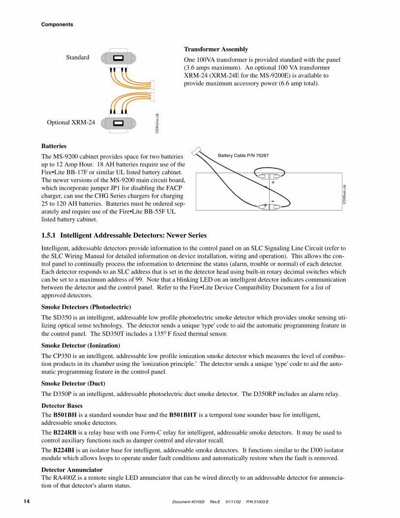
Transformer Assembly
One 100VA transformer is provided standard with the panel (3.6 amps maximum). An optional 100 VA transformer XRM-24 (XRM-24E for the MS-9200E) is available to provide maximum accessory power (6.6 amp total).
Batteries
The MS-9200 cabinet provides space for two batteries up to 12 Amp Hour. 18 AH batteries require use of the Fire•Lite BB-17F or similar UL listed battery cabinet. The newer versions of the MS-9200 main circuit board, which incorporate jumper JP1 for disabling the FACP charger, can use the CHG Series chargers for charging 25 to 120 AH batteries. Batteries must be ordered sep-arately and require use of the Fire•Lite BB-55F UL listed battery cabinet.
1.5.1 Intelligent Addressable Detectors: Newer Series
Intelligent, addressable detectors provide information to the control panel on an SLC Signaling Line Circuit (refer to the SLC Wiring Manual for detailed information on device installation, wiring and operation). This allows the con-trol panel to continually process the information to determine the status (alarm, trouble or normal) of each detector. Each detector responds to an SLC address that is set in the detector head using built-in rotary decimal switches which can be set to a maximum address of 99. Note that a blinking LED on an intelligent detector indicates communication between the detector and the control panel. Refer to the Fire•Lite Device Compatibility Document for a list of approved detectors.
Smoke Detectors (Photoelectric)
The SD350 is an intelligent, addressable low profile photoelectric smoke detector which provides smoke sensing uti-lizing optical sense technology. The detector sends a unique 'type' code to aid the automatic programming feature in the control panel. The SD350T includes a 135O F fixed thermal sensor.
Smoke Detector (Ionization)
The CP350 is an intelligent, addressable low profile ionization smoke detector which measures the level of combus-tion products in its chamber using the 'ionization principle.' The detector sends a unique 'type' code to aid the auto-matic programming feature in the control panel.
Smoke Detector (Duct)
The D350P is an intelligent, addressable photoelectric duct smoke detector. The D350RP includes an alarm relay.
Detector BasesThe B501BH is a standard sounder base and the B501BHT is a temporal tone sounder base for intelligent, addressable smoke detectors.The B224RB is a relay base with one Form-C relay for intelligent, addressable smoke detectors. It may be used to control auxiliary functions such as damper control and elevator recall.The B224BI is an isolator base for intelligent, addressable smoke detectors. It functions similar to the I300 isolator module which allows loops to operate under fault conditions and automatically restore when the fault is removed.
Detector Annunciator The RA400Z is a remote single LED annunciator that can be wired directly to an addressable detector for annuncia-tion of that detector's alarm status.
Standard
Optional XRM-24
9200
xfor
.cdr
-
-+
+
Battery Cable P/N 75287
9200
batt.
cdr

Document #51003 Rev.E 01/11/02 P/N 51003:E 15
Components
1.5.2 Intelligent Addressable Modules: Newer Series
The newer series of Control Modules and Monitor Modules provide an interface between the control panel and con-ventional notification and initiating devices. Each module can be set to respond to a maximum address of 99 with built-in rotary switches. A blinking LED on monitor modules indicates communication between the module and the control panel. Refer to the Fire•Lite Device Compatibility Document for a list of approved notification and initiating devices.
Monitor Modules
The MMF-300, MDF-300 and MMF-302 are addressable monitor modules that can be used to monitor conventional normally open contact alarm initiating devices, such as manual pull stations, 4-wire smoke detectors, heat detectors, waterflow and supervisory devices. The MDF-300 is a dual monitor module in a single package (Class B only) with each module functionally the same as the MMF-300. The MMF-302 is used primarily for two-wire smoke detectors in addition to normally open contact devices. The supervised IDCs (Initiating Device Circuit) can be wired to the module as NFPA Style B (Class B) or Style D (Class A). The modules are supplied with a thermoplastic cover for mounting to a 4-inch mounting box.
Monitor Module (miniature)
The MMF-301 is an addressable monitor module that is a miniature version of the MMF-300. It connects with wire pigtails (Style B [Class B] only), and may be mounted directly in the electrical box of the device being monitored.
Control Module
The CMF-300 is an addressable control module used to connect NACs (Notification Appliance Circuits) to power and supervise compatible UL-listed notification appliances. The NACs can be wired to the module as supervised NFPA Style Y (Class B) or Style Z (Class A) circuits. The modules are supplied with a thermoplastic cover for mounting to a 4-inch square mounting box.
Relay Module
The CRF-300 is an addressable control relay module which is functionally similar to the CMF-300 but used as a Form-C relay module
Manual Pull Station
The BG-12LX is an addressable manual pull station featuring key-lock reset. The pull station responds to an address set by the installer using the built-in rotary decimal switches on the pull station. The manual pull station includes a Fire•Lite key. The BG-12LX address module LED condition is visible through the translucent handle.
I300
The loop isolator module is an automatic switch which opens the circuit voltage to the SLC Loop branch(es) when-ever a wire-to-wire short circuit is detected on that loop. The remainder of the communications loop leading up to the I300 will continue to operate, unaffected by the short. The isolator module is bi-directional, meaning that it can detect a fault condition between the input SLC terminals or output SLC terminals. The I300 is required to meet NFPA Style 7 requirements.
1.5.3 300 Series Intelligent Addressable Devices
Fire•Lite’s legacy 300 Series Intelligent Addressable Devices are fully compatible with the MS-9200 FACP. Compatible devices include:
• SD300: Photoelectric Smoke Detector• SD300T: Photoelectric Smoke Detector with Thermal Sensor• CP300: Ionization Smoke Detector• M300: Monitor Module• M301: Miniature Monitor Module• M302: two-wire Monitor Module• C304: Control/Relay Module• BG-10LX Manual Pull Station

Optional Modules
16 Document #51003 Rev.E 01/11/02 P/N 51003:E
1.5.4 Addressable Device Accessories
E.O.L. Resistor Assemblies
The 47K End-of-Line Resistor Assembly is used to supervise the MMF-300, MDF-300, MMF-301 and CMF-300 module circuits. The 3.9K End-of-Line Resistor Assembly is used to supervise the MMF-302 module circuit. The resistors are included with each M300 and C304 module.
E.O.L. Power Supervision Relay
The UL listed End-of-Line Power Supervision Relay is used to supervise the power to 4-wire smoke detectors and notification appliances.
N-ELR Mounting Plate
The N-ELR is a single End-of-Line resistor plate which is required for use in Canada. An ELR, which is supplied with each module and fire alarm control panel, is mounted to the ELR plate. Resistors mounted to the N-ELR plate can be used for the supervision of a monitor and control module circuit.
1.6 Optional ModulesThe MS-9200 main circuit board includes option module connectors which are located on the right side of the board. Available option modules include the following:
ACM-8RF Relay Control Module
The ACM-8RF Relay Control Module contains eight high current (5 amps) Form-C relays. The module interfaces to host fire alarm control panels which employ an ACS (EIA-485) annunciator communications bus. ACM-8RF mod-ules may be connected to the EIA-485 bus up to 6,000 feet (1,800 m) away from the host control panel. Power-lim-ited, filtered, nonresettable power must be supplied by the host FACP or a UL listed power supply such as the FCPS-24F. Refer to Figure 2-14, “ACM-8RF Relay Control Module Installation,” on page 32, for wiring details.
RTM-8F Relay Module
The RTM-8F Relay/Transmitter Module plugs into connector J6 and mounts on the bottom right side of the MS-9200 main circuit board. When the module is installed, jumper JP4 must be cut in order to provide module placement supervision. The RTM-8F provides eight high current (5 amps) Form-C relays. These relays track software zones 1 through 8. The Relay/Transmitter Module also provides Municipal Box or Remote Station transmitters. An MS-9200 equipped with an RTM-8F meets NFPA 72 codes for Auxiliary and Remote Station requirements. In remote station applications, the RTM-8F can be configured to transmit alarm only or alarm and trouble signals. Dis-able switches and indicators are provided on the module. Refer to Figure 2-15, “RTM-8F Module Installation,” on page 33 and Figure 2-16, “RTM-8F Relay Transmitter Module,” on page 34, for additional information.
Printer/PC Interface - TB7
The Printer/PC Interface may be used to permanently connect a printer to the MS-9200 for the purpose of printing a history report, walktest file or program listing or smoke detector data. Printers require separate primary AC power. The printer connects to TB7 on the main circuit board. TB7 is also used to connect a computer for upload/download of programming data. Refer to the PK-9200W Off Line Programming Utility Manual for programming information. Refer to Figure 2-18, “Remote Serial Printer and Computer Connections,” on page 36, for information on connec-tions and “System Edit” on page 45, for information on programming the MS-9200 for use with a printer or PC. Switch SW3, located on the main circuit board, must be placed in the RS-232 PC/Printer position (down) when con-necting a printer or PC to TB7.
Older versions of the MS-9200 main circuit board will not have connector TB7. These boards require connection of a PIM-24 module to the serial EIA-232 port on the printer using cable P/N 75267, in order to connect a printer or PC. The module mounts to the J11 connector on the MS-9200 main circuit board. Note that the PIM-24 option cannot be used simultaneously with the DIM-485/LCD-40 option.

Document #51003 Rev.E 01/11/02 P/N 51003:E 17
Accessories
PK-9200W Kit for Local Downloading
The PK-9200W Programming Utility can be used to program an MS-9200 directly from most IBM PC/XT/AT or compatible computers, including laptops and portables, equipped with a serial port. MS-9200 program files can also be created and stored on the PC, then downloaded to the control panel. The PK-9200W Kit includes the MS-9200 Windows based Programming Utility software on four 3½" disks and the Instruction Manual P/N 50684. Older ver-sion of the MS-9200 main circuit board, which do not have connector TB7, require separate purchase of the PIM-24 Interface module.
UDACT-F Universal Digital Alarm Communicator/Transmitter
The UDACT-F transmits system status to UL listed Central Station receivers via the public switched telephone net-work. The UDACT-F is compact in size and may be mounted inside the host control panel or may mount externally in a separate cabinet. ACS (EIA-485) annunciator communications bus and filtered 24 volt connections are required. The UDACT-F transmits 198 points or 56 zones when connected to the MS-9200. The MS-9200 requires firmware P/N 73580 or greater in order to be compatible with the UDACT-F. Refer to Figure 2-11, “UDACT-F Mounting to MS-9200,” on page 30, and Figure 2-12, “External UDACT-F Mounting in ABS-8RF,” on page 31, for wiring details and “System Edit” on page 45, for information on programming the MS-9200 for use with the UDACT-F.
Annunciator/Display Interface
The LCD-40 Series Remote Fire Annunciator and other Terminal Mode annunciators connect to TB7 on the MS-9200 main circuit board. Refer to “LCD-40 Series Annunciator Wiring” on page 72, for wiring details and “Sys-tem Edit” on page 45, for information on programming the MS-9200 for use with the LCD-40.
Older versions of the MS-9200 main circuit board will not have connector TB7. These boards require connection of DIM-485 in order to connect an LCD-40 Series annunciator. The DIM-485 plugs into connector J11 located on the top right side of the MS-9200 main circuit board. Note that the DIM-485/LCD-40 cannot be used simultaneously with the PIM-24 module.
1.7 Accessories
1.7.1 Dress Panel
A dark blue dress panel, DP-1-R, is available as an option (required for Canadian installations and included with the MS-9200C). The dress panel restricts access to the system wiring while allowing access to the membrane switch panel.
Note that the MS-9200 Addressable Fire Control Panel installed with the dress panel, has received Factory Mutual (FM) approval. It is important to note that FM approval is contingent on the proper installation of the dress panel.
dp92
00.c
dr

Accessories
18 Document #51003 Rev.E 01/11/02 P/N 51003:E
1.7.2 Battery Box
BB-17F
The BB-17F battery box may be used to house two 12 AH or 18 AH batteries. The battery box mounts directly below the MS-9200 cabinet. The box is red and is provided with knockouts.
BB-55F
The BB-55F battery box may be used to house two 25 AH batteries, two 55 AH batteries or one 100 AH battery. When the CHG-120F is mounted in the BB-55F, two 25 AH or one 55 AH battery may also be housed in the box.
1.7.3 CHG-120F Battery Charger
The CHG-120F is capable of charging 25 AH to 120 AH lead-acid batteries with the newer versions of the MS-9200 main circuit board which allows disabling of the FACP battery charger. The batteries and charger can be housed in the Fire•Lite BB-55F Battery Box which can be mounted up to 20 feet away from the control panel. Note that when using the BB-55F for housing the charger and batteries, a maximum 25 AH battery can be accommodated. For larger Amp Hour batteries, use multiple BB-55Fs. Refer to the CHG-120F Manual for additional information.
WARNING: Do not apply AC power or batteries until the system is completely wired and ready for testing. Set the CHG-120F Voltage Select switch (SW1) to match the AC power source voltage (120VAC or 240 VAC). With the breaker at the main power distribution panel turned off, connect AC power wires to CHG-120F TB1 as shown below.
bb-1
7f.c
dr
bb-5
5f.c
dr
!
Document #51003 Rev.E 01/11/02 P/N 51003:E 19
Accessories
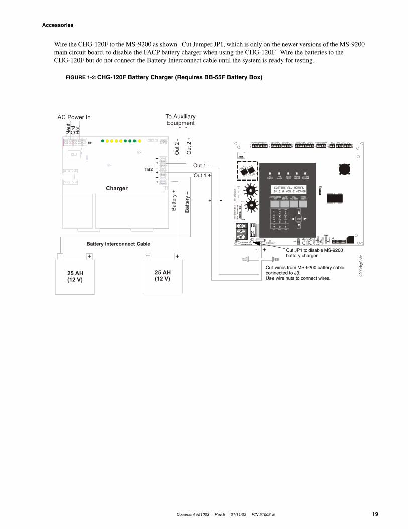
Wire the CHG-120F to the MS-9200 as shown. Cut Jumper JP1, which is only on the newer versions of the MS-9200 main circuit board, to disable the FACP battery charger when using the CHG-120F. Wire the batteries to the CHG-120F but do not connect the Battery Interconnect cable until the system is ready for testing.
24V UNREG 24V NONRS 24V RST BELL 2 POWER BELL 1 POWER SUPV ALARM TROUBLE PC/PRINTER TERM COMM
GN
D F
AULT
DIS
ABLE
TRAN
SFO
RM
ER 1
TRAN
SFO
RM
ER 2
- +BATTERY
RS-
232
PC/P
RIN
TER
RS
-485
TER
M. M
OD
E
TRO
UBL
E
+ - + - + - B+ A+ A- B- B+ A+ A- B- NO C NO NC C NO NC C A B B+ A+ B- A- 1 COMM 2ACS SHIELD SLC SLC
OUT+ IN+ OUT- IN-TB4
TB2
TB1
TB3
TB7
TB5
TB6
J16
J6JP3JP1
CAUTIONHIGH VOLTAGE
J3TB8
J19
J17
JP4SW1
SW3
SW2
CA
UTIO
N!
HIG
H VOLTA
GE
GNDFAULT
- +
Batte
ry –
25 AH(12 V)
25 AH(12 V)
– + – +
TB2
TB1
–+–+–+
Batte
ry +
Battery Interconnect Cable
Charger
To AuxiliaryEquipment
AC Power In
Neu
tG
rdH
ot
Out
2 -
Out 1 +
Out 1 -
Out
2 +
FIGURE 1-2:CHG-120F Battery Charger (Requires BB-55F Battery Box)
Cut wires from MS-9200 battery cable connected to J3.Use wire nuts to connect wires.
Cut JP1 to disable MS-9200 battery charger.
- +
9200
chgf
.cdr

Accessories
20 Document #51003 Rev.E 01/11/02 P/N 51003:E
1.7.4 Annunciators
LED Zone Type Annunciators
The ACS Series Annunciators remotely display system status. The ACM/AEM-16ATF annunciators display zone alarm and trouble status. In addition, they provide remote Acknowledge, Silence, Reset and Drill functions. The ACM/AEM-32AF annunciators display zone alarm status only and provide no remote system switch functions. For more detailed information, refer to the appropriate ACS Annunciator manual. Refer to “ACS and LDM Series Wir-ing” on page 73, for detailed wiring requirements and “System Edit” on page 45, for information on programming the MS-9200 for annunciator use.
ACM-16ATF
The Annunciator Control Mod-ule-16ATF contains 16 red alarm and 16 yellow trouble LEDs, a System Trouble LED, an On Line/Power LED and a local piezo sounder with switches for MS-9200 Acknowledge, Silence, Reset and Drill. The ACM-16ATF has rotary address switches and will accept up to three AEM-16ATF Expanders.
AEM-16ATF
The Annunciator Expander Module-16ATF connects to the AFM-16ATX and adds 16 sets of red alarm LEDs and yellow trouble LEDs. Three AEM-16ATFs may be added to an AFM-16ATX.
AFM-16ATF
The Annunciator Fixed Module-16ATF contains 16 red alarm and 16 yellow trouble LEDs, a System Trouble LED, an On Line/Power LED and a local piezo sounder with switches for MS-9200 Acknowledge, Silence, Reset and Drill. The AFM-16ATF is fixed at address '1' and communication is via the ACS (EIA-485) data line.
ACM-32AF
The Annunciator Control Module-32AF contains 32 red alarm LEDs, a System Trouble LED, an On Line/Power LED and a local piezo sounder with a local Silence/Acknowledge switch. The ACM-32AF has rotary address switches and will accept one AEM-32AF Expander.
AEM-32AF
The Annunciator Expander Mod-ule-32AF connects to the AFM-32AX and adds 32 red alarm LEDs. The AEM-32AF is identi-cal in frontal appearance to the AFM-32AX. Only one expander module is allowed.
AFM-16AF
The Annunciator Fixed Module-16AF has 16 red alarm LEDs. Multiple annunciators may be used by setting all annunciators to Receive Only, except the last AFM-16AF in line. Each annun-ciator's address is internally fixed at '1', and communication is via the ACS (EIA-485) data line. The Local Silence/Acknowledge switch functions as local lamp test and silence for annunciator piezo. LEDs include On Line and Sys-tem Trouble indicators.
AFM-32AF
The AFM-32AF is similar to the AFM-16AF except it has 32 red alarm LEDs for annunciating up to 32 points.

Document #51003 Rev.E 01/11/02 P/N 51003:E 21
Accessories
LCD-40 Series Remote Fire Annunciators
The LCD-40 Series, consisting of the LCD-40 and LCD-40L, are com-pact, attractive, 40-character backlit LCD fire annunciators that are capable of displaying English-language text. They mimic the display on the MS-9200 main control circuit board and will annunciate device type, point alarm, trouble or supervisory condition, zone assignment plus any custom alpha labels programmed into the control panel. They also provide system status LEDs to display power, alarm, trouble and supervisory conditions. Additionally, the LCD-40 is capable of per-forming critical system functions such as acknowledge, silence, reset and drill, remotely from the host control panel.
Communication between the control panel and the LCD-40 Series is accomplished over a serial interface employing the EIA-485 communication standard. Up to 32 LCD-40 Series Annunciators may be connected to the TERM (EIA-485) circuit. The annunciators may be powered from the host FACP or a remote UL listed filtered power sup-ply such as the Fire•Lite FCPS-24F. Refer to “LCD-40 Series Annunciator Wiring” on page 72, for detailed wiring requirements and “System Edit” on page 45, for information on programming the MS-9200 for annunciator use.
Note: If software with either the Part Number 73750 or 73829 is installed in the MS-9200, the LCD-40 Series must have software with a Part Number of 73779 or 73879 to operate with the FACP. If software with a Part Number of #M9200V20 or higher is installed in the MS-9200, the LCD-40 Series must have software with a Part Number of #LCD40V20 or higher to operate with the FACP.
LDM Series Lamp Driver Modules - Graphic Annunciator
The LDM Series Lamp Driver Modules, which consist of the LDM-32F master and LDM-E32F expander modules, are used to provide an interface to a custom graphic LED annunciator. The master module provides power and con-trol for a maximum of three expander modules. The LDM-32F and LDM-E32F have output connectors which are used to drive lamps or LEDs and input connectors which are used for remote switch functions. Refer to the LDM Series Lamp Drive Modules Manual for a complete description. See “ACS and LDM Series Wiring” on page 73, for wiring requirements and “System Edit” on page 45, for details on programming the MS-9200 for annunciator use.
The LDM-32F
The Lamp Drive Module LDM-32F has 32 alarm lamp/LED driver outputs which sink cur-rent to system common (-) on activation. A single positive (+) voltage is required to supply total operating power for all lamps or LEDs when all drivers are activated. The LDM-32F provides a separate driver for system trouble and inputs for a local lamp test switch. A maximum of 16 external control switches may be wired to the LDM-32F. DIP switch SW3 is used to enable or disable the onboard piezo sounder, enable remote switch functions, select a flashing LED function for new alarms and troubles and other functions. Switch SW4 is used to configure the module to annunciate 32 alarms or 16 alarms and 16 troubles. A green On Line LED flashes to indicate ongoing communications with the host FACP. One LDM-32F supports up to three LDM-E32F modules. The LDM-32F is supplied with four standoffs and screws for mounting to a CHS-4L chassis or custom backbox.
The LDM-E32F
Each LDM-E32F expander module provides 32 additional lamp/LED driver outputs from J5, J6, J7 and J8. The expander module has a slide switch, SW4, for selecting alarm only or alarm and trouble annunciation and an input for a local lamp test switch. In alarm only mode, use only one LDM-32F and one LDM-E32F for a maximum of 56 alarm indicators and 8 system status indicators. In alarm/trouble mode, use one LDM-32F and three LDM-E32Fs for a maximum of 56 alarm indicators, 56 trouble indicators, 16 status indicators and 64 optional control switch inputs. Multiple sets of LDM-32Fs with LDM-E32F expanders increase the system annunciation capabilities beyond 56 zones or points. This is possible by various settings of address switches SW1 and SW2 on the LDM-32F (refer to Appendices). Each LDM-E32F is supplied with a 26-conductor expander ribbon cable, four standoffs and screws.
®
Ack Silence ResetDrillHold 2 sec.
FIRE ALARM ANNUNCIATOR
lcd4
0.cd
r
J10
J9
J2
LAMPPOWER
SWITCHMATRIX
KEYSWITCH
ON LINE
J11
J5 J6 J7 J8
J4
J1
SW1
SW2
SW3
SW4
TB2
TB1
2
2
3
3
4
45671
1
J6J5
J4
J1
SW4
SWITCHMATRIX
OUTPUTS J7 J8
J10
J2
Accessories
22 Document #51003 Rev.E 01/11/02 P/N 51003:E
1.7.5 FCPS-24F/E Remote Field Charger Power Supply for System Power Expansion
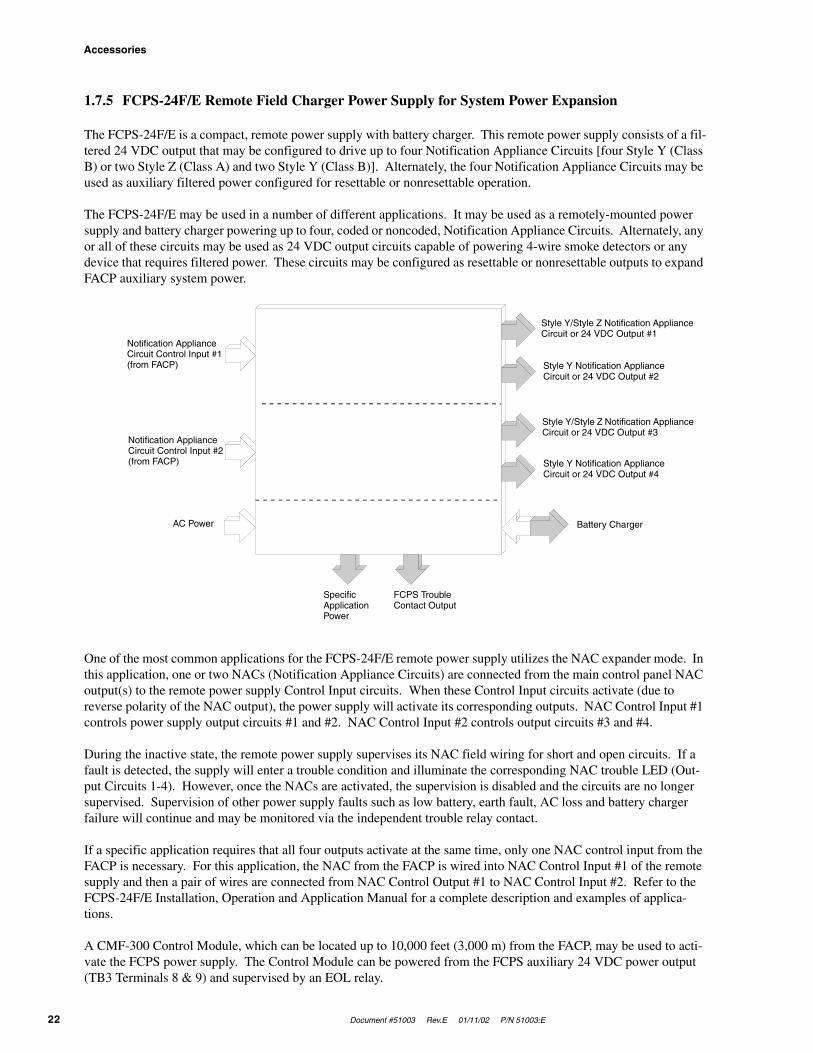
The FCPS-24F/E is a compact, remote power supply with battery charger. This remote power supply consists of a fil-tered 24 VDC output that may be configured to drive up to four Notification Appliance Circuits [four Style Y (Class B) or two Style Z (Class A) and two Style Y (Class B)]. Alternately, the four Notification Appliance Circuits may be used as auxiliary filtered power configured for resettable or nonresettable operation.
The FCPS-24F/E may be used in a number of different applications. It may be used as a remotely-mounted power supply and battery charger powering up to four, coded or noncoded, Notification Appliance Circuits. Alternately, any or all of these circuits may be used as 24 VDC output circuits capable of powering 4-wire smoke detectors or any device that requires filtered power. These circuits may be configured as resettable or nonresettable outputs to expand FACP auxiliary system power.
One of the most common applications for the FCPS-24F/E remote power supply utilizes the NAC expander mode. In this application, one or two NACs (Notification Appliance Circuits) are connected from the main control panel NAC output(s) to the remote power supply Control Input circuits. When these Control Input circuits activate (due to reverse polarity of the NAC output), the power supply will activate its corresponding outputs. NAC Control Input #1 controls power supply output circuits #1 and #2. NAC Control Input #2 controls output circuits #3 and #4.
During the inactive state, the remote power supply supervises its NAC field wiring for short and open circuits. If a fault is detected, the supply will enter a trouble condition and illuminate the corresponding NAC trouble LED (Out-put Circuits 1-4). However, once the NACs are activated, the supervision is disabled and the circuits are no longer supervised. Supervision of other power supply faults such as low battery, earth fault, AC loss and battery charger failure will continue and may be monitored via the independent trouble relay contact.
If a specific application requires that all four outputs activate at the same time, only one NAC control input from the FACP is necessary. For this application, the NAC from the FACP is wired into NAC Control Input #1 of the remote supply and then a pair of wires are connected from NAC Control Output #1 to NAC Control Input #2. Refer to the FCPS-24F/E Installation, Operation and Application Manual for a complete description and examples of applica-tions.
A CMF-300 Control Module, which can be located up to 10,000 feet (3,000 m) from the FACP, may be used to acti-vate the FCPS power supply. The Control Module can be powered from the FCPS auxiliary 24 VDC power output (TB3 Terminals 8 & 9) and supervised by an EOL relay.
SpecificApplicationPower
FCPS Trouble Contact Output
AC Power
Notification Appliance Circuit Control Input #2 (from FACP)
Notification Appliance Circuit Control Input #1 (from FACP)
Style Y/Style Z Notification Appliance Circuit or 24 VDC Output #1
Style Y Notification Appliance Circuit or 24 VDC Output #2
Style Y/Style Z Notification Appliance Circuit or 24 VDC Output #3
Style Y Notification Appliance Circuit or 24 VDC Output #4
Battery Charger
Document #51003 Rev.E 01/11/02 P/N 51003:E 23
Installation
CHAPTER 2 Installation
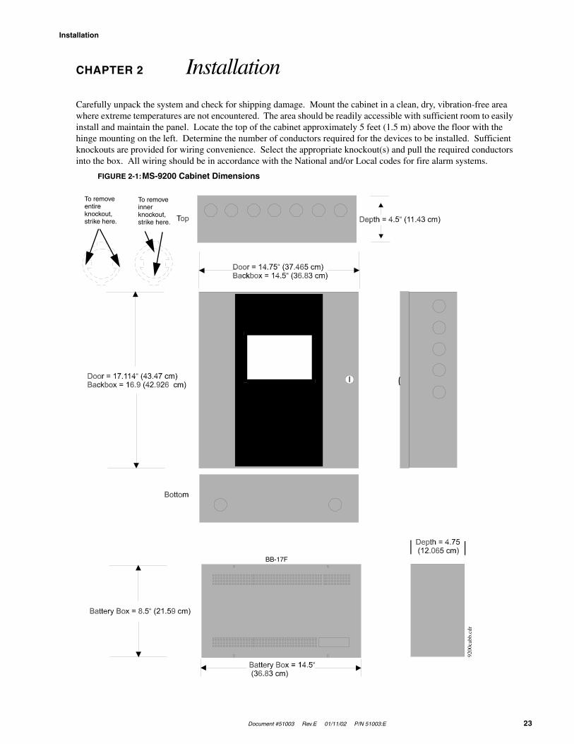
Carefully unpack the system and check for shipping damage. Mount the cabinet in a clean, dry, vibration-free area where extreme temperatures are not encountered. The area should be readily accessible with sufficient room to easily install and maintain the panel. Locate the top of the cabinet approximately 5 feet (1.5 m) above the floor with the hinge mounting on the left. Determine the number of conductors required for the devices to be installed. Sufficient knockouts are provided for wiring convenience. Select the appropriate knockout(s) and pull the required conductors into the box. All wiring should be in accordance with the National and/or Local codes for fire alarm systems.
FIGURE 2-1:MS-9200 Cabinet Dimensions
To remove entire knockout, strike here.
To remove inner knockout, strike here.
BB-17F
9200
cabb
.cdr
Backbox Mounting
24 Document #51003 Rev.E 01/11/02 P/N 51003:E
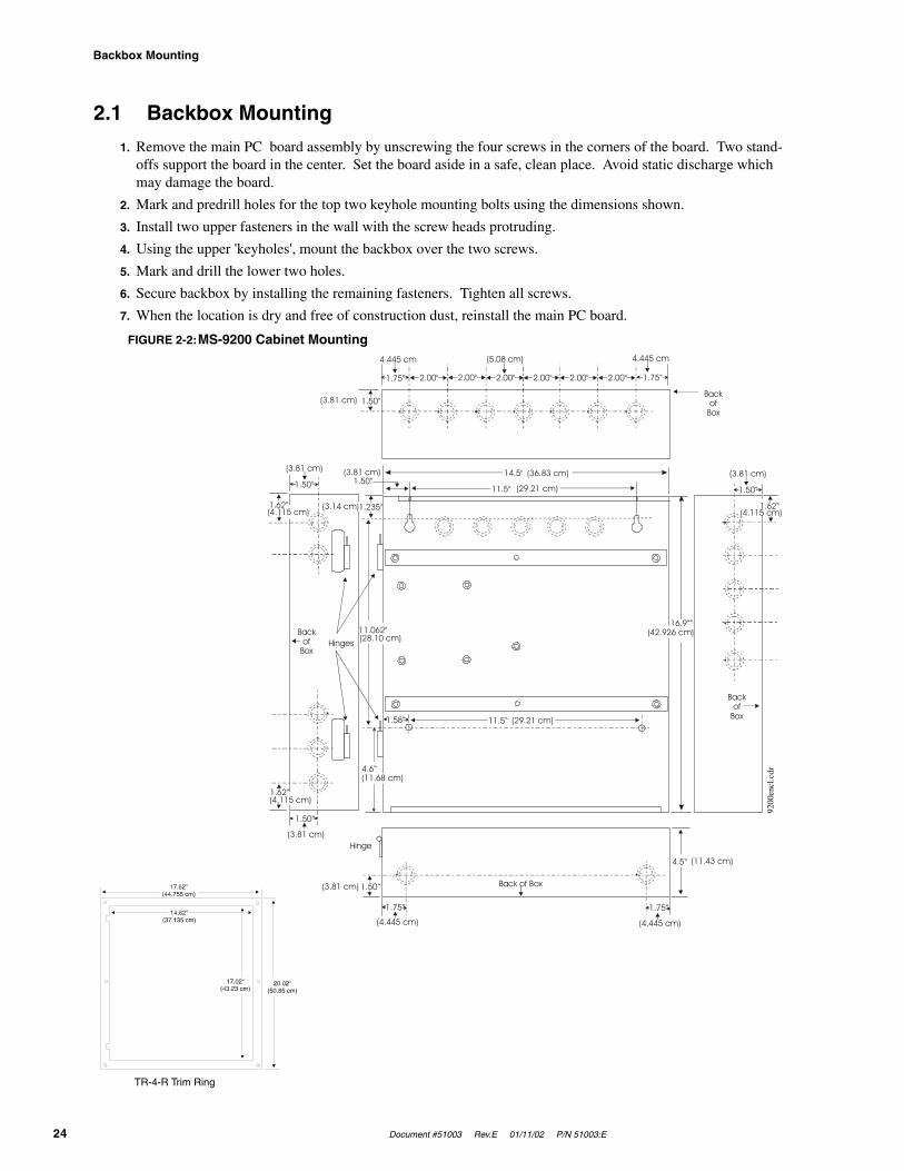
2.1 Backbox Mounting
1. Remove the main PC board assembly by unscrewing the four screws in the corners of the board. Two stand-offs support the board in the center. Set the board aside in a safe, clean place. Avoid static discharge which may damage the board.
2. Mark and predrill holes for the top two keyhole mounting bolts using the dimensions shown.
3. Install two upper fasteners in the wall with the screw heads protruding.
4. Using the upper 'keyholes', mount the backbox over the two screws.
5. Mark and drill the lower two holes.
6. Secure backbox by installing the remaining fasteners. Tighten all screws.
7. When the location is dry and free of construction dust, reinstall the main PC board.
14.5"
16.9“”
11.5"1.50“
1.235"
1.50“
1.50“
1.62“
1.62“
Hinges
Hinge
Backof
Box
Back of Box
2.00" 2.00" 2.00" 2.00" 2.00" 2.00"1.75“
4.445 cm 4.445 cm
1.50“(3.81 cm)
(3.81 cm) (3.81 cm)
(3.81 cm)
(3.81 cm)
(4.445 cm) (4.445 cm)
(11.43 cm)
(3.81 cm)(36.83 cm)
(29.21 cm)
(5.08 cm)
1.75“
1.50“
4.5“
1.50“
4.6“
1.58“ 11.5“
1.75“ 1.75“
Backof
Box
Backof
Box
(4.115 cm)(3.14 cm)
(4.115 cm)
(42.926 cm)
(11.68 cm)
(29.21 cm)
(4.115 cm)
(28.10 cm)11.062"
1.62“
FIGURE 2-2:MS-9200 Cabinet Mounting
TR-4-R Trim Ring
9200
encl
.cdr
Document #51003 Rev.E 01/11/02 P/N 51003:E 25
Power
2.2 Power
WARNING: Several different sources of power can be connected to this panel. Disconnect all sources of power before servicing. The panel and associated equipment may be damaged by removing and/or inserting cards, modules or interconnecting cables while this unit is energized.
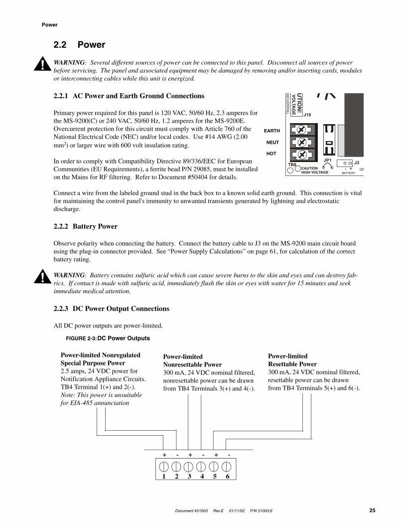
2.2.1 AC Power and Earth Ground Connections
Primary power required for this panel is 120 VAC, 50/60 Hz, 2.3 amperes for the MS-9200(C) or 240 VAC, 50/60 Hz, 1.2 amperes for the MS-9200E. Overcurrent protection for this circuit must comply with Article 760 of the National Electrical Code (NEC) and/or local codes. Use #14 AWG (2.00 mm2) or larger wire with 600 volt insulation rating.
In order to comply with Compatibility Directive 89/336/EEC for European Communities (EU Requirements), a ferrite bead P/N 29085, must be installed on the Mains for RF filtering. Refer to Document #50404 for details.
Connect a wire from the labeled ground stud in the back box to a known solid earth ground. This connection is vital for maintaining the control panel's immunity to unwanted transients generated by lightning and electrostatic discharge.
2.2.2 Battery Power
Observe polarity when connecting the battery. Connect the battery cable to J3 on the MS-9200 main circuit board using the plug-in connector provided. See “Power Supply Calculations” on page 61, for calculation of the correct battery rating.
WARNING: Battery contains sulfuric acid which can cause severe burns to the skin and eyes and can destroy fab-rics. If contact is made with sulfuric acid, immediately flush the skin or eyes with water for 15 minutes and seek immediate medical attention.
2.2.3 DC Power Output Connections
All DC power outputs are power-limited.
!
TRAN
SFO
RM
- +BATTERY
JP1
CAUTIONHIGH VOLTAGE
J3TB8
J19
UTIO
N!
VOLTA
GE
GN
EARTH
NEUT
HOT
!
Power-limited Nonregulated Special Purpose Power2.5 amps, 24 VDC power for Notification Appliance Circuits. TB4 Terminal 1(+) and 2(-). Note: This power is unsuitable for EIA-485 annunciation
1 2 3 4 5 6
+ - + - + -
FIGURE 2-3:DC Power Outputs
Power-limited Nonresettable Power300 mA, 24 VDC nominal filtered, nonresettable power can be drawn from TB4 Terminals 3(+) and 4(-).
Power-limited Resettable Power300 mA, 24 VDC nominal filtered, resettable power can be drawn from TB4 Terminals 5(+) and 6(-).
Standard Relays
26 Document #51003 Rev.E 01/11/02 P/N 51003:E
2.3 Standard Relays
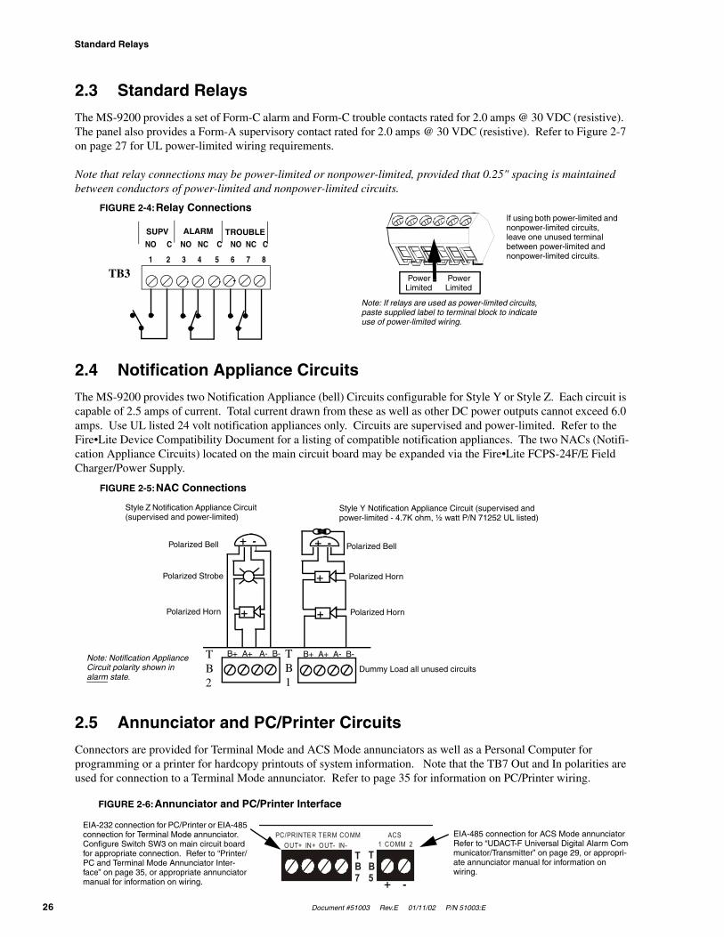
The MS-9200 provides a set of Form-C alarm and Form-C trouble contacts rated for 2.0 amps @ 30 VDC (resistive). The panel also provides a Form-A supervisory contact rated for 2.0 amps @ 30 VDC (resistive). Refer to Figure 2-7 on page 27 for UL power-limited wiring requirements.
Note that relay connections may be power-limited or nonpower-limited, provided that 0.25" spacing is maintained between conductors of power-limited and nonpower-limited circuits.
2.4 Notification Appliance Circuits
The MS-9200 provides two Notification Appliance (bell) Circuits configurable for Style Y or Style Z. Each circuit is capable of 2.5 amps of current. Total current drawn from these as well as other DC power outputs cannot exceed 6.0 amps. Use UL listed 24 volt notification appliances only. Circuits are supervised and power-limited. Refer to the Fire•Lite Device Compatibility Document for a listing of compatible notification appliances. The two NACs (Notifi-cation Appliance Circuits) located on the main circuit board may be expanded via the Fire•Lite FCPS-24F/E Field Charger/Power Supply.
2.5 Annunciator and PC/Printer Circuits
Connectors are provided for Terminal Mode and ACS Mode annunciators as well as a Personal Computer for programming or a printer for hardcopy printouts of system information. Note that the TB7 Out and In polarities are used for connection to a Terminal Mode annunciator. Refer to page 35 for information on PC/Printer wiring.
FIGURE 2-4:Relay Connections
1 2 3 4 5 6 7 8
TB3
SUPV ALARM TROUBLENO C NO NC C NO NC C
If using both power-limited and nonpower-limited circuits, leave one unused terminal between power-limited and nonpower-limited circuits.
Note: If relays are used as power-limited circuits, paste supplied label to terminal block to indicate use of power-limited wiring.
PowerLimited
PowerLimited
B+ A+ A- B- B+ A+ A- B-
Dummy Load all unused circuits
+
+ -
+
+ -
+
Polarized Horn
Polarized Horn
Polarized Horn
Polarized Strobe
Polarized Bell Polarized Bell
TB1
TB2
Note: Notification Appliance Circuit polarity shown in alarm state.
FIGURE 2-5:NAC Connections
Style Z Notification Appliance Circuit (supervised and power-limited)
Style Y Notification Appliance Circuit (supervised and power-limited - 4.7K ohm, ½ watt P/N 71252 UL listed)
PC/PRINTER TERM COMM1 COMM 2
ACSOUT+ IN+ OUT- IN-
TB7
TB5 + -
EIA-485 connection for ACS Mode annunciatorRefer to “UDACT-F Universal Digital Alarm Com-municator/Transmitter” on page 29, or appropri-ate annunciator manual for information on wiring.
EIA-232 connection for PC/Printer or EIA-485 connection for Terminal Mode annunciator. Configure Switch SW3 on main circuit board for appropriate connection. Refer to “Printer/PC and Terminal Mode Annunciator Inter-face” on page 35, or appropriate annunciator manual for information on wiring.
FIGURE 2-6:Annunciator and PC/Printer Interface

Document #51003 Rev.E 01/11/02 P/N 51003:E 27
UL Power-limited Wiring Requirements
2.6 UL Power-limited Wiring Requirements
Power-limited and nonpower-limited circuit wiring must remain separated in the cabinet. All power-limited circuit wiring must remain at least 0.25" (6.35 mm) away from any nonpower-limited circuit wiring. Furthermore, all power-limited circuit wiring and nonpower-limited circuit wiring must enter and exit the cabinet through different knockouts and/or conduits. A typical wiring diagram for the MS-9200 is shown in Figure 2-7.
24V UNREG 24V NONRS 24V RST BELL 2 POWER BELL 1 POWER SUPV ALARM TROUBLE PC/PRINTER TERM COMM
GN
D F
AU
LTDI
SAB
LE
TRAN
SFO
RM
ER 1
TRAN
SFO
RM
ER 2
- +BATTERY
RS
-232
PC/P
RIN
TER
RS
-485
TERM
. MO
DE
TRO
UB
LE
+ - + - + - B+ A+ A- B- B+ A+ A- B- NO C NO NC C NO NC C A B B+ A+ B- A- 1 COMM 2ACS SHIELD SLC SLC
OUT+ IN+ OUT- IN-TB4
TB2
TB1
TB3
TB7
TB5
TB6
J16
J6JP3JP1
CAUTIONHIGH VOLTAGE
J3TB8
J19
J17
JP4SW1
SW3
SW2
CA
UTIO
N!
HIGH VO
LTAGE
GNDFAULT
C
C
C
C
C
C
C
C
NC
NC
NC
NC
NC
NC
NC
NC
NO
NO
NO
NO
NO
NO
NO
NO
FIGURE 2-7:Typical UL Power-limited Wiring Requirements
Power-limited Circuits Power-limited CircuitsNonpower-limited Circuits
Power-limited Circuits
Nonpower-limited Circuits
AC Power
Note: Output is nonpower-limited only if programmed as municipal box output.
Power-limited Circuit
Nonpower-limited Circuit
Nonpower-limited Circuit
No connection
Power-limited Circuit
Power-limited Circuit
Power-limited Circuit
Nonpower-limited Circuit
Nonpower-limited Circuit
Nonpower-limited Circuit
RTM-8F UL Power-limited Wiring Requirements
Nonpower-limited and power-limited wiring must have a minimum distance of 0.25" wire-to-wire. If this module is used to drive nonpower-limited and power-limited circuits, follow the instructions below:
1. Skip a set of dry contacts to maintain the 0.25" required space between power-limited and nonpower-limited circuits.
2. If this module is needed to drive power-limited and nonpower-limited relays that are next to each other, make no connection to the Normally Open contact which sepa-rates the two groups of relays. Refer to the typical wiring diagram to the right.
Refer to Figure 2-16, “RTM-8F Relay Transmitter Module,” on page 34, for additional information on the RTM-8F.
Grounding Stud
9200
pwrl
.cdr
Wiring the Signaling Line Circuit
28 Document #51003 Rev.E 01/11/02 P/N 51003:E
2.7 Wiring the Signaling Line Circuit
The MS-9200 communicates with addressable initiating, monitor and control devices through a Signaling Line Cir-cuit (SLC) loop, which can be wired to meet NFPA requirements for Style 4, Style 6 or Style 7.
2.7.1 Device Capacity
The capacity of the MS-9200 includes up to 99 addressable detectors and an additional combination of up to 99 addressable pull stations, control modules and monitor modules. Note: Refer to the installation drawings supplied with each loop device for rating and specifications.
2.7.2 Surge Suppression
Surge protection for the SLC may be provided by using one of the UL listed compatible surge suppressors listed in the Fire•Lite Device Compatibility Document. The SLC is allowed to leave the building only with the use of a UL listed surge suppressor.
2.7.3 Installation
For information on installing devices on the SLC, refer to the SLC Wiring Manual.
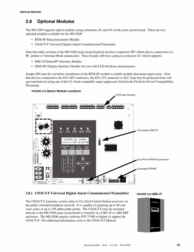
Document #51003 Rev.E 01/11/02 P/N 51003:E 29
Optional Modules
2.8 Optional Modules
The MS-9200 supports option modules using connectors J6, and J16 on the main circuit board. There are two optional modules available for the MS-9200:
• RTM-8F Relay/transmitter Module
• UDACT-F Universal Digital Alarm Communicator/Transmitter
Note that older versions of the MS-9200 main circuit board do not have connector TB7 which allows connection of a PC, printer or Terminal Mode annunciator. These boards will have a plug-in connector J11 which supports:
• PIM-24 Printer/PC Interface Module
• DIM-485 Display Interface Module (for use with LCD-40 Series annunciators)
Jumper JP4 must be cut before installation of the RTM-8F module to enable module placement supervision. Note that devices connected to the EIA-485 connectors, the EIA-232 connector or SLC loop may be protected from volt-age transients by using one of the UL listed compatible surge suppressors listed in the Fire•Lite Device Compatibility Document.
2.8.1 UDACT-F Universal Digital Alarm Communicator/Transmitter
The UDACT-F transmits system status to UL listed Central Station receivers via the public switched telephone network. It is capable of reporting up to 56 soft-ware zones or up to 198 addressable points. The UDACT-F may be mounted directly to the MS-9200 main circuit board or remotely in a UBS-1F or ABS-8RF enclosure. The MS-9200 requires software P/N 73580 or higher to support the UDACT-F. For additional information, refer to the UDACT-F Manual.
24V UNREG 24V NONRS 24V RST BELL 2 POWER BELL 1 POWER SUPV ALARM TROUBLE PC/PRINTER TERM COMM
GN
D F
AULT
DIS
ABLE
TRAN
SFO
RM
ER 1
TRAN
SFO
RM
ER 2
- +BATTERY
RS-
232
PC/P
RIN
TER
RS-
485
TER
M. M
OD
E
TRO
UBL
E+ - + - + - B+ A+ A- B- B+ A+ A- B- NO C NO NC C NO NC C A B B+ A+ B- A- 1 COMM 2
ACS SHIELD SLC SLCOUT+ IN+ OUT- IN-
TB4
TB2
TB1
TB3
TB7
TB5
TB6
J16
J6JP3JP1
CAUTIONHIGH VOLTAGE
J3TB8
J19
J17
JP4SW1
SW3
SW2
CA
UTIO
N!
HIG
H VO
LTAG
E
GNDFAULT
FIGURE 2-8:Option Module LocationsPC/Printer Interface
J16 accepts UDACT-F
Cut JP4 for RTM-8F supervision
J6 accepts RTM-8F
9200
bord
.cdr
FIGURE 2-9:UBS-1F
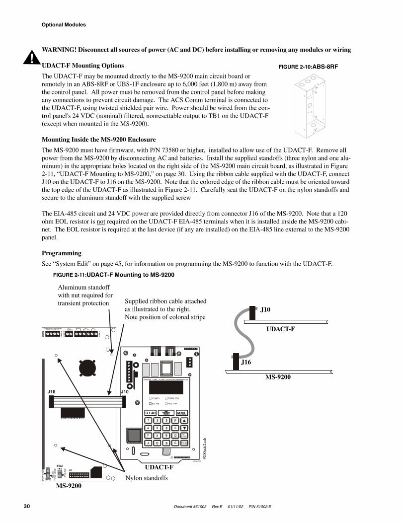
Optional Modules
30 Document #51003 Rev.E 01/11/02 P/N 51003:E
WARNING! Disconnect all sources of power (AC and DC) before installing or removing any modules or wiring
UDACT-F Mounting Options
The UDACT-F may be mounted directly to the MS-9200 main circuit board or remotely in an ABS-8RF or UBS-1F enclosure up to 6,000 feet (1,800 m) away from the control panel. All power must be removed from the control panel before making any connections to prevent circuit damage. The ACS Comm terminal is connected to the UDACT-F, using twisted shielded pair wire. Power should be wired from the con-trol panel's 24 VDC (nominal) filtered, nonresettable output to TB1 on the UDACT-F (except when mounted in the MS-9200).
Mounting Inside the MS-9200 Enclosure
The MS-9200 must have firmware, with P/N 73580 or higher, installed to allow use of the UDACT-F. Remove all power from the MS-9200 by disconnecting AC and batteries. Install the supplied standoffs (three nylon and one alu-minum) in the appropriate holes located on the right side of the MS-9200 main circuit board, as illustrated in Figure 2-11, “UDACT-F Mounting to MS-9200,” on page 30. Using the ribbon cable supplied with the UDACT-F, connect J10 on the UDACT-F to J16 on the MS-9200. Note that the colored edge of the ribbon cable must be oriented toward the top edge of the UDACT-F as illustrated in Figure 2-11. Carefully seat the UDACT-F on the nylon standoffs and secure to the aluminum standoff with the supplied screw
The EIA-485 circuit and 24 VDC power are provided directly from connector J16 of the MS-9200. Note that a 120 ohm EOL resistor is not required on the UDACT-F EIA-485 terminals when it is installed inside the MS-9200 cabi-net. The EOL resistor is required at the last device (if any are installed) on the EIA-485 line external to the MS-9200 panel.
Programming
See “System Edit” on page 45, for information on programming the MS-9200 to function with the UDACT-F.
!FIGURE 2-10:ABS-8RF
J5udactno.CDR
PC/PRINTER TERM COMM
PC/P
RIN
TER
RS-
485
TER
M. M
OD
E
TRO
UBL
E
A B B+ A+ B- A- 1 COMM 2ACS SHIELD SLC SLC
OUT+ IN+ OUT- IN-TB3
TB7
TB5
TB6
J6
SW3
SW2
J16 J10
FIGURE 2-11:UDACT-F Mounting to MS-9200
Aluminum standoff with nut required for transient protection
Nylon standoffs
UDACT-F
MS-9200
Supplied ribbon cable attached as illustrated to the right. Note position of colored stripe
UDACT-F
MS-9200
J10
J16
9200
udc2
.cdr

Document #51003 Rev.E 01/11/02 P/N 51003:E 31
Optional Modules
Notes:
1. This arrangement allows use of the UDACT-F simultaneously with the RTM-8F module.2. Ferrite cores (P/N FBD-1) are recommended for all applications.3. Recommended wire is 12 AWG to 18 AWG (0.75 to 3.25 mm2) twisted, shielded pair.4. If shielded wire is used, connect only one end of the shield:
✓ shield may be connected to cabinet (earth ground) at fire alarm panel, or✓ shield may be connected to TB1 Terminal 5 (shield) at UDACT-F. Note that the shield end that is not
connected should be insulated to prevent accidental grounding. Do not connect both ends of shield under any circumstances since a ground fault may result.
5. Conduit is recommended for external wire runs (consult local building codes).6. Connect ground strap (supplied with ABS-8RF enclosure) from Earth Ground terminal on the UDACT-F to a
solid building earth ground. Conduit alone will not provide a reliable earth ground.7. UDACT-F may be located up to 6,000 feet (1,800 m) away from the host control panel.8. Refer to “Specifications” on page 11 for power requirements.9. UDACT-F TB1 Terminals 6 and 7 are for future use. Make no connections to these terminals.
FIGURE 2-12:External UDACT-F Mounting in ABS-8RF
Supervised and Power-limited ACS (EIA-485) and power connections.Surge protection can be provided by using one of the UL listed compatible surge suppressors listed in the Fire•Lite Device Compatibility Document.
+24 VDCNonresettablePower (TB4)
Ferrite CoresP/N FBD-1
To Phone Lines(supervised)
Solid Earth Ground Connection
Future UseShield
MS-9200 Cabinet
Install 120 ohm EOL resistor (P/N 71244) on TB1 Terminals 3 & 4, if last or only device on EIA-485 line.
UDACT-F in ABS-8RF(shown with cover removed)
MS-9200
RTM-8F
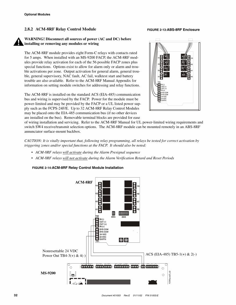
Optional Modules
32 Document #51003 Rev.E 01/11/02 P/N 51003:E
2.8.2 ACM-8RF Relay Control Module
WARNING! Disconnect all sources of power (AC and DC) before installing or removing any modules or wiring
The ACM-8RF module provides eight Form-C relays with contacts rated for 5 amps. When installed with an MS-9200 FACP, the ACM-8RF mod-ules provide relay activation for each of the 56 possible FACP zones plus special functions. Options exist to allow for alarm only or alarm and trou-ble activations per zone. Output activation for general alarm, general trou-ble, general supervisory, NAC fault, AC fail, walktest start and battery trouble are also available. Refer to the ACM-8RF Manual Appendix for information on setting module switches for addressing and relay functions.
The ACM-8RF is installed on the standard ACS (EIA-485) communication bus and wiring is supervised by the FACP. Power for the module must be power-limited and may be provided by the FACP or a UL listed power sup-ply such as the FCPS-24F/E. Up to 32 ACM-8RF Relay Control Modules may be placed onto the EIA-485 communication bus (if no other devices are installed on the bus). Removable terminal blocks are provided for ease of wiring installation and servicing. Refer to the ACM-8RF Manual for UL power-limited wiring requirements and switch SW4 receive/transmit selection options. The ACM-8RF module can be mounted remotely in an ABS-8RF annunciator surface-mount backbox.
CAUTION: It is vitally important that, following relay programming, all relays be tested for correct activation by triggering zones and/or special functions at the FACP. It should also be noted:
• ACM-8RF relays will activate during the Alarm Presignal sequence
• ACM-8RF relays will not activate during the Alarm Verification Retard and Reset Periods
FIGURE 2-13:ABS-8RF Enclosure
!
24V UNREG 24V NONRS 24V RST BELL 2 POWER BELL 1 POWER SUPV ALARM TROUBLE PC/PRINTER TERM COMM+ - + - + - B+ A+ A- B- B+ A+ A- B- NO C NO NC C NO NC C A B B+ A+ B- A- 1 COMM 2ACS SHIELD SLC SLC
OUT+ IN+ OUT- IN-TB4
TB2
TB1
TB3
TB7
TB5
TB6
1 2 3 4 5 6 7 81 2
FIGURE 2-14:ACM-8RF Relay Control Module Installation
ACM-8RF
MS-9200
ACS (EIA-485) TB5-1(+) & 2(-)Nonresettable 24 VDC Power Out TB4-3(+) & 4(-)
9200
acm
8.cd
r
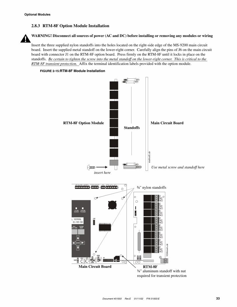
Document #51003 Rev.E 01/11/02 P/N 51003:E 33
Optional Modules
2.8.3 RTM-8F Option Module Installation
WARNING! Disconnect all sources of power (AC and DC) before installing or removing any modules or wiring
Insert the three supplied nylon standoffs into the holes located on the right-side edge of the MS-9200 main circuit board. Insert the supplied metal standoff on the lower-right corner. Carefully align the pins of J6 on the main circuit board with connector J1 on the RTM-8F option board. Press firmly on the RTM-8F until it locks in place on the standoffs. Be certain to tighten the screw into the metal standoff on the lower-right corner. This is critical to the RTM-8F transient protection. Affix the terminal identification labels provided with the option module.
!
SUPV ALARM TROUBLE PC/PRINTER TERM COMM
GN
D FA
ULT
DIS
ABLE
RS-
232
PC/P
RIN
TER
RS-
485
TER
M. M
ODE
TROU
BLE
NO C NO NC C NO NC C A B B+ A+ B- A- 1 COMM 2ACS SHIELD SLC SLC
OUT+ IN+ OUT- IN-TB3
TB7
TB5
TB6
J16
J6JP3JP4SW1
SW3
SW2
FIGURE 2-15:RTM-8F Module Installation
RTM-8FMain Circuit Board¾" aluminum standoff with nut required for transient protection
¾" nylon standoffs
Use metal screw and standoff here
Main Circuit Board
insert here
RTM-8F Option ModuleStandoffs
rtm
8sof
f.cd
r
9200
rtm
8.cd
r
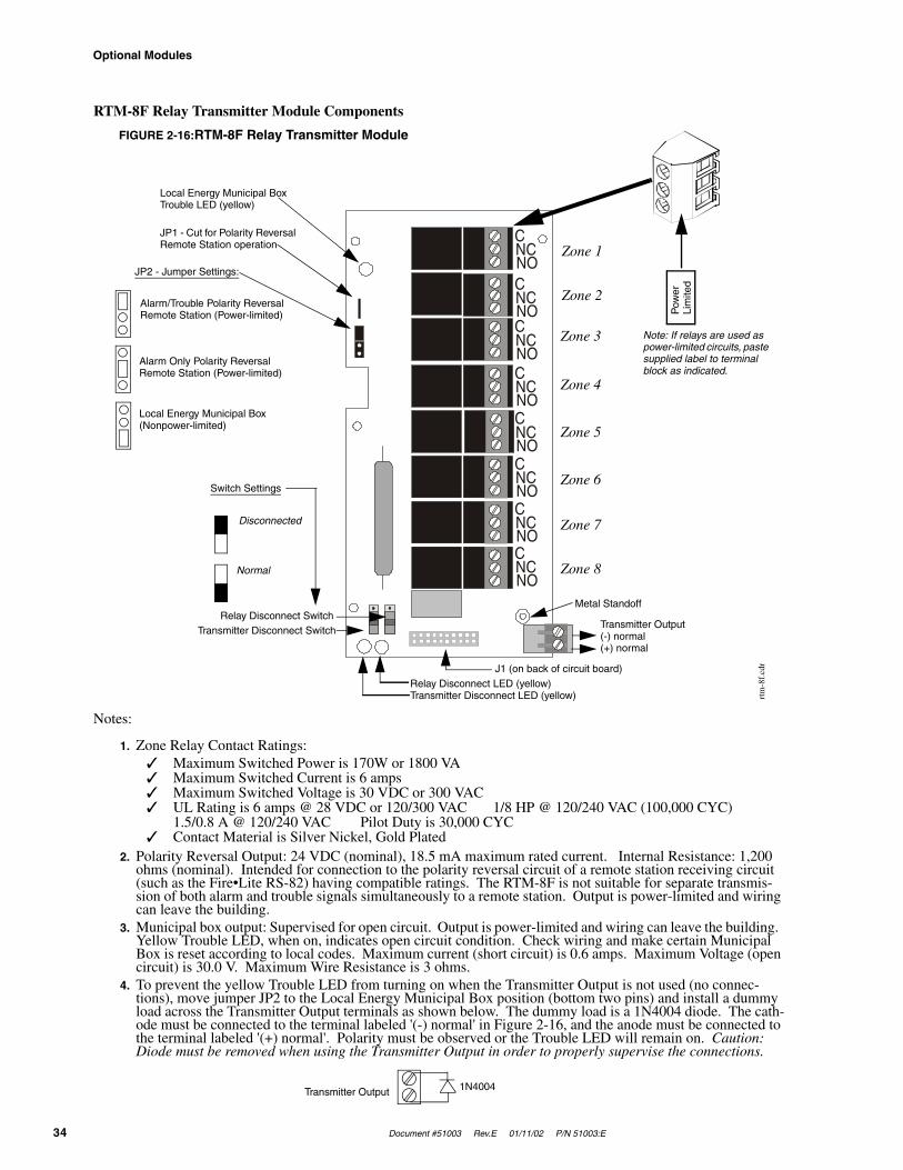
Optional Modules
34 Document #51003 Rev.E 01/11/02 P/N 51003:E
RTM-8F Relay Transmitter Module Components
Notes:
1. Zone Relay Contact Ratings:✓ Maximum Switched Power is 170W or 1800 VA✓ Maximum Switched Current is 6 amps✓ Maximum Switched Voltage is 30 VDC or 300 VAC✓ UL Rating is 6 amps @ 28 VDC or 120/300 VAC 1/8 HP @ 120/240 VAC (100,000 CYC)
1.5/0.8 A @ 120/240 VAC Pilot Duty is 30,000 CYC✓ Contact Material is Silver Nickel, Gold Plated
2. Polarity Reversal Output: 24 VDC (nominal), 18.5 mA maximum rated current. Internal Resistance: 1,200 ohms (nominal). Intended for connection to the polarity reversal circuit of a remote station receiving circuit (such as the Fire•Lite RS-82) having compatible ratings. The RTM-8F is not suitable for separate transmis-sion of both alarm and trouble signals simultaneously to a remote station. Output is power-limited and wiring can leave the building.
3. Municipal box output: Supervised for open circuit. Output is power-limited and wiring can leave the building. Yellow Trouble LED, when on, indicates open circuit condition. Check wiring and make certain Municipal Box is reset according to local codes. Maximum current (short circuit) is 0.6 amps. Maximum Voltage (open circuit) is 30.0 V. Maximum Wire Resistance is 3 ohms.
4. To prevent the yellow Trouble LED from turning on when the Transmitter Output is not used (no connec-tions), move jumper JP2 to the Local Energy Municipal Box position (bottom two pins) and install a dummy load across the Transmitter Output terminals as shown below. The dummy load is a 1N4004 diode. The cath-ode must be connected to the terminal labeled '(-) normal' in Figure 2-16, and the anode must be connected to the terminal labeled '(+) normal'. Polarity must be observed or the Trouble LED will remain on. Caution: Diode must be removed when using the Transmitter Output in order to properly supervise the connections.
C
C
C
C
C
C
C
C
NC
NC
NC
NC
NC
NC
NC
NC
NO
NO
NO
NO
NO
NO
NO
NO
FIGURE 2-16:RTM-8F Relay Transmitter Module
Pow
erLi
mite
d
Note: If relays are used as power-limited circuits, paste supplied label to terminal block as indicated.
Zone 1
Zone 2
Zone 3
Zone 4
Zone 5
Zone 6
Zone 7
Zone 8
Relay Disconnect LED (yellow)Transmitter Disconnect LED (yellow)
Transmitter Output(-) normal(+) normal
Metal Standoff
J1 (on back of circuit board)
Relay Disconnect SwitchTransmitter Disconnect Switch
Switch Settings
Disconnected
Normal
JP2 - Jumper Settings:
Alarm/Trouble Polarity Reversal Remote Station (Power-limited)
Alarm Only Polarity Reversal Remote Station (Power-limited)
Local Energy Municipal Box (Nonpower-limited)
Local Energy Municipal Box Trouble LED (yellow)
JP1 - Cut for Polarity Reversal Remote Station operation
rtm
-8f.
cdr
1N4004Transmitter Output

Document #51003 Rev.E 01/11/02 P/N 51003:E 35
Printer/PC and Terminal Mode Annunciator Interface
2.9 Printer/PC and Terminal Mode Annunciator Interface
A serial printer, personal computer or Terminal Mode annunciator may be connected to TB7 on the FACP main cir-cuit board. Switch SW3, located on the bottom center of the main circuit board, must be set to configure terminal block TB7 for the appropriate device. Placing SW3 in the ‘up’ position (RS-232 PC/Printer) will allow connection of most 40 and 80 column printers and most IBM PC/XT/AT or compatible computers including laptops and personal computers. Placing SW3 in the ‘down’ position (RS-485 Terminal Mode) will allow connection of most Terminal Mode annunciators.
CAUTION: DO NOT connect a printer or PC to the MS-9200 FACP if a ground fault exists on the control panel. Circuit damage may result. Remove all power (AC and DC) before installing or removing any modules or wiring.
Programming
Refer to “System Edit” on page 45, for printer programming instructions.
Installation
Remote printers and PCs require 120 VAC, 50/60 Hz primary power. Also required is an interface cable prewired to a DB9F connector (cable P/N: 75267) as shown in Figure 2-17 and a DB25 adapter. Connect the interface cable to TB7 on the MS-9200 main circuit board and the attached cable to the serial EIA-232 port on the printer or PC. Use the DB25 adapter if a nine pin connector is not available on your printer or PC. Note that a ground fault may occur on the MS-9200 panel, dependent on the printer used, when this connection is made. For this reason, it is important that there be no preexisting ground fault on the panel. Consult the factory for recommended printers.
Printer Configuration
Refer to the documentation supplied with the printer for additional pertinent information. Set the printer's options as listed in the following table.
PC Configuration
The Windows-based PK-9200W Programming Utility Kit contains four 3½" floppy disks and the Instruction Manual P/N 50684.
TABLE 2-1: Typical Printer SettingsCOMMUNICATION SETUP
BUFFER: LARGEDATA BITS: 7
PARITY: EVENSTOP BIT: 1 STOP
BAUD RATE: 2400
!
SUPV ALARM TROUBLE PC/PRINTER TERM COMMNO C NO NC C NO NC C A B B+ A+ B- A- 1 COMM 2
ACS SHIELD SLC SLCOUT+ IN+ OUT- IN-
TB3
TB7
TB5
TB6
Black
RCV GRND
TX
5 4 3 2 1
9 8 7 6Green
Jumper
Red
FIGURE 2-17:Remote Serial Printer and Computer Connections
MS-9200
TB7
Plug this DB9F connector into the EIA-232 port of the printer or PC.
Cable Assembly P/N: 75267
9200
tb7.
cdr
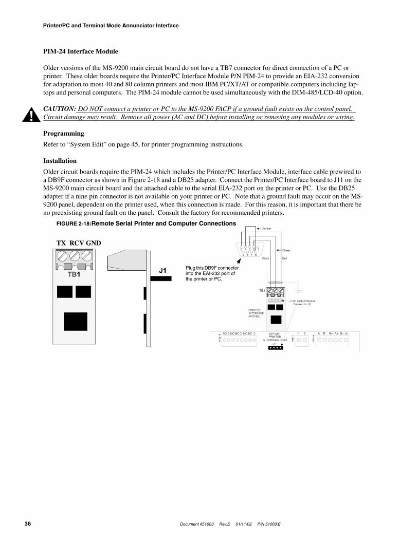
Printer/PC and Terminal Mode Annunciator Interface
36 Document #51003 Rev.E 01/11/02 P/N 51003:E
PIM-24 Interface Module
Older versions of the MS-9200 main circuit board do not have a TB7 connector for direct connection of a PC or printer. These older boards require the Printer/PC Interface Module P/N PIM-24 to provide an EIA-232 conversion for adaptation to most 40 and 80 column printers and most IBM PC/XT/AT or compatible computers including lap-tops and personal computers. The PIM-24 module cannot be used simultaneously with the DIM-485/LCD-40 option.
CAUTION: DO NOT connect a printer or PC to the MS-9200 FACP if a ground fault exists on the control panel. Circuit damage may result. Remove all power (AC and DC) before installing or removing any modules or wiring.
Programming
Refer to “System Edit” on page 45, for printer programming instructions.
Installation
Older circuit boards require the PIM-24 which includes the Printer/PC Interface Module, interface cable prewired to a DB9F connector as shown in Figure 2-18 and a DB25 adapter. Connect the Printer/PC Interface board to J11 on the MS-9200 main circuit board and the attached cable to the serial EIA-232 port on the printer or PC. Use the DB25 adapter if a nine pin connector is not available on your printer or PC. Note that a ground fault may occur on the MS-9200 panel, dependent on the printer used, when this connection is made. For this reason, it is important that there be no preexisting ground fault on the panel. Consult the factory for recommended printers.
!
FIGURE 2-18:Remote Serial Printer and Computer Connections
Plug this DB9F connector into the EAI-232 port of the printer or PC.
TX RCV GND
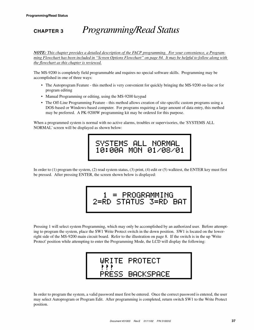
Document #51003 Rev.E 01/11/02 P/N 51003:E 37
Programming/Read Status
CHAPTER 3 Programming/Read Status
NOTE: This chapter provides a detailed description of the FACP programming. For your convenience, a Program-ming Flowchart has been included in “Screen Options Flowchart” on page 84. It may be helpful to follow along with the flowchart as this chapter is reviewed.
The MS-9200 is completely field programmable and requires no special software skills. Programming may be accomplished in one of three ways:
• The Autoprogram Feature - this method is very convenient for quickly bringing the MS-9200 on-line or for program editing
• Manual Programming or editing, using the MS-9200 keypad
• The Off-Line Programming Feature - this method allows creation of site-specific custom programs using a DOS-based or Windows-based computer. For programs requiring a large amount of data entry, this method may be preferred. A PK-9200W programming kit may be ordered for this purpose.
When a programmed system is normal with no active alarms, troubles or supervisories, the 'SYSTEMS ALL NORMAL' screen will be displayed as shown below:
In order to (1) program the system, (2) read system status, (3) print, (4) edit or (5) walktest, the ENTER key must first be pressed. After pressing ENTER, the screen shown below is displayed:
Pressing 1 will select system Programming, which may only be accomplished by an authorized user. Before attempt-ing to program the system, place the SW1 Write Protect switch in the down position. SW1 is located on the lower-right side of the MS-9200 main circuit board. Refer to the illustration on page 8. If the switch is in the up 'Write Protect' position while attempting to enter the Programming Mode, the LCD will display the following:
In order to program the system, a valid password must first be entered. Once the correct password is entered, the user may select Autoprogram or Program Edit. After programming is completed, return switch SW1 to the Write Protect position.
SYSTEMS ALL NORMAL10:00A MON 01/08/01
1 = PROGRAMMING2=RD STATUS 3=RD BAT
WRITE PROTECT !!!PRESS BACKSPACE

Initial Power-up
38 Document #51003 Rev.E 01/11/02 P/N 51003:E
1 = Programming: There are two programming levels.
• Program Level 1 is for system configuration in which data relating to device types, zoning, messages, etc. is entered into the system memory
• Program Level 2 is where a qualified operator can access features such as Disable, Clear History, Walktest, Time Change and Program Check. For Program Level 2, the SW1 Write Protect switch should remain in the up 'Write Protect' position
2 = Read Status: Entering Read Status allows the user to read the status of any point/zone in the system plus display or print the history file or print the entire user program or print addressable smoke detector data readings. The Read Status feature is NOT password protected. Read Status is explained in “Operating Instructions” on page 51.
3 = Read BAT: Entering RD BAT allows the user to read the battery voltage. The RD BAT feature is NOT password protected. The following screen is displayed upon entering RD BAT:
“Initial Power-up” describes initial programming procedures for a new system. The same procedures are used to modify programming in an existing system. Make certain the SW1 Write Protect switch is in the down position before attempting any Level 1 Programming functions.
3.1 Initial Power-up
After completing the wiring of addressable devices to the SLC loop, power up the fire alarm system. Since the addressable devices have not yet been programmed into the FACP, their LEDs will not flash, the System Trouble LED will be on and the LCD display will alternate between the following two displays:
If the system remains unprogrammed, the piezo will sound after a few minutes. It can be silenced by pressing the Acknowledge/Step switch, but it will continue to resound until the system is programmed.
BATTERY: 24.00 V.
TROUBLE IN SYSTEMPROGRAM CORRUPTED
TROUBLE IN SYSTEMNO DEVICES INSTALL

Document #51003 Rev.E 01/11/02 P/N 51003:E 39
Programming
3.2 Programming
Press the ENTER key. The screen below will appear:
To enter the programming mode, press '1'. The display will read as follows:
Entering the Level 1 password (default 00000) will cause the following screen to appear (refer to “Program Change - Level One” on page 40):
Entering the Level 2 password (default 11111) will cause the following screen to appear (refer to “Program Change - Level 2” on page 47):
Passwords
There are two factory set programming passwords, '00000' and '11111', which will access two different screens as indicated in the preceding section. From either of the screens, access to specific system and device programming may be obtained. All programming entries are stored in nonvolatile memory. The factory set passwords can be changed by the user and a method exists to clear one or both passwords. Note that for Canadian applications, both passwords must be changed from the factory settings. If an invalid password is entered, the display will read 'INCORRECT PASSWORD'. To exit from Programming operations at any time, press the Backspace (left arrow) key repeatedly.
1 = PROGRAMMING2=RD STATUS 3=RD BAT
KEY PASSWORD, ENTER
0=CLR 1=AUTO 2=POINT3=SYS 4=PWORD 5=LOAD
1=DISABL 2=CLR HIST3=WALK 4=TIME 5=CHEK

Program Change - Level One
40 Document #51003 Rev.E 01/11/02 P/N 51003:E
3.3 Program Change - Level One
When the correct password is entered, the MS-9200 will enter Level 1 program mode. In this mode, the trouble relay is activated and the System Trouble LED flashes and cannot be changed to steady and the piezo sounder is off. The following display will appear:
3.3.1 Clear
Pressing '0' will clear all general system programming options described in “System Edit” on page 45, and all pro-grammed addressable devices from the nonvolatile memory of the MS-9200. Before executing the Clear command, the display will prompt the user to press ENTER in order to verify the command before the system actually clears programming data. CLEAR is a useful command when the unit is first installed, prior to autoprogramming. Note that it is necessary to 'Autoprogram' after using the clear function.
3.3.2 Autoprogram
Pressing '1' enters the Autoprogramming mode. The main purpose of autoprogramming is to allow the installer a fast and easy way to bring the system on-line as quickly as possible. The first time the system is brought on-line, it must be autoprogrammed. Autoprogram is also the only way to add or delete devices.
Once Autoprogram is selected, the MS-9200 automatically polls all devices installed/wired to the SLC loop. The panel communicates with each individual addressable device and displays the type of device at each address location starting with detectors and then modules.
While autoprogramming the system, the MS-9200 will display the following:
Verification of each device address and type installed on the SLC may now occur. If information is correct, press the ENTER key, if incorrect, press the left arrow key to delete. In addition, adjective and noun descriptors plus zone assignments may be added to the display field per device address. If the Reset key is pressed at this time or the panel is allowed to time-out after 10 minutes of inactivity, a 'System Corrupted' message will appear. Be certain to step through all devices, using the Enter or left arrow key.
The first time that autoprogramming is selected, all points installed on the SLC loop are identified. Default device type (monitor, smoke detector, control) and software zone assignments for each device are displayed. On any succes-sive enabling of the autoprogram feature, the LCD will display only the newly installed, deleted or changed devices on the SLC loop.
Devices which match the program already in memory are not changed and are not shown to the operator. Devices which do not match the program (not the same address and/or type) are shown to the operator. Devices inadvertently set to the same address are identified and displayed on the screen.
0=CLR 1=AUTO 2=POINT3=SYS 4=PWORD 5=LOAD
AUTOPROGRAMPLEASE WAIT

Document #51003 Rev.E 01/11/02 P/N 51003:E 41
Program Change - Level One
New Detectors
For each new detector, the Autoprogram feature selects default program values and presents the information to the user. A typical example follows:
In the preceding example:
• 'P' in 'P01' represents the actual type code (photoelectric) of the detector found at address 01. ('I' would repre-sent an Ionization detector)
• The ADJ (adjective) and NOUN fields are blank, but may be user programmed
• 'Z00' is the default zone selection meaning 'general alarm' (main circuit board NAC outputs 1 & 2). Refer to “Software Zones” on page 65, for software zone assignments.
After the new detector is displayed, press ENTER to accept the default information shown or press the left arrow (tri-angle to the left of ENTER) to reject the autoprogram information and not enter it into memory. In most cases, adjec-tive, noun descriptors and zone assignments will be added by using the following procedure.
The MS-9200 will lead you through the program editing process. A blinking cursor moves through the fields as you press the right arrow key (triangle to the right of ENTER). After moving into other fields, you may return to a previ-ous field by pressing the left arrow. Change the blinking fields by pressing the up arrow key, the down arrow key or by pressing the appropriate numeric key.
Custom words may be entered via the keypad. The alphanumeric operation of the keypad changes a blinking letter in the ADJ and NOUN fields. For example, to enter the letter 'R', repeatedly press the 7 key to step through 7, P, R and S, stopping when R is displayed. Press the right arrow key (do not press ENTER at this time) to move to the next let-ter display position.
To reduce the number of key presses, the user may also select from a library of stored words. The ADJ field library provides five-character words selected by the up arrow or down arrow keys from the following list of available words:
The ADJ (adjective) field may be loaded from the library list above and then modified letter-by-letter if desired. Pressing the up or down arrow keys steps through the library. Once the up or down arrow keys are pressed, the blink-ing cursor moves to the last character of the ADJ field, assuming that the user will next want to move beyond this field.
Pressing a key on the 12-key pad changes the letter indicated by the blinking cursor. Any alphanumeric character may be entered. Pressing the right or left arrow key moves the blinking cursor one letter right or left. When the right arrow key is pressed with the blinking cursor on the last letter of the ADJ label, the cursor will move to the first letter of the NOUN field.
PROGRAM SMOKE DET P01<ADJ> <NOUN> Z00
_____ (default of blanks)NORTHSOUTH_EAST_WESTFRONTCENTR_REARUPPERLOWER_MAIN
FIRST__2ND__3RD__4TH__5THFLR_1FLR_2FLR_3FLR_4FLR_5RM___

Program Change - Level One
42 Document #51003 Rev.E 01/11/02 P/N 51003:E
Altering the NOUN field is done in a similar way. Use the up or down arrow keys to step through the NOUN library which is listed below:
In addition, the user may use the Recall/Increment function at any time when the cursor is on the first letter of the ADJ or NOUN field as follows:
• If the zero is pressed, a '0' is placed in the first letter position
• If the zero key is then pressed a second time with no intervening key actions, the entire ADJ field is replaced with the field entered for the previous device programmed, and the cursor moves to the last character of the field (Recall function). The Recalled ADJ or NOUN field may now be changed letter-by-letter
• If the Zero key is pressed again with no other intervening key actions and the last character in the field is a number '0-9', the number is incremented by one. If the last character is a letter, it changes to a '0'. If the last character goes from 9 to 0 and the characters to the left of the last character are also numbers, they are also incremented (overflow)
• The above increment function may be repeated with each press of the Zero key
As an example, the user could quickly enter 'FLR_3_ROOM_305' as follows:
1. The cursor is on the first letter of the ADJ field. Press the Zero key twice to display 'FLR_3'
2. With the cursor on the first letter of the NOUN field, press the zero key twice to recall the display 'ROOM_304'. The cursor automatically jumps from the first to the last letter of the NOUN field
3. With the cursor on the last letter of the NOUN field, press the Zero key again to increment the room number to '305'
4. Press the right arrow key to advance to the Zone field
5. Select a zone number from 00 to 56. Z00 (default zone) is the general alarm zone. Z01 through Z56 may be selected to link software zones.
To load the addressable device's program into memory at any time, press the ENTER key. After pressing ENTER, autoprogram displays the next new detector. If a detector had been previously entered into memory, but is missing (no answer), the display shows the following:
_________ (default of blanks)BASEMENT_BOILER_RMCLASSROOMCLOSET___CORRIDOR_ELECT._RMELEVATOR_ENTRANCE_FLOOR____GARAGE___HALLWAY__
HVAC_ROOMKITCHEN__LOBBY____OFFICE___PATIENT__RESTROOM_ROOM_____STAIRWAY_STOREROOMWING_____ZONE_____
PROGRAM SMOKE DET P01NO ANSWER DELETE?
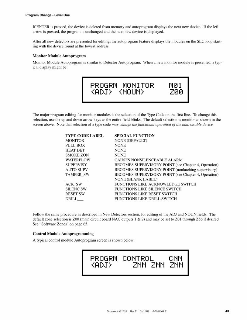
Document #51003 Rev.E 01/11/02 P/N 51003:E 43
Program Change - Level One
If ENTER is pressed, the device is deleted from memory and autoprogram displays the next new device. If the left arrow is pressed, the program is unchanged and the next new device is displayed.
After all new detectors are presented for editing, the autoprogram feature displays the modules on the SLC loop start-ing with the device found at the lowest address.
Monitor Module Autoprogram
Monitor Module Autoprogram is similar to Detector Autoprogram. When a new monitor module is presented, a typ-ical display might be:
The major program editing for monitor modules is the selection of the Type Code on the first line. To change this selection, use the up and down arrow keys as the entire field blinks. The default selection is monitor as shown in the screen above. Note that selection of a type code may change the functional operation of the addressable device.
Follow the same procedure as described in New Detectors section, for editing of the ADJ and NOUN fields. The default zone selection is Z00 (main circuit board NAC outputs 1 & 2) and may be set to Z01 through Z56 if desired. See “Software Zones” on page 65.
Control Module Autoprogramming
A typical control module Autoprogram screen is shown below:
PROGRM MONITOR M01<ADJ> <NOUN> Z00
TYPE CODE LABELMONITORPULL BOXHEAT DETSMOKE ZONWATERFLOWSUPERVISYAUTO SUPVTAMPER_SW___________ACK_SW___SILENC SWRESET SWDRILL___
SPECIAL FUNCTIONNONE (DEFAULT)NONENONENONECAUSES NONSILENCEABLE ALARMBECOMES SUPERVISORY POINT (see Chapter 4, Operation)BECOMES SUPERVISORY POINT (nonlatching supervisory)BECOMES SUPERVISORY POINT (see Chapter 4, Operation)NONE (BLANK LABEL)FUNCTIONS LIKE ACKNOWLEDGE SWITCHFUNCTIONS LIKE SILENCE SWITCHFUNCTIONS LIKE RESET SWITCHFUNCTIONS LIKE DRILL SWITCH
PROGRM CONTROL CNN<ADJ> ZNN ZNN ZNN

Program Change - Level One
44 Document #51003 Rev.E 01/11/02 P/N 51003:E
Control modules default to Zone 00 (general alarm). All type code options are silenceable except Relay and Strobes. The selection of control module type codes may change their function. Select the type code from the library list below. Use the arrow keys as described in the New Detectors section.
Select an adjective descriptor from the library list shown in the New Detectors section. Use the arrow keys as described in the New Detectors section. Control modules may be assigned to a maximum of three software zones (refer to “Software Zones” on page 65). Zone Z00 represents general alarm. All control modules are assigned to Zone Z00 upon initial power-up.
3.3.3 Point Edit
While displaying the Program Level 1 Menu screen (see “Program Change - Level One” on page 40), pressing '2' allows for editing of the point (addressable device) descriptor screens. These screens show the device type, the device address, adjective and noun field descriptors and the software zone locations that the point is assigned to. Point editing is performed after autoprogramming and may be done at any time, except during an alarm condition. The following display will appear:
For example, select Detector address 3 program edit by pressing * key (* = detector), followed by numeric key '3', followed by ENTER. Select Module address 3 program edit by pressing the # key (# = module), followed by the numeric key '3', followed by ENTER. If there is no device installed at this address , the panel displays the next higher address where a device is installed. After editing is complete and ENTER is pressed, the display returns to the above menu. Rather than reentering the next point number, the user may press the up or down arrow key to display the next lower or higher existing point. Using software P/N 73750 or greater, to edit NAC 1 or NAC 2, press the * key, then the # key, the press '1' for NAC 1 or '2' for NAC 2. Select either 'BELL_CKT' for silenceable functionality or 'STROBE' for nonsilenceable functionality. Use the system edit menu described in “System Edit” on page 45, to select coding. Coding is only possible if the NAC is programmed as 'BELL_CKT'. The point display formats and the method of editing are described in “Autoprogram” on page 40.
TYPE CODE
1 CONTROL2 BELL CKT3 HORN CKT4 SOUNDERS5 ___________6 RELAY7 STROBES
SPECIAL FUNCTION
NONE (DEFAULT) SilenceableSilenceableSilenceableSilenceable(BLANK LABEL) SilenceableIGNORE OPEN CIRCUIT (Nonsilenceable)Nonsilenceable
POINT PROG. EDITPRESS */#,AA,ENTER

Document #51003 Rev.E 01/11/02 P/N 51003:E 45
Program Change - Level One
3.3.4 System Edit
The System Edit function is selected by pressing '3'. The system edit screen appears as shown below for software releases prior to P/N 73750. This software does not support the LCD-40 Annunciator.
Use the up and down arrow keys to scroll through the choices for each option and the left and right arrow keys to move from option to option.
There are eight system function options for software releases prior to P/N 73750. The factory default selections and user option selections are shown below:
The system edit screen appears as shown below for software P/N 73750 or greater. This software is required to support the LCD-40 Series Annunciators.
VF=N SI=N AS=N PS=NCD=N AN=N ST=4 REM=N
FUNCTION DEFAULT SELECTION
VF = Alarm Verification (N)one (Y) 73 secondsSI = Silence Inhibit (N)one (Y) 60 seconds1
AS = Autosilence (N)one (Y) 10 minutes1
PS = Presignal (N)one (Y) 3 minutes with 15 second Acknowledge1
CD = Bell Code 1 (M)arch Time (N)one = No Coding (steady)Note: Bell 2 is fixed steady (T) = Temporal
(C) = CaliforniaAN = Annunciators (N)one (Z) = 56 Zones
(ZU) = 56 Zones Annunciator with UDACT-F2
(P) = 198 Points(PU) = 198 Points Annunciator with UDACT-F2
ST = SLC loop style (4) = Style 4 (6) = Style 6REM = Alarm/Trbl Reminder (N)o (Y)es = Sound onboard piezo every 15 seconds
during alarm and every two minutes during trouble after acknowledge or silence key has been pressed.
1Requires prior approval of Local Authority Having Jurisdiction.
2When the UDACT-F has a fault, this entry allows the FACP to display 'DACT Trouble' on the LCD display and printer hardcopy. The his-tory file will also be updated with this information. For zone annunciation, up to 56 zones, use AFM Series Annunciators or LDM Series Annunciators. For 198 point annunciation, use the LDM Series Annunciators.
V=N I=N A=N P=N C=NA/U=N L/P=N S=4 R=N
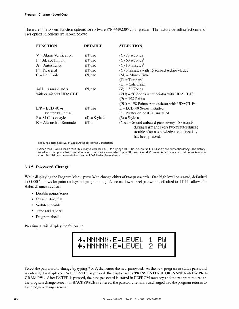
Program Change - Level One
46 Document #51003 Rev.E 01/11/02 P/N 51003:E
There are nine system function options for software P/N #M9200V20 or greater. The factory default selections and user option selections are shown below:
3.3.5 Password Change
While displaying the Program Menu, press '4' to change either of two passwords. One high level password, defaulted to '00000', allows for point and system programming. A second lower level password, defaulted to '11111', allows for status changes such as:
• Disable points/zones
• Clear history file
• Walktest enable
• Time and date set
• Program check
Pressing '4' will display the following:
Select the password to change by typing * or #, then enter the new password. As the new program or status password is entered, it is displayed. When ENTER is pressed, the display reads 'PRESS ENTER IF OK, NNNNN=NEW PRO-GRAM PW'. After ENTER is pressed, the new password is stored in EEPROM memory and the program returns to the program change screen. If BACKSPACE is entered, the password remains unchanged and the program returns to the program change screen.
FUNCTION DEFAULT SELECTION
V = Alarm Verification (N)one (Y) 73 secondsI = Silence Inhibit (N)one (Y) 60 seconds1
A = Autosilence (N)one (Y) 10 minutes1
P = Presignal (N)one (Y) 3 minutes with 15 second Acknowledge1
C = Bell Code (N)one (M) = March Time(T) = Temporal(C) = California
A/U = Annunciators (N)one (Z) = 56 Zoneswith or without UDACT-F (ZU) = 56 Zones Annunciator with UDACT-F2
(P) = 198 Points(PU) = 198 Points Annunciator with UDACT-F2
L/P = LCD-40 or (N)one L = LCD-40 Series installed Printer/PC in use P = Printer or local PC installedS = SLC loop style (4) = Style 4 (6) = Style 6R = Alarm/Trbl Reminder (N)o (Y)es = Sound onboard piezo every 15 seconds
during alarm and every two minutes during trouble after acknowledge or silence key
has been pressed.
1Requires prior approval of Local Authority Having Jurisdiction.
2When the UDACT-F has a fault, this entry allows the FACP to display 'DACT Trouble' on the LCD display and printer hardcopy. The history file will also be updated with this information. For zone annunciation, up to 56 zones, use AFM Series Annunciators or LDM Series Annunci-ators. For 198 point annunciation, use the LDM Series Annunciators.
*,NNNNN,E=LEVEL 1 PW#,NNNNN,E=LEVEL 2 PW

Document #51003 Rev.E 01/11/02 P/N 51003:E 47
Program Change - Level 2
3.3.6 Load
While displaying the Program Menu, program selection '5' sets up the MS-9200 for transfer of its application data-base from/to a DOS-based or Window-based computer. This may be used to save the program that exists in an MS-9200 for security and future service reasons; or may be used to transfer a program created off-line to the MS-9200. Refer to the PK-9200W Manual for additional information. When the Load option is selected, the follow-ing screen will be displayed:
The left arrow key may be used to return to the program change screen. The PC connects to the EIA-232 printer interface (instructions provided with the Upload/Download software kit). Continue to press the left arrow key to return to the main program screen.
3.4 Program Change - Level 2
While the MS-9200 system is normal with no active alarms, troubles or supervisories, the screen shown below will be displayed:
To access the programming mode, the ENTER key must be pressed, causing the following screen to be displayed:
Pressing '1' will cause the following screen to appear:
CONNECT COMPUTER NOWRUN PROGRAM FROM PC.
SYSTEMS ALL NORMAL10:00A MON 01/08/01
1 = PROGRAMMING2=RD STATUS 3=RD BAT
KEY PASSWORD, ENTER
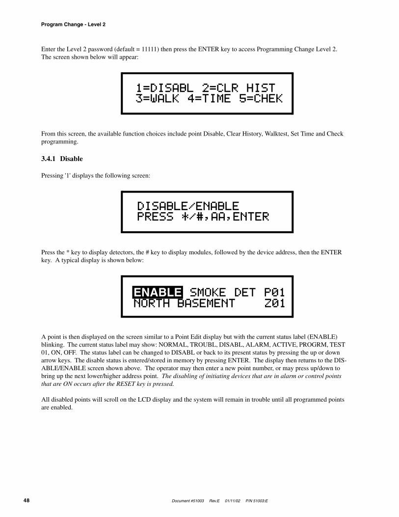
Program Change - Level 2
48 Document #51003 Rev.E 01/11/02 P/N 51003:E
Enter the Level 2 password (default = 11111) then press the ENTER key to access Programming Change Level 2. The screen shown below will appear:
From this screen, the available function choices include point Disable, Clear History, Walktest, Set Time and Check programming.
3.4.1 Disable
Pressing '1' displays the following screen:
Press the * key to display detectors, the # key to display modules, followed by the device address, then the ENTER key. A typical display is shown below:
A point is then displayed on the screen similar to a Point Edit display but with the current status label (ENABLE) blinking. The current status label may show: NORMAL, TROUBL, DISABL, ALARM, ACTIVE, PROGRM, TEST 01, ON, OFF. The status label can be changed to DISABL or back to its present status by pressing the up or down arrow keys. The disable status is entered/stored in memory by pressing ENTER. The display then returns to the DIS-ABLE/ENABLE screen shown above. The operator may then enter a new point number, or may press up/down to bring up the next lower/higher address point. The disabling of initiating devices that are in alarm or control points that are ON occurs after the RESET key is pressed.
All disabled points will scroll on the LCD display and the system will remain in trouble until all programmed points are enabled.
1=DISABL 2=CLR HIST3=WALK 4=TIME 5=CHEK
DISABLE/ENABLEPRESS */#,AA,ENTER
ENABLE SMOKE DET P01NORTH BASEMENT Z01
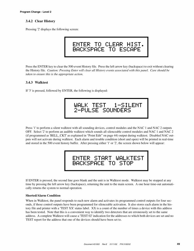
Document #51003 Rev.E 01/11/02 P/N 51003:E 49
Program Change - Level 2
3.4.2 Clear History
Pressing '2' displays the following screen:
Press the ENTER key to clear the 500-event History file. Press the left arrow key (backspace) to exit without clearing the History file. Caution: Pressing Enter will clear all History events associated with this panel. Care should be taken to ensure this is the appropriate action.
3.4.3 Walktest
If '3' is pressed, followed by ENTER, the following is displayed:
Press '1' to perform a silent walktest with all sounding devices, control modules and the NAC 1 and NAC 2 outputs OFF. Select '2' to perform an audible walktest which sounds all silenceable control modules and NAC 1 and NAC 2 (if programmed as 'BELL_CKT' as explained in “Point Edit” on page 44) output during walktest. Disabled NAC out-puts will not activate during walktest. Each alarm and trouble condition (short and open) will be printed in real-time and stored in the 500 event history buffer. After pressing either '1' or '2', the screen shown below will appear:
If ENTER is pressed, the second line goes blank and the unit is in Walktest mode. Walktest may be stopped at any time by pressing the left arrow key (backspace), returning the unit to the main screen. A one hour time-out automati-cally returns the system to normal operation.
Shorted/Alarm Condition
When in Walktest, the panel responds to each new alarm and activates its programmed control outputs for four sec-onds, if those control outputs have been programmed for silenceable activation. It also stores each alarm in the his-tory file and printer with a 'TEST XX' status label. XX is a count of the number of times a device with this address has been tested. Note that this is a convenient way to identify two detectors that are erroneously set to the same address. A complete Walktest will cause a 'TEST 02' indication for the addresses to which both devices are set and no TEST report for the address that one of the devices should have been set to.
ENTER TO CLEAR HIST.BACKSPACE TO ESCAPE
WALK TEST 1-SILENT2-PULSE SOUNDERS
ENTER START WALKTESTBACKSPACE TO STOP
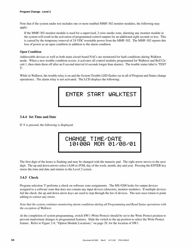
Program Change - Level 2
50 Document #51003 Rev.E 01/11/02 P/N 51003:E
Note that if the system under test includes one or more enabled MMF-302 monitor modules, the following may apply:
If the MMF-302 monitor module is used for a supervised, 2-wire smoke zone, alarming any monitor module in the system will result in the activation of programmed control outputs for an additional eight seconds or less. This is caused by the temporary removal of 24 VDC resettable power from the MMF-302. The MMF-302 reports this loss of power as an open condition in addition to the alarm condition.
Open Condition
Addressable devices as well as both main circuit board NACs are monitored for fault conditions during Walktest mode. When a new trouble condition occurs, it activates all control modules programmed for Walktest and Bell Cir-cuit 1, then shuts them off after an 8 second interval (4 seconds longer than alarms). The trouble status label is 'TEST T'.
While in Walktest, the trouble relay is on and the System Trouble LED flashes (as in all of Program and Status change operations). The alarm relay is not activated. The LCD displays the following:
3.4.4 Set Time and Date
If '4' is pressed, the following is displayed:
The first digit of the hours is flashing and may be changed with the numeric pad. The right arrow moves to the next digit. The up and down arrows select (A)M or (P)M, day of the week, month, day and year. Pressing the ENTER key stores the time and date and returns to the Level 2 screen.
3.4.5 Check
Program selection '5' performs a check on software zone assignments. The MS-9200 looks for output devices assigned to a software zone that does not contain any input devices (detectors, monitor modules). If multiple devices fail the check, the up and down arrow keys are used to step through the list of devices. The user must return to point editing to correct any errors.
Note that the system continues monitoring alarm conditions during all Programming and Read Status operations with the exception of Walktest.
At the completion of system programming, switch SW1 (Write Protect) should be set to the Write Protect position to prevent inadvertent changes to programmed features. Slide the switch to the up position to select the Write Protect feature. Refer to Figure 2-8, “Option Module Locations,” on page 29, for the location of SW1.
ENTER START WALKTEST
CHANGE TIME/DATE 10:00A MON 01/08/01
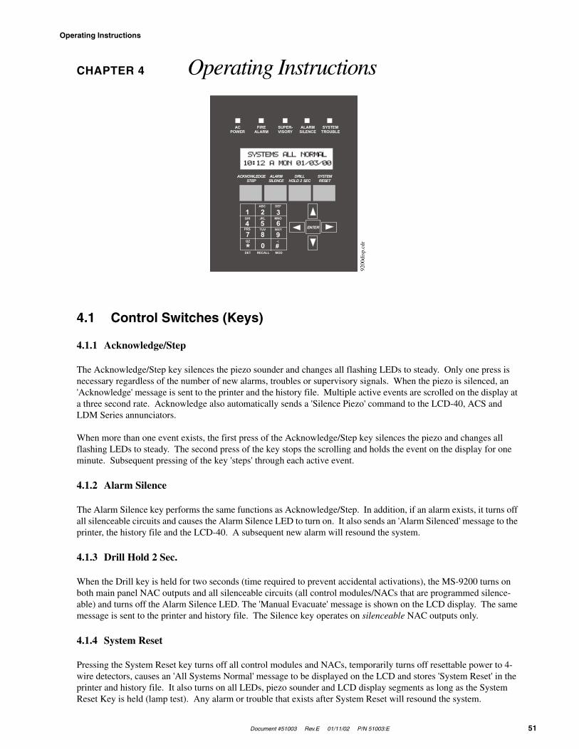
Document #51003 Rev.E 01/11/02 P/N 51003:E 51
Operating Instructions
CHAPTER 4 Operating Instructions
4.1 Control Switches (Keys)
4.1.1 Acknowledge/Step
The Acknowledge/Step key silences the piezo sounder and changes all flashing LEDs to steady. Only one press is necessary regardless of the number of new alarms, troubles or supervisory signals. When the piezo is silenced, an 'Acknowledge' message is sent to the printer and the history file. Multiple active events are scrolled on the display at a three second rate. Acknowledge also automatically sends a 'Silence Piezo' command to the LCD-40, ACS and LDM Series annunciators.
When more than one event exists, the first press of the Acknowledge/Step key silences the piezo and changes all flashing LEDs to steady. The second press of the key stops the scrolling and holds the event on the display for one minute. Subsequent pressing of the key 'steps' through each active event.
4.1.2 Alarm Silence
The Alarm Silence key performs the same functions as Acknowledge/Step. In addition, if an alarm exists, it turns off all silenceable circuits and causes the Alarm Silence LED to turn on. It also sends an 'Alarm Silenced' message to the printer, the history file and the LCD-40. A subsequent new alarm will resound the system.
4.1.3 Drill Hold 2 Sec.
When the Drill key is held for two seconds (time required to prevent accidental activations), the MS-9200 turns on both main panel NAC outputs and all silenceable circuits (all control modules/NACs that are programmed silence-able) and turns off the Alarm Silence LED. The 'Manual Evacuate' message is shown on the LCD display. The same message is sent to the printer and history file. The Silence key operates on silenceable NAC outputs only.
4.1.4 System Reset
Pressing the System Reset key turns off all control modules and NACs, temporarily turns off resettable power to 4-wire detectors, causes an 'All Systems Normal' message to be displayed on the LCD and stores 'System Reset' in the printer and history file. It also turns on all LEDs, piezo sounder and LCD display segments as long as the System Reset Key is held (lamp test). Any alarm or trouble that exists after System Reset will resound the system.
ACPOWER
ACKNOWLEDGESTEP
ALARMSILENCE
ENTER
DRILLHOLD 2 SEC
SYSTEMRESET
FIREALARM
SUPER-VISORY
ALARMSILENCE
SYSTEMTROUBLE
SYSTEMS ALL NORMAL10:12 A MON 01/03/00
1ABC DEF
MNOJKLGHI
PRS TUV WXY
QZ -/.
DET RECALL MOD
2 34 5 67 8 9
0* #
9200
disp
.cdr

LED Indicators
52 Document #51003 Rev.E 01/11/02 P/N 51003:E
4.2 LED Indicators
The six LED indicators on the front panel operate as follows:
AC Power
This is a green LED which illuminates if 120 VAC power is applied to the MS-9200(C) or 240 VAC power is applied to the MS-9200E.
Fire Alarm
This is a red LED that flashes when one or more alarms occur. It illuminates steady when the Acknowledge/Step or Alarm Silence key is pressed. The Alarm LED turns off when the System Reset key is pressed.
Supervisory
This is a yellow LED that flashes when one or more supervisory conditions occur, such as a sprinkler valve tamper condition. It illuminates steady when the Acknowledge/Step or Alarm Silence key is pressed. It turns off when System Reset is pressed.
Alarm Silence
This is a yellow LED that turns on after the Alarm Silence key is pressed (preceded by a fire alarm condition). It turns off when the Drill or System Reset key is pressed.
System Trouble
This is a yellow LED that flashes when one or more trouble conditions occur. It stays on steady when the Acknowl-edge/Step or Alarm Silence key is pressed. The LED turns off when all trouble conditions are cleared. This LED will also illuminate if the microprocessor watchdog circuit is activated.
4.3 Normal Operation
With no alarms or troubles in the system, the display message is 'Systems All Normal' along with the current time and date as shown below. To set the time and date, see “Set Time and Date” on page 50.
The MS-9200 performs the following functions at regular intervals while in normal mode:
✓ Polls all devices on SLC loop. Checks for valid reply, alarms, troubles, etc.
✓ Monitors AC input voltage and battery capacity
✓ Refreshes LCD display and updates time
✓ Scans keyboard
✓ Performs detector auto test
✓ Tests memory
✓ Update/Reads EIA-485 communications bus
SYSTEMS ALL NORMAL10:00A MON 01/08/01

Document #51003 Rev.E 01/11/02 P/N 51003:E 53
Trouble Operation
4.4 Trouble Operation
With no alarms, the detection of a trouble in the system will cause the piezo to sound, the System Trouble LED to flash and the trouble relay to activate. A message will appear on the LCD display indicating the trouble condition. The same message is sent to the printer and history file along with time and date. A ground fault will also cause the yellow Ground Fault LED, located on the bottom of the main circuit board, to turn on.
Addressable Smoke Detectors
For addressable Ionization or Photoelectric smoke detectors, the following is a typical message that could appear on the LCD display for a detector in trouble.
The information displayed in the first line in the example above provides the following information:
• The type of event - in this example, TRBL indicates Device Trouble
• The Specific Device Trouble for a Detector - the # symbol will be replace by a digit representing a specific trouble condition (refer to the list of Specific Device Troubles listed below)
• Type of device - in this example, SMOKE DET indicates smoke detector
• Point type and address - in this example, P01 indicates Photoelectric detector assigned to address 01
The information displayed in the second line in the example above provides the following information:
• <ADJ> - user programmed adjective descriptor from library list or custom entry (five characters maximum)
• <NOUN> - user programmed noun descriptor from library list or custom entry (ten characters maximum)
• Zone - zone to which the point is assigned
The # symbol in the display will be replaced by a digit that represents the Specific Device Troubles as listed below:
TABLE 4-1: Specific Device Troubles for a Detector
# Specific Device Troubles
1
An Invalid Reply may be due to:(1) incorrect pulse width received from a detector(2) no answer from a detector due to either a complete device failure or removal from the SLC loop(3) an incorrect identification code received, i.e. a photo detector replaced by an ion detector or vice-versa
2Maintenance Alert - indicates that a detector has been within 80% of its alarm threshold for 24 hours, indicating that the detector needs cleaning
3Fail Automatic Test - indicates that a detector's sensing chamber and electronics (which are tested for nor-mal safe operation every two hours) has failed the test
TRBL # SMOKE DET P01<ADJ> <NOUN> Z00

Trouble Operation
54 Document #51003 Rev.E 01/11/02 P/N 51003:E
Monitor and Control Modules
The following is a typical message that could appear on the LCD display for monitor modules and control modules in trouble.
The information displayed in the first line in the previous example provides the following information:
• The type of event - in this example TRBL indicates Device Trouble
• The Specific Device Troubles for a module - the # symbol will be replaced by a digit representing a specific trouble condition (refer to the list of Specific Device Troubles for a module below)
• Type of device - in this example, MONITOR indicates a monitor module
• Point type and address - in this example, M01 indicates monitor module assigned to address 01
The information displayed in the second line in the previous example provides the following information:
• <ADJ> - user programmed adjective descriptor from library list or custom entry (five characters maximum)
• <NOUN> - user programmed noun descriptor from library list or custom entry (ten characters maximum)
• Zone - zone to which the point is assigned
The # symbol in the display will be replaced by a digit that represents the Specific Device Troubles as listed below:
Pressing the Acknowledge/Step key will cause the piezo to silence and the System Trouble LED to turn on steady. This occurs regardless of the number of troubles, alarms and supervisory events active in the system (block acknowl-edge). When the Acknowledge/Step key is pressed and at least one new alarm or trouble exists in the system, the 'Acknowledge' message is sent to the printer and history file. If the trouble clears, either before or after Acknowl-edge, the 'Clear Trouble' message is sent to the printer as illustrated by the following example:
CLR TRBL_# SMOKE DET P01 <ADJ><NOUN> ZONE# TIME and DATE
If all troubles clear and there are no supervisory or fire conditions active in the system, the system returns to normal operation status and the 'Systems All Normal' message is shown on the LCD display and stored in the history and printer files. Trouble restore occurs even if the troubles were never acknowledged (auto-restore).
If the Alarm Silence key is pressed when only troubles exist, it will have the same effect as the Acknowledge/Step key. The Alarm Silence LED will not be illuminated unless there was also an alarm in the system.
TABLE 4-2: Specific Device Troubles for a Module
# Specific Device Troubles
1
An Invalid Reply may be due to:(1) incorrect pulse width received from a module(2) no answer from a module due to either a complete device failure or removal from the SLC loop(3) an incorrect identification code received, i.e. a monitor module replaced by a control module or vice-versa
2 Short Circuit Control Module - indicates a short circuit exists across a control module's NAC
3Open Circuit Monitor/Control Module - indicates an open circuit exists on a control module’s NAC or the monitor module's Initiating Device Circuit
TRBL # MONITOR M01<ADJ> <NOUN> Z00
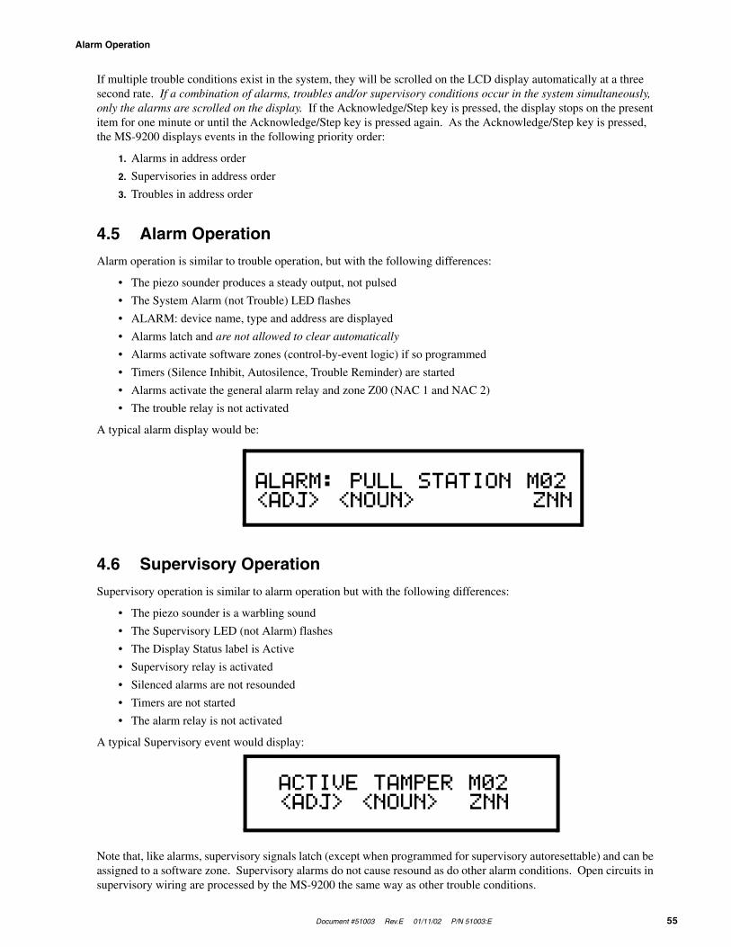
Document #51003 Rev.E 01/11/02 P/N 51003:E 55
Alarm Operation
If multiple trouble conditions exist in the system, they will be scrolled on the LCD display automatically at a three second rate. If a combination of alarms, troubles and/or supervisory conditions occur in the system simultaneously, only the alarms are scrolled on the display. If the Acknowledge/Step key is pressed, the display stops on the present item for one minute or until the Acknowledge/Step key is pressed again. As the Acknowledge/Step key is pressed, the MS-9200 displays events in the following priority order:
1. Alarms in address order
2. Supervisories in address order
3. Troubles in address order
4.5 Alarm Operation
Alarm operation is similar to trouble operation, but with the following differences:
• The piezo sounder produces a steady output, not pulsed
• The System Alarm (not Trouble) LED flashes
• ALARM: device name, type and address are displayed
• Alarms latch and are not allowed to clear automatically
• Alarms activate software zones (control-by-event logic) if so programmed
• Timers (Silence Inhibit, Autosilence, Trouble Reminder) are started
• Alarms activate the general alarm relay and zone Z00 (NAC 1 and NAC 2)
• The trouble relay is not activated
A typical alarm display would be:
4.6 Supervisory Operation
Supervisory operation is similar to alarm operation but with the following differences:
• The piezo sounder is a warbling sound
• The Supervisory LED (not Alarm) flashes
• The Display Status label is Active
• Supervisory relay is activated
• Silenced alarms are not resounded
• Timers are not started
• The alarm relay is not activated
A typical Supervisory event would display:
Note that, like alarms, supervisory signals latch (except when programmed for supervisory autoresettable) and can be assigned to a software zone. Supervisory alarms do not cause resound as do other alarm conditions. Open circuits in supervisory wiring are processed by the MS-9200 the same way as other trouble conditions.
ALARM: PULL STATION M02<ADJ> <NOUN> ZNN
ACTIVE TAMPER M02<ADJ> <NOUN> ZNN
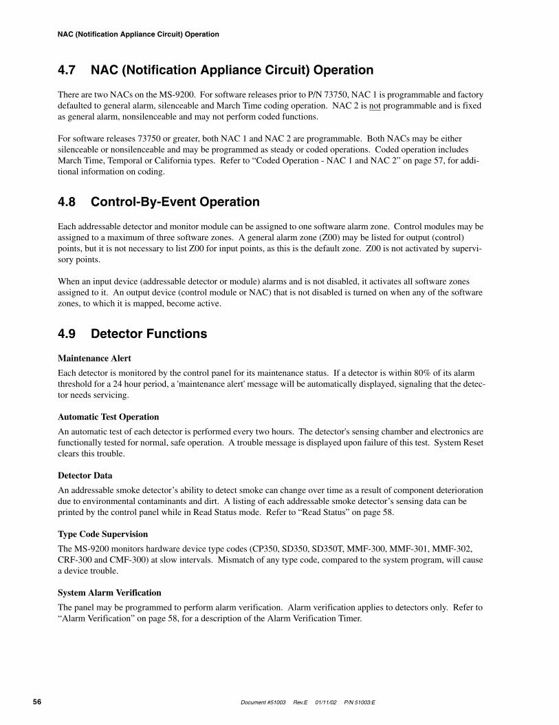
NAC (Notification Appliance Circuit) Operation
56 Document #51003 Rev.E 01/11/02 P/N 51003:E
4.7 NAC (Notification Appliance Circuit) Operation
There are two NACs on the MS-9200. For software releases prior to P/N 73750, NAC 1 is programmable and factory defaulted to general alarm, silenceable and March Time coding operation. NAC 2 is not programmable and is fixed as general alarm, nonsilenceable and may not perform coded functions.
For software releases 73750 or greater, both NAC 1 and NAC 2 are programmable. Both NACs may be either silenceable or nonsilenceable and may be programmed as steady or coded operations. Coded operation includes March Time, Temporal or California types. Refer to “Coded Operation - NAC 1 and NAC 2” on page 57, for addi-tional information on coding.
4.8 Control-By-Event Operation
Each addressable detector and monitor module can be assigned to one software alarm zone. Control modules may be assigned to a maximum of three software zones. A general alarm zone (Z00) may be listed for output (control) points, but it is not necessary to list Z00 for input points, as this is the default zone. Z00 is not activated by supervi-sory points.
When an input device (addressable detector or module) alarms and is not disabled, it activates all software zones assigned to it. An output device (control module or NAC) that is not disabled is turned on when any of the software zones, to which it is mapped, become active.
4.9 Detector Functions
Maintenance Alert
Each detector is monitored by the control panel for its maintenance status. If a detector is within 80% of its alarm threshold for a 24 hour period, a 'maintenance alert' message will be automatically displayed, signaling that the detec-tor needs servicing.
Automatic Test Operation
An automatic test of each detector is performed every two hours. The detector's sensing chamber and electronics are functionally tested for normal, safe operation. A trouble message is displayed upon failure of this test. System Reset clears this trouble.
Detector Data
An addressable smoke detector’s ability to detect smoke can change over time as a result of component deterioration due to environmental contaminants and dirt. A listing of each addressable smoke detector’s sensing data can be printed by the control panel while in Read Status mode. Refer to “Read Status” on page 58.
Type Code Supervision
The MS-9200 monitors hardware device type codes (CP350, SD350, SD350T, MMF-300, MMF-301, MMF-302, CRF-300 and CMF-300) at slow intervals. Mismatch of any type code, compared to the system program, will cause a device trouble.
System Alarm Verification
The panel may be programmed to perform alarm verification. Alarm verification applies to detectors only. Refer to “Alarm Verification” on page 58, for a description of the Alarm Verification Timer.
Document #51003 Rev.E 01/11/02 P/N 51003:E 57
Time Functions: Real-Time Clock
4.10 Time Functions: Real-Time Clock
The MS-9200 includes a crystal-based clock that provides time of day, date and day of week. Time is displayed as 12 hour time with month/day/year and is stored in RAM. If both AC and battery power are lost, the time must be reset.
4.11 Coded Operation - NAC 1 and NAC 2
Shown below are the pulse rate outputs via NAC 1 or NAC 2 when coded operation is selected. Note that software releases prior to P/N 73750 allow coding of only NAC 1. Releases 73750 or greater allow coded functions on both NAC 1 and NAC 2.
CONTINUOUS: No Pulse
MARCH TIME: Pulses at 120 ppm (pulses per minute)
TEMPORAL CODE: Pulses at ½ second On, ½ second Off, ½ second On, ½ second Off, ½ second On, 1½ seconds Off
CALIFORNIA CODE: 10 seconds On, 5 seconds Off
4.12 Presignal
Presignal is used to delay output activation (control modules and NACs) while allowing for visual verification by a person. Once a detector or monitor module triggers an alarm, the onboard piezo sounds immediately, but the Notifi-cation Appliance Circuits are not activated for 15 seconds. During this time, if the Acknowledge key is pressed, the piezo is silenced and the notification appliances will not activate for up to three minutes. After three minutes, the NACs will activate if the source of the alarm is not cleared. This does not affect monitor modules programmed as waterflow or supervisory. Presignal operation requires the approval of the local Authority Having Jurisdiction.
4.13 Special System Timers
4.13.1 Silence Inhibit Timer (None or 60 Seconds)
This option, if selected, prevents the Alarm Silence and Reset keys from functioning for 60 seconds after an initial alarm. A new alarm during the initial 60 seconds will not cause the timer to restart with a new 60 seconds. Silence Inhibit operation requires the approval of the local Authority Having Jurisdiction.
4.13.2 Auto-silence Timer (None or 10 Minutes)
If Auto-silence is selected, the notification appliances will be silenced automatically after ten minutes of activation. Pressing the Drill key will restart the timer with a new 10 minutes. Auto-silence operation requires the approval of the local Authority Having Jurisdiction.
4.13.3 Trouble Reminder
If selected, this feature causes a reminding 'beep' every 15 seconds during an alarm (after the Silence key is pressed) and every two minutes during a trouble condition (after the Acknowledge or Silence key is pressed). The 'beeps' from the onboard piezo sounder will occur until the alarm or fault is cleared.

�����������
� ���������������������������������������������������������������������������� ���������������� ����� ������������ ���
�������������� � ��� ��
��������������� �������������������������� ������ �������������� ���� ������������� ������� ��������
������� ����������� ��� ������� �������������������������� ������������ ���������� !����������"�����
#� ������� ������ ��#� �� ��$%��� ����� �� ���������������������&������������ ������������� ������
��������#����� ��������������������##� #���� ��#������������������������ ��� ���������� !����������'
��������� ���������������������������������� ���������� ��#� ������#���������������������������
�##� #���� ��#������������������������ ��� ���������� !������� ����� �������� ��������� ����������(��
�� ���� ����������������)����� ���������#����$%��� ���� ������ �*���������������������#������������ �
���������������� ������������������ �����
������������������ �� �������� ��
������������+������ ����� �� ��� ����# ������������� ����#�� ������������,��������������� ������� ��
��������� ������������������ ��
��#���# �������������������� �� ���������������� ������ -.�) ��� �'-�'.���*����������/������ ��#���
# ���������������� ���������������������# ����������������������������� ������������+�#� ���������
�������������������������#�������� !�"#�
���� �����������
������,0 �����������#� �������� ��,����$������������������ ����������� ��� ��#��������������������������
����� ������� ����������������� ������� ����������������#���������������� ����������#���������������,��'
���"�����������#������������#������ ���!�$������� ������#�
��� �����������
"���,����������� ���� �� ���&�����#���� ��������1,'23%%������ ������ �#� ������#� ��� ��������"���
,������� ����"���,������������������������� ��� ��#�������������� ���� �������������������� ���� ����
��������������������� �������"���,��������+���� �#������ ���� ��
%��&�!���������$
��� #��� ��#��������.��������������0 /���#������ ��4
�������������������
�� ��������������������������
������������� �� ����!�����!���������������"#�$������ �� ���"��$ "���"�������
�� ����!����������"� ��%�!��������������
�� �� ���������&��"#"�� "������ ����'���#"��� "���
�� �� ���(������ �������
�"##���� ��� �� �����������)�"��� "�� ��� �� ��*��&��"#"�� "���!��"��
1=PROGRAMMING2=RD STATUS 3=RD BAT

Document #51003 Rev.E 01/11/02 P/N 51003:E 59
Read Status
The operator presses '2' and the Read Status display shows:
From the display shown above, an operator may select one of the choices as listed below:
• To Display Point Status, the type of device to be read must first be identified by pressing the * key for a detec-tor or the # key for a module. The two-digit device address is keyed in next, followed by the Enter key
• To Display Zone status, press the * key then press the * key a second time. Next, key-in the zone number (1 - 56) and press Enter. The Up and Down arrow keys are used to view the next or previous zone
• To Display System Parameters, press the * key then press the * key again followed by Enter
• To Display Bell Circuit status, press the * key, followed by the # key and then the digit '1' or '2', followed by the Enter key
• To display the 500-event History file on the LCD, press the '1' key followed by the Enter key. The Up and Down arrow keys are used to step through the entries in the file
• To Print Program Contents and Current System Status or History File or addressable smoke Detector Data, press the '2' and then the Enter keys. A new menu appears which prompts the user to press '1' to print Pro-gram/Status, '2' to print History file or ‘3’ to print Detector Data.
During this and all subsequent operations except print operations, a two minute timer is started that will cause the panel to return to the previous display if no key is pressed within two minutes. Each key press restarts the two minute timer. A press of the left arrow (backspace) key deletes the previous entry. If there is no entry, it will cancel the Read Status operation and return to the previous display. System Reset will also cancel the Read Status operation.
Display Point
Display Point operations display addressable device status on the LCD display. After the status of the device is dis-played, the Up arrow key may be used to display the status of the next highest addressable device and the Down arrow key may be used to display the status of the previous addressable device. The sequence of point display is Detector points 01 - 99, Module points 01 - 99, NAC bell circuits 01 & 02, System Parameters and Zones 1 - 56.
A typical Read Status display is as follows:
In the preceding display:
✓ NORMAL is the present status (could be ALARM, TRBL_#, DISABL, etc.)
✓ SMOKE (DET) is the device type P indicates that this is a photoelectric detector (could be I if ionization or PULL BOX, HORN CKT, etc.) and 01 is the device address
✓ WEST HALLWAY is the custom label programmed for this device
✓ Z56 is the assigned software zone
If the point is not installed, a Read Status command will result in a NOT INSTALLED message on the display.
DISPLAY POINT=*/#,AAHISTORY=1 PRINT=2
NORMAL SMOKE DET P01WEST HALLWAY Z56

Read Status
60 Document #51003 Rev.E 01/11/02 P/N 51003:E
Read History
The MS-9200 has a 500-event history buffer. Stored events include Point Status, System Troubles, and Acknowl-edge/Step, Alarm Silence, Drill and System Reset key presses. All events are recorded with the time and date. His-tory events are stored in volatile memory, therefore, removal of primary AC power and secondary battery power will clear the history buffer. To clear the History file without removing power, see “Clear History” on page 49. To view events in the history file, use the Up and Down arrow keys to step through the events.
Pressing ‘2’ while viewing the Read Status screen will cause the following Print screen to be displayed.
Print Program/Status
All user programmed options, including device types, software zone assignments and system parameters, may be printed by pressing ‘1’ while viewing the Print screen. The printout also includes current system status. See “Printer/PC and Terminal Mode Annunciator Interface” on page 35, for instructions on connecting a printer.
Print History
The entire 500-event history file may be printed using the Print History feature by pressing ‘2’ while viewing the Print screen. Refer to “Printer/PC and Terminal Mode Annunciator Interface” on page 35, for instructions on con-necting a printer.
Print Detector Data
Each addressable smoke detector’s data, relating to its ability to detect smoke, can be printed by pressing ‘3’ for DET_DATA while viewing the Print screen. A printout similar to the following will be generated to an optional printer connected to the FACP.
The Chamber Reading should be within the indicated ranges for the following smoke detectors:
• SD350(T), D350P(R) and SD 300(T) Addressable Photoelectric Smoke Detectors: 405 - 2100 (obscuration of 1.00%/ft. to 3.66%/ft.)
• CP350 and CP300 Addressable Ionization Smoke Detectors: 750 - 2100 (obscuration of 0.50%/ft. to 1.44%/ft.)
If the addressable smoke detector’s Chamber Reading is not within the acceptable range, clean the detector and check the Chamber Reading again. If the reading is still not within the acceptable range, immediately replace the detector.
PRN PRGRAM/STATUS=1HISTORY=2 DET DATA=3
*************************************DETECTOR DATA************************************
DEVICE TYPE CHAMBER READING TIME/DATESMOKE DET P01 1420 03:52P Fri 01/19/01SMOKE DET P02 1362 03:52P Fri 01/19/01SMOKE DET I03 1452 03:52P Fri 01/19/01SMOKE DET I04 1350 03:52P Fri 01/19/01
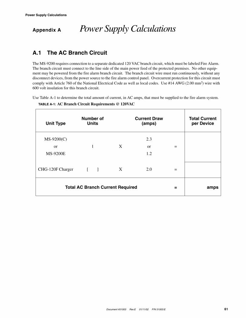
Document #51003 Rev.E 01/11/02 P/N 51003:E 61
Power Supply Calculations
Appendix A Power Supply Calculations
A.1 The AC Branch Circuit
The MS-9200 requires connection to a separate dedicated 120 VAC branch circuit, which must be labeled Fire Alarm. The branch circuit must connect to the line side of the main power feed of the protected premises. No other equip-ment may be powered from the fire alarm branch circuit. The branch circuit wire must run continuously, without any disconnect devices, from the power source to the fire alarm control panel. Overcurrent protection for this circuit must comply with Article 760 of the National Electrical Code as well as local codes. Use #14 AWG (2.00 mm2) wire with 600 volt insulation for this branch circuit.
Use Table A-1 to determine the total amount of current, in AC amps, that must be supplied to the fire alarm system.
TABLE A-1: AC Branch Circuit Requirements @ 120VAC
Unit TypeNumber of
UnitsCurrent Draw
(amps)Total Current
per Device
MS-9200(C)
or
MS-9200E
1 X
2.3
or
1.2
=
CHG-120F Charger [ ] X 2.0 =
Total AC Branch Current Required = amps

Power Supply Calculations
62 Document #51003 Rev.E 01/11/02 P/N 51003:E
A.2 The Main Power Supply
The MS-9200 provides filtered power for operating the fire alarm control panel, operating external devices and oper-ating the standby battery. The power for operating external devices is limited. Use Table A-2 (standby or nonalarm) and Table A-3 (alarm) to determine if external loading is within the capabilities of the MS-9200 power supply.
Concerning smoke detectors: refer to the manufacturer's data sheet packaged with each smoke detector to find the standby and alarm current draws to use in the following tables. Power detectors from TB4, Terminals 5 and 6.
Notes:1. TB4, Terminals 1 & 2; nonregulated 24 VDC, 2.5 amps2. TB4, Terminals 3 & 4; filtered 24 VDC +/-5% 120Hz ripple @ 10 mVRMS
3. TB4, Terminals 5 & 6; filtered 24 VDC +/-5% 120Hz ripple @ 10 mVRMS
4. TB4, Terminals 3 & 4; nonresettable auxiliary power, 300 mA5. TB4, Terminals 5 & 6; resettable smoke detector power, 300 mA6. Refer to Current Limitations on following page7. During AC loss, the LCD-40 backlight is extinguished to conserve power, reducing the standby current draw
from the batteries to 0.029 amps8. Maximum alarm current for each sounder base is 0.015 amps which must be supplied by aux. 24VDC source
TABLE A-2: Filtered Load in Standby - External Devices Connected to TB4 Only
Device Type # of Devices
Standby Current (amps)
Total Current (amps)
Main Circuit Board 1 X 0.08 = 0.08RTM-8F [ ] one max. X 0.009 =
ACM-8RF [ ] X 0.030 =ACM-16ATFACM-32AF
[ ] one max. X 0.04 =
AEM-16ATFAEM-32AF
[ ] X 0.002 =
AFM-16ATFAFM-32AF
[ ] X 0.04 =
AFM-16AF [ ] X 0.025 =411UD [ ] one max. X 0.100 =
UDACT-F [ ] one max. X 0.04 =LDM-32F [ ] X 0.04 =
LDM-E32F [ ] X 0.002 =LCD-40 Series [ ] X 0.0647 =
4-Wire Smoke Detector [ ] X [ ] =4-Wire Smoke Detector [ ] X [ ] =
Power Supervision Relay [ ] X 0.025 =CP350 [ ] X 0.00030 =SD350 [ ] X 0.00030 =
SD350T [ ] X 0.00030 =D350P [ ] X 0.00030 =
D350RP [ ] X 0.00030 =B501BH & B501BHT8 [ ] X 0.00100 =
B224RB Relay Base [ ] X 0.00050 =B224BI Isolator Base [ ] X 0.00045 =
MMF-300 [ ] X 0.00040 =MDF-300 [ ] X 0.00040 =MMF-301 [ ] X 0.000375 =MMF-302 [ ] X 0.00027 =BG-12LX [ ] X 0.00020 =CMF-300 [ ] X 0.00039 =CRF-300 [ ] X 0.00027 =
I300 [ ] X 0.00040 =Auxiliary Devices Powered
from TB4[ ] X [ ] =
Sum Column for Standby Load =
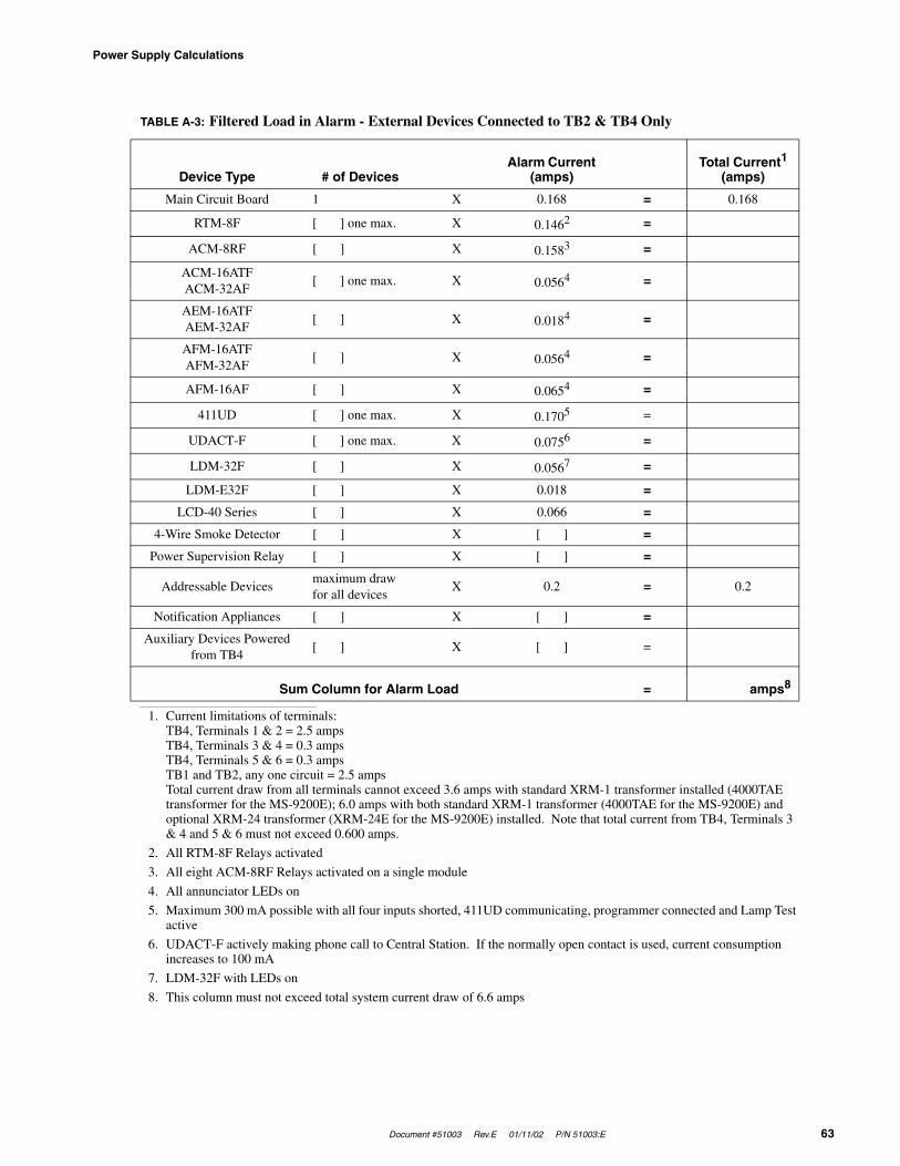
Document #51003 Rev.E 01/11/02 P/N 51003:E 63
Power Supply Calculations
TABLE A-3: Filtered Load in Alarm - External Devices Connected to TB2 & TB4 Only
Device Type # of DevicesAlarm Current
(amps)Total Current1
(amps)
1. Current limitations of terminals:TB4, Terminals 1 & 2 = 2.5 ampsTB4, Terminals 3 & 4 = 0.3 ampsTB4, Terminals 5 & 6 = 0.3 ampsTB1 and TB2, any one circuit = 2.5 ampsTotal current draw from all terminals cannot exceed 3.6 amps with standard XRM-1 transformer installed (4000TAE transformer for the MS-9200E); 6.0 amps with both standard XRM-1 transformer (4000TAE for the MS-9200E) and optional XRM-24 transformer (XRM-24E for the MS-9200E) installed. Note that total current from TB4, Terminals 3 & 4 and 5 & 6 must not exceed 0.600 amps.
Main Circuit Board 1 X 0.168 = 0.168
RTM-8F [ ] one max. X 0.1462
2. All RTM-8F Relays activated
=
ACM-8RF [ ] X 0.1583
3. All eight ACM-8RF Relays activated on a single module
=
ACM-16ATFACM-32AF
[ ] one max. X 0.0564
4. All annunciator LEDs on
=
AEM-16ATFAEM-32AF
[ ] X 0.0184 =
AFM-16ATFAFM-32AF
[ ] X 0.0564 =
AFM-16AF [ ] X 0.0654 =
411UD [ ] one max. X 0.1705
5. Maximum 300 mA possible with all four inputs shorted, 411UD communicating, programmer connected and Lamp Test active
=
UDACT-F [ ] one max. X 0.0756
6. UDACT-F actively making phone call to Central Station. If the normally open contact is used, current consumption increases to 100 mA
=
LDM-32F [ ] X 0.0567
7. LDM-32F with LEDs on
=
LDM-E32F [ ] X 0.018 =
LCD-40 Series [ ] X 0.066 =
4-Wire Smoke Detector [ ] X [ ] =
Power Supervision Relay [ ] X [ ] =
Addressable Devicesmaximum draw for all devices
X 0.2 = 0.2
Notification Appliances [ ] X [ ] =
Auxiliary Devices Powered from TB4
[ ] X [ ] =
Sum Column for Alarm Load = amps8
8. This column must not exceed total system current draw of 6.6 amps
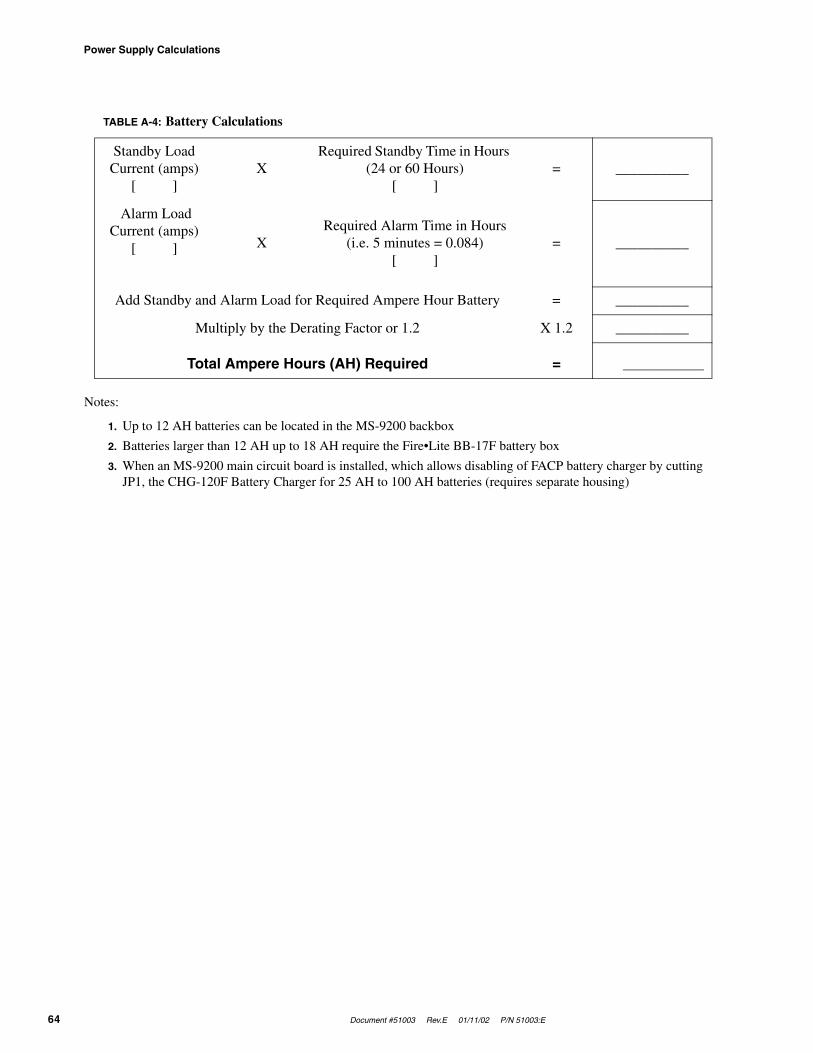
Power Supply Calculations
64 Document #51003 Rev.E 01/11/02 P/N 51003:E
Notes:
1. Up to 12 AH batteries can be located in the MS-9200 backbox
2. Batteries larger than 12 AH up to 18 AH require the Fire•Lite BB-17F battery box
3. When an MS-9200 main circuit board is installed, which allows disabling of FACP battery charger by cutting JP1, the CHG-120F Battery Charger for 25 AH to 100 AH batteries (requires separate housing)
TABLE A-4: Battery Calculations
Standby Load Current (amps)
[ ]X
Required Standby Time in Hours (24 or 60 Hours)
[ ]= __________
Alarm Load Current (amps)
[ ] XRequired Alarm Time in Hours
(i.e. 5 minutes = 0.084)[ ]
= __________
Add Standby and Alarm Load for Required Ampere Hour Battery = __________
Multiply by the Derating Factor or 1.2 X 1.2 __________
Total Ampere Hours (AH) Required = __________

Document #51003 Rev.E 01/11/02 P/N 51003:E 65
Software Zones
Appendix B Software Zones
Setup and configuration of an addressable system is quite different than a conventional system. In a conventional system, assignment of input devices (smoke detectors, pull stations, heat detectors, etc.) to zones is straight forward. Wiring is direct from clearly marked panel terminals to any device assigned to a particular zone. Connection of out-put devices (horns, bells, strobes, etc.) in a conventional system is done by direct wiring of the output device to termi-nals marked 'bell'.
With addressable systems, the same pair of wires is used to connect to all addressable input and output devices. Com-munications between the panel and all addressable devices takes place over one pair of wires originating from the control panel. Software programming is used to configure the system, versus direct wiring. Zone assignment is cre-ated via software means, hence the term 'software zones'.
Setup of an MS-9200 software zone is straightforward. Any zone may have a minimum of one and a maximum of 99 addressable input devices. Each detector is automatically assigned to a general alarm output. A zone may also have a minimum of one and a maximum of 99 addressable output devices.
Use the charts on the following pages to help in 'zoning' the system. Note that monitor and control modules make up one group of 99 addresses. It is critical that addresses of detectors are not duplicated and that monitor and control module addresses are not duplicated.
In the example on the following page:
• Zone 1 has the following addressable devices assigned to it:
✓ SD350 photoelectric detectors with addresses '01' and '02'
✓ MMF-300 monitor module with address '01'
✓ CMF-300 control modules with addresses '03', '04' and '05'
• Zone 2 has the following addressable devices assigned to it:
✓ CP350 ionization detectors with addresses '03' and '04'
✓ MMF-301 monitor module with address '02'
✓ CMF-300 control modules with addresses '03', '06' and '07'
• Zone 3 has the following addressable devices assigned to it:
✓ SD350 photoelectric detectors with addresses '05' and '06'
✓ CP350 ionization detector with address '07'
✓ CMF-300 control modules with addresses '03', '08' and '09'
The example points out some of the key assignment features of the MS-9200. Addresses of detectors are not dupli-cated. Addresses of monitor and control modules are not duplicated. The control module at address '03' is assigned to the maximum three software zones (providing for floor above and floor below). Detectors and monitor modules are assigned to one software zone.
Be careful to properly plan the installation prior to installing any devices.
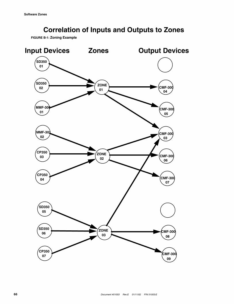
Software Zones
66 Document #51003 Rev.E 01/11/02 P/N 51003:E
Correlation of Inputs and Outputs to ZonesFIGURE B-1: Zoning Example
SD350 01
SD350 02
MMF-300 01
CMF-300 05
CMF-300 04
ZONE 01
MMF-301 02
CP350 03
CP350 04 CMF-300
07
CMF-300 06
CMF-300 03
ZONE 02
SD350 05
SD350 06
CP350 07 CMF-300
09
CMF-300 08
ZONE 03
Input Devices Zones Output Devices
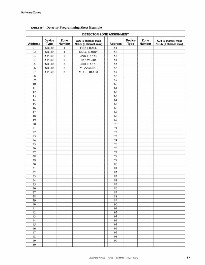
Document #51003 Rev.E 01/11/02 P/N 51003:E 67
Software Zones
TABLE B-1: Detector Programming Sheet Example
DETECTOR ZONE ASSIGNMENT
AddressDevice Type
Zone Number
ADJ (5 charact. max)NOUN (9 charact. max) Address
Device Type
Zone Number
ADJ (5 charact. max)NOUN (9 charact. max)
01 SD350 1 FIRST HALL 5102 SD350 1 ELEV. LOBBY 5203 CP350 2 2ND FLOOR 5304 CP350 2 ROOM 210 5405 SD350 3 3RD FLOOR 5506 SD350 3 MEZZANINE 5607 CP350 3 MECH. ROOM 5708 5809 5910 6011 6112 6213 6314 6415 6516 6617 6718 6819 6920 7021 7122 7223 7324 7425 7526 7627 7728 7829 7930 8031 8132 8233 8334 8435 8536 8637 8738 8839 8940 9041 9142 9243 9344 9445 9546 9647 9748 9849 9950
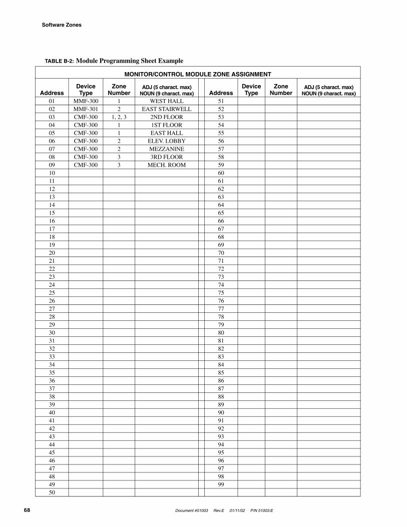
Software Zones
68 Document #51003 Rev.E 01/11/02 P/N 51003:E
TABLE B-2: Module Programming Sheet Example
MONITOR/CONTROL MODULE ZONE ASSIGNMENT
AddressDevice Type
Zone Number
ADJ (5 charact. max)NOUN (9 charact. max) Address
Device Type
Zone Number
ADJ (5 charact. max)NOUN (9 charact. max)
01 MMF-300 1 WEST HALL 5102 MMF-301 2 EAST STAIRWELL 5203 CMF-300 1, 2, 3 2ND FLOOR 5304 CMF-300 1 1ST FLOOR 5405 CMF-300 1 EAST HALL 5506 CMF-300 2 ELEV. LOBBY 5607 CMF-300 2 MEZZANINE 5708 CMF-300 3 3RD FLOOR 5809 CMF-300 3 MECH. ROOM 5910 6011 6112 6213 6314 6415 6516 6617 6718 6819 6920 7021 7122 7223 7324 7425 7526 7627 7728 7829 7930 8031 8132 8233 8334 8435 8536 8637 8738 8839 8940 9041 9142 9243 9344 9445 9546 9647 9748 9849 9950
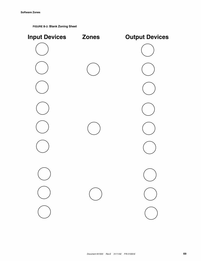
Document #51003 Rev.E 01/11/02 P/N 51003:E 69
Software Zones
FIGURE B-2: Blank Zoning Sheet
Input Devices Zones Output Devices

Software Zones
70 Document #51003 Rev.E 01/11/02 P/N 51003:E
TABLE B-3: Blank Detector Programming Sheet
DETECTOR ZONE ASSIGNMENT
AddressDevice Type
Zone Number
ADJ (5 charact. max)NOUN (9 charact. max) Address
Device Type
Zone Number
ADJ (5 charact. max)NOUN (9 charact. max)
01 5102 5203 5304 5405 5506 5607 5708 5809 5910 6011 6112 6213 6314 6415 6516 6617 6718 6819 6920 7021 7122 7223 7324 7425 7526 7627 7728 7829 7930 8031 8132 8233 8334 8435 8536 8637 8738 8839 8940 9041 9142 9243 9344 9445 9546 9647 9748 9849 9950
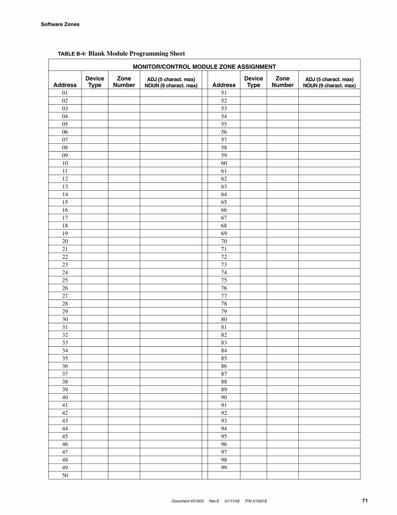
Document #51003 Rev.E 01/11/02 P/N 51003:E 71
Software Zones
TABLE B-4: Blank Module Programming Sheet
MONITOR/CONTROL MODULE ZONE ASSIGNMENT
AddressDevice Type
Zone Number
ADJ (5 charact. max)NOUN (9 charact. max) Address
Device Type
Zone Number
ADJ (5 charact. max)NOUN (9 charact. max)
01 5102 5203 5304 5405 5506 5607 5708 5809 5910 6011 6112 6213 6314 6415 6516 6617 6718 6819 6920 7021 7122 7223 7324 7425 7526 7627 7728 7829 7930 8031 8132 8233 8334 8435 8536 8637 8738 8839 8940 9041 9142 9243 9344 9445 9546 9647 9748 9849 9950
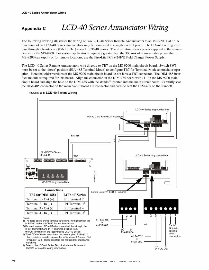
LCD-40 Series Annunciator Wiring
72 Document #51003 Rev.E 01/11/02 P/N 51003:E
Appendix C LCD-40 Series Annunciator Wiring
The following drawing illustrates the wiring of two LCD-40 Series Remote Annunciators to an MS-9200 FACP. A maximum of 32 LCD-40 Series annunciators may be connected to a single control panel. The EIA-485 wiring must pass through a ferrite core (P/N FBD-1) in each LCD-40 Series. The illustration shows power supplied to the annun-ciators by the MS-9200. For system applications requiring greater than the 300 mA of nonresettable power the MS-9200 can supply or for remote locations, use the Fire•Lite FCPS-24F/E Field Charger Power Supply.
The LCD-40 Series Remote Annunciators wire directly to TB7 on the MS-9200 main circuit board. Switch SW3 must be set to the ‘down’ position (EIA-485 Terminal Mode) to configure TB7 for Terminal Mode annunciator oper-ation. Note that older versions of the MS-9200 main circuit board do not have a TB7 connector. The DIM-485 inter-face module is required for this board. Align the connector on the DIM-485 board with J11 on the MS-9200 main circuit board and align the hole on the DIM-485 with the standoff inserted into the main circuit board. Carefully seat the DIM-485 connector on the main circuit board J11 connector and press to seat the DIM-485 on the standoff.
24V UNREG 24V NONRS 24V RST BELL 2 POWER BELL 1 POWER SUPV ALARM TROUBLE PC/PRINTERTERM COMM+ - + - + - B+ A+ A- B- B+ A+ A- B- NO C NO NC C NO NC C A B B+ A+ B- A- 1 COMM 2
ACS SHIELD SLC SLCOUT+ IN+ OUT- IN-T
B4
TB2
TB1
TB3
TB7
TB5
TB6
FIGURE C-1: LCD-40 Series Wiring
LCD-40 Series in grounded box
LCD-40 Series in grounded box
Ferrite Core P/N FBD-1 Required
Ferrite Core P/N FBD-1 Required
EIA-485
TB7
24 VDC TB4 Terms 3(+) & 4(-)
MS-9200 in grounded box
Earth Ground- optional shield connection
(+) (-) 24 VDC Out
n/c
(+) 24 VDC IN(-) 24 VDC
(+) EIA-485 IN(-) EIA-485
(+) (-) EIA-485 Out
Notes:1) The table above shows terminal to terminal wiring between the MS-9200 and one LCD-40 Series Annunciator2) If more than one LCD-40 Series is installed, the wiring to the In (+) Terminal 2 and In (-) Terminal 4 will be from the Out terminals of the last installed LCD-40 Series3) The LCD-40 Series must have the two supplied R120 (120 ohm) resistors installed across the In Terminals 2 & 4 and Out Terminals 1 & 3. These resistors are required for impedance matching4) Refer to the LCD-40 Series Technical Manual Document #50327 for detailed wiring information.
ConnectionsTB7 (or DIM-485) LCD-403 Series
Terminal 1 - Out (+) P1 Terminal 2Terminal 2 - In (+) P1 Terminal 12
Terminal 3 - Out (-) P1 Terminal 4Terminal 4 - In (+) P1 Terminal 32
9200
lcd4
.cdr
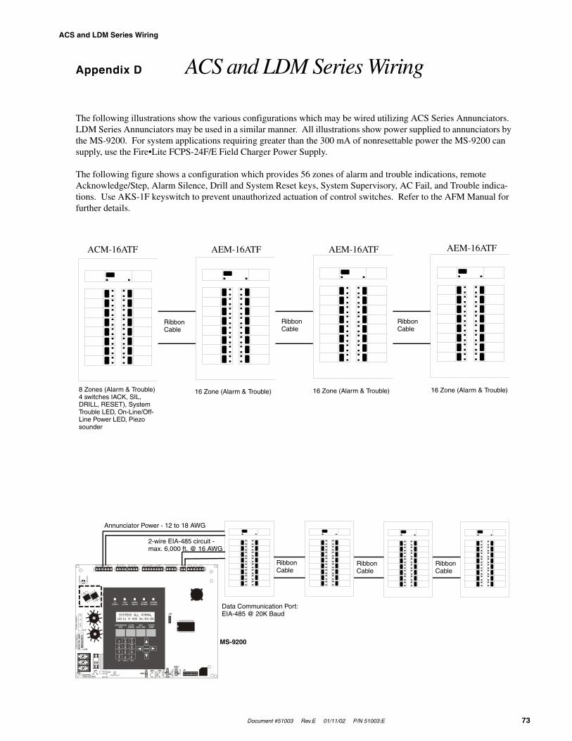
Document #51003 Rev.E 01/11/02 P/N 51003:E 73
ACS and LDM Series Wiring
Appendix D ACS and LDM Series Wiring
The following illustrations show the various configurations which may be wired utilizing ACS Series Annunciators. LDM Series Annunciators may be used in a similar manner. All illustrations show power supplied to annunciators by the MS-9200. For system applications requiring greater than the 300 mA of nonresettable power the MS-9200 can supply, use the Fire•Lite FCPS-24F/E Field Charger Power Supply.
The following figure shows a configuration which provides 56 zones of alarm and trouble indications, remote Acknowledge/Step, Alarm Silence, Drill and System Reset keys, System Supervisory, AC Fail, and Trouble indica-tions. Use AKS-1F keyswitch to prevent unauthorized actuation of control switches. Refer to the AFM Manual for further details.
24V UNREG 24V NONRS 24V RST BELL 2 POWER BELL 1 POWER SUPV ALARM TROUBLE PC/PRINTER TERM COMM
GN
D F
AULT
DISA
BLE
TRAN
SFO
RM
ER 1
TRAN
SFO
RM
ER 2
- +BATTERY
RS-
232
PC/P
RIN
TER
RS-
485
TER
M. M
OD
E
TRO
UBL
E
+ - + - + - B+ A+ A- B- B+ A+ A- B- NO C NO NC C NO NC C A B B+ A+ B- A- 1 COMM 2ACS SHIELD SLC SLC
OUT+ IN+ OUT- IN-TB4
TB2
TB1
TB3
TB7
TB5
TB6
J16
J6JP3JP1
CAUTIONHIGH VOLTAGE
J3TB8
J19
J17
JP4SW1
SW3
SW2
CA
UTIO
N!
HIGH
VOLTA
GE
GNDFAULT
ACM-16ATF AEM-16ATF AEM-16ATF AEM-16ATF
Ribbon Cable
Ribbon Cable
Ribbon Cable
8 Zones (Alarm & Trouble)4 switches IACK, SIL, DRILL, RESET), System Trouble LED, On-Line/Off-Line Power LED, Piezo sounder
16 Zone (Alarm & Trouble) 16 Zone (Alarm & Trouble) 16 Zone (Alarm & Trouble)
Ribbon Cable
Ribbon Cable
Ribbon Cable
Annunciator Power - 12 to 18 AWG
2-wire EIA-485 circuit - max. 6,000 ft. @ 16 AWG
MS-9200
Data Communication Port: EIA-485 @ 20K Baud

ACS and LDM Series Wiring
74 Document #51003 Rev.E 01/11/02 P/N 51003:E
The following configuration provides 56 zones of alarm indication, a System Trouble LED, an On Line/Power LED, local piezo sounder and a local Silence/Acknowledge switch.
The following configuration provides 16 alarm and trouble LEDs, System Trouble LED, On Line/Power LED, local Silence/Acknowledge, Drill and Reset remote switches and piezo sounder. Only one per system.
The following configuration provides 32 alarm LEDs, On Line/Power LED, System Trouble LED and local Silence/Acknowledge switch. Only one per system.
24V UNREG 24V NONRS 24V RST BELL 2 POWER BELL 1 POWER SUPV ALARM TROUBLE PC/PRINTER TERM COMM+ - + - + - B+ A+ A- B- B+ A+ A- B- NO C NO NC C NO NC C A B B+ A+ B- A- 1 COMM 2
ACS SHIELD SLC SLCOUT+ IN+ OUT- IN-
TB4
TB2
TB1
TB3
TB7
TB5
TB6
J16
ACM-32AF AEM-32AF
Ribbon Cable
MS-9200
24V UNREG 24V NONRS 24V RST BELL 2 POWER BELL 1 POWER SUPV ALARM TROUBLE PC/PRINTER TERM COMM+ - + - + - B+ A+ A- B- B+ A+ A- B- NO C NO NC C NO NC C A B B+ A+ B- A- 1 COMM 2
ACS SHIELD SLC SLCOUT+ IN+ OUT- IN-
TB4
TB2
TB1
TB3
TB7
TB5
TB6
J16
MS-9200
AFM-16ATF
24V UNREG 24V NONRS 24V RST BELL 2 POWER BELL 1 POWER SUPV ALARM TROUBLE PC/PRINTER TERM COMM+ - + - + - B+ A+ A- B- B+ A+ A- B- NO C NO NC C NO NC C A B B+ A+ B- A- 1 COMM 2
ACS SHIELD SLC SLCOUT+ IN+ OUT- IN-
TB4
TB2
TB1
TB3
TB7
TB5
TB6
J16
AFM-32AF
MS-9200
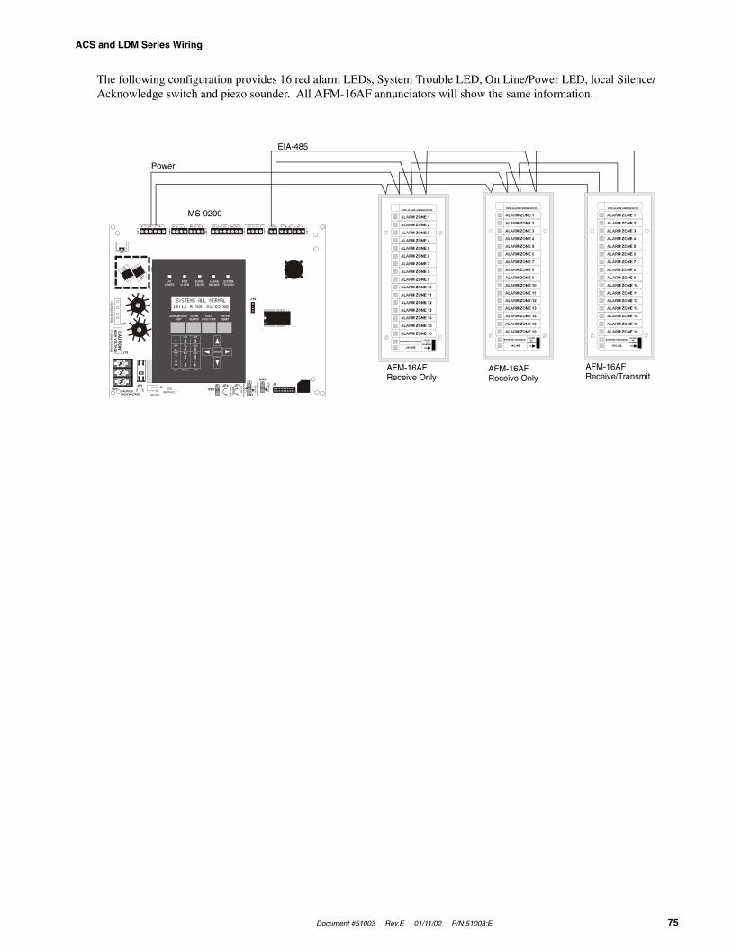
Document #51003 Rev.E 01/11/02 P/N 51003:E 75
ACS and LDM Series Wiring
The following configuration provides 16 red alarm LEDs, System Trouble LED, On Line/Power LED, local Silence/Acknowledge switch and piezo sounder. All AFM-16AF annunciators will show the same information.
24V UNREG 24V NONRS 24V RST BELL 2 POWER BELL 1 POWER SUPV ALARM TROUBLE PC/PRINTER TERM COMM
GN
D F
AULT
DIS
ABLE
TRAN
SFO
RM
ER 1
TRAN
SFO
RM
ER 2
- +BATTERY
RS-
232
PC/P
RIN
TER
RS-4
85TE
RM
. MO
DE
TRO
UBLE
+ - + - + - B+ A+ A- B- B+ A+ A- B- NO C NO NC C NO NC C A B B+ A+ B- A- 1 COMM 2ACS SHIELD SLC SLC
OUT+ IN+ OUT- IN-TB4
TB2
TB1
TB3
TB7
TB5
TB6
J16
J6JP3JP1CAUTIONHIGH VOLTAGE
J3TB8
J19
J17
JP4SW1
SW3
SW2
CA
UTIO
N!H
IGH VO
LTAG
E
GNDFAULT
EIA-485
Power
MS-9200
AFM-16AFReceive Only
AFM-16AFReceive Only
AFM-16AFReceive/Transmit
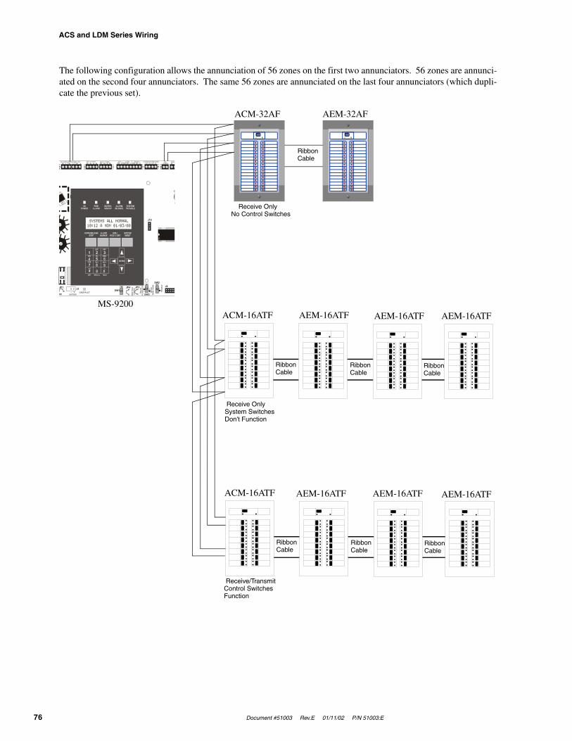
ACS and LDM Series Wiring
76 Document #51003 Rev.E 01/11/02 P/N 51003:E
The following configuration allows the annunciation of 56 zones on the first two annunciators. 56 zones are annunci-ated on the second four annunciators. The same 56 zones are annunciated on the last four annunciators (which dupli-cate the previous set).
24V UNREG 24V NONRS 24V RST BELL 2 POWER BELL 1 POWER SUPV ALARM TROUBLE PC/PRINTER TERM COMM
GN
D F
AULT
DIS
ABLE
- +BATTERY
RS-
232
PC/P
RIN
TER
RS-4
85TE
RM
. MO
DE
TRO
UBL
E+ - + - + - B+ A+ A- B- B+ A+ A- B- NO C NO NC C NO NC C A B B+ A+ B- A- 1 COMM 2
ACS SHIELD SLC SLCOUT+ IN+ OUT- IN-
TB4
TB2
TB1
TB3
TB7
TB5
TB6
J16
J6JP3JP1
GE
J3 JP4SW1
SW3
SW2
GNDFAULT
Ribbon Cable
Ribbon Cable
Ribbon Cable
ACM-32AF AEM-32AF
Ribbon Cable
MS-9200
Ribbon Cable
Ribbon Cable
Ribbon Cable
ACM-16ATF AEM-16ATF AEM-16ATF AEM-16ATF
ACM-16ATF AEM-16ATF AEM-16ATF AEM-16ATF
Receive OnlyNo Control Switches
Receive OnlySystem Switches Don't Function
Receive/TransmitControl Switches Function

Document #51003 Rev.E 01/11/02 P/N 51003:E 77
NFPA Standard-Specific Requirements
Appendix E NFPA Standard-Specific Requirements
The Fire•Lite MS-9200 has been designed for use in commercial, industrial and institutional applications and meets the requirements for service under the National Fire Protection Association (NFPA) Standards outlined in this Appen-dix. The minimum system components required for compliance with the appropriate NFPA standard are listed below:
MS-9200 Control Panel
Contains the main control board, cabinet (backbox and door), main power supply transformer and power supply.
Batteries
Refer to “Power Supply Calculations” on page 61, for Standby Power Requirements.
Initiating Devices
Connected to one of the control panel's Initiating Device Circuits.
Notification Appliances
Connected to the control panel's Notification Appliance Circuit via a control module.
The following additional equipment if needed for compliance with the NFPA 72 standards listed below:
NFPA 72 National Fire Alarm Standards for:
Fire Alarm Systems for Central Station Service (Protected Premises Unit) and Remote Station Service requires:
MS-5012 for connection to a compatible listed Central Station DACR or Protected Premises Receiv-ing Unit. This unit must be installed as outlined in Figure E-1, “Central Station Service Using MS-5012,” on page 78.
OR
UDACT-F may be installed as illustrated in Refer to Figure 2-11, “UDACT-F Mounting to MS-9200,” on page 30 and Figure 2-12, “External UDACT-F Mounting in ABS-8RF,” on page 31.
OR
411UD may be installed as illustrated Figure E-2, “Fire•Lite MS-9200 Connection to 411-UD,” on page 79.
NFPA 72 Auxiliary Fire Alarm System
RTM-8F Relay/Transmitter Module for connection to a compatible listed Local Energy Municipal Box. This unit must be installed as outlined in Figure E-3, “Municipal Box Connected to RTM-8F Relay Transmitter Module,” on page 80.
NFPA 72 Remote Station Fire Alarm System
RTM-8F Relay/Transmitter Module for connection to the Fire•Lite RS82 Remote Station Receiver. See Figure E-4, “Remote Station Connection Using RTM-8F Module,” on page 81, for installation instructions for this unit.
NFPA 72 Proprietary Fire Alarm System
MS-9200 Alarm, Trouble and Supervisory contacts connected to Transmitter(s). See Figure E-5, “Proprietary Protec-tive Signaling System,” on page 82, for installation instructions for this unit.
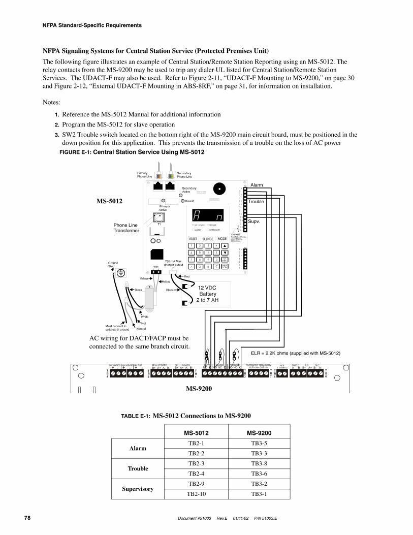
NFPA Standard-Specific Requirements
78 Document #51003 Rev.E 01/11/02 P/N 51003:E
NFPA Signaling Systems for Central Station Service (Protected Premises Unit)
The following figure illustrates an example of Central Station/Remote Station Reporting using an MS-5012. The relay contacts from the MS-9200 may be used to trip any dialer UL listed for Central Station/Remote Station Services. The UDACT-F may also be used. Refer to Figure 2-11, “UDACT-F Mounting to MS-9200,” on page 30 and Figure 2-12, “External UDACT-F Mounting in ABS-8RF,” on page 31, for information on installation.
Notes:
1. Reference the MS-5012 Manual for additional information
2. Program the MS-5012 for slave operation
3. SW2 Trouble switch located on the bottom right of the MS-9200 main circuit board, must be positioned in the down position for this application. This prevents the transmission of a trouble on the loss of AC power
TABLE E-1: MS-5012 Connections to MS-9200
MS-5012 MS-9200
AlarmTB2-1 TB3-5
TB2-2 TB3-3
TroubleTB2-3 TB3-8
TB2-4 TB3-6
SupervisoryTB2-9 TB3-2
TB2-10 TB3-1
24V UNREG 24V NONRS 24V RST BELL 2 POWER BELL 1 POWER SUPV ALARM TROUBLE PC/PRINTER TERM COMM+ - + - + - B+ A+ A- B- B+ A+ A- B- NO C NO NC C NO NC C A B B+ A+ B- A- 1 COMM 2
ACS SHIELD SLC SLCOUT+ IN+ OUT- IN-
TB4
TB2
TB1
TB3
TB7
TB5
TB6
FIGURE E-1: Central Station Service Using MS-5012
ELR = 2.2K ohms (supplied with MS-5012)
AC wiring for DACT/FACP must be connected to the same branch circuit.
MS-9200
MS-5012
Phone Line Transformer
Alarm
Trouble
Supv.
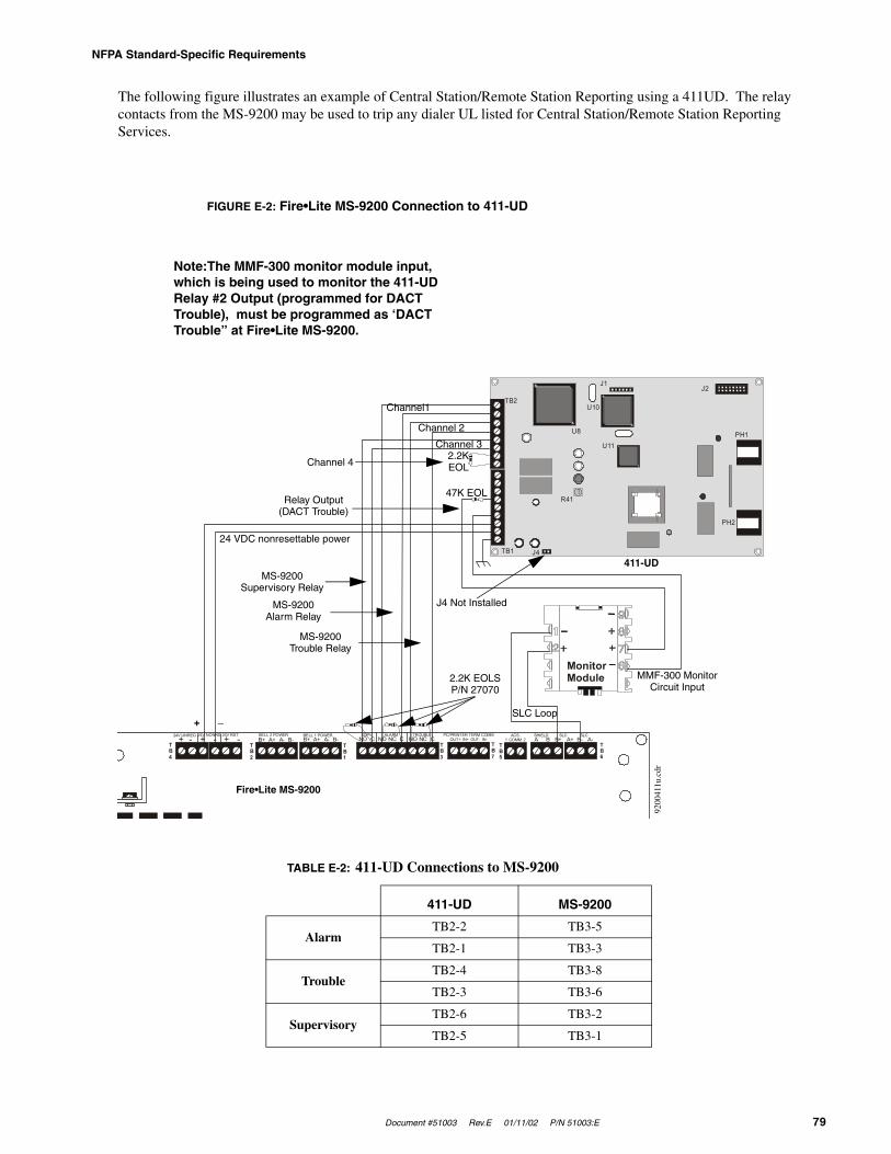
Document #51003 Rev.E 01/11/02 P/N 51003:E 79
NFPA Standard-Specific Requirements
The following figure illustrates an example of Central Station/Remote Station Reporting using a 411UD. The relay contacts from the MS-9200 may be used to trip any dialer UL listed for Central Station/Remote Station Reporting Services.
TABLE E-2: 411-UD Connections to MS-9200
411-UD MS-9200
AlarmTB2-2 TB3-5
TB2-1 TB3-3
TroubleTB2-4 TB3-8
TB2-3 TB3-6
SupervisoryTB2-6 TB3-2
TB2-5 TB3-1
24V UNREG 24V NONRS 24V RST BELL 2 POWER BELL 1 POWER SUPV ALARM TROUBLE PC/PRINTER TERM COMM+ - + - + - B+ A+ A- B- B+ A+ A- B- NO C NO NC C NO NC C A B B+ A+ B- A- 1 COMM 2ACS SHIELD SLC SLC
OUT+ IN+ OUT- IN-TB4
TB2
TB1
TB3
TB7
TB5
TB6
TB2
TB1
U8
U10
U11
J1J2
J4
PH1
R41
PH2
MonitorModule
FIGURE E-2: Fire•Lite MS-9200 Connection to 411-UD
Note:The MMF-300 monitor module input, which is being used to monitor the 411-UD Relay #2 Output (programmed for DACT Trouble), must be programmed as ‘DACT Trouble” at Fire•Lite MS-9200.
Channel1
Channel 2
Channel 3
Channel 42.2KEOL
Relay Output(DACT Trouble)
47K EOL
24 VDC nonresettable power
MS-9200Supervisory Relay
MS-9200Alarm Relay
MS-9200Trouble Relay
2.2K EOLSP/N 27070
J4 Not Installed
411-UD
MMF-300 MonitorCircuit Input
SLC Loop+ _
Fire•Lite MS-9200
9200
411u
.cdr
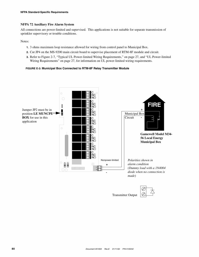
NFPA Standard-Specific Requirements
80 Document #51003 Rev.E 01/11/02 P/N 51003:E
NFPA 72 Auxiliary Fire Alarm System
All connections are power-limited and supervised. This applications is not suitable for separate transmission of sprinkler supervisory or trouble conditions.
Notes:
1. 3 ohms maximum loop resistance allowed for wiring from control panel to Municipal Box.
2. Cut JP4 on the MS-9200 main circuit board to supervise placement of RTM-8F module and circuit.
3. Refer to Figure 2-7, “Typical UL Power-limited Wiring Requirements,” on page 27, and “UL Power-limited Wiring Requirements” on page 27, for information on UL power-limited wiring requirements.
FIGURE E-3: Municipal Box Connected to RTM-8F Relay Transmitter Module
FIRE
Gamewell Model M34-56 Local Energy Municipal Box
Polarities shown in alarm condition(Dummy load with a 1N4004 diode when no connection is made)
Transmitter Output
+
-
Nonpower-limited
Municipal Box Circuit
+
-
Jumper JP2 must be in position LE MUNCPL BOX for use in this application
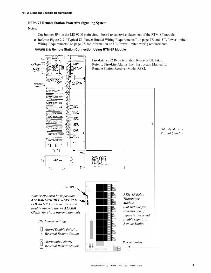
Document #51003 Rev.E 01/11/02 P/N 51003:E 81
NFPA Standard-Specific Requirements
NFPA 72 Remote Station Protective Signaling System
Notes:
1. Cut Jumper JP4 on the MS-9200 main circuit board to supervise placement of the RTM-8F module.
2. Refer to Figure 2-7, “Typical UL Power-limited Wiring Requirements,” on page 27, and “UL Power-limited Wiring Requirements” on page 27, for information on UL Power-limited wiring requirements.
Fire•Lite RS82 Remote Station Receiver UL listed.Refer to Fire•Lite Alarms, Inc., Instruction Manual for Remote Station Receiver Model RS82.
+ -
Polarity Shown is Normal Standby
RTM-8F Relay Transmitter Module (not suitable for transmission of separate alarm and trouble signals to Remote Station)
Cut JP1
Jumper JP2 must be in position ALARM/TROUBLE REVERSE POLARITY for use in alarm and trouble transmission or ALARM ONLY for alarm transmission only
JP2 Jumper Settings:
Alarm/Trouble Polarity Reversal Remote Station
Alarm only Polarity Reversal Remote Station +
-
Power-limited
FIGURE E-4: Remote Station Connection Using RTM-8F Module
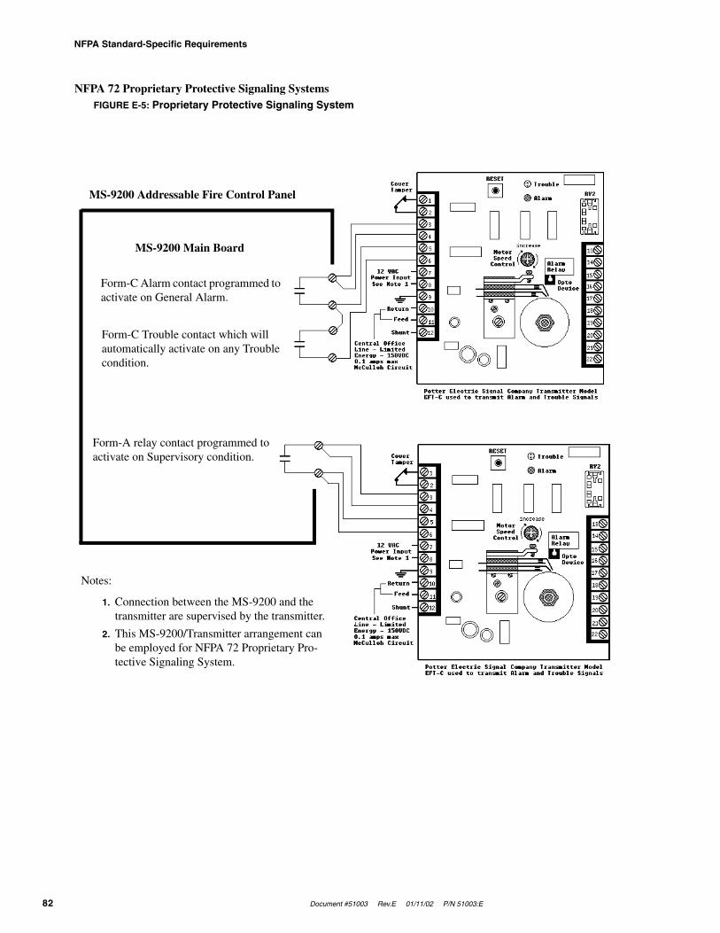
NFPA Standard-Specific Requirements
82 Document #51003 Rev.E 01/11/02 P/N 51003:E
NFPA 72 Proprietary Protective Signaling SystemsFIGURE E-5: Proprietary Protective Signaling System
Form-A relay contact programmed to activate on Supervisory condition.
Form-C Trouble contact which will automatically activate on any Trouble condition.
Form-C Alarm contact programmed to activate on General Alarm.
MS-9200 Main Board
MS-9200 Addressable Fire Control Panel
Notes:
1. Connection between the MS-9200 and the transmitter are supervised by the transmitter.
2. This MS-9200/Transmitter arrangement can be employed for NFPA 72 Proprietary Pro-tective Signaling System.
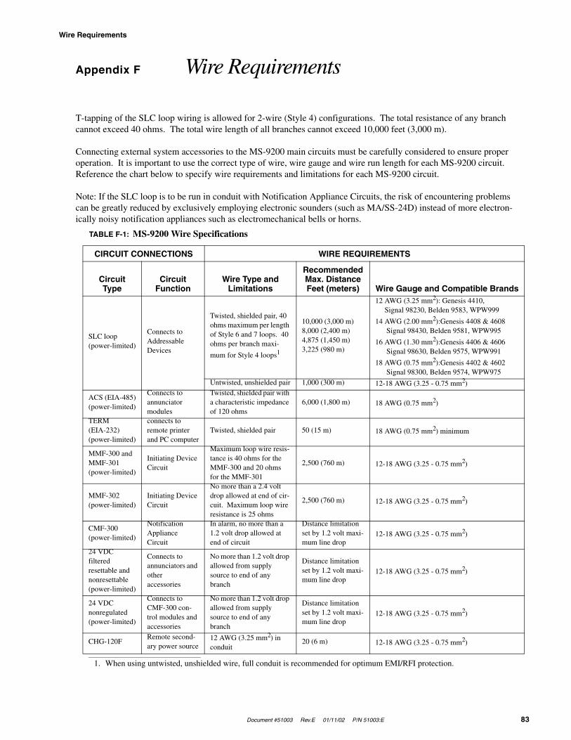
Document #51003 Rev.E 01/11/02 P/N 51003:E 83
Wire Requirements
Appendix F Wire Requirements
T-tapping of the SLC loop wiring is allowed for 2-wire (Style 4) configurations. The total resistance of any branch cannot exceed 40 ohms. The total wire length of all branches cannot exceed 10,000 feet (3,000 m).
Connecting external system accessories to the MS-9200 main circuits must be carefully considered to ensure proper operation. It is important to use the correct type of wire, wire gauge and wire run length for each MS-9200 circuit. Reference the chart below to specify wire requirements and limitations for each MS-9200 circuit.
Note: If the SLC loop is to be run in conduit with Notification Appliance Circuits, the risk of encountering problems can be greatly reduced by exclusively employing electronic sounders (such as MA/SS-24D) instead of more electron-ically noisy notification appliances such as electromechanical bells or horns.
TABLE F-1: MS-9200 Wire Specifications
CIRCUIT CONNECTIONS WIRE REQUIREMENTS
Circuit Type
Circuit Function
Wire Type and Limitations
Recommended Max. DistanceFeet (meters) Wire Gauge and Compatible Brands
SLC loop(power-limited)
Connects to Addressable Devices
Twisted, shielded pair, 40 ohms maximum per length of Style 6 and 7 loops. 40 ohms per branch maxi-
mum for Style 4 loops1
1. When using untwisted, unshielded wire, full conduit is recommended for optimum EMI/RFI protection.
10,000 (3,000 m)8,000 (2,400 m)4,875 (1,450 m)3,225 (980 m)
12 AWG (3.25 mm2): Genesis 4410, Signal 98230, Belden 9583, WPW999
14 AWG (2.00 mm2):Genesis 4408 & 4608 Signal 98430, Belden 9581, WPW995
16 AWG (1.30 mm2):Genesis 4406 & 4606 Signal 98630, Belden 9575, WPW991
18 AWG (0.75 mm2):Genesis 4402 & 4602 Signal 98300, Belden 9574, WPW975
Untwisted, unshielded pair 1,000 (300 m) 12-18 AWG (3.25 - 0.75 mm2)
ACS (EIA-485)(power-limited)
Connects to annunciator modules
Twisted, shielded pair with a characteristic impedance of 120 ohms
6,000 (1,800 m) 18 AWG (0.75 mm2)
TERM (EIA-232)(power-limited)
connects to remote printer and PC computer
Twisted, shielded pair 50 (15 m) 18 AWG (0.75 mm2) minimum
MMF-300 and MMF-301(power-limited)
Initiating Device Circuit
Maximum loop wire resis-tance is 40 ohms for the MMF-300 and 20 ohms for the MMF-301
2,500 (760 m) 12-18 AWG (3.25 - 0.75 mm2)
MMF-302(power-limited)
Initiating Device Circuit
No more than a 2.4 volt drop allowed at end of cir-cuit. Maximum loop wire resistance is 25 ohms
2,500 (760 m) 12-18 AWG (3.25 - 0.75 mm2)
CMF-300(power-limited)
Notification Appliance Circuit
In alarm, no more than a 1.2 volt drop allowed at end of circuit
Distance limitation set by 1.2 volt maxi-mum line drop
12-18 AWG (3.25 - 0.75 mm2)
24 VDC filtered resettable and nonresettable(power-limited)
Connects to annunciators and other accessories
No more than 1.2 volt drop allowed from supply source to end of any branch
Distance limitation set by 1.2 volt maxi-mum line drop
12-18 AWG (3.25 - 0.75 mm2)
24 VDC nonregulated(power-limited)
Connects to CMF-300 con-trol modules and accessories
No more than 1.2 volt drop allowed from supply source to end of any branch
Distance limitation set by 1.2 volt maxi-mum line drop
12-18 AWG (3.25 - 0.75 mm2)
CHG-120FRemote second-ary power source
12 AWG (3.25 mm2) in conduit
20 (6 m) 12-18 AWG (3.25 - 0.75 mm2)
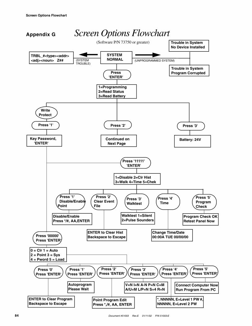
Screen Options Flowchart
84 Document #51003 Rev.E 01/11/02 P/N 51003:E
Appendix G Screen Options Flowchart(Software P/N 73750 or greater) Trouble in System
No Device Installed
Trouble in SystemProgram Corrupted
SYSTEMNORMAL
TRBL_#<type><addr><adj><noun> Z## (UNPROGRAMMED SYSTEM)(SYSTEM
TROUBLE)
Press 'ENTER'
1=Programming2=Read Status3=Read Battery
Press '2' Press '3' Press '1'
WriteProtect
Key Password, 'ENTER'
Continued on Next Page
Battery: 24V
Press '11111' 'ENTER'
1=Disable 2=Clr Hist3=Walk 4=Time 5=Chek
Press '1' Disable/Enable Point
Press '2'Clear Event File
Press '3' Walktest
Press '4' Time
Press '5' Program Check
Disable/EnablePress */#, AA,ENTER
ENTER to Clear Hist Backspace to Escape
Walktest 1=Silent 2=Pulse Sounders
Press '00000'Press 'ENTER'
Change Time/Date 00:00A TUE 00/00/00
Program Check OKRetest Panel Now
0 = Clr 1 = Auto2 = Point 3 = Sys4 = Pword 5 = Load
Press '0'Press 'ENTER'
Press '1'Press 'ENTER'
Press '2'Press 'ENTER'
Press '3' Press 'ENTER'
ENTER to Clear Program Backspace to Escape
Press '4' Press 'ENTER'
Press '5' Press 'ENTER'
AutoprogramPlease Wait
Point Program EditPress *,/#, AA, ENTER
V=N I=N A-N P=N C=M A/U=M L/P=N S=4 R=N
*, NNNNN, E=Level 1 PW #, NNNNN, E=Level 2 PW
Connect Computer NowRun Program From PC
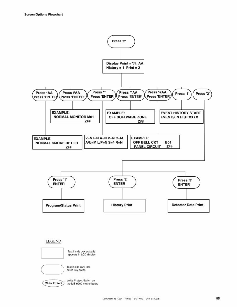
Document #51003 Rev.E 01/11/02 P/N 51003:E 85
Screen Options Flowchart
Press '2'
Display Point = */#, AAHistory = 1 Print = 2
Press *AAPress 'ENTER'
Press #AAPress 'ENTER'
Press **Press 'ENTER'
Press **AA Press 'ENTER'
EXAMPLE: NORMAL SMOKE DET I01 Z##
Press *#AA Press 'ENTER'
Press '1' Press '2'
EXAMPLE: NORMAL MONITOR M01 Z##
V=N I=N A=N P=N C=MA/U=M L/P=N S=4 R=N
EXAMPLE: OFF SOFTWARE ZONE Z##
EXAMPLE: OFF BELL CKT B01 PANEL CIRCUIT Z##
EVENT HISTORY STARTEVENTS IN HIST:XXXX
Press '2'ENTER
Detector Data Print
Press '3'ENTER
History Print
LEGEND
Text inside box actually appears in LCD display
Text inside oval indi-cates key press
Write Protect Switch on the MS-9200 motherboardWrite Protect
Program/Status Print
Press '1'ENTER

86 Document #51003 Rev.E 01/11/02 P/N 51003:E
Notes
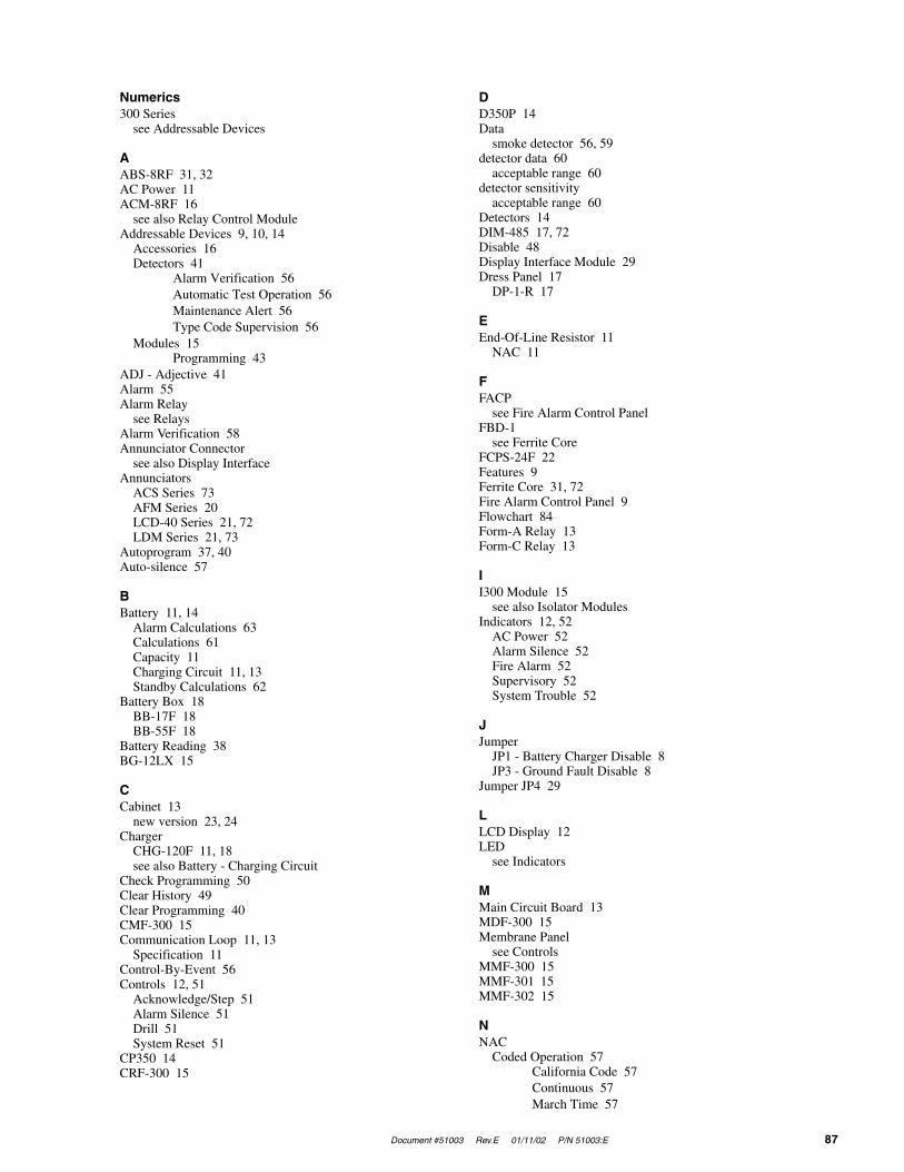
Document #51003 Rev.E 01/11/02 P/N 51003:E 87
Numerics300 Series
see Addressable Devices
AABS-8RF 31, 32AC Power 11ACM-8RF 16
see also Relay Control ModuleAddressable Devices 9, 10, 14
Accessories 16Detectors 41
Alarm Verification 56Automatic Test Operation 56Maintenance Alert 56Type Code Supervision 56
Modules 15Programming 43
ADJ - Adjective 41Alarm 55Alarm Relay
see RelaysAlarm Verification 58Annunciator Connector
see also Display InterfaceAnnunciators
ACS Series 73AFM Series 20LCD-40 Series 21, 72LDM Series 21, 73
Autoprogram 37, 40Auto-silence 57
BBattery 11, 14
Alarm Calculations 63Calculations 61Capacity 11Charging Circuit 11, 13Standby Calculations 62
Battery Box 18BB-17F 18BB-55F 18
Battery Reading 38BG-12LX 15
CCabinet 13
new version 23, 24Charger
CHG-120F 11, 18see also Battery - Charging Circuit
Check Programming 50Clear History 49Clear Programming 40CMF-300 15Communication Loop 11, 13
Specification 11Control-By-Event 56Controls 12, 51
Acknowledge/Step 51Alarm Silence 51Drill 51System Reset 51
CP350 14CRF-300 15
DD350P 14Data
smoke detector 56, 59detector data 60
acceptable range 60detector sensitivity
acceptable range 60Detectors 14DIM-485 17, 72Disable 48Display Interface Module 29Dress Panel 17
DP-1-R 17
EEnd-Of-Line Resistor 11
NAC 11
FFACP
see Fire Alarm Control PanelFBD-1
see Ferrite CoreFCPS-24F 22Features 9Ferrite Core 31, 72Fire Alarm Control Panel 9Flowchart 84Form-A Relay 13Form-C Relay 13
II300 Module 15
see also Isolator ModulesIndicators 12, 52
AC Power 52Alarm Silence 52Fire Alarm 52Supervisory 52System Trouble 52
JJumper
JP1 - Battery Charger Disable 8JP3 - Ground Fault Disable 8
Jumper JP4 29
LLCD Display 12LED
see Indicators
MMain Circuit Board 13MDF-300 15Membrane Panel
see ControlsMMF-300 15MMF-301 15MMF-302 15
NNAC
Coded Operation 57California Code 57Continuous 57March Time 57
88 Document #51003 Rev.E 01/11/02 P/N 51003:E
Temporal Code 57see also Notification Appliance Circuits 26
NFPA Standard 77Normal 52Notification Appliance Circuits 11, 13, 26, 56
Specification 11Style Y 26Style Z 26
Noun 42
OOutput Circuits 13
PPassword 39
Change 46Piezo
see SounderPIM-24
Installation 35, 36PC Configuration 35Printer Configuration 35
PK-9200W 17see also Programming Utility
Point Edit 44Power 25
Nonresettable 11, 13, 25Primary 25
see also AC Power 25Remote Field Charger Power Supply 22
see also FCPS-24FResettable 13, 25Smoke Detector 11Special Purpose 12, 25
Presignal 57Printer Connection
see also Printer/PC InterfacePrinter/PC Interface Module 29, 36Product Description 9Programming 37, 39
Level One 38, 39, 40Level Two 38, 39, 47
RRA400Z 14Read Status 58
Display Point 59History 60Print Detector Data 60Print History 60Print Program 60
Recall/Increment 42Relay Control Module 32Relay Transmitter Module 29
Components 34Relays 11, 13, 26, 32RTM-8F 16, 27, 31, 80, 81
Installation 33Power-Limited 27see also Relay/Transmitter Module
SSD350 14SD350T 14Signaling Line Circuit
see also SLC 28Silence Inhibit 57SLC 28
see also Communication LoopStyle 6 58
smoke detectorchamber reading 60data 56, 59data, printout 60printout 60sensitivity 60testing 60
SoftwareCorrelation 66Zones 65
Sounder 12Specifications 11Supervisory 55Supervisory Relay
see RelaysSystem Edit 45
Ttesting
smoke detector 60Time and Date 50Transformer Assembly 14Trouble 53
Detector 53Module 54
Trouble Relaysee Relays
Trouble Reminder 57Type Code 43, 44
UUDACT-F 17
MountingExternal 31Internal 30
see also Universal Digital Alarm Communicator/Transmitter
UL Power-limited Wiring 27Universal Digital Alarm Communicator/Transmitter 29
WWalktest 49Wire Requirements 83
XXRM-24
see Transformer

Document #51003 Rev.E 01/11/02 P/N 51003:E 89
Notes

90 Document #51003 Rev.E 01/11/02 P/N 51003:E
Notes

LimWarLg.p65 01/10/2000
The manufacturer warrants its products to be free from defects in materials and workmanshipfor eighteen (18) months from the date of manufacture, under normal use and service. Productsare date-stamped at time of manufacture. The sole and exclusive obligation of the manufactureris to repair or replace, at its option, free of charge for parts and labor, any part which isdefective in materials or workmanship under normal use and service. For products not underthe manufacturer's date-stamp control, the warranty is eighteen (18) months from date oforiginal purchase by the manufacturer's distributor unless the installation instructions or catalogsets forth a shorter period, in which case the shorter period shall apply. This warranty is voidif the product is altered, repaired, or serviced by anyone other than the manufacturer or itsauthorized distributors, or if there is a failure to maintain the products and systems in whichthey operate in a proper and workable manner. In case of defect, secure a Return MaterialAuthorization form from our customer service department. Return product, transportationprepaid, to the manufacturer.
This writing constitutes the only warranty made by this manufacturer with respect to itsproducts. The manufacturer does not represent that its products will prevent any loss by fireor otherwise, or that its products will in all cases provide the protection for which they areinstalled or intended. Buyer acknowledges that the manufacturer is not an insurer and assumesno risk for loss or damages or the cost of any inconvenience, transportation, damage, misuse,abuse, accident, or similar incident.
THE MANUFACTURER GIVES NO WARRANTY, EXPRESSED OR IMPLIED, OFMERCHANTABILITY, FITNESS FOR ANY PARTICULAR PURPOSE, OR OTHERWISEWHICH EXTEND BEYOND THE DESCRIPTION ON THE FACE HEREOF. UNDERNO CIRCUMSTANCES SHALL THE MANUFACTURER BE LIABLE FOR ANY LOSSOF OR DAMAGE TO PROPERTY, DIRECT, INCIDENTAL, OR CONSEQUENTIAL,ARISING OUT OF THE USE OF, OR INABILITY TO USE THE MANUFACTURER'SPRODUCTS. FURTHERMORE, THE MANUFACTURER SHALL NOT BE LIABLE FORANY PERSONAL INJURY OR DEATH WHICH MAY ARISE IN THE COURSE OF, ORAS A RESULT OF, PERSONAL, COMMERCIAL, OR INDUSTRIAL USE OF ITSPRODUCTS.
This warranty replaces all previous warranties and is the only warranty made by themanufacturer. No increase or alteration, written or verbal, of the obligation of this warrantyis authorized.
Limited Warranty

World HeadquartersOne Fire-Lite Place, Northford, CT 06472-1653 USA
203-484-7161 • Fax 203-484-7118www.firelite.com