Embed Size (px)
DESCRIPTION
good
Citation preview
Vol- 11, Issue- I, February- 2014 ISSN 2321 � 0397 (Online)
1 SANSHODHAN KRANTI
International Multidisciplinary Research Journal
Visit: www.emrj.net
MICROTURBINE
Mr.Jadhav Sandip Sitaram
M.E.IInd Year,Heat Power Engineering,
D.P.E.S.College,Wagholi,Pune University,India.
ABSTRACT:
A new small gas turbine technology is being developed which promises to bring the
economic, environmental and convenience benefits, advancements in the automotive sector,
generation of electricity and mechanical power needs of the commercial sector. The technology
is of the micro turbines. The micro turbine is an example of Micro Electro Mechanical Systems,
which is efficiently used to develop power at a small scale. Micro turbines are small combustion
turbines approximately the size of a refrigerator with outputs of 25 kW to 500 kW. Micro
turbines are part of the future of onsite, or distributed energy and power generation. They are
actually single shaft machines, in which turbine, compressor and generator are mounted on the
single shaft.
This unit can be used for distributed power, stand-alone power, stand-by power and vehicle application like turbocharger. The commercial customer requirement for small prime movers are that they be very cleans (low NOx, CO and unburned hydrocarbons), of better efficiency than the reciprocating engines, require infrequent maintenance, have a very low forced outage rate and of course be of low installed cost so as to provide rapid payback for the owner. These conditions are better fulfilled by the micro turbines compared to the conventional Reciprocating Engines, Gas turbines, Coal fired steam engines etc KEYWORDS:MEMS:Micro-Electro-Mechanical Systems (MEMS), DG Distribution generation
1. INTRODUCTION:
TURBINES:�Turbo Machine� is defined as a device that extracts energy from a continuously
flowing fluid by the dynamic action of one or more rotating elements .The prefix �turbo� is a
Latin word meaning �spin� or �whirl� implying that turbo machines rotate in some way.
Types of Turbines:
1.Steam Turbines
2.GasTurbines (Combustion Turbines) 3.Water (Hydraulic) Turbines
Steam Turbines:A steam turbine is mainly used as an ideal prime mover in which heat energy
transformed into mechanical energy in the form of rotary motion. In steam turbines, the heat
energy of the steam is first converted into kinetic (velocity) energy which in turn is transformed
into mechanical energy of rotation and then drives the generator for the power generation.

Vol- 11, Issue- I, February- 2014 ISSN 2321 � 0397 (Online)
2 SANSHODHAN KRANTI
International Multidisciplinary Research Journal
Visit: www.emrj.net
Classification of Steam Turbines
Based on action of steam or type of expansion:
1. Impulse or velocity or De Laval turbine
2. Reaction or pressure or Parson�s turbine
3. Combination turbine
Based on number of stages:
1. Single stage turbine 2. Multi-stage turbine
Based on type of steam flow:1.Axial flow turbine 2. Radial flow turbine
Impulse Turbines (De Laval Turbine): In this type of turbine, steam is initially expanded in a
nozzle from high pressure to low pressure. High velocity jet of steam coming out of the nozzle is
made to glide over a curved vane, called �Blade�.
Gas turbines:A Gas turbine uses the hot gases of combustion directly to produce the mechanical
power.Fuels used - Kerosene, coal, coal gas, bunker oil, gasoline, producer gas, etc.
Classification:
1.Open cycle gas turbine:The entire flow of the working substance comes from atmosphere
and is returned to the atmosphere back in each cycle.
2.Closed cycle gas turbine:The flow of the working substance of specified mass is
confined within the cyclic path. ( Air or Helium is the working substance)
Water (hydraulic) turbines:It is a prime mover, which converts hydro power (energy of water)
into mechanical energy and further into hydro-electric power
Classification of Water Turbines
Based on action of water:
1. Impulse turbine � pelton wheel.
2. Reaction turbine � francis and kaplan.
Based on name of originator:
1. Pelton turbine or Pelton wheel 2.Francis turbine
3.Kaplan turbine
Based on head of water:
1. Low head turbine 2.Medium head turbine
3.High head turbine
1.1MEMS:Micro-Electro-Mechanical Systems (MEMS) is an integration of mechanical
elements, sensors, actuators, and electronics on a common silicon substrate through the
Vol- 11, Issue- I, February- 2014 ISSN 2321 � 0397 (Online)
3 SANSHODHAN KRANTI
International Multidisciplinary Research Journal
Visit: www.emrj.net
utilization of micro fabrication technology. MEM is truly an enabling technology allowing the
development of smart products by augmenting the computational ability of microelectronics with
the perception and control capabilities of micro sensors and micro actuators. MEMS technology
makes possible the integration of microelectronics with active perception and control functions,
thereby, greatly expanding the design and application space.
Although MEMS devices are extremely small (e.g. MEMS has enabled electrically-
driven motors smaller than the diameter of a human hair to be realized), MEMS technology is
not about size. Furthermore, MEMS is not about making things out of silicon, even though
silicon possesses excellent materials properties making it a attractive choice for many high-
performance mechanical applications. Instead, MEMS is a manufacturing technology; a new way
of making complex electromechanical systems (like power generation) using batch fabrication
techniques. Already, MEMS is used for everything ranging from in-dwelling blood pressure
monitoring to active suspension systems for automobiles.
Recent examples of the advantages of MEMS technology consider the MEMS
accelerometers, which are quickly replacing conventional accelerometers for crash air-bag
deployment systems in automobiles. Microturbine is one of the best examples of the recently
used MEMS. The technology is to generate power for at a small level for a few houses or as a
stand-by power source. It is given hype now days and further research work is also in progress.
Now let us know what exactly the microturbine is.
1.2 Gas Turbine:
Gas turbines are Braxton cycle engines, which extract energy from hydrocarbon fuels
through compression, combustion, and hot gas expansion. Air is drawn in to a compressor, which
increases the air pressure. The compressed air is mixed with fuel and ignited in a combustor.
Then, the hot gas is expanded through a turbine, which drives the compressor and gives useful
work through rotation of the compressor- turbine shaft. The shaft power can be used to drive a
electrical generator, thereby providing electricity.
1.3 Micro turbine:
Micro turbines are small gas turbines used to generate electricity. Occupying a space no larger
than a telephone box, they typically have power outputs in the range of 25 to 300kW. In
comparison, large power stations are entire buildings and have much higher power outputs of
around 600 MW to 1000MW. The small size of micro turbines is a major advantage that allows
them to be situated right at the source of electricity demand. This eliminates energy losses that
Vol- 11, Issue- I, February- 2014 ISSN 2321 � 0397 (Online)
4 SANSHODHAN KRANTI
International Multidisciplinary Research Journal
Visit: www.emrj.net
usually occur when transmitting electricity from power stations. Such transmission losses are
quite significant and can easily amount to 7% of the power generated.Micro turbines are a new
class of small gas turbines used for distributed generation of electricity. Micro turbines are small
version of gas turbines emerged from four different technologies viz. small gas turbines,
auxiliary power units, automotive development gas turbine and turbochargers. Micro turbines are
new class of gas turbines used for distributed generation of electricity. Micro turbine
development is based on turbines used for aircraft auxiliary power units, which have been used
in commercial airlines for decades.One way in which micro turbines can be distinguished from
larger turbines is that micro turbines use a single shaft to drive the compressor, turbine and
generator. Where as in large power plants, the turbines and generator are on separate shafts and
are connected by gears that slow down the high-speed rotation of the gas turbines,
simultaneously increasing the torque sufficient to turn much large electric generators. Some
micro turbines even include the ability to generate electricity from heat of exhaust gases.
2.0 HISTORY:
In 1900 when a 2 MW steam turbine was installed at Hartford, its size was 4 times bigger than
any of the existing steam turbines. From then on economy of scale meant bigger and bigger. By
the end of the 1970s and largely driven by nuclear power plants, steam turbines exceeded 1000
MW. The electric efficiency of steam turbine power plants eventually reached 34%. That trend
was broken in the 1980s. More efficient gas turbines combined with steam turbines could
produce electric power with efficiencies up to 55%. This new technology, combined cycle power
plants, was the technology of choice for independent power producers. It was now possible to
build competitive power plants down to the range of 100-200 MW. Micro turbines have been
experimented with since 1945, when Rover tried to develop one for a vehicle application. Since
that time, automobile, aerospace, aircraft and military contractors have tried to develop an
economical and functional microturbine for different industrial and commercial applications.
3.0 NEED OF MICROTURBINE:
In today's energy economy, most electricity is produced using fossil fuel-burning
generators. These machines consist of a motor and a dense coil of copper wires that surround a
shaft containing powerful magnets. To get that power to a home or factory typically requires a
local utility to run a heavy copper cable to the residence or business site.
But what if the site requiring energy is in a remote mountain location, or it's an offshore
oil rig where electricity is scarce and hookups don't exist? Here the microturbines come into the

Vol- 11, Issue- I, February- 2014 ISSN 2321 � 0397 (Online)
5 SANSHODHAN KRANTI
International Multidisciplinary Research Journal
Visit: www.emrj.net
picture. It is one of the best options to set up a local power-generation plant, perhaps using a
micro turbine -- a small, sometimes portable, fossil fuel-burning system that can provide enough
electricity to power anywhere from 10 to 5,000 homes.Also it has an important application as a
turbocharger in vehicles when more energy is required from the engine in less amount of fuel.
4.CONSTRUCTION OMICROTURBINE:
Micro turbines are typically single shaft machines with the compressor and turbine
mounted on the same shaft as the electrical generator. It therefore consists of only one rotating
part, eliminating the need for a gearbox and associated numerous moving parts. Micro turbines
are miniature versions of the huge machines used to generate power from natural gas, and
evolved from aircraft engines and automotive turbochargers.
A cutaway view of a micro turbine is shown in Figure1. The single stage Turbine and
Compressor wheels are inertia welded to the shaft, which supports the generator alternator rotor
and provides for a cold end drive. A block diagram showing a complete cycle of the micro
turbine is shown in Figure2. The inner bearing is a hydrodynamic bearing and the outer bearing
utilizes a ceramic ball race. A device called recuperator plays an important role in completing the
cycle of micro turbine.
Fig 1: Sectional view of a typical micro turbine .
4. PRINCIPLE AND WORKING OF MICROTURBINES:
The high velocity exhaust gases coming from the combustor rotate the turbine used in the
microturbine. The basic principle of working of the microturbine is that the compressor as well
as the electric generator is mounted on the same power shaft as that of the turbine. Because of
this the compressor and the generator also rotate with the turbine.
The generator rotates with the same speed as that of the turbine and generates the
electricity. The electricity is first given to the power conditioning devices and then it is supplied
Vol- 11, Issue- I, February- 2014 ISSN 2321 � 0397 (Online)
6 SANSHODHAN KRANTI
International Multidisciplinary Research Journal
Visit: www.emrj.net
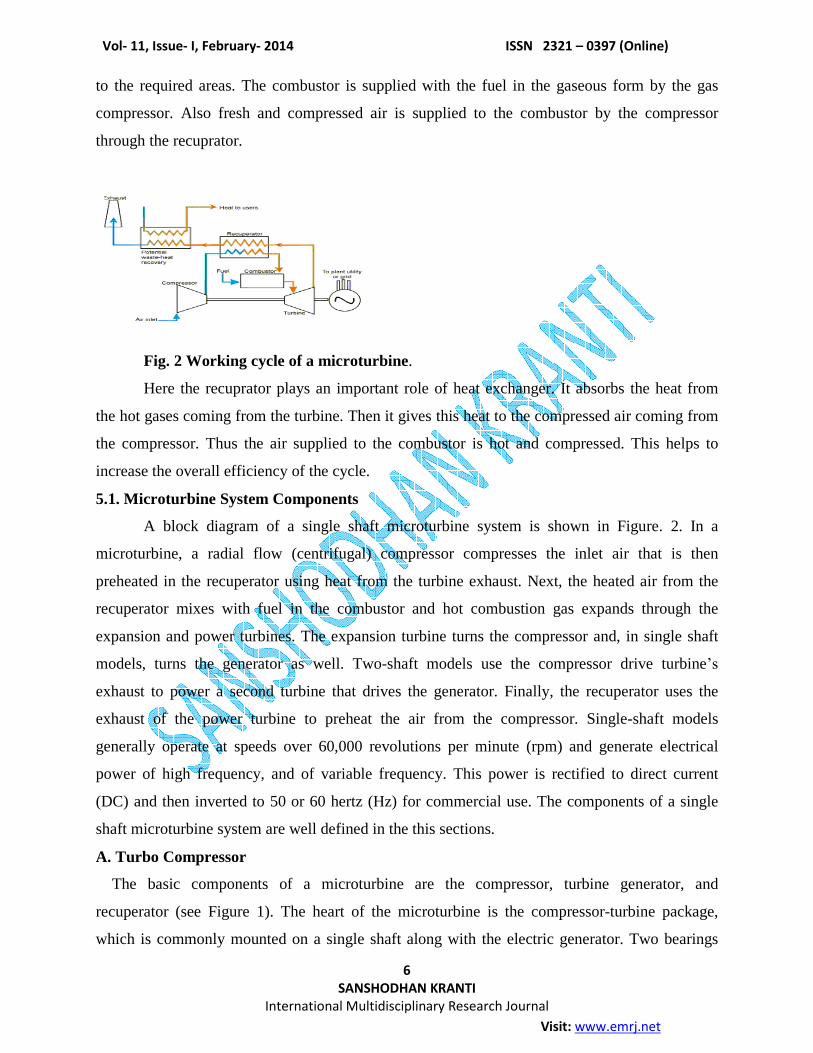
to the required areas. The combustor is supplied with the fuel in the gaseous form by the gas
compressor. Also fresh and compressed air is supplied to the combustor by the compressor
through the recuprator.
Fig. 2 Working cycle of a microturbine.
Here the recuprator plays an important role of heat exchanger. It absorbs the heat from
the hot gases coming from the turbine. Then it gives this heat to the compressed air coming from
the compressor. Thus the air supplied to the combustor is hot and compressed. This helps to
increase the overall efficiency of the cycle.
5.1. Microturbine System Components
A block diagram of a single shaft microturbine system is shown in Figure. 2. In a
microturbine, a radial flow (centrifugal) compressor compresses the inlet air that is then
preheated in the recuperator using heat from the turbine exhaust. Next, the heated air from the
recuperator mixes with fuel in the combustor and hot combustion gas expands through the
expansion and power turbines. The expansion turbine turns the compressor and, in single shaft
models, turns the generator as well. Two-shaft models use the compressor drive turbine�s
exhaust to power a second turbine that drives the generator. Finally, the recuperator uses the
exhaust of the power turbine to preheat the air from the compressor. Single-shaft models
generally operate at speeds over 60,000 revolutions per minute (rpm) and generate electrical
power of high frequency, and of variable frequency. This power is rectified to direct current
(DC) and then inverted to 50 or 60 hertz (Hz) for commercial use. The components of a single
shaft microturbine system are well defined in the this sections.
A. Turbo Compressor
The basic components of a microturbine are the compressor, turbine generator, and
recuperator (see Figure 1). The heart of the microturbine is the compressor-turbine package,
which is commonly mounted on a single shaft along with the electric generator. Two bearings

Vol- 11, Issue- I, February- 2014 ISSN 2321 � 0397 (Online)
7 SANSHODHAN KRANTI
International Multidisciplinary Research Journal
Visit: www.emrj.net
support the single shaft. The single moving part of the one-shaft design has the potential for
reducing maintenance needs and enhancing overall reliability. In microturbines, the
turbocompressor shaft generally turns at high rotational speed, about 96,000 rpm in the case of a
30 kW machine and about 80,000 rpm in a 75 kW machine. One 45 kW model on the market
turns at 116,000 rpm There is no single rotational speedpower size rule, as the specific turbine
and compressor design characteristics strongly influence the physical size of components and
consequently rotational speed. For a specific aerodynamic design, as the power rating decreases,
the shaft speed increases, hence the high shaft speed of the small microturbines. Recuperators are
heat exchangers that use the hot turbine exhaust gas (typically around 1,200ºF) to preheat the
compressed air (typically around 300ºF) going into the combustor, thereby reducing the fuel
needed to heat the compressed air to turbine inlet temperature. Depending on microturbine
operating parameters, recuperators can more than double machine efficiency. The controllers of
the gas turbine implements three major control loops: start up, speed and temperature. For the
purpose of these modeling tests, the speed control, recives the most attention. The reason for this
is that during start up, the unit is not on-line, and in temperature control mode, the governor will
not respond to system frequency changes. The primary valve demand control signal is selected
by a low value select gate from the outputs of these control loops [3].
B. Generator
The microturbine produces electrical power via a highspeed generator turning on the
single turbo-compressor shaft. The high-speed generator of the single-shaft design employs a
permanent magnet (typically Samarium- Cobalt) alternator, and requires that the high frequency
AC output (about 1,600 Hz for a 30 kW machine) be converted to 50 or 60 Hz for general use.
This power conditioning involves rectifying the high frequency AC sto DC, and then inverting
the DC to 50 or 60 Hz AC. Power conversion comes with an efficiency penalty (approximately
five percent).
C. Power Conditioning Unit-As discussed, single-shaft microturbines feature digital power
controllers to convert the high frequency AC power produced by the generator into usable
electricity.The high frequency AC is rectified to DC, inverted back to 60 or 50 Hz AC, and then
filtered to reduce harmonic distortion.This is a critical component in the single-shaft
microturbine design and represents significant design challenges, specifically in matching
turbine output to the required load. To allow for transients and voltage spikes, power electronics
Vol- 11, Issue- I, February- 2014 ISSN 2321 � 0397 (Online)
8 SANSHODHAN KRANTI
International Multidisciplinary Research Journal
Visit: www.emrj.net
designs are generally able to handle seven times the nominal voltage. Most microturbine power
electronics are generating three phase electricity
6. PERFORMANCE:
The performance of the microturbines is given in the tabular form as below,
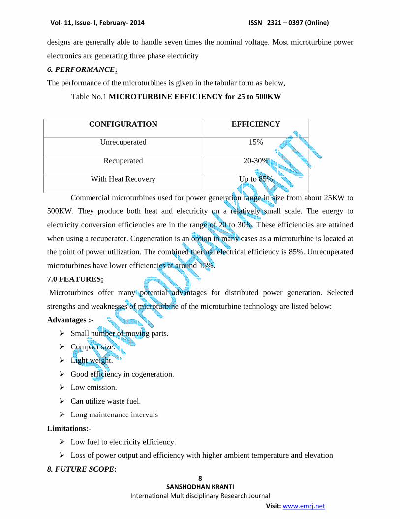
Table No.1 MICROTURBINE EFFICIENCY for 25 to 500KW
CONFIGURATION EFFICIENCY
Unrecuperated
15%
Recuperated
20-30%
With Heat Recovery Up to 85%
Commercial microturbines used for power generation range in size from about 25KW to
500KW. They produce both heat and electricity on a relatively small scale. The energy to
electricity conversion efficiencies are in the range of 20 to 30%. These efficiencies are attained
when using a recuperator. Cogeneration is an option in many cases as a microturbine is located at
the point of power utilization. The combined thermal electrical efficiency is 85%. Unrecuperated
microturbines have lower efficiencies at around 15%.
7.0 FEATURES:
Microturbines offer many potential advantages for distributed power generation. Selected
strengths and weaknesses of microturbine of the microturbine technology are listed below:
Advantages :-
Small number of moving parts.
Compact size.
Light weight.
Good efficiency in cogeneration.
Low emission.
Can utilize waste fuel.
Long maintenance intervals
Limitations:-
Low fuel to electricity efficiency.
Loss of power output and efficiency with higher ambient temperature and elevation
8. FUTURE SCOPE:

Vol- 11, Issue- I, February- 2014 ISSN 2321 � 0397 (Online)
9 SANSHODHAN KRANTI
International Multidisciplinary Research Journal
Visit: www.emrj.net
Extensive field test data collected from units currently in use at commercial and industrial
facilities will provide the manufacturers with the ability to improve the microturbine design,
lowering the cost and increasing performance, in order to produce a competitive distributed
generation product. Utilities, government agencies, and other
Organizations are involved in collaborative research and field-testing.
Development is ongoing in a variety of areas:
1. Heat recovery/co regeneration
2. Fuel flexibility
3. Vehicles
4.Hybridsystems (e.g. fuel cell/microturbine, flywheel/microturbine)
9. APPLICATIONS:
While the simplest application for a microturbine prime mover is of power generation
other application exists. Microturbine prime movers can be used for cooling, refrigeration; air
compression and pump drive application whereby the inherent high speed of the power shaft can
be used to drive high efficiency and low cost centrifugal compressors.
Microturbines can be used for stand by power, power quality and reliability, peak
shaving, and cogeneration applications. In addition, because microturbines are being developed
to utilize a variety of fuels, they are being used for resource recovery and landfill gas
applications. Microturbines produce between 25kw to 500kw of power and are well suited for
small commercial building establishments such as restaurants, hotels/motels, small offices, retail
stores and many others.
The development of the microturbine technology for the transportation application is also in
progress. One of the major applications used is the turbocharger in the small vehicles.
Automotive companies are interested in microturbines to provide a light weight and efficient
fossil fuel- based energy source for hybrid electric vehicles, especially buses.
10 CASE STUDY ON DISTRIBUTED GENERATION:
10.1 Introduction:Distribution generation is a concept of installing and operating small electric
generators, typically less than 20MW, at or near electrical load. The premise of distributed
generation is to provide electricity to a customer at a reduced cost and more efficiently with
reduced losses than the traditional utility central generating plant with transmission and
distribution wires.
10.2 Microturbine in distributed generation:
Vol- 11, Issue- I, February- 2014 ISSN 2321 � 0397 (Online)
10 SANSHODHAN KRANTI
International Multidisciplinary Research Journal
Visit: www.emrj.net
Microturbine is small scale combustion turbines ranging inside from 28 kW to 500kW, which
include a compressor, composter, turbine, alternator, recuperator and generator. Microturbines
are smaller, lighter and operate with no vibration and less noise. All of these features help to
make on - site installation possible without compromising the environmental aspects. They have
potential to be located on site having space limitations to produce power.
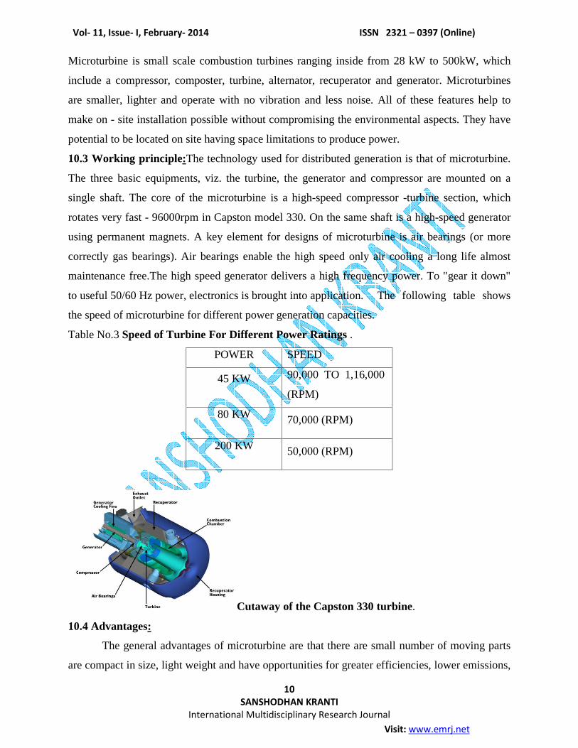
10.3 Working principle:The technology used for distributed generation is that of microturbine.
The three basic equipments, viz. the turbine, the generator and compressor are mounted on a
single shaft. The core of the microturbine is a high-speed compressor -turbine section, which
rotates very fast - 96000rpm in Capston model 330. On the same shaft is a high-speed generator
using permanent magnets. A key element for designs of microturbine is air bearings (or more
correctly gas bearings). Air bearings enable the high speed only air cooling a long life almost
maintenance free.The high speed generator delivers a high frequency power. To "gear it down"
to useful 50/60 Hz power, electronics is brought into application. The following table shows
the speed of microturbine for different power generation capacities.
Table No.3 Speed of Turbine For Different Power Ratings .
POWER SPEED
45 KW 90,000 TO 1,16,000
(RPM)
80 KW 70,000 (RPM)
200 KW 50,000 (RPM)
Cutaway of the Capston 330 turbine.
10.4 Advantages:
The general advantages of microturbine are that there are small number of moving parts
are compact in size, light weight and have opportunities for greater efficiencies, lower emissions,

Vol- 11, Issue- I, February- 2014 ISSN 2321 � 0397 (Online)
11 SANSHODHAN KRANTI
International Multidisciplinary Research Journal
Visit: www.emrj.net
lower electricity costs and use renewable fuels such as land fill or sewage treatment gases.
Microturbine in general offer to be advantages
1 lower emission and 2 low maintenance.
As illustrated below (Table no.3), the Capston microturbine has one of the best emission
performances of any fossil fuel combustion.
Table no.4 COMPARISION OF EMISSIONS
Item NO (ppm) CO (ppm) THC (ppm)
Reciprocating
Engines
(500kW)
100 340 150
Gas Turbines
(4.5MW)
25 50 10
Coal Fired
Steam
(500MW)
200 N/A N/A
Microturbine 9 25 9
Source: Cambridge Energy Research Associates.
With very low emissions and maintenance, microturbines hold promise to enable small-scale
cogeneration. To exhaust heat can be use water heating, absorption cooling, dehumidification,
etc.
It is possible to reach efficiencies of 70-80%. Because of the three exhausts with no risk
of any oil fuel (due to the air bearing) it should be possible to use the exhaust gas directly in
some industrial processes.
10.5 Benefits of Distributed generation:
Thus the benefits that distributed generation could potentially provide, depending on the
technology, include reduced emissions, utilization of waste heat, improved power quality and
reliability and deferral of transmission or distribution upgrades.
10.6 HYDROPOWER GENERATION:
A typical use of microturbine is the hydropower generation. Microturbine technology
equipments harness the best possible energy source that is the discharge flow of even minor
Vol- 11, Issue- I, February- 2014 ISSN 2321 � 0397 (Online)
12 SANSHODHAN KRANTI
International Multidisciplinary Research Journal
Visit: www.emrj.net
streams, in that sense; they constitute cleaner, superior environmental alternatives to the less
acceptable fossil fuel powered generators.
The technology is very simple as shown in figure .A turbine with a generator on its shaft
is fitted in the way of water flowing in a river or a stream.
In most cases, microturbine views only a small portion of a stream's flow that is channeled
through a penstock. As it is clear from the figure, we can say that reliable and renewable hydro-
energy generation (with the help of microturbines of course) does not require a reservoir or the
flooding of low-lying areas. Microturbine technology turbines may be installed low discharge
flow streams and rivers. They are efficient even in cases of low drop river fall, as microturbine
technology turbines generate electricity from as little as one meter of hydraulic head.
10.7 TURBOCHARGER:
Turbocharger is one of the applications of microturbine. It uses the principle of mounting
the compressor on same shaft as that of turbine. Here also the exhaust gases drive the turbine.
Today with precise control offered by the computers, turbochargers are making small engines
more efficient and capable of producing more power.
Microturbines are evolved from automotive and truck turbochargers, auxiliary power
units for airplanes, and small jet engines and are comprised of a compressor, combustor, turbine,
alternator, recuperator, and generator.
10.8 Turbocharging principle:
A turbocharger is a device that uses exhaust gases, rather than the engine power to run an air
pump or compressor. The air pump then forces an increased amount of air into the cylinders.
Both the diesel and gasoline engines in the market use turbochargers. Figure 3 shows a typical
schematic of air and exhausting a turbocharged engine. High velocity exhaust gases pass out of
the exhaust ports. From there they pass through a turbine driven pump. Here the exhaust gases
cause the exhaust turbine to turn very rapidly.
The exhaust turbine causes the intake compressor to run very rapidly. As the compressor
turbine runs it draws in a large amount of fresh air. The intake air is pressurized and forced into
the intake port. The increase in the pressure in the intake manifold is called as boost. Boost may
produce pressure in the intake manifold of about 6 to 10 psi or more depending on the
manufacturer.
Figure shows a chart that compares a turbocharged and a normally aspirated engine. Note
that both the torque and the horse power are increased at all rpm. For example at 5000 rpm the

Vol- 11, Issue- I, February- 2014 ISSN 2321 � 0397 (Online)
13 SANSHODHAN KRANTI
International Multidisciplinary Research Journal
Visit: www.emrj.net
normally aspirated engine produces about 80hp. at this rpm, the turbocharged engine can
produce about 140hp.
11. CONCLUSION:
As a breakthrough technology, allowing unparalleled synergy between hitherto unrelated
fields of endeavor such as biology and microelectronics, many new MEMS applications will
emerge, expanding beyond that which is currently identified or known. In the industrial sector,
MEMS devices are emerging as product performance differentiators in numerous markets with a
projected market growth of over 50% per year.
REFRENCES
1.Jan Peirs, Dominiek Reynaerts, Filip Verplaetsen, Michael Poesen, Pieterjan Renier, A
Microturbine for Electric Power Generation Sinaia , RomaniaSAE Paper 2002 , October 6-8,
2002
2.R. H. Staunton B. Ozpineci, Microturbine Power Conversion Technology Review, ORNL/TM-
2003/74
3. E.Schwaller, Turbocharger, Automotive Technology, Delmar publications.
4. S. E. Abdollahi and A. Vahedi, Dynamic Modeling of Micro-Turbine Generation Systems
Using Matlab/Simulink, Department of Electrical Engineering Iran University of Science and
Technology Narmak, Tehran (Iran)
5.21211 Nordhoff Street � Chatsworth � CA � 91311 � 877.716.2929 � 818 407.3770 � ⓒ2008
Capstone Turbine Corporation. 10/08 Capstone P/N 331032B
6.Environmental TechnologyVerification Report Combined Heat and Power at a Commercial
Supermarket - Capstone 60 kW Microturbine CHP System Under a Cooperative Agreement
With U.S. Environmental Protection Agency and Under Agreement With New York State
Energy Research and Development Authority SRI/USEPA-GHG-VR-27 September 2003