Embed Size (px)
Citation preview
MPLS L2VPN (VLL) Technology White Paper
Issue 1.0
Date 2012-10-30
HUAWEI TECHNOLOGIES CO., LTD.
Issue 1.0 (2012-10-30) Huawei Proprietary and Confidential
Copyright © Huawei Technologies Co., Ltd.
i
Copyright © Huawei Technologies Co., Ltd. 2012. All rights reserved.
No part of this document may be reproduced or transmitted in any form or by any means without prior
written consent of Huawei Technologies Co., Ltd.
Trademarks and Permissions
and other Huawei trademarks are trademarks of Huawei Technologies Co., Ltd.
All other trademarks and trade names mentioned in this document are the property of their respective
holders.
Notice
The purchased products, services and features are stipulated by the contract made between Huawei and
the customer. All or part of the products, services and features described in this document may not be
within the purchase scope or the usage scope. Unless otherwise specified in the contract, all statements,
information, and recommendations in this document are provided "AS IS" without warranties, guarantees or
representations of any kind, either express or implied.
The information in this document is subject to change without notice. Every effort has been made in the
preparation of this document to ensure accuracy of the contents, but all statements, information, and
recommendations in this document do not constitute a warranty of any kind, express or implied.
Huawei Technologies Co., Ltd.
Address: Huawei Industrial Base
Bantian, Longgang
Shenzhen 518129
People's Republic of China
Website: http://enterprise.huawei.com
MPLS L2VPN (VLL) Technology White Paper About This Document
Issue 1.0 (2012-10-30) Huawei Proprietary and Confidential
Copyright © Huawei Technologies Co., Ltd.
ii
About This Document
Keywords:
MPLS VLL
Abstract:
Multi-Protocol Label Switching (MPLS) technologies make it easy to provide VPN services
based on IP technologies. MPLS VPNs are highly scalable and easy-to-manage. There are two
MPLS-based VPN services: L3 MPLS VPN and L2 MPLS VPN. MPLS L2VPN has two
modes: Virtual Private LAN Service (VPLS) and Virtual Leased Line (VLL). VLL applies to
point-to-point networking scenarios, while VPLS supports point-to-multipoint and
multipoint-to-multipoint networking. From users’ point of view, the whole MPLS network is
a Layer 2 switched network, through which Layer 2 connections can be established between
sites. This document describes VLL.
Acronyms:
Acronym Full spelling
MPLS Multi-Protocol Label Switching
VLL Virtual Leased Line
MPLS L2VPN (VLL) Technology White Paper Contents
Issue 1.0 (2012-10-30) Huawei Proprietary and Confidential
Copyright © Huawei Technologies Co., Ltd.
iii
Contents
About This Document .................................................................................................................... ii
1 Overview ......................................................................................................................................... 1
2 Basic Model .................................................................................................................................... 3
2.1 MPLS L2VPN Model....................................................................................................................................... 3
2.2 Advantages of the MPLS L2VPN .................................................................................................................... 4
3 Features ........................................................................................................................................... 5
3.1 Terminologies ................................................................................................................................................... 5
3.2 Frame Format ................................................................................................................................................... 5
3.3 Packet Forwarding Process .............................................................................................................................. 6
4 Implementation of the MPLS L2VPN (VLL) ........................................................................... 7
4.1 CCC Mode ....................................................................................................................................................... 7
4.2 Martini Mode ................................................................................................................................................... 8
4.3 Kompella Mode .............................................................................................................................................. 10
5 VLL Application .......................................................................................................................... 11
MPLS L2VPN (VLL) Technology White Paper 1 Overview
Issue 1.0 (2012-10-30) Huawei Proprietary and Confidential
Copyright © Huawei Technologies Co., Ltd.
1
1 Overview
As the world economy develops, increasing enterprises have to span greater distances to
provide quality services to an extensive clientele base. The employees of these enterprises
also have to travel more frequently. As a result, enterprises seek out services that enable them
to interconnect their branches, so that their employees can easily access enterprise networks
from anywhere.
Originally, service providers filled this need by providing leased lines, but leased lines have
significant disadvantages. For example, leased lines are not applicable when there are a large
number of branches or when the number of branches grows quickly. Furthermore, this method
is expensive and a network based on leased lines is difficult to manage.
Then, Asynchronous Transfer Mode (ATM) and Frame Relay (FR) emerged, and service
providers turned to them to provide virtual circuits. With these new methods, enterprises
could establish their own Layer 3 networks for IP or IPX traffic based on the virtual circuits.
However, the virtual links are point-to-point Layer 2 links, which make networks difficult to
configure and maintain, especially when a new site is deployed.
Later, after IP networks had become present almost everywhere in the world, service
providers began to focus on how to provide enterprises with low-cost private network services
using the existing IP networks.
The Multi-protocol Label Switching (MPLS) VPN technology, which is easy to configure and
allows service providers to change bandwidth settings easily, address this demand. This
technology uses a short but fixed-length label to encapsulate network layer packets, and
integrates IP's connectionless control and ATM's connection-oriented packet forwarding.
Apart from IP routing and control protocols, MPLS also supports policy-based routing,
meeting requirements of emerging applications. MPLS was initially developed to improve
forwarding speeds of routers. Due to its intrinsic advantages, it is not limited to this
application. For example, MPLS has been widely applied to traffic engineering, VPN services,
and other areas. As a result, it has gradually become an important standard for large-scale IP
networks.
Traditional VPN technologies use L2 tunneling protocols (such as L2TP, L2F and PPTP) or
the L3 tunneling technologies (IPSec and GRE). These technologies were quite successful and
widely applied. However, as the use of VPNs expanded, their drawbacks, such as its
expansion and management limitations, have become more obvious. In addition, quality of
service (QoS) and security are tough problems for the traditional VPN technologies.
The MPLS technology can easily implement IP-based VPN services and satisfy the
requirements for VPN expandability and manageability. MPLS VPNs allow for
implementation of value-added services. A single access point can be configured with
MPLS L2VPN (VLL) Technology White Paper 1 Overview
Issue 1.0 (2012-10-30) Huawei Proprietary and Confidential
Copyright © Huawei Technologies Co., Ltd.
2
multiple VPNs, each representing a different service, so that the network can transmit
different services
There are two types of MPLS-based VPN services: MPLS L3VPN and MPLS L2VPN. The
L2 MPLS VPN service comprises VPLS and VLL, where VLL applies to point-to-point
networking and VPLS applies to point-to-point and multipoint-to-multipoint VPN scenarios.
From the user’s point of view, the entire MPLS network is an L2 switching network through
which L2 connections can be set up between different sites.
This document focuses on the L2 MPLS VPN in VLL mode.
MPLS L2VPN (VLL) Technology White Paper 2 Basic Model
Issue 1.0 (2012-10-30) Huawei Proprietary and Confidential
Copyright © Huawei Technologies Co., Ltd.
3
2 Basic Model
2.1 MPLS L2VPN Model
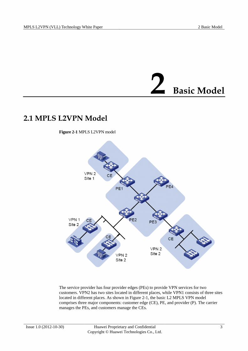
Figure 2-1 MPLS L2VPN model
The service provider has four provider edges (PEs) to provide VPN services for two
customers. VPN2 has two sites located in different places, while VPN1 consists of three sites
located in different places. As shown in Figure 2-1, the basic L2 MPLS VPN model
comprises three major components: customer edge (CE), PE, and provider (P). The carrier
manages the PEs, and customers manage the CEs.
MPLS L2VPN (VLL) Technology White Paper 2 Basic Model
Issue 1.0 (2012-10-30) Huawei Proprietary and Confidential
Copyright © Huawei Technologies Co., Ltd.
4
2.2 Advantages of the MPLS L2VPN Higher expandability
MPLS VPN is much easier to expand than the traditional ATM or FR network. MPLS
VPNs can multiplex multiple virtual circuits in the same LSP. A PE only maintains
information about one LSP for the virtual circuits; therefore, the system capacity is easy
to expand.
Clear management responsibility
The MPLS L2VPN carrier only provides L2 connectivity, whereas L3 connectivity is
provided by customers. Therefore, route flapping caused by incorrect configuration on a
user network does not affect stability of the carrier’s network.
Higher security and confidentiality
MPLS VPN can provide security and confidentiality equivalent to that of the ATM or FR
VPN network. Since users maintain their own routing information, the carrier does not
need to worry about address overlapping among the users or whether the routing
information of a user will be disclosed to private networks of other users. This alleviates
the management load of the carrier while enhancing security of user information.
Support for multiple network protocols
As the carrier only provides L2 connectivity, customers can use any L3 protocol, such as
IP, IPv6, IPX and SNA.
Smooth upgrade from traditional L2VPN
MPLS L2VPN is transparent to users. When the carrier upgrades the traditional L2VPN
networks, such as ATM and FR networks, to the MPLS L2VPN networks, the customers
do not need to make any configuration. The upgrade has almost no impact on the
customers except that data may be lost for a short time during the transition.
MPLS L2VPN (VLL) Technology White Paper 3 Features
Issue 1.0 (2012-10-30) Huawei Proprietary and Confidential
Copyright © Huawei Technologies Co., Ltd.
5
3 Features
3.1 Terminologies Virtual Leased Line (VLL): A point-to-point L2VPN service provided on the MPLS
network. Virtual Private LAN Service (VPLS): A point-to-multipoint and
multipoint-to-multipoint L2 VPN service provided on the MPLS network.
Custom Edge (CE): User edge device directly connected to the service provider. The CE
can be a router or a switch. It cannot detect VPNs by itself.
Provider Edge (PE): Carrier device directly connected to the CE. All the processing on
the VPN is conducted on the PE of the MPLS network. The PE must support MPLS
VPN.
Provider (P): Backbone device on the carrier’s MPLS network. The P is not directly
connected to the CE. The P must support MPLS.
Penultimate Hop Popping (PHP): To pop up a layer of label to simplify label search in
MPLS and IP switching.
Circuit Cross Connect (CCC): An L2 MPLS VPN implementation mode.
Label Switched Path (LSP): A data forwarding path established through signaling or
static configuration on the MPLS network.
Label Distribution Protocol (LDP): One of the core protocols of MPLS. It classifies
packets, attaches labels to different types of packets, and establishes the label switching
path.
3.2 Frame Format
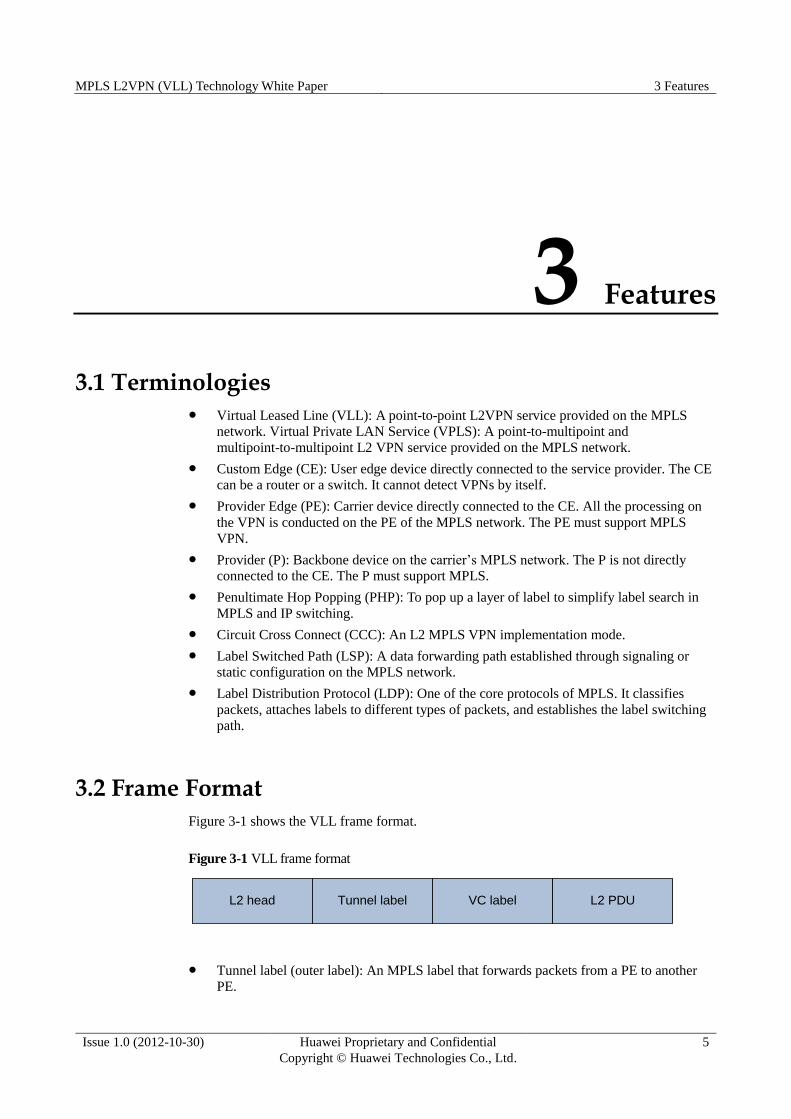
Figure 3-1 shows the VLL frame format.
Figure 3-1 VLL frame format
Tunnel label (outer label): An MPLS label that forwards packets from a PE to another
PE.
L2 head Tunnel label VC label L2 PDU
MPLS L2VPN (VLL) Technology White Paper 3 Features
Issue 1.0 (2012-10-30) Huawei Proprietary and Confidential
Copyright © Huawei Technologies Co., Ltd.
6
VC label (inner label): A label that identifies the PE-CE link. In CCC mode, the L2
MPLS VPN does not have such a label.
MPLS L2VPN supports the following link layer encapsulation modes: Ethernet and
VLAN. Nodes in the same VPN must use the same encapsulation mode.
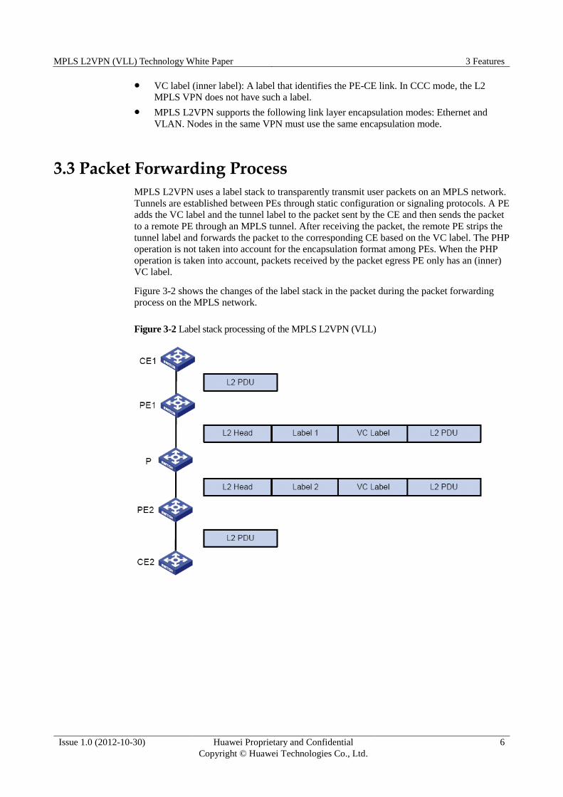
3.3 Packet Forwarding Process
MPLS L2VPN uses a label stack to transparently transmit user packets on an MPLS network.
Tunnels are established between PEs through static configuration or signaling protocols. A PE
adds the VC label and the tunnel label to the packet sent by the CE and then sends the packet
to a remote PE through an MPLS tunnel. After receiving the packet, the remote PE strips the
tunnel label and forwards the packet to the corresponding CE based on the VC label. The PHP
operation is not taken into account for the encapsulation format among PEs. When the PHP
operation is taken into account, packets received by the packet egress PE only has an (inner)
VC label.
Figure 3-2 shows the changes of the label stack in the packet during the packet forwarding
process on the MPLS network.
Figure 3-2 Label stack processing of the MPLS L2VPN (VLL)
MPLS L2VPN (VLL) Technology White Paper 4 Implementation of the MPLS L2VPN (VLL)
Issue 1.0 (2012-10-30) Huawei Proprietary and Confidential
Copyright © Huawei Technologies Co., Ltd.
7
4 Implementation of the MPLS L2VPN (VLL)
4.1 CCC Mode
Circuit Cross Connect (CCC) is the mode in which VLL is implemented through static LSPs.
Unlike common MPLS L2VPN, CCC uses one layer of label (tunnel label) to transmit user
data. Therefore, each LSP is exclusively used by a virtual circuit. A transparent connection
can be configured between a PE and CE. Packets of the source CE can be sent to the
destination CE.
CCC falls into local CCC and remote CCC. In local CCC mode, two CEs are connected to the
same PE, and the PE is equivalent to an L2 switch. In remote CCC mode, two CEs are
connected to different PEs and use the exclusive static LSP between the PEs as a tunnel. This
mode does not need any signaling protocol to transfer L2 VPN information. The PEs use the
label corresponding to the LSP to forward packets.
MPLS L2VPN (VLL) Technology White Paper 4 Implementation of the MPLS L2VPN (VLL)
Issue 1.0 (2012-10-30) Huawei Proprietary and Confidential
Copyright © Huawei Technologies Co., Ltd.
8
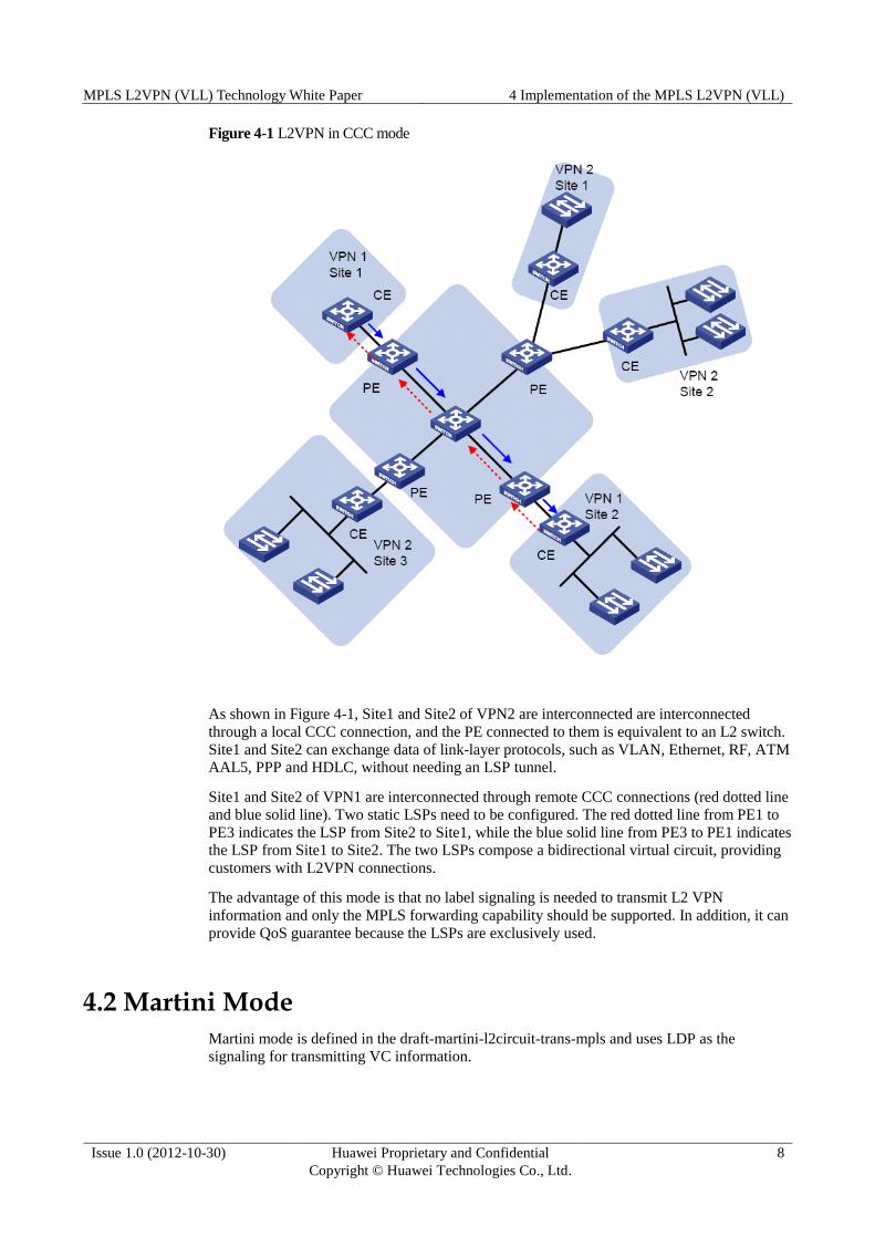
Figure 4-1 L2VPN in CCC mode
As shown in Figure 4-1, Site1 and Site2 of VPN2 are interconnected are interconnected
through a local CCC connection, and the PE connected to them is equivalent to an L2 switch.
Site1 and Site2 can exchange data of link-layer protocols, such as VLAN, Ethernet, RF, ATM
AAL5, PPP and HDLC, without needing an LSP tunnel.
Site1 and Site2 of VPN1 are interconnected through remote CCC connections (red dotted line
and blue solid line). Two static LSPs need to be configured. The red dotted line from PE1 to
PE3 indicates the LSP from Site2 to Site1, while the blue solid line from PE3 to PE1 indicates
the LSP from Site1 to Site2. The two LSPs compose a bidirectional virtual circuit, providing
customers with L2VPN connections.
The advantage of this mode is that no label signaling is needed to transmit L2 VPN
information and only the MPLS forwarding capability should be supported. In addition, it can
provide QoS guarantee because the LSPs are exclusively used.
4.2 Martini Mode
Martini mode is defined in the draft-martini-l2circuit-trans-mpls and uses LDP as the
signaling for transmitting VC information.
MPLS L2VPN (VLL) Technology White Paper 4 Implementation of the MPLS L2VPN (VLL)
Issue 1.0 (2012-10-30) Huawei Proprietary and Confidential
Copyright © Huawei Technologies Co., Ltd.
9
In Martini mode, a remote LDP session is established between PEs. The PE allocates a VC
label to each link and forwards the VC label to the remote PE through the LSP established by
LDP. In this way, a virtual circuit (VC) is established on the LSP.
Compared with the CCC mode, Martini mode cannot provide the local switching function, but
a single LSP can be shared by multiple VCs on the service provider’s network.
As shown in Figure 4-2, LSP1 and LSP2 are shared by the VCs between Site1 and Site2 of
VPN1, and the VCs between Site1 and Site2 of VPN2. On the ingress PE, the inner layer of
the data packet will be tagged with the VC label and then the outer label (stack) of the LSP
before the data packet enters the LSP. Upon arriving at the egress PE, the outer label (stack)
of the data packet is stripped off. The egress PE can tell from the VC label which VC the
packet came from. The egress PE then forwards the data packet to the correct CE.
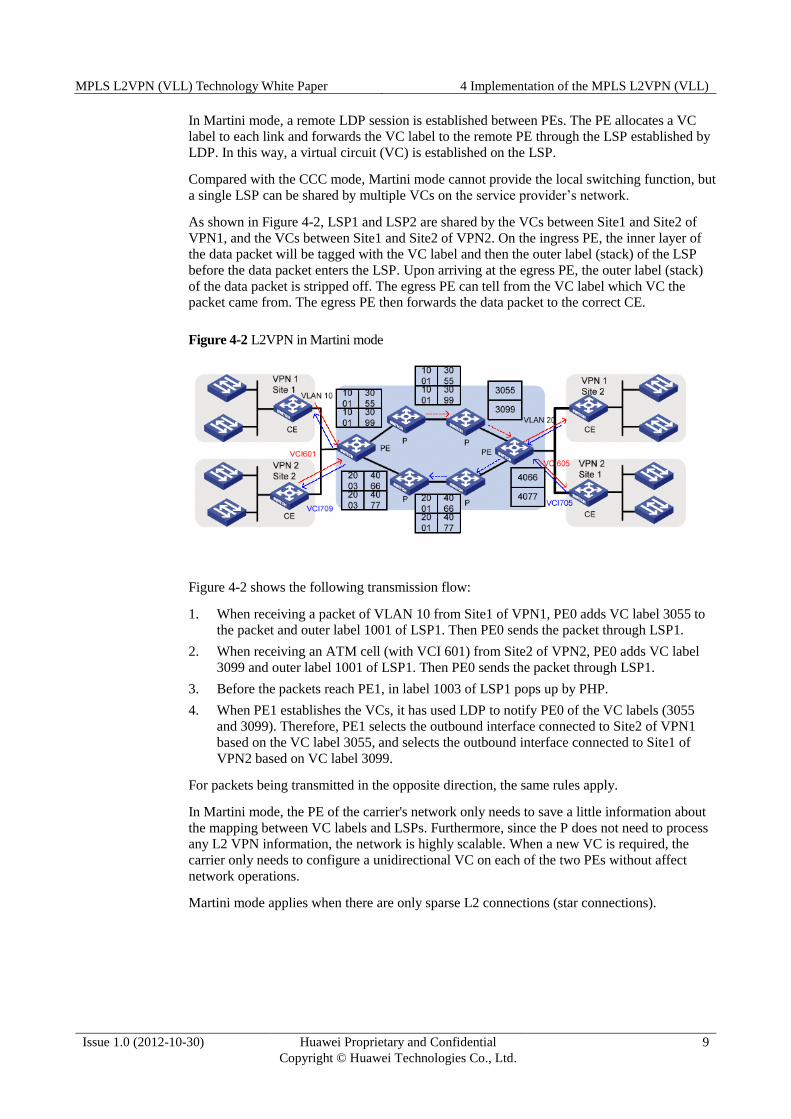
Figure 4-2 L2VPN in Martini mode
Figure 4-2 shows the following transmission flow:
1. When receiving a packet of VLAN 10 from Site1 of VPN1, PE0 adds VC label 3055 to
the packet and outer label 1001 of LSP1. Then PE0 sends the packet through LSP1.
2. When receiving an ATM cell (with VCI 601) from Site2 of VPN2, PE0 adds VC label
3099 and outer label 1001 of LSP1. Then PE0 sends the packet through LSP1.
3. Before the packets reach PE1, in label 1003 of LSP1 pops up by PHP.
4. When PE1 establishes the VCs, it has used LDP to notify PE0 of the VC labels (3055
and 3099). Therefore, PE1 selects the outbound interface connected to Site2 of VPN1
based on the VC label 3055, and selects the outbound interface connected to Site1 of
VPN2 based on VC label 3099.
For packets being transmitted in the opposite direction, the same rules apply.
In Martini mode, the PE of the carrier's network only needs to save a little information about
the mapping between VC labels and LSPs. Furthermore, since the P does not need to process
any L2 VPN information, the network is highly scalable. When a new VC is required, the
carrier only needs to configure a unidirectional VC on each of the two PEs without affect
network operations.
Martini mode applies when there are only sparse L2 connections (star connections).
MPLS L2VPN (VLL) Technology White Paper 4 Implementation of the MPLS L2VPN (VLL)
Issue 1.0 (2012-10-30) Huawei Proprietary and Confidential
Copyright © Huawei Technologies Co., Ltd.
10
4.3 Kompella Mode
The Kompella mode is defined in draft-kompella-ppvpn-l2vpn. Interior Border Gateway
Protocol (IBGP) sessions are established between PEs to detect L2VPN sites and transmit
VPN information through extended BGP between PEs.
In label distribution, MPLS L2VPN in Kompella mode uses the label block method. The size
of a label block is equal to the CE range (specified by the user), so multiple connections can
be allocated labels at one time. This mode allows users to allocate extra labels to VPNs for
reserved use and effectively simplifies VPN deployment and expansion. In Kompella mode,
VPNs are identified by VPN targets, as a result of which VPN networking is highly flexible.
Kompella mode is applicable to a variety of VPN network topologies.
In Kompella mode, VPNs are allocated on the entire service provider network, and CEs are
numbered in each VPN. To establish a connection between two CEs, you only need to set the
local and remote CE IDs on the PEs and to specify the VC ID allocated to the local CE.
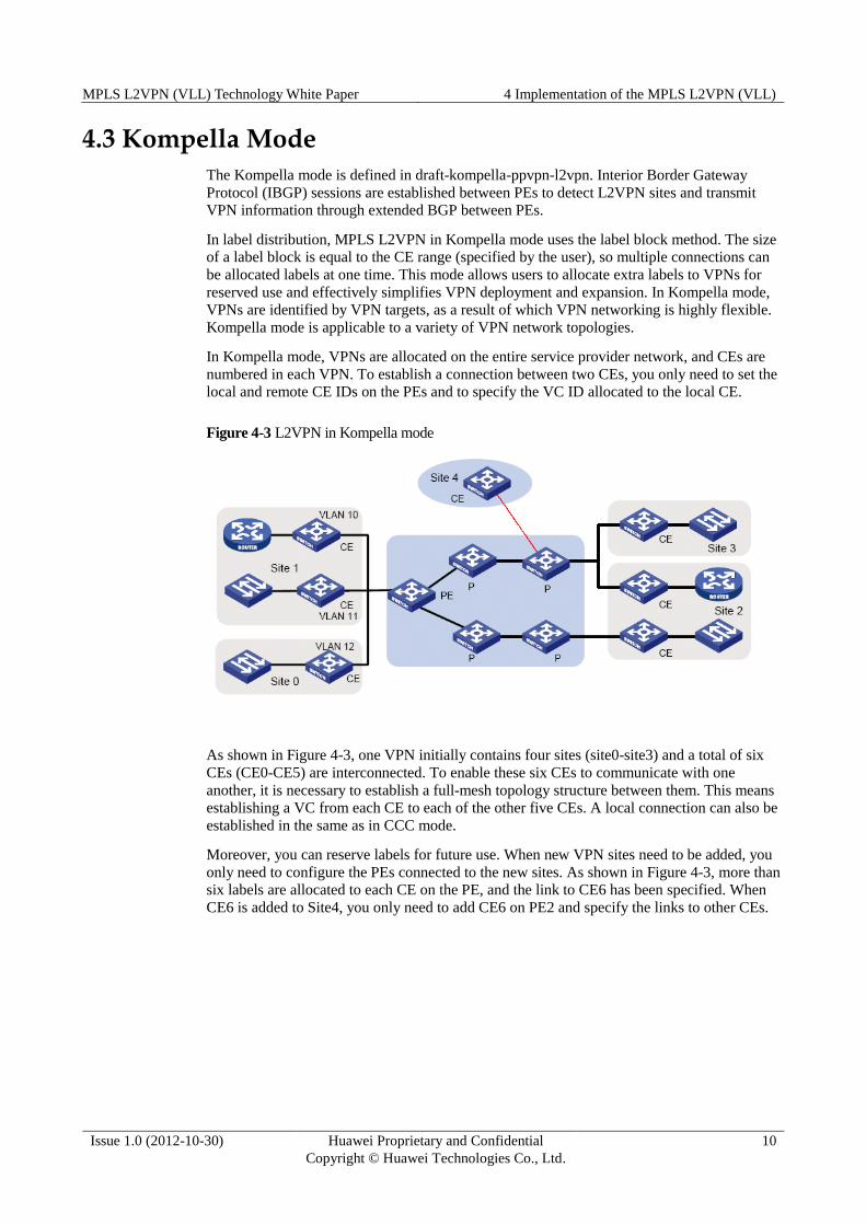
Figure 4-3 L2VPN in Kompella mode
As shown in Figure 4-3, one VPN initially contains four sites (site0-site3) and a total of six
CEs (CE0-CE5) are interconnected. To enable these six CEs to communicate with one
another, it is necessary to establish a full-mesh topology structure between them. This means
establishing a VC from each CE to each of the other five CEs. A local connection can also be
established in the same as in CCC mode.
Moreover, you can reserve labels for future use. When new VPN sites need to be added, you
only need to configure the PEs connected to the new sites. As shown in Figure 4-3, more than
six labels are allocated to each CE on the PE, and the link to CE6 has been specified. When
CE6 is added to Site4, you only need to add CE6 on PE2 and specify the links to other CEs.

MPLS L2VPN (VLL) Technology White Paper 5 VLL Application
Issue 1.0 (2012-10-30) Huawei Proprietary and Confidential
Copyright © Huawei Technologies Co., Ltd.
11
5 VLL Application
The Kompella mode applies to large enterprises with large sites, numerous routes, and simple
access mode. These enterprises require site-to-site QoS and have strong network management
capabilities. An enterprise that initially used leased lines or traditional VPN can smoothly
transition over to MPLS L2VPN services. The carrier can provide L2 links with a strict QoS
guarantee for the enterprise.
The Martini mode requires more complex configuration than the Kompella mode and is not
suitable for large-scale networks. The Martini mode is flexible and applicable to the intranets
of large enterprises or small carriers. This mode is oriented to LAN users and addresses the
Ethernet difficulties with long-distance transmission. Many Ethernet switch vendors support
this mode.
Figure 5-1 illustrates a typical application scenario. Carrier A has a nationwide backbone
network while Carrier B has customer networks in multiple cities. Carrier B may hope to rent
the bandwidth of Carrier A to interconnect its own networks in different places. Since Carrier
B has sufficient network management and maintenance capabilities, it may adopt the VLL
networking to prevent its private network routes from being released to other private
networks.
Figure 5-1 Integrated networking diagram


![vpn dienst 97.ppt [Kompatibilitätsmodus] - dfn.de · MPLS –MultiprotocolLabelSwitchingMultiprotocol Label Switching IP MPLS ... pseudowire-classl2vpnclass l2vpn encapsulation mpls](https://img.dokumen.tips/doc/110x75/5b06d42a7f8b9a58148d59db/vpn-dienst-97ppt-kompatibilittsmodus-dfnde-multiprotocollabelswitchingmultiprotocol.jpg)