Embed Size (px)
Citation preview

Copyright © 2001 Data Connection Limited. All Rights Reserved.
MPLS IN OPTICAL NETWORKS
An analysis of the features of MPLS and Generalized MPLS and their application to Optical Networks, with reference to the
Link Management Protocol and Optical UNI.
Version 2: October 2001
Neil Jerram MPLS Architect at Data Connection Ltd.
Adrian Farrel previously Development Manager of DC-MPLS
now Member of Technical Staff at Movaz Networks Inc. [email protected]
Data Connection Limited 100 Church Street
Enfield, UK Tel: +44 20 8366 1177
http://www.dataconnection.com
Copyright © 2001 Data Connection Limited. All Rights Reserved.
MPLS IN OPTICAL NETWORKS
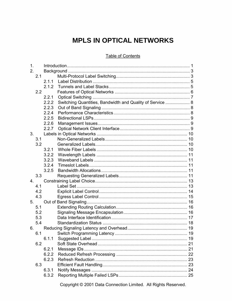
Table of Contents
1. Introduction.................................................................................................... 1 2. Background ................................................................................................... 3
2.1 Multi-Protocol Label Switching............................................................ 3 2.1.1 Label Distribution ............................................................................... 5 2.1.2 Tunnels and Label Stacks.................................................................. 5
2.2 Features of Optical Networks ............................................................. 6 2.2.1 Optical Switching ............................................................................... 7 2.2.2 Switching Quantities, Bandwidth and Quality of Service .................... 8 2.2.3 Out of Band Signaling ........................................................................ 8 2.2.4 Performance Characteristics.............................................................. 8 2.2.5 Bidirectional LSPs.............................................................................. 9 2.2.6 Management Issues........................................................................... 9 2.2.7 Optical Network Client Interface......................................................... 9
3. Labels in Optical Networks .......................................................................... 10 3.1 Non-Generalized Labels................................................................... 10 3.2 Generalized Labels........................................................................... 10
3.2.1 Whole Fiber Labels .......................................................................... 10 3.2.2 Wavelength Labels .......................................................................... 11 3.2.3 Waveband Labels ............................................................................ 11 3.2.4 Timeslot Labels................................................................................ 11 3.2.5 Bandwidth Allocations ...................................................................... 11
3.3 Requesting Generalized Labels........................................................ 11 4. Constraining Label Choice........................................................................... 13
4.1 Label Set .......................................................................................... 13 4.2 Explicit Label Control........................................................................ 14 4.3 Egress Label Control ........................................................................ 15
5. Out of Band Signaling.................................................................................. 16 5.1 Extending Routing Calculation.......................................................... 16 5.2 Signaling Message Encapsulation.................................................... 16 5.3 Data Interface Identification .............................................................. 17 5.4 Standardization Status ..................................................................... 18
6. Reducing Signaling Latency and Overhead................................................. 19 6.1 Switch Programming Latency ........................................................... 19
6.1.1 Suggested Label .............................................................................. 19 6.2 Soft State Overhead ......................................................................... 21
6.2.1 Message IDs .................................................................................... 21 6.2.2 Reduced Refresh Processing .......................................................... 22 6.2.3 Refresh Reduction ........................................................................... 23
6.3 Efficient Fault Handling..................................................................... 23 6.3.1 Notify Messages .............................................................................. 24 6.3.2 Reporting Multiple Failed LSPs........................................................ 25

Copyright © 2000 Data Connection Limited. All Rights Reserved. Page 2
6.3.3 State Removal on PathErr ............................................................... 26 7. Bidirectionality ............................................................................................. 28
7.1 Upstream Labels .............................................................................. 28 7.2 Confirming the Forward Path............................................................ 29
7.2.1 Delay at Terminator Node ................................................................ 30 7.2.2 ResvConf ......................................................................................... 30
7.3 The Need for Asymmetry.................................................................. 30 8. Link Management Protocol (LMP) ............................................................... 32
8.1 Control Channel Management.......................................................... 33 8.2 TE Links ........................................................................................... 34 8.3 Link Verification ................................................................................ 34 8.4 Link Property Summarization............................................................ 35 8.5 Fault Detection ................................................................................. 36 8.6 Authentication................................................................................... 37
9. Optical UNI .................................................................................................. 38 9.1.1 Peer Model....................................................................................... 38 9.1.2 Overlay Model.................................................................................. 38
9.2 UNI Services .................................................................................... 40 9.3 Addressing and Routing ................................................................... 40 9.4 Realization of UNI in GMPLS Protocols............................................ 41 9.5 LMP Extensions ............................................................................... 42
10. Summary ..................................................................................................... 43 11. Glossary ...................................................................................................... 44 12. References .................................................................................................. 46 13. About Data Connection................................................................................ 48

Copyright © 2001 Data Connection Limited. All Rights Reserved. Page 1 http://www.dataconnection.com
1. INTRODUCTION
Multi-Protocol Label Switching (MPLS) is growing in popularity as a set of protocols for provisioning and managing core networks. The networks may be data-centric like those of ISPs, voice-centric like those of traditional telecommunications companies, or a converged network that combines voice and data. At least around the edges, all these networks are converging on a model that uses the Internet Protocol (IP) to transport data.
Non-generalized MPLS overlays a packet switched IP network to facilitate traffic engineering and allow resources to be reserved and routes pre-determined. It provides virtual links or tunnels through the network to connect nodes that lie at the edge of the network. For packets injected into the ingress of an established MPLS tunnel, normal IP routing procedures are suspended; instead the packets are �label switched� so that they automatically follow the tunnel to its egress.
In their cores, however, most modern high-bandwidth networks do not switch packets. Instead, the bandwidth of the underlying optical fibers is parceled out by either frequency (wavelength) or time division multiplexing, and optical switches forward the data in these parcels by switching particular timeslots, wavelengths or wavebands, or even the contents of entire fibers. The result is more rapid throughput for application data, and with a guaranteed quality of service, but at the (minor) costs of the control traffic needed to setup and maintain bandwidth allocations, and of the possible waste in the event that an application does not use all the bandwidth that was reserved for it.
Traditionally, provisioning in optical networks has required manual planning and configuration resulting in setup times of days or even weeks and a marked reluctance amongst network managers to de-provision resources in case doing so impacts other services. Where control protocols have been deployed to provision optical networks they have been proprietary and have suffered from interoperability problems. With the success of MPLS in packet switched IP networks, optical network providers have driven a process to generalize the applicability of MPLS to cover optical networks as well, the result of which is the set of internet drafts that collectively describe �Generalized MPLS.� These drafts generalize
• the MPLS data forwarding model � such that it includes current practice in optical networks,
• the MPLS control protocols � so that they can be used as a standardized and interoperable way of provisioning optical networks.
Other, related work to standardize the management and configuration of optical networks is ongoing in the development of the Link Management Protocol (LMP) [8] and of optical extensions to OSPF.
This white paper discusses some of the technical challenges that have arisen in the process of applying MPLS to optical networks, and the technologies that have now been developed to address those challenges.
The rest of the paper is structured as follows.
• Section 2 gives more detailed background information on MPLS and optical networks. Readers who are already familiar with these areas may turn straight to section 3.

Copyright © 2001 Data Connection Limited. All Rights Reserved. Page 2 http://www.dataconnection.com
• Sections 3 through 9 discuss a range of specific challenges using MPLS in optical networks.
• Sections 10, 11 and 12 respectively provide a summary, list of references, and glossary of abbreviations used.
• Section 13 concludes with an outline of Data Connection, the authors of this white paper.

Copyright © 2001 Data Connection Limited. All Rights Reserved. Page 3 http://www.dataconnection.com
2. BACKGROUND
This section presents more detailed background information on MPLS and optical networks. Readers who are already familiar with these areas may happily skip straight to section 3.
2.1 Multi-Protocol Label Switching
Multi-Protocol Label Switching (MPLS) was developed as a packet-based technology and is rapidly becoming key for use in core networks, including converged data and voice networks. MPLS does not replace IP routing, but works alongside existing and future routing technologies to provide very high-speed data forwarding between Label-Switched Routers (LSRs) together with reservation of bandwidth for traffic flows with differing Quality of Service (QoS) requirements.
The basic operation of an MPLS packet-switched network is shown in the diagram below.
17
21 47
11Host X
Host Z
Host Y
LSR AIngress
LSR CEgress
LSR B
LSR DEgress
Fig.1: Two LSPs in an MPLS Packet-Switched Network
MPLS uses a technique known as label switching to forward data through the network. A small, fixed-format label is inserted in front of each data packet on entry into the MPLS network. At each hop across the network, the packet is routed based on the value of the incoming interface and label, and dispatched to an outgoing interface with a new label value.
Copyright © 2001 Data Connection Limited. All Rights Reserved. Page 4 http://www.dataconnection.com
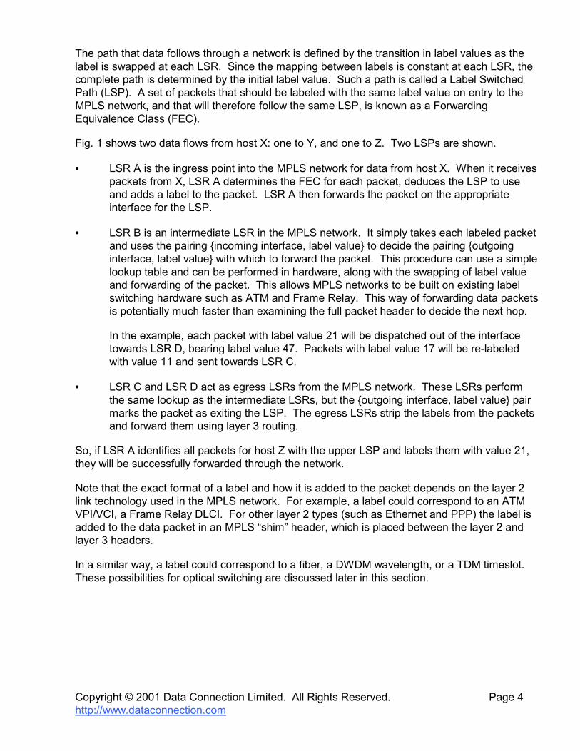
The path that data follows through a network is defined by the transition in label values as the label is swapped at each LSR. Since the mapping between labels is constant at each LSR, the complete path is determined by the initial label value. Such a path is called a Label Switched Path (LSP). A set of packets that should be labeled with the same label value on entry to the MPLS network, and that will therefore follow the same LSP, is known as a Forwarding Equivalence Class (FEC).
Fig. 1 shows two data flows from host X: one to Y, and one to Z. Two LSPs are shown.
• LSR A is the ingress point into the MPLS network for data from host X. When it receives packets from X, LSR A determines the FEC for each packet, deduces the LSP to use and adds a label to the packet. LSR A then forwards the packet on the appropriate interface for the LSP.
• LSR B is an intermediate LSR in the MPLS network. It simply takes each labeled packet and uses the pairing {incoming interface, label value} to decide the pairing {outgoing interface, label value} with which to forward the packet. This procedure can use a simple lookup table and can be performed in hardware, along with the swapping of label value and forwarding of the packet. This allows MPLS networks to be built on existing label switching hardware such as ATM and Frame Relay. This way of forwarding data packets is potentially much faster than examining the full packet header to decide the next hop.
In the example, each packet with label value 21 will be dispatched out of the interface towards LSR D, bearing label value 47. Packets with label value 17 will be re-labeled with value 11 and sent towards LSR C.
• LSR C and LSR D act as egress LSRs from the MPLS network. These LSRs perform the same lookup as the intermediate LSRs, but the {outgoing interface, label value} pair marks the packet as exiting the LSP. The egress LSRs strip the labels from the packets and forward them using layer 3 routing.
So, if LSR A identifies all packets for host Z with the upper LSP and labels them with value 21, they will be successfully forwarded through the network.
Note that the exact format of a label and how it is added to the packet depends on the layer 2 link technology used in the MPLS network. For example, a label could correspond to an ATM VPI/VCI, a Frame Relay DLCI. For other layer 2 types (such as Ethernet and PPP) the label is added to the data packet in an MPLS �shim� header, which is placed between the layer 2 and layer 3 headers.
In a similar way, a label could correspond to a fiber, a DWDM wavelength, or a TDM timeslot. These possibilities for optical switching are discussed later in this section.

Copyright © 2001 Data Connection Limited. All Rights Reserved. Page 5 http://www.dataconnection.com
2.1.1 Label Distribution
In order that LSPs can be used, the forwarding tables at each LSR must be populated with the mappings from {incoming interface, label value} to {outgoing interface, label value}. This process is called LSP setup, or Label Distribution.
The MPLS architecture document [4] does not mandate a single protocol for the distribution of labels between LSRs. In fact it specifically allows multiple different label distribution protocols for use in different scenarios. For a comparative analysis of two popular label distribution protocols, RSVP and CR-LDP, refer to the white paper MPLS Traffic Engineering: A Choice of Signaling Protocols [1] from Data Connection.
Alternatively, LSPs may be configured as �static� or �permanent� LSPs by programming the label mappings at each LSR on the path using some form of management such as SNMP control of the MIBs.
2.1.2 Tunnels and Label Stacks
A key feature of MPLS is that once the labels required for an LSP have been exchanged between the LSRs that support the LSP, intermediate LSRs transited by the LSP do not need to examine the content of the data packets flowing on the LSP. For this reason, LSPs are often considered to form tunnels across all or part of the backbone MPLS network. A tunnel carries opaque data between the tunnel ingress and tunnel egress LSRs.
In Fig.1, both LSPs are acting as tunnels. LSR B forwards the packets based only on the label attached to each packet. It does not inspect the contents of the packet or the encapsulated IP header.
Where LSPs are parallel they can be routed, together, down a higher-level LSP tunnel between LSRs in the network. Labeled packets entering the higher-level LSP tunnel are given an additional label to see them through the network, and retain their first-level labels to distinguish them when they emerge from the higher-level tunnel. This process of placing multiple labels on a packet is known as label stacking and is shown in Fig.2.
Label stacks allow a finer granularity of traffic classification between tunnel ingress and egress nodes than is visible to the LSRs in the core of the network, which route data solely on the basis of the topmost label in the stack. This helps to reduce both the size of the forwarding tables that need to be maintained on the core LSRs and the complexity of managing data forwarding across the backbone.
Copyright © 2001 Data Connection Limited. All Rights Reserved. Page 6 http://www.dataconnection.com
13
6 6
13
Host X
Host Y
LSR D
LSR A
LSR B
LSR ELSR C6
13
21
2117
17
BackboneNetwork
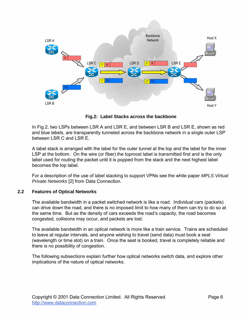
Fig.2: Label Stacks across the backbone
In Fig.2, two LSPs between LSR A and LSR E, and between LSR B and LSR E, shown as red and blue labels, are transparently tunneled across the backbone network in a single outer LSP between LSR C and LSR E.
A label stack is arranged with the label for the outer tunnel at the top and the label for the inner LSP at the bottom. On the wire (or fiber) the topmost label is transmitted first and is the only label used for routing the packet until it is popped from the stack and the next highest label becomes the top label.
For a description of the use of label stacking to support VPNs see the white paper MPLS Virtual Private Networks [2] from Data Connection.
2.2 Features of Optical Networks
The available bandwidth in a packet switched network is like a road. Individual cars (packets) can drive down the road, and there is no imposed limit to how many of them can try to do so at the same time. But as the density of cars exceeds the road�s capacity, the road becomes congested, collisions may occur, and packets are lost.
The available bandwidth in an optical network is more like a train service. Trains are scheduled to leave at regular intervals, and anyone wishing to travel (send data) must book a seat (wavelength or time slot) on a train. Once the seat is booked, travel is completely reliable and there is no possibility of congestion.
The following subsections explain further how optical networks switch data, and explore other implications of the nature of optical networks.

Copyright © 2001 Data Connection Limited. All Rights Reserved. Page 7 http://www.dataconnection.com
2.2.1 Optical Switching
In general, the point to point links between optical switches (OXCs) consist of bundles of optical fibers. An optical switch can choose to switch any possible subset of the optical bundle as a single unit � all the data traffic in such a unit on the incoming interface is switched to a corresponding type and size of unit on the outgoing interface.
The switching variants used in optical networks are described below. A key feature of all of them is that the OXC switches large flows of data as a unit, and does so based on quantities (wavelengths, time slots etc.) inherent in the network medium rather than by examining data headers at the individual packet or application level.
2.2.1.1 Switching Entire Fibers
The most obvious and basic quantity to switch is an entire fiber. All of the data that arrives on a single fiber is switched to be transmitted out of another fiber.
2.2.1.2 Lambda Switching
Within a single fiber, the available bandwidth can be divided up by frequency into wavelengths (also known as lambdas). An OXC could switch all of the data in wavelength A on the incoming fiber to wavelength B on the outgoing fiber. A restriction of some optical switches (e.g. MEMS) is that they are incapable of wavelength conversion, in which case B must be the same as A. Note that this is still different from switching the entire fiber, as two different wavelengths on a single incoming fiber could be switched to retain their wavelength values but exit the OXC on two different outgoing fibers.
2.2.1.3 Waveband Switching
Waveband switching is a generalization of lambda switching. If a fiber�s bandwidth is divided by frequency, wavelengths may be grouped together and switched as a block. This has potential benefits in reducing the number of LSPs in place, which saves on signaling and switching hardware. The process of switching a waveband can be viewed as an LSP tunnel that switches each of the payload wavelength LSPs in the same way.
Additionally, waveband switching may help to reduce the optical distortion that may be introduced by separating out and switching the individual lambdas.
2.2.1.4 Time Division Multiplexing
A fiber�s bandwidth can also be divided up by timeslots. In this model, the optical signal is seen as a sequence of data frames, with N frames each of size S traveling every second (making up the total fiber bandwidth N * S), and bandwidth is allocated for a particular data flow by reserving a portion of each frame.
The basic frame sizes, and the hierarchies by which a single frame can be divided up into timeslots, are the subject of several standards, notably SONET and SDH.

Copyright © 2001 Data Connection Limited. All Rights Reserved. Page 8 http://www.dataconnection.com
2.2.2 Switching Quantities, Bandwidth and Quality of Service
Switching quantities in optical networks are inextricably linked with bandwidth and quality of service. Bandwidth is determined exactly by the type and size of switching unit reserved (one fiber, one wavelength, one VC-4, ...). Quality of service boils down to this bandwidth together with complete reliability and very low burstiness/jitter.
Sections 3 and 4 of this paper discuss how optical switching quantities are interpreted and represented as Generalized MPLS labels, and how limitations on the types of switching that an OXC is physically able to perform translate into constraints on the selection of Generalized MPLS label values.
2.2.3 Out of Band Signaling
In non-generalized MPLS, label distribution for a particular data link is signaled �in band,� by sending control messages over the link which will carry the data.
In optical networks, on the other hand, there are strong reasons for completely separating control messages from data traffic, so that the signaling is �out of band.�
• Since all the data traffic passing through an OXC can be switched without reference to individual data packets, there is no need for the �data plane� part of the OXC to have any understanding of the protocol stacks (IP, TCP, UDP etc.) that are needed for the handling of control messages. In particular, it may not be necessary for OXCs to electronically terminate individual links.
• Between a pair of core OXCs there may be multiple data links. It could be both wasteful and confusing to establish a separate in band signaling session within each link. It is more efficient to manage the links as a group using a single out of band signaling session.
Typically, therefore, an optical switch completely separates its �control plane� from its �data plane,� and control connections to other switches go via a lower performance, non-optical network. The MPLS implications of this feature of optical networks are explored in section 5.
2.2.4 Performance Characteristics
One of the great flexibilities of MPLS networks is their ability to define a hierarchy of LSPs over which data is passed. This allows more transitory, low bandwidth LSPs, starting and finishing close to the network edge, to use pre-existing high bandwidth LSPs that span the core of a service provider network. The requirement for high bandwidth, long distance LSPs, coupled with their long lifetime, forms a natural fit with optical technologies. Consequently, it is a feature of LSPs in optical networks that they are typically long lived, and stable.
On the other hand, optically switched LSPs can be slow to set up when compared with electronically switched LSPs, because of the time needed to physically adjust micro mirrors and to wait for the resulting movement vibrations to damp away.

Copyright © 2001 Data Connection Limited. All Rights Reserved. Page 9 http://www.dataconnection.com
The stability and slow set up of optical MPLS networks have both influenced the development of Generalized MPLS. Section 6 discusses in detail how particular Generalized MPLS technologies take advantage of � or mitigate the effects of � these innate characteristics of optical networks.
2.2.5 Bidirectional LSPs
Trunks through the core of an optical network are typically bidirectional. Therefore there is a need for Generalized MPLS to set up bidirectional LSPs. Section 7 discusses the aspects of Generalized MPLS that relate to bidirectionality.
2.2.6 Management Issues
By their nature, the mechanisms that optical switches use to switch traffic flows � such as micro mirrors � do not notice if the traffic flow disappears altogether. Without additional hardware and software support, therefore, a break in the core of an optical network might not be detectable until the egress of that network, where the egress LSR tries to convert the signal back to packet form and finds it to be missing. This is known as the Loss Of Light (LOL) problem. Fault localization in an optical network requires that the switches can be asked, under management control, to check for LOL on their incoming fibers.
Conversely, in the case where an LSP is being torn down gracefully under control of a signaling protocol, the loss of light condition propagates along the fiber much more quickly than the signaling messages that inform each switch of the situation. In this situation, a downstream OXC that is capable of LOL detection should ideally be prevented from raising a false alarm about the signal loss.
Other management problems in an optical network include the communication between switches of information about how optical fiber bundles are addressed at either end of a link, and the setting up of backup links to take over in the event that a primary link fails. These management issues, and the corresponding aspects of Generalized MPLS and LMP that relate to them, are discussed in section 8.
2.2.7 Optical Network Client Interface
Currently, optical networks are mostly confined to network cores, with existing lower cost networking technologies bridging the gap between core and edge networks. Therefore an optical network needs to provide an interface to allow client network devices � such as routers � to dynamically request connections through it. Section 9 describes the Optical User-to-Network Interface (O-UNI), which meets this need.

Copyright © 2001 Data Connection Limited. All Rights Reserved. Page 10 http://www.dataconnection.com
3. LABELS IN OPTICAL NETWORKS
A basic requirement in MPLS is that the two LSRs at either end of a link agree on how they will mutually identify a traffic flow. For this purpose they use a label which is assigned by one of the LSRs and distributed to the other LSR using signaling protocol messages.
3.1 Non-Generalized Labels
In non-generalized MPLS, a label is a number (up to 32 bits) that gets written into the protocol header fields of data packets traveling on the link. Once a pair of LSRs have agreed this number, they also agree that the corresponding data flow consists of all data packets with this number in the appropriate protocol header field, and will switch all the packets in this flow in the same way.
Note that with this kind of label, the agreed label value does not necessarily imply a relationship to bandwidth allocation or quality of service for the corresponding data flow. The label value might not imply anything about how frequently packets with that value might arrive or what bandwidth is available.
Traffic Engineering label distribution protocols (such as RSVP and CR-LDP) facilitate quality of service and bandwidth negotiation as part of the label exchange. Other protocols (such as LDP) simply exchange labels.
3.2 Generalized Labels
The premise of Generalized MPLS is that the idea of a label can be generalized to be anything that is sufficient to identify a traffic flow. For example, in an optical fiber whose bandwidth is divided into wavelengths, the whole of one wavelength could be allocated to a requested flow � the LSRs at either end of the fiber simply have to agree on which frequency to use. Unlike with non-generalized labels, the data inside the requested flow does not need to be marked at all with a label value; instead, the label value is implicit in the fact that the data is being transported within the agreed frequency band. On the other hand, some representation of the label value is needed in the signaling protocol so that control messages between the LSRs can agree on the value to use.
Generalized MPLS extends the representation of a label from a single 32 bit number to an arbitrary length byte array and introduces the Generalized Label object (in RSVP) and Generalized Label TLV (in CR-LDP) to carry both the label itself and related information. The following subsections describe how the switching quantities used in optical networks are represented as GMPLS labels.
3.2.1 Whole Fiber Labels
A link between LSRs may consist of a bundle of optical fibers. LSRs may choose to allocate a whole fiber to a data flow and so simply need to agree on which fiber (within the bundle) to use. In this case the label value is the number of the selected fiber within the bundle. The interpretation of the fiber/port numbers is a local matter for the LSRs on the link. Where the two LSRs use different numbering schemes, LMP [8] provides a mechanism for LSRs to exchange and correlate numbering information � see section 8.

Copyright © 2001 Data Connection Limited. All Rights Reserved. Page 11 http://www.dataconnection.com
3.2.2 Wavelength Labels
Where the bandwidth of an optical fiber is subdivided by wavelength division multiplexing (WDM), an optical LSR may choose to allocate a single wavelength � or �lambda� � to a requested data flow. In this case the label value is the wavelength of the selected lambda.
3.2.3 Waveband Labels
If consecutive wavelengths are grouped together into a waveband, so as all to be switched in the same way, the label is a �waveband ID� and a pair of numbers (�channel identifiers�) indicating the lower and upper wavelengths of the selected waveband.
3.2.4 Timeslot Labels
Where the bandwidth of an optical fiber is subdivided into time slots by time division multiplexing (TDM), an optical switch may satisfy a particular data flow request by allocating one or more time slots to that flow. In general, therefore, a TDM label value must be sufficient to specify the allocated time slot(s). The exact details of TDM label representation depends upon the TDM hierarchy in use, for example SONET or SDH.
3.2.4.1 SONET/SDH Labels
A SONET/SDH label is represented as a sequence of five numbers, known as S, U, K, L and M, which select branches of the SONET/SDH TDM hierarchy at increasingly fine levels of detail.
3.2.5 Bandwidth Allocations
For all the types of Generalized MPLS label described here, the label value directly implies the bandwidth that is available for the corresponding data flow. For example, if a label denotes a single SONET VT-6 timeslot, the available bandwidth is, inextricably, the bandwidth of a VT-6 timeslot; similarly for other TDM labels and lambda, waveband or fiber labels. This is quite different from the case for non-generalized labels, and is a fundamental reflection of the nature of optical networks.
3.3 Requesting Generalized Labels
The basic MPLS protocol for agreeing a label value across a link is unchanged for optical networks.
• The upstream LSR sends a request to the downstream LSR (a Path message in RSVP, Label Request in CR-LDP). The request contains enough information about the requested bandwidth and quality of service for the downstream LSR to make a sensible label choice.
• The downstream LSR receives the request and allocates a label value that meets the requirements specified by the request.
• The downstream LSR sends a response to the upstream LSR (Resv in RSVP, Label Mapping in CR-LDP) that communicates the selected label value.

Copyright © 2001 Data Connection Limited. All Rights Reserved. Page 12 http://www.dataconnection.com
GMPLS generalizes the request setup message for two reasons: to distinguish it from a non-generalized request setup, and to allow it to carry additional parameters that specify the request in more detail. In RSVP this is done by using a Generalized Label Request object instead of a LABEL_REQUEST in the Path message, and in CR-LDP by adding a Generalized Label Request TLV to the Label Request message.
Some of the information that the downstream LSR needs in order to allocate a suitable label value is implied by the context. At the most basic level, both LSRs �know� that the label must be a generalized one, rather than, say, a non-generalized ATM label, because they �know� that the link to which the request applies is a generalized optical link. Therefore this information is not explicit in the request message.
However, since an optical link may consist of a bundle of fibers, and the switches may support more than one kind of multiplexing on those fibers, it is necessary for the upstream LSR to specify the �LSP encoding type� that it wants for the data flow being set up; this encoding type then determines whether the agreed label will be timeslot or wavelength based, and of what kind.
So the Generalized Label Request specified by GMPLS carries an LSP encoding type field. The currently supported values for this field that are relevant to optical networks are:
• ANSI PDH • ETSI PDH • SDH • SONET • Digital Wrapper • Lambda • Fiber.
Since some links may advertise (through the IGP) the capability to support more than one type of switching capability, the Generalized Label Request object/TLV contains a field that indicates the switching mode to be applied to the particular LSP. This allows, for example, a switch to be capable of switching whole fibers, wavebands or individual lambdas. The choice of how to switch for any particular LSP is made when the LSP is set up. This increases the flexibility of how the network resources can be used.
For fiber and wavelength based labels, nothing more is needed.
When requesting SONET and SDH labels, it may be necessary to request that the total bandwidth for the LSP should be split across multiple timeslots. Therefore, when the LSP encoding type is SONET or SDH, the Generalized Label Request carries additional fields that specify how many timeslots should be combined to meet the request (the �Requested Number of Components� or �RNC� field) and how those timeslots should be concatenated, including whether they are required to be contiguous (the �Requested Grouping Type� or �RGT� field).

Copyright © 2001 Data Connection Limited. All Rights Reserved. Page 13 http://www.dataconnection.com
4. CONSTRAINING LABEL CHOICE
As described in the previous section, the choice of label for each link is normally dictated by the downstream node on that link. In non-generalized MPLS, where labels are simply arbitrary numbers (e.g. ATM VPI/VCIs), this is fine. In Generalized MPLS, where labels are directly related to network resources, this can lead to conflicts during LSP set up.
For example, an optical switch based on micro-mirrors may be able to switch a received wavelength from an incoming port to an outgoing port, but may not be able to modify the wavelength.
Fig.3 shows two LSPs in an optical network where the switches (OXCs) are incapable of wavelength conversion. The blue LSP runs from an optical switch A through B, D and E to F. The red LSP runs from C through D and E to G. The colors also represent the wavelengths in use for the LSPs. There is no conflict on the link between D and E since the two LSPs use different wavelengths.
BOXC
EOXC
?COXC
DOXC
AOXC
FOXC
GOXC
?
Fig.3: Conflict of Labels at Optical Switches
However, when LSR C needs to set up a new LSP through D and E to G it must pick a new wavelength. If the choice is left to LSR G (which would be the normal way of processing in MPLS) G might choose blue. But blue is already in use between D and E and so cannot be used. If the choice is given to LSR C, a similar problem may occur.
There is therefore a need to allow all OXCs along the path to constrain and/or influence the choice of labels to ensure that appropriate labels are chosen.
4.1 Label Set
Generalized MPLS introduces the concept of a Label Set. An upstream LSR includes a Label Set on its signaling request to restrict the downstream LSR�s choice of label for the link between them. The downstream LSR must select a label from within the Label Set, or else must fail the LSP setup.
This is useful in the optical domain when, for example,
• an LSR is incapable of converting between wavelengths (as in the example above)

Copyright © 2001 Data Connection Limited. All Rights Reserved. Page 14 http://www.dataconnection.com
• an LSR can only generate and receive a subset of the wavelengths that can be switched by neighboring LSRs
• it is desirable for an LSR to limit the amount of wavelength conversion that it has to perform, in order to reduce the distortion on the optical signals.
The Label Set is constructed by including and/or excluding an arbitrary number of label lists and/or ranges. If no labels are explicitly included, the set consists of all valid labels not explicitly excluded. If no Label Set is present, the downstream LSR is not constrained in its choice of label.
As the Label Set is propagated on the Path message, each LSR may generate a new outgoing Label Set, based on its hardware capabilities and possibly on the incoming Label Set. For example, an LSR that is incapable of wavelength conversion generates an outgoing Label Set by forwarding the incoming Label Set, minus any labels that it cannot generate or receive. In contrast, an LSR that is capable of converting all wavelengths in an incoming Label Set may choose to remove the Label Set when sending the signaling request downstream, to indicate that it will accept any label for use on its downstream link.
Consider again the example in Fig.3. Suppose LSR C can only generate wavelengths from a range R. It therefore signals a Label Set of �anything in range R except red�. LSR D modifies this and signals �anything in range R except red or blue�. LSR E forwards this unchanged, and LSR G can select a color that will be acceptable to all of the LSRs in the path, if one is available.
Note that the color is not guaranteed to be acceptable. If LSR G chooses, say, green, another LSP B-D-C using green may have been set up while LSR D was waiting for the signaling response from LSR E. This risk can be reduced by also using Suggested Labels � see section 6.1.1.
4.2 Explicit Label Control
GMPLS also introduces Explicit Label Control. This enhances the MPLS concept of an explicit route by allowing the ingress LSR to specify the label(s) to use on one, some or all of the explicitly routed links for the forward and/or reverse path.
This is useful, for example, when the ingress LSR wants to insist that the wavelength used is the same along the whole LSP. This might be desirable in order to avoid distortion of the optical signal.
It may also be useful in Traffic Engineering where the path computation engine has knowledge of the labels in use in the network and the switching capabilities of the LSRs. In this case, the path can be computed to include the specific labels to be used at each hop.
Explicit labels are specified by the ingress LSR as part of the explicit route. At each LSR along the path, any explicit label that is specified in the explicit route for the next hop is removed and converted into a Label Set object, containing a single label, for the next hop. The LSR that receives this Label Set is then required to use this label for that hop (and must fail the set up if that label isn�t locally available).

Copyright © 2001 Data Connection Limited. All Rights Reserved. Page 15 http://www.dataconnection.com
4.3 Egress Label Control
When a network administrator initiates the setting up on an LSP, they are free to specify more or less strictly the path that the LSP should follow and optionally, as described in the previous subsection, the label values to use on the links that the LSP traverses.
Sometimes the network administrator may have additional information about the routing of data traffic as it emerges from the far end of the LSP. For example, they may know that only voice telephony traffic will be injected into this LSP, and that, upon exit from the LSP, all of this traffic should be routed via a telephony gateway with a well known address. In such cases, it makes sense to avoid the data packet examination and routing calculation that the egress LSP would otherwise have to perform by signaling the well known gateway address along the LSP.
The mechanism to achieve this is called egress label control. The administrator simply adds additional �label� objects to the explicit route after the last hop object. The encoded �labels� do not have to conform to any standard MPLS label format, but can be anything that makes sense to the egress LSR. When the egress LSR receives the LSP setup message, it notices the additional label objects at the end of the explicit route and interprets them in whatever way it finds useful.

Copyright © 2001 Data Connection Limited. All Rights Reserved. Page 16 http://www.dataconnection.com
5. OUT OF BAND SIGNALING
The non-generalized MPLS signaling protocols presume that the data traffic in an LSP will follow the same path as the signaling messages. In optical networks, however, the bandwidth granularity of channels in optical links is high, and it would be wasteful to use a whole bandwidth slice (time slot or wavelength) as a signaling channel. So there are strong reasons for the signaling to instead follow an �out of band� path, via a control channel that is physically distinct from the data channel. It also simplifies the technology that an optical switch needs to implement in its data plane, if the data plane does not need to understand the protocols upon which signaling messages are based.
Some solutions use a low bandwidth link (e.g. Ethernet) running in parallel to the data channel. Alternatively, it may be that the need to provision a dedicated signaling channel can be avoided by routing via an existing IP cloud.
Out of band signaling raises three key issues for the application of Generalized MPLS to optical networks.
• The routing that an optical LSR performs during LSP setup must be extended to calculate suitable distinct next hop IP addresses and outgoing interfaces for the data and signaling.
• Signaling messages may need to be encapsulated to ensure that they arrive successfully at the intended next hop LSR.
• Since signaling messages are no longer in band, they need a way of indicating the data interface to which they refer.
The following subsections explain these issues further, and how they are resolved.
5.1 Extending Routing Calculation
When an LSR on the data and signaling paths attempts to route the LSP setup, it must calculate two outgoing routes to the next hop, one via the data path, and one via the signaling path. The data path must be evaluated first and a signaling path must then be found that reaches the next hop on the data path.
The topologies for the signaling and data networks are obviously different, so the routing decision is complicated. Work is ongoing on optical extensions to OSPF that will permit distribution of topology data for both signaling and data networks. Once this data has been distributed, each individual LSR has the information that it needs to calculate the required routes for out of band signaled GMPLS.
5.2 Signaling Message Encapsulation
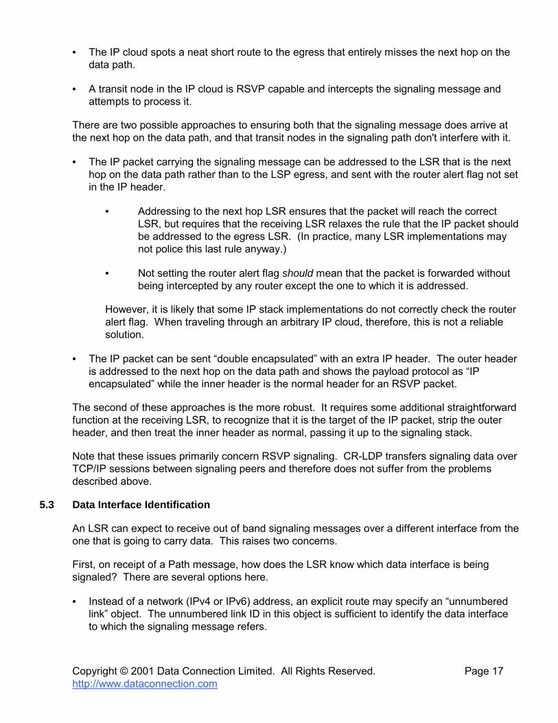
When running RSVP signaling, each signaling message is addressed to the egress (destination) LSR, never to the immediate next hop. Routers on the path intercept such messages by noticing that the �router alert� flag is set. With out of band signaling, there are two problems with this approach.
Copyright © 2001 Data Connection Limited. All Rights Reserved. Page 17 http://www.dataconnection.com
• The IP cloud spots a neat short route to the egress that entirely misses the next hop on the data path.
• A transit node in the IP cloud is RSVP capable and intercepts the signaling message and attempts to process it.
There are two possible approaches to ensuring both that the signaling message does arrive at the next hop on the data path, and that transit nodes in the signaling path don't interfere with it.
• The IP packet carrying the signaling message can be addressed to the LSR that is the next hop on the data path rather than to the LSP egress, and sent with the router alert flag not set in the IP header.
• Addressing to the next hop LSR ensures that the packet will reach the correct LSR, but requires that the receiving LSR relaxes the rule that the IP packet should be addressed to the egress LSR. (In practice, many LSR implementations may not police this last rule anyway.)
• Not setting the router alert flag should mean that the packet is forwarded without being intercepted by any router except the one to which it is addressed.
However, it is likely that some IP stack implementations do not correctly check the router alert flag. When traveling through an arbitrary IP cloud, therefore, this is not a reliable solution.
• The IP packet can be sent �double encapsulated� with an extra IP header. The outer header is addressed to the next hop on the data path and shows the payload protocol as �IP encapsulated� while the inner header is the normal header for an RSVP packet.
The second of these approaches is the more robust. It requires some additional straightforward function at the receiving LSR, to recognize that it is the target of the IP packet, strip the outer header, and then treat the inner header as normal, passing it up to the signaling stack.
Note that these issues primarily concern RSVP signaling. CR-LDP transfers signaling data over TCP/IP sessions between signaling peers and therefore does not suffer from the problems described above.
5.3 Data Interface Identification
An LSR can expect to receive out of band signaling messages over a different interface from the one that is going to carry data. This raises two concerns.
First, on receipt of a Path message, how does the LSR know which data interface is being signaled? There are several options here.
• Instead of a network (IPv4 or IPv6) address, an explicit route may specify an �unnumbered link� object. The unnumbered link ID in this object is sufficient to identify the data interface to which the signaling message refers.

Copyright © 2001 Data Connection Limited. All Rights Reserved. Page 18 http://www.dataconnection.com
• An explicit route may specify the label for the hop. It is conceivable that the label value could also encode the interface index to which the label applies. For example, the label could carry the port id in the top 16 bits and the lambda id in the lower 16 bits.
• The data interface may be communicated via some new signaling protocol object.
Second, the LSR needs to relax its explicit route processing rules so that it is acceptable for the top hop to refer to the data path and not the signaling path.
5.4 Standardization Status
The latest GMPLS drafts address some of the issues of out of band signaling.
• Data interface identification. This is supported by the Interface ID TLV, which can carry any combination of the following kinds of address.
• An IPv4 address.
• An IPv6 address.
• An IP address together with an interface identifier.
• An IP address together with an upstream component link identifier.
• An IP address together with a downstream component link identifier.
In Generalized RSVP-TE, this TLV is part of the IF_ID RSVP_HOP object, which replaces and extends the previously defined RSVP_HOP object.
In Generalized CR-LDP, this TLV forms the body of the new Interface TLV.
• Control plane link and node failure.
• Generalized RSVP-TE uses standard RSVP refresh mechanisms to synchronize state following a control plane link or node failure, but also
• defines a way to negotiate the maximum control plane recovery period
• reuses the Suggested Label object, to allow an upstream node to tell the recovered downstream node about the label values that it allocated before failure.
• Generalized CR-LDP uses the mechanisms already described in [13] to synchronize signaling state following a link failure.
This just leaves the issue of how to ensure delivery of RSVP-TE signaling messages to the next hop. (There is no corresponding issue for CR-LDP because CR-LDP uses TCP to send signaling messages.) Nothing is yet standardized on this question, but most current reports seem to favor the encapsulation approach, either IP in IP as described above, or Generic Routing Encapsulation (GRE) as described in RFC 2784.

Copyright © 2001 Data Connection Limited. All Rights Reserved. Page 19 http://www.dataconnection.com
6. REDUCING SIGNALING LATENCY AND OVERHEAD
The performance characteristics of optical networks are often quite different from the electronically switched packet networks for which MPLS was originally developed.
• The time needed to set up an optical LSP may be longer than for a corresponding packet switched LSP, because of the mechanics of optical switch hardware.
• On the other hand, optical networks are particularly stable � once an LSP through an optical network has been established, it is likely to stay established for a long time.
• Should an optical link fail, the discrepancy between the speed of the data path and the speed of signaling messages means that the standard MPLS error messages are not an efficient tool for reporting and recovering from the failure.
The following subsections explore how Generalized MPLS has evolved to take these performance characteristics into account and to work well with them.
6.1 Switch Programming Latency
The normal procedure for MPLS has the switch programmed when the signaling response is received. That is, the signaling request progresses through the network hop by hop from ingress to egress, the signaling response then travels from egress to ingress, causing the switch to be programmed as it goes. When the response reaches the ingress, the whole LSP is programmed and data may immediately start to flow.
Part of the reason for this way of doing things is that labels are allocated by the downstream node on each hop, easing contention issues. Hence, on each hop, the label is not known by that hop�s upstream LSR until the response is received.
Optical switches may be relatively slow to program. Although the time to select and adjust the switching components may be quite fast, the time taken for the components to settle down after programming can be much larger � measured in milliseconds. For example, a micro-mirror can be programmed quickly, but the mirror may take tens of milliseconds to stabilize and stop vibrating after it has been adjusted. It is not safe for an LSR to send a signaling response to its upstream neighbor while the mirror is still vibrating, as the ingress could then send data prematurely, and the data would be lost or incorrectly switched.
Therefore the time taken to establish an LSP that traverses n optical LSRs is
2*(end to end signaling time) + n*(switch programming and settling time)
The combination of optical switches and conventional MPLS causes considerable latency in LSP setup.
6.1.1 Suggested Label
To reduce the latency of LSP setup, GMPLS introduces the Suggested Label concept.

Copyright © 2001 Data Connection Limited. All Rights Reserved. Page 20 http://www.dataconnection.com
Each LSR selects a label which it believes will be suitable for use on the link between itself and its downstream partner. It signals this label on the forward signaling path and immediately starts to program its own switch on the assumption that this label is the one that will be agreed.
When the signaling response arrives back at the LSR the message carries a label. If this label confirms the choice suggested on the request, nothing further needs to be done because the switch is already programmed. As long as the switch programming has by now settled down, the signaling response can immediately be forwarded upstream. If the label is different from the one suggested on the signaling request, the switch must be reprogrammed, but nothing is lost compared with the base case where no label was suggested.
In the example in Fig. 4 a signaling request is received at an LSR. For the sake of the example, the signaling protocol is RSVP-TE so the message is a Path.
Path(Suggested Label = a)
OXC
Path(Suggested Label = b)
Resv(Label = c)Resv(Label = d)
Fig. 4: Label Suggestion
The Path message carries a Suggested Label object that indicates the label (λa) that the upstream LSR would like used on the segment of the LSP that links the two LSRs. The receiving LSR processes the Path as follows.
• It selects a label for use on the upstream link (λd). This should be the suggested label (λd = λa) if possible, but may be any other label.
• It selects a preferred label for use on the downstream link (λb). Depending on the properties of the switch this may be the same value as selected for the upstream interface (λd = λb) for example if the switch is not capable of wavelength modification.
• It sends a command to the switch fabric to begin programming the switch (λd x λb)
• It sends a Path message downstream containing the label that it would like used on the downstream segment (λb).
• At some point it receives a Resv from the downstream LSR. This indicates the actual label to use on the downstream segment (λc).
• If the actual label is different from the suggested label (λc ≠ λb), the switch must

Copyright © 2001 Data Connection Limited. All Rights Reserved. Page 21 http://www.dataconnection.com
• possibly pick a new value for the upstream label (λd) (this is necessary if the switch is not capable of wavelength conversion; it would therefore choose the same label as provided from downstream (λd = λc ≠ λa))
• send a command to the switch fabric to program the cross-connect (λd x λc)
• wait for the switch to be fully programmed and stable
• send a command to the switch fabric to deprogram the speculative cross-connect (λd x λb) as a background event.
• If the label is the label suggested (λc = λb), then no further programming is required, but the LSR must make sure that the programming request made earlier has completed satisfactorily.
• Finally, the LSR sends a Resv upstream indicating the actual label to use on the link (λd).
If everything has worked well and wavelength conversion is not possible, the suggested label from the original message is used on all messages (λa = λb = λc = λd). If there are any problems (for example, an actual label is unacceptable) the LSP is torn using the normal processes for the signaling protocol, and the switch is de-programmed.
6.2 Soft State Overhead
It is a feature of optical MPLS networks that they are typically stable, with LSPs being long-lived and relatively unchanging. This stability puts extra focus on the overhead of running RSVP, which requires regular refreshes between each network node to keep an LSP alive. The overhead of running this soft-state mechanism is more obvious in stable networks, because the benefit of automatically cleaning up expired state is less frequently needed. The following sections outline some approaches to reducing this overhead [14]. All the approaches are general to RSVP-TE, but have particular applicability to optical networks because of their stability.
Note that soft state overhead is not an issue for LDP and CR-LDP, since they are hard state protocols. The �other side of the coin� for LDP and CR-LDP is that they require special measures to preserve LSPs when a signaling session is temporarily broken [13].
6.2.1 Message IDs
The soft state nature of RSVP allows loss of protocol messages to be handled by simply waiting for the next refresh interval, or in the case of tear down messages waiting for the state to time out. A consequence of this is that there is a tension between choosing a short refresh interval, for robustness against message loss, and the increasing overhead of running RSVP that this entails.
Copyright © 2001 Data Connection Limited. All Rights Reserved. Page 22 http://www.dataconnection.com
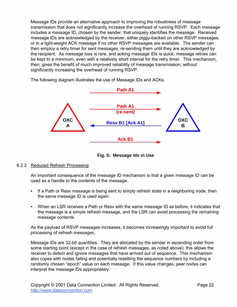
Message IDs provide an alternative approach to improving the robustness of message transmission that does not significantly increase the overhead of running RSVP. Each message includes a message ID, chosen by the sender, that uniquely identifies the message. Received message IDs are acknowledged by the receiver, either piggy-backed on other RSVP messages, or in a light-weight ACK message if no other RSVP messages are available. The sender can then employ a retry timer for sent messages, re-sending them until they are acknowledged by the recipient. As message loss is rare, and acking message IDs is quick, message retries can be kept to a minimum, even with a relatively short interval for the retry timer. This mechanism, then, gives the benefit of much improved reliability of message transmission, without significantly increasing the overhead of running RSVP.
The following diagram illustrates the use of Message IDs and ACKs.
Path A1
Resv B1 [Ack A1]
Path A1(re-sent)
Ack B1
OXCA
OXCB
Fig. 5: Message Ids in Use
6.2.2 Reduced Refresh Processing
An important consequence of the message ID mechanism is that a given message ID can be used as a handle to the contents of the message.
• If a Path or Resv message is being sent to simply refresh state in a neighboring node, then the same message ID is used again.
• When an LSR receives a Path or Resv with the same message ID as before, it indicates that the message is a simple refresh message, and the LSR can avoid processing the remaining message contents.
As the payload of RSVP messages increases, it becomes increasingly important to avoid full processing of refresh messages.
Message IDs are 32-bit quantities. They are allocated by the sender in ascending order from some starting point (except in the case of refresh messages, as noted above); this allows the receiver to detect and ignore messages that have arrived out of sequence. This mechanism also copes with nodes failing and potentially resetting the sequence numbers by including a randomly chosen �epoch� value on each message. If this value changes, peer nodes can interpret the message IDs appropriately.

Copyright © 2001 Data Connection Limited. All Rights Reserved. Page 23 http://www.dataconnection.com
6.2.3 Refresh Reduction
Message IDs provide a simple way to reduce the processing load on the receiver, by identifying refresh messages, but this still requires the sender to generate and send a complete RSVP message. Summary refresh (Srefresh) messages build on message IDs, and provide a way to reduce the load on the sender and network as well. The sender batches up previously sent message IDs for state that it wants to refresh in a neighboring node, which could be Path state, Resv state, or a mixture. The message IDs are then sent as a simple list in a dedicated Srefresh message.
On receipt of an Srefresh message, the receiver can quickly match the enclosed message IDs to its installed state, performing the normal keep alive action for each state that is matched.
• Matched message IDs are not acknowledged.
• Unmatched message IDs are returned to the sender as unacknowledged, in a NACK object. As with message ID acks, nacks can by piggy-backed on other RSVP messages, or sent in an ACK message if no suitable RSVP message is available.
• When the Srefresh sender receives a NACK object, it matches it to the local state that generated that message ID, and sends a full refresh message out immediately.
Srefresh provides a significant reduction in the overhead of running RSVP in stable networks, reducing the processing load on both sender and receiver, and reducing the bandwidth required to transmit regular refresh messages. By replacing multiple Path and Resv messages with a single Srefresh message, the bandwidth saving can be large.
While the reduction in the use of control channel bandwidth may not be important in optical networks where the control channel is often massively over-provisioned, the reduction in processing can be significant especially in large networks with very many LSPs.
Srefresh provides significant benefits for regular refresh messages, but can not be applied to trigger messages, where the full message contents are required. Message bundling provides some performance enhancement in these situations, by collecting the RSVP contents of several messages behind a single IP header. This saves some transmission bandwidth in IP (and possibly layer 2) headers, at the cost of some burstiness in transmission, and added latency as messages are collated. It can provide benefits in fail-over scenarios, where large numbers of tear down or set up messages are passing between neighbors.
6.3 Efficient Fault Handling
Recovery from failed network resources is an increasingly important aspect of network design. Ideally, the user should be protected from knowledge of a fault in the network. They should see no disturbance to their data traffic and should not have to take any remedial action.
MPLS offers many options for protecting LSPs from network problems. These are discussed at length in a white paper Surviving Failures in MPLS Networks [3] from Data Connection.
In optical networks, these procedures utilize some specific extensions to MPLS that are described below.

Copyright © 2001 Data Connection Limited. All Rights Reserved. Page 24 http://www.dataconnection.com
6.3.1 Notify Messages
Protection switching is a scheme where a network failure is recovered by directing data from an interrupted primary LSP onto a (typically pre-signaled) backup LSP that uses a disjoint path.
Primary LSPs
Backup LSPs
Notify Messages
Fig. 6: Protection Switching with Notify Messages
In Fig.6, the blue and pink lines represent primary LSPs through the network. When the link that they share in the middle of the network fails, data is re-directed to flow on the backup LSPs (shown in green).
In order for this to work, some upstream node (the repair point) must become aware that the error has occurred. The repair point is usually the ingress/initiator, and in non-generalized MPLS, the notification method is the PathErr message which flows upstream following the path of the LSP. This message flow is effective, but is slow because
• the path selected for the LSP may not be the shortest point between the detection point and the initiator (because of TE routing of the LSP), but the PathErr still follows this path delaying the notification of the error
• a PathErr message is intercepted and (minimally) processed at each LSR that it passes through which impacts the time taken to notify the initiator of the problem
• there may be very many affected LSPs all of which need PathErr messages sent at the same time � this can clog the network and consume important resources at the LSRs.

Copyright © 2001 Data Connection Limited. All Rights Reserved. Page 25 http://www.dataconnection.com
It is possible that an upstream node receiving the PathErr could incorrectly decide to take responsibility for the error, try to initiate local repair itself, and not forward the PathErr upstream until this had failed (or at all). This could introduce extremely large delays into the propagation of the error to a repair point.
GMPLS introduces a new message (to RSVP-TE only) to enhance this notification process. The Notify message is sent direct from the point of failure detection to the point of repair. In Fig.6, when the blue LSP fails, a Notify message is sent direct to the initiator. This message is sent direct to the initiator and does not have the IP router alert flag set so that it is not intercepted by transit nodes that are MPLS capable; it may optionally use IP double encapsulation. It uses regular IP routing to take the best route to the initiator.
If the LSP is bidirectional, a Notify message is also sent to the terminator to allow it to switch its data flow to the backup path. This message is sent by the node that detects the error on the terminator side of the failed link.
In fact, there is no reason why the repair points should be limited to the initiator and terminator LSRs. In Fig.6, the pink LSP is protected by a shorter backup segment (shown in green). An LSR that wants to be told about LSP failure adds an object containing its own address to the Path or Resv message as it passes through. This object specifically requests the use of Notify messages and identifies the recipient of the message. The Path message identifies the Notify recipient on the initiator side, and the Resv indicates the Notify recipient on the terminator side.
As the Path or Resv flows through the network, the LSRs may change the Notify recipient, and may even change whether or not a Notify is requested. This allows multiple repair points to be defined for an LSP.
Finally, it is possible that the most efficient use of Notify is to send it to a network device that can recalculate a path for the LSP and communicate it to the initiator using a management protocol (such as SNMP). In this case, the Notify recipient might be entirely distinct from the LSRs that make up the LSP.
6.3.2 Reporting Multiple Failed LSPs
As described above, one of the principal concerns with using PathErr to report LSP failures is that a single link failure may impact many LSPs with the need to send one PathErr message for each LSP. This could cause a data spike on the control channel and might cause temporary resource shortages in the LSRs that process the messages.
For this reason, the Notify message is defined so that it can report multiple LSPs at once. The only constraints are as follows.
• All failed LSPs on a single Notify message must have failed with the same reason code. Only one Error Spec is present and refers to all the reported LSPs.
• All failed LSPs on a single Notify must have the same Notify recipient (repair point).

Copyright © 2001 Data Connection Limited. All Rights Reserved. Page 26 http://www.dataconnection.com
6.3.3 State Removal on PathErr
RSVP specifies that errors are notified to upstream nodes using PathErr messages and to downstream nodes using ResvErr messages. When the ingress receives a PathErr it may
• ignore the error allowing state refresh to repair any damage • re-issue a Path message with different parameters that have a better chance of success • tear the reservation by sending PathTear.
This is somewhat inefficient after a serious failure since two message flows are needed (the PathErr flow and the PathTear flow).
Generalized MPLS introduces an option on a PathErr message to report that state has been removed at the sending node. That is, the flag indicates that the LSR that sent the PathErr has deprogrammed the switch for the LSP and has released all control blocks for the LSP.
The State Removed flag is applied on a hop-by-hop basis. When an LSR receives a PathErr with the flag set it must send a PathErr upstream. It may choose whether to set the flag on the PathErr that it sends. If it does not set the flag on the PathErr it sends, it may also choose to store the fact that it did receive the flag from the downstream LSR.
Notify
PathErr(State_removed)
PathErr
PathTear
PathErr
PathTearPathTear
PathErr(State_removed)
Fig. 7: Tearing state with PathErr
Fig.7 shows the flow of messages for a failed LSP. In the example, the node that detects the error sends a Notify message to the ingress and sends a PathErr upstream indicating that the state has been removed. The PathErr propagates upstream with the next two nodes not setting the State removed flag. Further upstream, an LSR decides to re-enable the State Removed flag and so also sends a PathTear downstream. Just one node away from the ingress, the PathErr traveling upstream meets a PathTear traveling downstream and no further processing is required.
Fig.8 shows how this feature can be useful to tidy up when the network is fragmented. Upstream of the LSP failure (the left hand side of the diagram), the processing is much as described for Fig.7. The combination of PathErr (with and without the State Removed flag set) and PathTear (triggered by the Notify or the PathErr) cause removal of state in a timely manner.

Copyright © 2001 Data Connection Limited. All Rights Reserved. Page 27 http://www.dataconnection.com
Downstream of the break, however, RSVP only provides for state removal through Path refresh timeouts. The LSR that detects the error might send Notify or ResvErr, and the egress might send ResvTear, but these exchanges do not fully remove the state or reservations at the intermediate nodes. Further, the PathTear sent by the ingress will never reach the LSRs downstream of the LSP failure if that failure affects the control path as well as the data path.
This situation can be remedied by using the State Removed flag on the PathErr message. When it receives the Notify message, the egress LSR can remove state, deprogram its switch and release reservations. It then sends the PathErr upstream indicating that it has removed state, and the fragmented LSP is tidied up.
Notify
PathErr(State_removed)
PathErrPathTear
PathErr
PathTear
PathErr(State_removed) (State_removed)
Notify
Fig. 8: Tidying up in a fragmented network

Copyright © 2001 Data Connection Limited. All Rights Reserved. Page 28 http://www.dataconnection.com
7. BIDIRECTIONALITY
Trunks through the core of an optical network often need to be bidirectional. That is, they need to be capable of carrying data in both directions.
In the original specification of MPLS, bidirectional connections required the set up of two unidirectional LSPs, and therefore coordination between the end points. This may have required that management messages were sent to both ends of the LSP requesting that the two directions be signaled by the two ingress nodes. This had the disadvantage of needing two signaling protocols (one for MPLS and one for the management messages) and could result in the two directions of the LSP following different paths through the network. It also left the end points with the need to invent a way of identifying and coordinating the two unidirectional LSPs that made up single bidirectional LSP.
An improvement was achieved using special processing at the egress of a unidirectional LSP to react to the receipt of a request for an LSP not just by sending a response, but also by sending a request in the opposite direction. With the use of route recording and explicit routing this allowed the two directions to follow the same path through the network, but still left co-ordination problems between the two directions of LSP.
Both of these solutions have the additional issue that four signaling messages are required (request and response in each direction) to set up the single LSP.
Generalized MPLS makes extensions to MPLS to address all of these issues and to allow a bidirectional LSP to be set up using a single message exchange. This has the benefit of requiring less signaling and achieves immediate co-ordination between the directions of flow.
For the sake of clarity, we define the head end of the LSP as the �initiator� and the tail end as the �terminator�. In a unidirectional LSP, the ingress is the initiator and the egress is the terminator. In a bidirectional LSP, the concepts of ingress and egress, and upstream and downstream are not clear since data flows in both directions, but as the LSP is originally requested from one place and responded from another, we can use the terms initiator and terminator without ambiguity.
7.1 Upstream Labels
Upstream Label is a new object introduced to LSP setup requests by GMPLS. It allows an �upstream� LSR to signal the label that should be used by the adjacent �downstream� LSR to forward data in the direction from terminator to initiator.
Fig.9 shows the exchange of signaling messages at an individual LSR. Again, RSVP is used as the example protocol.
• A Path message is received at the LSR. As described in a previous section, this message carries a Suggested Label which is used to pre-program the switch for the forward data path.

Copyright © 2001 Data Connection Limited. All Rights Reserved. Page 29 http://www.dataconnection.com
• The Path message also carries an Upstream Label. If the indicated label (λx) is not suitable for use at the LSR, it must reject the Path message (PathErr) at once. In this case, the PathErr message may include an Acceptable Label Set object to tell the upstream LSR which labels would have been successful � the upstream LSR may retry the Path message using a different Upstream Label chosen from the Acceptable Label Set, or may fail the LSP set up by propagating the PathErr further upstream.
• If the Upstream Label value is acceptable, the LSR selects a label (λy) to use as upstream label on the outgoing interface and signals this in the Upstream Label object of the Path message it sends out. If the switch is not capable of label modification, it will map the incoming upstream label value to the outgoing one (λy = λx)
• When the Path message reaches the LSP terminator and the switch there has been programmed, the reverse data path is complete and may be used immediately.
• The forward data path still has to be confirmed or reprogrammed as described before, and the Resv message is used to carry the forward path labels (λc and λd) back towards the initiator. When the Resv passes through the LSR, the switch ends up programmed as illustrated in the figure.
• Note that there is no mention of the Upstream Label on the Resv.
yx
d c
Path(Suggested Label = a ,Upstream Label = x) OXC
Path(Suggested Label = b,Upstream Label = y)
Resv(Label = c )Resv(Label = d)
Fig. 9: Bidirectional LSP setup
7.2 Confirming the Forward Path
One concern with the process described above is that the GMPLS specifications state that when the LSP setup request (Path message) reaches the terminator, the reverse data path must be considered to have been established, and data can immediately start to flow.

Copyright © 2001 Data Connection Limited. All Rights Reserved. Page 30 http://www.dataconnection.com
7.2.1 Delay at Terminator Node
In order to guarantee this, each LSR on the path might consider that it has to wait until its switch is fully programmed before it forwards the LSP setup request towards the terminator. This would result in slow LSP setup as each switch may take a considerable amount of time to stabilize. This defeats the purpose of label suggestion.
Alternatively, the LSRs on the path could simply forward the LSP setup request as soon as they have checked that programming the switch is likely to succeed, and continue with the programming in the background. This relies on several procedures.
• Prior to sending data, the terminator LSR must allow a small amount of time for other LSRs to become successfully programmed. This time might be no longer than it takes to program its own switch, but could be longer in a network made up of switches from different vendors.
• Programming errors at transit LSRs must be immediately reported as LSP failures, and the terminator LSR must be prepared to handle these error notifications even if they arrive ahead of the original programming request.
This approach allows the LSP setup time to converge on the unidirectional LSP setup time described above, but it requires shared knowledge and co-operation between the switch implementations at the transit LSRs.
7.2.2 ResvConf
A more secure solution is available in RSVP-TE and uses the ResvConf message. This message flows in the same direction as a Path message and confirms the receipt at the initiator of the Resv message. It is requested by the terminator by a flag on the Resv message.
The terminator can use this message to confirm that the switches at the transit nodes have been successfully programmed. In fact, the process would be that the Resv is not propagated towards the initiator by any LSR until it is happy that its switch is correctly programmed. When the Resv reaches the initiator it sends a ResvConf to the terminator (hop by hop) and data can flow in both directions.
This solution increases the number of signaling exchanges (three rather than two), but increases the stability of the signaling. The choice of this option is entirely up to the implementation of the terminator LSR and requires no additions to the RSVP protocol. This option is not available in CR-LDP.
7.3 The Need for Asymmetry
Given that Generalized MPLS supports both unidirectional initiator-to-terminator and bidirectional LSPs, it is natural to consider whether unidirectional reverse path LSPs, that is for data flow from the terminator back towards the initiator, would also be useful.

Copyright © 2001 Data Connection Limited. All Rights Reserved. Page 31 http://www.dataconnection.com
In fact they are. In a densely used network, populated mostly with bidirectional (symmetric) and unidirectional forward LSPs, it may simply not be possible to find a route for a new bidirectional data flow that has sufficient available resources for both LSP directions. In this scenario, the only solution may be to signal the forward and reverse halves of the desired LSP separately; the resulting combination is known as an �asymmetric� bidirectional LSP.
Asymmetric bidirectional LSPs can be set up using any of the pre-GMPLS methods that were used to set up symmetric bidirectional LSPs. In fact, one of the drawbacks of these methods (the difficulty in getting the two directions to follow the same path) is not an issue for asymmetric bidirectional LSPs. However, the issues of the need for a management and a signaling protocol still apply, and the problems of coordinating the forward and reverse halves of the LSP still exist.
Reverse path LSP signaling might also be achieved by reusing the Generalized MPLS support for bidirectional LSPs, with the (not yet standardized) understanding that so long as an Upstream Label is present, the Label Request and Label objects may be omitted from Path and Resv messages respectively. Given this understanding, an asymmetric bidirectional LSP, with the two LSP directions following different paths, can be set up by separately signaling the forward and reverse halves of the LSP. Note that practical network administration tools would tie the two halves of the asymmetric LSP together such that they can be managed as a single logical entity.

Copyright © 2001 Data Connection Limited. All Rights Reserved. Page 32 http://www.dataconnection.com
8. LINK MANAGEMENT PROTOCOL (LMP)
When Generalized MPLS is used to signal LSPs across core optical networks, a number of new management issues arise.
• Where most of the switches in an optical network are photonic, and therefore may not automatically spot Loss of Light, how can the precise location of a fault be localized?
• Where the link between two switches consists of a large bundle of optical fibers, how can the routing protocol be protected from having to advertise this huge number of links?
• With a large number of fibers, how can the neighboring devices agree how to address these links without manually configuring each node with the other�s link numbering scheme?
• Given that some channel session protocol is required to address these issues, what other features of this protocol are needed, e.g. to authenticate session peers and to detect interrupted sessions?
The Link Management Protocol (LMP) [8] has been evolved to address these issues. This section presents some of its features.
Between two nodes in an optical network, there may be multiple parallel optical data links that carry the data traffic. These data links may be
• electrically terminated at a node, in which case the node is always aware of the flow of data
• transparent, for example if a node is implemented using MEMS mirror technology, in which case the node cannot normally �see� the data flowing (although in many optical devices an optical tap can be used to check the data flow when necessary).
In the general case, as described previously in section 5, there is a separate control channel that is used for protocol exchange (out of band), although it is also possible for the protocol exchange to take place through one or more of the data links (in band). The fundamental job that LMP performs is to validate the �wiring� of the links between adjacent nodes, to validate that each of data links is operational, and to localize faults. Therefore LMP protocol exchange is only required between adjacent nodes that are directly connected by data links.
The IETF LMP specification covers the following areas of functionality. Some of these areas are optional within the protocol and do not need to be present in an LMP implementation. Each is described in greater detail in the following subsections.
• Control Channel Management. This covers the establishment, configuration and maintenance of an IP control channel between a pair of neighboring LMP nodes.
• Link Verification. This covers the verification of connectivity of data links, together with dynamic determination of the mapping between local and remote interface IDs. If link verification is not supported, these mappings must be provided by configuration.

Copyright © 2001 Data Connection Limited. All Rights Reserved. Page 33 http://www.dataconnection.com
• Link Property Correlation. This is confirmation between neighboring nodes that the mappings between local and remote interface IDs, and the aggregation of multiple data links into Traffic Engineering (TE) links are consistent.
• Fault Management. Light paths typically traverse multiple data links going from ingress to egress. When this light path fails, LMP provides a way to localize which data link has failed.
• Authentication. This provides cryptographic confirmation of the identity of the neighboring node.
8.1 Control Channel Management
Control Channel Management is concerned with negotiation and maintenance of the LMP session itself. LMP Hello messages are used to confirm that the session is still running. Parameter negotiation is necessary to agree values for per-session parameters such as Hello timeout periods, supported protocol level, and support for optional protocol features.
• Control Channel Selection is not currently within the scope of LMP, but nevertheless is an important requirement for LMP to work. LMP peers must know to use the same control channel(s) when they exchange LMP messages.
• Parameter Negotiation allows a pair of LMP nodes to converge on a mutually acceptable set of configuration parameters. The protocol exchange involves three message (Config, ConfigAck, ConfigNack) each of which can contain a variable number of sub-objects describing particular parameters (such as timeout values, and support for optional protocol elements). The results of the parameter negotiation process are agreement on timeout intervals for control channel maintenance and agreement on the supported set of LMP capabilities.
• Control Channel Maintenance involves an ongoing exchange of �Hello� messages between a pair of LMP nodes, to confirm that the control channel is still operational. Control channel failure can result in the transfer of LMP operations to a backup control channel. If no LMP control channel is up it is impossible to be sure of the state of the data links and LMP cannot collect any further information. The data links are marked as �degraded� and the signaling components can be warned that problems may occur and not be properly rectified. The signalling components could take remedial action such as re-routing the LSPs.

Copyright © 2001 Data Connection Limited. All Rights Reserved. Page 34 http://www.dataconnection.com
8.2 TE Links
Between a pair of optical switches there may be a large number of optical fibers. Since it is usually the case that several of these fibers have the same properties as far as routing protocols are concerned � i.e. same end points, quality of service etc. � it makes sense not to flood the routing database with duplicated information for each individual fiber. For routing purposes, therefore, fibers with the same properties are grouped together into a �TE link,� and only the TE link is advertised via routing.
However, if individual fibers are not known through routing information, GMPLS LSRs need a way of identifying individual fibers within a TE link, so that a signal switched into a fiber by the upstream LSR can be picked up by the downstream one. LMP meets this need by providing mechanisms for
• mapping the ID used at one end of an optical fiber to the ID used at its other end � link verification
• grouping sets of IDs at either end into the corresponding TE link ID � link summarization.
8.3 Link Verification
Link Verification has two purposes.
• Verification of data connectivity on particular data links.
• Automatic determination of the mapping between local and remote interface IDs for both data links and TE links.
In Generalized MPLS, LSRs use the interface ID mappings determined by LMP link verification to signal exactly which fiber of a TE link is the target for an LSP.
The link verification process involves a number of steps.
• The exchange of BeginVerify / BeginVerifyAck / BeginVerifyNack messages between the LMP nodes to initiate link verification. The BeginVerify message sent by the initiating node includes the ID of the TE link whose fibers it intends to test.
• The sending of Test messages down the links to be tested one after another, together with timer/retry processing. Note that this message is transmitted on the particular data link being verified, not sent via the normal IP control channel. The receiving node checks for light on each of the fibers that it believes make up its end of the specified TE link.
• The exchange of TestStatusFail / TestStatusSuccess / TestStatusAck messages to report the results of data link tests.
• The exchange of EndVerify / EndVerifyAck.
The results of the link verification process, illustrated in Fig. 10, are:
• determination which data links have tested successfully

Copyright © 2001 Data Connection Limited. All Rights Reserved. Page 35 http://www.dataconnection.com
• mappings between the local and remote interface IDs for the data links
• mappings between the local and remote interface IDs for the TE links.
Node A Node B
40
41
42
72
71
70
50
51
81
80
Local Remote OK? 40 72 Yes 41 71 Yes 42 70 No 50 81 Yes 51 80 Yes
Local Remote OK? 72 40 Yes 71 41 Yes 70 42 No 81 50 Yes 80 51 Yes
Fig. 10: Link Verification Table
8.4 Link Property Summarization
The main purpose of this function is to discover and agree between two adjacent LMP nodes on interface ID mappings and data link properties. This is achieved by the exchange of LinkSummary / LinkSummaryAck / LinkSummaryNack messages, each of which contains multiple sub-objects.
• TE Link sub-objects indicate the mappings between local and remote TE link IDs, together with other information about the TE links (such as protection and multiplex capability). Each TE Link aggregates multiple data links, indicated by the subsequent data link sub-objects.
• Data link sub-objects indicate the mappings between local and remote interface IDs (as determined by link verification or by manual configuration) together with information about the link type.
The results of the link property correlation process are:
• confirmation that the mappings between local and remote interface IDs are consistent between the LMP nodes (which is particularly important where the mappings have been pre-configured rather than dynamically determined via link verification)
• confirmation that the aggregation of data links into TE Links is consistent between the adjacent LMP nodes
• agreement on the properties and capabilities of the data channels.

Copyright © 2001 Data Connection Limited. All Rights Reserved. Page 36 http://www.dataconnection.com
The aggregation of data links into TE Links is illustrated in Fig. 11.
Node A Node B
40
41
42
72
71
70
50
51
81
80
Local Remote 20 30 21 31
20
21
30
31
Local Remote 30 20 31 21
Fig. 11: TE Link Mappings
8.5 Fault Detection
Many photonic optical switches are �transparent,� in the sense that they propagate the light signal without any interference. They can switch data by fiber, wavelength or time slot without needing to examine the actual signal at all. Consequently, if the signal disappears because of a fault somewhere upstream, the switch may simply not notice.
In the typical worst case, the absence of the signal is only detected when the needs to be converted back to electronic form for forwarding over a packet switched network. Then, the only information is that there is a fault on one of the optical links somewhere back up the LSP through which packets were expected to arrive.
LMP fault detection is used in this scenario to localize the link on which the fault occurred. It proceeds as follows.
• The process is initiated by the downstream node which first notices failure on a data link.
• This node sends a ChannelFailure message to its upstream neighbor for that link.
• The upstream node determines which incoming/upstream data link(s) connect to the failed outgoing/downstream data link
• If the corresponding incoming data link has also failed, then the upstream node responds with a ChannelFailureAck and propagates the fault detection process by sending a new ChannelFailure message to the next node upstream. Alternatively, this node might have noticed the LOL under its own steam and so have already propagated the ChannelFailure upstream.

Copyright © 2001 Data Connection Limited. All Rights Reserved. Page 37 http://www.dataconnection.com
• If the corresponding incoming data link has not failed, then the upstream node has localized the fault, responds to the downstream node with a ChannelFailureNack message, and reports the error locally.
The results of the process are:
• an indication that a particular data link has failed
• indication whether the failure has been localized to this node � precisely, to the downstream link at this node.
LMP also includes a mechanism for nodes to indicate when particular data links recover again, via the exchange of ChannelActive / ChannelActiveAck messages.
8.6 Authentication
Since the control channel between a pair of LMP nodes may pass through an arbitrary IP cloud, even the Internet, it is important to be able to authenticate the messages that are received over this channel.
To see why this is necessary, consider the denial of service that could be caused by sending a fake an LMP BeginVerify message to a core optical switch, to instruct it to begin verification of all its data links. If the link verification proceeded, normal data forwarding would be suspended for the duration of the testing.
Optionally, therefore, LMP sessions may negotiate the use of an MD5 hash algorithm to authenticate control messages. When authentication is agreed, each control message is signed by adding to it a 16 byte signature calculated from a shared secret key and an MD5 hash of the message contents.

Copyright © 2001 Data Connection Limited. All Rights Reserved. Page 38 http://www.dataconnection.com
9. OPTICAL UNI
The Generalized MPLS extensions provide a way to use MPLS for provisioning in optical networks. In a real-world network, optical networking equipment is typically used at the center of the network, providing a high capacity, fast backbone service for client devices that use existing lower cost, lower bandwidth, networking technologies (e.g. IP routers or ATM switches). This section seeks to answer the question that arises, how do the packet or MPLS networks request services from the Time Slot or Lambda switched optical transport network? There are two main possibilities, with others acting as hybrids between the two, the peer model and the overlay model.
9.1.1 Peer Model
GMPLS
Router XC XC
LMP
Router
Fig. 14: GMPLS Peer Model
In the peer model, the same signaling protocol (GMPLS) is used to set up the whole path, including both the packet and transport elements, with the client�s requests being spliced into the requests needed to set up the internal tunnel. Whilst this has the advantage of providing a single management layer to the Service Provider, there are some significant considerations:
• The Service Provider may wish to keep topology information of the optical core private.
• Much of the equipment available for the optical core today uses proprietary signaling rather than GMPLS.
• Service Providers may wish to keep the paths set in the transport core as stable as possible, managed on a overall network basis for protection and restoration purposes. Thus they would not want the service requests of the packet network to be fulfilled automatically.
9.1.2 Overlay Model
In this model the optical and packet networks are managed independently and may potentially be signaled by different protocols. One solution is for the optical transport network (OTN) to provide a User-to-Network Interface (UNI) that allows client network devices to request connections across it dynamically.

Copyright © 2001 Data Connection Limited. All Rights Reserved. Page 39 http://www.dataconnection.com
Optical TransportNetwork
UNI
UNI
UNI
UNI
UNI
Client Network
Client Network
Fig. 12: The OTN and UNI Access
A signaling protocol needs to be defined to bridge the UNI.
Control channel(out-of-band)
UNI-C UNI-C
UNI-N UNI-N
UNI GMPLS /Proprietary Signaling
UNI
UNI LMP LMP UNI LMP
MPLS /other
protocol
MPLS /other
protocol
Fig. 13: OIF UNI Overlay Model
An internal tunnel between endpoint UNI-N nodes is set up using either GMPLS or some proprietary signaling mechanism. This tunnel can be provisioned ahead of time, or on demand in response to the client request. The data path between the client nodes is then set up by overlaying it upon this internal tunnel.
For the remainder of this section we will look at the requirements and specifications of this Optical UNI.

Copyright © 2001 Data Connection Limited. All Rights Reserved. Page 40 http://www.dataconnection.com
9.2 UNI Services
The client and OTN edge nodes that support UNI are not traditional signaling peers, in that the OTN service provider agrees a contract (in the billable sense!) with the client to provide a certain level of service across the network. A UNI message from client to OTN is best viewed as a request for service.
Given the contractual angle, it is important for there to be a defined method for identifying and authenticating clients across the UNI. This allows the OTN to check that a client�s account is in good standing before granting a connection request. For billing and auditing purposes, the OTN may also need to keep track of the connection by assigning a connection identifier that is valid beyond the lifetime of the connection and returning this to the client.
In order to set up a connection, a client needs to discover what services are available from the OTN and, that done, signal its requirements across the UNI. The types of service parameters signaled across the UNI are
• requested bandwidth of the connection
• class of service (e.g. the network restoration/protection strategy required)
• diversity (discussed below)
• data plane specific characteristics (e.g. for SONET/SDH, port, transparency and concatenation information).
A fundamental requirement of UNI is that clients are not allowed access to OTN internal addresses or topology information. This means that UNI connection requests are not allowed to specify explicit routes. The �Diversity� parameter allows a UNI client to request that a new connection follows a different route to a set of previous connections without requiring internal knowledge of the OTN. This is necessary to allow the client to request a disjoint backup to a primary route.
9.3 Addressing and Routing
A client requesting a connection across an OTN needs to identify the endpoints of the connection � the source (itself) and destination � using some addressing scheme.
The O-UNI solution is to use a new, distinct address space for UNI clients. In this strategy, the OTN assigns a single, globally unique address to each client endpoint. We refer to this type of address as a transport network assigned address, or TNA address.
Using an addressing scheme that is decoupled from both OTN internal and client protocol addresses has the following benefits.

Copyright © 2001 Data Connection Limited. All Rights Reserved. Page 41 http://www.dataconnection.com
• Internal OTN addresses are not revealed across administrative boundaries. Instead, clients address each other using TNA addresses, and mapping between the assigned address and internal switch addresses is done within the bounds of the OTN. (The alternative � revealing internal OTN addresses outside the OTN boundary � is seen as a significant security risk.)
• The OTN can organize the TNA address to maximize the efficiency of routing and reachability calculations for its clients.
• By decoupling TNAs from client addresses, UNI can provide a seamless way for clients using different protocols to interwork.
At the same time, use of TNAs imposes certain responsibilities on the clients and OTN.
• Clients must register with the OTN to be assigned a TNA.
• The OTN must provide an address resolution service, which translates between a remote client protocol address and a remote TNA address.
• The OTN must be capable of distributing TNA address client mappings and reachability information to all edge nodes that provide the UNI (intra-domain).
• Different OTNs must be capable of distributing addressing information between them (inter-domain).
One rejected addressing strategy was to use client protocol addresses. The key disadvantage of this strategy was that clients of the OTN are likely to use a variety different address spaces and formats (e.g. NSAP, IPv4, IPv6, e.164), which leads to number of difficulties
• The OTN has no control over these address spaces, so cannot organize them to facilitate routing (e.g. via hierarchies and summarization).
• Clients that need to interconnect to other clients using different protocols would need to be capable of translating between multiple address formats.
• Within a single address format, two client networks may use addresses that clash (e.g. in the case of VPNs). This means that a client address on its own may not actually be a unique identifier.
9.4 Realization of UNI in GMPLS Protocols
Although UNI is not a standard GMPLS peer-to-peer relationship, the signaling function required by UNI is very close to that achieved by the existing GMPLS signaling protocols RSVP and CR-LDP. (Although in practice, as with GMPLS, RSVP is well ahead in terms of current implementation.) With a few extensions to support the �UNI special� features such as TNA addressing, diversity, and connection identification, these protocols can be used for UNI signaling.
Similarly, the various link management and service discovery functions carried out by client and OTN UNI neighbors can be achieved by an extended flavor of LMP (see section 8).

Copyright © 2001 Data Connection Limited. All Rights Reserved. Page 42 http://www.dataconnection.com
The mapping between the standard and UNI flavors of the protocols are non-trivial, so an edge node for a GMPLS-provisioned OTN needs to be capable of running UNI across some interfaces and standard optical signaling across others.
The Optical Internetworking Forum (OIF) has produced a specification document describing how existing protocols can be extended to provide UNI functionality. The OIF UNI currently covers SONET/SDH connections and includes a wide range of protocol features discussed in this white paper, including
• RSVP, LDP and LMP with UNI extensions • UNI TNA addressing • out of band signaling • bidirectional LSPs • label set • reduced refresh processing • setup confirmation.
9.5 LMP Extensions
In addition to the standard LMP features described in section 8, OIF UNI defines two LMP extensions.
• In-Band Control Channel Bootstrap is a way of initiating in-band control channel communication when the IP address of a neighboring node is not known. The idea is that, when a control channel is realized in-band over a data link, an OIF UNI LMP node can send its initial LMP Config message to the �All Nodes� multicast address rather than to a specific unicast IP address. This allows an LMP node to automatically determine the IP address to use when communicating with its neighbor.
• Service Discovery is a way for UNI client and network nodes to discover each other�s UNI capabilities via the exchange of ServiceConfig, ServiceConfigAck and ServiceConfigNack messages. Using this mechanism,
• a UNI client node indicates its support for port-level attributes such as link type, signal type and transparency
• a UNI network node indicates its support for particular signaling protocols, transparency and monitoring, and network diversity.
Copyright © 2001 Data Connection Limited. All Rights Reserved. Page 43 http://www.dataconnection.com
10. SUMMARY
Optical networking is an important and challenging domain for development and experimentation using the Generalized MPLS protocols. Conversely, use of Generalized MPLS and LMP is a major step forward for optical network providers who have historically been troubled by interoperability problems resulting from non-standardized control and management protocols.
The application of Generalized MPLS to optical network has thrown up a number of interesting technical challenges. This paper has described some of those challenges and presented explanations and examples of how those challenges can be addressed in practice, and in particular how aspects of the Generalized MPLS protocol have evolved so as to meet those challenges.

Copyright © 2001 Data Connection Limited. All Rights Reserved. Page 44 http://www.dataconnection.com
11. GLOSSARY
AS: Autonomous System. A part of the network under a single administration and usually running a single routing protocol for internal routing.
CR-LDP: Constraint-based Routed Label Distribution Protocol. Extensions to LDP to set up Traffic Engineered LSPs, as defined in the Internet Draft �Constraint-based LSP Setup using LDP� [9].
DLCI: Data Link Circuit Identifier. The labels used in Frame Relay that are equivalent to MPLS labels.
DWDM: Dense Wavelength Division Multiplexing.
FEC: Forwarding Equivalence Class. A logical aggregation of traffic that is forwarded in the same way by an LSR. A FEC can represent any aggregation that is convenient for the SP. FECs may be based on such things as destination address and VPN Id.
GMPLS: Generalized MPLS [5, 6, 7]. Extensions to the MPLS Traffic Engineering signaling protocols to support additional features such as optical networks, bidirectional LSPs, and ingress control over labels and links.
IETF: Internet Engineering Task Force. The worldwide grouping of individuals from the computing and networking industry and from academia that devises and standardizes protocols for communications within the Internet. Responsible for the development of MPLS.
IP: Internet Protocol. A connectionless, packet-based protocol developed by the IETF and at the root of communications within the Internet.
LDP: Label Distribution Protocol. A protocol defined [10] by the IETF MPLS working group for distributing labels to set up MPLS LSPs.
LER: Label Edge Router. An LSR at the edge of the MPLS network. LERs typically form the ingress and egress points of LSP tunnels.
LMP: Link Management Protocol. A protocol under development by the IETF to discover and manage links, and to detect and isolate link failures.
LSP: Label Switched Path. A data forwarding path determined by labels attached to each data packet where the data is forwarded at each hop according to the value of the labels.
LSP Tunnel: A Traffic Engineered LSP capable of carrying multiple data flows.
LSR: Label Switching Router. A component of an MPLS network that forwards data based on the labels associated with the data.
MPLS: Multi-Protocol Label Switching. A standardized technology that provides connection-oriented switching based on IP routing protocols and labeling of data packets.

Copyright © 2001 Data Connection Limited. All Rights Reserved. Page 45 http://www.dataconnection.com
OEO: Opto-Electronic Switch. Short for Optical-Electronic-Optical, this switch terminates each optical connection converting the signal to electronics before forwarding packets to other optical links. Compare with PXC.
OTN: Optical Transport Network. A network whose underlying transport is optically based.
OXC: Optical Cross-Connect. An optical switch, either an OEO or a PXC.
PXC: Photonic Cross-Connect. A type of switch which is capable of switching and forwarding optical signals without needing to convert the signals to electronics. Compare with OEO.
Refresh message: A Path or Resv message sent to keep state alive in a neighboring node, and that is identical to a previous message in all but its integrity object.
RSVP: Resource ReSerVation Protocol (RFC 2205) [11]. A setup protocol designed to reserve resources in an Integrated Services Internet. RSVP has been extended to form RSVP-TE.
RSVP-TE: Extensions to RSVP to set up Traffic Engineered LSPs [12]. Throughout this document, RSVP-TE is referred to simply as �RSVP�.
TCP: Transmission Control Protocol. A transport level protocol developed by the IETF for reliable data transfer over IP.
TDM: Time Division Multiplexing. Partitioning the available bandwidth of an optical fiber by dividing it up into time slots.
TE: Traffic Engineering. The process of balancing the load on a network by applying constraints to the routes which individual data flows may take.
TNA: Transport Network Assigned [address]. An address assigned to a client end point by a UNI provider.
Trigger message: Any RSVP message that creates, updates, or deletes state (i.e. is not a refresh message).
UDP: Unreliable Datagram Protocol. A transport level protocol developed by the IETF for unreliable data transfer over IP, and used by RSVP.
UNI: (Optical) User to Network Interface. Interface by which an (optical) network client and provider can contractually agree services.
VPI/VCI: Virtual Path Identifier / Virtual Channel Identifier. The labels used in ATM layer 2 networks that are equivalent to MPLS labels.
VPN: Virtual Private Network. A private network provided by securely sharing resources within a wider, common network.
WDM: Wavelength Division Multiplexing. Partitioning the available bandwidth of an optical fiber by dividing it up into frequency bands.

Copyright © 2001 Data Connection Limited. All Rights Reserved. Page 46 http://www.dataconnection.com
12. REFERENCES
The following documents are referenced within this white paper. All RFCs and Internet drafts are available from www.ietf.org. URLs are provided for other references.
Note that all Internet drafts are �work in progress� and may be subject to change, or may be withdrawn, without notice.
1 White paper from Data Connection (www.dataconnection.com)
MPLS Traffic Engineering: A Choice of Signaling Protocols � Analysis of the similarities and differences between the two primary MPLS label distribution protocols: RSVP and CR-LDP
2 White paper from Data Connection (www.dataconnection.com)
MPLS Virtual Private Networks � A review of the implementation options for MPLS VPNs including the ongoing standardization work in the IETF MPLS Working Group
3 White paper from Data Connection (www.dataconnection.com)
Surviving Failures in MPLS Networks � An examination of the methods for protecting MPLS LSPs against failures of network resources
4 RFC 3031 Multiprotocol Label Switching Architecture
5 draft-ietf-mpls-generalized-signaling Generalized MPLS � Signaling Functional Description
6 draft-ietf-mpls-generalized-rsvp-te Generalized MPLS Signaling � RSVP-TE Extensions
7 draft-ietf-mpls-generalized-cr-ldp Generalized MPLS Signaling � CR-LDP Extensions
8 draft-ietf-ccamp-lmp Link Management Protocol (LMP)
9 draft-ietf-mpls-cr-ldp Constraint-Based LSP Setup using LDP
10 RFC 3036 LDP Specification
11 RFC 2205 Resource ReSerVation Protocol (RSVP) � Version 1 Functional Specification
12 draft-ietf-mpls-rsvp-lsp-tunnel RSVP-TE: Extensions to RSVP for LSP Tunnels
13 draft-ietf-mpls-ldp-ft Fault Tolerance for LDP and CR-LDP
14 RFC 2961 RSVP Refresh Overhead Reduction Extensions

Copyright © 2001 Data Connection Limited. All Rights Reserved. Page 47 http://www.dataconnection.com
In addition, a few other Internet drafts for MPLS may be of interest.
draft-fredette-lmp-wdm Link Management Protocol (LMP) for DWDM Optical Line Systems
draft-ietf-ccamp-gmpls-sonet-sdh GMPLS Extensions for SONET and SDH Control
draft-bala-mpls-optical-uni-signaling Signaling Requirements at the Optical UNI
draft-yu-mpls-rsvp-oif-uni RSVP Extensions in Support of OIF Optical UNI Signaling
draft-ietf-mpls-ldp-optical-uni LDP Extensions for Optical User Network Interface (O-UNI) Signaling

Copyright © 2001 Data Connection Limited. All Rights Reserved. Page 48 http://www.dataconnection.com
13. ABOUT DATA CONNECTION
Data Connection Limited (DCL) is the leading independent developer and supplier of MPLS, ATM, SS7, MGCP/Megaco, SSCTP, VoIP Conferencing, Messaging, Directory and SNA portable products. Customers include Alcatel, Cabletron, Cisco, Fujitsu, Hewlett-Packard, Hitachi, IBM Corp., Microsoft, Nortel, SGI and Sun.
Data Connection is headquartered in London UK, with US offices in Reston, VA and Alameda, CA. It was founded in 1981 and is privately held. During each of the past 19 years its profits have exceeded 20% of revenue. Last year sales exceeded $35 million, of which 95% were outside the UK, mostly in the US. In 1999 the company received its second Queen's Award for outstanding export performance.
The DC-MPLS and DC-LMP product families provide OEMs with a flexible source code solution with the same high quality architecture and support for which Data Connection�s other communications software products are renowned. They run within Data Connection�s existing high performance portable execution environment (the N-BASE). This provides extensive scalability and flexibility by enabling distribution of protocol components across a wide range of hardware configurations from DSPs to line cards to specialized signaling processors. It has fault tolerance designed in from the start, providing hot swap on failure or upgrade of hardware or software.
DC-MPLS and DC-LMP are suitable for use in a wide range of IP switching and routing devices including LSRs and LERs. Support is provided for a range of label distribution methods including RSVP-TE, CR-LDP and LDP. The rich feature set gives DC-MPLS the performance, scalability and reliability required for the most demanding MPLS applications, including core optical switches. Data Connection has been at the forefront of development of many of the features of Generalized MPLS. DC-MPLS is in use in a range of optical switches that will be deployed in the center of the World�s biggest and most strategic networks.
DC-MPLS integrates seamlessly with Data Connection�s ATM, SS7, MGCP and other converged network software products, and uses the same proven N-BASE communications execution environment. The N-BASE has been ported to a large number of operating systems including VxWorks, Linux, OSE, pSOS, Chorus, Nucleus, Solaris, HP-UX and Windows NT, and has been used on all common processors including x86, i960, Motorola 860, Sparc, IDT and MIPS. Proprietary OSs and chipsets can be supported with minimal effort.
Adrian Farrel was originally Architect and Development Manager for the DC-MPLS product family, and contributed to the GMPLS drafts in the IETF. He is now a Member of Technical Staff with Movaz Networks Inc.
Neil Jerram is lead designer for several of the optical enhancements in DC-MPLS and DC-LDP.
Data Connection is a trademark of Data Connection Limited and Data Connection Corporation. All other trademarks and registered trademarks are the property of their respective owners.