Embed Size (px)
Citation preview
International Journal of Science and Research (IJSR) ISSN: 2319-7064
Impact Factor (2018): 7.426
Volume 8 Issue 2, February 2019
www.ijsr.net Licensed Under Creative Commons Attribution CC BY
MPLS BSED VPN Implementation in Corporate
Environment
Shradha Khandare1, S.J.Nandedkar
2
1PG student, Electronics and Telecommunication Engineering, Maharashtra Institute of Technology, Aurangabad, India
2Assistant Professor, Electronics and Telecommunication Engineering, Maharashtra Institute of Technology, Aurangabad, India
Abstract: Multiprotocol label switching has become a key technology in today’s Ip technology for service providers and corporations
that prefer to use remote connectivity. Enterprise are attracted towards service providers which provide MPLS VPNs. It has large
number of customers due to the certain advantages over other VPN technologies like Frame Relay and ATM. Due to the unique
features possessed by MPLS VPN, such as VoIP by Cos, scalable bandwidth, voice and data on a single platform through various
sources, today MPLS VPN has become the leading technology IP technology. The main objective of this thesis was to develop an
understanding of the nature of MPLS VPN technology. The MPLS VPN technology is described briefly, and a network scenario is
illustrated to examine the different communication protocols. The practical part was carried out in a GNS3 simulator. For the practical
purpose, 3700 series router is used.
Keywords: MPLS VPN, Qos, ATM, Frame Rely
1. Introduction
Nowadays many new technologies are developed to make our
life easy. Enterprises and companies use these technologies
to make their service easy and cost efficient. We can access
and acquire any services from the internet distantly from
anywhere. Employers provide a flexible work environment to
their employees who could do their work staying at home or
anywhere in this world.
Due to better reliability and increased performance,
Multiprotocol Label Switching (MPLS) replacing another
WAN technologies. In the past different technologies like
Frame Relay, ATM, T1 or E1 dedicated links were used for
WAN connectivity. To maintain the security issues, layer2
VPNs were used in enterprise network that are not scalable.
The MPLS VPN provides scalability and can divide larger
enterprises into smaller networks. It became very useful in IT
enterprises that have to provide isolated networks to their
departments. Large enterprises are interested in MPLS VPN
since it provides a new option for WAN connectivity.
The main purpose of this paper is to discuss the
implementation of MPLS VPN technology. This paper
includes mainly the configuration needed for the
establishment of MPLS VPN and explains how to implement
a MPLS VPN over an IP4 network. The paper also explains
the benefits of MPLS VPN over traditional IP routing and
examines MPLS VPN network, protocols used for
communication and illustrate a network scenario.[1]
2. Multiprotocol Label Switching
2.1 Overview of MPLS
Multiprotocol Label Switching (MPLS) IS AN ip technology
developed by IETF to overcome the drawbacks of traditional
IP routing. MPLS is technique used by service providers to
provide better and single network infrastructure for real time
traffic such as voice and video. In the past Frame Relay and
ATM were used to transfer data in enterprise. MPLS operates
in between the data link layer and network layer, So it is
called layer 2.5 protocols.[3] MPLS works with Internet
Protocol (IP), Frame-Relay and Asynchronous Transport
Mode (ATM) network protocols to create a Label Switch
Path (LSP). It provides scalability to VPNs.
Each router in a traditional IP technology makes their
forwarding decision based on the study of packet’s header
and the result of the routing algorithm running in the network
layer. Whenever the packets arrive at the router, it has to
think where to send the packet. However, in MPLS every
packet assigned to forwarding equivalence class (FEC) as a
label that is used to make the forwarding decision without IP
lookups in every node. Every router has a table that indicates
how to handle FEC type of packets. Once the packet enters
the network, subsequent routers use this label as an index to
forward the packet with the help of table present in every
router.
2.2 Benefits of MPLS
Multi-service Networks: The ability to implement multi-
service networks is one of the main reasons behind the
popularity of MPLS. It helps the network to carry all
kinds of traffic. MPLS integrates different technologies,
such as Layer2 VPNs, Layer3 VPNs, Traffic
Engineering, QoS, GMPLS, and IPv6 which enables to
develop scalable and secure networks that guarantee
Service Level Agreement (SLA).
MPLS Virtual Private Network (MPLS VPN): - It
provides private and secure networks called virtual
private networks (VPN) over the same network topology
to many customers. Large enterprises and service
providers are interested in MPLS VPN due to its ability
to divide network to smaller networks and scalability
feature.
Paper ID: ART20194921 10.21275/ART20194921 230
International Journal of Science and Research (IJSR) ISSN: 2319-7064
Impact Factor (2018): 7.426
Volume 8 Issue 2, February 2019
www.ijsr.net Licensed Under Creative Commons Attribution CC BY
Scalability: In the past, most of the networks used to
have a core ATM switches surrounded by routers that
were totally meshed and had many adjacent networks.
The MPLS network helped to fix this kind of problem.
The core devices are not involved in any relationship
with the other networks, and their task is only to switch
packets.
Traffic Engineering: Traffic engineering is the ability to
control the traffic that helps to use the network
infrastructure optimally by spreading the traffic more
evenly over the all available links.
2.3 MPLS Operation
Instead of the IP address or MAC address or MAC address,
MPLS works on small labels. These labels are inserted
between layer 2 and layer 3 of OSI. Forwarding decisions are
based on these labels instead of having to look at complex IP
tables. Thus, it reduces the overhead and makes forwarding
decisions more efficient. The important considerations are
MPLS is layer 2.5 it gives speed of layer 2 and dynamics of
layer 3 technologies. The interesting factor is its flexibility of
use as completely layer 2 or layer 3 technologies. In MPLS
VPN it is solely used as layer 3 technology making labels
based on IP address. While, in case of VPLS, It makes labels
based on MAC address, making it is a layer 2 technology.
Thus the adaptability of MPLS makes it charismatic for
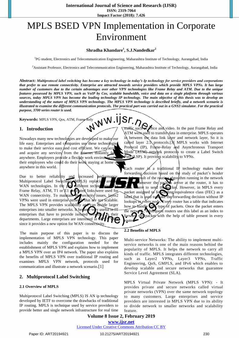
professionals. The MPLS label position in different types of
technologies can be seen in figure 1.
It can be seen from figure 1 that MPLS label stack is inserted
between IP header (layer 2) and corresponding layer 2
header of the particular technology. In case of MPLS based
VPN the label stack consists of a MPLS label at the top and
CPN label at the bottom. The size of label is 32 bit long as
shown in figure 2. The field is 20 bit long label value. Labels
are represented in decimal format. The second field is
experimental bits. These 3 bits are reserved for experiments.
1 bit long set (s) is kept 1 if it is the last label in number
otherwise kept 0. The last field of Time to Live (TTL)
comprises 8 bits and is used to count the number of hops.
2.4 MPLS terminologies
It is important to know before the configuration it has no
connection to customer sites and is deployed only in ISP
networks.
Figure 1: MPLS label Position indifferent technologies
Figure 2: MPLS Label Format
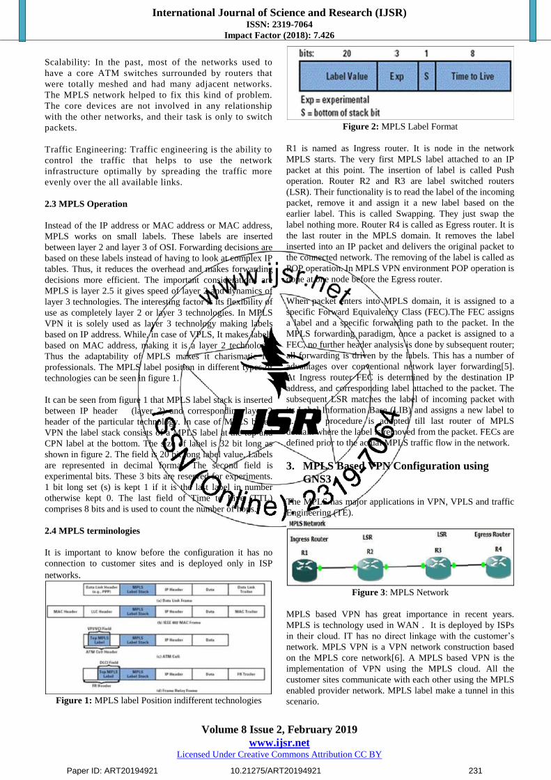
R1 is named as Ingress router. It is node in the network
MPLS starts. The very first MPLS label attached to an IP
packet at this point. The insertion of label is called Push
operation. Router R2 and R3 are label switched routers
(LSR). Their functionality is to read the label of the incoming
packet, remove it and assign it a new label based on the
earlier label. This is called Swapping. They just swap the
label nothing more. Router R4 is called as Egress router. It is
the last router in the MPLS domain. It removes the label
inserted into an IP packet and delivers the original packet to
the connected network. The removing of the label is called as
POP operation. In MPLS VPN environment POP operation is
done at one node before the Egress router.
When packet enters into MPLS domain, it is assigned to a
specific Forward Equivalency Class (FEC).The FEC assigns
a label and a specific forwarding path to the packet. In the
MPLS forwarding paradigm, once a packet is assigned to a
FEC, no further header analysis is done by subsequent router;
all forwarding is driven by the labels. This has a number of
advantages over conventional network layer forwarding[5].
At Ingress router FEC is determined by the destination IP
address, and corresponding label attached to the packet. The
subsequent LSR matches the label of incoming packet with
its Label Information Base (LIB) and assigns a new label to
it. Same procedure is adopted till last router of MPLS
domain where the label is removed from the packet. FECs are
defined prior to the actual MPLS traffic flow in the network.
3. MPLS Based VPN Configuration using
GNS3
The MPLS has major applications in VPN, VPLS and traffic
Engineering (TE).
Figure 3: MPLS Network
MPLS based VPN has great importance in recent years.
MPLS is technology used in WAN . It is deployed by ISPs
in their cloud. IT has no direct linkage with the customer’s
network. MPLS VPN is a VPN network construction based
on the MPLS core network[6]. A MPLS based VPN is the
implementation of VPN using the MPLS cloud. All the
customer sites communicate with each other using the MPLS
enabled provider network. MPLS label make a tunnel in this
scenario.
Paper ID: ART20194921 10.21275/ART20194921 231
International Journal of Science and Research (IJSR) ISSN: 2319-7064
Impact Factor (2018): 7.426
Volume 8 Issue 2, February 2019
www.ijsr.net Licensed Under Creative Commons Attribution CC BY
The configuration is carried out on the Graphical Network
Simulator-3 (GNS3). It is a GUI- based open source network
simulator. The task is implemented in a cisco environment.
The scenario is in figure 4.
Routers; Cisco 3745
IOS Version: 12.4
Router R1- R5 constitutes the MPLS network. It is also
called the provider’s network. MPLS is running on this
network. In the context of MPLS VPN, routers R1, R2 and
R5 are called Provider Edge (PE) routers. They are the
devices that have direct connectivity with a customer’s
network.
Whereas routers R6-R9 are called Customer Edge (CE)
routers. They are gateways of customer’s network and only
device having connectivity with an ISP’s network. The whole
customer’s network is called C-network.
Configuration at CE devices; At CE devices no special
configuration is required. The only requirement is to assign
IP addresses to interfaces and enable any IGP to carry the
customer routes to connected PE devices.
Configurations at PE devices; In the context of MPLS VPN,
most important configuration are done in PE devices. All the
parameters should be configured carefully to establish the
VPN connectivity. One of the most important parameters is
the configuration of virtual Routing and Forwarding (VRF)
instances. Inside, VRFs Route Distinguishers (RD) and route
targets (export/imports) are defined.
RD is the unique ID given to a particular VPN site. It must
be unique in the whole network, as a customer site is defined
based on RD. It is a 64 bit long address and mainly has three
formats which are used to assign RDs to a customer site by
ISP’s as shown in figure 5.To established connectivity to a
particular customer site, route targets exposed from one VRF
must be imported into the VRF of another customer site and
Vice versa.
PE-CE routing; PE-CE routing that achieved by using a BGP
protocol. Any another Interior Gateway Protocol (IGP) like
RIP, EIGRP or static routing can be used instead of BGP. If
we use any another IGP, then we have to redistribute the
routes from IGP to MP-BGP to share the VPN routes among
the PE devices. This increases the complexity in
configuration at PE devices. Hence, BGP is used because it
shares the routes by default with MP-BGP and no routes re-
distribution is required.
Provider network OSPF is configured as routing protocol in
the provider network. The MPLS is enabled on all provider
network routers. MPLS labels are assigned based on all
provider network routers. MPLS labels are assigned based on
routers of OSPF MPLS doesn’t work without a routing
protocol in a network. It can work with any IGP running in
the network.
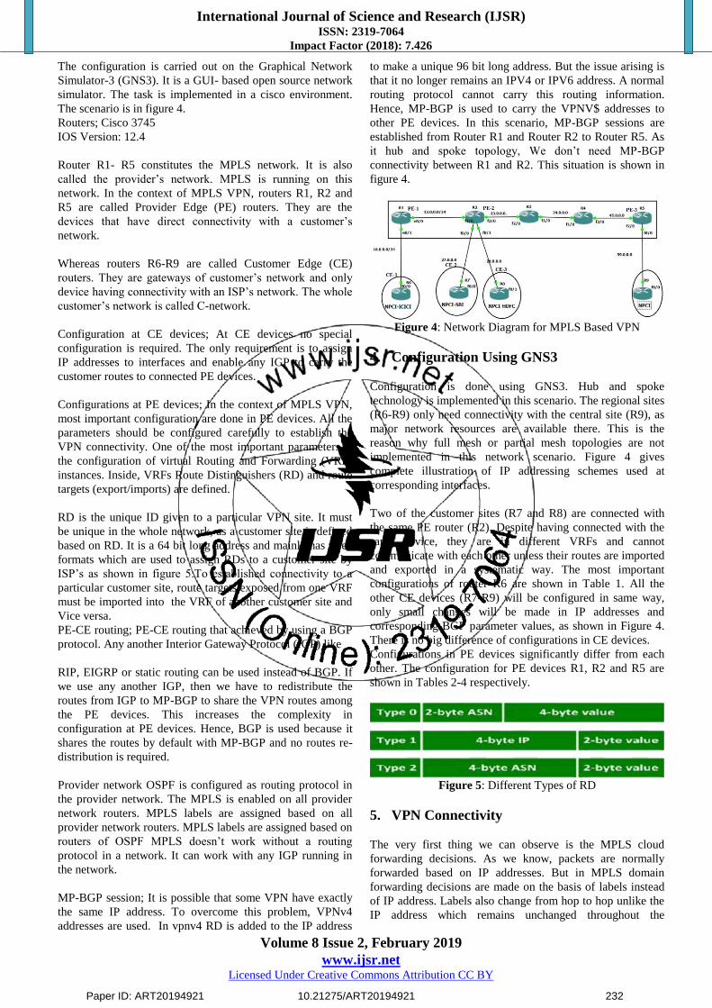
MP-BGP session; It is possible that some VPN have exactly
the same IP address. To overcome this problem, VPNv4
addresses are used. In vpnv4 RD is added to the IP address
to make a unique 96 bit long address. But the issue arising is
that it no longer remains an IPV4 or IPV6 address. A normal
routing protocol cannot carry this routing information.
Hence, MP-BGP is used to carry the VPNV$ addresses to
other PE devices. In this scenario, MP-BGP sessions are
established from Router R1 and Router R2 to Router R5. As
it hub and spoke topology, We don’t need MP-BGP
connectivity between R1 and R2. This situation is shown in
figure 4.
Figure 4: Network Diagram for MPLS Based VPN
4. Configuration Using GNS3
Configuration is done using GNS3. Hub and spoke
technology is implemented in this scenario. The regional sites
(R6-R9) only need connectivity with the central site (R9), as
major network resources are available there. This is the
reason why full mesh or partial mesh topologies are not
implemented in this network scenario. Figure 4 gives
complete illustration of IP addressing schemes used at
corresponding interfaces.
Two of the customer sites (R7 and R8) are connected with
the same PE router (R2). Despite having connected with the
same device, they are in different VRFs and cannot
communicate with each other unless their routes are imported
and exported in a systematic way. The most important
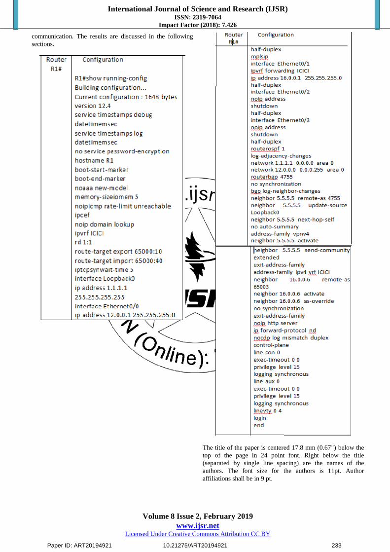
configurations of router R6 are shown in Table 1. All the
other CE devices (R7-R9) will be configured in same way,
only small changes will be made in IP addresses and
corresponding BGP parameter values, as shown in Figure 4.
There is no big difference of configurations in CE devices.
Configurations in PE devices significantly differ from each
other. The configuration for PE devices R1, R2 and R5 are
shown in Tables 2-4 respectively.
Figure 5: Different Types of RD
5. VPN Connectivity
The very first thing we can observe is the MPLS cloud
forwarding decisions. As we know, packets are normally
forwarded based on IP addresses. But in MPLS domain
forwarding decisions are made on the basis of labels instead
of IP address. Labels also change from hop to hop unlike the
IP address which remains unchanged throughout the
Paper ID: ART20194921 10.21275/ART20194921 232
International Journal of Science and Research (IJSR) ISSN: 2319-7064
Impact Factor (2018): 7.426
Volume 8 Issue 2, February 2019
www.ijsr.net Licensed Under Creative Commons Attribution CC BY
communication. The results are discussed in the following
sections.
The title of the paper is centered 17.8 mm (0.67") below the
top of the page in 24 point font. Right below the title
(separated by single line spacing) are the names of the
authors. The font size for the authors is 11pt. Author
affiliations shall be in 9 pt.
Paper ID: ART20194921 10.21275/ART20194921 233
International Journal of Science and Research (IJSR) ISSN: 2319-7064
Impact Factor (2018): 7.426
Volume 8 Issue 2, February 2019
www.ijsr.net Licensed Under Creative Commons Attribution CC BY
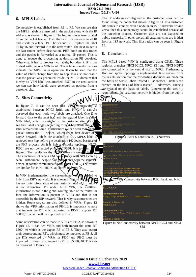
6. MPLS Labels
Connectivity is established from R1 to R5. We can see that
the MPLS labels are inserted in the packet along with the IP
address, as shown in figure 8. The Ingress router inserts label
18 in the packet header. Then the first LSR removes label 18
and inserts new label 19. The second LSR replace the label
19 by 16 and forward it to the next router. The next router is
the last router before destination. PHP done on this router
and the packet is forwarded as a normal IP packet. This is
done to reduce the processing at destination PE devoices.
Otherwise, it has to process two labels, but after PHP it has
to deal with just one VPN label. These label transformations
indicate that MPLS is in operation. It can be seen that the
value of labels change from hop to hop. It is also noticeable
that the packet was generated inside the MPLS domain: that
is why no VPN label was attached. BUT in the next section
we can see how labels were generated as packets from a
customer site.
7. Sites Connectivity
In figure 7, it can be seen that VPN connectivity is
established between ICICI bank and NPCI. It can be
observed that each node two labels are attached. One is to
forward data to the next hop and the second label is called
VPN label, which is assigned to the customer site. We can
see first label changes according to next hop while the VPN
label remains the same. Furthermore we can seen that when a
packet enters the PE device, which is the first device of a
MPLS network, labels are attached to it. A MPLS label is
removed one hop before the destination PE device because of
the PHP process. As it is hub and spoke topology, NPCI-
ICICI are not connected with NPCI-SBI. It is evident from
figure8. The results for the NPCI-SBI are shown in figure9.
The attachment of labels and connectivity with NPCI can be
seen. Furthermore, despite being connected with the same PE
device, it cannot communicate with NPCI-HDFC. The results
are similar for NPCI-HDFC as shown in figure10.
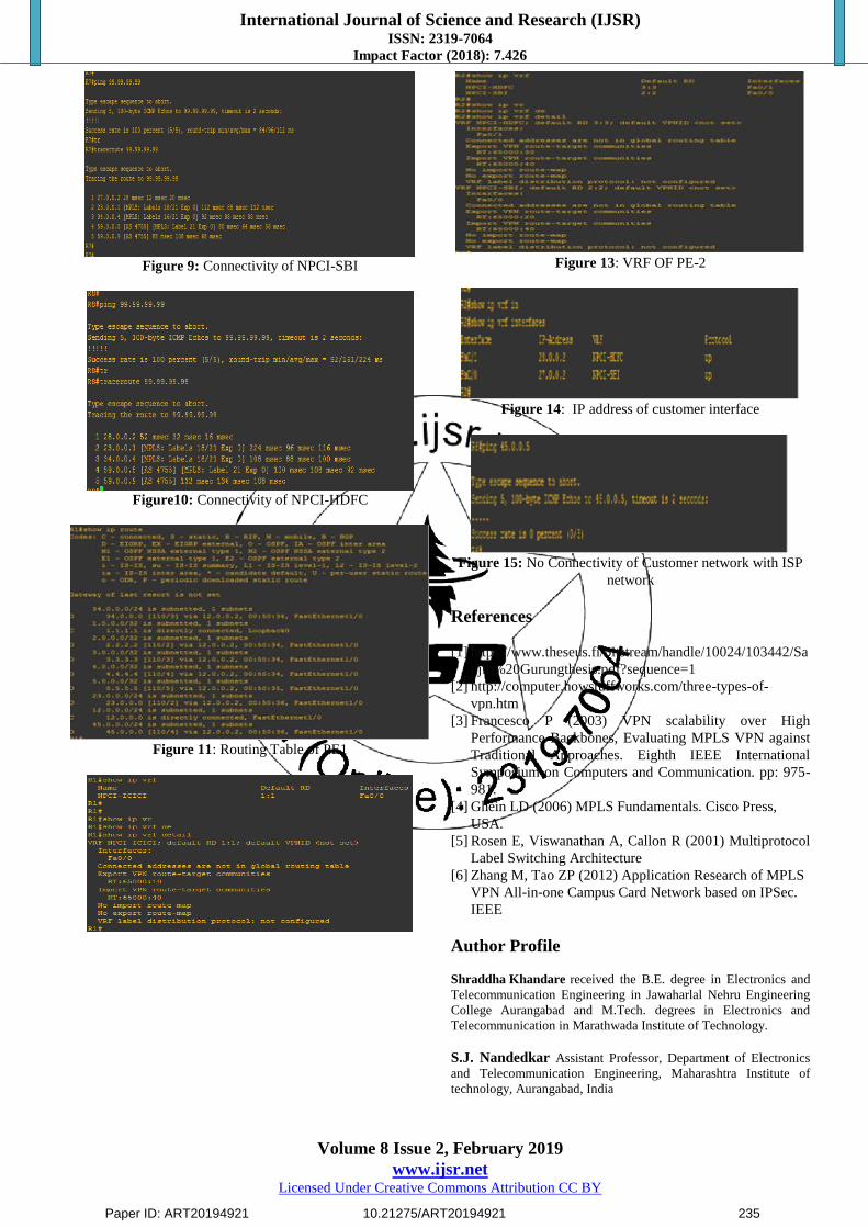
In VPN implementation the customer network is needed to
hide from ISP’s network. It is shown in Figure 11 that PE-1
has no route information of any customer sites. All it knows
is the destination PE node. In a VPN, the customer
information is not in the global routing table of the router. In
fact, the information is present in VRFs and that is not
accessible by the ISP network. That is why customer sites are
hidden. Route targets are also defined in VRFs. Figure 12
shows the VRF information of PE-1.It is important to note
that imports the RT which exported by PE-3.It exports RT
65000;10,which will be imported by PE-3.
Same observation can be made in VRFs of PE-2, as shown in
Figure 15. It has two VRFs and both import the same RT
6500; 40 which is the export RF of PE-3. They also export
their corresponding RTs, which must be imported at PE-3, all
the RTs exported by VRFs in PE-1 and PE-2 must be
imported. It should also export its RT of 65000; 40. This can
be observed in Figure 13.
The IP addresses configured at the customer sites can be
found using the connected shown in figure 14. If a customer
site wants to connect with a node in an ISP’S network or vice
versa, then this connectivity cannot be established because of
the tunneling process. Customer sites are not exposed to
public networks. In other words, all customer sites are hidden
from an ISP network. This illustration can be seen in Figure
15.
8. Conclusion
The MPLS based VPN is configured using GNS3. Three
regional branches NPCI-ICICI, NPCI-SBI and NPCI-HDFC
are connected with the central site of NPCI. Furthermore,
Hub and spoke topology is implemented. It is evident from
the results section that the forwarding decisions are made on
the basis of MPLS labels instead IP addresses. Tunnels are
created on the basis of labels instead IP addresses. Tunnels
are created on the basis of labels. Concerning the security
requirement, the customer network is hidden from the public
network.
Figure 6: MPLS Labels in ISP’s Network
Figure 7: VPN connectivity between ICICI bank and NPCI
Figure 8: No Connectivity between NPCI-ICICI and NPCI-
SBI
Paper ID: ART20194921 10.21275/ART20194921 234
International Journal of Science and Research (IJSR) ISSN: 2319-7064
Impact Factor (2018): 7.426
Volume 8 Issue 2, February 2019
www.ijsr.net Licensed Under Creative Commons Attribution CC BY
Figure 9: Connectivity of NPCI-SBI
Figure10: Connectivity of NPCI-HDFC
Figure 11: Routing Table of PE1
Figure 13: VRF OF PE-2
Figure 14: IP address of customer interface
Figure 15: No Connectivity of Customer network with ISP
network
References
[1] https://www.theseus.fi/bitstream/handle/10024/103442/Sa
njib%20Gurungthesis.pdf?sequence=1
[2] http://computer.howstuffworks.com/three-types-of-
vpn.htm
[3] Francesco P (2003) VPN scalability over High
Performance Backbones, Evaluating MPLS VPN against
Traditional Approaches. Eighth IEEE International
Symposium on Computers and Communication. pp: 975-
981.
[4] Ghein LD (2006) MPLS Fundamentals. Cisco Press,
USA.
[5] Rosen E, Viswanathan A, Callon R (2001) Multiprotocol
Label Switching Architecture
[6] Zhang M, Tao ZP (2012) Application Research of MPLS
VPN All-in-one Campus Card Network based on IPSec.
IEEE
Author Profile
Shraddha Khandare received the B.E. degree in Electronics and
Telecommunication Engineering in Jawaharlal Nehru Engineering
College Aurangabad and M.Tech. degrees in Electronics and
Telecommunication in Marathwada Institute of Technology.
S.J. Nandedkar Assistant Professor, Department of Electronics
and Telecommunication Engineering, Maharashtra Institute of
technology, Aurangabad, India
Paper ID: ART20194921 10.21275/ART20194921 235