Embed Size (px)
Citation preview
Volume 6 • Issue 5 • 1000193J Inform Tech Softw Eng, an open access journalISSN: 2165-7866
Ahmed et al., J Inform Tech Softw Eng 2016, 6:5DOI: 10.4172/2165-7866.1000193
Review Article Open Access
*Corresponding author: Farooq Ahmed, Department of Computer Science,University of Gujarat, Sialkot, Pakistan, Tel: +923346129370; E-mail: [email protected]
Received November 28, 2016; Accepted December 06, 2016; Published December 12, 2016
Citation: Ahmed F, Butt ZUA, Siddiqui UA (2016) MPLS based VPN Implementation in a Corporate Environment. J Inform Tech Softw Eng 6: 193. doi: 10.4172/2165-7866.1000193
Copyright: © 2016 Ahmed F, et al. This is an open-access article distributed under the terms of the Creative Commons Attribution License, which permits unrestricted use, distribution, and reproduction in any medium, provided the original author and source are credited.
Keywords: Multi-protocol label switching (MPLS); Virtual privatenetwork (VPN); Graphical network simulator-3 (GNS3); Internet service provider (ISP); Wide area network (WAN); Border gateway protocol (BGP)
Abbreviations: VPN: Virtual Private Network; MPLS: Multi-protocol Label Switching; ATM: Asynchronous Transfer Mode; FR: Frame Relay; IOS: Internetwork Operating System; IPSec: Internet Protocol Security Protocol; GNS3: Graphical Network Simulator-3; WAN: Wide Area Network; LAN: Local Area Network; ISP: Internet Service Provider; FEC: Forward Equivalency Class; LIB: Label Information Base; P-Network: Provider Network; C-Network: Customer Network; CE: Customer Edge; PE: Provider Edge; GUI: Graphical User Interface; BGP: Border Gateway Protocol; MP-BGP: Multi-protocol Border Gateway Protocol; OSPF: Open Shortest Path First; PPTP: Point-To-Point Tunneling Protocol; L2TP: Layer 2 Tunneling Protocol; SSL: Secure Socket Layer; VRF: Virtual Routing and Forwarding
Virtual Private NetworkToday the offices of organizations are widely spread across different
geographic locations. This far reaching is due to the increase in business activities and the eagerness to grasp more market share. As a result, more offices have to be established at different locations. In today’s globalized business world, new offices may be located inside a country or can be spread across different continents as well. Because of this technical environment, all the remote offices should have efficient network connectivity with their head office.
What is VPN?The problem arises that all the offices are far away from each other.
The organizations have to install a physical medium to establish this connectivity. As a result, they have to install their own lines or use leased lines. But this results in very high costs, technical and legal headache. Is there any way to solve this issue? The optimum solution is Virtual Private Network (VPN). A VPN is defined as a private data network that makes use of the public telecommunication infrastructure, maintaining privacy through the use of a tunneling protocol and security procedures [1]. Thus, VPN is used to counter this narrative. It makes a tunnel securely transmit private data over a public network. It hides the customer’s network from public access as well, despite using the public network infrastructure. It is a very important element when considering security aspects of a network.
Types of VPN
Due to its importance, VPN has become a popular solution deployed in many industrial environments. Many variations are possible while implementing a VPN. It can be categorized based on a tunneling protocol (layer 2 or layer 3), topology implemented (full mesh, hub and spoke) and infrastructure (site-to-site, remote VPN). VPN is mainly categorized as follows [2]:
• Site-to-Site VPN
• Remote (Web/SSL) VPN
Site-to-Site VPN: In site-to-site VPNs, customer sites are at a fixedgeographic location. VPN connectivity is established among sites. All sites are connected with an internet service provider (ISP) network. A tunneling protocol is enabled to create a virtual tunnel over the public network to securely transmit data.
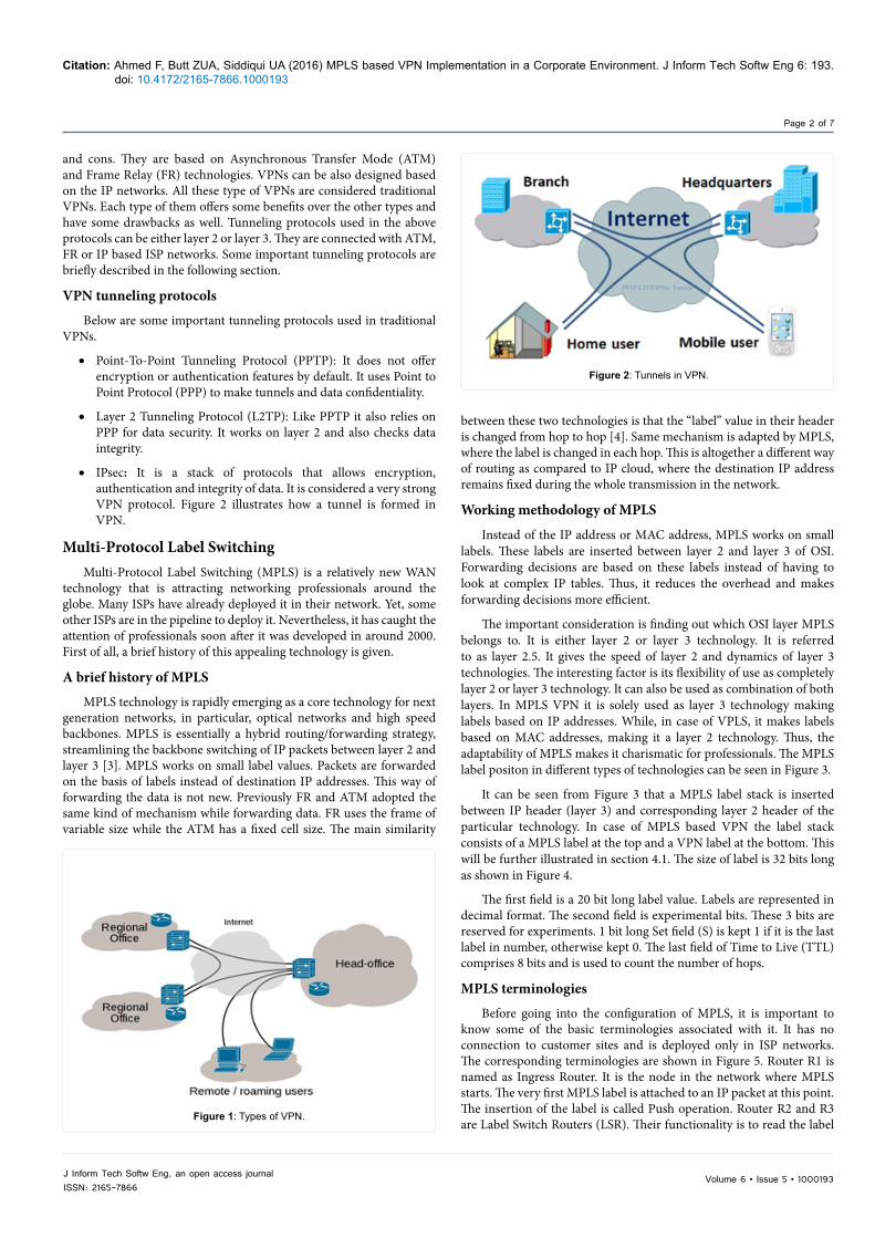
Remote (Web/SSL) VPN: In Remote VPNs, the customer is not fixed to a place, but roams around. All he/she needs is an Internet connectivity to get secure access to the organization`s central network. A client software is installed on a customer`s device, and the customer is assigned a unique username and password to get access. A virtual tunnel is also created to transmit data securely over an ISP`s network. Both types of VPN are shown in Figure 1. A Site-to-Site VPN is established from regional offices to head office. Roaming users have the access to head office through a Remote VPN.
Traditional VPN
There are different VPN technologies available with various pros
MPLS based VPN Implementation in a Corporate EnvironmentFarooq Ahmed1*, Zain Ul Abedin Butt2 and Uzair Ahmad Siddiqui3
1Department of Computer Science, University of Gujarat, Sialkot, Pakistan2Department of Electrical Engineering, CASE, Islamabad, Pakistan3Department of Computer Science, Virtual University, Lahore, Pakistan
AbstractToday organizations are spread across the globe due to higher business activities. The network connectivity
among the offices at different geographic locations has become a challenge for network professionals. VPN is used to counter this narrative. It has become a popular industry solution in recent years. MPLS is a relatively newer WAN technology providing advantages over other technologies. At the same time, it is compatible with existing technologies like ATM, FR, Ethernet and SONET. VPN having connectivity via MPLS infrastructure is known as MPLS VPN. It offers many advantages over traditional VPN solutions. In this project, MPLS based VPN is implemented in a corporate environment. Three regional offices of an organization are connected with the central site through MPLS based ISP’s network. Hub and spoke topology is implemented in this scenario. The connectivity among the sites is established and forwarding decisions are made on the bases of MPLS labels instead of IP addresses. Furthermore, it is also observable in results that MPLS doesn’t need any other tunneling protocol unlike traditional VPNs. It makes tunnels based on labels. Concerning the security requirements, it hides the customer’s network from ISP’s network, which is discussed in the results section.
Journal ofInformation Technology & Software Engineering
Journal of
Info
rmat
ion
Technology & Softw
are Engineering
ISSN: 2165-7866
Volume 6 • Issue 5 • 1000193J Inform Tech Softw Eng, an open access journalISSN: 2165-7866
Citation: Ahmed F, Butt ZUA, Siddiqui UA (2016) MPLS based VPN Implementation in a Corporate Environment. J Inform Tech Softw Eng 6: 193. doi: 10.4172/2165-7866.1000193
Page 2 of 7
between these two technologies is that the “label” value in their header is changed from hop to hop [4]. Same mechanism is adapted by MPLS, where the label is changed in each hop. This is altogether a different way of routing as compared to IP cloud, where the destination IP address remains fixed during the whole transmission in the network.
Working methodology of MPLS
Instead of the IP address or MAC address, MPLS works on small labels. These labels are inserted between layer 2 and layer 3 of OSI. Forwarding decisions are based on these labels instead of having to look at complex IP tables. Thus, it reduces the overhead and makes forwarding decisions more efficient.
The important consideration is finding out which OSI layer MPLS belongs to. It is either layer 2 or layer 3 technology. It is referred to as layer 2.5. It gives the speed of layer 2 and dynamics of layer 3 technologies. The interesting factor is its flexibility of use as completely layer 2 or layer 3 technology. It can also be used as combination of both layers. In MPLS VPN it is solely used as layer 3 technology making labels based on IP addresses. While, in case of VPLS, it makes labels based on MAC addresses, making it a layer 2 technology. Thus, the adaptability of MPLS makes it charismatic for professionals. The MPLS label positon in different types of technologies can be seen in Figure 3.
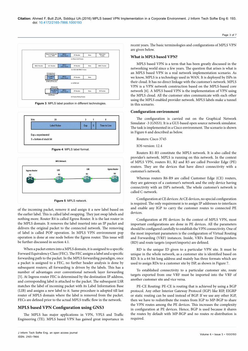
It can be seen from Figure 3 that a MPLS label stack is inserted between IP header (layer 3) and corresponding layer 2 header of the particular technology. In case of MPLS based VPN the label stack consists of a MPLS label at the top and a VPN label at the bottom. This will be further illustrated in section 4.1. The size of label is 32 bits long as shown in Figure 4.
The first field is a 20 bit long label value. Labels are represented in decimal format. The second field is experimental bits. These 3 bits are reserved for experiments. 1 bit long Set field (S) is kept 1 if it is the last label in number, otherwise kept 0. The last field of Time to Live (TTL) comprises 8 bits and is used to count the number of hops.
MPLS terminologies
Before going into the configuration of MPLS, it is important to know some of the basic terminologies associated with it. It has no connection to customer sites and is deployed only in ISP networks. The corresponding terminologies are shown in Figure 5. Router R1 is named as Ingress Router. It is the node in the network where MPLS starts. The very first MPLS label is attached to an IP packet at this point. The insertion of the label is called Push operation. Router R2 and R3 are Label Switch Routers (LSR). Their functionality is to read the label
and cons. They are based on Asynchronous Transfer Mode (ATM) and Frame Relay (FR) technologies. VPNs can be also designed based on the IP networks. All these type of VPNs are considered traditional VPNs. Each type of them offers some benefits over the other types and have some drawbacks as well. Tunneling protocols used in the above protocols can be either layer 2 or layer 3. They are connected with ATM, FR or IP based ISP networks. Some important tunneling protocols are briefly described in the following section.
VPN tunneling protocols
Below are some important tunneling protocols used in traditional VPNs.
• Point-To-Point Tunneling Protocol (PPTP): It does not offer encryption or authentication features by default. It uses Point to Point Protocol (PPP) to make tunnels and data confidentiality.
• Layer 2 Tunneling Protocol (L2TP): Like PPTP it also relies on PPP for data security. It works on layer 2 and also checks data integrity.
• IPsec: It is a stack of protocols that allows encryption, authentication and integrity of data. It is considered a very strong VPN protocol. Figure 2 illustrates how a tunnel is formed in VPN.
Multi-Protocol Label SwitchingMulti-Protocol Label Switching (MPLS) is a relatively new WAN
technology that is attracting networking professionals around the globe. Many ISPs have already deployed it in their network. Yet, some other ISPs are in the pipeline to deploy it. Nevertheless, it has caught the attention of professionals soon after it was developed in around 2000. First of all, a brief history of this appealing technology is given.
A brief history of MPLS
MPLS technology is rapidly emerging as a core technology for next generation networks, in particular, optical networks and high speed backbones. MPLS is essentially a hybrid routing/forwarding strategy, streamlining the backbone switching of IP packets between layer 2 and layer 3 [3]. MPLS works on small label values. Packets are forwarded on the basis of labels instead of destination IP addresses. This way of forwarding the data is not new. Previously FR and ATM adopted the same kind of mechanism while forwarding data. FR uses the frame of variable size while the ATM has a fixed cell size. The main similarity
Figure 1: Types of VPN.
Figure 2: Tunnels in VPN.
Volume 6 • Issue 5 • 1000193J Inform Tech Softw Eng, an open access journalISSN: 2165-7866
Citation: Ahmed F, Butt ZUA, Siddiqui UA (2016) MPLS based VPN Implementation in a Corporate Environment. J Inform Tech Softw Eng 6: 193. doi: 10.4172/2165-7866.1000193
Page 3 of 7
Figure 3: MPLS label position in different technologies.
Figure 4: MPLS label format.
Figure 5: MPLS network.
of the incoming packet, remove it and assign it a new label based on the earlier label. This is called label swapping. They just swap labels and nothing more. Router R4 is called Egress Router. It is the last router in the MPLS domain. It removes the label inserted into an IP packet and delivers the original packet to the connected network. The removing of label is called POP operation. In MPLS VPN environment pop operation is done at one node before the Egress router. This issue will be further discussed in section 4.1.
When a packet enters into a MPLS domain, it is assigned to a specific Forward Equivalency Class (FEC). The FEC assigns a label and a specific forwarding path to the packet. In the MPLS forwarding paradigm, once a packet is assigned to a FEC, no further header analysis is done by subsequent routers; all forwarding is driven by the labels. This has a number of advantages over conventional network layer forwarding [5]. At Ingress router FEC is determined by the destination IP address, and corresponding label is attached to the packet. The subsequent LSR matches the label of incoming packet with its Label Information Base (LIB) and assigns a new label to it. Same procedure is adopted till last router of MPLS domain where the label is removed from the packet. FECs are defined prior to the actual MPLS traffic flow in the network.
MPLS based VPN Configuration using GNS3The MPLS has major applications in VPN, VPLS and Traffic
Engineering (TE). MPLS based VPN has gained great importance in
recent years. The basic terminologies and configurations of MPLS VPN are given below.
What is MPLS based VPN?
MPLS based VPN is a term that has been greatly discussed in the networking world since a few years. The question that arises is what is an MPLS based VPN in a real network implementation scenario. As we know, MPLS is a technology used in WAN. It is deployed by ISPs in their cloud. It has no direct linkage with the customer’s network. MPLS VPN is a VPN network construction based on the MPLS-based core network [6]. A MPLS based VPN is the implementation of VPN using the MPLS cloud. All the customer sites communicate with each other using the MPLS enabled provider network. MPLS labels make a tunnel in this scenario.
Configuration environment
The configuration is carried out on the Graphical Network Simulator -3 (GNS3). It is a GUI-based open source network simulator. The task is implemented in a Cisco environment. The scenario is shown in Figure 6 and described as below.
Routers: Cisco 3745
IOS version: 12.4
Routers R1-R5 constitute the MPLS network. It is also called the provider’s network. MPLS is running on this network. In the context of MPLS VPN, routers R1, R2 and R5 are called Provider Edge (PE) routers. They are the devices that have direct connectivity with a customer’s network.
Whereas routers R6-R9 are called Customer Edge (CE) routers, they are gateways of a customer’s network and the only device having connectivity with an ISP’s network. The whole customer’s network is called C-network.
Configuration at CE devices: At CE devices, no special configuration is required. The only requirement is to assign IP addresses to interfaces and enable any IGP to carry the customer routes to connected PE devices.
Configuration at PE devices: In the context of MPLS VPN, most important configurations are done in PE devices. All the parameters should be configured carefully to establish the VPN connectivity. One of the most important parameters is the configuration of Virtual Routing and Forwarding (VRF) instances. Inside, VRFs Route Distinguishers (RD) and route targets (export/imports) are defined.
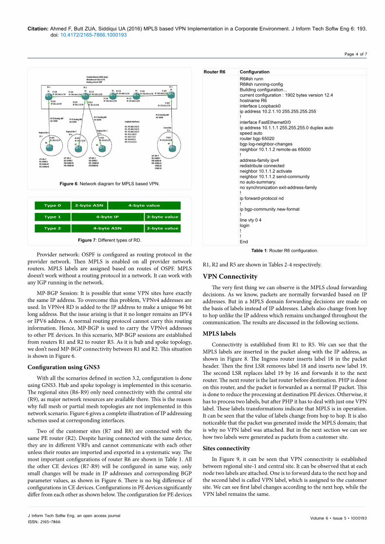
RD is the unique ID given to a particular VPN site. It must be unique in the whole network, as a customer site is identified based on RD. It is a 64 bit long address and mainly has three formats which are used to assign RDs to a customer site by ISP, as shown in Figure 7.
To established connectivity to a particular customer site, route targets exported from one VRF must be imported into the VRF of another customer site and vice versa.
PE-CE Routing: PE-CE is routing that is achieved by using a BGP protocol. Any other Interior Gateway Protocol (IGP) like RIP, EIGRP or static routing can be used instead of BGP. If we use any other IGP, then we have to redistribute the routes from IGP to MP-BGP to share the VPN routes among the PE devices. This increases the complexity in configuration at PE devices. Hence, BGP is used because it shares the routes by default with MP-BGP and no routes re-distribution is required.
Volume 6 • Issue 5 • 1000193J Inform Tech Softw Eng, an open access journalISSN: 2165-7866
Citation: Ahmed F, Butt ZUA, Siddiqui UA (2016) MPLS based VPN Implementation in a Corporate Environment. J Inform Tech Softw Eng 6: 193. doi: 10.4172/2165-7866.1000193
Page 4 of 7
Figure 6: Network diagram for MPLS based VPN.
Figure 7: Different types of RD.
Provider network: OSPF is configured as routing protocol in the provider network. Then MPLS is enabled on all provider network routers. MPLS labels are assigned based on routes of OSPF. MPLS doesn’t work without a routing protocol in a network. It can work with any IGP running in the network.
MP-BGP Session: It is possible that some VPN sites have exactly the same IP address. To overcome this problem, VPNv4 addresses are used. In VPNv4 RD is added to the IP address to make a unique 96 bit long address. But the issue arising is that it no longer remains an IPV4 or IPV6 address. A normal routing protocol cannot carry this routing information. Hence, MP-BGP is used to carry the VPNv4 addresses to other PE devices. In this scenario, MP-BGP sessions are established from routers R1 and R2 to router R5. As it is hub and spoke topology, we don’t need MP-BGP connectivity between R1 and R2. This situation is shown in Figure 6.
Configuration using GNS3
With all the scenarios defined in section 3.2, configuration is done using GNS3. Hub and spoke topology is implemented in this scenario. The regional sites (R6-R9) only need connectivity with the central site (R9), as major network resources are available there. This is the reason why full mesh or partial mesh topologies are not implemented in this network scenario. Figure 6 gives a complete illustration of IP addressing schemes used at corresponding interfaces.
Two of the customer sites (R7 and R8) are connected with the same PE router (R2). Despite having connected with the same device, they are in different VRFs and cannot communicate with each other unless their routes are imported and exported in a systematic way. The most important configurations of router R6 are shown in Table 1. All the other CE devices (R7-R9) will be configured in same way, only small changes will be made in IP addresses and corresponding BGP parameter values, as shown in Figure 6. There is no big difference of configurations in CE devices. Configurations in PE devices significantly differ from each other as shown below. The configuration for PE devices
Router R6 ConfigurationR6#sh runnR6#sh running-configBuilding configuration...current configuration : 1902 bytes version 12.4hostname R6interface Loopback0ip address 10.2.1.10 255.255.255.255!interface FastEthernet0/0ip address 10.1.1.1 255.255.255.0 duplex autospeed autorouter bgp 65020bgp log-neighbor-changesneighbor 10.1.1.2 remote-as 65000!address-family ipv4 redistribute connected neighbor 10.1.1.2 activateneighbor 10.1.1.2 send-communityno auto-summary. no synchronization exit-address-family!ip forward-protocol nd!ip bgp-community new-format!line vty 0 4login!!End
Table 1: Router R6 configuration.
R1, R2 and R5 are shown in Tables 2-4 respectively.
VPN ConnectivityThe very first thing we can observe is the MPLS cloud forwarding
decisions. As we know, packets are normally forwarded based on IP addresses. But in a MPLS domain forwarding decisions are made on the basis of labels instead of IP addresses. Labels also change from hop to hop unlike the IP address which remains unchanged throughout the communication. The results are discussed in the following sections.
MPLS labels
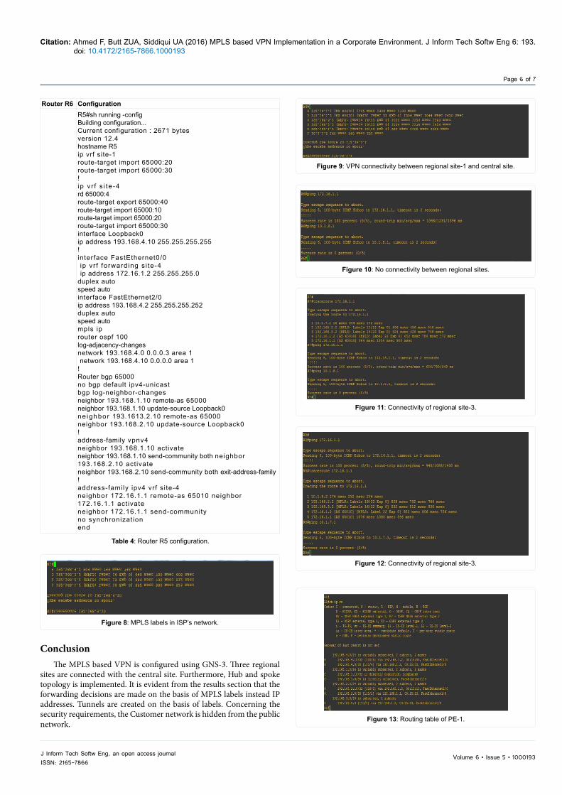
Connectivity is established from R1 to R5. We can see that the MPLS labels are inserted in the packet along with the IP address, as shown in Figure 8. The Ingress router inserts label 18 in the packet header. Then the first LSR removes label 18 and inserts new label 19. The second LSR replaces label 19 by 16 and forwards it to the next router. The next router is the last router before destination. PHP is done on this router, and the packet is forwarded as a normal IP packet. This is done to reduce the processing at destination PE devices. Otherwise, it has to process two labels, but after PHP it has to deal with just one VPN label. These labels transformations indicate that MPLS is in operation. It can be seen that the value of labels change from hop to hop. It is also noticeable that the packet was generated inside the MPLS domain; that is why no VPN label was attached. But in the next section we can see how two labels were generated as packets from a customer site.
Sites connectivity
In Figure 9, it can be seen that VPN connectivity is established between regional site-1 and central site. It can be observed that at each node two labels are attached. One is to forward data to the next hop and the second label is called VPN label, which is assigned to the customer site. We can see first label changes according to the next hop, while the VPN label remains the same.

Volume 6 • Issue 5 • 1000193J Inform Tech Softw Eng, an open access journalISSN: 2165-7866
Citation: Ahmed F, Butt ZUA, Siddiqui UA (2016) MPLS based VPN Implementation in a Corporate Environment. J Inform Tech Softw Eng 6: 193. doi: 10.4172/2165-7866.1000193
Page 5 of 7
Router R6 Configuration
R1#sh running-configBuilding configuration...current configuration : 2422 bytes! version 12.4hostname R1ip vrf site-1rd 65000:1route-target export 65000:1 route-target export 65000:10 route-target import 65000:4 route-target import 65000:40!interface Loopback0ip address 193.168.1.10 255.255.255.255!interface fastethernet0/0ip vrf forwarding site-1ip address 10.1.1.2 255.255.255.0 duplex autospeed autointerface fastethernet1/0ip address 193.168.1.1 255.255.255.252 duplex autospeed autompls iprouter ospf 100log-adjacency-changesnetwork 193.168.1.0 0.0.0.3 area 1 network 193.168.1.10 0.0.0.0 area 1!router bgp 65000no bgp default ipv4-unicastbgp log-neighbor-changesneighbor 193.168.4.10 remote-as 65000 neighbor 193.168.4.10 update-source Loopback0!address-family vpnv4neighbor 193.168.4.10 activateneighbor 193.168.4.10 send-community both exit-address-family!address-family ipv4 vrf site-1neighbor 10.1.1.1 remote-as 65020neighbor 10.1.1.1 activateneighbor 10.1.1.1 send-communityno synchronization exit-address-familyend
Table 2: Router R1 configuration.
Router R6 ConfigurationR2#sh running-config building configuration...!v e r s i o n 1 2 . 4 h o s t n a m e R 2 ip cefi p v r f s i t e -2rd 65000:2r o u t e - t a r g e t e x p o r t 6 5 0 0 0 : 2 0 r o u t e - t a r g e t i m p o r t 6 5 0 0 0 : 4 0!i p v r f s i t e -3rd 65000:3r o u t e - t a r g e t e x p o r t 6 5 0 0 0 : 3 0 r o u t e - t a r g e t i m p o r t 6 5 0 0 0 : 4 0i n t e r f a c e L o o p b a c k 0i p a d d r e s s 1 9 3 . 1 6 8 . 2 . 1 0 2 5 5 . 2 5 5 . 2 5 5 . 2 5 5!i n t e r f a c e F a s t E t h e r n e t 0 / 0i p v r f f o r w a r d i n g s i t e - 2i p a d d r e s s 1 0 . 1 . 7 . 2 2 5 5 . 2 5 5 . 2 5 5 . 0i n t e r f a c e F a s t E t h e r n e t 0 / 1i p v r f f o r w a r d i n g s i t e - 3i p a d d r e s s 1 0 . 1 . 8 . 2 2 5 5 . 2 5 5 . 2 5 5 . 0i n t e r f a c e F a s t E t h e r n e t 1 / 0i p a d d r e s s 1 9 3 . 1 6 8 . 1 . 2 2 5 5 . 2 5 5 . 2 5 5 . 2 5 2m p l s i p!i n t e r f a c e F a s t E t h e r n e t 2 / 0i p a d d r e s s 1 9 3 . 1 6 8 . 2 . 1 2 5 5 . 2 5 5 . 2 5 5 . 2 5 2m p l s i pr o u t e r o s p f 1 0 0l o g - a d j a c e n c y - c h a n g e sn e t w o r k 1 9 3 . 1 6 8 . 1 . 0 0 . 0 . 0 . 3 a r e a 1 n e t w o r k 1 9 3 . 1 6 8 . 2 . 0 0 . 0 . 0 . 3 a r e a 1 n e t w o r k 1 9 3 . 1 6 8 . 2 . 1 0 0 . 0 . 0 . 0 a r e a 1!n o b g p d e f a u l t i p v 4 - u n i c a s tb g p l o g - n e i g h b o r - c h a n g e sn e i g h b o r 1 9 3 . 1 6 8 . 4 . 1 0 r e m o t e - a s 6 5 0 0 0n e i g h b o r 1 9 3 . 1 6 8 . 4 . 1 0 u p d a t e - s o u r c e L o o p b a c k 0!address- fami ly vpnv4n e i g h b o r 1 9 3 . 1 6 8 . 4 . 1 0 a c t i v a t en e i g h b o r 1 9 3 . 1 6 8 . 4 . 1 0 s e n d - c o m m u n i t y b o t h e x i t - a d d r e s s - f a m i l y!a d d r e s s - f a m i l y i p v 4 v r f s i t e - 3n e i g h b o r 1 0 . 1 . 8 . 1 r e m o t e - a s 6 5 0 4 0n e i g h b o r 1 0 . 1 . 8 . 1 a c t i v a t en e i g h b o r 1 0 . 1 . 8 . 1 s e n d - c o m m u n i t yn o s y n c h r o n i z a t i o n e x i t - a d d r e s s - f a m i l y!a d d r e s s - f a m i l y i p v 4 v r f s i t e - 2n e i g h b o r 1 0 . 1 . 7 . 1 r e m o t e - a s 6 5 0 3 0n e i g h b o r 1 0 . 1 . 7 . 1 a c t i v a t en e i g h b o r 1 0 . 1 . 7 . 1 s e n d - c o m m u n i t ye n d
Table 3: Router R2 configuration.
Furthermore, we can see that when a packet enters the PE device, which is the first device of a MPLS network, labels are attached to it. A MPLS label is removed one hop before the destination PE device because of the PHP process. As it is hub and spoke topology, regional sites are not connected with each other. It is evident from Figure 10. The results for the regional site-2 are shown in Figure 11. The attachment of labels and connectivity with a central site can be seen. Furthermore, despite being connected with the same PE device, it cannot communicate with a regional site-3. The results are similar for regional site-3 as shown in Figure 12.
In a VPN implementation the customer network is needed to hide from ISP’s network. It is shown in Figure 13 that PE-1 has no route information of any customer sites. All it knows is the destination PE node.
In a VPN, the customer information is not in the global routing table of the router. In fact, the information is present in VRFs and that is not accessible by the ISP network. That is why customer sites are hidden. Route targets are also defined in VRFs. Figure 14 shows the VRF information of PE-1. It is important to note that imports the RT which is exported by PE-3. It exports RT 65000:10, which will be imported by PE-3.
Same observations can be made in VRFs of PE-2, as shown in Figure 15. It has two VRFs and both import the same RT 65000:40, which is the export RF of PE-3. They also export their corresponding RTs, which must be imported at PE-3. At PE-3, all the RTs exported by VRFs in PE-1 and PE-2 must be imported. It should also export its RT of 65000:40. This can be observed in Figure 16.
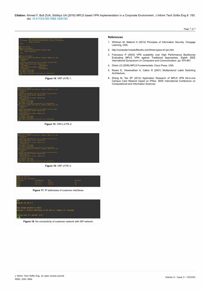
The IP addresses configured at the customer sites can be found using the command shown in Figure 17. If a customer site wants to connect with a node in an ISP’s network or vice versa, then this connectivity cannot be established because of the tunneling process. Customer sites are not exposed to public networks. In other words, all customer sites are hidden from an ISP network. This illustration can be seen in Figure 18.
Volume 6 • Issue 5 • 1000193J Inform Tech Softw Eng, an open access journalISSN: 2165-7866
Citation: Ahmed F, Butt ZUA, Siddiqui UA (2016) MPLS based VPN Implementation in a Corporate Environment. J Inform Tech Softw Eng 6: 193. doi: 10.4172/2165-7866.1000193
Page 6 of 7
Figure 8: MPLS labels in ISP’s network.
Router R6 ConfigurationR5#sh running -config Building configuration...Current configuration : 2671 bytes version 12.4hostname R5ip vrf site-1route-target import 65000:20 route-target import 65000:30!ip v r f s i te -4rd 65000:4route-target export 65000:40 route-target import 65000:10 route-target import 65000:20 route-target import 65000:30interface Loopback0ip address 193.168.4.10 255.255.255.255!interface FastEthernet0/0 ip vr f forwarding s i te-4 ip address 172.16.1.2 255.255.255.0duplex autospeed autointerface FastEthernet2/0ip address 193.168.4.2 255.255.255.252 duplex autospeed autompls iprouter ospf 100log-adjacency-changesnetwork 193.168.4.0 0.0.0.3 area 1 network 193.168.4.10 0.0.0.0 area 1!Router bgp 65000no bgp default ipv4-unicastbgp log-neighbor-changesneighbor 193.168.1.10 remote-as 65000neighbor 193.168.1.10 update-source Loopback0ne ighbor 193.1613.2.10 remote-as 65000neighbor 193.168.2.10 update-source Loopback0!address-family vpnv4neighbor 193.168.1.10 activateneighbor 193.168.1.10 send-community both neighbor 193.168.2.10 activateneighbor 193.168.2.10 send-community both exit-address-family!address-family ipv4 vrf si te-4neighbor 172.16.1.1 remote-as 65010 neighbor 172.16.1.1 activateneighbor 172.16.1.1 send-community no synchronizationend
Table 4: Router R5 configuration.
Figure 9: VPN connectivity between regional site-1 and central site.
ConclusionThe MPLS based VPN is configured using GNS-3. Three regional
sites are connected with the central site. Furthermore, Hub and spoke topology is implemented. It is evident from the results section that the forwarding decisions are made on the basis of MPLS labels instead IP addresses. Tunnels are created on the basis of labels. Concerning the security requirements, the Customer network is hidden from the public network.
Figure 10: No connectivity between regional sites.
Figure 11: Connectivity of regional site-3.
Figure 12: Connectivity of regional site-3.
Figure 13: Routing table of PE-1.
Volume 6 • Issue 5 • 1000193J Inform Tech Softw Eng, an open access journalISSN: 2165-7866
Citation: Ahmed F, Butt ZUA, Siddiqui UA (2016) MPLS based VPN Implementation in a Corporate Environment. J Inform Tech Softw Eng 6: 193. doi: 10.4172/2165-7866.1000193
Page 7 of 7
Figure 14: VRF of PE-1.
Figure 15: VRFs of PE-2.
Figure 16: VRF of PE-3.
Figure 17: IP addresses of customer interfaces.
Figure 18: No connectivity of customer network with ISP network.
References
1. Whitman M, Mattord H (2012) Principles of Information Security. CengageLearning, USA.
2. http://computer.howstuffworks.com/three-types-of-vpn.htm
3. Francesco P (2003) VPN scalability over High Performance BackbonesEvaluating MPLS VPN against Traditional Approaches. Eighth IEEEInternational Symposium on Computers and Communication. pp: 975-981.
4. Ghein LD (2006) MPLS Fundamentals. Cisco Press, USA.
5. Rosen E, Viswanathan A, Callon R (2001) Multiprotocol Label SwitchingArchitecture.
6. Zhang M, Tao ZP (2012) Application Research of MPLS VPN All-in-oneCampus Card Network based on IPSec. IEEE International Conference onComputational and Information Sciences.