Embed Size (px)
DESCRIPTION
fe
Citation preview
Page 1
IEEE Power Engineering Society General MeetingIEEE Power Engineering Society General MeetingToronto, July 13Toronto, July 13--17, 200317, 2003
Panel SessionPanel Session
Practical Aspects of Practical Aspects of FerroresonanceFerroresonance
bybyIEEE T&D General Systems SubcommitteeIEEE T&D General Systems SubcommitteePractical Aspects of Practical Aspects of Ferroresonance Ferroresonance WGWG
Chairman: Bruce Mork, Michigan Tech UniversityChairman: Bruce Mork, Michigan Tech University
http://www.http://www.eeee..mtumtu..eduedu/faculty//faculty/bamorkbamork/FR_WG//FR_WG/
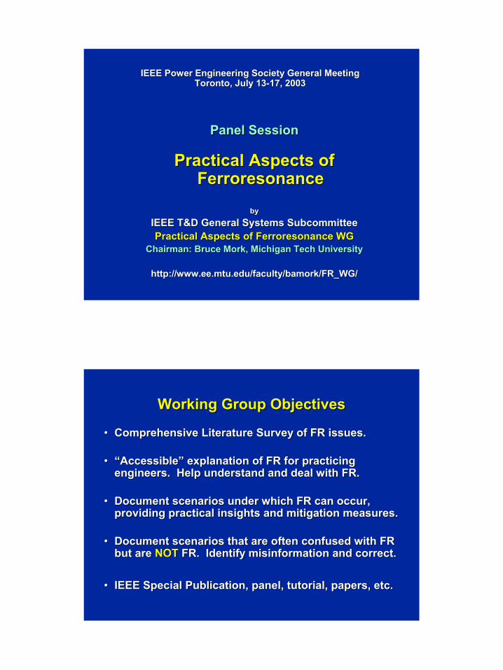
Working Group ObjectivesWorking Group Objectives
•• Comprehensive Literature Survey of FR issues.Comprehensive Literature Survey of FR issues.
•• “Accessible” explanation of FR for practicing “Accessible” explanation of FR for practicing engineers. Help understand and deal with FR.engineers. Help understand and deal with FR.
•• Document scenarios under which FR can occur, Document scenarios under which FR can occur, providing practical insights and mitigation measures.providing practical insights and mitigation measures.
•• Document scenarios that are often confused with FR Document scenarios that are often confused with FR but are but are NOTNOT FR. Identify misinformation and correct.FR. Identify misinformation and correct.
•• IEEE Special Publication, panel, tutorial, papers, etc. IEEE Special Publication, panel, tutorial, papers, etc.
Page 2
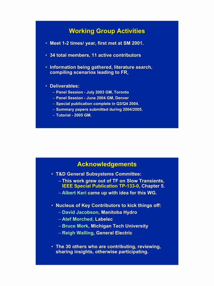
Working Group ActivitiesWorking Group Activities
•• Meet 1Meet 1--2 times/ year, first met at SM 2001.2 times/ year, first met at SM 2001.
•• 34 total members, 11 active contributors34 total members, 11 active contributors
•• Information being gathered, literature search, Information being gathered, literature search, compiling scenarios leading to FR, compiling scenarios leading to FR,
•• Deliverables:Deliverables:–– Panel Session Panel Session -- July 2003 GM, TorontoJuly 2003 GM, Toronto–– Panel Session Panel Session -- June 2004 GM, DenverJune 2004 GM, Denver–– Special publication complete in Q3/Q4 2004.Special publication complete in Q3/Q4 2004.–– Summary papers submitted during 2004/2005.Summary papers submitted during 2004/2005.–– Tutorial Tutorial -- 2005 GM.2005 GM.
AcknowledgementsAcknowledgements•• T&D General Subsystems Committee:T&D General Subsystems Committee:
–– This work grew out of TF on Slow Transients, This work grew out of TF on Slow Transients, IEEE Special Publication TPIEEE Special Publication TP--133133--00, Chapter 5., Chapter 5.
–– Albert Keri Albert Keri came up with idea for this WG.came up with idea for this WG.
•• Nucleus of Key Contributors to kick things off:Nucleus of Key Contributors to kick things off:–– David Jacobson,David Jacobson, Manitoba HydroManitoba Hydro–– Atef MorchedAtef Morched, , LabelecLabelec–– Bruce MorkBruce Mork, Michigan Tech University, Michigan Tech University–– ReighReigh WallingWalling, General Electric, General Electric
•• The 30 others who are contributing, reviewing, The 30 others who are contributing, reviewing, sharing insights, otherwise participating.sharing insights, otherwise participating.
Page 3
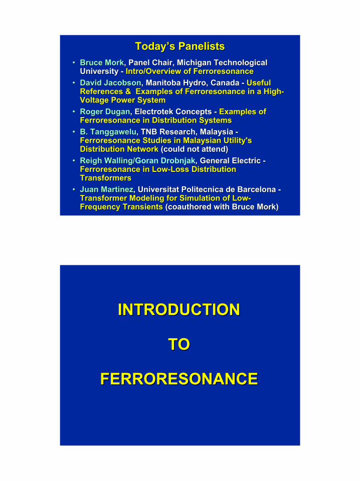
Today’s PanelistsToday’s Panelists•• Bruce MorkBruce Mork, Panel Chair, Michigan Technological , Panel Chair, Michigan Technological
University University -- Intro/Overview ofIntro/Overview of FerroresonanceFerroresonance•• David JacobsonDavid Jacobson, Manitoba Hydro, Canada , Manitoba Hydro, Canada -- Useful Useful
References & Examples ofReferences & Examples of FerroresonanceFerroresonance in a Highin a High--Voltage Power System Voltage Power System
•• Roger Roger DuganDugan,, ElectrotekElectrotek Concepts Concepts -- Examples ofExamples ofFerroresonanceFerroresonance in Distribution Systemsin Distribution Systems
•• B.B. TanggaweluTanggawelu, TNB Research, Malaysia , TNB Research, Malaysia --FerroresonanceFerroresonance Studies in Malaysian Utility's Studies in Malaysian Utility's Distribution NetworkDistribution Network (could not attend)(could not attend)
•• ReighReigh Walling/Walling/Goran Drobnjak, General Electric , General Electric --FerroresonanceFerroresonance in Lowin Low--Loss Distribution Loss Distribution TransformersTransformers
•• Juan MartinezJuan Martinez, , Universitat PolitecnicaUniversitat Politecnica de Barcelona de Barcelona --Transformer Modeling for Simulation of LowTransformer Modeling for Simulation of Low--Frequency TransientsFrequency Transients ((coauthored coauthored with Bruce Mork)with Bruce Mork)
INTRODUCTIONINTRODUCTION
TOTO
FERRORESONANCEFERRORESONANCE
Page 4
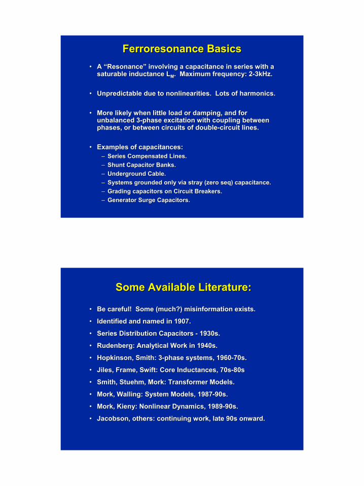
FerroresonanceFerroresonance BasicsBasics•• A “Resonance” involving a capacitance in series with a A “Resonance” involving a capacitance in series with a
saturable inductance Lsaturable inductance LMM. Maximum frequency: 2. Maximum frequency: 2--3kHz.3kHz.
•• Unpredictable due to nonlinearities. Lots of harmonics.Unpredictable due to nonlinearities. Lots of harmonics.
•• More likely when little load or damping, and for More likely when little load or damping, and for unbalanced 3unbalanced 3--phase excitation with coupling between phase excitation with coupling between phases, or between circuits of doublephases, or between circuits of double--circuit lines. circuit lines.
•• Examples of capacitances:Examples of capacitances:–– Series Compensated Lines.Series Compensated Lines.–– Shunt Capacitor Banks.Shunt Capacitor Banks.–– Underground Cable.Underground Cable.–– Systems grounded only via stray (zero Systems grounded only via stray (zero seqseq) capacitance.) capacitance.–– Grading capacitors on Circuit Breakers.Grading capacitors on Circuit Breakers.–– Generator Surge Capacitors.Generator Surge Capacitors.
Some Available Literature:Some Available Literature:
•• Be careful! Some (much?) misinformation exists.Be careful! Some (much?) misinformation exists.
•• Identified and named in 1907.Identified and named in 1907.
•• Series Distribution Capacitors Series Distribution Capacitors -- 1930s.1930s.
•• Rudenberg: Analytical Work in 1940s.Rudenberg: Analytical Work in 1940s.
•• Hopkinson, Smith: 3Hopkinson, Smith: 3--phase systems, 1960phase systems, 1960--70s.70s.
•• Jiles, Frame, Swift: Core Jiles, Frame, Swift: Core InductancesInductances, 70s, 70s--80s80s
•• Smith, Stuehm, Mork: Transformer Models.Smith, Stuehm, Mork: Transformer Models.
•• Mork, Walling: System Models, 1987Mork, Walling: System Models, 1987--90s.90s.
•• Mork, Kieny: Nonlinear Dynamics, 1989Mork, Kieny: Nonlinear Dynamics, 1989--90s.90s.
•• Jacobson, others: continuing work, late 90s onward.Jacobson, others: continuing work, late 90s onward.
Page 5
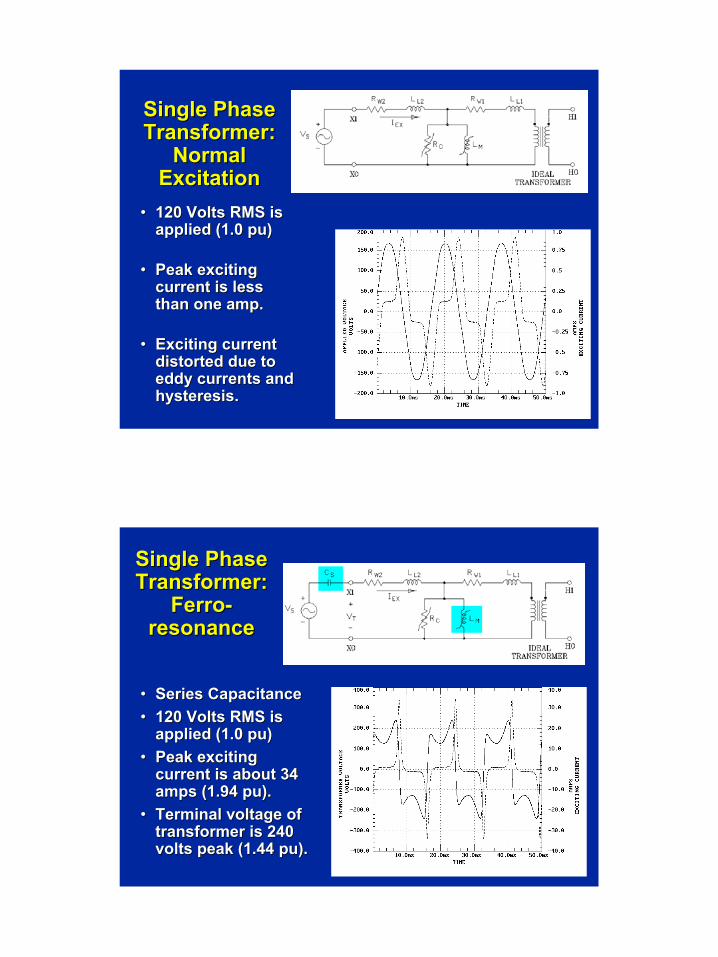
Single Phase Single Phase Transformer: Transformer:
Normal Normal ExcitationExcitation
•• 120 Volts RMS is 120 Volts RMS is applied (1.0 applied (1.0 pupu))
•• Peak exciting Peak exciting current is less current is less than one amp.than one amp.
•• Exciting current Exciting current distorted due to distorted due to eddy currents and eddy currents and hysteresishysteresis. .
Single Phase Single Phase Transformer: Transformer:
FerroFerro--resonanceresonance
•• Series CapacitanceSeries Capacitance•• 120 Volts RMS is 120 Volts RMS is
applied (1.0 applied (1.0 pupu))•• Peak exciting Peak exciting
current is about 34 current is about 34 amps (1.94 amps (1.94 pupu).).
•• Terminal voltage of Terminal voltage of transformer is 240 transformer is 240 volts peak (1.44 volts peak (1.44 pupu).).
Page 6
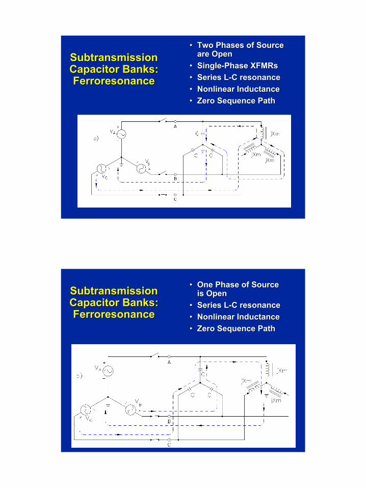
SubtransmissionSubtransmissionCapacitor Banks: Capacitor Banks: FerroresonanceFerroresonance
•• Two Phases of Source Two Phases of Source are Openare Open
•• SingleSingle--Phase Phase XFMRsXFMRs•• Series LSeries L--C resonanceC resonance•• Nonlinear InductanceNonlinear Inductance•• Zero Sequence PathZero Sequence Path
SubtransmissionSubtransmissionCapacitor Banks: Capacitor Banks: FerroresonanceFerroresonance
•• One Phase of Source One Phase of Source is Openis Open
•• Series LSeries L--C resonanceC resonance•• Nonlinear InductanceNonlinear Inductance•• Zero Sequence PathZero Sequence Path
Page 7
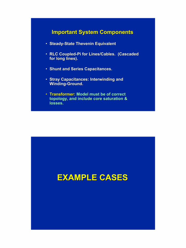
Important System ComponentsImportant System Components
•• SteadySteady--State Thevenin EquivalentState Thevenin Equivalent
•• RLC CoupledRLC Coupled--Pi for Lines/Cables. (Cascaded Pi for Lines/Cables. (Cascaded for long lines).for long lines).
•• Shunt and Series Capacitances.Shunt and Series Capacitances.
•• Stray Capacitances: Interwinding and Stray Capacitances: Interwinding and WindingWinding--Ground.Ground.
•• Transformer:Transformer: Model must be of correct Model must be of correct topology, and include core saturation & topology, and include core saturation & losses.losses.
EXAMPLE CASESEXAMPLE CASES
Page 8
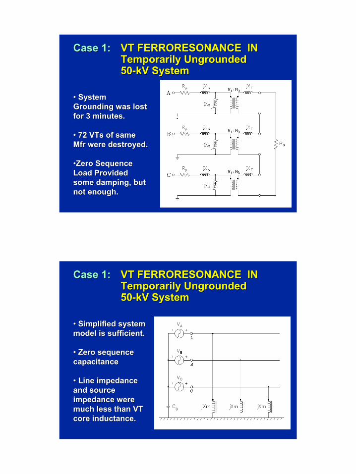
Case 1:Case 1: VT FERRORESONANCE INVT FERRORESONANCE INTemporarily Ungrounded Temporarily Ungrounded 5050--kV SystemkV System
•• System System Grounding was lost Grounding was lost for 3 minutes.for 3 minutes.
•• 72 72 VTsVTs of same of same MfrMfr were destroyed.were destroyed.
••Zero Sequence Zero Sequence Load Provided Load Provided some damping, but some damping, but not enough.not enough.
Case 1:Case 1: VT FERRORESONANCE INVT FERRORESONANCE INTemporarily Ungrounded Temporarily Ungrounded 5050--kV SystemkV System
•• Simplified system Simplified system model is sufficient.model is sufficient.
•• Zero sequence Zero sequence capacitancecapacitance
•• Line impedance Line impedance and source and source impedance were impedance were much less than VT much less than VT core inductance. core inductance.
Page 9
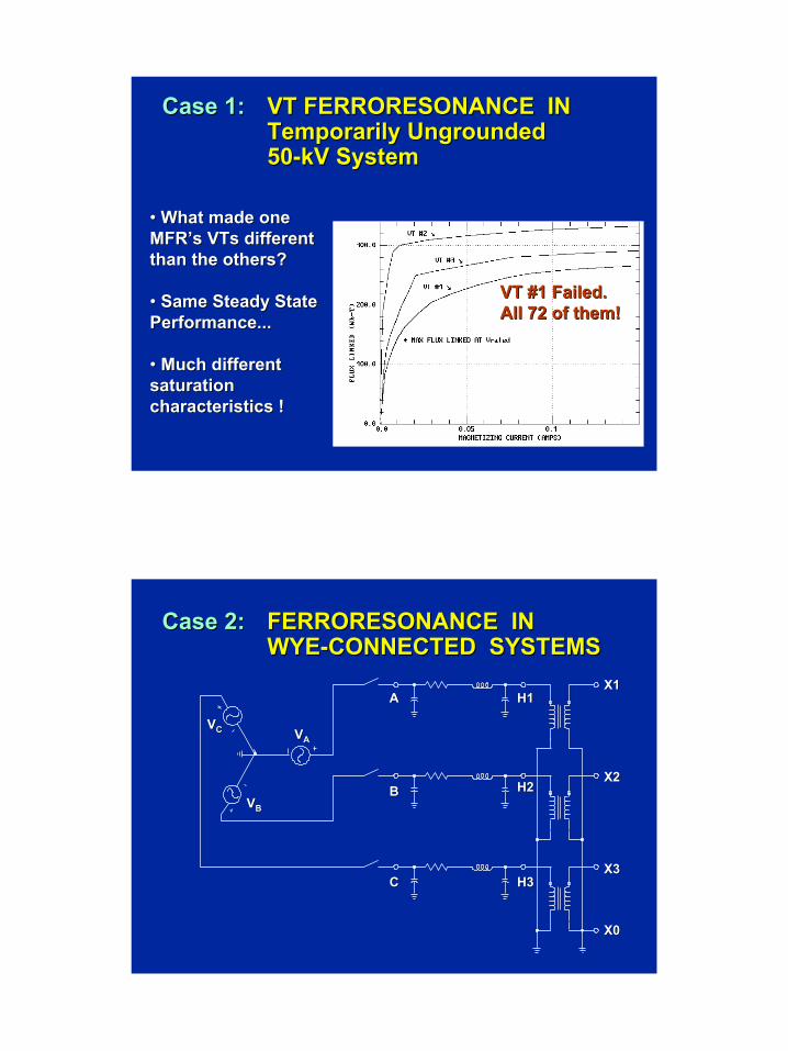
Case 1:Case 1: VT FERRORESONANCE INVT FERRORESONANCE INTemporarily Ungrounded Temporarily Ungrounded 5050--kV SystemkV System
•• What made one What made one MFR’sMFR’s VTsVTs different different than the others? than the others?
•• Same Steady State Same Steady State Performance...Performance...
•• Much different Much different saturation saturation characteristics !characteristics !
VT #1 Failed.VT #1 Failed.All 72 of them!All 72 of them!
Case 2:Case 2: FERRORESONANCE INFERRORESONANCE INWYEWYE--CONNECTED SYSTEMSCONNECTED SYSTEMS
AA
BB
CC
H1H1
H2H2
H3H3
VVAAVVCC
VVBB
X1X1
X2X2
X3X3
X0X0
Page 10
Details of Case #2Details of Case #2
•• FULL SCALE LABORATORY & FIELD TESTS.FULL SCALE LABORATORY & FIELD TESTS.•• 55--LEG WOUND CORE, RATED 75LEG WOUND CORE, RATED 75--kVAkVA, ,
WINDINGS: 12,470GY/7200 WINDINGS: 12,470GY/7200 -- 480GY/277 (TYPICAL 480GY/277 (TYPICAL IN 80% OF U.S. SYSTEMS).IN 80% OF U.S. SYSTEMS).
•• RATED VOLTAGE APPLIED.RATED VOLTAGE APPLIED.•• ONE OR TWO PHASES OPENONE OR TWO PHASES OPEN--CIRCUITED.CIRCUITED.•• BACKFEED VOLTAGE IN UNENERGIZED PHASESBACKFEED VOLTAGE IN UNENERGIZED PHASES•• CAPACITANCE(S) CONNECTED TO OPEN CAPACITANCE(S) CONNECTED TO OPEN
PHASE(S) TO SIMULATE CABLE.PHASE(S) TO SIMULATE CABLE.•• VOLTAGE WAVEFORMS ON OPEN PHASE(S) VOLTAGE WAVEFORMS ON OPEN PHASE(S)
RECORDED AS CAPACITANCE IS VARIED. RECORDED AS CAPACITANCE IS VARIED.
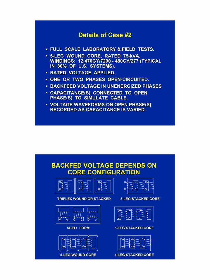
BACKFED VOLTAGE DEPENDS ON BACKFED VOLTAGE DEPENDS ON CORE CONFIGURATIONCORE CONFIGURATION
33--LEG STACKED CORELEG STACKED CORETRIPLEX WOUND OR STACKEDTRIPLEX WOUND OR STACKED
SHELL FORMSHELL FORM 55--LEG STACKED CORELEG STACKED CORE
55--LEG WOUND CORELEG WOUND CORE 44--LEG STACKED CORELEG STACKED CORE
Page 11
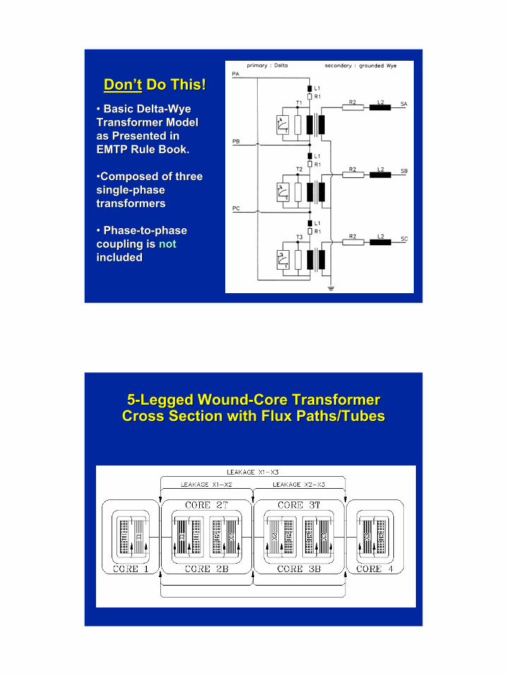
Don’tDon’t Do This! Do This! •• Basic DeltaBasic Delta--WyeWyeTransformer Model Transformer Model as Presented in as Presented in EMTP Rule Book. EMTP Rule Book.
••Composed of three Composed of three singlesingle--phase phase transformerstransformers
•• PhasePhase--toto--phase phase coupling is coupling is not not includedincluded
55--Legged WoundLegged Wound--Core Transformer Core Transformer Cross Section with Flux Paths/TubesCross Section with Flux Paths/Tubes
Page 12
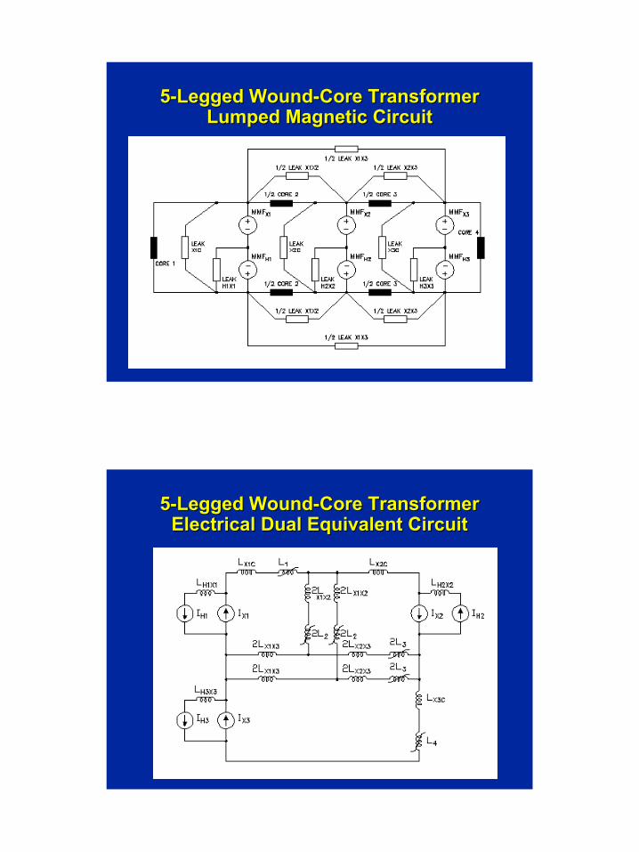
55--Legged WoundLegged Wound--Core Transformer Core Transformer Lumped Magnetic CircuitLumped Magnetic Circuit
55--Legged WoundLegged Wound--Core Transformer Core Transformer Electrical Dual Equivalent CircuitElectrical Dual Equivalent Circuit
Page 13
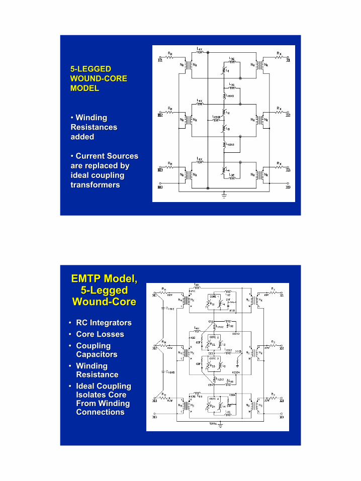
55--LEGGED LEGGED WOUNDWOUND--CORE CORE MODELMODEL
•• Winding Winding Resistances Resistances addedadded
•• Current Sources Current Sources are replaced by are replaced by ideal coupling ideal coupling transformerstransformers
EMTP Model, EMTP Model, 55--Legged Legged
WoundWound--CoreCore
•• RC IntegratorsRC Integrators•• Core LossesCore Losses•• Coupling Coupling
CapacitorsCapacitors•• Winding Winding
ResistanceResistance•• Ideal Coupling Ideal Coupling
Isolates Core Isolates Core From Winding From Winding ConnectionsConnections

Page 14
Case 2:Case 2: FERRORESONANCE INFERRORESONANCE INWYEWYE--CONNECTED SYSTEMSCONNECTED SYSTEMS
AA
BB
CC
H1H1
H2H2
H3H3
VVAAVVCC
VVBB
X1X1
X2X2
X3X3
X0X0
NONLINEAR DYNAMICAL SYSTEMS: NONLINEAR DYNAMICAL SYSTEMS: BASIC CHARACTERISTICSBASIC CHARACTERISTICS
•• MULTIPLE MODES OF RESPONSE POSSIBLE MULTIPLE MODES OF RESPONSE POSSIBLE FOR IDENTICAL SYSTEM PARAMETERS.FOR IDENTICAL SYSTEM PARAMETERS.
•• STEADY STATE RESPONSES MAY BE OF STEADY STATE RESPONSES MAY BE OF DIFFERENT PERIOD THAN FORCING DIFFERENT PERIOD THAN FORCING FUNCTION, OR NONPERIODIC (FUNCTION, OR NONPERIODIC (CHAOTICCHAOTIC).).
•• STEADY STATE RESPONSE MAY BE STEADY STATE RESPONSE MAY BE EXTREMELY EXTREMELY SENSITIVE TO INITIAL SENSITIVE TO INITIAL CONDITIONSCONDITIONS OR PERTURBATIONS .OR PERTURBATIONS .
•• BEHAVIORS CANNOT PROPERLY BE BEHAVIORS CANNOT PROPERLY BE PREDICTED BY LINEARIZED OR REDUCED PREDICTED BY LINEARIZED OR REDUCED ORDER MODELS.ORDER MODELS.
•• THEORY MATURED IN LATE 70s, EARLY 80s.THEORY MATURED IN LATE 70s, EARLY 80s.•• PRACTICAL APPLICATIONS FROM LATE 80s.PRACTICAL APPLICATIONS FROM LATE 80s.
Page 15
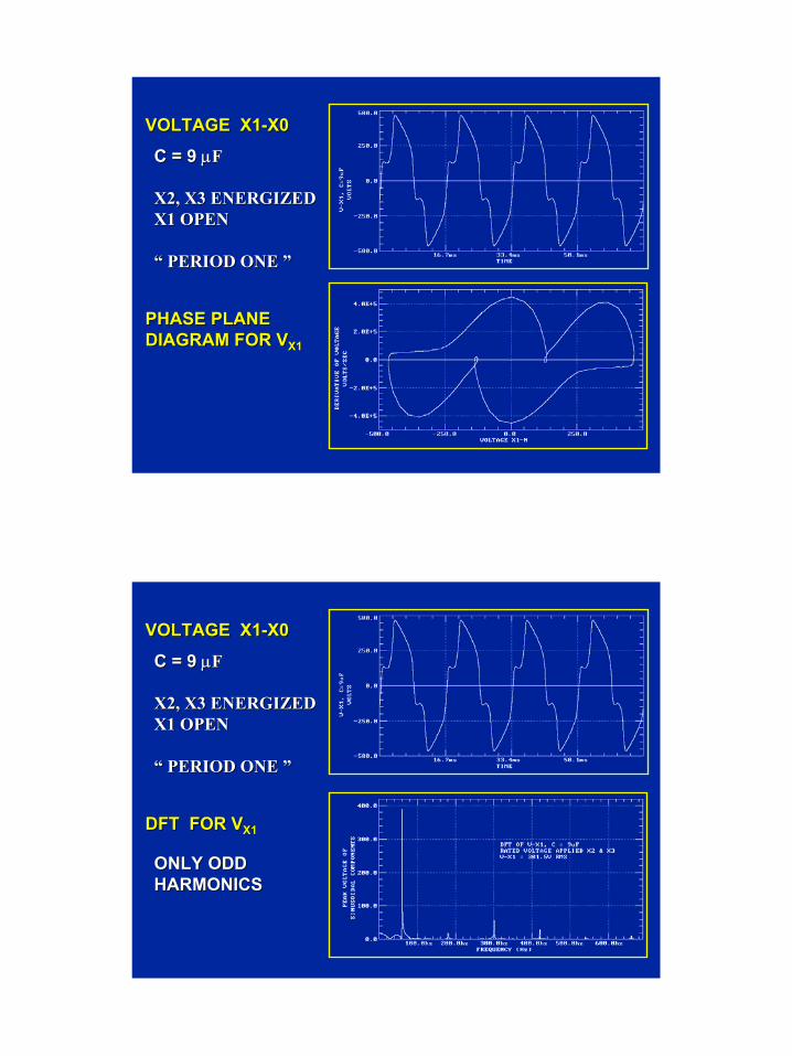
VOLTAGE X1VOLTAGE X1--X0X0
PHASE PLANEPHASE PLANEDIAGRAM FOR VDIAGRAM FOR VX1X1
C = 9 C = 9 µµFF
X2, X3 ENERGIZEDX2, X3 ENERGIZEDX1 OPENX1 OPEN
“ PERIOD ONE ”“ PERIOD ONE ”
VOLTAGE X1VOLTAGE X1--X0X0
DFT FOR VDFT FOR VX1X1
C = 9 C = 9 µµFF
X2, X3 ENERGIZEDX2, X3 ENERGIZEDX1 OPENX1 OPEN
“ PERIOD ONE ”“ PERIOD ONE ”
ONLY ODDONLY ODDHARMONICSHARMONICS
Page 16
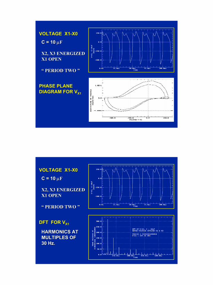
VOLTAGE X1VOLTAGE X1--X0X0
PHASE PLANEPHASE PLANEDIAGRAM FOR VDIAGRAM FOR VX1X1
C = 10 C = 10 µµFF
X2, X3 ENERGIZEDX2, X3 ENERGIZEDX1 OPENX1 OPEN
“ PERIOD TWO ”“ PERIOD TWO ”
VOLTAGE X1VOLTAGE X1--X0X0
DFT FOR VDFT FOR VX1X1
C = 10 C = 10 µµFF
X2, X3 ENERGIZEDX2, X3 ENERGIZEDX1 OPENX1 OPEN
“ PERIOD TWO ”“ PERIOD TWO ”
HARMONICS ATHARMONICS ATMULTIPLES OFMULTIPLES OF30 Hz.30 Hz.
Page 17
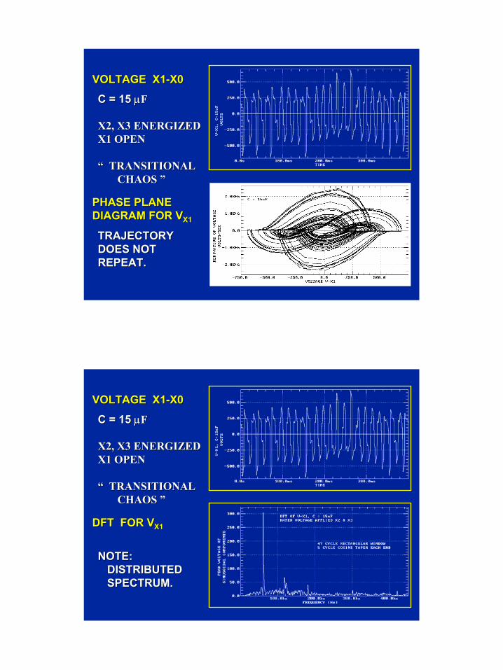
VOLTAGE X1VOLTAGE X1--X0X0
PHASE PLANEPHASE PLANEDIAGRAM FOR VDIAGRAM FOR VX1X1
C = 15 C = 15 µµFF
X2, X3 ENERGIZEDX2, X3 ENERGIZEDX1 OPENX1 OPEN
“ TRANSITIONAL“ TRANSITIONALCHAOS ”CHAOS ”
TRAJECTORYTRAJECTORYDOES NOTDOES NOTREPEAT.REPEAT.
VOLTAGE X1VOLTAGE X1--X0X0
DFT FOR VDFT FOR VX1X1
C = 15 C = 15 µµFF
X2, X3 ENERGIZEDX2, X3 ENERGIZEDX1 OPENX1 OPEN
“ TRANSITIONAL“ TRANSITIONALCHAOS ”CHAOS ”
NOTE:NOTE:DISTRIBUTEDDISTRIBUTEDSPECTRUM.SPECTRUM.
Page 18
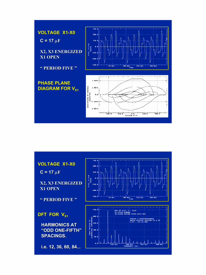
VOLTAGE X1VOLTAGE X1--X0X0
PHASE PLANEPHASE PLANEDIAGRAM FOR VDIAGRAM FOR VX1X1
C = 17 C = 17 µµFF
X2, X3 ENERGIZEDX2, X3 ENERGIZEDX1 OPENX1 OPEN
“ PERIOD FIVE ”“ PERIOD FIVE ”
VOLTAGE X1VOLTAGE X1--X0X0
DFT FOR VDFT FOR VX1X1
C = 17 C = 17 µµFF
X2, X3 ENERGIZEDX2, X3 ENERGIZEDX1 OPENX1 OPEN
“ PERIOD FIVE ”“ PERIOD FIVE ”
HARMONICS ATHARMONICS AT“ODD ONE“ODD ONE--FIFTH”FIFTH”SPACINGS.SPACINGS.
i.e. 12, 36, 60, 84...i.e. 12, 36, 60, 84...
Page 19
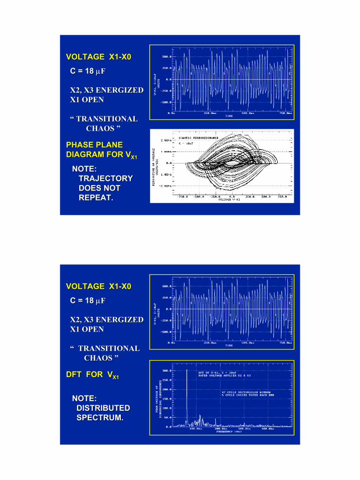
VOLTAGE X1VOLTAGE X1--X0X0
PHASE PLANEPHASE PLANEDIAGRAM FOR VDIAGRAM FOR VX1X1
C = 18 C = 18 µµFF
X2, X3 ENERGIZEDX2, X3 ENERGIZEDX1 OPENX1 OPEN
“ TRANSITIONAL“ TRANSITIONALCHAOS ” CHAOS ”
NOTE:NOTE:TRAJECTORYTRAJECTORYDOES NOTDOES NOTREPEAT.REPEAT.
VOLTAGE X1VOLTAGE X1--X0X0
DFT FOR VDFT FOR VX1X1
C = 18 C = 18 µµFF
X2, X3 ENERGIZEDX2, X3 ENERGIZEDX1 OPENX1 OPEN
“ TRANSITIONAL“ TRANSITIONALCHAOS ” CHAOS ”
NOTE:NOTE:DISTRIBUTEDDISTRIBUTEDSPECTRUM.SPECTRUM.
Page 20
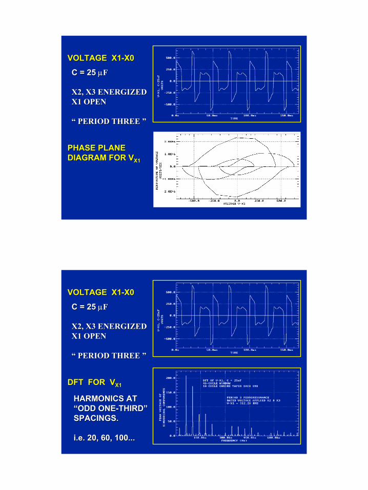
VOLTAGE X1VOLTAGE X1--X0X0
PHASE PLANEPHASE PLANEDIAGRAM FOR VDIAGRAM FOR VX1X1
C = 25 C = 25 µµFF
X2, X3 ENERGIZEDX2, X3 ENERGIZEDX1 OPENX1 OPEN
“ PERIOD THREE ”“ PERIOD THREE ”
VOLTAGE X1VOLTAGE X1--X0X0
DFT FOR VDFT FOR VX1X1
C = 25 C = 25 µµFF
X2, X3 ENERGIZEDX2, X3 ENERGIZEDX1 OPENX1 OPEN
“ PERIOD THREE ”“ PERIOD THREE ”
HARMONICS ATHARMONICS AT“ODD ONE“ODD ONE--THIRD”THIRD”SPACINGS.SPACINGS.
i.e. 20, 60, 100...i.e. 20, 60, 100...
Page 21
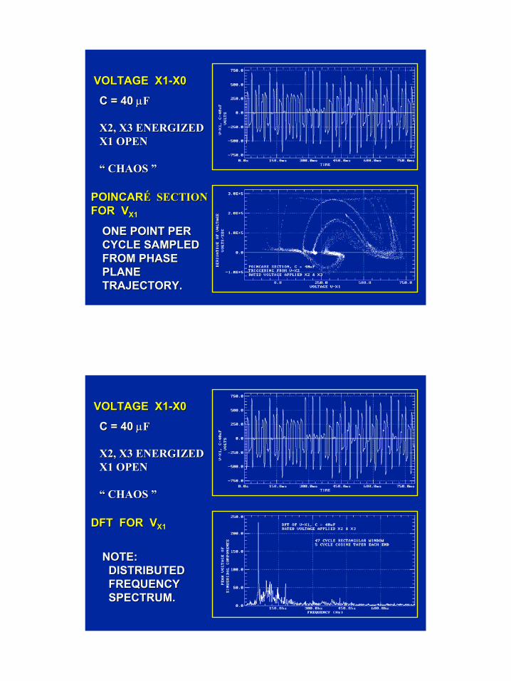
VOLTAGE X1VOLTAGE X1--X0X0
POINCARPOINCARÉ SECTIONÉ SECTIONFOR VFOR VX1X1
C = 40 C = 40 µµFF
X2, X3 ENERGIZEDX2, X3 ENERGIZEDX1 OPENX1 OPEN
“ CHAOS ” “ CHAOS ”
ONE POINT PERONE POINT PERCYCLE SAMPLEDCYCLE SAMPLEDFROM PHASEFROM PHASEPLANE PLANE TRAJECTORY.TRAJECTORY.
VOLTAGE X1VOLTAGE X1--X0X0
DFT FOR VDFT FOR VX1X1
C = 40 C = 40 µµFF
X2, X3 ENERGIZEDX2, X3 ENERGIZEDX1 OPENX1 OPEN
“ CHAOS ” “ CHAOS ”
NOTE:NOTE:DISTRIBUTEDDISTRIBUTEDFREQUENCYFREQUENCYSPECTRUM.SPECTRUM.
Page 22
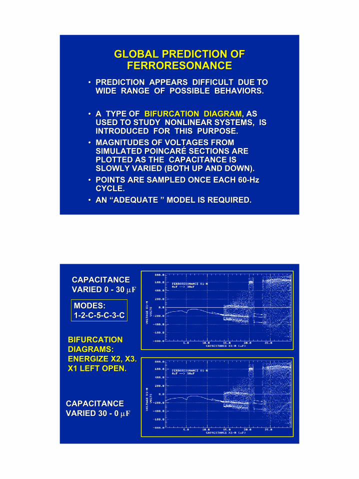
GLOBAL PREDICTION OF GLOBAL PREDICTION OF FERRORESONANCEFERRORESONANCE
•• PREDICTION APPEARS DIFFICULT DUE TO PREDICTION APPEARS DIFFICULT DUE TO WIDE RANGE OF POSSIBLE BEHAVIORS. WIDE RANGE OF POSSIBLE BEHAVIORS.
•• A TYPE OF A TYPE OF BIFURCATION DIAGRAMBIFURCATION DIAGRAM, AS , AS USED TO STUDY NONLINEAR SYSTEMS, IS USED TO STUDY NONLINEAR SYSTEMS, IS INTRODUCED FOR THIS PURPOSE.INTRODUCED FOR THIS PURPOSE.
•• MAGNITUDES OF VOLTAGES FROM MAGNITUDES OF VOLTAGES FROM SIMULATED POINCARÉ SECTIONS ARE SIMULATED POINCARÉ SECTIONS ARE PLOTTED AS THE CAPACITANCE IS PLOTTED AS THE CAPACITANCE IS SLOWLY VARIED (BOTH UP AND DOWN). SLOWLY VARIED (BOTH UP AND DOWN).
•• POINTS ARE SAMPLED ONCE EACH 60POINTS ARE SAMPLED ONCE EACH 60--Hz Hz CYCLE. CYCLE.
•• AN “ADEQUATE ” MODEL IS REQUIRED.AN “ADEQUATE ” MODEL IS REQUIRED.
BIFURCATIONBIFURCATIONDIAGRAMS:DIAGRAMS:ENERGIZE X2, X3.ENERGIZE X2, X3.X1 LEFT OPEN.X1 LEFT OPEN.
CAPACITANCECAPACITANCEVARIED 0 VARIED 0 -- 30 30 µµFF
CAPACITANCECAPACITANCEVARIED 30 VARIED 30 -- 0 0 µµFF
MODES:MODES:11--22--CC--55--CC--33--CC
Page 23
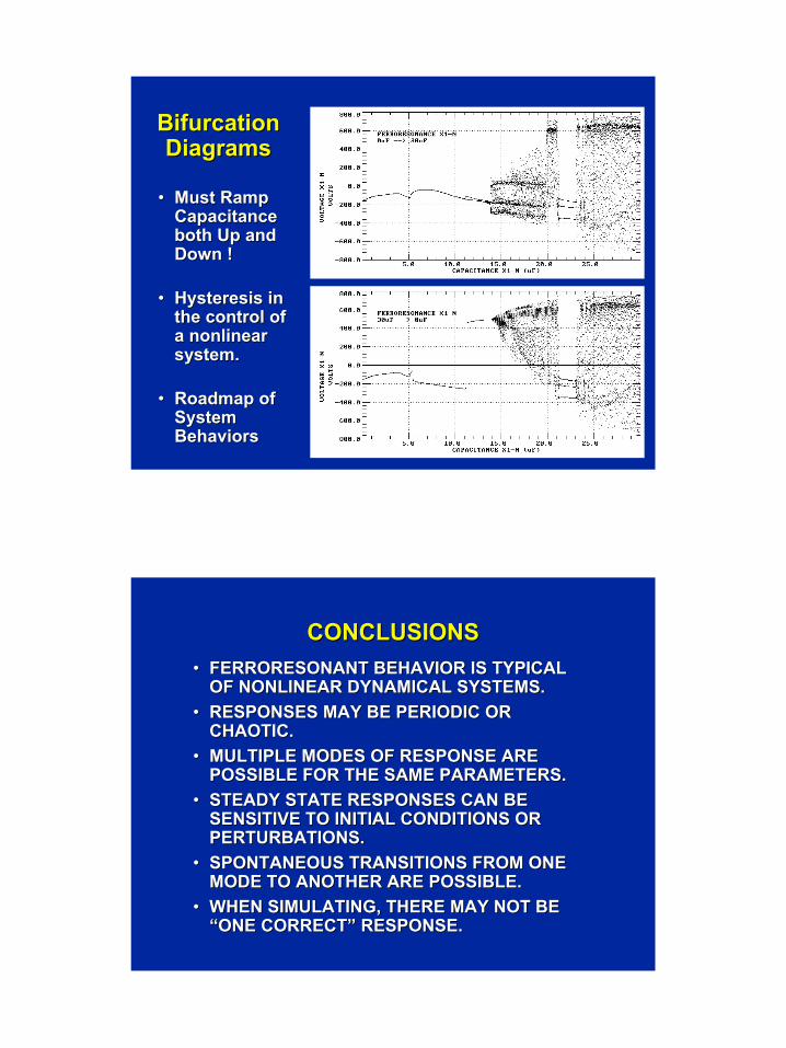
Bifurcation Bifurcation DiagramsDiagrams
•• Must Ramp Must Ramp Capacitance Capacitance both Up and both Up and Down !Down !
•• Hysteresis Hysteresis in in the control of the control of a nonlinear a nonlinear system.system.
•• Roadmap of Roadmap of System System BehaviorsBehaviors
CONCLUSIONSCONCLUSIONS•• FERRORESONANT BEHAVIOR IS TYPICAL FERRORESONANT BEHAVIOR IS TYPICAL
OF NONLINEAR DYNAMICAL SYSTEMS.OF NONLINEAR DYNAMICAL SYSTEMS.•• RESPONSES MAY BE PERIODIC OR RESPONSES MAY BE PERIODIC OR
CHAOTIC.CHAOTIC.•• MULTIPLE MODES OF RESPONSE ARE MULTIPLE MODES OF RESPONSE ARE
POSSIBLE FOR THE SAME PARAMETERS.POSSIBLE FOR THE SAME PARAMETERS.•• STEADY STATE RESPONSES CAN BE STEADY STATE RESPONSES CAN BE
SENSITIVE TO INITIAL CONDITIONS OR SENSITIVE TO INITIAL CONDITIONS OR PERTURBATIONS.PERTURBATIONS.
•• SPONTANEOUS TRANSITIONS FROM ONE SPONTANEOUS TRANSITIONS FROM ONE MODE TO ANOTHER ARE POSSIBLE.MODE TO ANOTHER ARE POSSIBLE.
•• WHEN SIMULATING, THERE MAY NOT BE WHEN SIMULATING, THERE MAY NOT BE “ONE CORRECT” RESPONSE.“ONE CORRECT” RESPONSE.
Page 24
CONCLUSIONS (CONT’D)CONCLUSIONS (CONT’D)
•• BIFURCATIONS OCCUR AS CAPACITANCE IS BIFURCATIONS OCCUR AS CAPACITANCE IS VARIED UPWARD OR DOWNWARD.VARIED UPWARD OR DOWNWARD.
•• PLOTTINGPLOTTING Vpeak vsVpeak vs. CAPACITANCE OR . CAPACITANCE OR OTHER VARIABLES GIVES DISCONTINUOUS OTHER VARIABLES GIVES DISCONTINUOUS OR MULTIOR MULTI--VALUED FUNCTIONS.VALUED FUNCTIONS.
•• THEREFORE, SUPPOSITION OF TRENDS THEREFORE, SUPPOSITION OF TRENDS BASED ON LINEARIZING A LIMITED SET OF BASED ON LINEARIZING A LIMITED SET OF DATA IS PARTICULARLY PRONE TO ERROR.DATA IS PARTICULARLY PRONE TO ERROR.
•• BIFURCATION DIAGRAMS PROVIDE A ROAD BIFURCATION DIAGRAMS PROVIDE A ROAD MAP, AVOIDING NEED TO DO SEPARATE MAP, AVOIDING NEED TO DO SEPARATE SIMULATIONS AT DISCRETE VALUES OF SIMULATIONS AT DISCRETE VALUES OF CAPACITANCE AND INITIAL CONDITIONS. CAPACITANCE AND INITIAL CONDITIONS.
RecommendationsRecommendations•• Beware of lightlyBeware of lightly--loaded transformers loaded transformers
operating in the presence of capacitance.operating in the presence of capacitance.•• Topologically correct transformer models are Topologically correct transformer models are
the key to simulation of ferroresonance.the key to simulation of ferroresonance.•• Core saturation/loss representations are still Core saturation/loss representations are still
weak point of transformer models.weak point of transformer models.•• Nonlinearities make ferroresonance hard to Nonlinearities make ferroresonance hard to
predict or confirm. predict or confirm. •• Monitor current literature for new Monitor current literature for new
developments in modeling and simulation developments in modeling and simulation techniques.techniques.

Page 25
COMMENTS?COMMENTS?
QUESTIONS?QUESTIONS?