Embed Size (px)
Citation preview

F
Moeller Wiring Manual 02/05
Automation Systems
or Immediate Deliv
1
Page
Programmable logic controllers PLCs 1-2
xSystem 1-4
Modular I/O system XI/ON 1-6
Networkable motor starters xStart-XS1 1-8
Networking PS40 series 1-10
Networking xSystem 1-11
Networking display and operating devices 1-12
Networking embedded HMI-PLCs 1-13
Engineering XC100/XC200 1-14
Engineering PS4 1-16
Engineering EM4 and LE4 1-19
1-1ery call KMParts.com at (866) 595-9616

Moeller Wiring Manual 02/05
1
F
Automation SystemsProgrammable Logic Controllers, PLCs
Programmable logic controllers
The programmable (logic) controller (PLC) is an electronic device for machine or process control. The PLC receives signals via inputs, processes them according to the instructions of a program, and transfers signals to the outputs.The program is created using programming software which is able to link inputs and outputs in any required sequence, to measure time, or even carry out arithmetic operations.
The most important specifications of a PLC are its maximum number of inputs/outputs, its memory size and its processing speed.The PS40 Series and the new xSystem are the two automation systems offered by Moeller. These are described below.
PS40 Series
Compact PLCsThe PS4 compact PLCs have the following system characteristics:• Standard programming• Remote and local expansion options• Integrated fieldbus interface (Suconet)• Plug-in screw terminals• Small, compact in sizeThe controllers in this range are very versatile with a wide range of features, such as integrated setpoint potentiometers, analog inputs/outputs or memory expansion modules (from PS4-150).
Moellers' entire PLC range is described in the Main Catalogue for Automation Systems and Drives, as well as in the Product overview for automation.
Modular PLCsThe PS416 modular PLC has the following key features:• High processing speed• Compact size• Wide range of networking options• Extensive memory
Sucosoft programming softwareSucosoft is the name of the software for programming the PS40 PLCs.Program examples are provided in the PLC Beginners' Guide “Automation with Programmable Logic Controllers” (FB2700-017).
1-2or Immediate Delivery call KMParts.com at (866) 595-9616

Automation SystemsProgrammable Logic Controllers, PLCs
Moeller Wiring Manual 02/05
F
1
PS4/EM4:Compact PLC or expansion module
LE4:Local expansion
PS416: Modular PLC
1-3or Immediate Delivery call KMParts.com at (866) 595-9616

Moeller Wiring Manual 02/05
1
F
Automation SystemsxSystem
xSystem
xSystem is Moeller's latest modular automation system. It can be configured for the individual requirements of small or large applications. xSystem reduces the hardware and software interfaces required. The system features IT functions that are already integrated.
The XSoft software combines programming, configuring, testing, commissioning and visualization functions in a single tool designed for the entire xSystem product range.
DC INPUT EH-XD16
04812
15913
26
1014
37
1115
DC INPUT EH-XD16
04812
15913
26
1014
37
1115
DC INPUT EH-XD16
04812
15913
26
1014
37
1115
DC INPUT EH-XD16
04812
15913
26
1014
37
1115
DC INPUT EH-XD16
04812
15913
26
1014
37
1115
DC INPUT EH-XD16
04812
15913
26
1014
37
1115
DC INPUT EH-XD16
04812
15913
26
1014
37
1115
XC-CPU101
0404
1515
26214
37315
2
5
8
F5
1
4
7
F4
0
,
+/-
F3
F15
F13
F11
F2
F14
F12
F10
F1
3 ESCENTER
CLEAR
SHIFT6
9
F6 F7 F8 F9
2
A B C3
D E F
F5
F8
F7
F6
F4
F3
F2
F1
ESCENTER
CLEAR
SHIFT
1
5
J K L6
M N O
4
G H I
8
T U V
. +/-
9
W X Y Z
7
P Q R S
0
XC-CPU101
0404
1515
26214
37315
XC-CPU201
0404
1515
26214
37315
1
8
7
8
1
2
180˚
3
3
1-4or Immediate Delivery call KMParts.com at (866) 595-9616
Automation SystemsxSystem
Moeller Wiring Manual 02/05
F
1
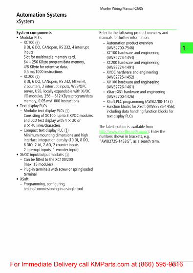
System components • Modular PLCs
– XC100 h 8 DI, 6 DO, CANopen, RS 232, 4 interrupt inputsSlot for multimedia memory card, 64 – 256 KByte program/data memory, 4/8 KByte for retentive data, 0.5 ms/1000 instructions
– XC200 g 8 DI, 6 DO, CANopen, RS 232, Ethernet, 2 counters, 2 interrupt inputs, WEB/OPC server, USB, locally expandable with XI/OC I/O modules, 256 – 512 KByte program/data memory, 0.05 ms/1000 instructions
• Text display PLCs– Modular text display PLCs a
Consisting of XC100, up to 3 XI/OC modules and LCD text display with 4 x 20 or 8 x 40 lines/characters
– Compact text display PLC b Minimum mounting dimensions and high interface integration density (10 DI, 8 DO, 8 DIO, 2 AI, 2 AO, 2 counter inputs, 2 interrupt inputs, 1 encoder input)
• XI/OC input/output modules c– Can be fitted to the XC100/200
(max. 15 modules)– Plug-in terminals with screw or springloaded
terminal• XSoft
– Programming, configuring, testing/commissioning in a single tool
Refer to the following product overview and manuals for further information:
– Automation product overview (AWB2700-7546)
– XC100 hardware and engineering (AWB2724-1453)
– XC200 hardware and engineering (AWB2724-1491)
– XI/OC hardware and engineering (AWB2725-1452)
– XV100 hardware and engineering (AWB2726-1461)
– xStart-XS1 hardware and engineering (AWB2700-1426)
– XSoft PLC programming (AWB2700-1437)– Function blocks for XSoft (AWB2786-1456);
including data handling function blocks for text display PLCs
The latest edition is available from http://www.moeller.net/support: Enter the numbers shown in brackets, e.g. “AWB2725-1452G”, as a search term.
1-5or Immediate Delivery call KMParts.com at (866) 595-9616

Moeller Wiring Manual 02/05
1
F
Automation SystemsModular I/O System XI/ON
XI/ON – the concept
XI/ON is a modular I/O system for use in industrial automation applications. It links sensors and actuators on the field level with the higher-level controller. Fieldbus protocols PROFIBUS-DP, CANopen and DeviceNet are supported.XI/ON offers modules for virtually every application:• Digital input and output modules• Analog input and output modules• Technology modulesA XI/ON station consists of a gateway, power supply modules and I/O modules.
A complete XI/ON structure counts as a single bus station in any fieldbus structure and therefore only requires one bus address. The individual XI/ON peripheral modules are therefore independent of the higher-level fieldbus.The I/O modules consist of a combination of a base module designed as a terminal block, and a plug-in electronics module.The XI/ON peripheral modules are linked to the fieldbus via the XI/ON gateway. This is used for the communication between the XI/ON station and the other fieldbus stations.
a Gatewayb Power supply modulec Electronics module in block designd Electronics module in slice design
e End platef Base module in slice designg Base module in block design
b
a
d
e
f
c
g
1-6or Immediate Delivery call KMParts.com at (866) 595-9616

Automation SystemsModular I/O System XI/ON
Moeller Wiring Manual 02/05
F
1
Flexibility Each XI/ON station can be adapted exactly for the required number of channels since the modules are available in different levels of granularity.For example, digital input modules with 2, 4, 16 or 32 channels are available in slice or block design.A XI/ON station can contain modules in any combination. This enables the system to be adapted to virtually any application in industrial automation.
Compact designThe narrow mounting width of the XI/ON modules (gateway 50.4 mm; slice 12.6 mm, block 100.8 mm) and the low mounting height make the system ideal for use in applications where space is at a premium.
Simple handlingApart from the gateway, all XI/ON modules consist of a base module and an electronics module.The gateway and the base modules can be snap-fitted on mounting rails. The electronics
modules can then be plugged simply onto the assigned base module.The base modules are available as terminal blocks. They are wired either with spring-loaded or screw terminals. The electronic modules can be fitted or removed during commissioning or for maintenance without disturbing the wiring.A design coding feature ensures that the electronic modules can only be fitted at the correct locations provided.
I/Oassistant diagnostics and engineering softwareThe I/Oassistant provides support during the entire planning and implementation phase of an I/O system. It provides help for engineering the stations, the configuration and for setting the parameters. The software is used for commissioning systems and carrying out tests and diagnostics on the stations.The entire documentation for the station, including a parts list for ordering, can be generated after the engineering phase.
1-7or Immediate Delivery call KMParts.com at (866) 595-9616

Moeller Wiring Manual 02/05
1
F
Automation SystemsNetworkable Motor Starters xStart-XS1
xStart-XS1
xStart-XS1 is the modular, networkable version of the tried and tested motor starter from Moeller. It connects the motors with the XI/ON system and thus ensures flexible availability between systems, irrespective of the fieldbus in use.xStart-XS1 offers DOL and reversing starters in different ratings and available with or without a trip-indicating auxiliary contact (AGM).
The xStart-XS1 modules consist of a base module and a power module that contains the tried and tested PKZM0 motor-protective circuit-breaker and one or two DILEM contactors. They enable the connection of assigned motor ratings up to 4.0 kW at a rated operational voltage Ue of 400 V AC.
FlexibilityYou can adapt xStart-XS1 exactly to the requirements of the system used.xStart-XS1 can be used at any position on a XI/ON station so that you can organise your station conveniently into system areas.The motor can be disconnected at the machine by using the rotary handle.
MountingThe complete module is mounted by simply snap-fitting it onto two top-hat rails. You can also simply mount the base module and add the power section at a later time. Mounting and removal are carried out without any tools.
a XI/ON gatewayb Supply modulec XI/ON I/O modulesd xStart-XS1 DOL
starter modulee xStart-XS1 reversing
starter module
a
b c cbd e d
1-8or Immediate Delivery call KMParts.com at (866) 595-9616

Automation SystemsNetworkable Motor Starters xStart-XS1
Moeller Wiring Manual 02/05
F
1
Power supply accessories are available for reducing wiring costs. If several xStart-XS1 modules are mounted next to each other, the
power can be fed via a distribution system. This power distribution is available for an operating current of up to 63 A.
125
3
4
2
1
a Incoming terminal for three-phase commoning link
b Three-phase commoning link for up to 4 DOL starters without trip-indicating auxiliary contact AGM
c DOL starter without AGM trip-indicating auxiliary contact
PEPEPEPE MMMM3 h3 h3 h3 h
L1L2L3
a
b
c
1-9or Immediate Delivery call KMParts.com at (866) 595-9616

Moeller Wiring Manual 02/05
1
F
Automation SystemsNetworking PS40 Series
max. 6 LE4
PRO
FIBU
S-FM
S
Suco
net
PRO
FIBU
S-DP
PS4-141-MM1PS4-151-MM1
PS4-201-MM1PS4-271-MM1PS4-341-MM1
PS416-BGT...PS416-CPU...PS416-POW...PS416-INP...PS416-OUT...PS416-AIN...PS416-AIO...PS416-CNT-200PS416-TCS-200PS416-NET...PS416-COM-200PS416-MOD-200
EM4-101-...EM4-111-...
EM4-201-DX2
LE4-104-XP1LE4-108-...LE4-116-...LE4-206-...LE4-308-...LE4-622-CX1
LE4-501-BS1LE4-503-BS1
CM4-504-GS1CM4-505-GS1ZB4-501-UM4
S40
Suconet K + RS 232Suconet K + RS 232
Suconet K + RS 232Suconet K + RS 232Suconet K + RS 232
Suconet K (M/S)
Modbus(SI)
Suconet K/K1Suconet K/K1
Suconet KEM4-204-DX1 PROFIBUS-DP
Suconet KLE4-633-CX1
PROFIBUS-FMS (Slave)
Suconet K, PROFIBUS-DPGateway
Mod
bus
64 kByte64 kByte
64 kByte64 kByte512 kByte
PS40
Ran
ge
Part No. Interface
serial interface
interface converter
Programming software
Memory
2 x 3 counter3 x 3 path measurement
1-10or Immediate Delivery call KMParts.com at (866) 595-9616

Moeller Wiring Manual 02/05
F
Automation SystemsNetworking xSystem
1
XC200+ XIOC
XC100+ XIOC
XC100-XV+ XV100
CANo
pen
xSys
tem
Ethe
rnet
PROF
IBUS
-DP
Suco
net K
Mod
bus
XC600
1-11or Immediate Delivery call KMParts.com at (866) 595-9616

Moeller Wiring Manual 02/05
1
F
Automation SystemsNetworking Display and Operator Devices
MI4-110-KC1MI4-110-KD1MI4-110-KG1/2MI4-140-KF1MI4-140-KI1MI4-140-KJ1
120 X 32 1119
CAN
open
Suco
net
Ethe
rnet
PRO
FIBU
S-DP
Devi
ceN
et
120 X 32
120 X 64240 X 64240 X 64
120 X 32 3527
MI4-150-KI1MI4-450-KI1
320 X 240 5656 320 X 240
MI4-570-KH1 640 X 480 50
4646
MI4-140-TA1MI4-450-TA1MI4-550-TA1MI4-160-TA1MI4-570-TA2
320 X 240 ––320 X 240
640 X 480640 X 480
320 X 240 –––
MI4-580-TA1MI4-590-TA1 1024 X 768
800 X 600 ––
MI4-130-TA1 320 X 240 –
Part no Display
Text operator panel M14
Resolution Code
Graphic operator panel M14
LCD monochromeLCD monochromeLCD monochromeLCD monochromeLCD monochromeLCD monochrome
MonochromeSTN colourTFT
Touch operator panel M14 (Resistive)
MonochromeSTN colourTFT colourMonochromeTFT
Touch operator panel MV4 (Infra-red)
TFTTFT
h
Monochrome
HM
I (D
ispl
ay a
nd o
pera
ting
dev
ice)
1-12or Immediate Delivery call KMParts.com at (866) 595-9616
Moeller Wiring Manual 02/05
F
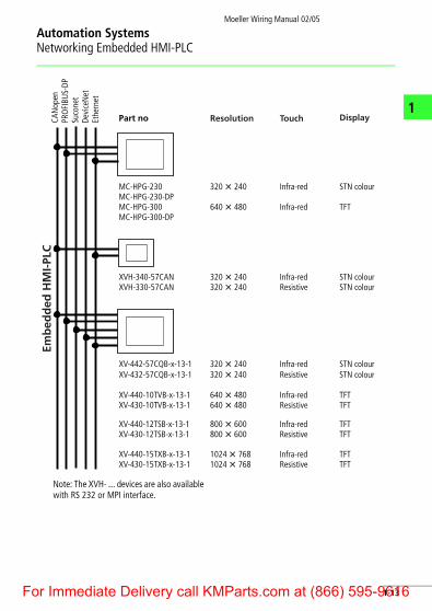
Automation SystemsNetworking Embedded HMI-PLC
1
Note: The XVH- ... devices are also available with RS 232 or MPI interface.
MC-HPG-230MC-HPG-230-DPMC-HPG-300MC-HPG-300-DP
320 X 240
CAN
open
Suco
net
Ethe
rnet
PRO
FIBU
S-DP
Devi
ceN
et
640 X 480
XVH-340-57CANXVH-330-57CAN
320 X 240320 X 240
XV-432-57CQB-x-13-1
XV-440-10TVB-x-13-1XV-430-10TVB-x-13-1
320 X 240
640 X 480640 X 480
XV-440-12TSB-x-13-1XV-430-12TSB-x-13-1
800 X 600800 X 600
XV-440-15TXB-x-13-1XV-430-15TXB-x-13-1
1024 X 7681024 X 768
XV-442-57CQB-x-13-1 320 X 240
Part no
Infra-red
DisplayResolution Touch
Infra-red
Infra-redResistive
Resistive
Infra-redResistive
Infra-redResistive
Infra-redResistive
Infra-red
STN colour
TFT
STN colourSTN colour
STN colour
TFTTFT
TFTTFT
TFTTFT
STN colour
Emb
edd
ed H
MI-
PLC
1-13or Immediate Delivery call KMParts.com at (866) 595-9616

Moeller Wiring Manual 02/05
1
F
Automation SystemsEngineering XC100/XC200
Device arrangement
Install the rack and the PLC horizontally in the control cabinet – as shown in the following figure.
Terminal assignment The terminals for the power supply and the local I/O have the following assignment:
Wiring example of power supply unit The voltage terminal 0VQ/24VQ is only used for the power supply of the local 8 inputs and 6 outputs, and is potentially isolated from the bus.The outputs 0 to 3 can be loaded with 500 mA and the outputs 4 and 5 with 1 A, each with a 100 % duty factor (DF) and a simultaneity factor of 1.The wiring example shows the wiring with a separate power supply for the PLC and the IO terminals. If only one power supply is used, the following terminals must be connected:24 V to 24VQ and 0 V to 0VQ.
a Clearance > 50 mmb Clearance > 75 mm from
active elementsc Cable duct
c
ba
bab
a
b
a
%IX 0.0%IX 0.1
%IX 0.2%IX 0.3
%IX 0.4%IX 0.5
%IX 0.6%IX 0.7
%QX 0.0%QX 0.1
%QX 0.2%QX 0.3
%QX 0.4%QX 0.5
24 VQ0 VQ
0 V24 V
1-14or Immediate Delivery call KMParts.com at (866) 595-9616

Automation SystemsEngineering XC100/XC200
Moeller Wiring Manual 02/05
F
1
RS 232 serial interface This interface is used by the XC100 to communicate with the PC. The physical connection is implemented via an RJ 45 interface. The interface is not isolated. The connector has the following assignment:
You can use the COM1 or COM2 interface on the PC.
You use the XT-SUB-D/RJ45 programming cable for the physical connection.
CANopen interface Assignment of the 6-pole Combicon connector:
Only use a cable that is permissible for CANopen with the following properties:• Surge impedance 108 to 132 O • Capacitance per unit length < 50 pF/m
Pin Designation Description
4 GND Ground
5 TxD Transmit Data
7 GND Ground
8 RxD Receive Data
+ 24 V H0 V H
+ 24 VQ H0 VQ H
0246024
1357135
8
7
6
5
4
3
2
1
Terminal Signal
6 GND
5 CAN_L
4 CAN_H
3 GND
2 CAN_L
1 CAN_H
Baud
rat
e [K
bit/
s]
Len
gth
[m]
Cabl
e cr
oss s
ecti
on
[mm
2 ]
Loop
res
ista
nce
[O/k
m]
20 1000 0.75 – 0.80 16
125 500 0.50 – 0.60 40
250 250 0.50 – 0.60 40
500 100 0.34 – 0.60 60
1000 40 0.25 – 0.34 70
654321
CAN_H
CAN_GNDCAN_L
CAN_H
CAN_GNDCAN_L
120 O
120 O
1-15or Immediate Delivery call KMParts.com at (866) 595-9616

Moeller Wiring Manual 02/05
1
F
Automation SystemsEngineering PS4
PS4-151-MM1 compact PLC
• Wiring for a 230 V AC supply circuit• Relay contacts with different potentials: 230 V
AC and 24 V DC
• 24 V DC inputs from an external power supply unit, earthed operation
* Insulation monitoring must be provided where the control circuits are not earthed. (EN 60204-1 and VDE 0100-725)
** IEC/EN 60204-1 specifies that a control transformer is required.
L2
N
**
Q1
1
*
2
1
F1
T1MM
0 V+24 V
T2
2
1
L1 N PE
F2
*
+24 V
B1
0 V
A
+24 V
B2
0 V
A
X1
1
PRG Suconet K
NL1 0 V.0 .1 .2 .3 .4 .5 .6 .7
0 V
II
2
A1
24 V 0 V.0 .1 .2 .3 .4 .5 .6 .7
I
RR
24 V
.0 .1 .2 .3 .4 .5 .6 .7U10
U1U0
IA/QA
A1
A2Q12
M1
A1
A2
F7
A1
A2
A1
A2Q13
A1
A2Q14
A1
A2
P2A1
A2Q11
X1
X2
P1
F6F5F3 F4
2.5 mm 2
L3
PE
L1
31
2
Q21 5
2 4 6I >I > I >
1-16or Immediate Delivery call KMParts.com at (866) 595-9616

Automation SystemsEngineering PS4
Moeller Wiring Manual 02/05
F
1
PS4-201-MM1 compact PLC
• Shared power supply for PLC and inputs/outputs
• Non-earthed operation with insulation monitoring
* For operation without insulation monitoring, 0 V must be linked with the PE potential in the control circuits.
3
S2L1
L2
NL3
PE
L1
1
2
13 23 33
14
Q11 Q1124 34
0 V+24 V
T1
PEL2 L3
3L144
0 V+24 V
T2
N PE
43
2
1
F1C1 C1
A1
A2Q11
A1
A2
2
1
F2
11
22
14P1
21
S1
14
13
2
1
F3
P1
A1
A2
1
PRG Suconet K
0 V
24 V 0 V
+24 V
22
1
F41
F5
13
14
S313
14
B4
0 V
.0 .1 .2 .3 .4 .5 .6 .7
.0 .1 .2 .3 .4 .5
A
0 V
U10
II
Q
2
A1
A1
A2Q12 Q13 M1
A1
A2
0 V+24 V24
V
U0 U1
Q11 5
2 4 6I >I > I >
A1
A2
12
*
1-17or Immediate Delivery call KMParts.com at (866) 595-9616

Automation SystemsEngineering PS4
Moeller Wiring Manual 02/05
1
F
PS4-341-MM1 compact PLC
• Shared power supply for PLC and inputs/outputs
• Non-earthed operation with insulation monitoring
* For operation without insulation monitoring, 0 V must be linked with the PE potential in the control circuits.
3
S2L1
L2
NL3
PE
L1
1
2
13 23 33
14
Q1124 34
0 V+24 V
T1
PEL2 L3
3L144
Q11
0 V+24 V
T2
N PE
43
2
1
F1C1 C1
A1
A2Q11
A1
A2
2
1
F2
11
22
14P1
21
S1
14
13
2
1
F3
P1
A1
A2
F4 F5 F6
0 V+24 V
Q11 5
2 4 6I >I > I >
12
1 2
0 V I
0 V I.0 .1 .2 .3 .4 .5 .6 .7
Digital Input
Digital Output
Digital Input
Digital OutputDigital InputPRG Suconet K
24 V 0 V
0 V A
.0 .1 .2 .3 .4 .5
.0 .1 .2 .3 .4 .5 .6 .7
0 V Q
.0 .1 .2 .3 .4 .5 .6 .7 24 V
U 0 U 1 U 10
a *
1-18or Immediate Delivery call KMParts.com at (866) 595-9616
Moeller Wiring Manual 02/05
F
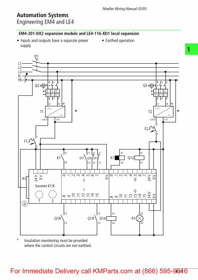
Automation SystemsEngineering EM4 and LE4
1
EM4-201-DX2 expansion module and LE4-116-XD1 local expansion
• Inputs and outputs have a separate power supply
• Earthed operation
* Insulation monitoring must be provided where the control circuits are not earthed.
PE
0 V+24 V
T1
L1 N PE
L2
N
Q1
1
L3
L1
2
1
F1
2
1
F2
A1
1
Suconet K1/K
0 V
24 V 0 V.0 .1 .2 .3 .4 .5 .6 .7
II
I
2
0 V.0 .1 .2 .3 .4 .5 .6 .7
Q
24 V
.8 .9 .10
.11
.12
.13
.14
.15
.8 .9 .10
.11
.12
.13
.14
.15
24 V
0 V
Q
Q12K112
11
14
13
12
11
Q15 Q16 Q17
15
K118
13
Q1814
13
Q1914
Q14 P1A1
A2
X1
X2
A2
A1
A2
A1
1
*
31
2
Q21 5
2 4 6I >I > I >
0 V+24 V
T2
L1 N PE
11
*
31
2
Q31 5
2 4 6I >I > I >
1-19or Immediate Delivery call KMParts.com at (866) 595-9616

NotesMoeller Wiring Manual 02/05
1
F
1-20or Immediate Delivery call KMParts.com at (866) 595-9616