Embed Size (px)
Citation preview
CIE 428 Module A Instructor: Andrew Whittaker
8/21/2002 8:39 AM 1
MODULE A: INTRODUCTION
This module of CIE 428 covers the following subjects
Specifications for design of steel structures
Structural steel
Grades of steel
Steel shapes
Properties of structural steel
Concepts in structural steel design
Basis of load and resistance factors
READING: Chapters 1 and 2 of Segui
Chapters 1 and 2 of Bruneau et al.
AISC LRFD Manual of Steel Construction, 3rd Ed.
SPECIFICATIONS
There are two key specifications for the design of steel structures
1. American Institute of Steel Construction (AISC)
Design of steel buildings and connections
www.aisc.org
CIE 428 Module A Instructor: Andrew Whittaker
8/21/2002 8:39 AM 2
2. American Association of State Highway and Transportation Officials (AASHTO)
Design of steel/reinforced concrete/timber bridges
www.aashto.org
Other specifications are available from
American Iron and Steel Institute (AISI)
Cold-formed steel structures
www.steel.org
American Railway Engineering Association
Steel railway bridges
STRUCTURAL STEEL
History of engineered construction using metals
Iron
Chief component of steel
Wrought iron first used for tools around 4000 BC
Produced by heating ore in a charcoal fire
Cast and wrought iron used in the late 18C and early 19C in bridges
CIE 428 Module A Instructor: Andrew Whittaker
8/21/2002 8:39 AM 3
Steel
An alloy of primarily iron and carbon
Fewer impurities and less carbon than cast iron
Began to replace iron in construction in the mid 1800s
First steel railroad bridge in 1874
First steel framed building in 1884
GRADES OF STEEL
Numerous grades of steel are available in the marketplace. The choice is dependent on
Application
Yield strength
Composition
See the summaries on the following sheets from the textbook of Gaylord et al.
ASTM A36, A53, A242, A572, A709
Tensile properties
CIE 428 Module A Instructor: Andrew Whittaker
8/21/2002 8:39 AM 4
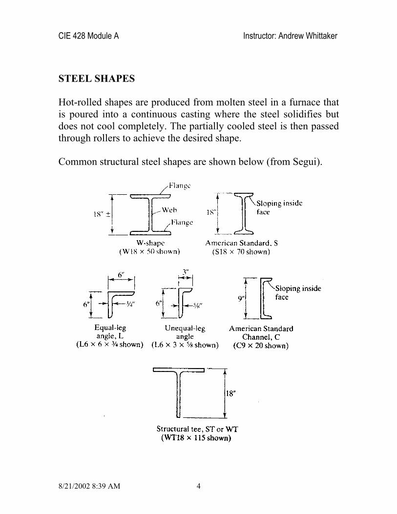
STEEL SHAPES
Hot-rolled shapes are produced from molten steel in a furnace that is poured into a continuous casting where the steel solidifies but does not cool completely. The partially cooled steel is then passed through rollers to achieve the desired shape.
Common structural steel shapes are shown below (from Segui).
CIE 428 Module A Instructor: Andrew Whittaker
8/21/2002 8:39 AM 5
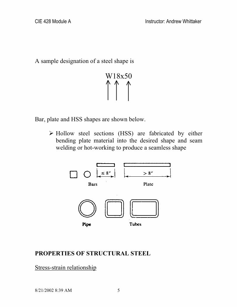
A sample designation of a steel shape is
W18x50
Bar, plate and HSS shapes are shown below.
Hollow steel sections (HSS) are fabricated by either bending plate material into the desired shape and seam welding or hot-working to produce a seamless shape
PROPERTIES OF STRUCTURAL STEEL
Stress-strain relationship
CIE 428 Module A Instructor: Andrew Whittaker
8/21/2002 8:39 AM 6
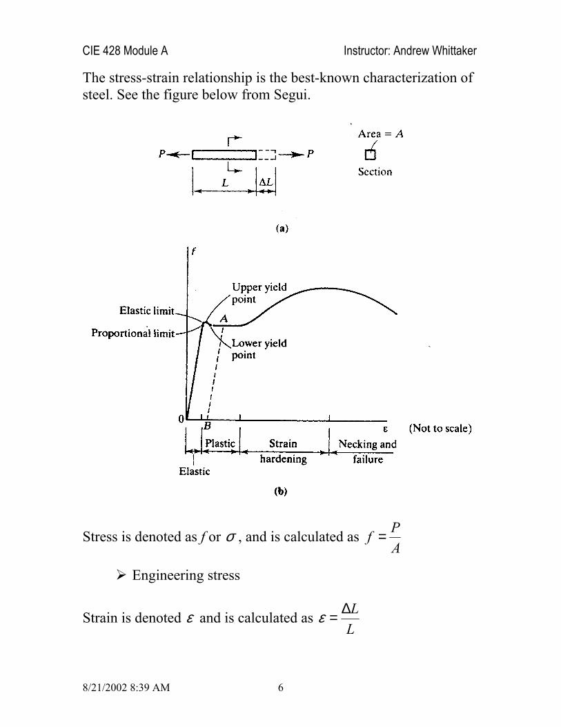
The stress-strain relationship is the best-known characterization of steel. See the figure below from Segui.
Stress is denoted as f or σ , and is calculated as PfA
=
Engineering stress
Strain is denoted ε and is calculated as LL
ε ∆=
CIE 428 Module A Instructor: Andrew Whittaker
8/21/2002 8:39 AM 7
Engineering strain
The figure above shows 4 ranges of response
Elastic
Plastic (yield plateau)
Strain hardening
Necking and failure (strain softening)
Many steels are ductile. Ductility is a measure of post-yield elongation, where elongation is calculated as
0
0
( )fL Le
L
−=
where
fL =
0L =
An idealized stress-strain relationship is shown in the figure on the following page from Segui. The important descriptors are
yF : the yield point
uF : the ultimate tensile strength

CIE 428 Module A Instructor: Andrew Whittaker
8/21/2002 8:39 AM 8
E: Modulus of elasticity or Young’s modulus (29,000 ksi)
For high-strength steels, the stress-strain relationships are often similar to that shown below (from Segui).
Note from the above figure that
Elastic range
No well-defined yield point
CIE 428 Module A Instructor: Andrew Whittaker
8/21/2002 8:39 AM 9
Ultimate tensile strength
Because steel design makes use of yield strength and a tensile strength, a definition of yield strength is needed for these steels
0.2% offset (residual strain) method used
Chemical composition
The chemical composition of a steel determines its mechanical properties of
Strength
Ductility
Hardness (resistance to plastic deformation)
Closely related to ultimate strength
Toughness
The principal components of steel, an alloy, are iron (large %) and carbon (smaller %). Carbon contributes to strength but not ductility. Other components include Manganese (Mn), Silicon (Si), Chromium (Cr), Molybdenum (Mo), Vanadium (V), Nickel (Ni), and Copper (Cu).
The concept of carbon equivalent (CE) was introduced to convert into equivalent carbon content the effect of other elements known to increase the hardness of steel. The AWS definition of CE is:
(Mn+Si) (Cr+Mo+V) (Ni+Cu)CE=C+ + +6 5 15
CIE 428 Module A Instructor: Andrew Whittaker
8/21/2002 8:39 AM 10
where C is the % carbon, etc.
If strength increases, hardness increases, ductility decreases, and weldability decreases.
If CE is high, say 0.4 to 0.5, then the potential for cracking in the HAZs of welded connections is increased.
Limits on CE not found in ASTM standards but other limits are used to control maximum % of elements, etc.
Structural steels are often grouped by broad composition, namely,
Plain carbon steels
Mostly iron and carbon, less than 1% C
Low-alloy steels
Iron, carbon and other components (<5% by volume)
Increase in strength, reduction in ductility
High-alloy or specialty steels
For example, ASTM A36 steel is a plain carbon steel with the following components other than iron:
Carbon: 0.26% maximum
Phosphorous: 0.04% maximum
Sulphur: 0.05% maximum

CIE 428 Module A Instructor: Andrew Whittaker
8/21/2002 8:39 AM 11
Consider the figure from Bruneau on the following page that shows generic stress-strain relationships for different steels.
What are the key observations from this figure?
Effect of temperature on the properties of structural steel
Elevated temperatures generally degrade the properties of structural steel. Threshold temperatures vary as a function of mechanical property under consideration. See the figure below from Bruneau et al. for sample information on the effect of

CIE 428 Module A Instructor: Andrew Whittaker
8/21/2002 8:39 AM 12
temperature on yield stress, tensile strength, and Young’s modulus.

CIE 428 Module A Instructor: Andrew Whittaker
8/21/2002 8:39 AM 13
CIE 428 Module A Instructor: Andrew Whittaker
8/21/2002 8:39 AM 14
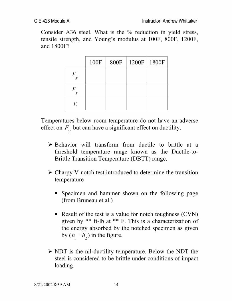
Consider A36 steel. What is the % reduction in yield stress, tensile strength, and Young’s modulus at 100F, 800F, 1200F, and 1800F?
100F 800F 1200F 1800F
yF
yF
E
Temperatures below room temperature do not have an adverse effect on yF but can have a significant effect on ductility.
Behavior will transform from ductile to brittle at a threshold temperature range known as the Ductile-to-Brittle Transition Temperature (DBTT) range.
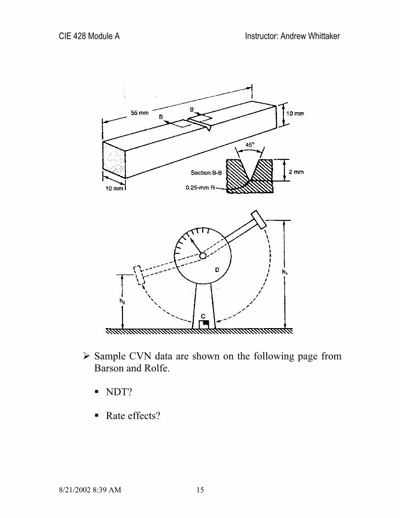
Charpy V-notch test introduced to determine the transition temperature
Specimen and hammer shown on the following page (from Bruneau et al.)
Result of the test is a value for notch toughness (CVN) given by ** ft-lb at ** F. This is a characterization of the energy absorbed by the notched specimen as given by ( 1 2h h− ) in the figure.
NDT is the nil-ductility temperature. Below the NDT the steel is considered to be brittle under conditions of impact loading.
CIE 428 Module A Instructor: Andrew Whittaker
8/21/2002 8:39 AM 15
Sample CVN data are shown on the following page from Barson and Rolfe.
NDT?
Rate effects?

CIE 428 Module A Instructor: Andrew Whittaker
8/21/2002 8:39 AM 16
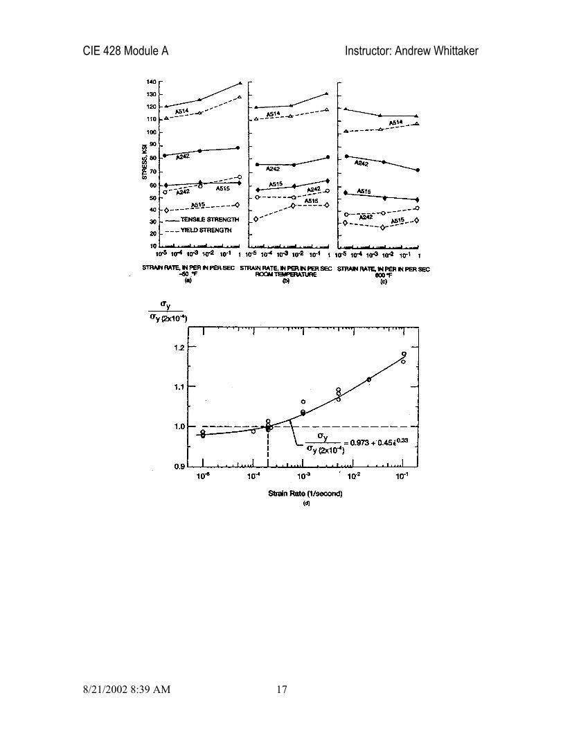
Effect of strain rate on mechanical properties of steel
Strain rate will affect the shape of the stress-strain relationship.
Yield stress and tensile strength will generally increase with strain rate.
Strain rate effects only significant for blast engineering
% increase in yield stress and tensile strength is dependent on temperature
See the figure from Bruneau et al. on the following page for sample information
CIE 428 Module A Instructor: Andrew Whittaker
8/21/2002 8:39 AM 17
CIE 428 Module A Instructor: Andrew Whittaker
8/21/2002 8:39 AM 18
CONCEPTS IN STRUCTURAL STEEL DESIGN
Steel structures can be designed using one of three approaches
Allowable stress deign (ASD)
Plastic design
Load and resistance factor design (LRFD)
Each of these is summarized in turn below. CIE 428 will focus exclusively on LRFD.
Allowable stress design
Allowable stress design (ASD) is also called working stress design.
Working stresses are calculated from the working loads using best estimates of the applied loads
Allowable stresses (under working loads) are calculated by dividing the yield stress or tensile strength by a factor of safety.
No information on how safe is the design.
Plastic design
Plastic design is based on a consideration of failure conditions rather than load conditions.
Rarely used in practice
Similar to LRFD that is described next

CIE 428 Module A Instructor: Andrew Whittaker
8/21/2002 8:39 AM 19
Load and resistance factor design (LRFD)
Load and resistance factor design is similar to plastic design in that strength (the failure condition) is considered, where
Factored load Factored strength≤
where the factored load is the sum of the load effects multiplied by the load factors and the factored strength is equal to the resistance multiplied by the resistance factor. In this approach, the factored loads bring the member to its limit.
The above relationship can be written as follows:
i i nQ Rγ φ≤∑
where
iγ = Load factor
iQ = Load effect (force or moment)
nR = Nominal resistance of component
φ = Resistance factor
nRφ = Design strength
Load factors are not constant for a given load effect (D, L, S, R, W, E, for example)
Arbitrary point-in-time values
Lifetime maximum
CIE 428 Module A Instructor: Andrew Whittaker
8/21/2002 8:39 AM 20
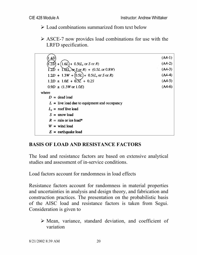
Load combinations summarized from text below
ASCE-7 now provides load combinations for use with the LRFD specification.
BASIS OF LOAD AND RESISTANCE FACTORS
The load and resistance factors are based on extensive analytical studies and assessment of in-service conditions.
Load factors account for randomness in load effects
Resistance factors account for randomness in material properties and uncertainties in analysis and design theory, and fabrication and construction practices. The presentation on the probabilistic basis of the AISC load and resistance factors is taken from Segui. Consideration is given to
Mean, variance, standard deviation, and coefficient of variation

CIE 428 Module A Instructor: Andrew Whittaker
8/21/2002 8:39 AM 21
Probability density function (pdf)
Randomness and uncertainty in loads and resistances
( ), ( ), ( )Rf Q f R f InQ
Cumulative distribution function (cdf)
Reliability index
Members
Connections
Structure?
Values calibrated to the then current practice.


![[XLS]web.iku.edu.trweb.iku.edu.tr/courses/insaat/ce636/LRFD_composite_beam... · Web viewWT155X43 WT155X39.5 WT155X37 WT155X33.5 WT155X30 WT155X26 WT155X22.25 WT155X19.35 WT155X16.35](https://img.dokumen.tips/doc/110x75/5abe21c07f8b9aa3088c8204/xlswebikuedutrwebikuedutrcoursesinsaatce636lrfdcompositebeamweb.jpg)