Embed Size (px)
Citation preview

1
Modulation with continuous wave
•representations in time and frequency for two types of continuous wave modulation:
–Amplitude modulation, AM -amplitude
–Angle modulation,•frequency modulation (FM) - instantaneous frequency•phase modulation (PM) - instantaneous phase
2
• Purpose of a communication system: – transport a signal (a message) over a channel– deliver a reliable estimate to a user
• Example: – radio system: efficient in a freq. range > 30 kHz, – baseband signals = audio signals (0-20kHz)– Frequency shifting => modulation
• The message signal that contains information, generated by sources of information, is a baseband signal
• Modulation – information transfer from the modulating wave to carrier.

3
• Modulation / demodulation– (1) shifting frequency range of message signal into
another one- suitable for transmission over the channel
– (2) corresponding shift back to the original frequency range after reception of the signal
• Two most common used forms of carriers– Sinusoidal wave– Periodic pulse wave
• two main classes of modulation– Continuous wave (CW)– Pulse modulation
4
Amplitude modulation
• The amplitude of a carrier sine wave is modified according to a message signal= information
Angle modulation• instantaneous frequency / phase of the
carrier sine wave varies with the message– Frequency modulation– Phase modulation

5
Essential components of a communication system, using
continuous-wave (CW) modulation
The noise from the channel decreases performance of the overall scheme
6
Amplitude modulation vs Angle modulation (exponential)

7
Amplitude modulation( )( )( ) ( ) ( )
-1
Sinusoidal carrier wave: cos
Modulating signal:
AM signal: 1 cos .
V - amplitude sensitivity of the modulator
c c
c a c
a
c t A t
x t
s t A k x t t
k
= ω
= + ω⎡ ⎤⎣ ⎦⎡ ⎤⎣ ⎦
Modulation degree or p
( ) [ ]max
(index):
100 % ;0 1; (message=sine wave)
= maximum frequency of the modulating signala a m
M
m k x t m m k A
f
= ⋅ < ≤ =
ercentage
8
varying percentage of modulation
1) |kax(t)|≤12) |kax(t)|>1: overmodulation; envelope distortions, phase
inversion in the carrier
( )( )
( )
The amplitude of a harmonic signal is positive: 1 0
1
If 1
c a
a
a
A k x t
k x t t
k x t
+ ≥⎡ ⎤⎣ ⎦⇒ ≤ ∀
> ⇒ overmodulation
m >1

9
Measuring modulation index
0 1 2 3 4 5 6
x 10-4
-1.5
-1
-0.5
0
0.5
1
1.5
timp
ampl
itudi
ne
Amin
Amax
max min
max min
100 [%]A AmA A
−= ⋅
+Valid when the modulating signal is a sine wave
10
AM Spectrum
( ) { } ( ){ }
( ) ( ) ( ) ( ) ( )
( ) ( ) ( ) ( ) ( )
( ) ( ) ( ) ( ) ( )
cos cos
1 ,2
.2
.2 2
The notation S(f) is used in communicati
c c c a c
c c c c a c c
a cc c c c c
c a cc c c c
S A t A k x t t
A A k X
k AS A X X
A k AS f f f f f X f f X f f
ω = ω + ω =
= π δ ω−ω + δ ω+ω + ω ∗π δ ω−ω + δ ω+ω⎡ ⎤ ⎡ ⎤⎣ ⎦ ⎣ ⎦π
ω = π δ ω−ω + δ ω+ω + ω−ω + ω+ω⎡ ⎤ ⎡ ⎤⎣ ⎦ ⎣ ⎦
= δ − + δ + + − + +⎡ ⎤ ⎡ ⎤⎣ ⎦ ⎣ ⎦
F F
ons.

11
( ) ( ) ( ) ( ) ( )2
a cc c c c c
k AS A X Xω = π δ ω−ω + δ ω+ω + ω−ω + ω+ω⎡ ⎤ ⎡ ⎤⎣ ⎦ ⎣ ⎦
Magnitude spectrum for the baseband signal and AM signal
12
Condition to recover correctly the message signal & Bandwidth
• Upper and lower sidebands do not overlap if
• Bandwidth of the modulated signal, BTis double of the bandwidth of the message (modulating) signal, B
0C Mω −ω >
2TB B=
(message's bandwidth)c Mf f B>> =

13
AM advantages and disadvantages
+simple implementation– used from the
beginning in radio transmission
– cheaper
– bandwidth is 2x bandwidth of modulating wave
– low energy efficiency– AM spectrum: the carrier
~ no information ⇒waste of power
– Solution: suppress one of the sidebands and carrier ⇒ linear AM
14
Modulator
• nonlinear device, i.e. diode

15
( ) ( ) ( ) ( ) ( )
( ) ( ) ( )
1 2
1
1
cos cos
11 2 cos 2 12 2 1
c c c c
n
cn
u t A t x t u t A t x t g t
g t n tn
−∞
=
= ω + ⇒ = ω +⎡ ⎤⎣ ⎦
−= + − ω⎡ ⎤⎣ ⎦π −∑
( ) ( ) ( ){ }( ) ( ) ( ) ( )
( )
1
21
1
1
1cos cos 2 cos 2 2
2 2 1
12 cos 2 1 2 2 1For , in the neighborhood of
2cos cos 2
AM signal - separated by band-pass
nc c
c c cn
n
cn
c M c
cc c
A Au t t n t n tn
x tx t n t
n
A t x t t
−∞
=
−∞
=
−≅ ω + ω + − ω +⎡ ⎤⎣ ⎦π −
−+ + − ω⎡ ⎤⎣ ⎦π −
ω >> ω ω
ω + ωπ
∑
∑
filtering centered on cω
16
Demodulator : envelope detector
•low-pass filtering of u2(t) -> capacitor•removal of the DC component

17http://www.discip.crdp.ac-caen.fr/phch/lycee/terminale/modem/modem.htm
http://www.discip.crdp.ac-caen.fr/phch/lycee/terminale/modem/modem.htm
18
http://www.discip.crdp.ac-caen.fr/phch/lycee/terminale/modem/modem.htm

19
http://www.discip.crdp.ac-caen.fr/phch/lycee/terminale/modem/modem.htm
20
http://www.discip.crdp.ac-caen.fr/phch/lycee/terminale/modem/modem.htm

21
Power of AM signal( )
( ) [ ] ( )
( ) ( ) ( )
( )
2
2 2 2 2 2 22
cos
cos cos
cos cos cos 2 2
Power of the modulating signal 2
Power of the AM signal : 22 8 8 4
m m
c a m m c
c cc c c m c m
mm
c c c cs
x t A t
s t A K A t tmA mAA t t t
AP
A m A m A AP m
= ω
= + ω ω
= ω + ω −ω + ω +ω⎡ ⎤ ⎡ ⎤⎣ ⎦ ⎣ ⎦
=
= + + = +
22
( )
2 2
22
2
max
For detection, use only one sideband, amplitude 2.
Useful power 8
Efficiency at receiver ;0 12 2
1Maximum efficiency 100 16.67% (m=1)6
P
c
cu
u
S
mA
m AP
P m mP m
=
η = = < ≤+
η = ⋅ ≅
2 2
2
max2
ower from both sidebands = useful , / 4,
double efficiency : , 33.33%2
uP m A
mm
=
η = η =+

23
observation
• This amplitude modulation is not linear
( ) ( ) ( ) ( )( )
( ) ( )( ) ( ) ( ){ } ( ) ( )
1 1 2 2
1 2
1 2
1 2 1 2 1 2
1 cos ; 1 cos ;
If results from the modulation with the sum
+ we have
1 cos
c a c c a c
c a c
s t A k x t t s t A k x t t
s t
x t x t
s t A k x t x t t s t s t
+
+
= + = +⎡ ⎤ ⎡ ⎤⎣ ⎦ ⎣ ⎦
= + + ≠ +⎡ ⎤⎣ ⎦
ω ω
ω
24
Linear Amplitude Modulation
( ) ( ) ( )( ) ( ) ( ) ( )( ) ( )
( )( )
cos
cos cos sin sin
cos sin ,
canonical form of a bandpass signal in phase component (I-channel),
in quadrature component (Q-chann
c
c c
I c Q c
I
Q
s t a t t t
a t t t a t t t
s t t s t t
s t
s t
= ω + φ⎡ ⎤⎣ ⎦= φ ω − φ ω⎡ ⎤ ⎡ ⎤⎣ ⎦ ⎣ ⎦= ω − ω
−
−
( ) ( ) ( )el).
linear modulation and - linear dependent on I Qs t s t x t⇔

25
Linear Amplitude Modulation
( )x t ( )x t
( )tx21 ( ) ( ){ }x̂ t x t=H
( )tx21 ( ) ( ){ }x̂ t x t=H
( )tx21 ( )t'x
21
( )tx21 ( )t'x
21
−the vestige of the inferior sideband is transmitted
the vestige of the superior sideband is transmitted
with vestigial sideband VSB
inferiorsidebandis transmitted
Superior sidebandis transmitted
Single sideband SSB
-message0Double sideband suppressedcarrier DSB-SC
ObservationsIn quadrature component
In phase component
Modulation type
( )1 ˆ2
x t
( )1 ˆ2
x t−
DSB-SC –suppressed carrier, bandwidth is the same as full AM
VSB – large bandwidth signals
26
Observations
• in phase component sI(t) depends only on the message signal
• in quadrature component sQ(t) = filtered version of the message signal. The spectral modification of s(t) compared to x(t) is given only by sQ(t)
• The purpose of sQ(t) if it exists, is to interfere with the in phase component to eliminate /reduce the power from a sideband of the modulated signal

27
Double sideband-suppressed carriermodulation
( ) ( ) ( ) ( ) ( )[ ].XXAStcostxAts ccc
cc ω+ω+ω−ω=ω⇒ω=2
28
• carrier multiplied with the message signal
• carrier absent in thespectrum
• But S(ω) has spectral components in ω=ωc !
• transmitted bandwidth= 2xbandwidth of the modulating wave

29
Coherent (Synchronous) Detection• reconstruct modulating signal x(t)
30
( ) ( ) ( ) ( ) ( )
( )
( )
( ) ( )
( )
cos cos cos
cos cos 22 2
centered in 2 , 2 , 2 base band ,
c c c c
c cc
C M C MM M
v t s t t A x t t tA Ax t x t t
c
= ω + θ = ω ω + θ
= θ + ω + θ
ω ω −ω ω +ω−ω ω
( ) ( )0 cos (LPF output)2
Desynchronisation between local oscillators - receiver & emission unit phase error decreasing of detector response.
maximum for 0; zero for . 2
Local osci
cAv t x t= θ
⇒ θ⇒π
θ = θ = ±
llator of the receiver with the local oscillatorthat generates the carrier signal and
synchronizedin frequency in phase

31
Quadrature-Carrier multiplexing
• Also known as Quadrature-amplitude modulation (QAM)
• Transmit two DSB-SC modulated waves on the same banwidth ⇒ bandwidth-conservation scheme
• Modulators with quadrature phase:– carriers in quadrature, same frequency, differ in phase
by ±π/2 (±900)• Demodulator: two coherent detectors with 90
degree phase shift• θ=±π/2: output of synchronous detector = null
(quadrature effect)
32
( ) ( )( ) ( ) ( )1 2
1 2
, - independently modulating signals.
cos sinc c c c
x t x t
s t A x t t A x t tω ω= +

33
Single side band modulation – SSB• one sideband transmitted• frequency-discrimination scheme with 2 steps• Product modulator ⇒ double sideband-suppressed
carrier• Bandpass filter : passes the sideband selected for
transmission and suppresses the remaining sidebands• separation lower and upper sideband ⇒ energy gap
in the spectrum of the message signal x(t)• Speech signals (telephony): energy gap= -300, 300
Hz• modulated signal: energy gap 2ωm
34
Restrictions for BPF of sideband selection:1. selected sideband passing band of the filter, 2. unwanted sideband stop band of the filter,filter's transition bandwidth 2 . Demodulation- synchron
m
⊂⊂
< ωous detection.
35
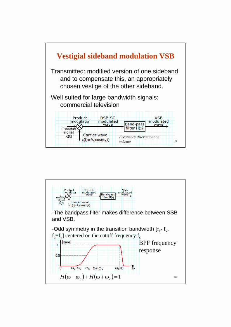
Vestigial sideband modulation VSB
Transmitted: modified version of one sideband and to compensate this, an appropriately chosen vestige of the other sideband.
Well suited for large bandwidth signals: commercial television
Frequency discrimination scheme
36( ) ( ) 1=ω+ω+ω−ω cc HH
BPF frequencyresponse
-The bandpass filter makes difference between SSB and VSB.
-Odd symmetry in the transition bandwidth [fc- fv, fc+fv] centered on the cutoff frequency fc

37
• The sum of its magnitude at frequencies symmetrically with fc is 1, in the transition bandwidth
• Phase is linear• The transmission bandwidth is
( ) ( ) 1=ω+ω+ω−ω cc HH
2T vB B f= + π
-message bandwidth; = -vestigial bandwidth2
vvB f ω
π
38
• “+” is for transmitting a vestige from the upper sideband
• “-” is for the lower sideband vestige
( ) ( ) ( )1 1cos sin2 2c c c cs t A x t t A x t t′= ±ω ω
( ) ( )( ) ( )
in quadrature component of the signal
obtained by filtering with Q
x t s t
x t H
′ −
ω
( ) ( ) ( ) ; Q c cH j H H B Bω = ω−ω + ω+ ω − ≤ ω≤⎡ ⎤⎣ ⎦

39
40
• SSB modulation can be seen as VSB with vestige reduced to zero
• The filter for the in quadrature component:
• Or ( ) sgnQH jω = − ω
( ) ( ){ }x t x t′ =H

41
• The video signal bandwidth is large with significant low frequencies spectral components. Hence the VSB
• Demodulation circuits must be simple (affordable). This requirement imposes envelope detection hence transmitting the carrier besides the VSB signal
• In reality, since at transmitter the power is high, the VSB filter is used at receiver (low power, relatively affordable filter)
42
Video signal spectrum
VSB filter characteristic at receiver

43
• North America: channel bandwidth 6 MHz • Picture carrier: 55,25 MHz• Sound carrier: 59,75 MHz• Image signal spectrum is 1,25MHz below carrier, and
4,5MHz above it
44
• Adding the carrier:
• m-modulation degree. • At envelope detection:
( ) ( ) ( )1 11 cos sin2 2c c c cs t A mx t t mA x t t⎡ ⎤ ′= + ±⎢ ⎥⎣ ⎦
ω ω
( ) ( )( )
( )
211 21 1 12 1
2
c
mx ta t A mx t
x t
⎡ ⎤′⎢ ⎥⎡ ⎤= + + ⎢ ⎥⎢ ⎥⎣ ⎦ +⎢ ⎥⎣ ⎦

45
• The signal is distorted at the receiver. This can be reduced by
-reducing the modulation degree-increasing vestigial bandwidth to reduce
x’(t)The vestigial bandwidth 0,75MHz (1/6 of the
bandwidth) is chosen such that distortion is acceptable even for m=100%
46
Frequency translation
2 1
2 1
2 1
1 2
Up conversion
Down conversion l
l
ω > ωω = ω −ω
ω < ωω = ω −ω
• Change the carrier frequency of the modulated signal from ω1 to ω2
• Mixer: product modulator+bandpass filter

47
Up conversion, ω2>ω1
Spectrum of the modulated signal with up conversion
Image signal spectrum
48
Down conversion, ω2<ω1
Image signal spectrum
Spectrum of the modulated signal with down conversion

49
Frequency Division Multiplexing
• Telephony systems: 300Hz-3400Hz• Goal: transmit simultaneously several
vocal signals on the same channel:– FDM-frequency division multiplexing– TDM-time division multiplexing
• FDM, using AM-SSB• Distance between carriers 4kHz• BPFs – bandwidth limitation at 4kHz
50
Frequency Division Multiplexing
LPF -remove high frequency components
AM Modulators modulate the signals on different carrier frequencies

51
52
Angular Modulation
• modulate a carrier : alter its angle –phase, according to the message; amplitude ~constant
• Advantage: signal more robust against noise and interference.
• Disadvantage: increase in bandwidth

53
Angular Modulation
( )( ) ( )
( )
Modulated signal- rotating vector with amplitude and angle :
cos Its angular velocity:
.
c
i
c i
i
At
s t A t
dt
θ
= θ
ω =
instantaneous frequency of the modulated signal
( )i tdtθ
54
Angular Modulation
( ) ( )[ ]( ) ( )
rad/V - phase sensitivity.
cos
i c p
p
c c p
t t k x t
k
s t A t k x t
θ = ω +
⎡ ⎤= ω +⎣ ⎦
Phase modulation (PM)( ) ( )
[ ]
( ) ( )
( ) ( )
0
0
2
Hz/V - frequency sensitivity.
2
cos 2
i c f
f
t
i c f
t
c c f
t k x t
k
θ t ω t k x τ dτ
s t A t k x d
ω = ω + π
= + π
⎡ ⎤⇒ = ω + π τ τ⎢ ⎥
⎣ ⎦
∫
∫
Frequency modulation (FM).
( ) ( )0
FM signal generated using =PM signal generated using .t
x t x dτ τ∫

55
Frequency Modulation( )( )
modulating signal: cos
instantaneous frequency 2 cos
2
is the maximum instantaneous difference between FM modulated car
m m
i c f m m
f m
x t A t
t k A t
k A
= ω
ω = ω + π ω
Δω = πThe frequency deviation
( ) ( ) [ ]
rier frequency and nominal carrier frequency;
2 .
cos cos sin frequency de
f m
m m
c i c c m
k A
s t A θ t A t t
πΔωβ = =
ω ω
= = ω +β ω
The modulation index
Essential characteristic for FM : viation is proportional withmodulating signal amplitude ; does not depend on its frequency. 1 radian - . 1 radian - .
m
fA
Δ
β <<β >>
narrow band modulationwide band modulation
56
Narrow Band Frequency Modulation( ) ( ) ( )
( ) ( )
( )
cos cos sin sin sin sin .
If rad cos sin 1 and sin sin sin 36
cos sin sin .
c c m c c m
m m m
c c c c m
s t A t t A t t
t t t
s t A t A t t
ω β ω ω β ωπβ β ω β ω β ω
ω β ω ω
= −
< ⇒ ≅ ≅
⇒ = −

57
Phasorial representation of the FM and AM signals
• Narrow band FM and AM – same bandwidth
( )
( ) ( )
cos1 cos cos2
FM c c
c c m c m
s t A t
A t t
≅ ω
+ β ω +ω − ω −ω⎡ ⎤⎣ ⎦
( ) [ ]
( ) ( )
1 cos coscos
1 cos cos2
AM c m c
c c
c c m c m
s t A m t tA t
mA t t
= + ω ω
= ω +
ω +ω + ω −ω⎡ ⎤⎣ ⎦
FM AM
58
Narrow Band FM Spectrum – general case
( ) ( )( )
( ) ( )
( )( ) ( )( )
( ) ( )
0
0
cos 2
cos cos 2 sin sin 2 .
Narrow band modulation, 236
cos 2 sin .
t
y t x dt
c c f y t A
c c f c c f
f
c c c f c
s t A t k x d
A t k y t A t k y t
k A
s t A t A k y t t
= τ τ
≤
∫⎛ ⎞= ω + π τ τ =⎜ ⎟
⎝ ⎠
= ω π − ω π
ππ ≤ ⇒
≅ ω − π ω
∫
Ex: π/10=0.314, sin(π /10)=0.309
( ) ( ) ( ) ( ) ( )c cc c c c
c c
X XS A A
ω−ω ω+ω⎡ ⎤ω = π δ ω−ω + δ ω+ω + π −⎡ ⎤ ⎢ ⎥⎣ ⎦ ω−ω ω+ω⎣ ⎦

59
( ) ( ) ( ) ( )
( ) ( ) ( ) ( ) ( ) ( )
( ) ( ) ( ) ( ) ( )
( ) ( ) ( ) ( ) ( )
0
1
,
2
t
c c c c f c c
c cc c c c
c c
a cMA c c c c c
y t x d Y Xj
XS A A k
j jX X
S A A
k AS A X X
= τ τ ↔ ω = ω ⇒∫ω
ω πω = π δ ω−ω + δ ω+ω − ∗ δ ω−ω −δ ω+ω⎡ ⎤ ⎡ ⎤⎣ ⎦ ⎣ ⎦ω
ω−ω ω+ω⎡ ⎤ω = π δ ω−ω + δ ω+ω + π −⎡ ⎤ ⎢ ⎥⎣ ⎦ ω−ω ω+ω⎣ ⎦
ω = π δ ω−ω + δ ω+ω + ω−ω + ω+ω⎡ ⎤ ⎡ ⎤⎣ ⎦ ⎣ ⎦
60
Wide Band Frequency Modulation( ) [ ]
( ) ( )
( ) ( ){ }( )
( ){ }
( ) ( ) ( )
( )
sin
sin
cos sin
cos cos sin sin sin sin
Re Re ,
- complex envelope of the FM signal
-Bessel function of firs
j tmc
c m c
m
c c m
c c m c c m
s t A ej t t j t
c
jn tc n
n
n
s t A t t
A t t A t t
s t A e s t e
s t A J e s t
J x
β ω=ω +β ω ω
∞ω
=−∞
= ω +β ω
= ω β ω − ω β ω
⇒ = =
= β∑
( ) ( ) ( ) ( ) ( )
( ) ( ) ( ) ( )
t kind, order and variable .
cos cos 2
.2
c n c m c n c mn n
cn c m c m
n
n x
s t A J t n t A J f nf t
AS J n n
∞ ∞
=−∞ =−∞
∞
=−∞
= β ω + ω = β π +
ω = β δ ω−ω − ω + δ ω+ω + ω⎡ ⎤⎣ ⎦
∑ ∑
∑

61
( ) ( ) ( )
( ) ( ) ( )
( )
0 1
2
properties of Bessel's functions
1. 1 for any ,2. For small , we have:
1 ; ; 0 ; 2 ; 1 ;2
3. 1.
nn n
n
nn
J J n Z
J J J n
J
−
∞
=−∞
= − ∈
≅ ≅ ≅ > <<
=∑
β ββ
ββ β β β
β
First five Besselfunctions, J0(β)-J4(β)
62
( ) ( ) ( ) ( ) . 2
Remarks 1. FM Spectrum: component on the carrier, and an infinite setof components on the sidebands at a distance of , 2 , ... 2. 1 (narrow bandw
cn c m c m
n
c
m m c
AS J n n∞
=−∞
= − − + + +⎡ ⎤⎣ ⎦
±
<<
∑ω β δ ω ω ω δ ω ω ω
ωω ω ω
β ( ) ( )
( )
0 1
c
0
idth FM), only and have significative values carrier ( ) and two lateral bands .3. The amplitude of the component on depends on the factor
not constant. The :
c m
c
J J
J⇒ ±
⇒power is constant
β βω ω ω
ω β
( )2 2 21 1 2 2c n c
nP A J A
∞
=−∞
= =∑ β

63
Example 1
const; variable variable
variableSpectral components separated by (const).
m
m f m
m
fA f k A
f
=
⇒ Δ = ⋅
⇒ β
2 f m
m m
k Aπωβω ωΔ
= =
The amplitude of the modulating signal affects the FM spectrum
64
Example 2
[ ]
const const
variable variable+ number of sprectral components in the interval , increasesFM bandwidth 2
m f m
m
c c
A f k A
f
f f f f
f→∞
= ⇒ Δ = ⋅
⇒ =
−Δ + Δ
⎯⎯⎯→ Δβ
β
2 f m
m m
k Aπωβω ωΔ
= =
The frequency of the modulating signal affects the FM spectrum

65
The transmission bandwidth of FM signals( ) ( ) ( ) ( ) .
2For , the transmission bandwidth 2 ; centered on .
: nearly all (~98%) of the power of a FM signal lies within a bandwidth of:
cn c m c m
n
T c
T
AS J n n
B f f
B
∞
=−∞
ω = β δ ω−ω − ω + δ ω+ω + ω⎡ ⎤⎣ ⎦
β→∞ → Δ
∑
Carson's rule
1 2 2 2 1T mB f f f ⎛ ⎞≅ Δ + = Δ +⎜ ⎟β⎝ ⎠
: of transmission band.The : of transmission bandThe transmission bandwidth is found between the two estimates
−−
Carson's rule under estimationuniversal curve over estimation
66
Equivalent definition of thetransmission bandwidth
The frequency interval where the spectral components of the FM signal . have a value superior to 1% of the carrier amplitude
( )
max
max
max
2 , where for each is satisfied the condition
0,01.
The value depends on .
T m
n
B n fn n
J
n
=≤
>β
β

67
Non harmonic modulating wave
( )( )max max
- modulating signal, maximum frequency (same as )
max , frequency deviation
/ (same as ).Carson's rule: replace with and with and the unive
m
f
m
x t W f
A x t f k A
D f WD f W
= ⇒ Δ =
⇒ = Δ deviation ratio ββ
rsal curve for any modulating signal
68
Example 3
( )
North America, radio transmissions:7575 kHz ; 15 kHz ; 5.15
Carson's rule : 2 180 kHz.Universal curve : D 5 3, 2 240 kHz.In practice a transmission bandwidth of 200 kHzis used.
T
T
f W D
B f WB f
Δ = = = =
= Δ + =
= ⇒ = Δ =

69
Frequency Modulated Signals’Generation
There are 2 methods, direct - based on a voltage controlled oscillator - 555 timer indirect - 1. narrow band FM 2. frequency multiplication to set the frequency deviation. The second method high frequency stability
FM radio broadcasting⇒
⇒
70
FM Signal Generation, indirect method
narrow band FM signal ⇒ wide band FM signal by frequency multiplication
The frequency deviation is small to reduce distortions ⇒ narrow band modulation

71
( ) ( ) ( ) ( )
( ) ( ) ( ) ( )
( )
( )
0
21 2
Input: cos 2 , with
Output: ...The pass-band of the band-pass filter is times larger than of the bandwidth of the signal .
' 'cos 2
t
c c f i c f
nn
c c f
s t A t k x d f t f k x t
v t a s t a s t a s tn
s t
s t A n t nk
⎡ ⎤= + = +⎢ ⎥
⎣ ⎦= + + +
= +
∫ω π τ τ
ω π ( )
( ) ( )0
with the instantaneous
frequency: ' .
t
i c f
x d
f t nf nk x t
⎡ ⎤⎢ ⎥⎣ ⎦
= +
∫ τ τ
72
• The frequency multiplier is a nonlineardevice followed by a bandpass filter
• The nonlinear device is memoryless in the sense that it doesn’t have in itsstructure reactive elements

73
Demodulation
• Reconstruction of modulating wave• Inverse characteristic of transfer of the
characteristic of transfer of the FM modulator• 1. directly: frequency discriminator: output
proportional with the instantaneousfrequency of the FM signal.
• 2. indirectly: PLL circuit (Phase-locked loop)
74
FM quadrature demodulator
The block diagram of the demodulator
75
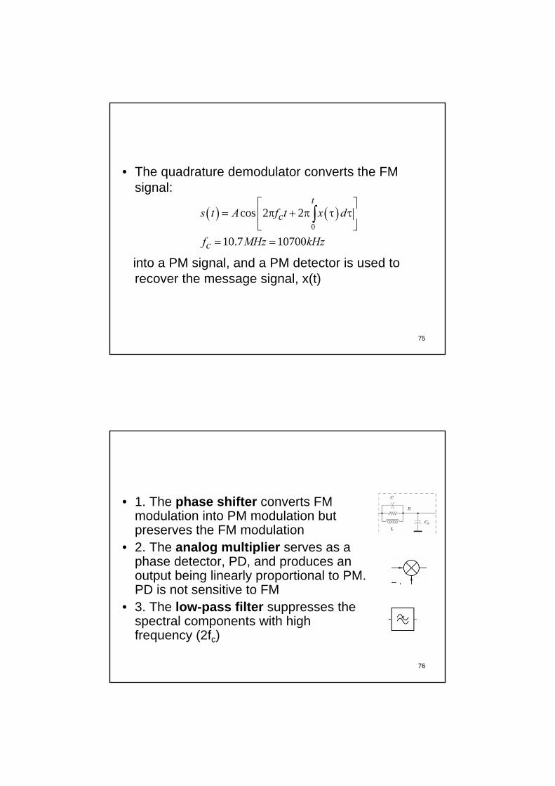
• The quadrature demodulator converts the FM signal:
into a PM signal, and a PM detector is used to recover the message signal, x(t)
( ) ( )0
cos 2 2
10.7 10700
t
c
c
s t A f t x d
f MHz kHz
⎡ ⎤= π + π τ τ⎢ ⎥
⎣ ⎦= =
∫
76
• 1. The phase shifter converts FM modulation into PM modulation but preserves the FM modulation
• 2. The analog multiplier serves as a phase detector, PD, and produces an output being linearly proportional to PM. PD is not sensitive to FM
• 3. The low-pass filter suppresses thespectral components with highfrequency (2fc)

77
The phase shift is linearly proportional to the instantaneous frequency deviation around the carrier frequency, 10700kHz.
( ) ( )
( ) ( )3
34.4290 10700150
10700 [rad], f [kHz]2
4 10
o of f
f f−
= − −
= − −
+
+ ⋅
φ
πφ
78
The phase shifted signal is :
( )
( )
0
0
3
3
( ) cos 2 10700 2 ( ) 107002
sin 2 10,700 2 ( ) 10700
4 10
4 10
t
t
s t A t k x d f
A t k x d f
ππ π τ τ
π π τ τ
−
−
⎡ ⎤= + − −⎢ ⎥
⎣ ⎦⎡ ⎤
= + −⎢ ⎥⎣ ⎦
+ ⋅
+ ⋅
∫
∫

79
But the amplitude response of the phase shifter is
80
FM
/20 log 20log 0.771 [dB]/
M M
m m
A A AA A A
= =
-2
1.093 .
The mean gain can be taken as:
20log 26.57 [dB] 4.7 10
M
m
A A cstA
A A AA
≅ ⇒ ≅
≅ − ⇒ ≅ ⋅
Maximum gain
Minimum gain
The amplitude varies only a little, and therefore we canconsider the output amplitude of the output from the phaseshifter is constant:

81
The phase detector is implemented by an analog multiplier:
( ) ( ) ( )
( )
( ) ( )
0
0
0
3
-2 2 3
-2 2 3
( ) ( )
cos 2 10700 2 sin 2 10700 2 10700
2.35 10 10700
2.35 10 sin 2 21.400 4 10700
4 10
sin 4 10
4 10
t
t
ts t s t
AA t x d t k x d f
A f
A t k x d f
π π τ τ π π τ τ
π π τ τ
−
−
−
=
⎡ ⎤ ⎡ ⎤= + + −⎢ ⎥ ⎢ ⎥
⎣ ⎦⎣ ⎦⎡ ⎤= ⋅ −⎣ ⎦⎡ ⎤
+ ⋅ + −⎢ ⎥⎣ ⎦
+ ⋅
⋅
+ ⋅
∫ ∫
∫
The low-pass filter suppresses the second component, centered at 21.4 MHz. The first component, a base-band component is retained:
( )-2 2 3ˆ( ) 2.35 10 10,700sin 4 10x t A f−⎡ ⎤= ⋅ −⎣ ⎦⋅
82
3 3( 10,700) 75 0.3 [rad]4 10 4 10f− −− ≤ ⋅ =⋅ ⋅
0.3 sinfor α α α≤ ≅
( )( )
-2 2 3
6 2
ˆ( ) 2.35 10 10700
94.12 10 10700
4 10x t A f
A f
−
−
= ⋅ −
= ⋅ −
⋅

83
• The instantaneous frequency is
• And therefore
• We have obtained a FM demodulator. The circuit configuration presented is almost exclusively used to implement a modern FM demodulator (discriminator).
10700 ( ) [kHz]f kx t= +
-6 2x̂(t) 94.2 10 ( )A kx t≅ ⋅
84
• The transfer function obtained is called an S curve
Linear portion of thecharacteristic
85
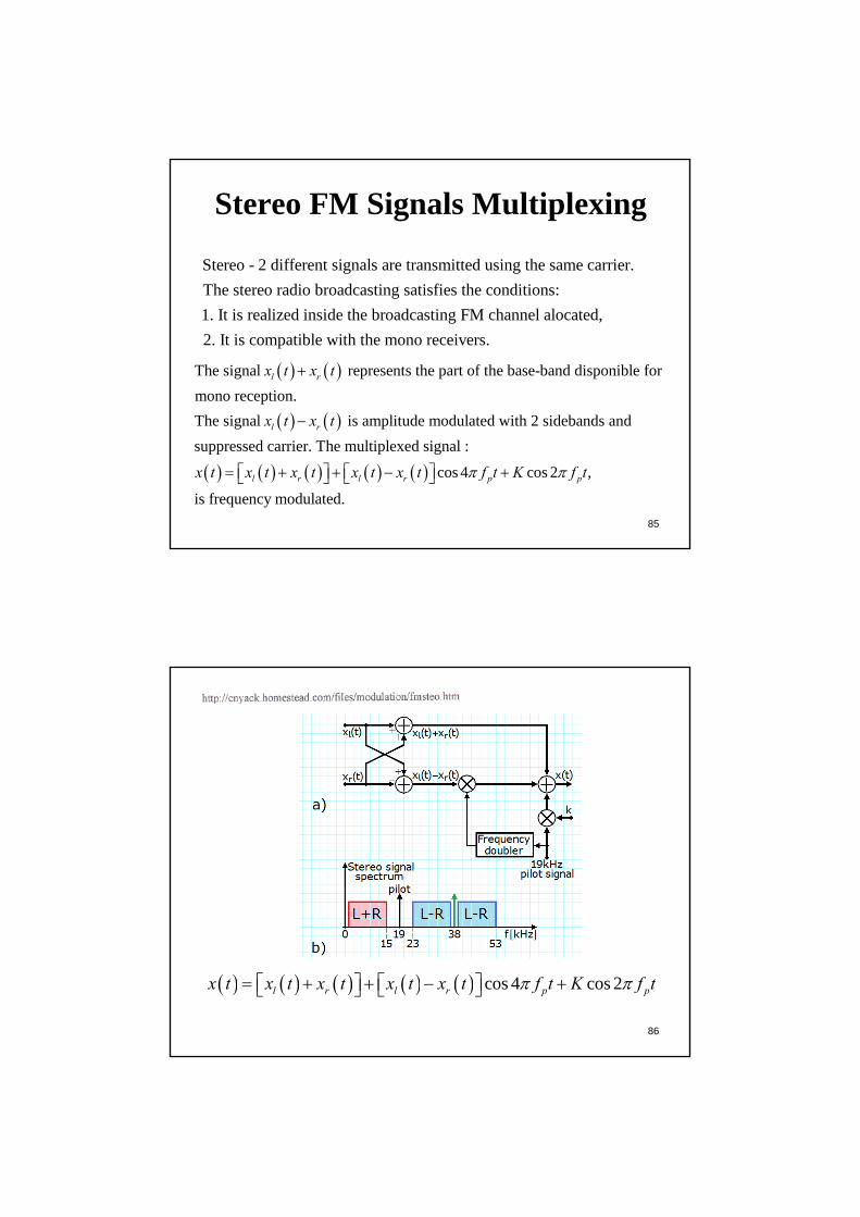
Stereo FM Signals Multiplexing
Stereo - 2 different signals are transmitted using the same carrier. The stereo radio broadcasting satisfies the conditions:1. It is realized inside the broadcasting FM channel alocated,2. It is compatible with the mono receivers.
( ) ( )
( ) ( )
( ) ( )
The signal represents the part of the base-band disponible for mono reception.The signal is amplitude modulated with 2 sidebands and suppressed carrier. The multiplexed signal :
l r
l r
l
x t x t
x t x t
x t x t
+
−
= ( ) ( ) ( ) cos 4 cos 2 ,
is frequency modulated.r l r p px t x t x t f t K f tπ π+ + − +⎡ ⎤ ⎡ ⎤⎣ ⎦ ⎣ ⎦
86
( ) ( ) ( ) ( ) ( ) cos 4 cos 2l r l r p px t x t x t x t x t f t K f tπ π= + + − +⎡ ⎤ ⎡ ⎤⎣ ⎦ ⎣ ⎦

87
88
Non-linear Effects in Frequency Modulation
• Nonlinearities in electronic circuits– Strong non-linearity which is intentional, for
given applications• Weak non-linearity• Effect of weak non-linearity on FM
systems

89
Non-linear Effects in Frequency Modulation
( ) ( ) ( ) ( )2 30 1 2 3
Consider a non-linear communication channel with the input-output transfer characteristic: , having at its input the frequency modulated si
i i iv t a v t a v t a v t= + +
( ) ( ) ( ) ( )
( ) ( ) ( )( )
0
2 20 1 2
3 33
gnal:
cos 2 ; 2
cos 2 cos 2
cos 2 .
t
i c c f
c c c c
c c
v t A f t t t k x d
v t a A f t t a A f t t
a A f t t
π φ φ π τ τ
π φ π φ
π φ
= + =⎡ ⎤⎣ ⎦
⇒ = + + + +⎡ ⎤ ⎡ ⎤⎣ ⎦ ⎣ ⎦+ +⎡ ⎤⎣ ⎦
∫
90
( ) [ ] ( )
( )
2 3
2 232 2
0 1 3
33
From the trigonometric relations: 1 cos 2 cos3 3cos cos ; cos
2 4we have:
3 cos 2 cos 4 22 4 2
cos 6 3 . 4
For the det
c cc c c c c
cc c
x x xx x
a A a Av t a A a A f t f t t
a A f t t
π π φ
π φ
+ += =
⎛ ⎞= + + + + +⎡ ⎤⎜ ⎟ ⎣ ⎦⎝ ⎠
+ +⎡ ⎤⎣ ⎦
( )0ection of the FM signal from it is necessary its identificationv t

91
( ) ( )
Let be the frequency deviation of the FM signal and the maximum frequency of the modulator signal. Ap-
plying Carson's rule we have the separation condition: 2 2 3 2 .
If thisc c c
fW
f f W f f W f f W
Δ
− Δ + > + Δ + ⇒ > Δ +
( )
( ) ( )
0
30 1 3
condition is satisfied then we can extract from ,using a band-pass filter with central frequency and band-width 2 2 , the term
3 ' cos 2 .4
c
c c c
v tf
f W
v t a A a A f t tπ φ
Δ +
⎛ ⎞= + +⎡ ⎤⎜ ⎟ ⎣ ⎦⎝ ⎠
92
The Super-heterodyne ReceiverA radio broadcasting receiver has not only the goal to demodulate the received signal.Other goals:- Selection of the desired carrier frequency,- Filtering, for the separation of the desired signal from other modulated signals,- Amplification, for the compensation of the losses produced by the propagation.

93
fLO=630+455 kHz=1085 kHz
fRF=630 kHz
Radio Timisoara
fIF=455kHz0.3-4.5 kHz
RF- radio frequency;
IF-intermediate frequency
94
; . An IF signal is generated in the receiver if the differenceof the local oscillator frequency and of the input carrier frequency equals :
IF LO RF LO RF
IF
f f f f f
f
= − >
± .
only one of these frequencies corresponds to the carrier, the other one is named 2
RF LO IF
RF IF
f f f
f f
= ±
= +image frequency
RF- radio frequency; IF-intermediate frequency

95
• For FM case, after the IF amplifier there is limiter and a bandpass filter
• Detection is made using a frequency discriminator